Drilling the Tank Angle Attach Brackets

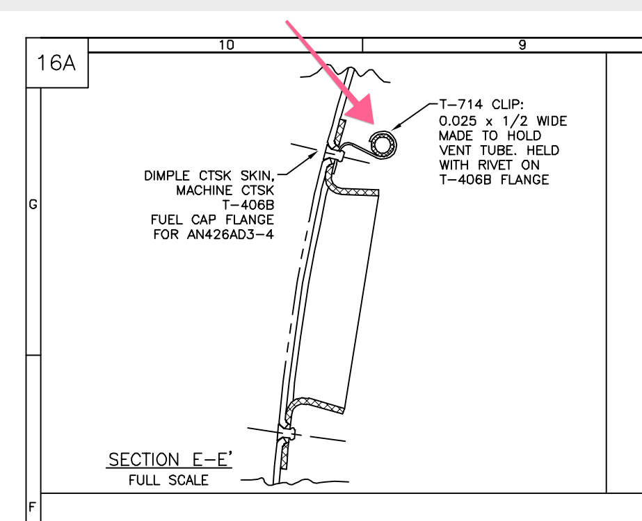
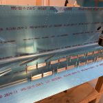
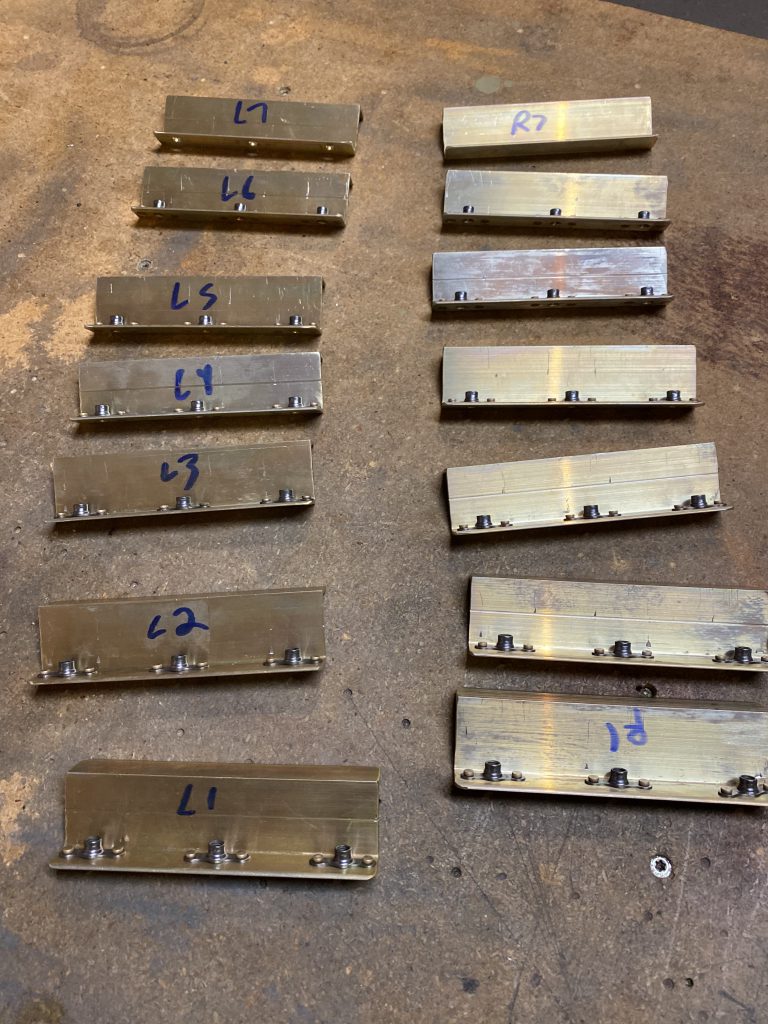
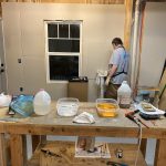
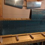
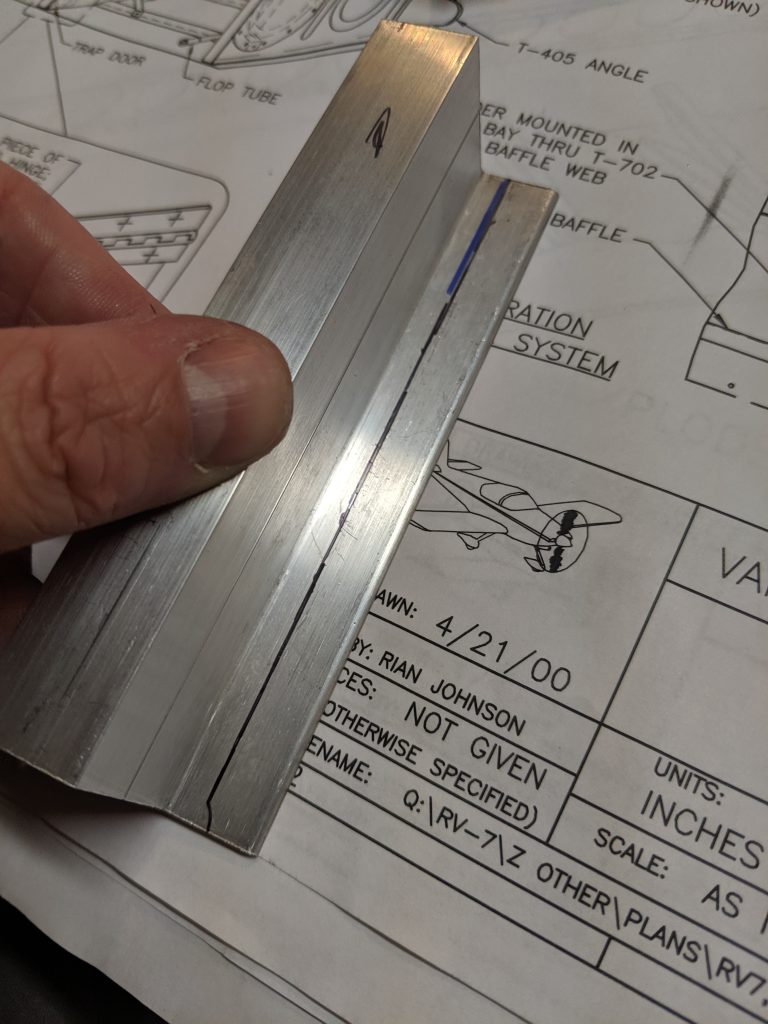
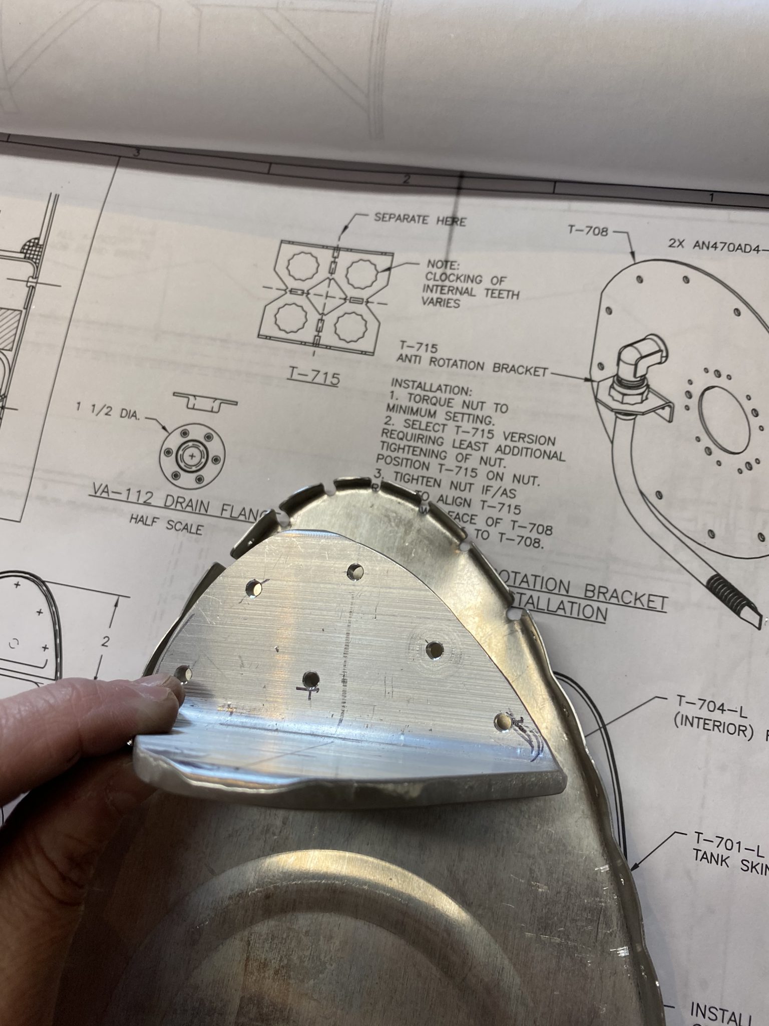
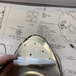
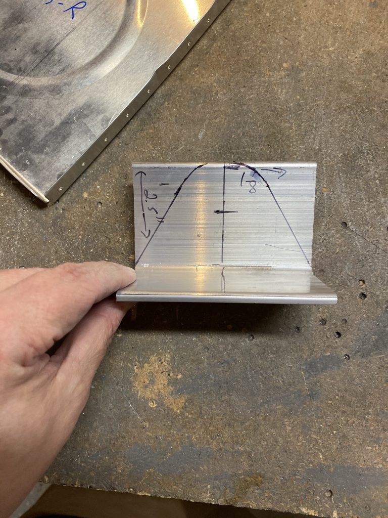
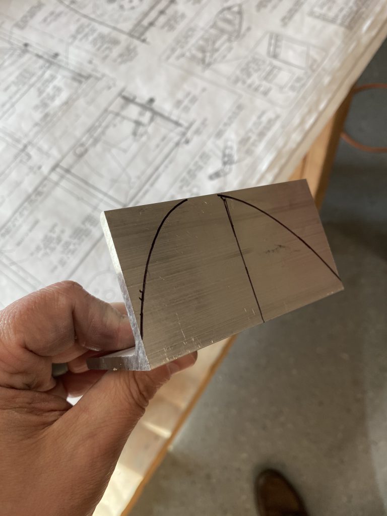
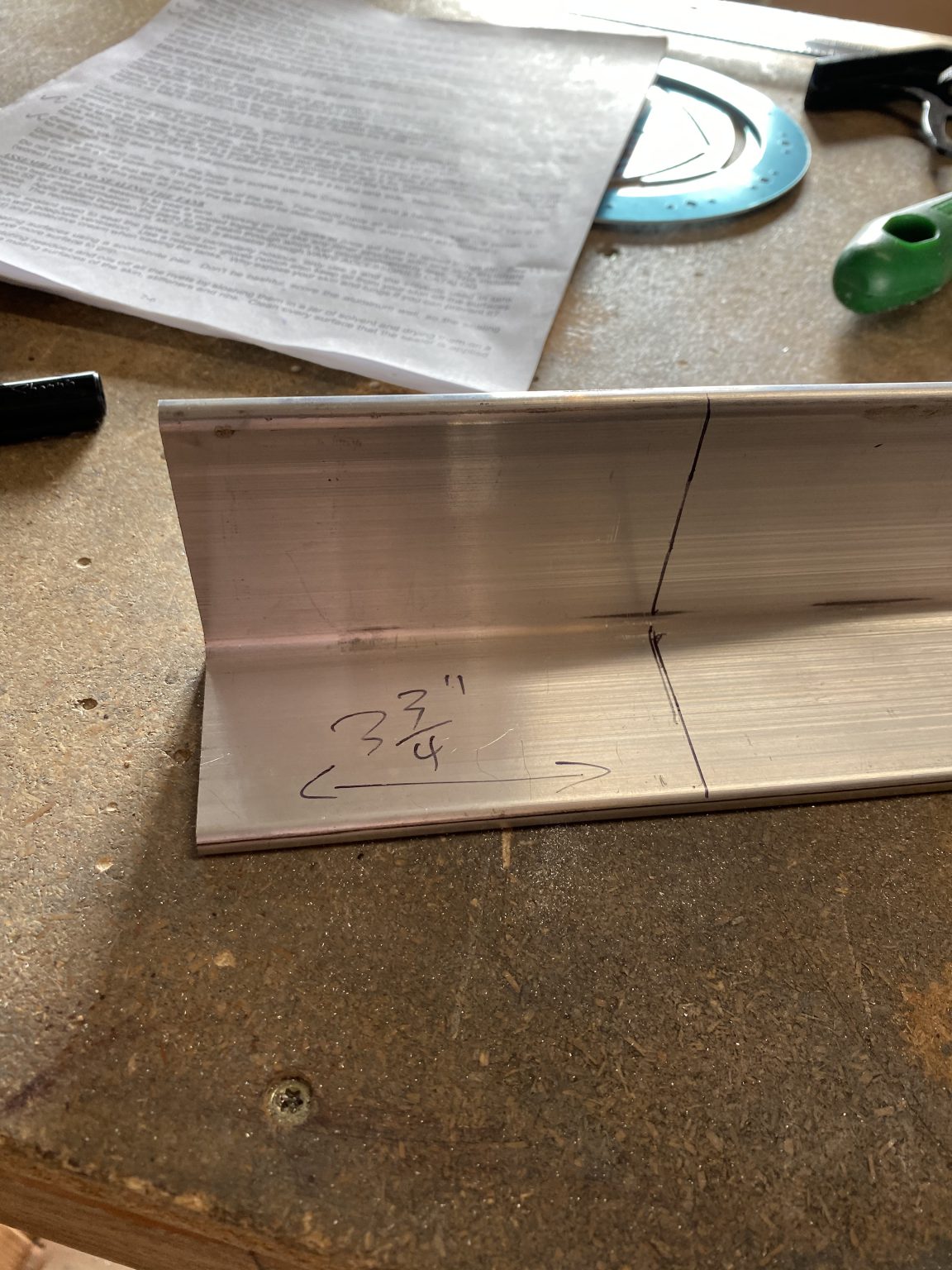
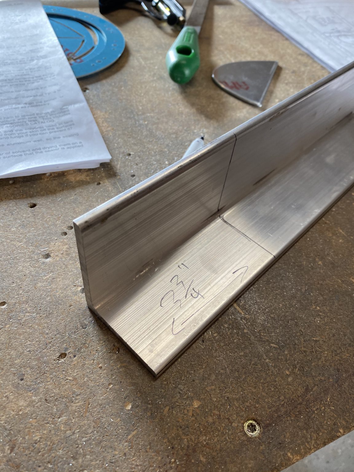
Short session to start today.  I wanted to get the tank attach angles drilled, and after doing some reading last night, this actually seems straightforward.  Vans gives us a rough idea of where to drill the rivets for the angle attach bracket in the plans with this drawing:

Image 2020-02-16 at 3.50.29 PM.png


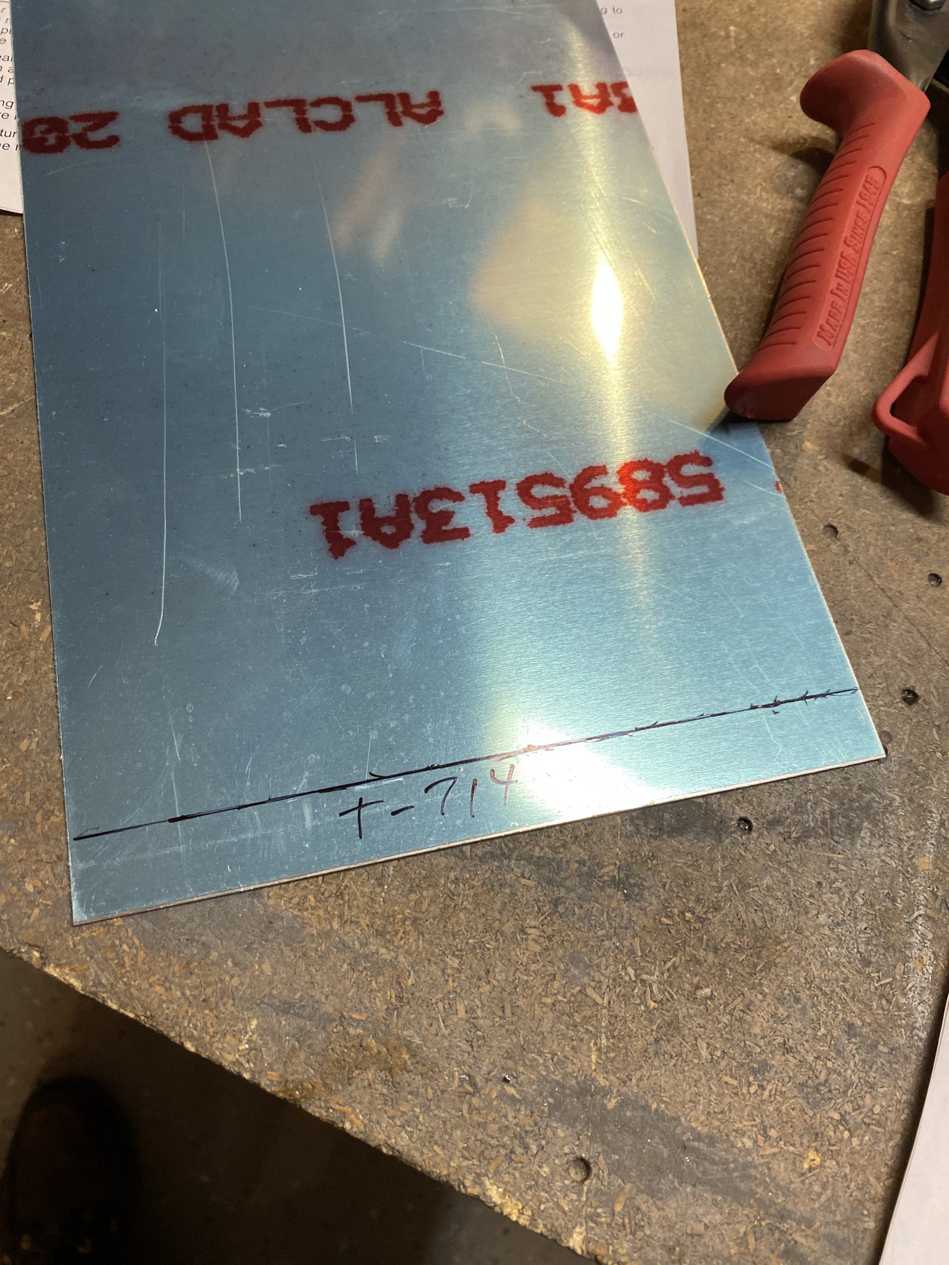
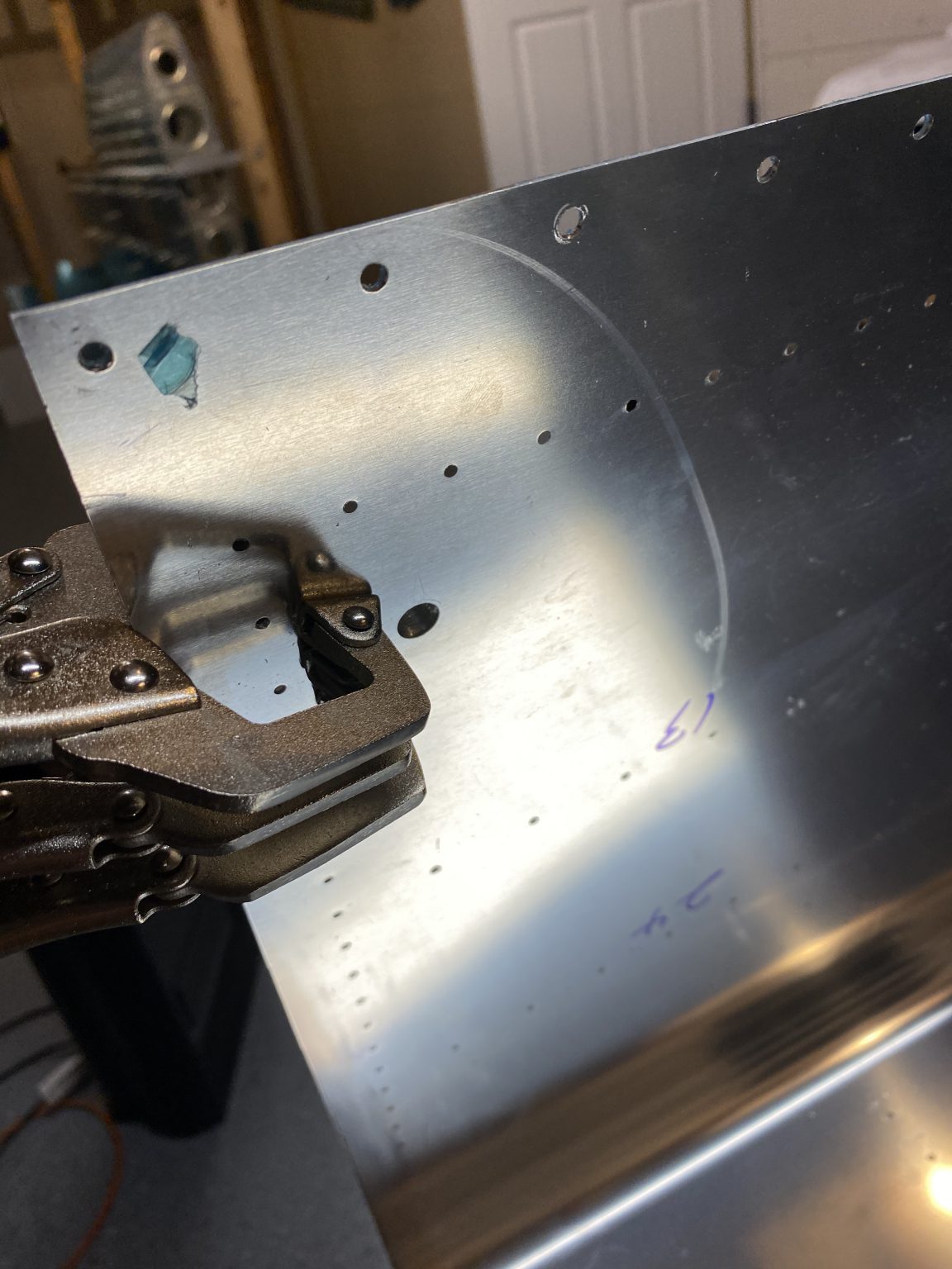
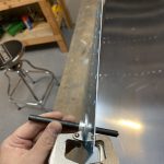
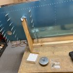
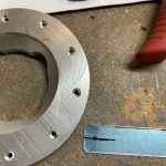
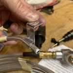
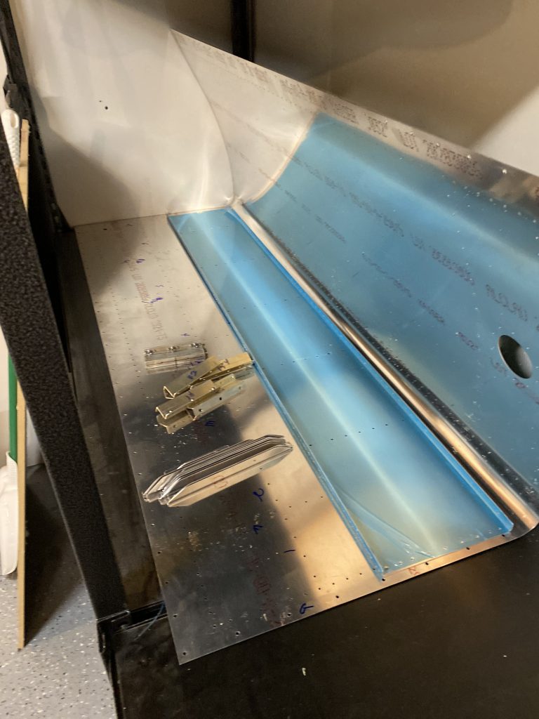
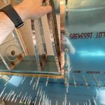
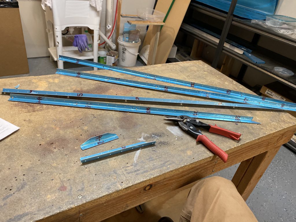
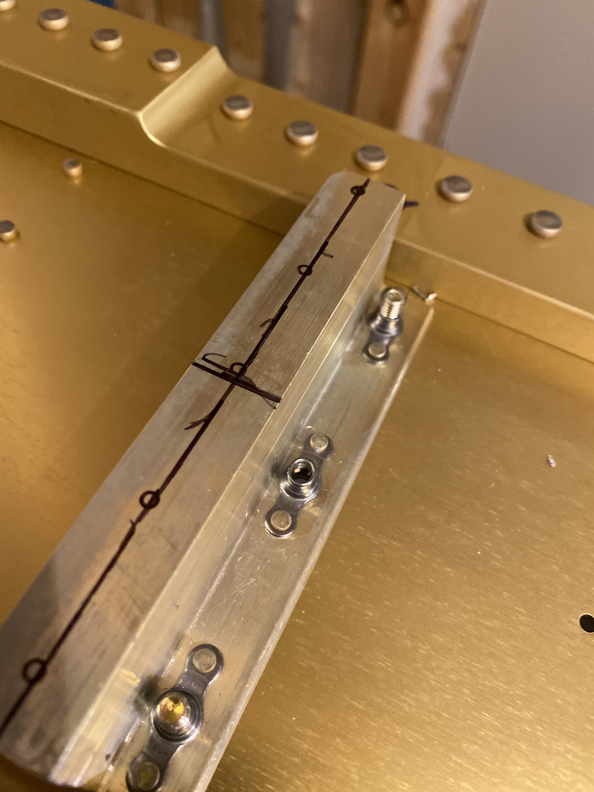
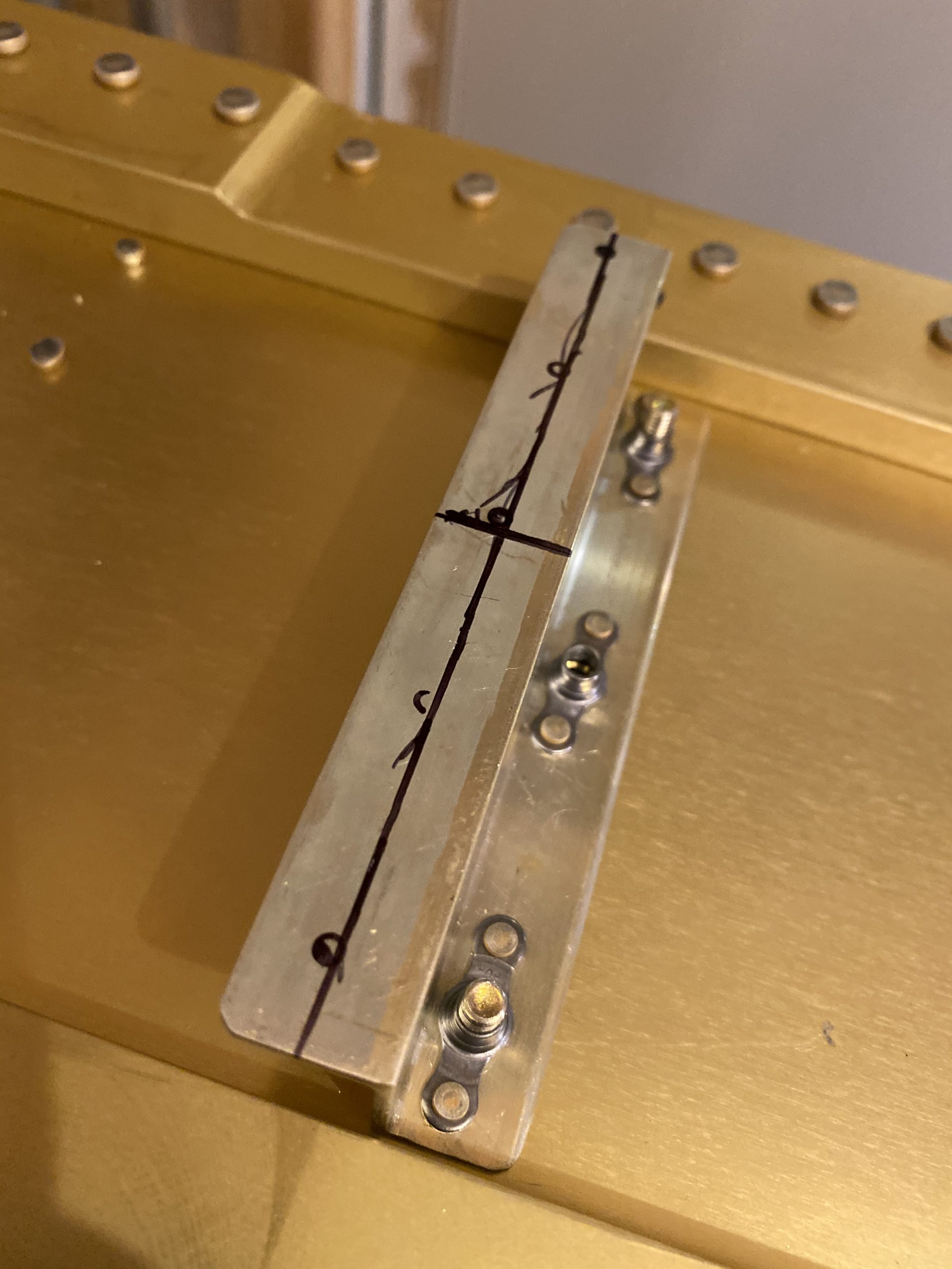
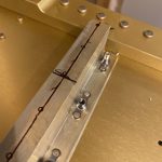
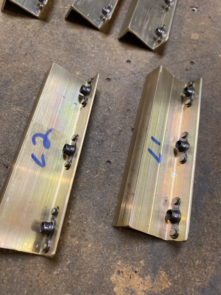
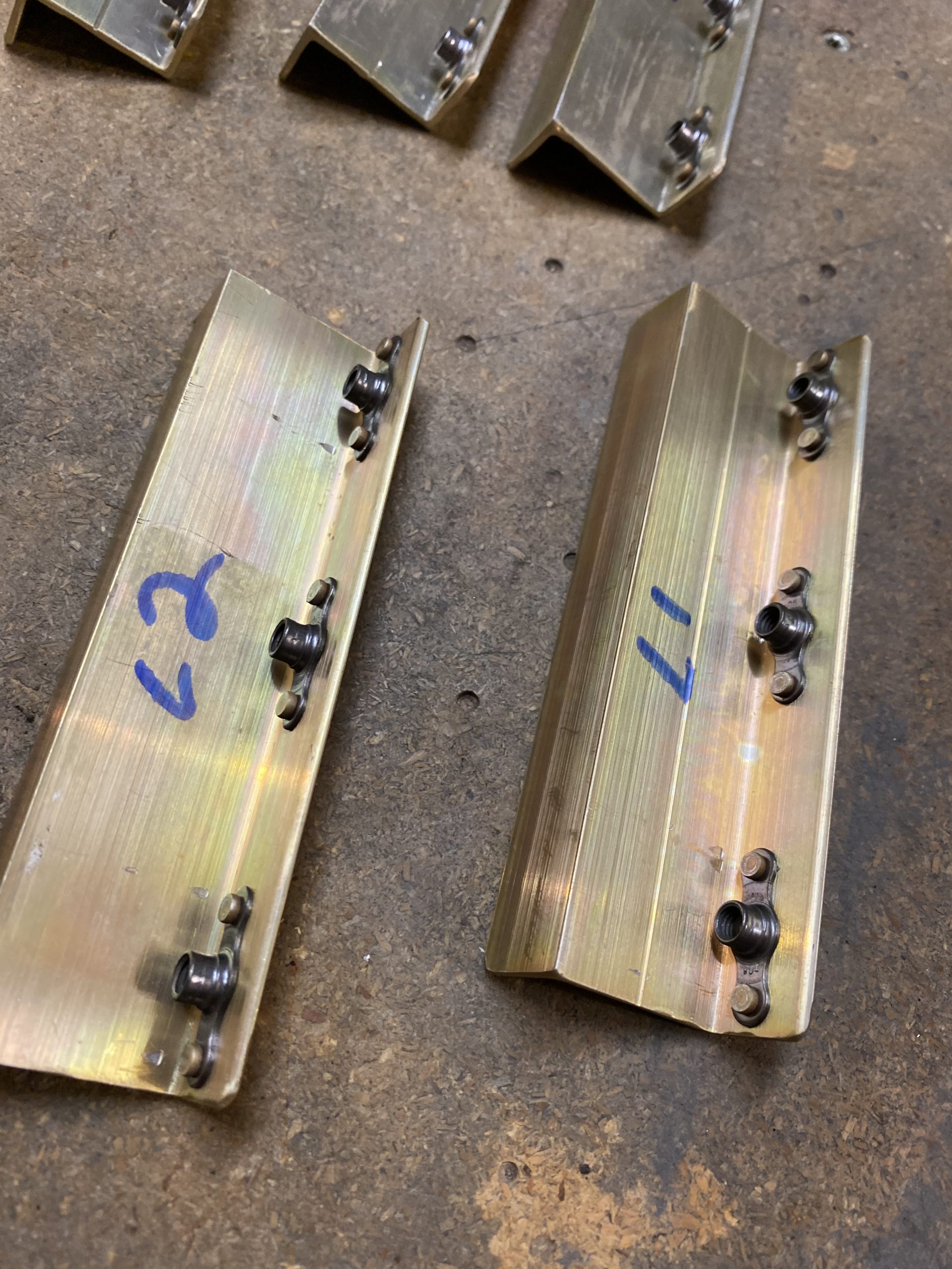
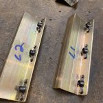
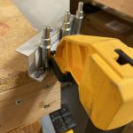
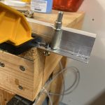
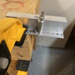
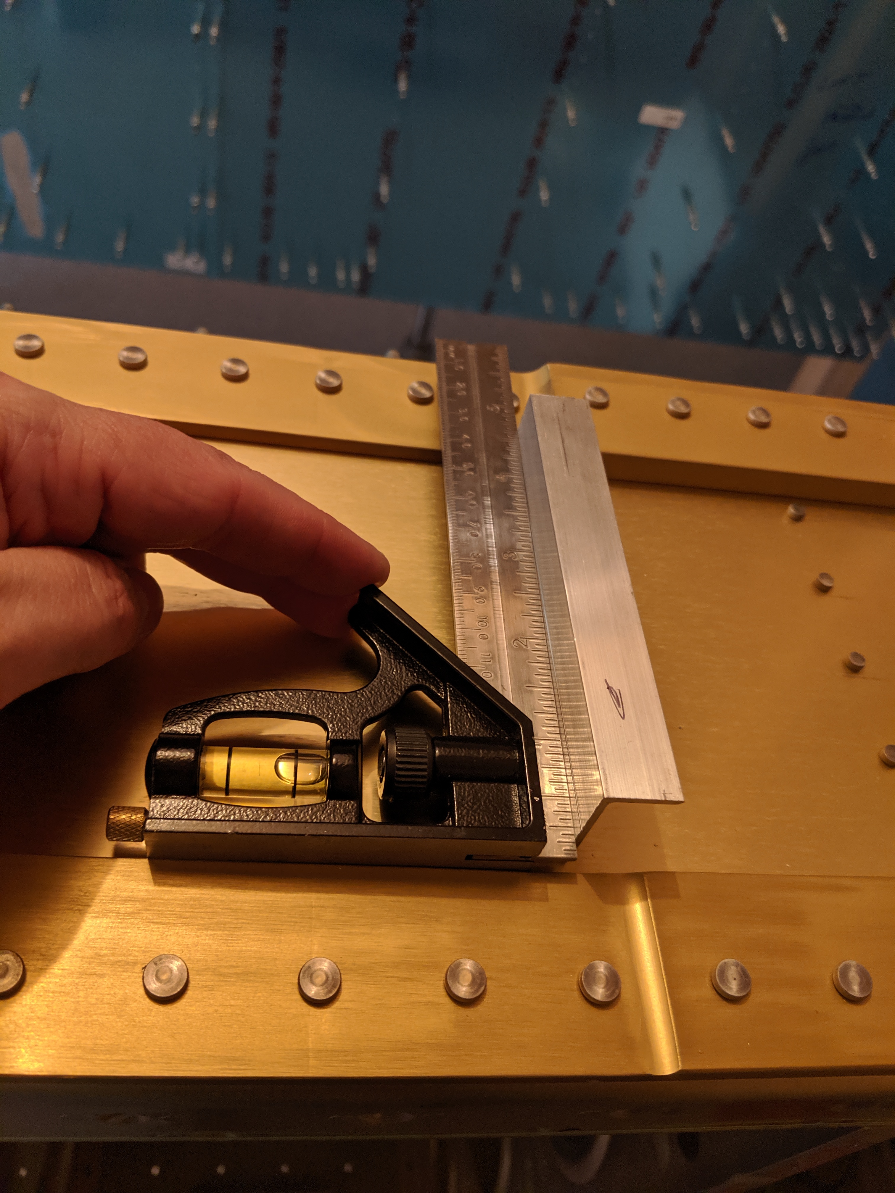
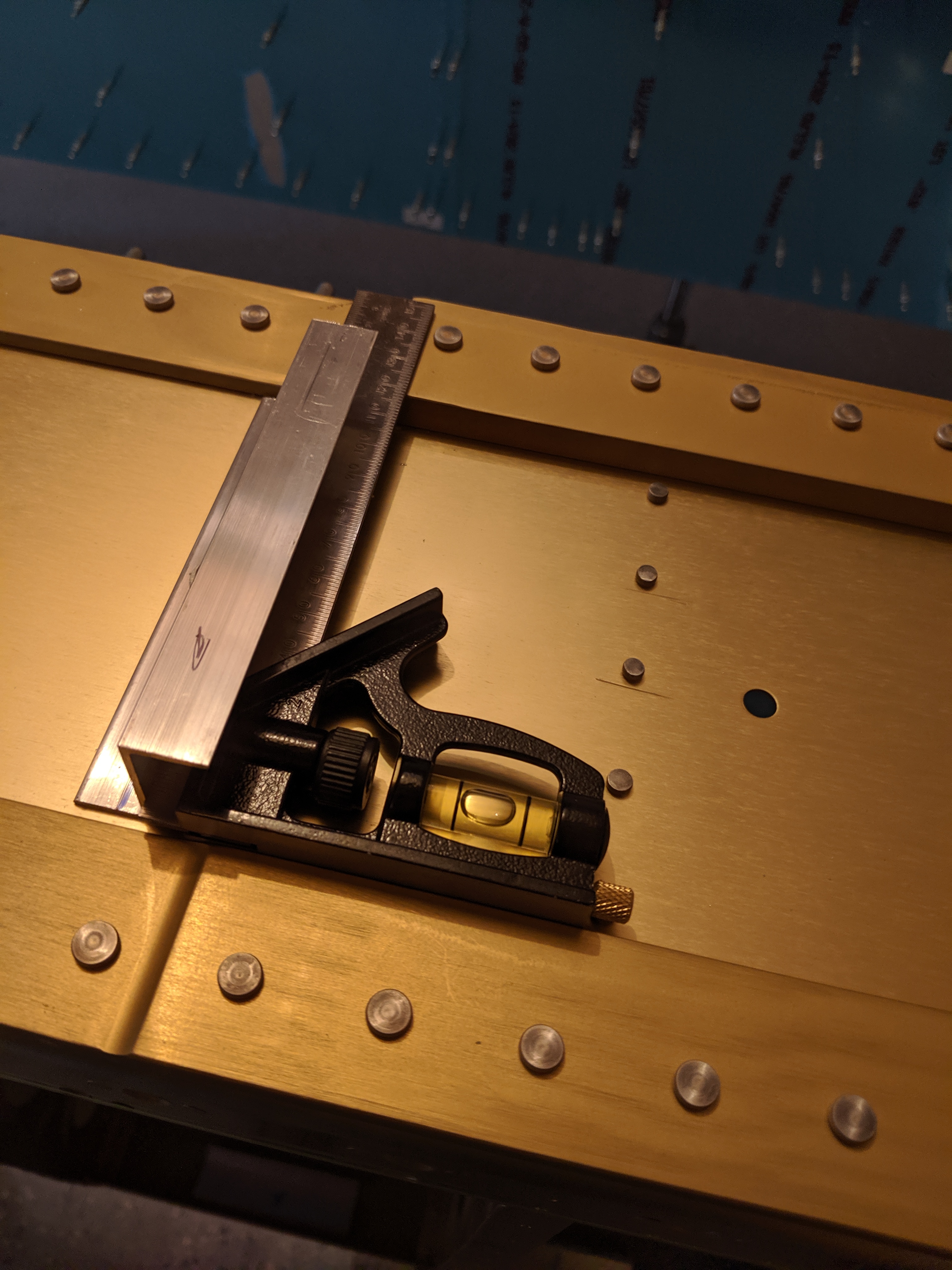
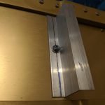
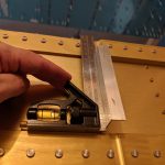
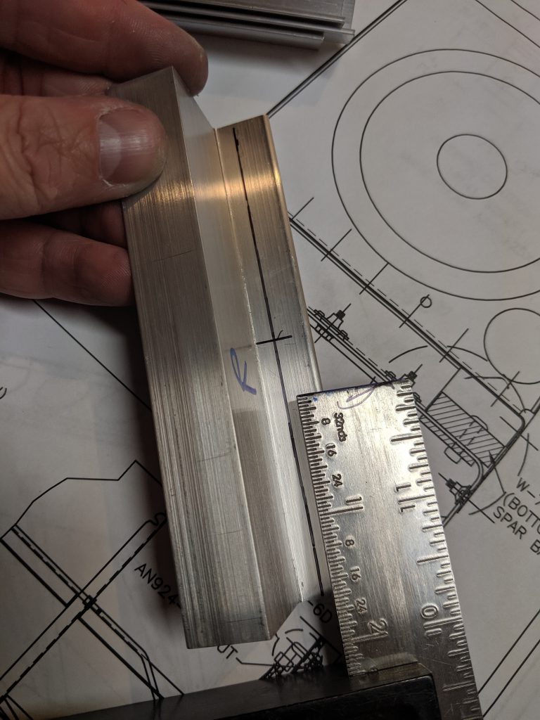
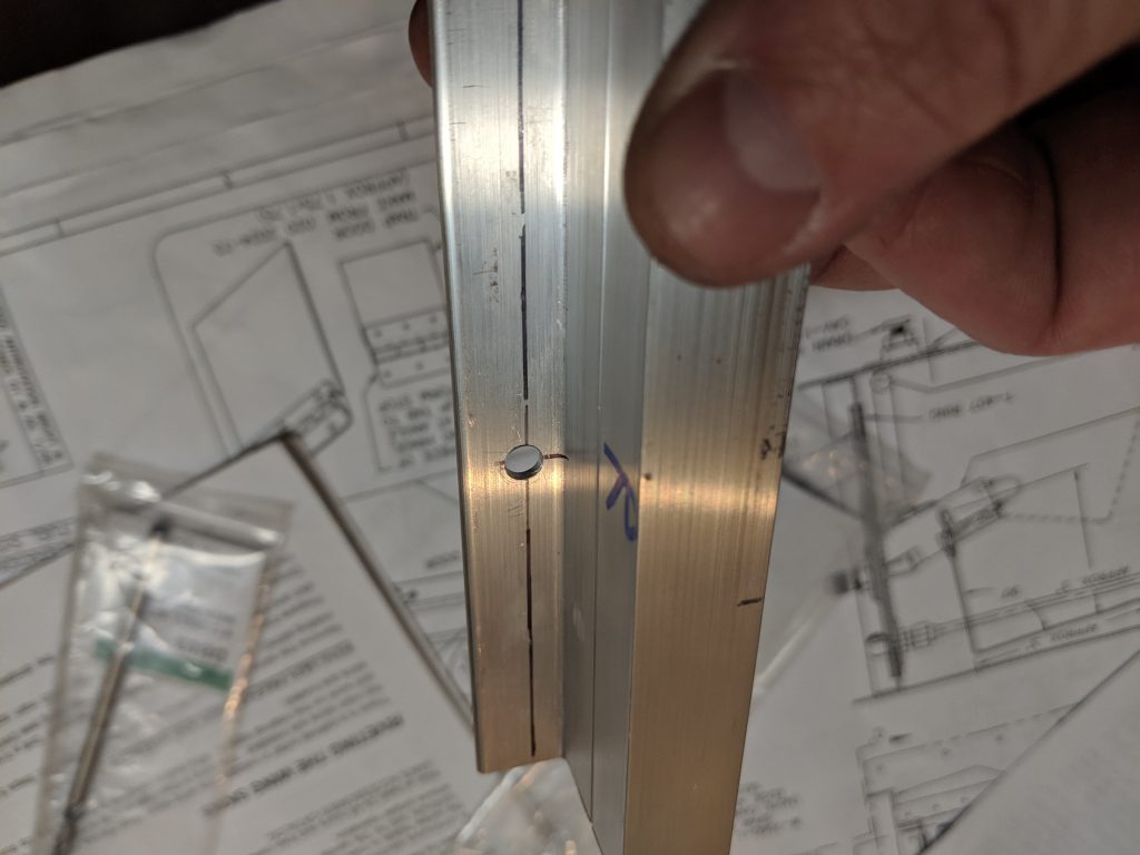
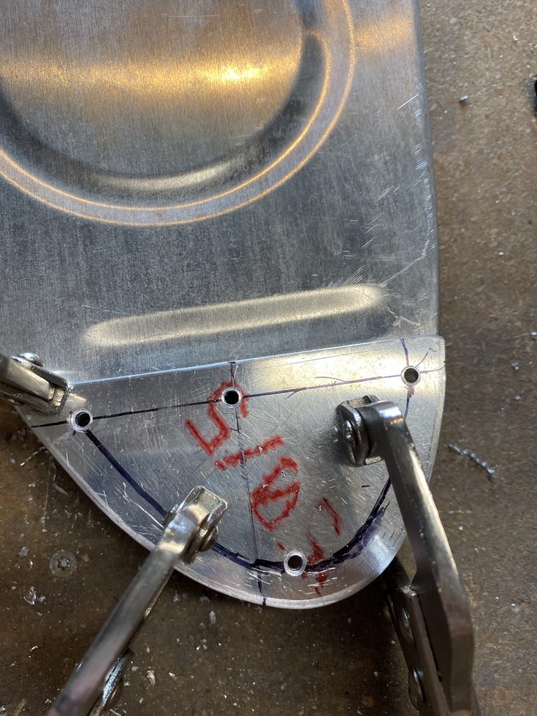
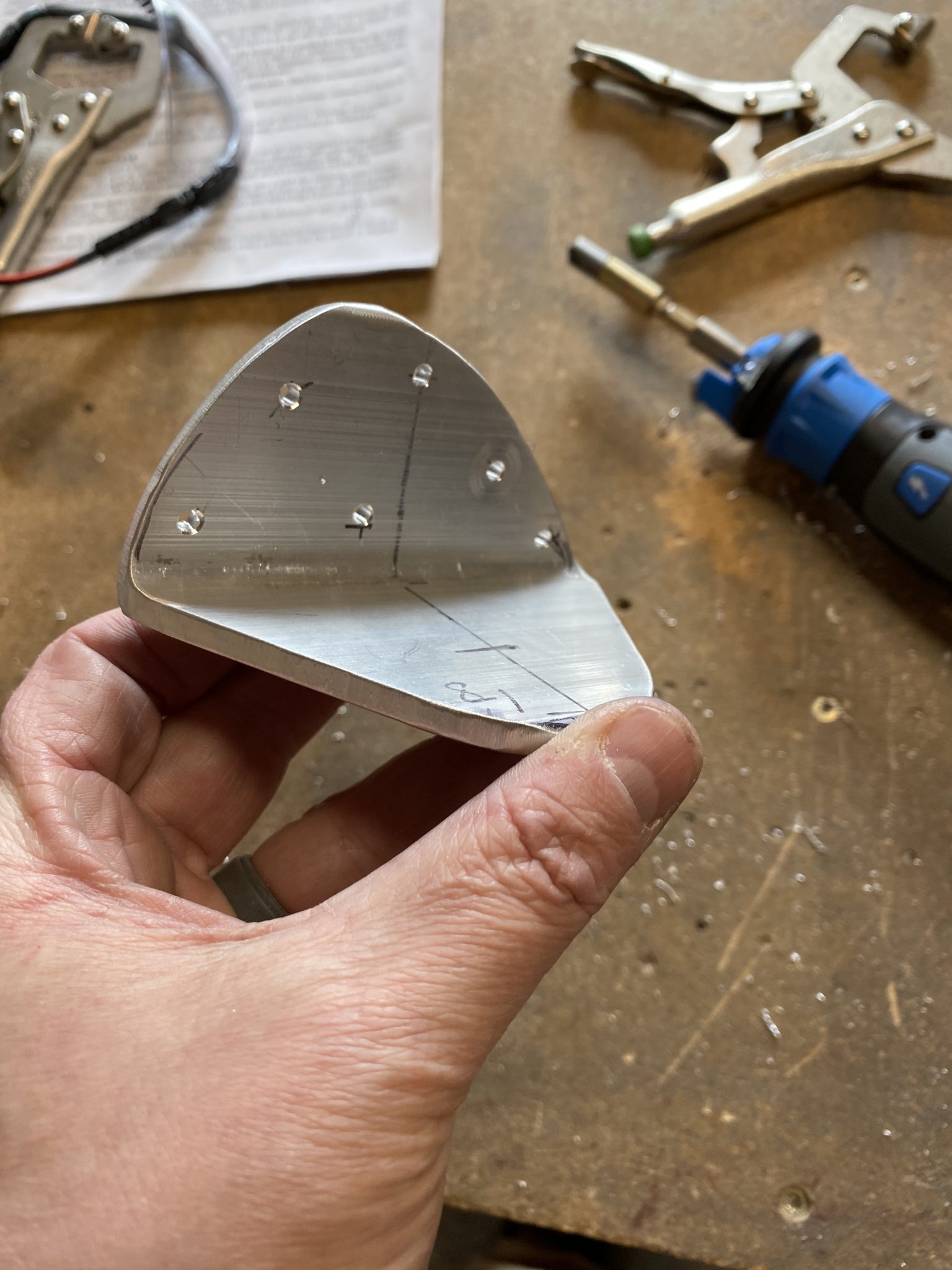
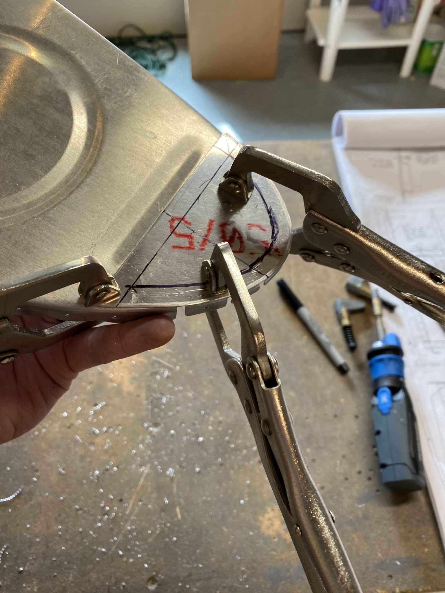
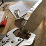
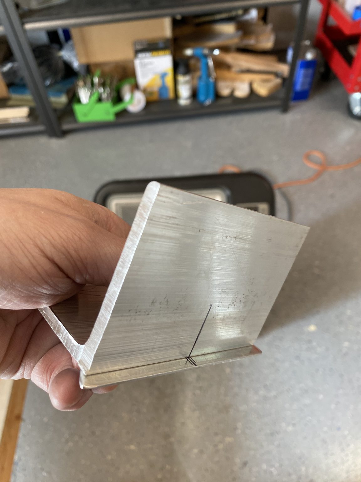
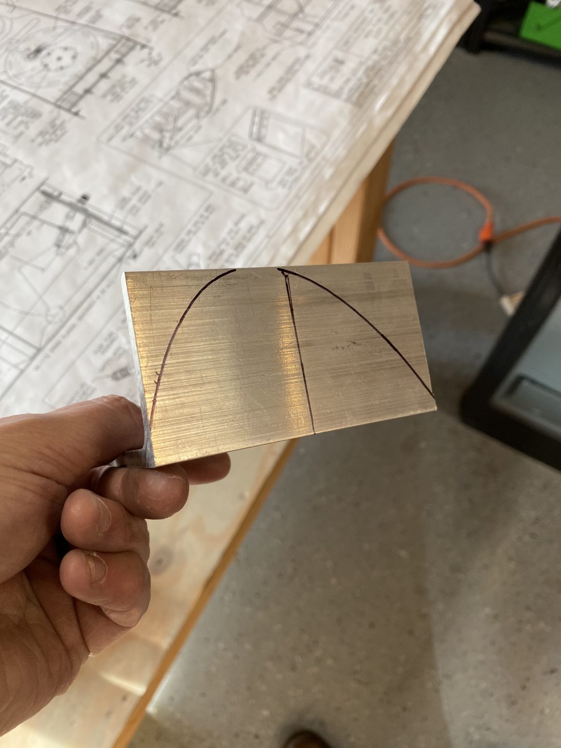
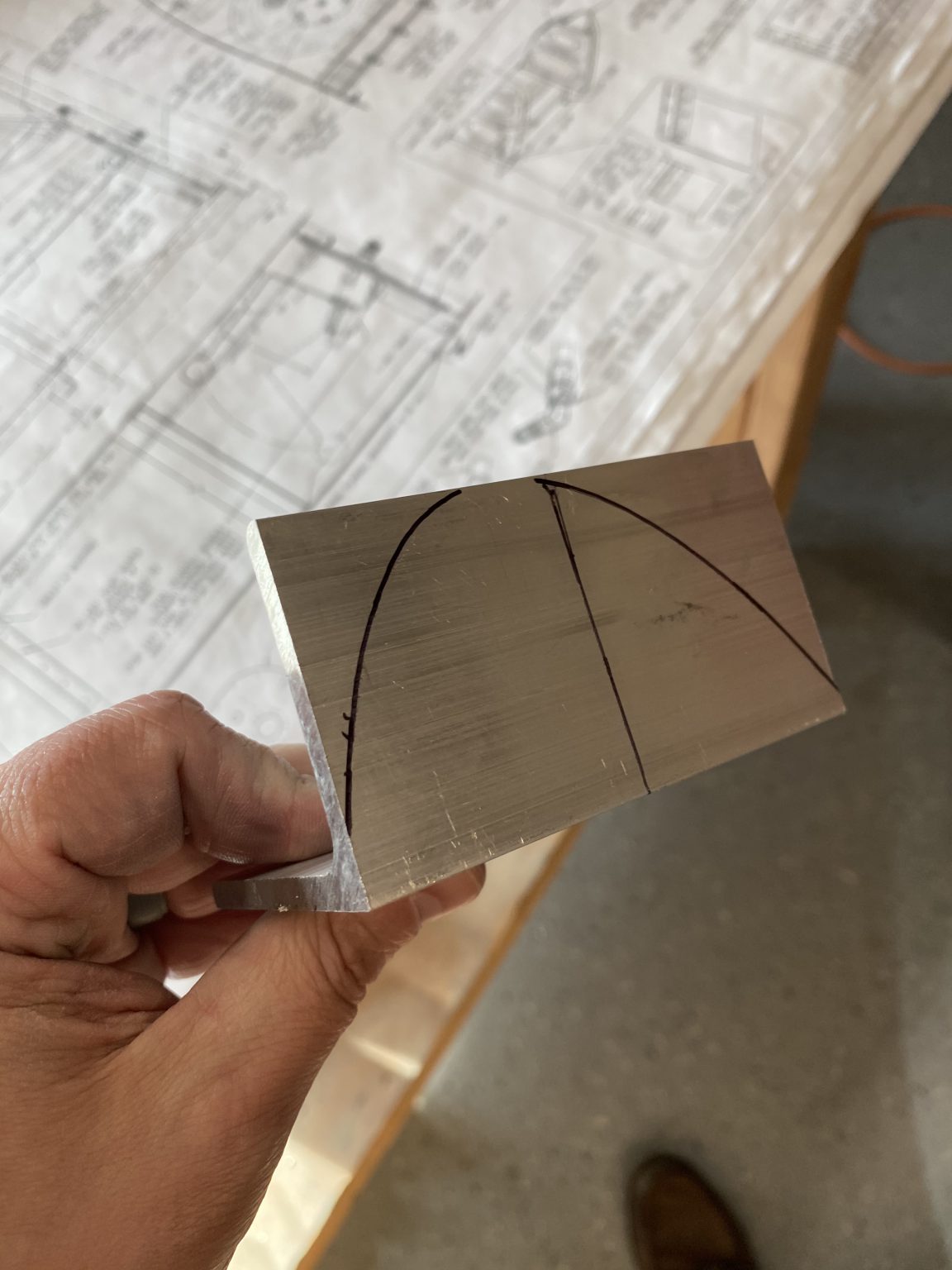
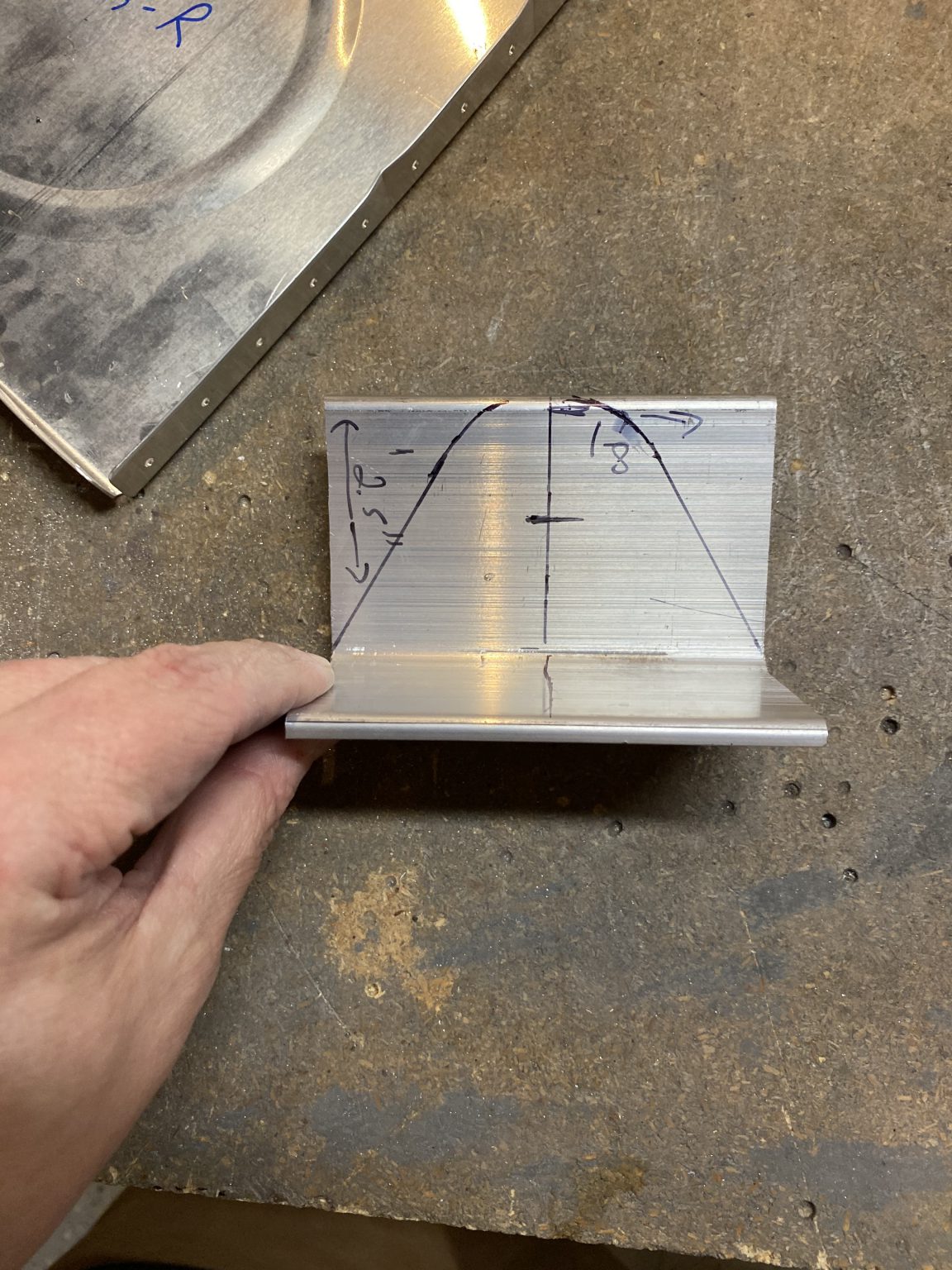
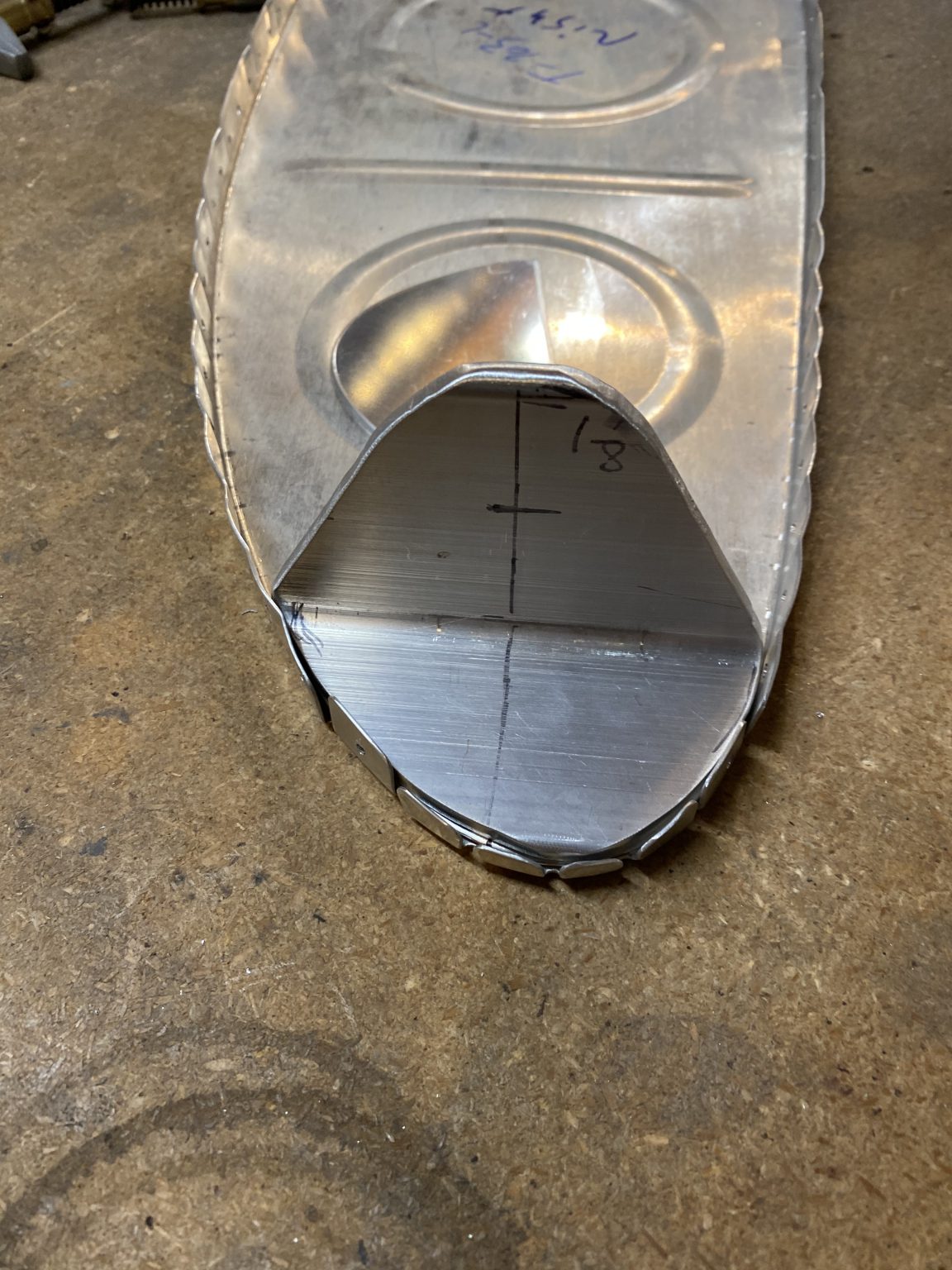
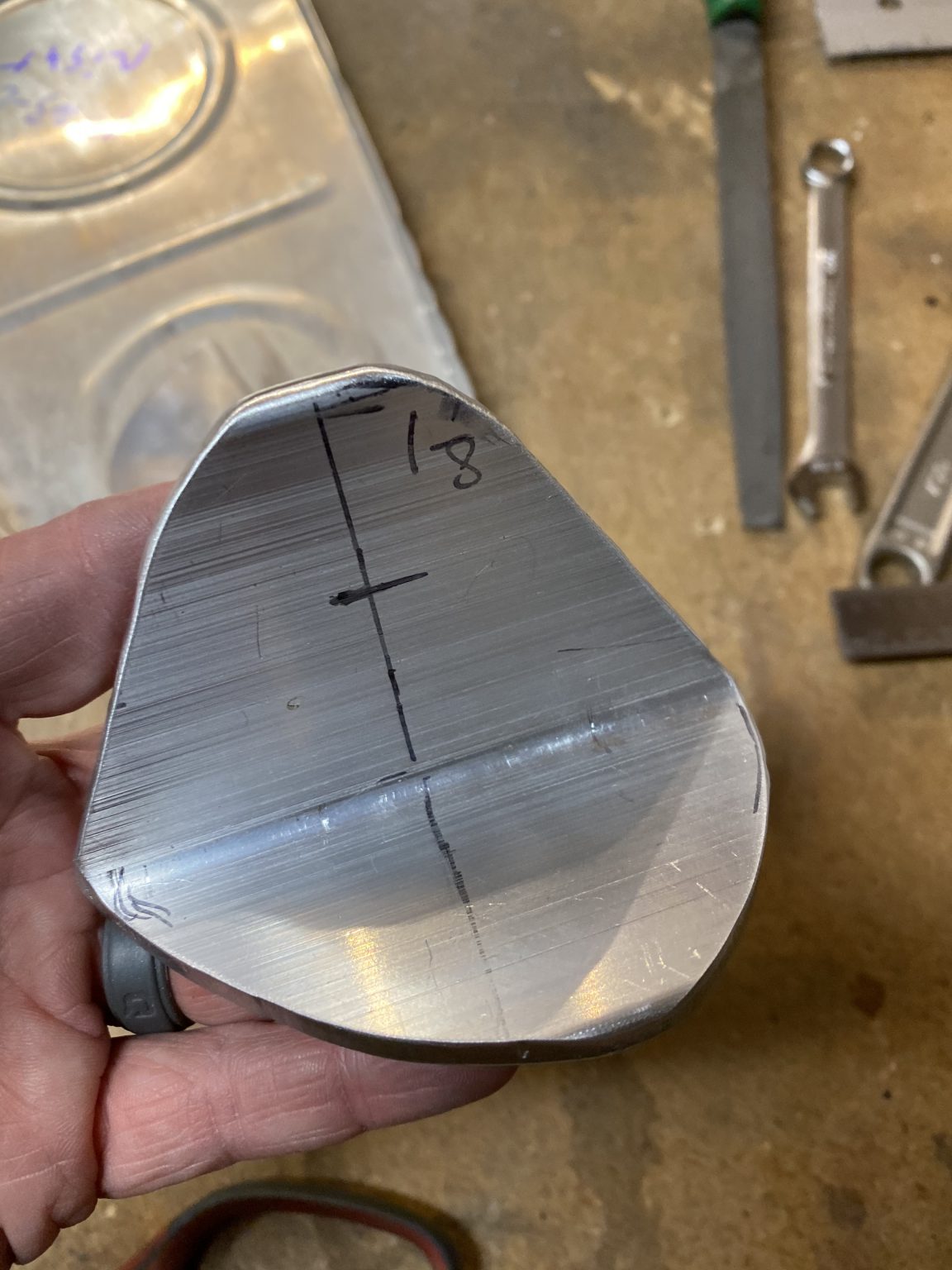
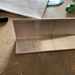
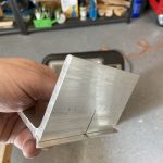
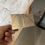
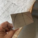
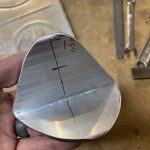
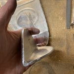
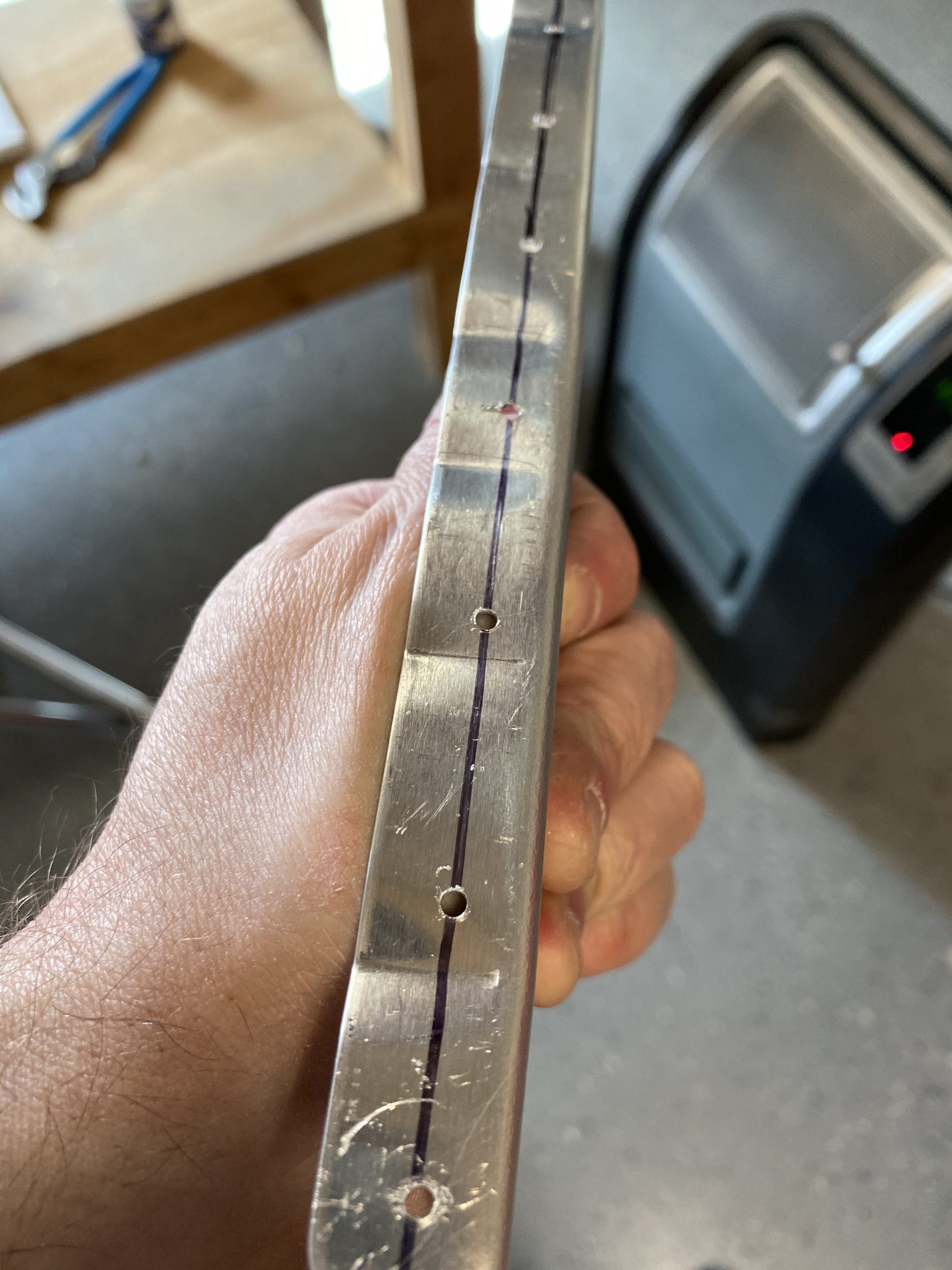
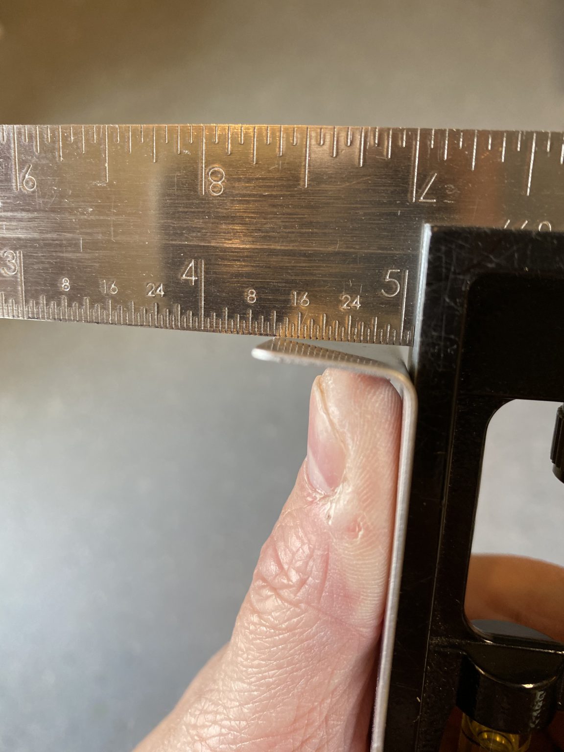
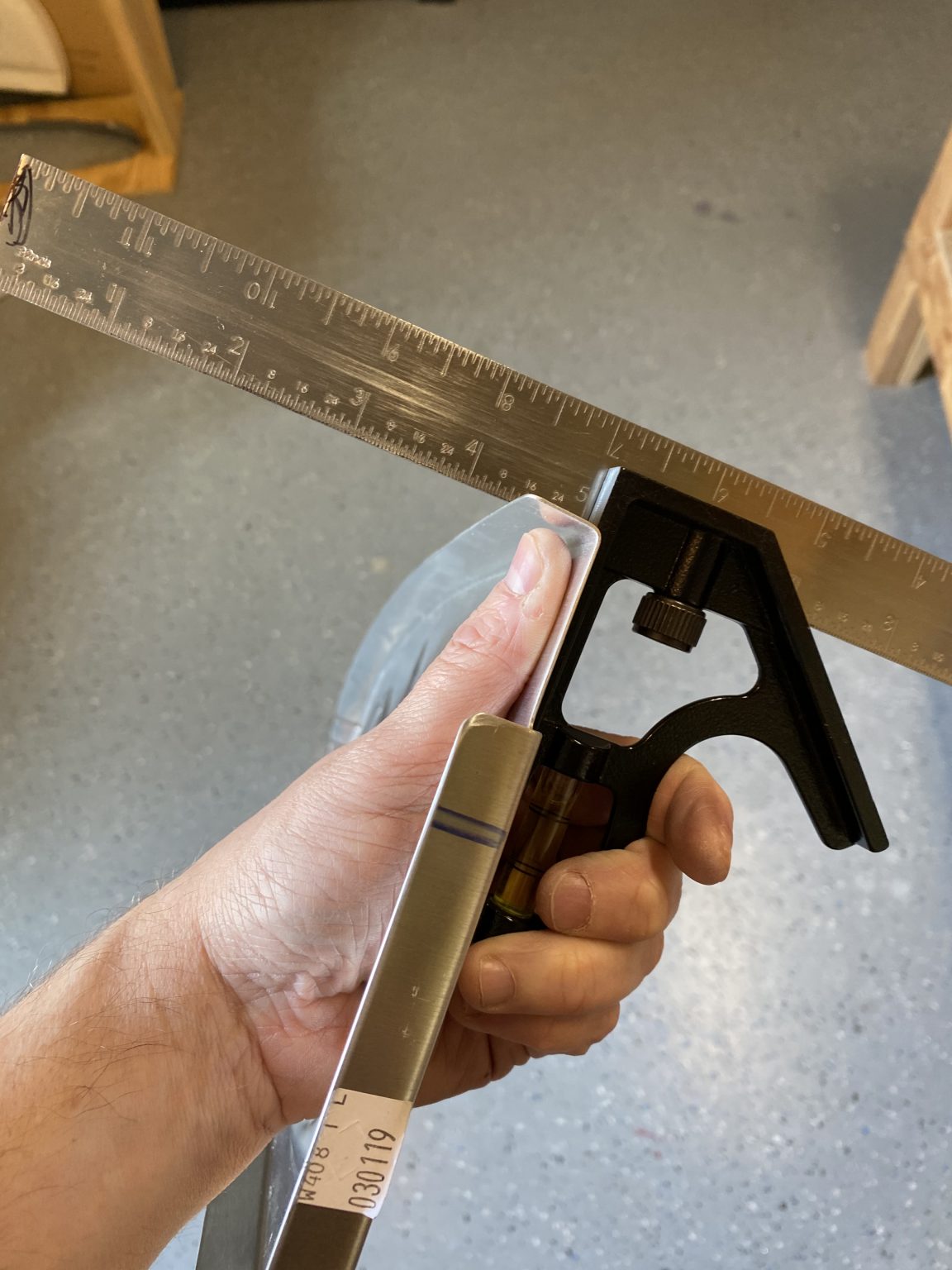
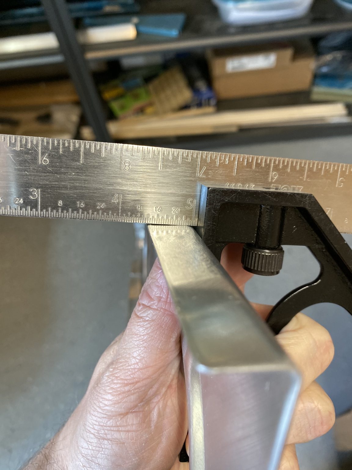
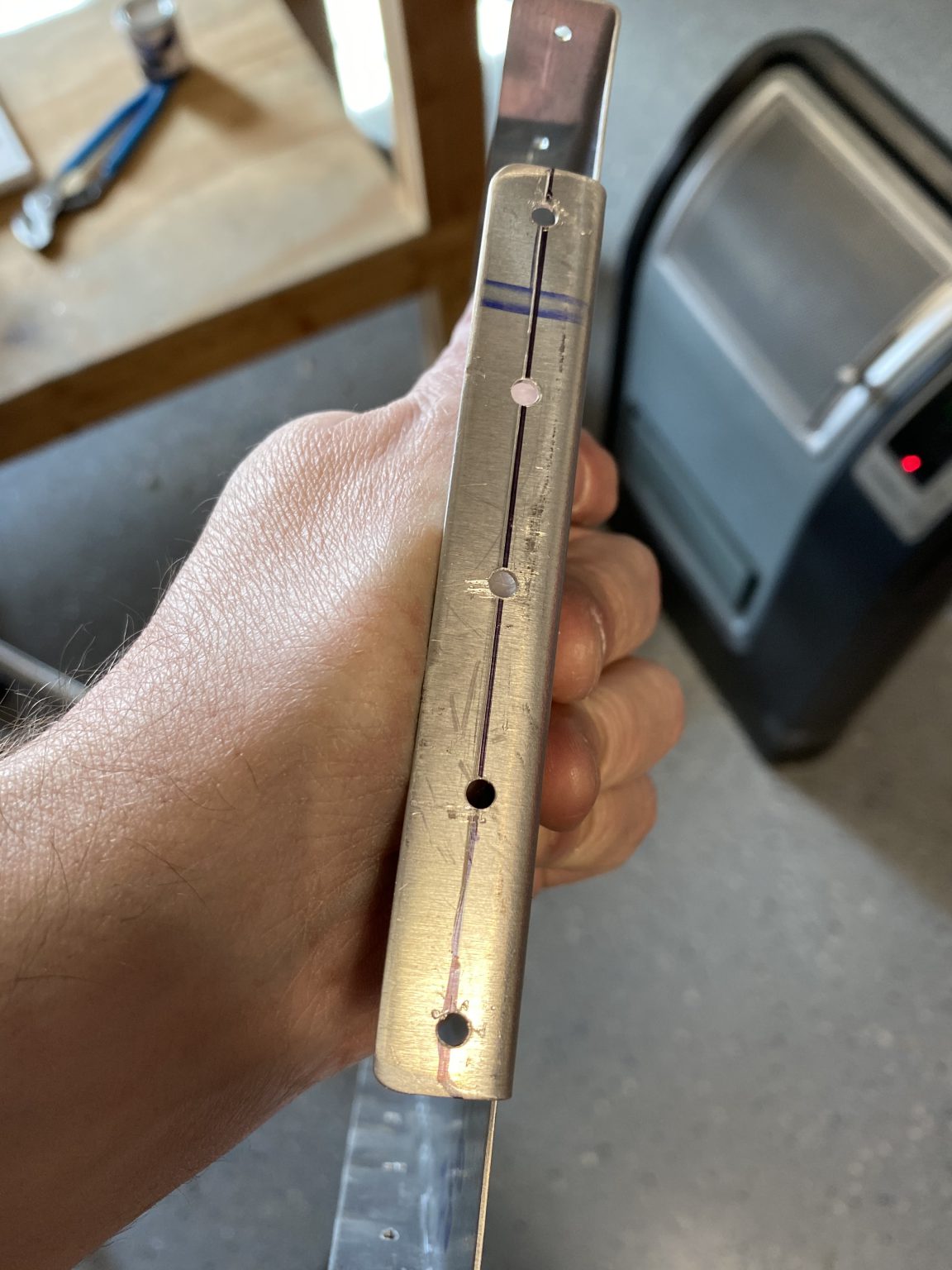
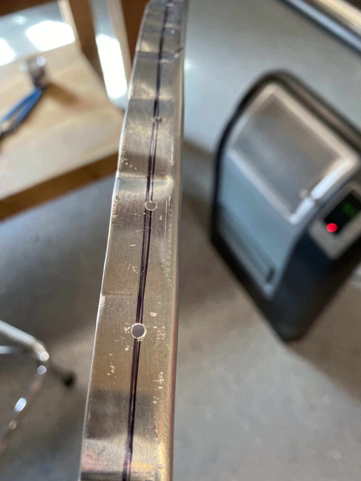
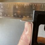
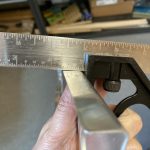
We just need to be cautious of edge distance, so I used my square and made a few lines to give me plenty of edge distance, and then drilled the brackets with a drill press to get the holes nice and straight since these are chunky bits of metal.

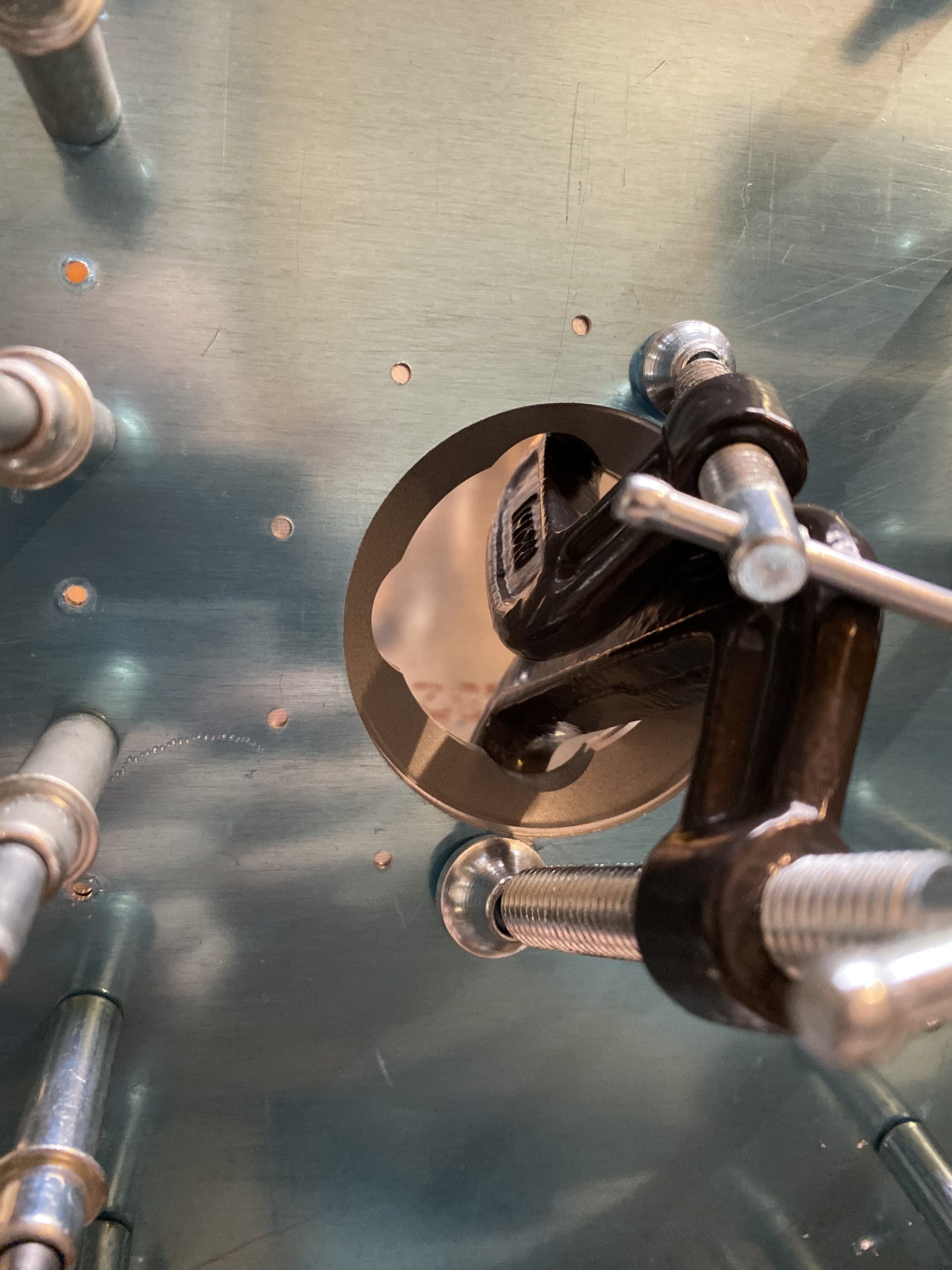
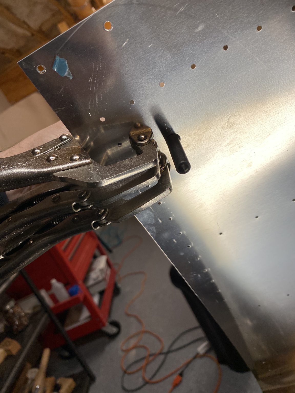
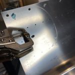
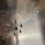
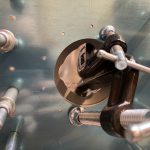
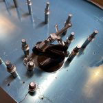
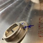
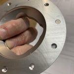
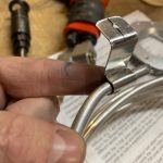
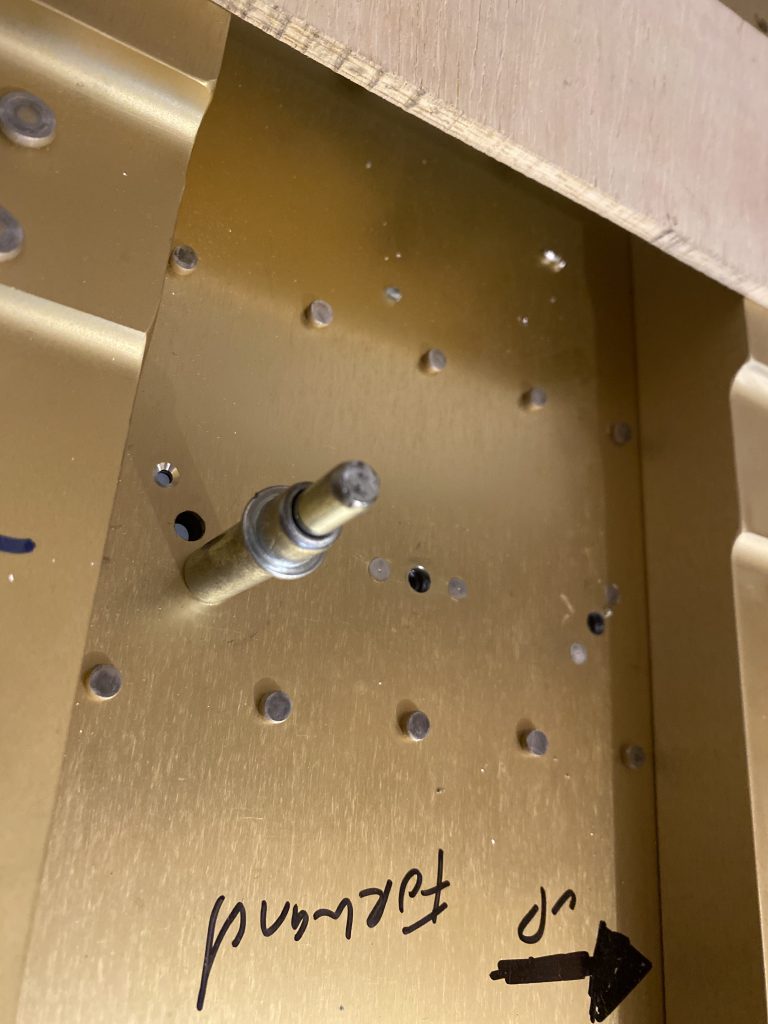
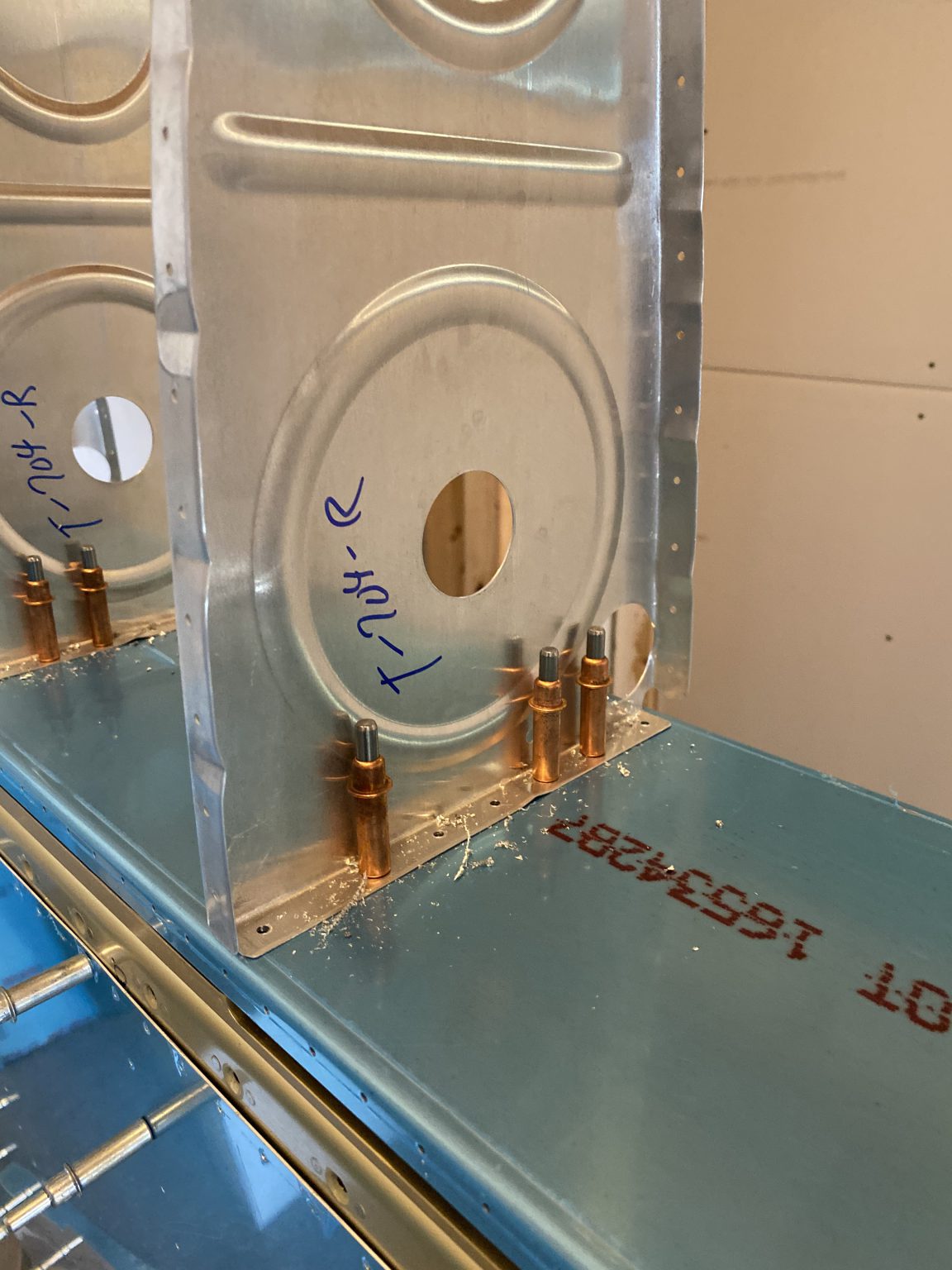
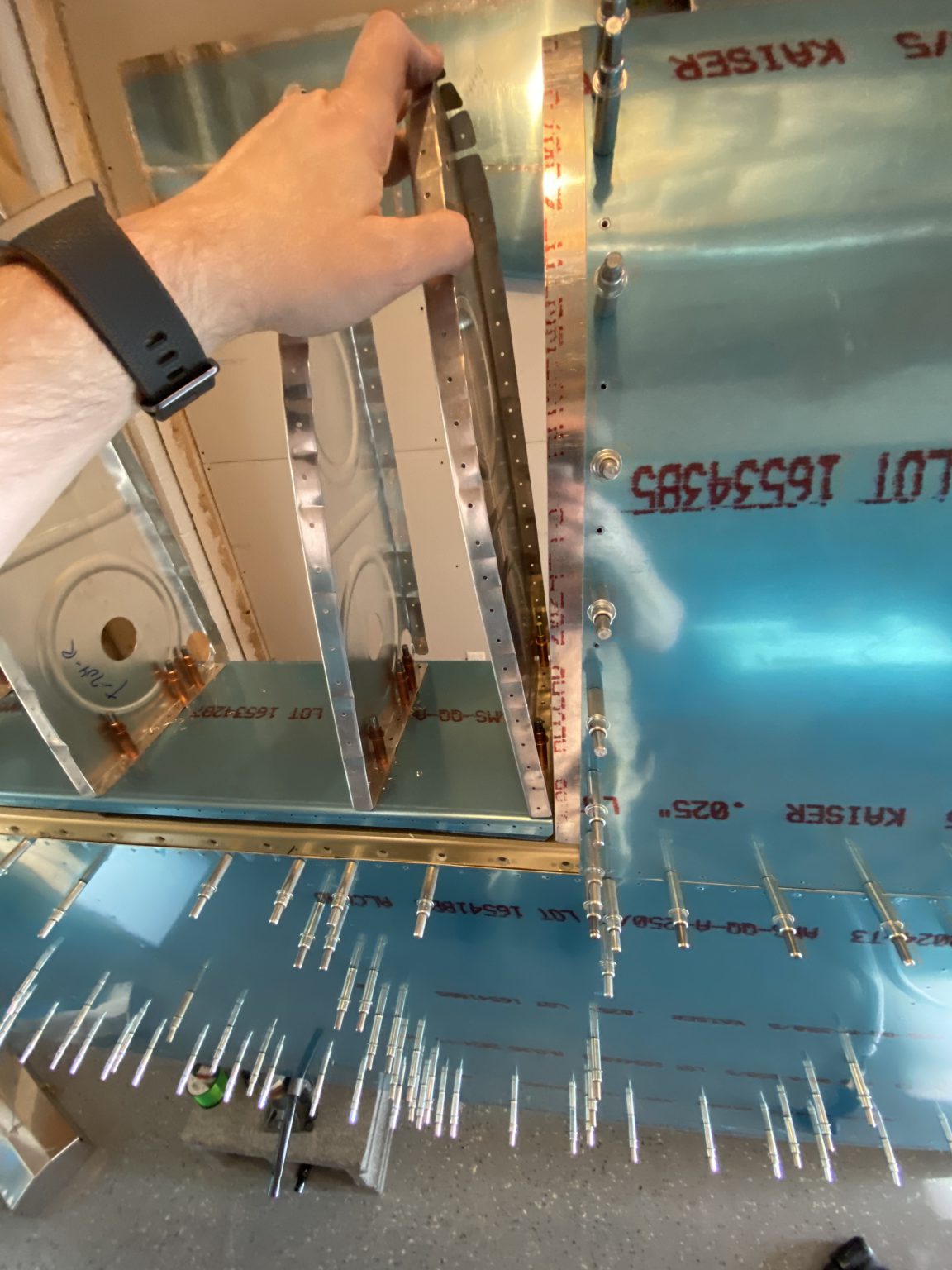
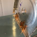
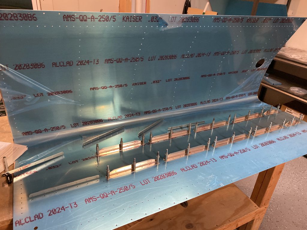
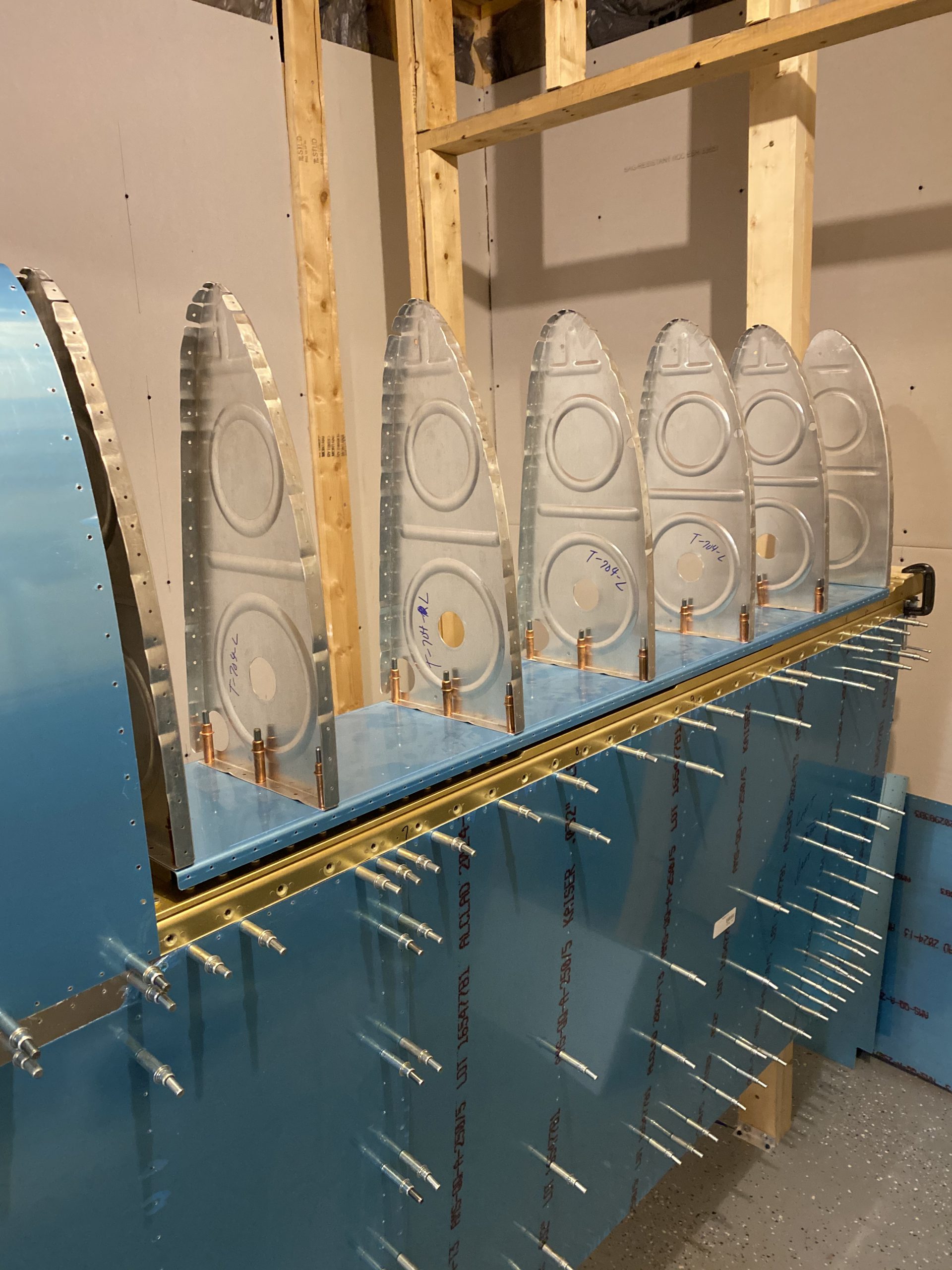
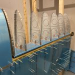
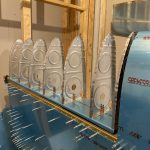
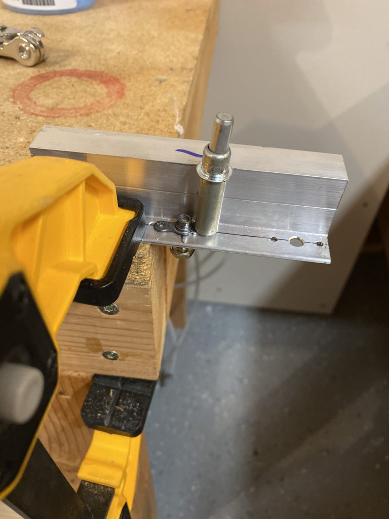
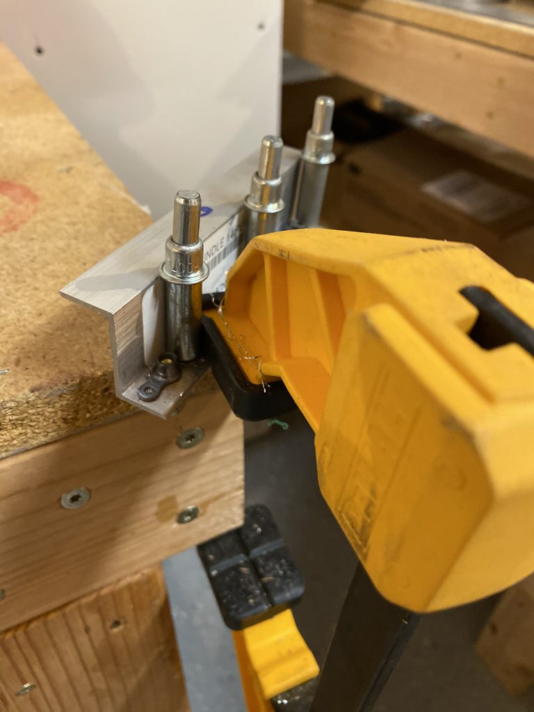
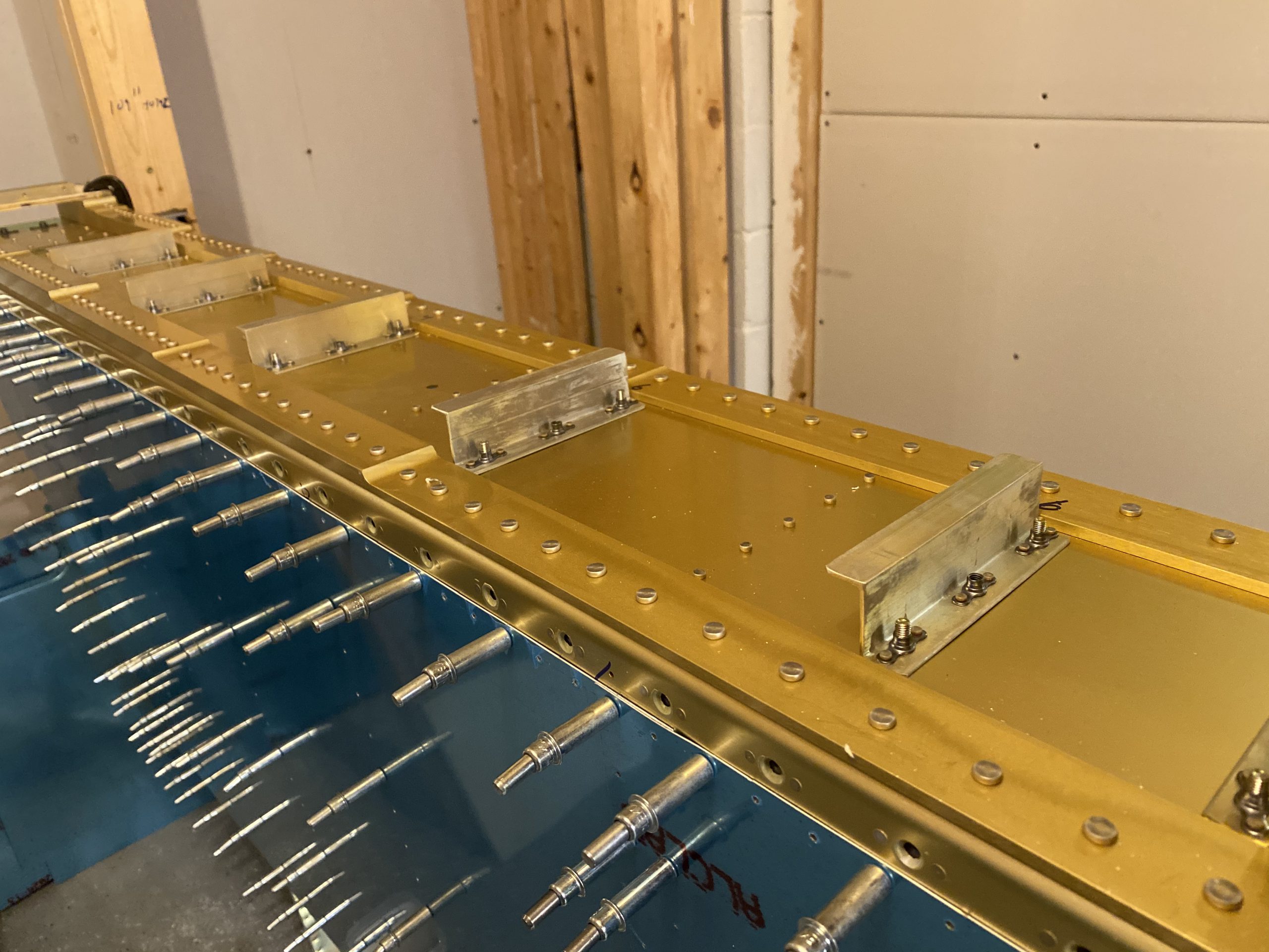
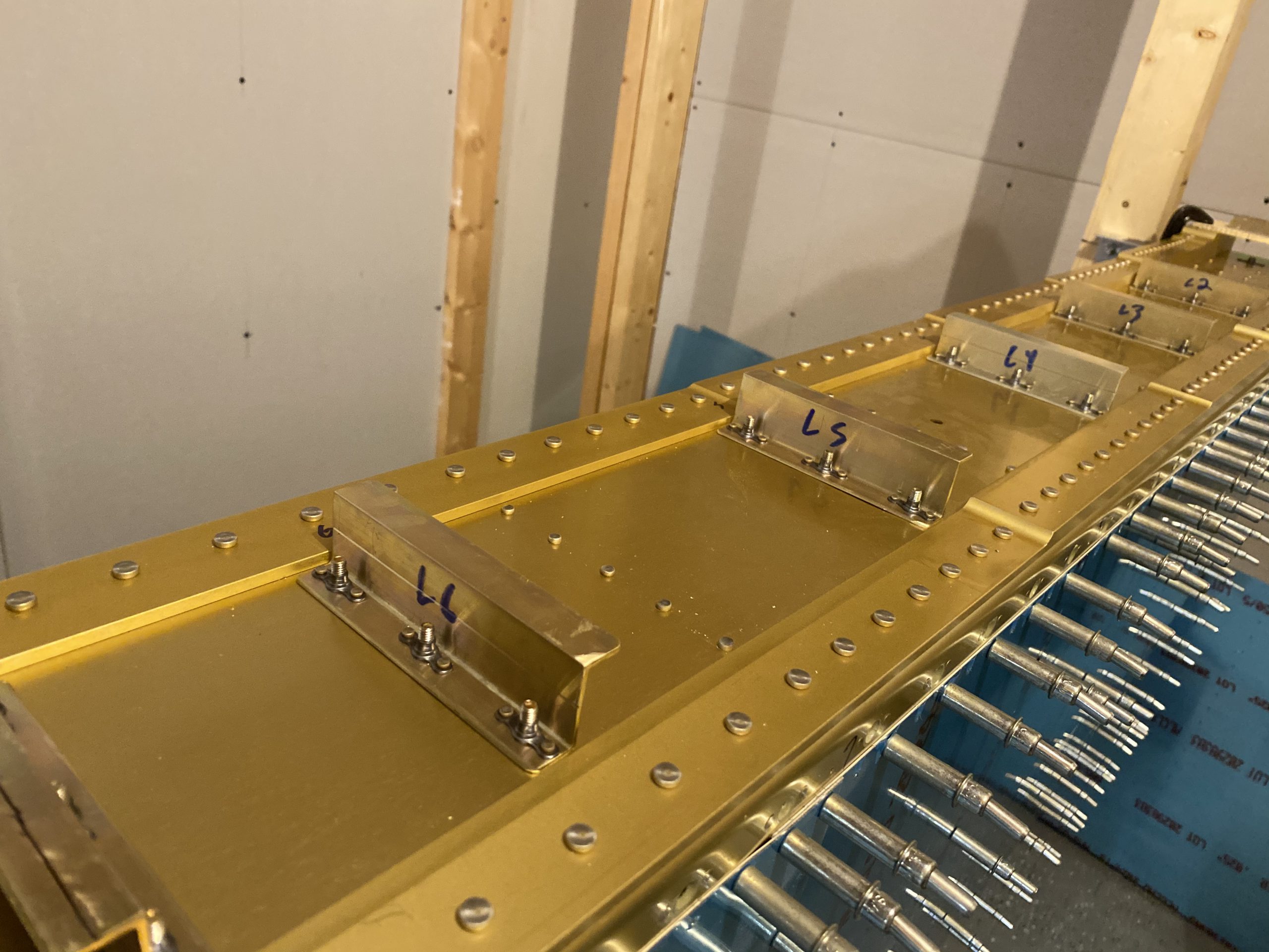
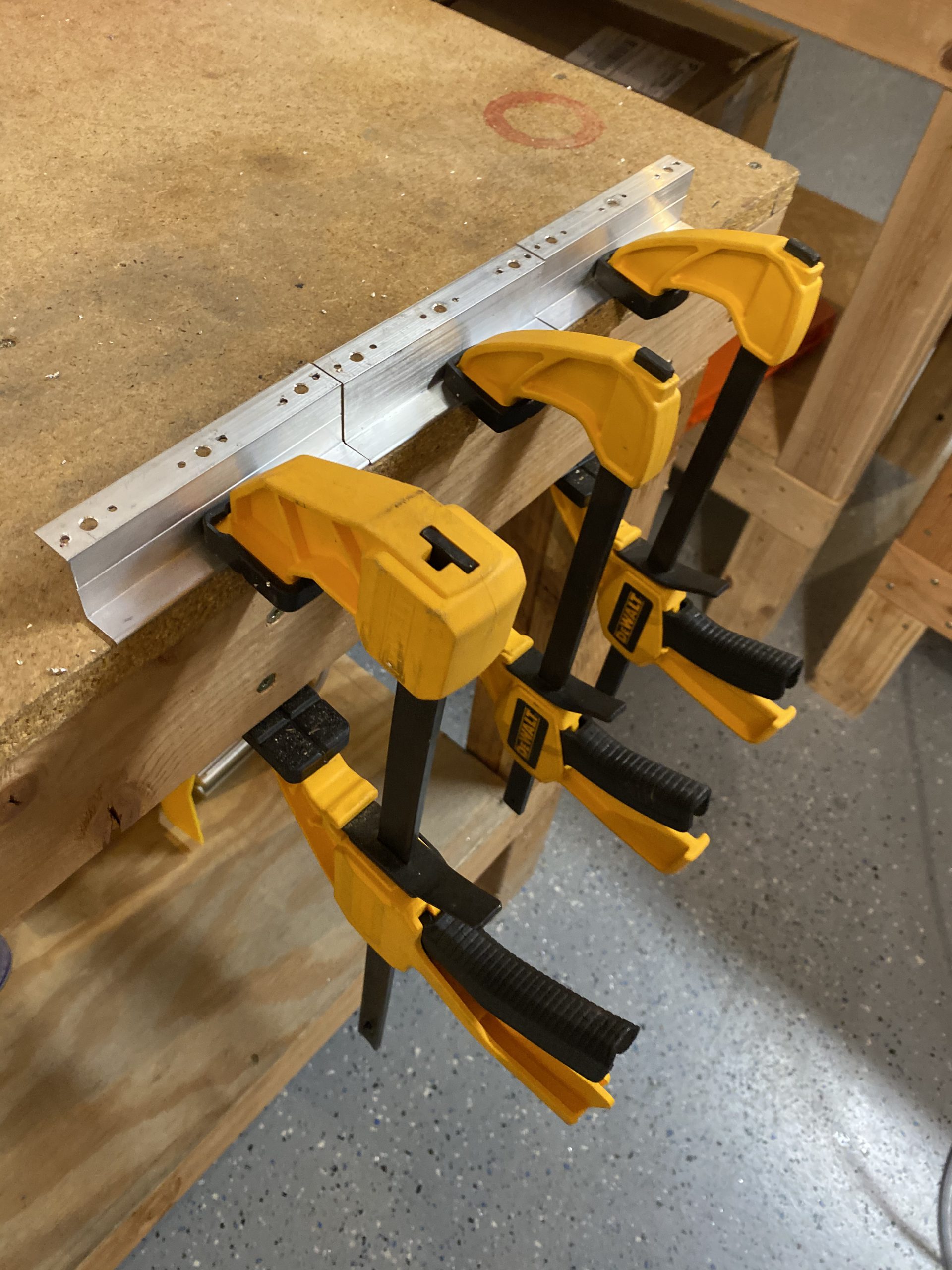
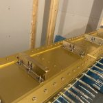
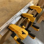
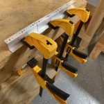
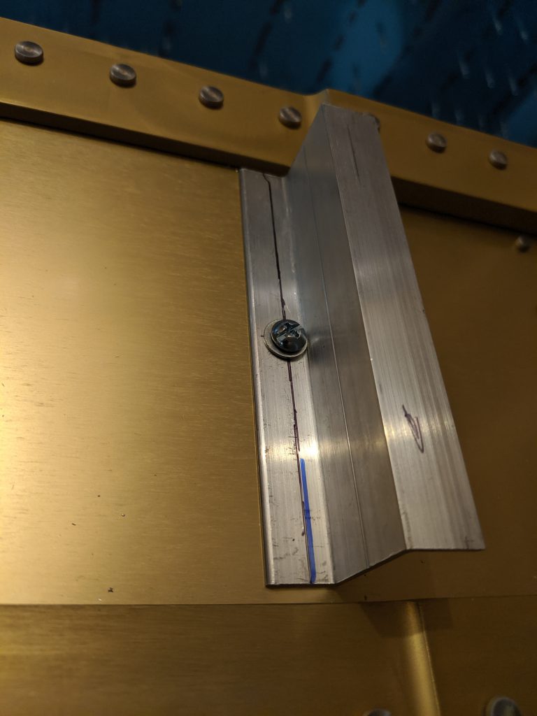
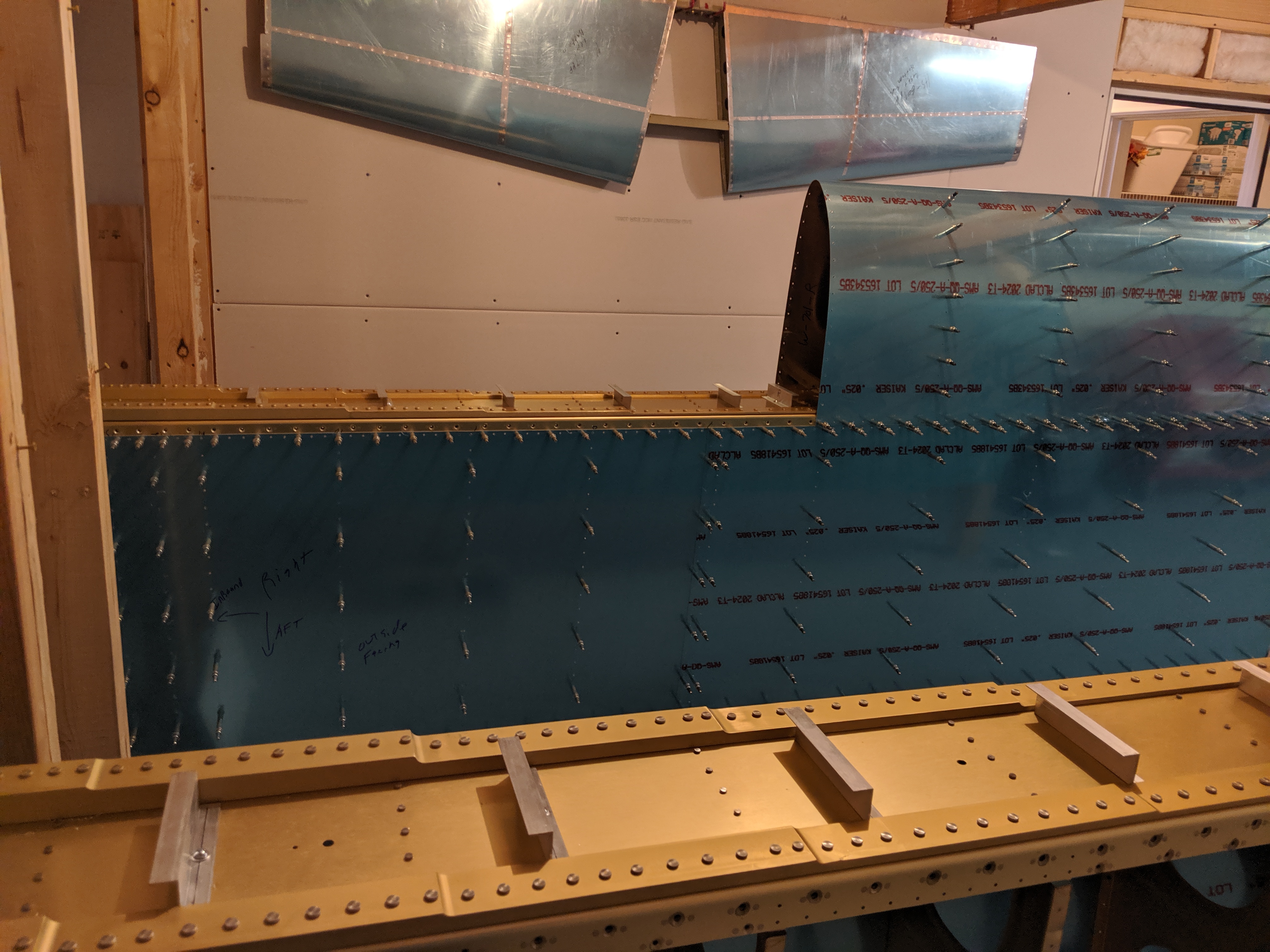
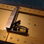
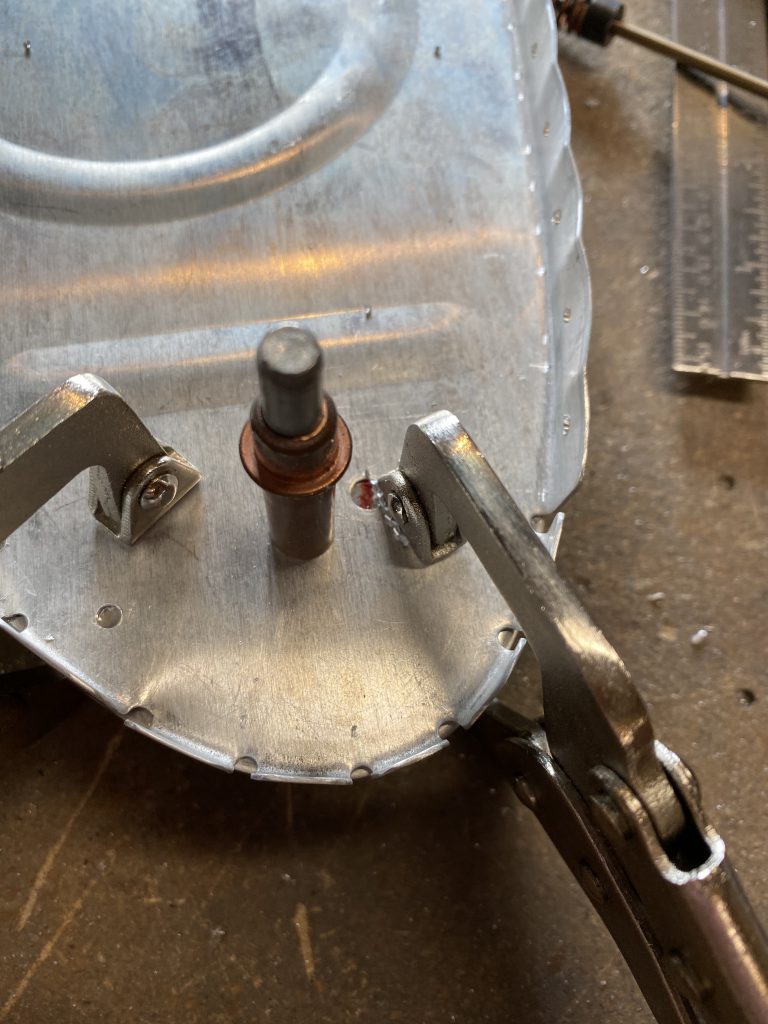
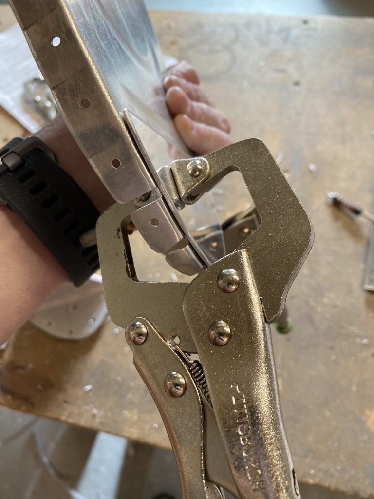
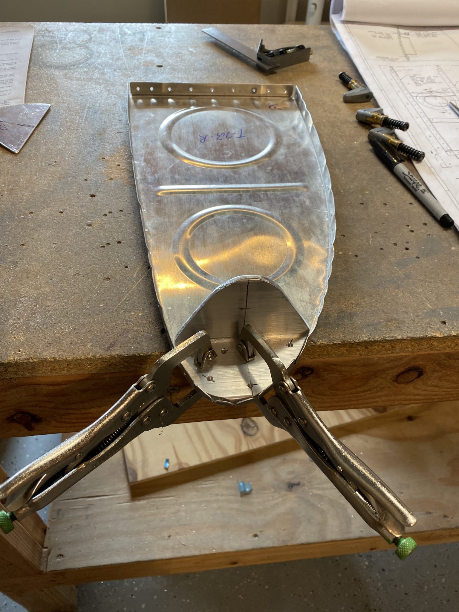
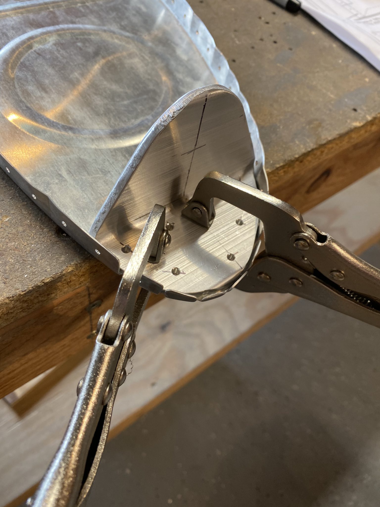
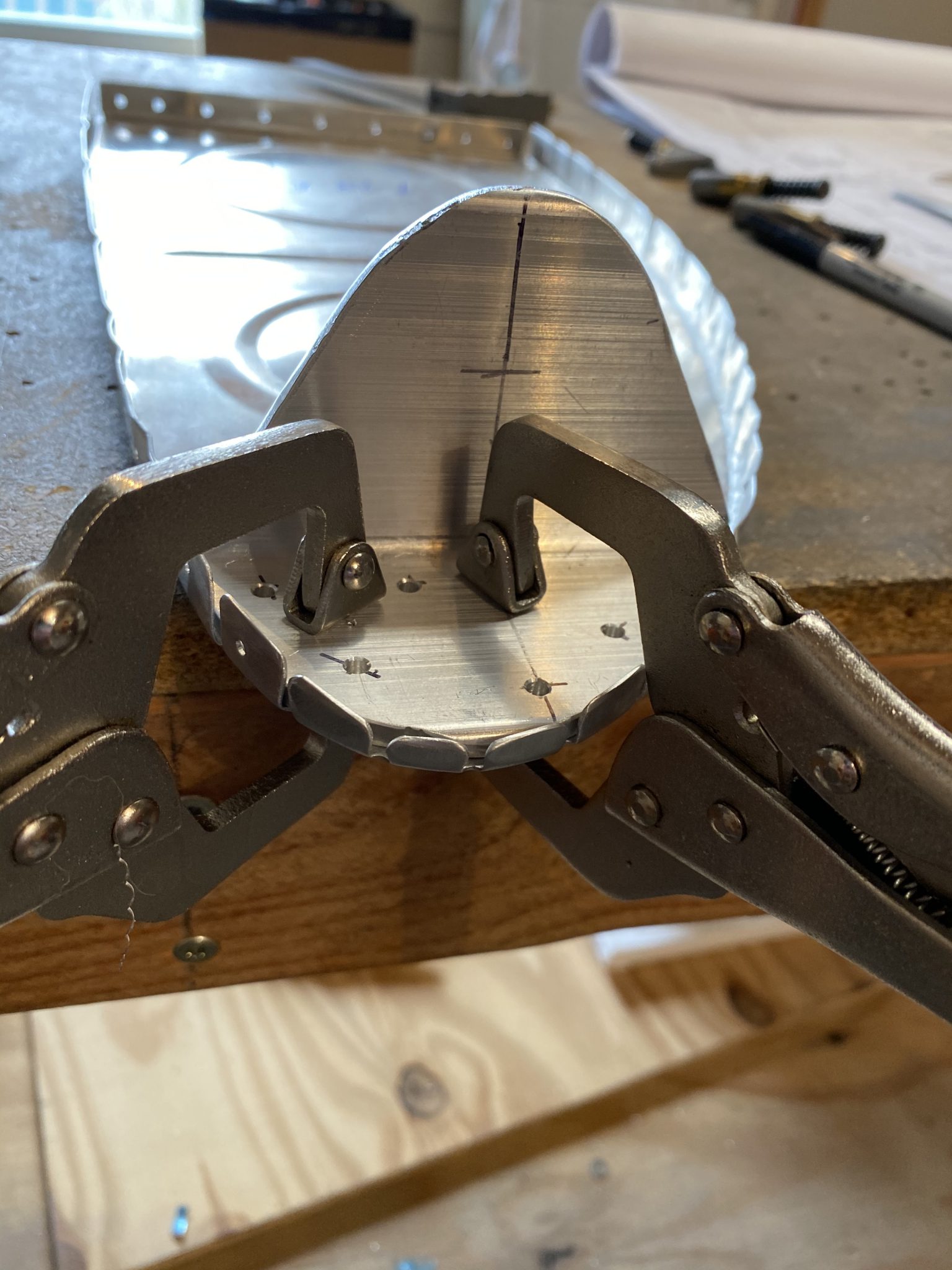
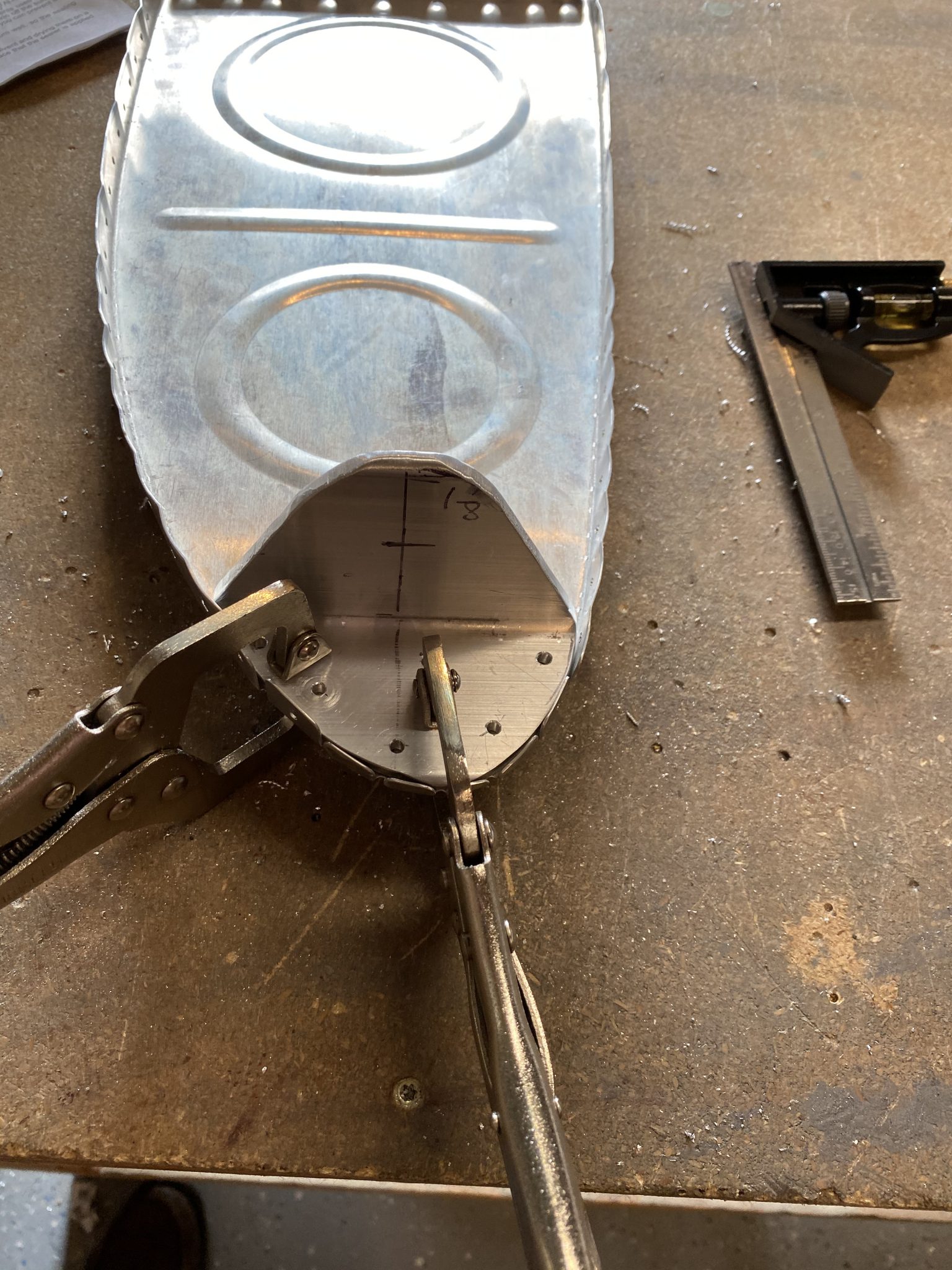
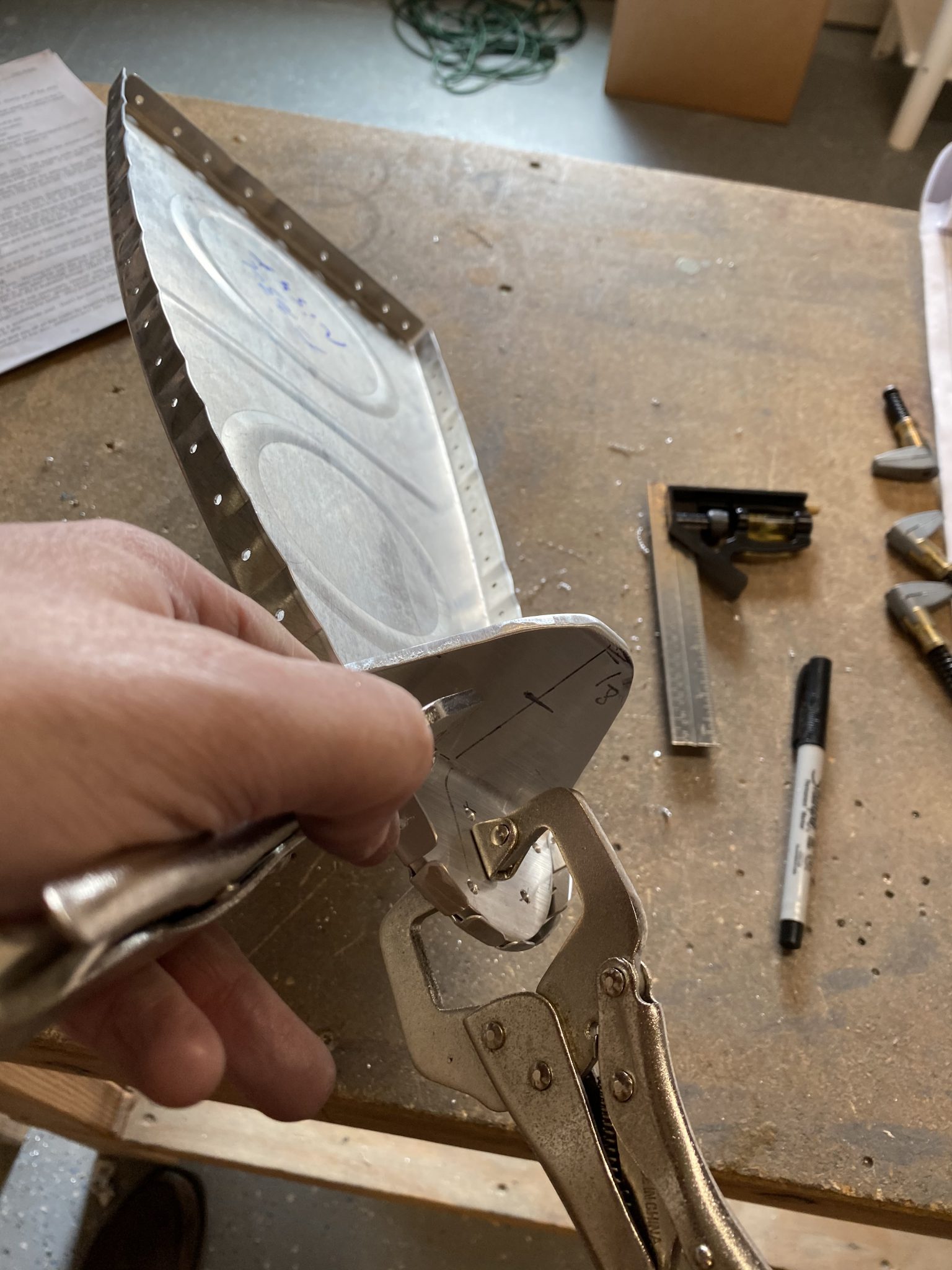
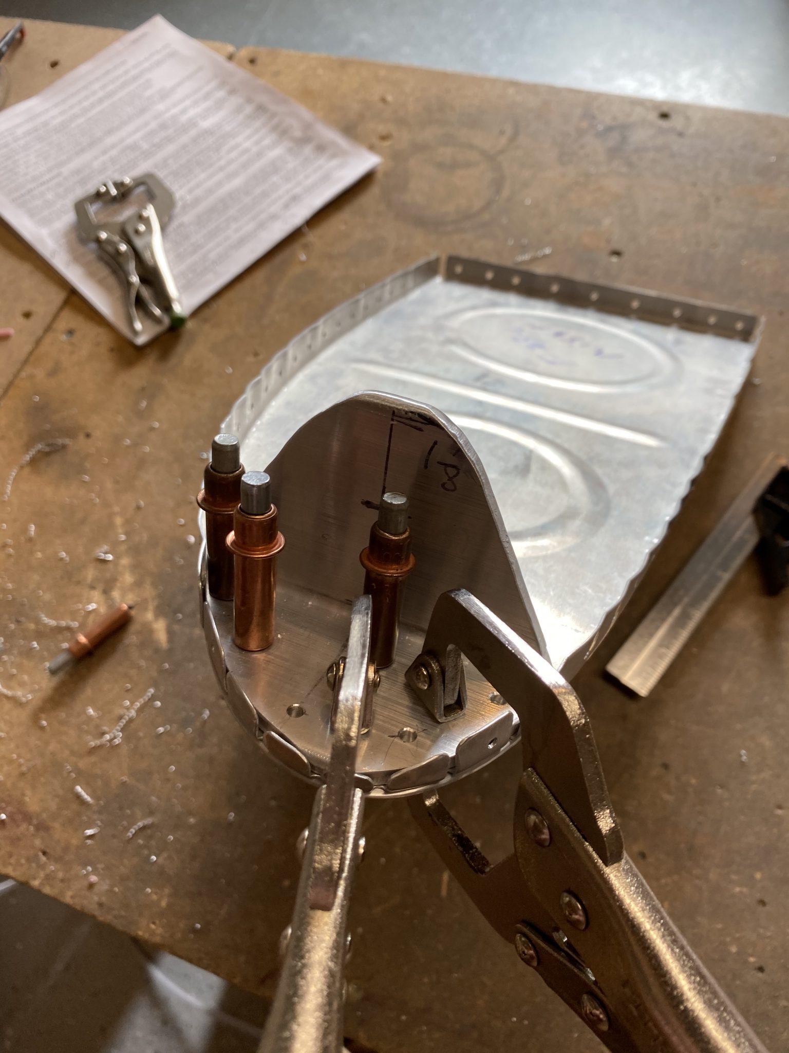
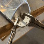
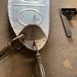
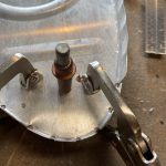
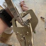
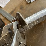
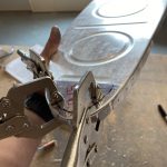
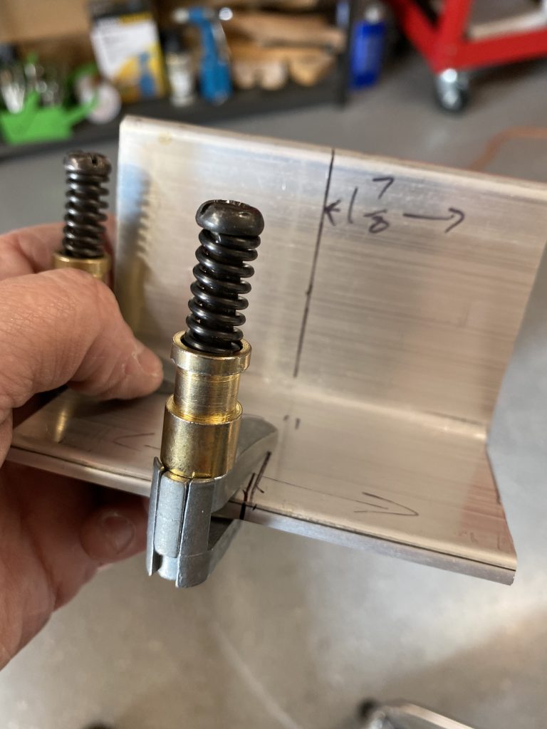
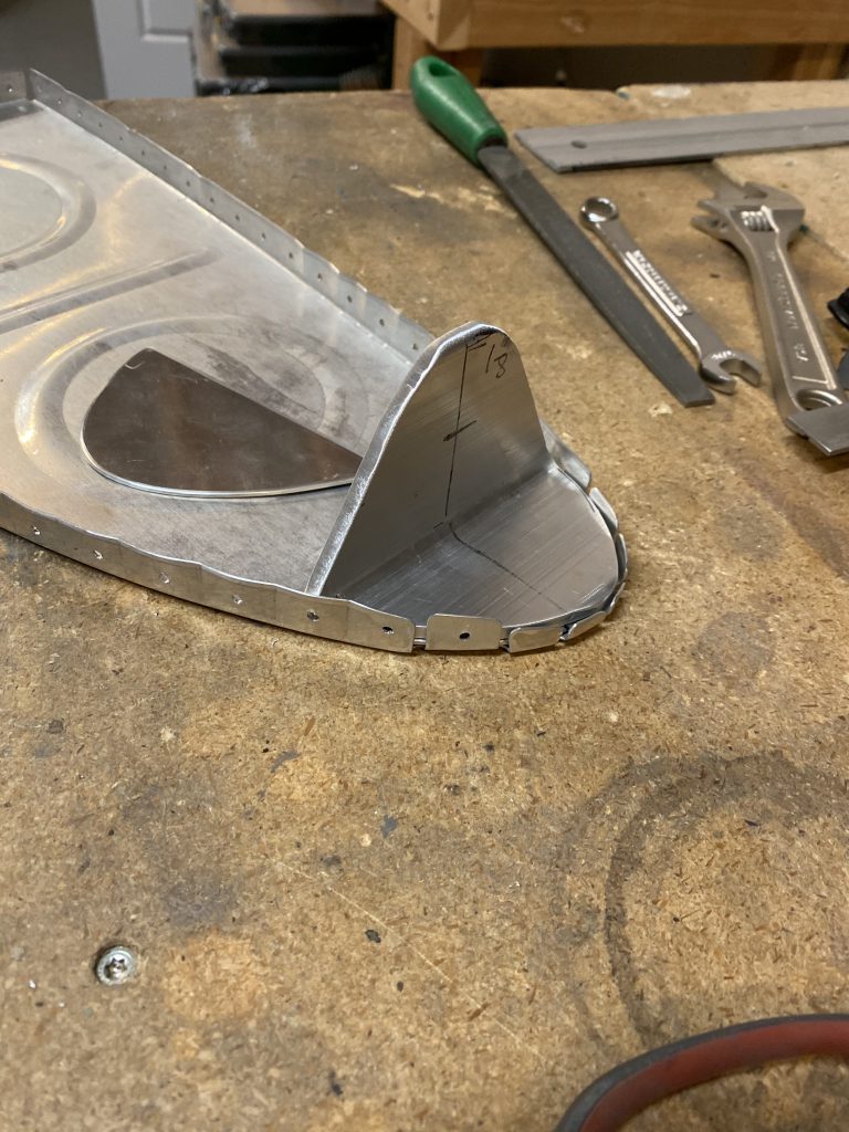
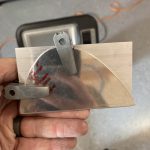
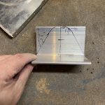
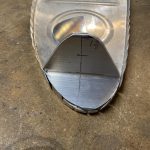
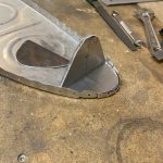
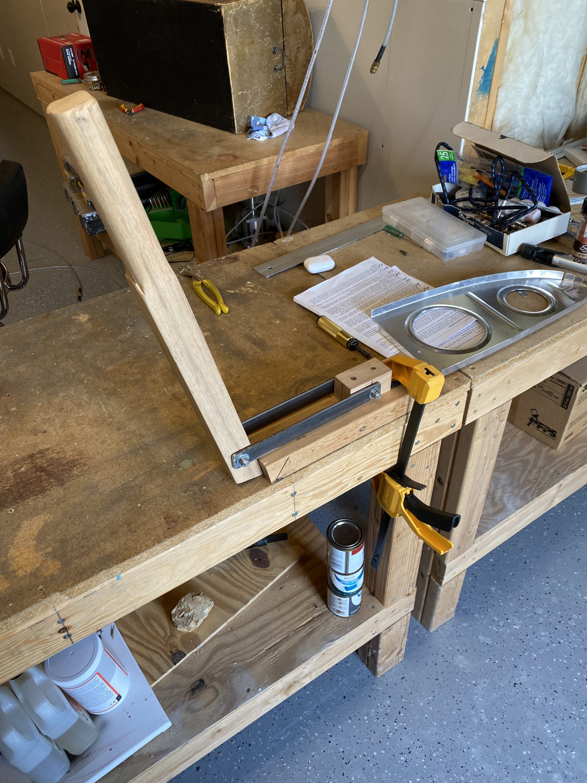
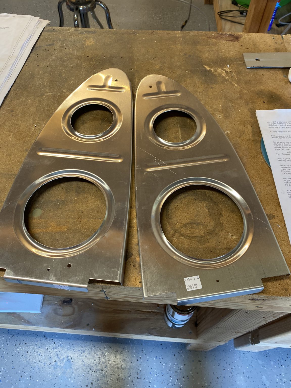
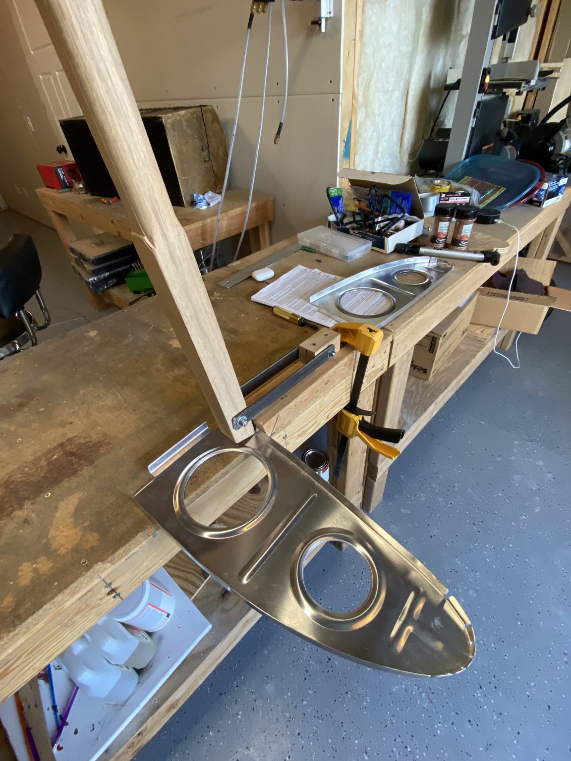
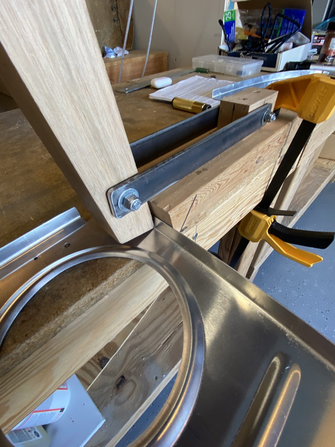
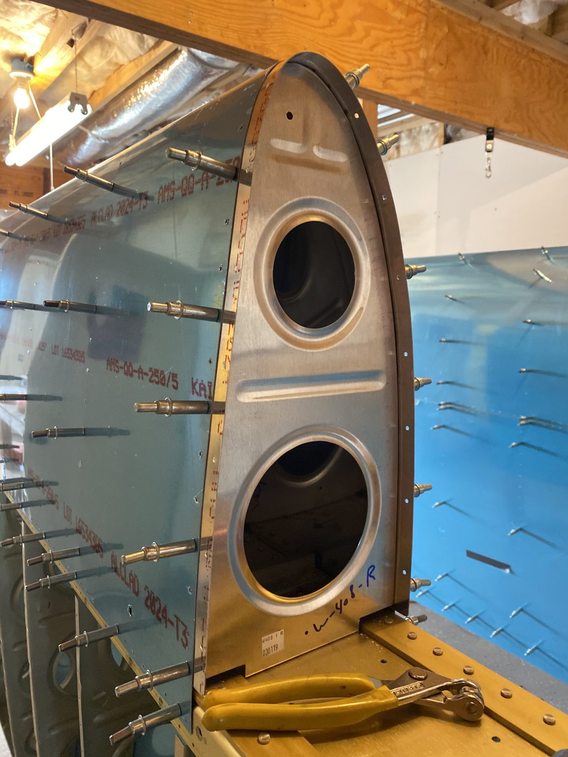
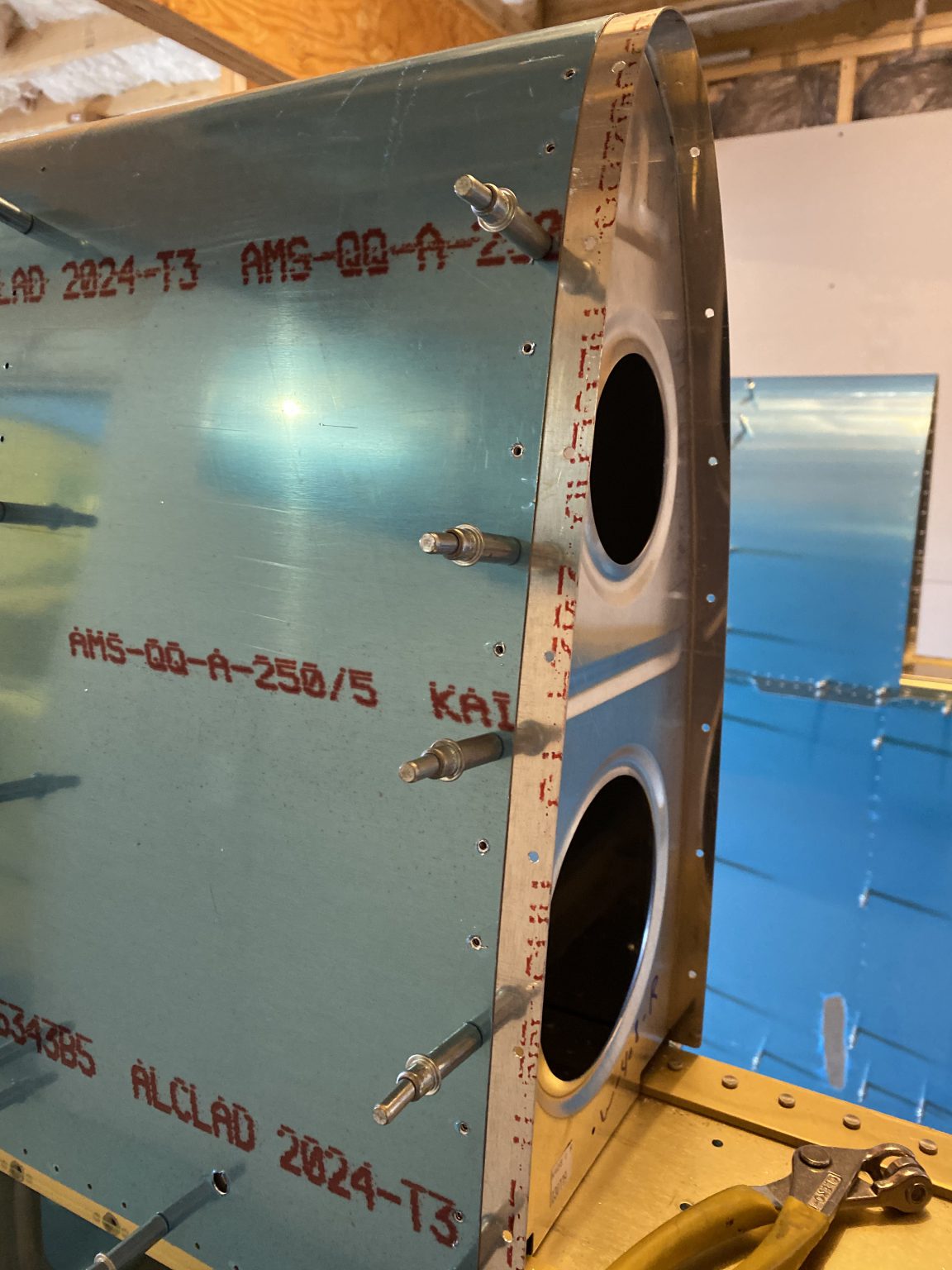
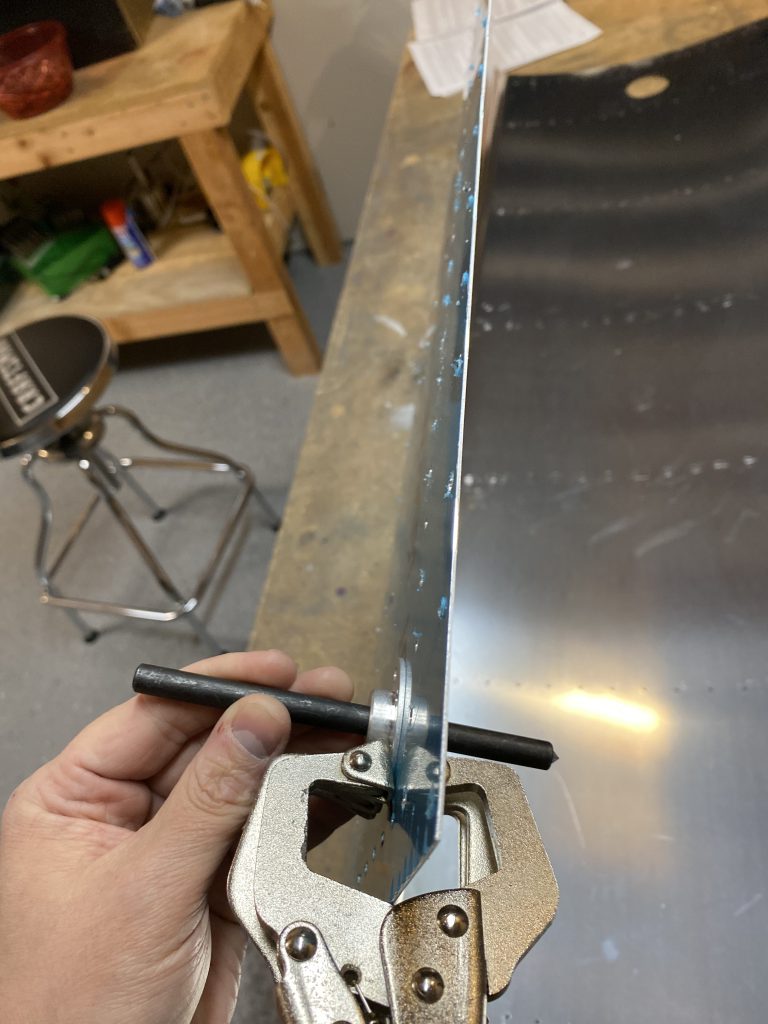
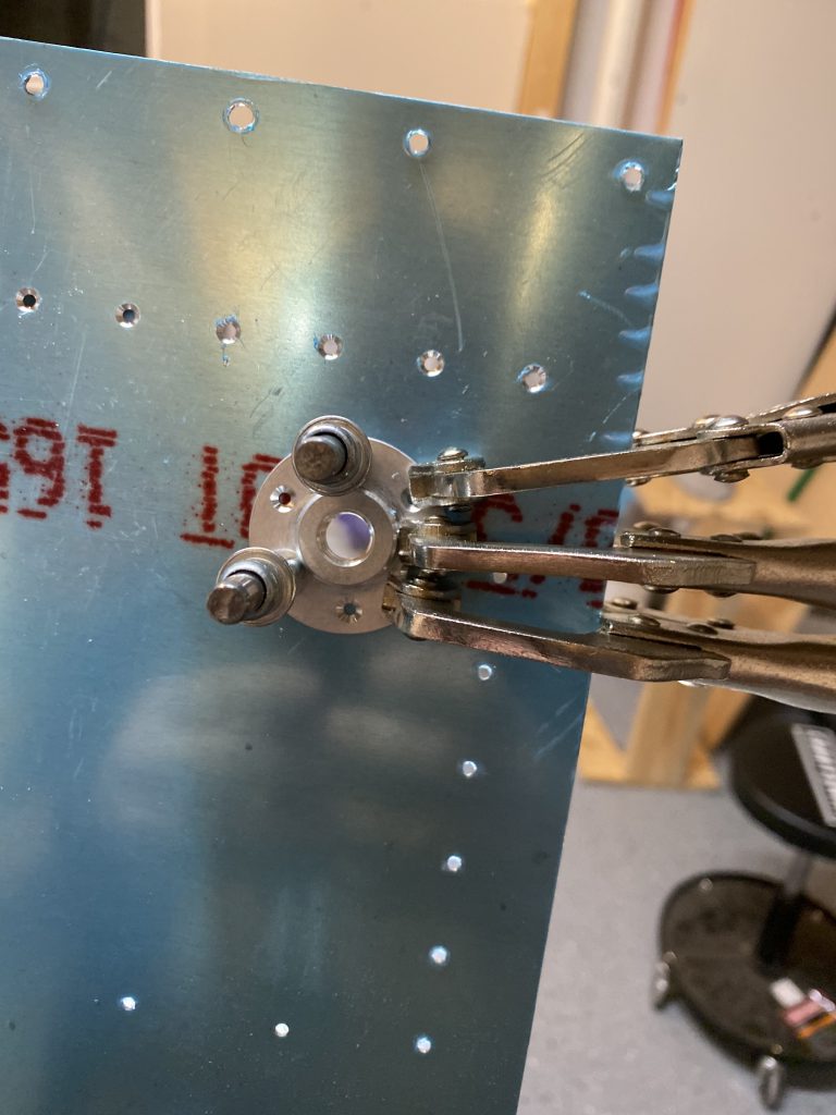
Then I deburred these holes, and placed the bracket into the rib and lined it up and nice and square so that I could use the bracket as a template to back drill the holes in the rib.  I used some clamps to help hold it in place.  Notice that I left off the reinforcement plate that goes on the back side of the T-703-R/L rib. I did that on purpose so it would be easier to line up.

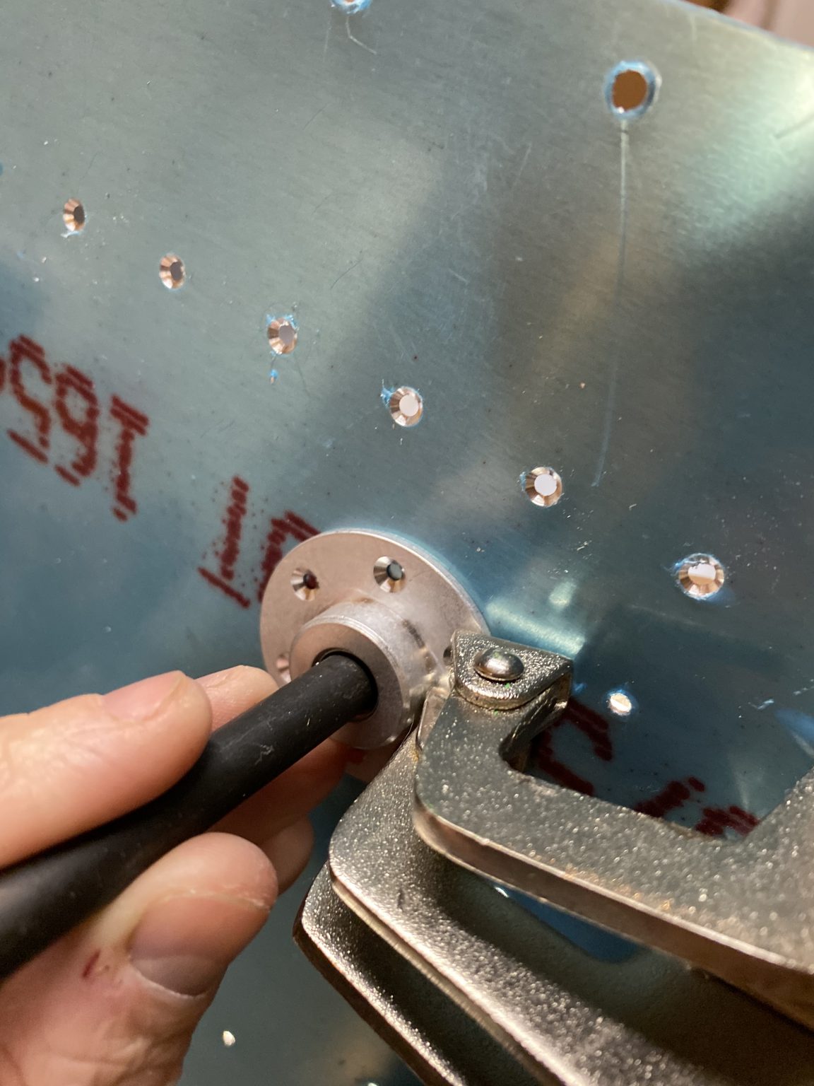
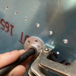
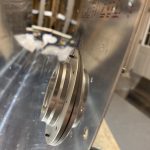
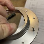
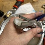
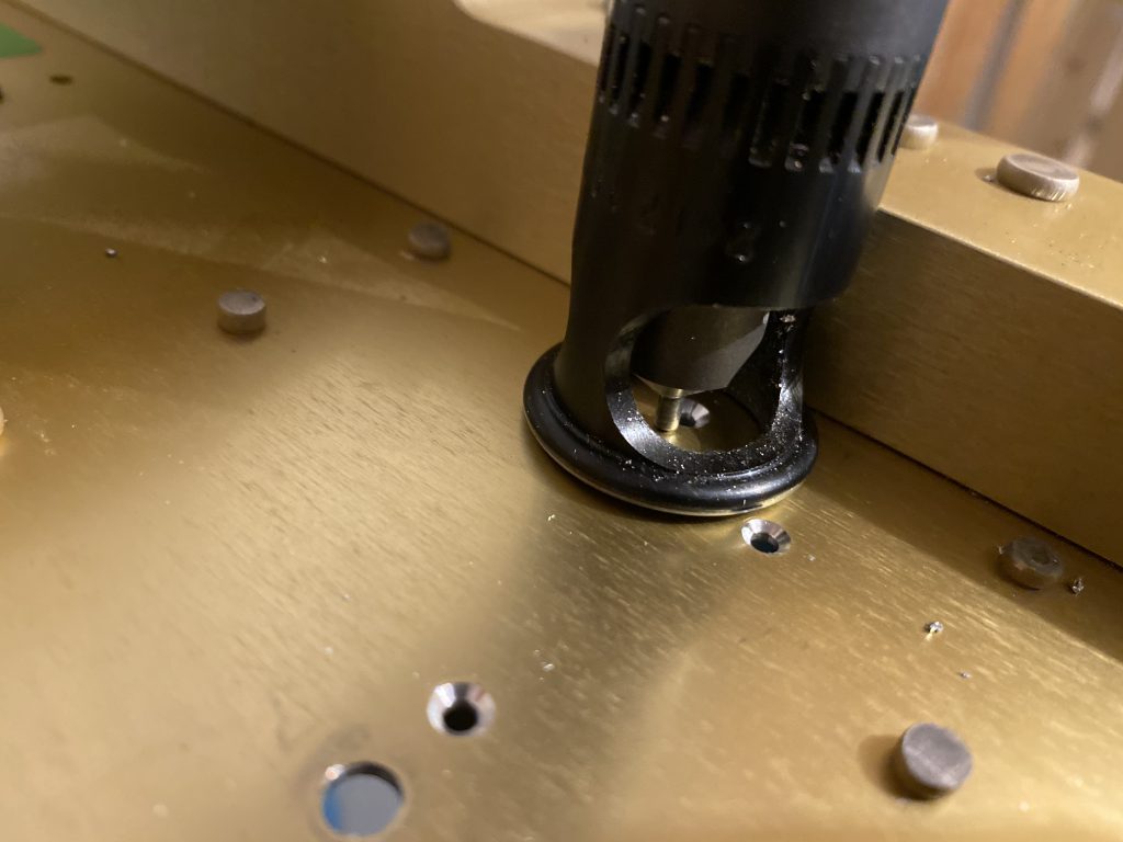
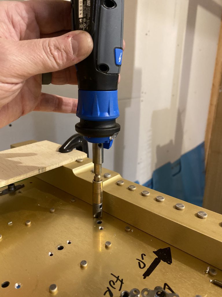
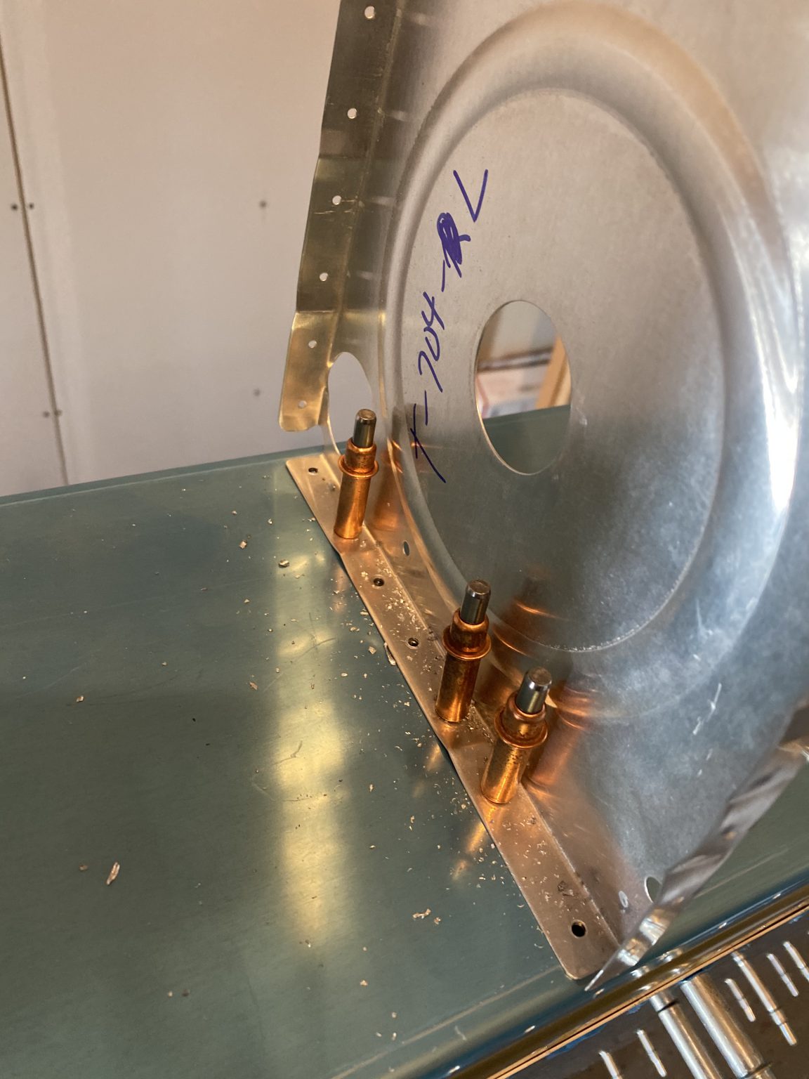
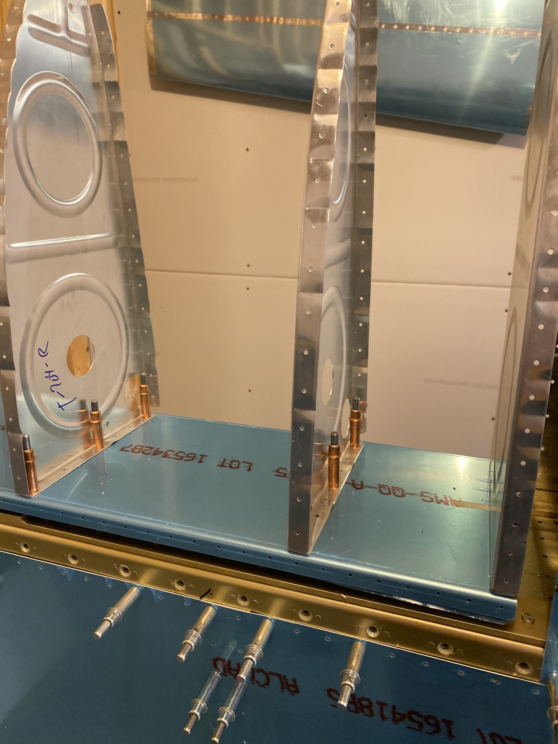
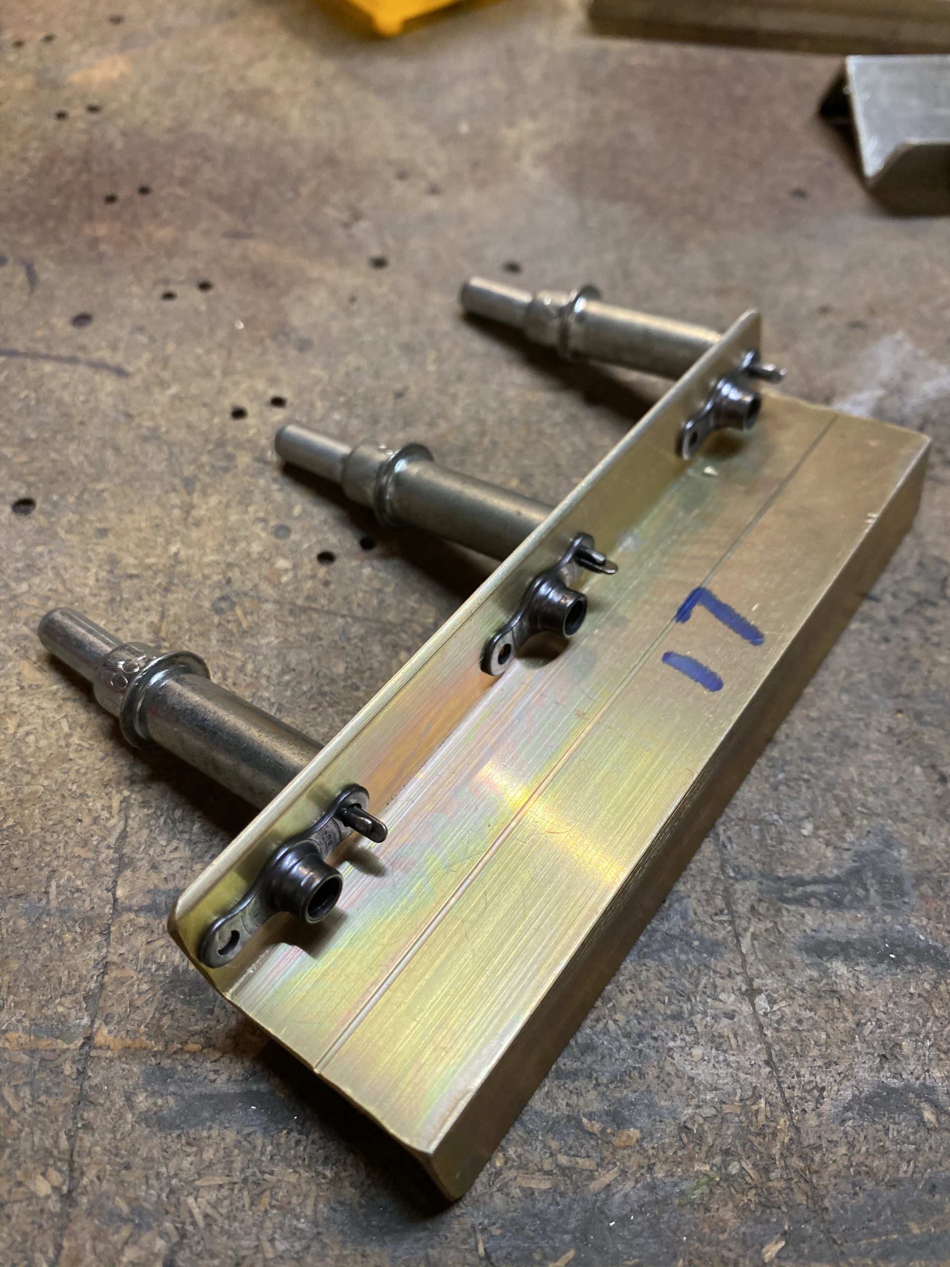
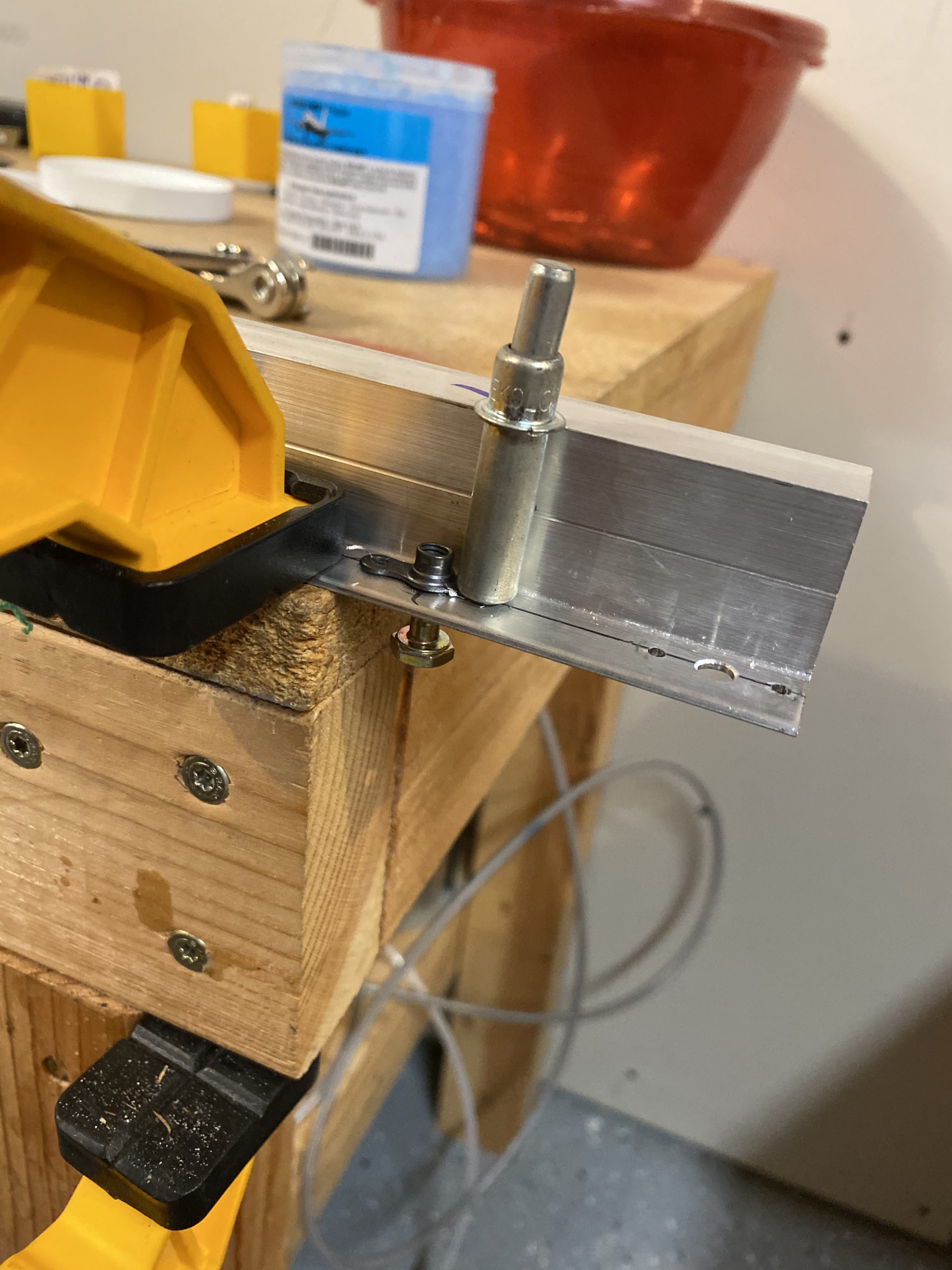
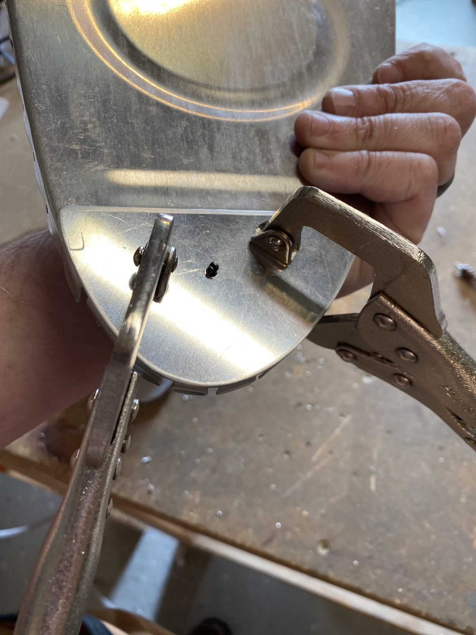
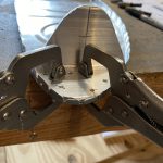
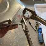
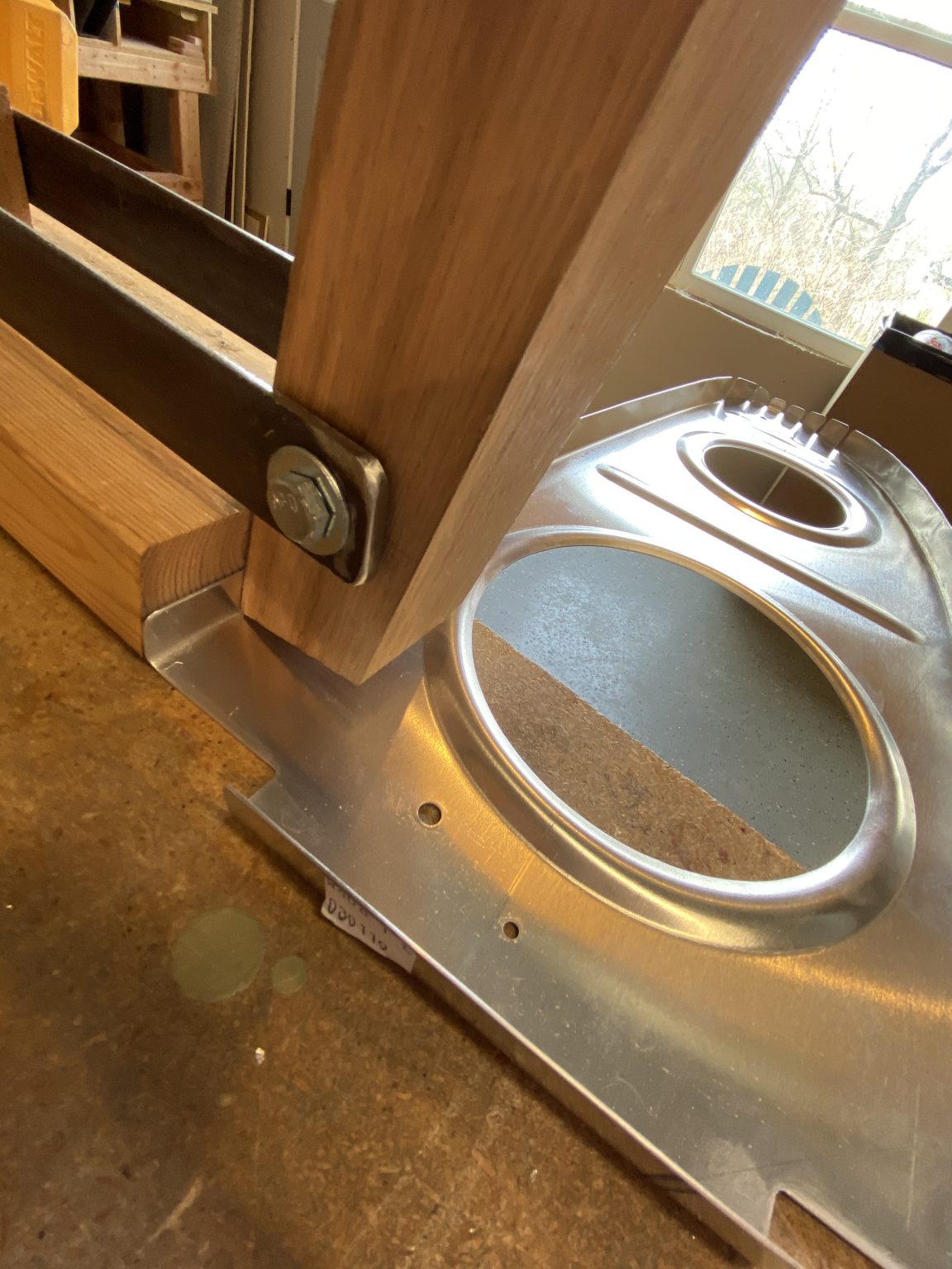
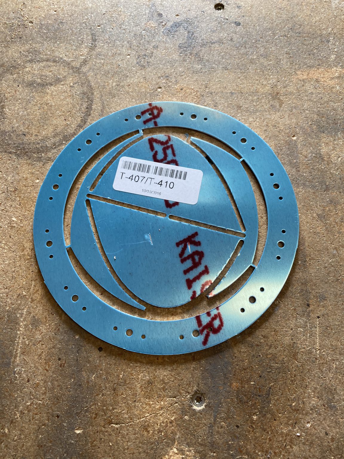
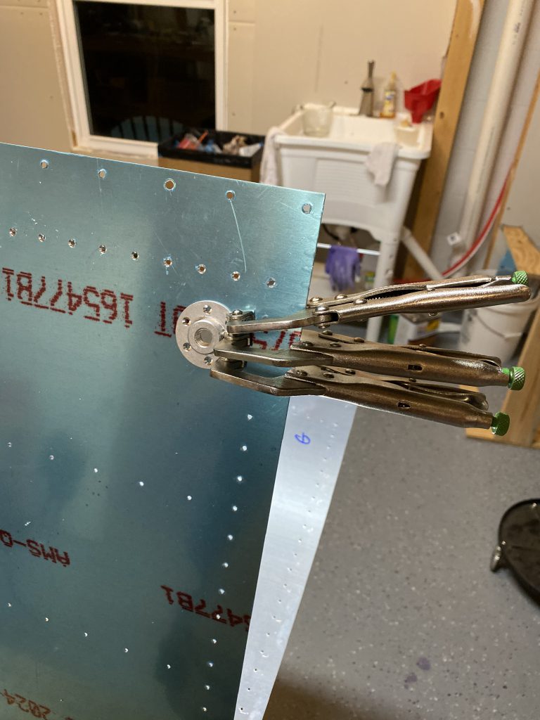
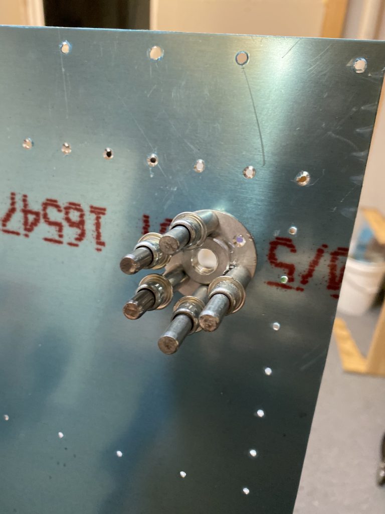
With the bracket lined up and clamped, I simple back drilled into the tank rib using the bracket as my template.  Once I had the rib drilled, I removed the bracket and then placed the T-410 reinforcement plate on the inside of the tank rib, and lined it up.  Once it was lined up where I wanted it, I clamped it down and used the newly drilled holes in the T-703-R/L tank ribs to back drill into the T-410.

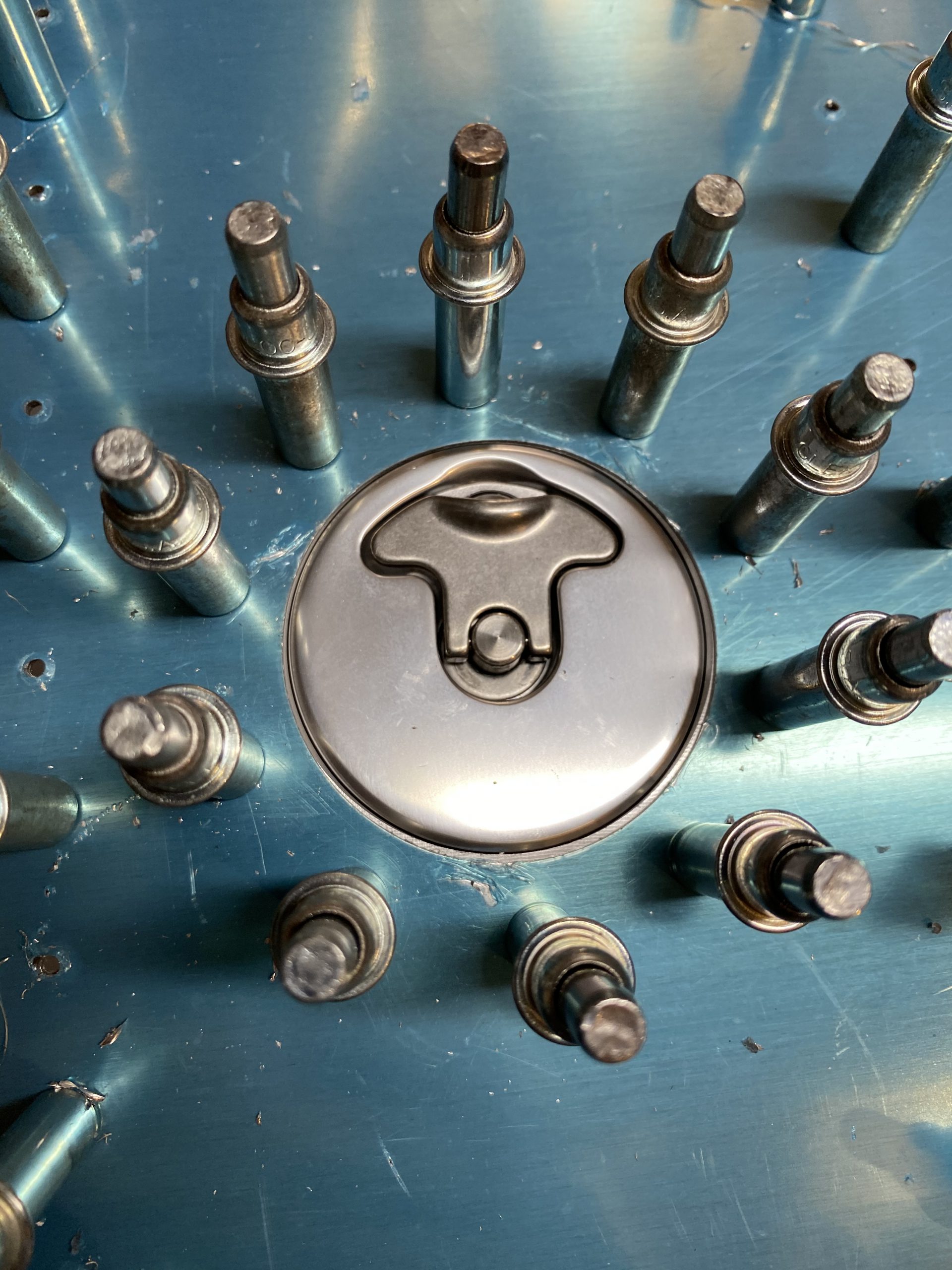
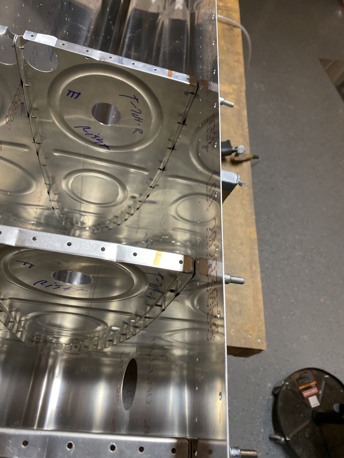
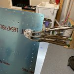
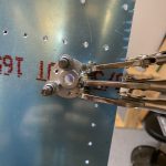
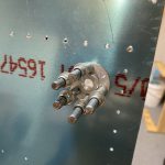
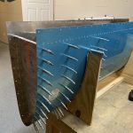
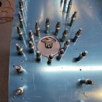
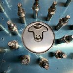
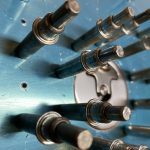
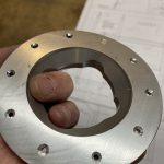
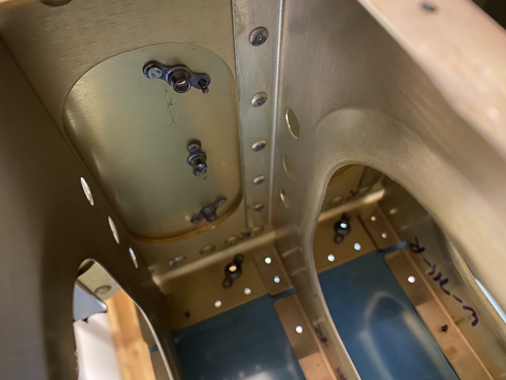
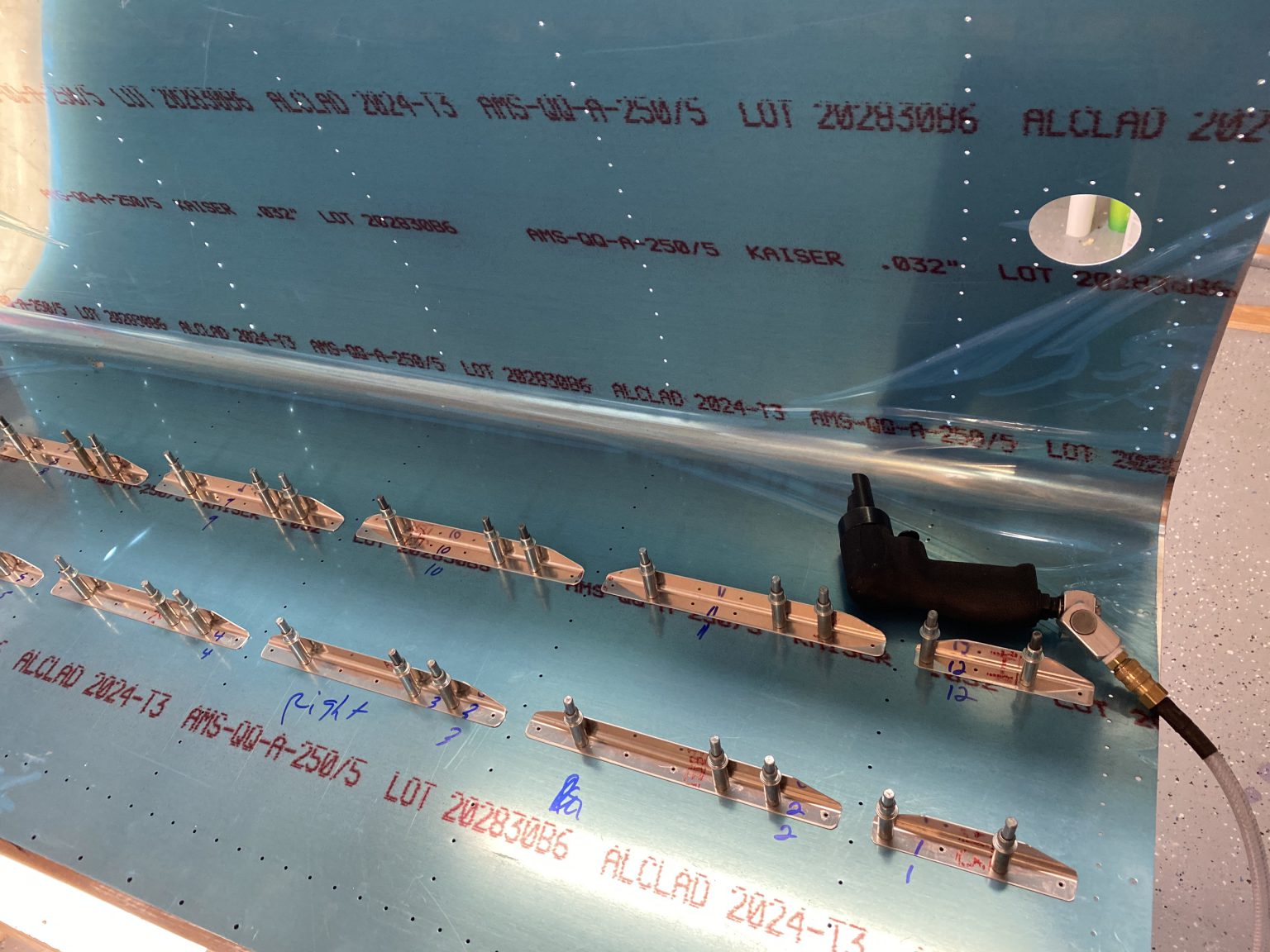
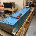
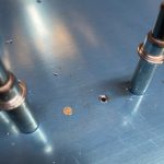
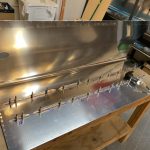
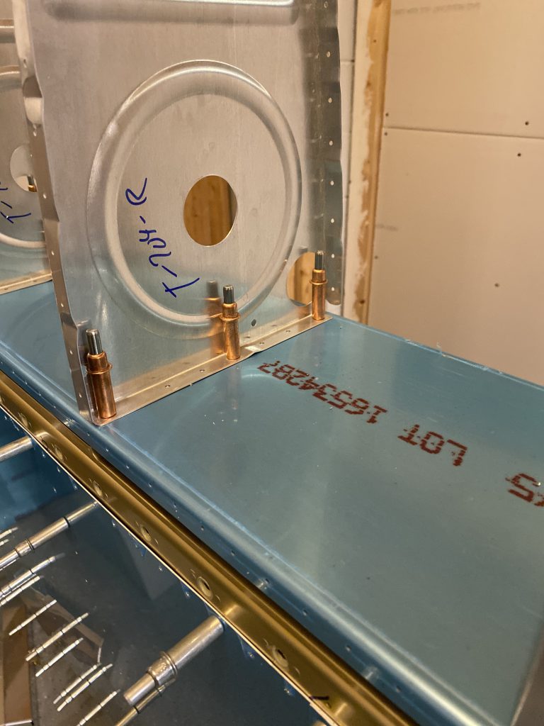
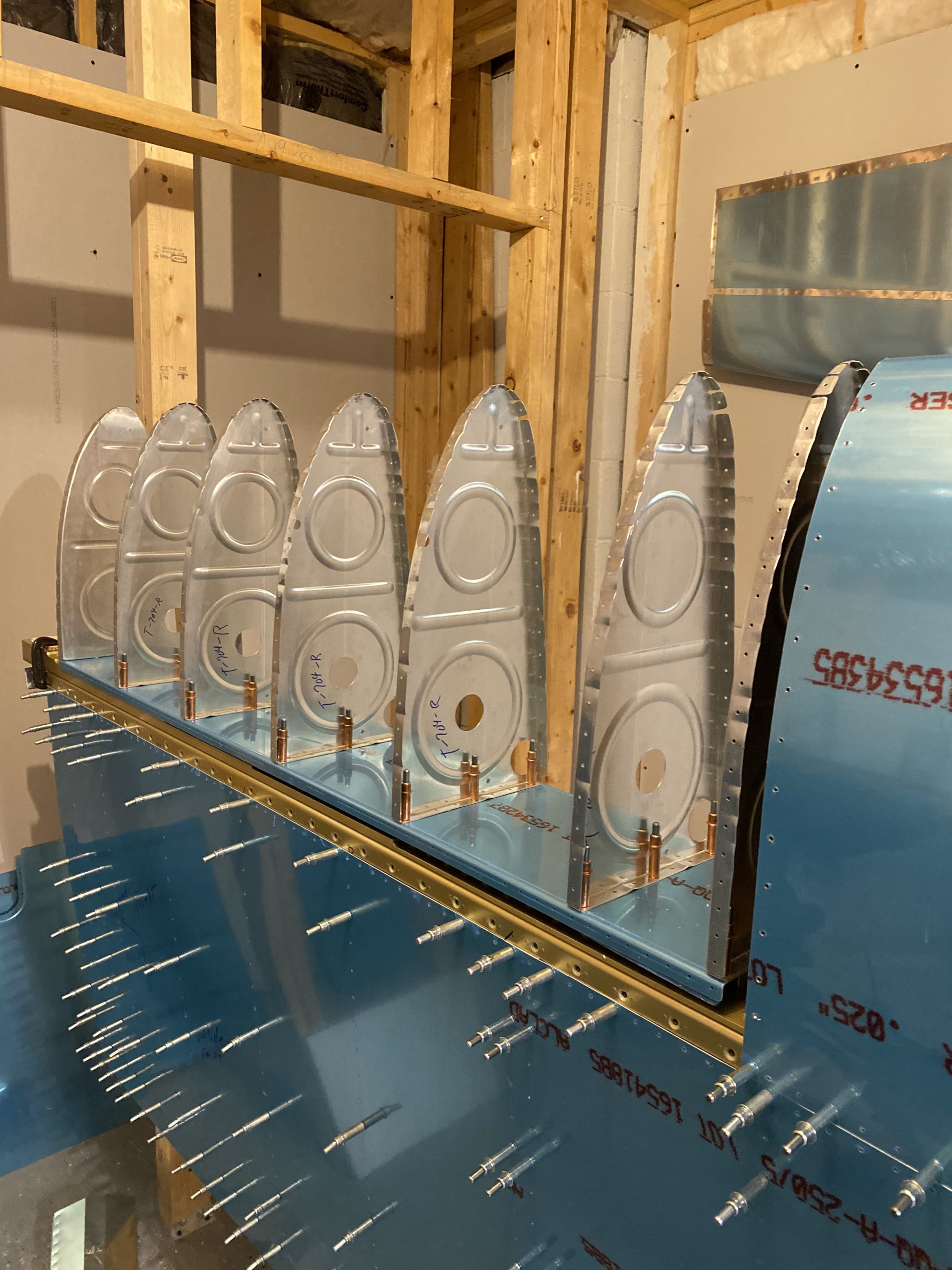
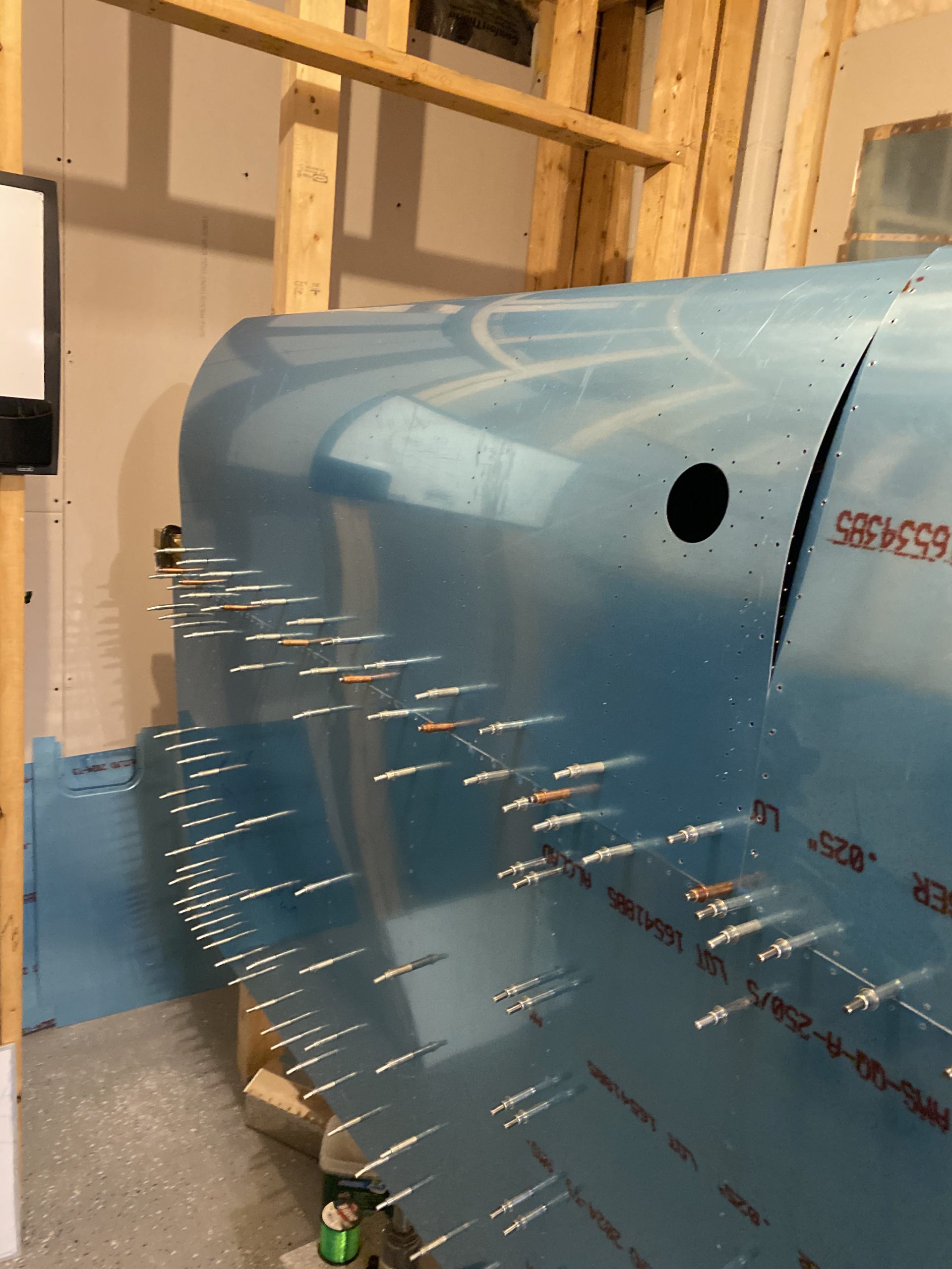
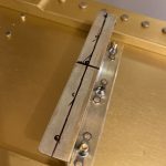
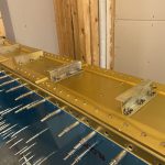
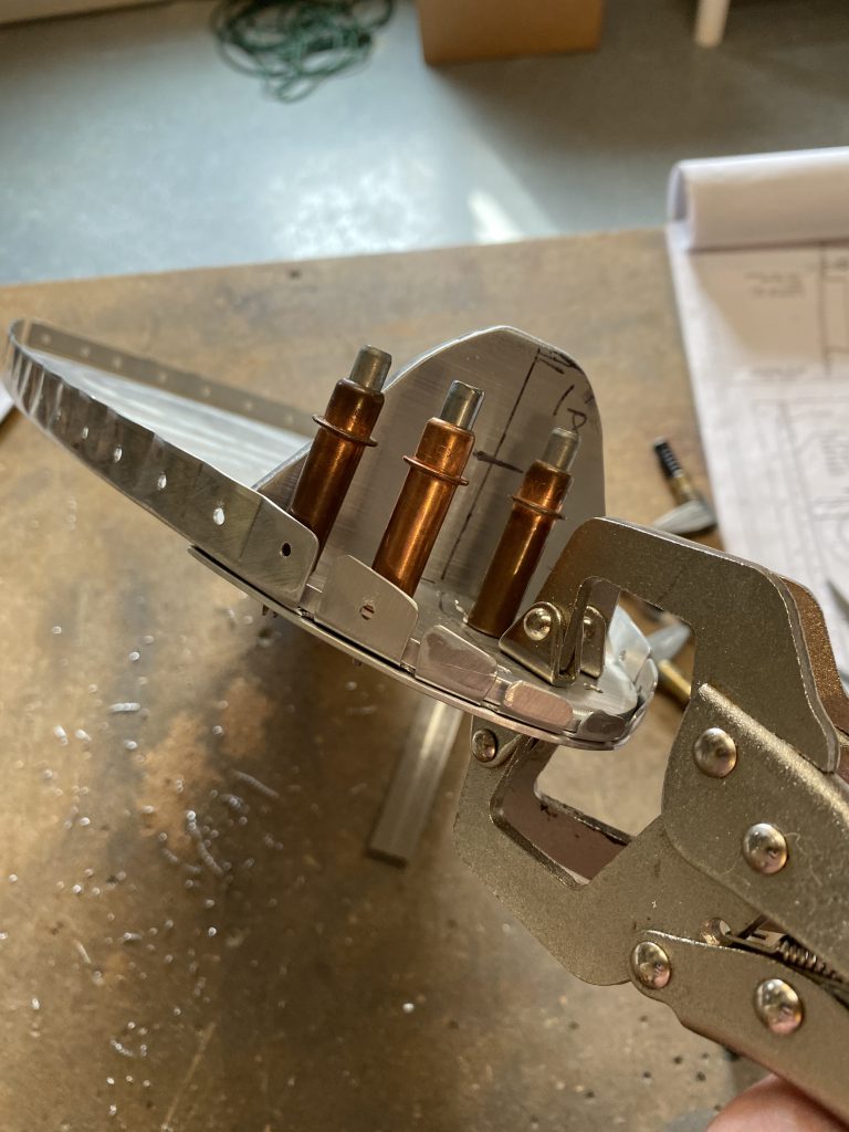
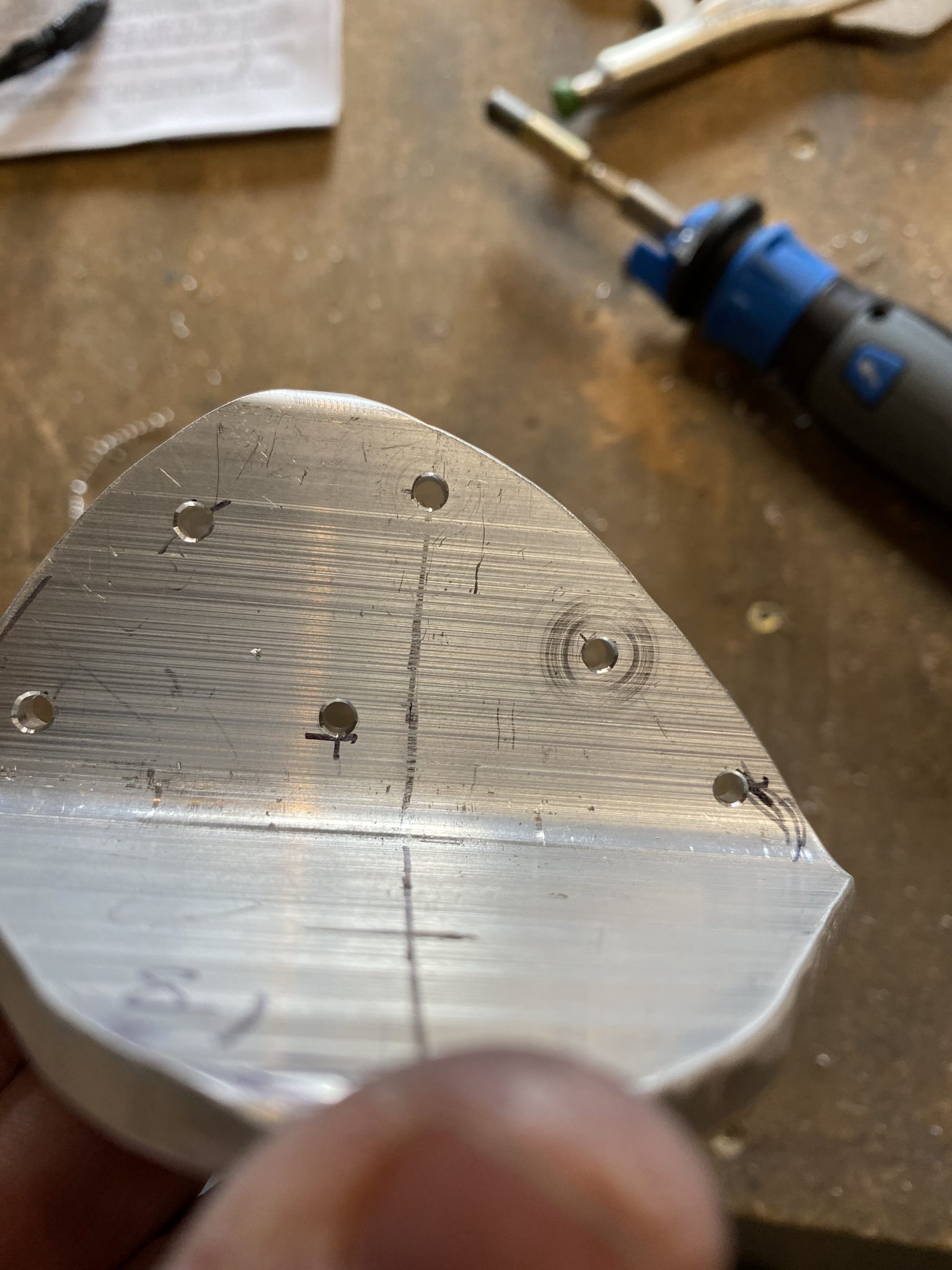
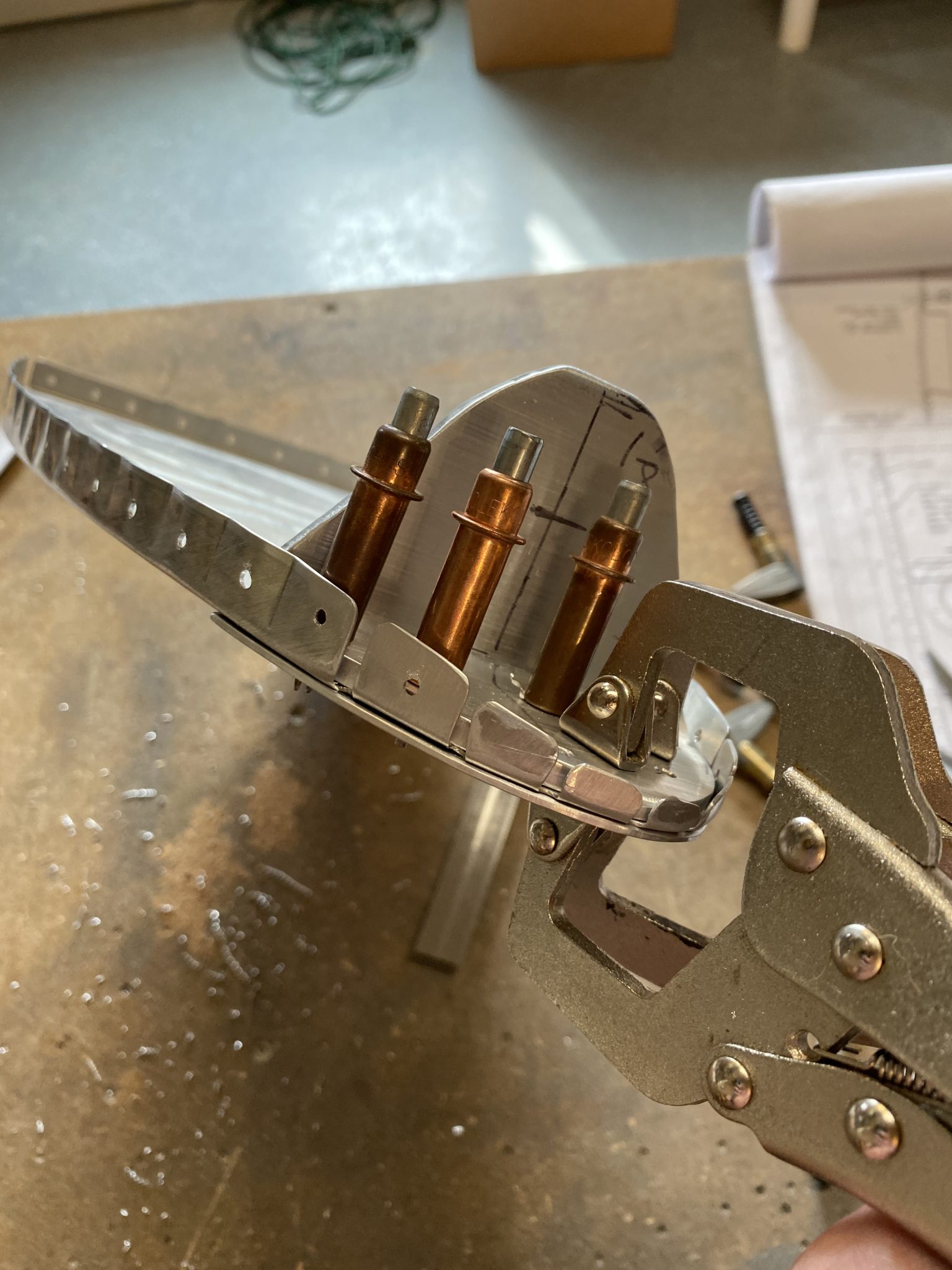
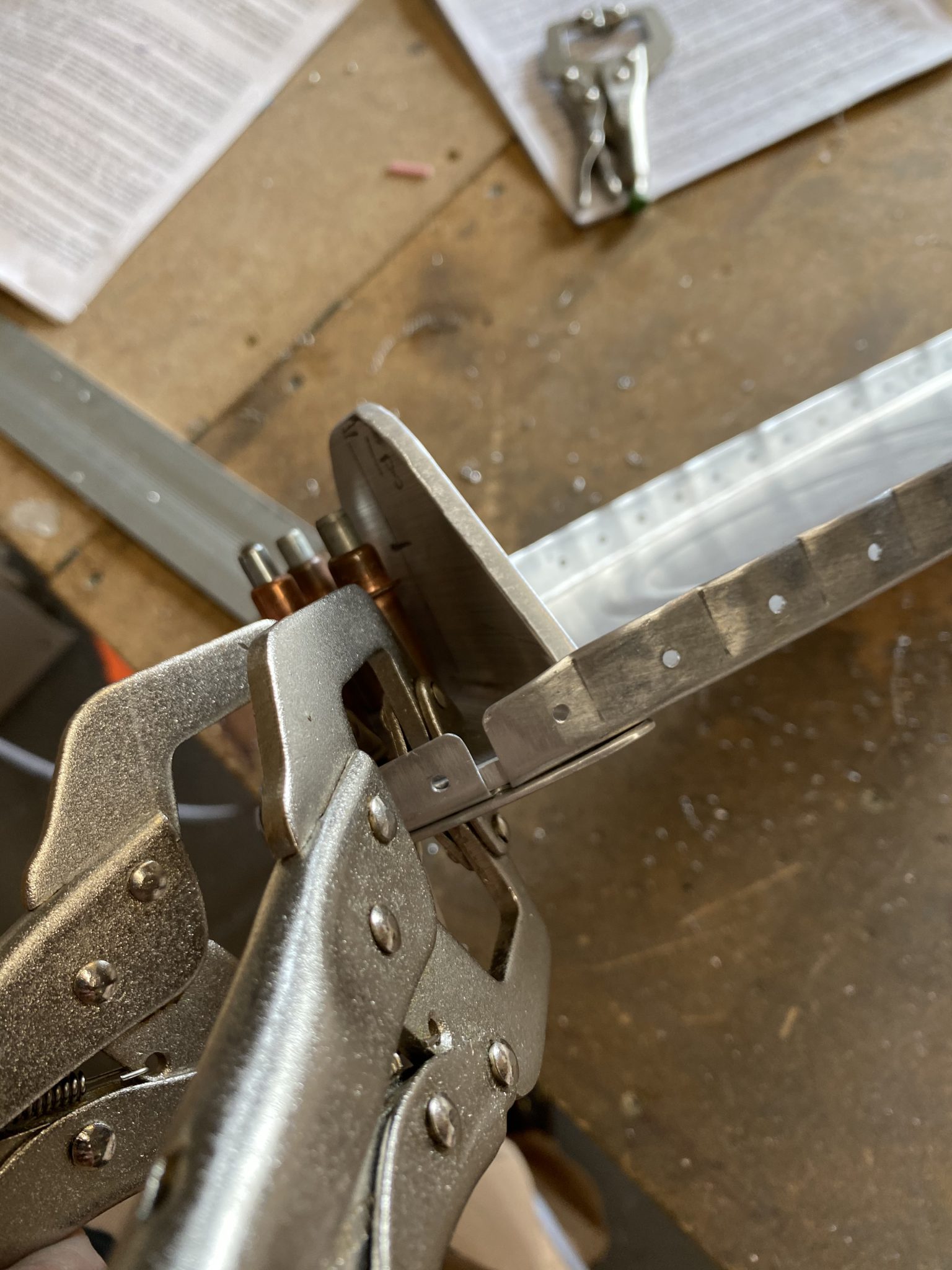
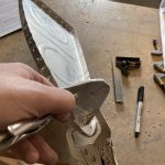
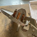
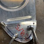
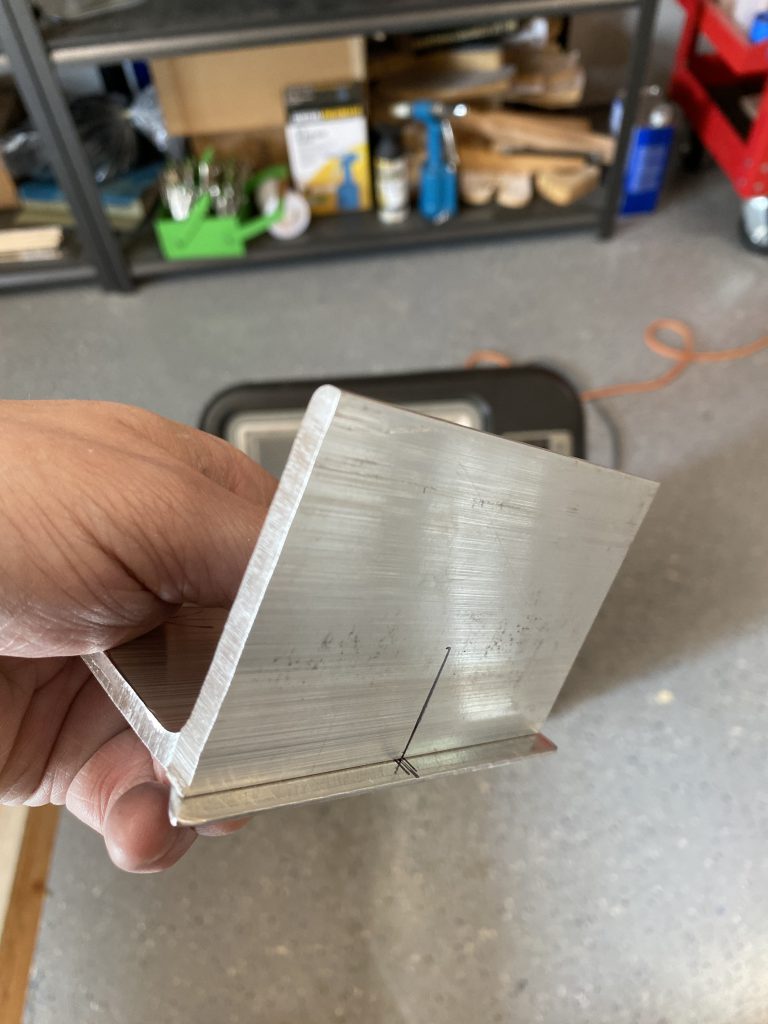
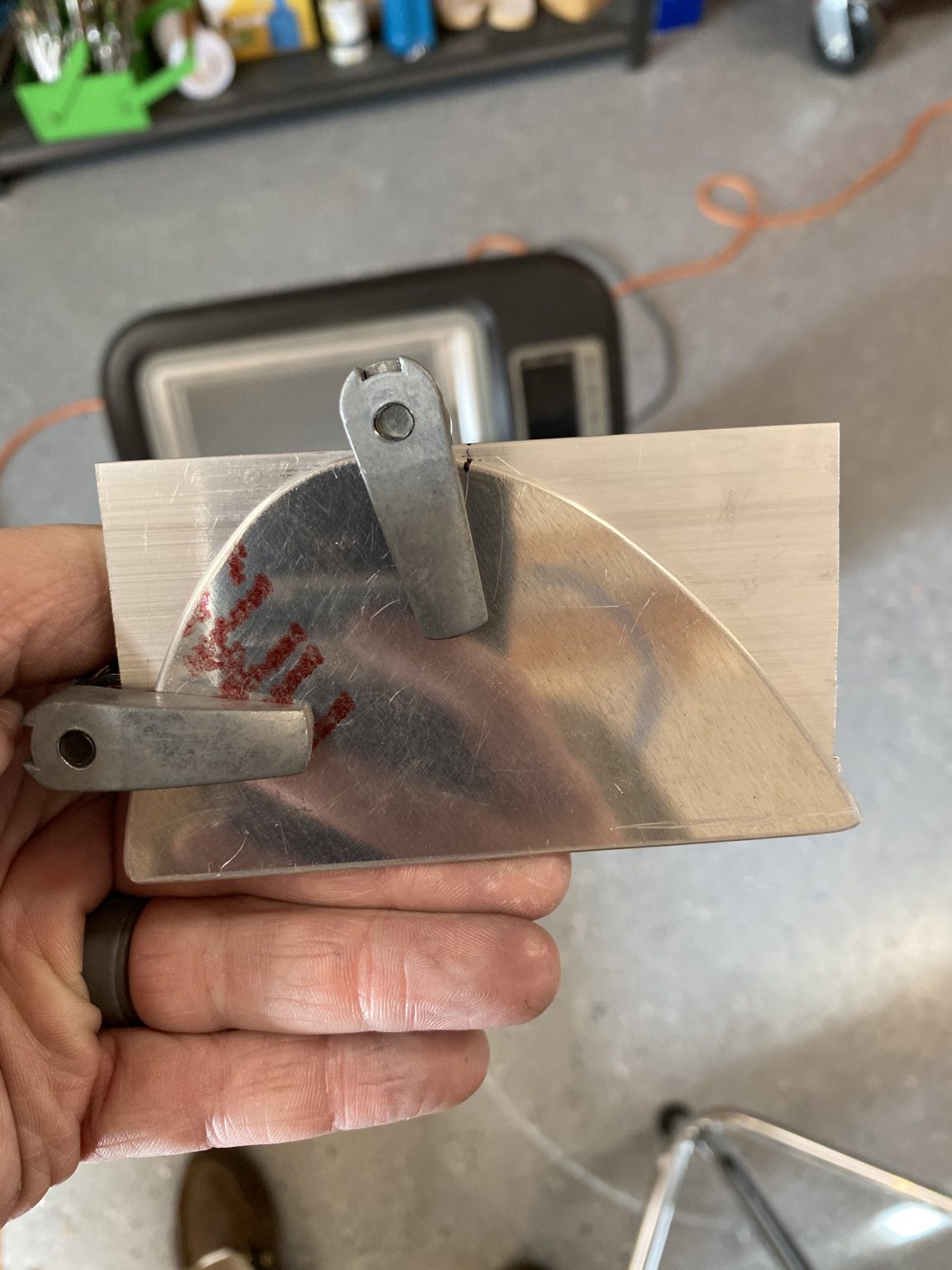
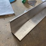
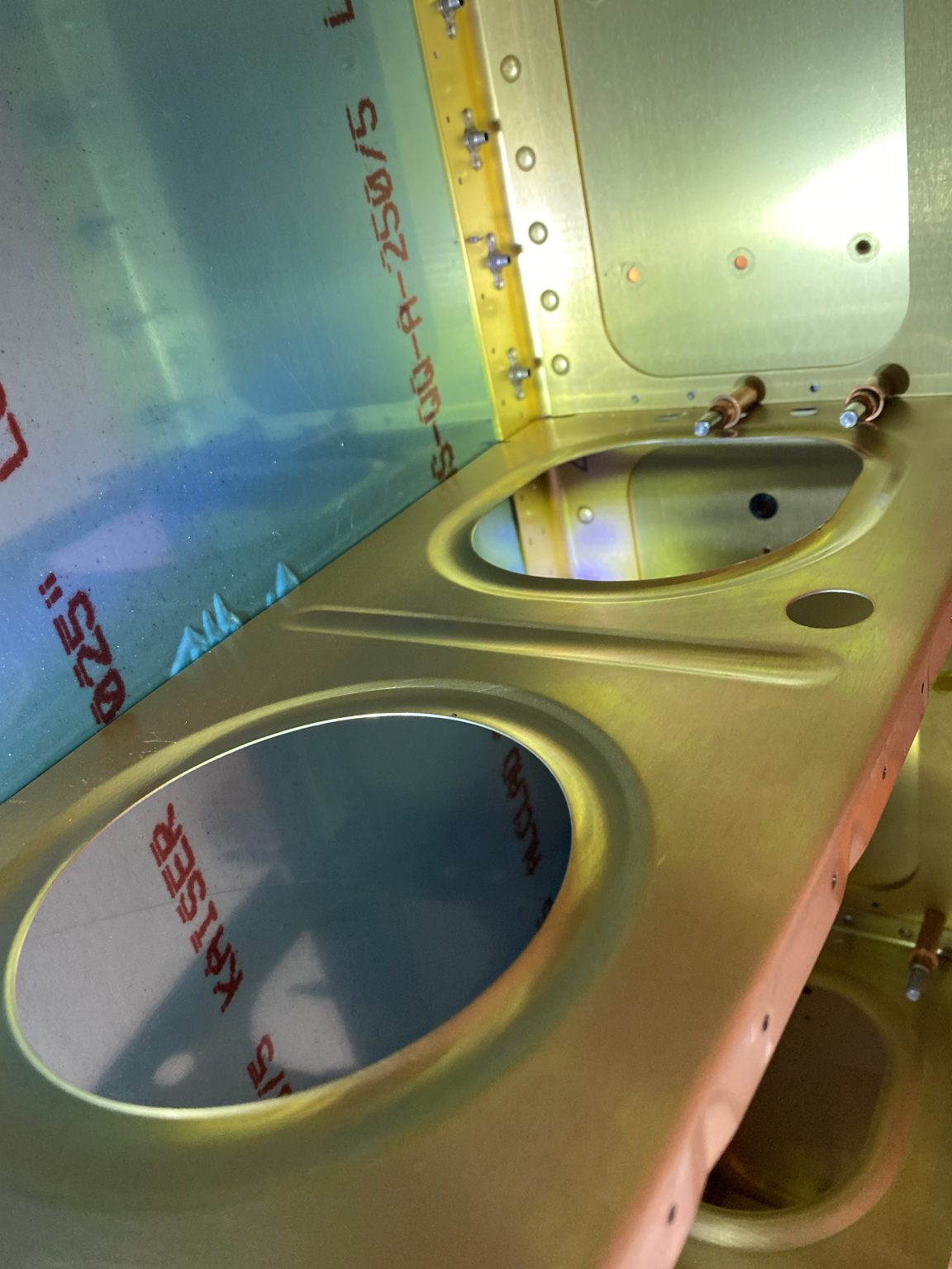
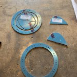
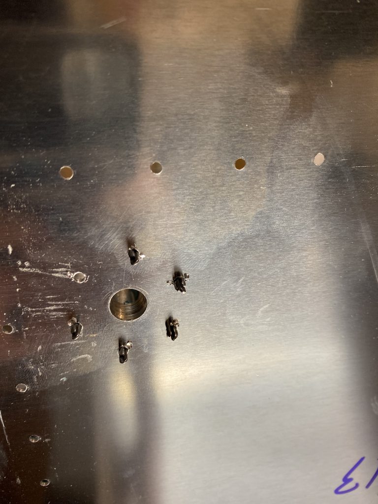
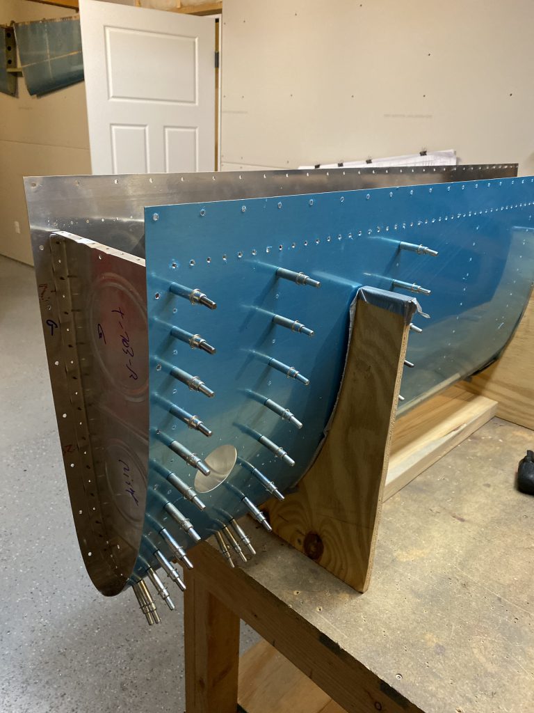
Now that all three parts were drilled, I clecoed everything together to make sure it all fit, and then double checked alignment.  It looked pretty good, so the last thing to do was to deburr all thees new holes and then move on to the outboard rib.

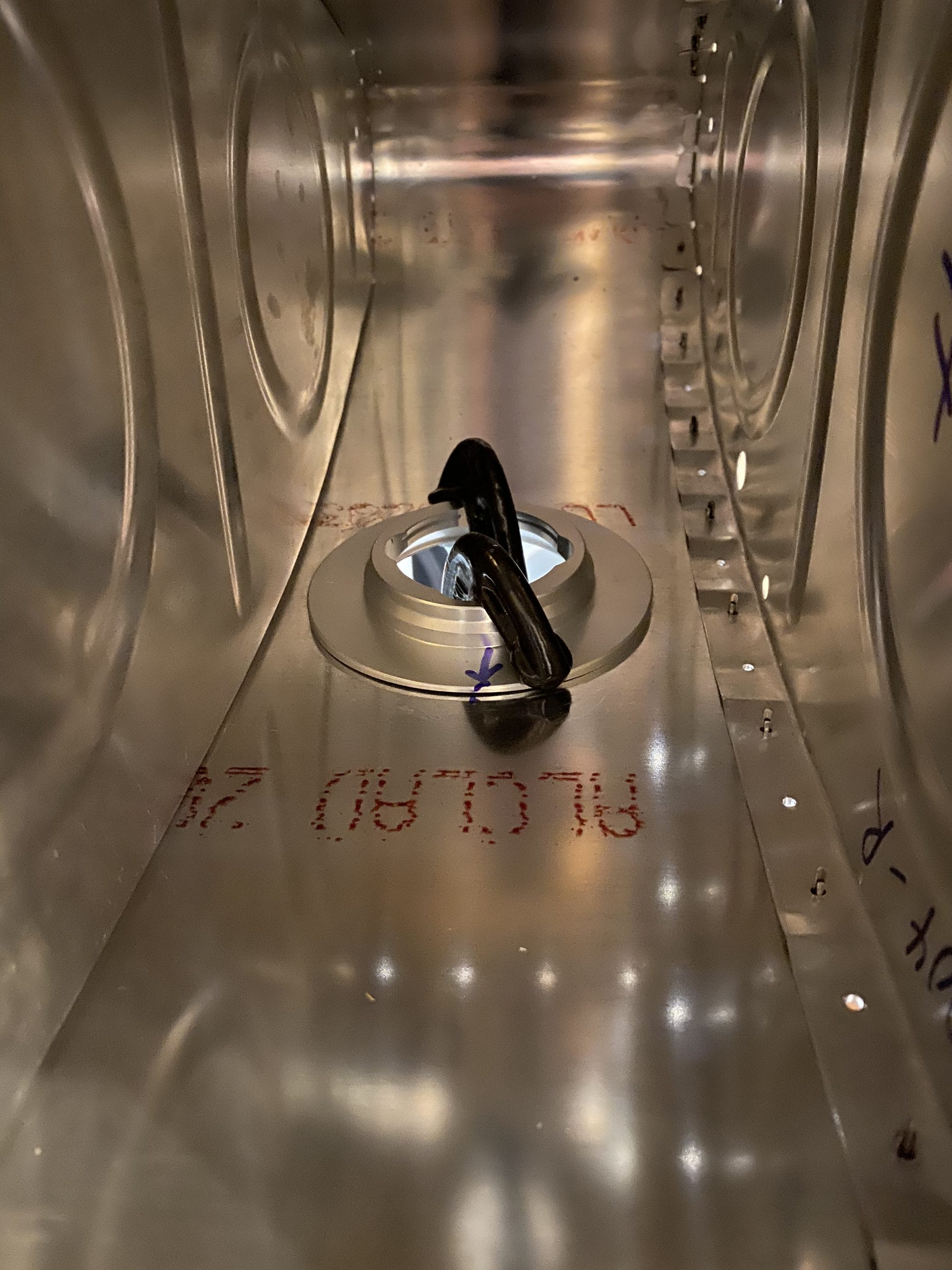
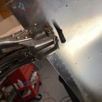
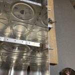
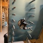
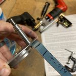
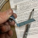
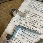
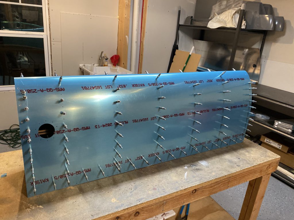
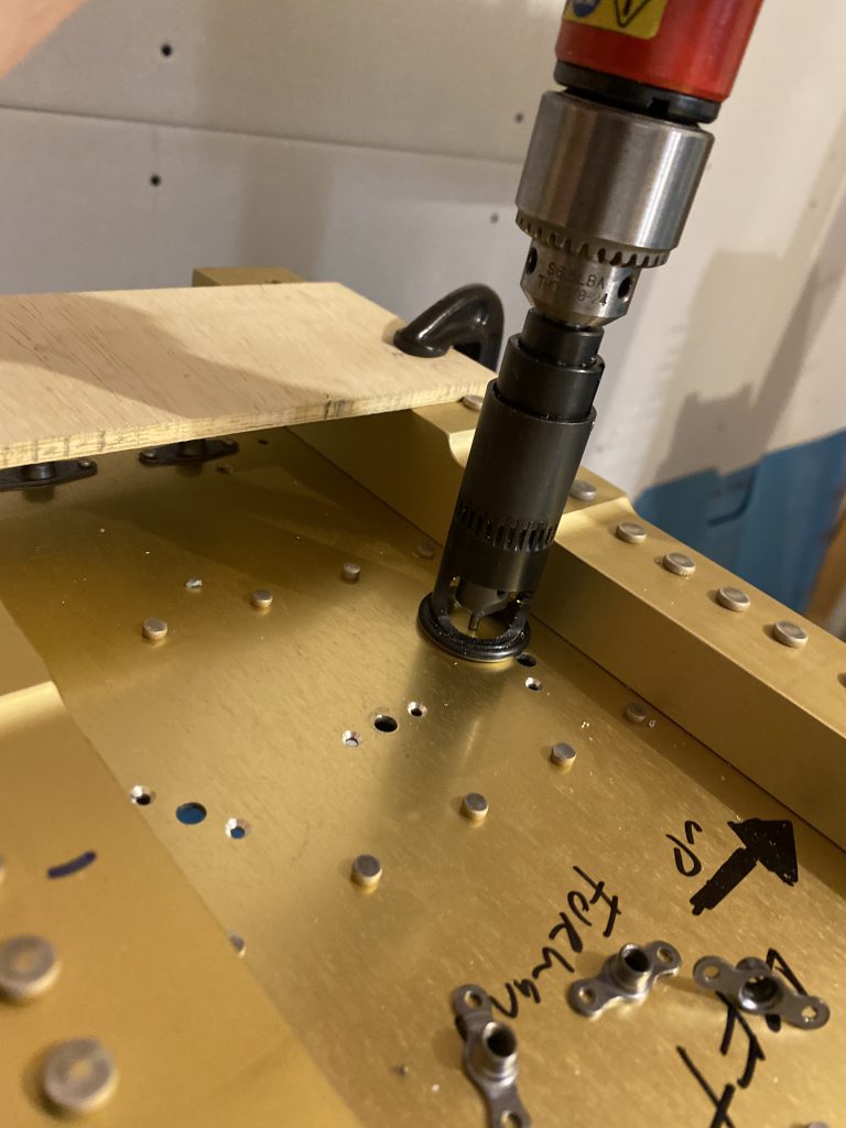
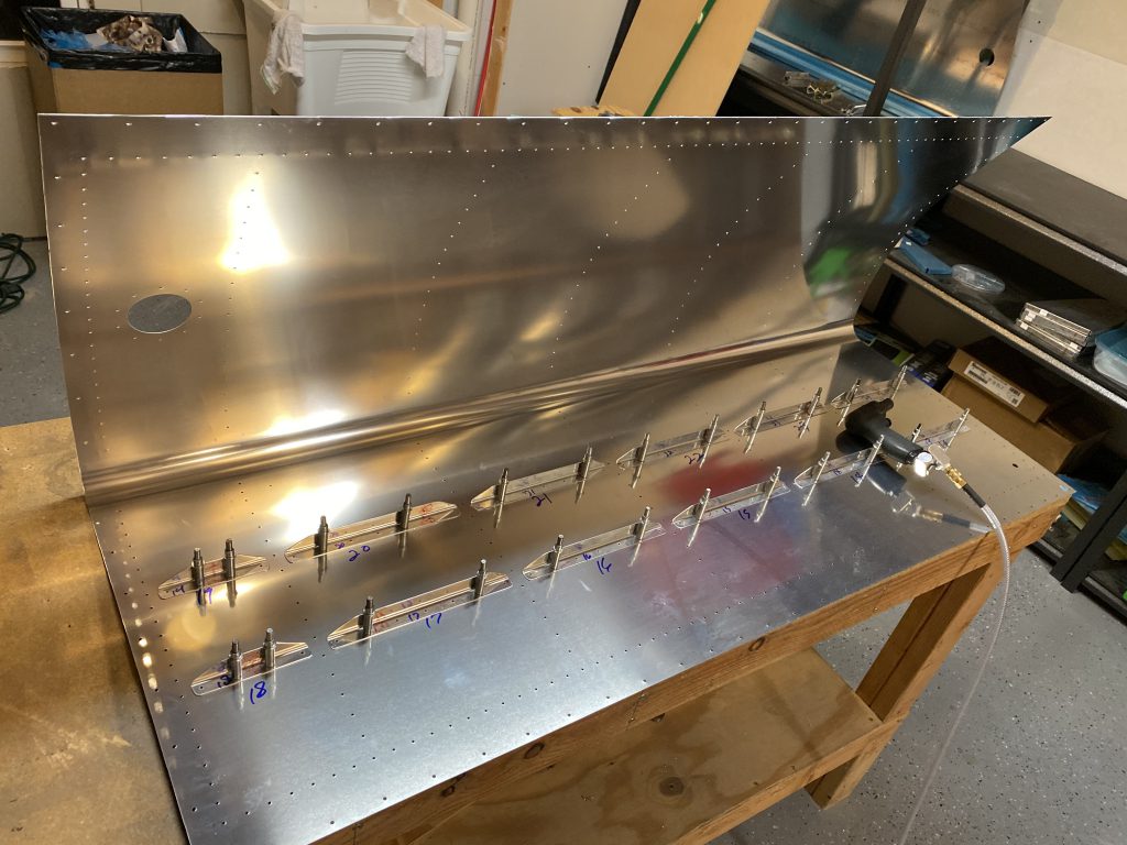
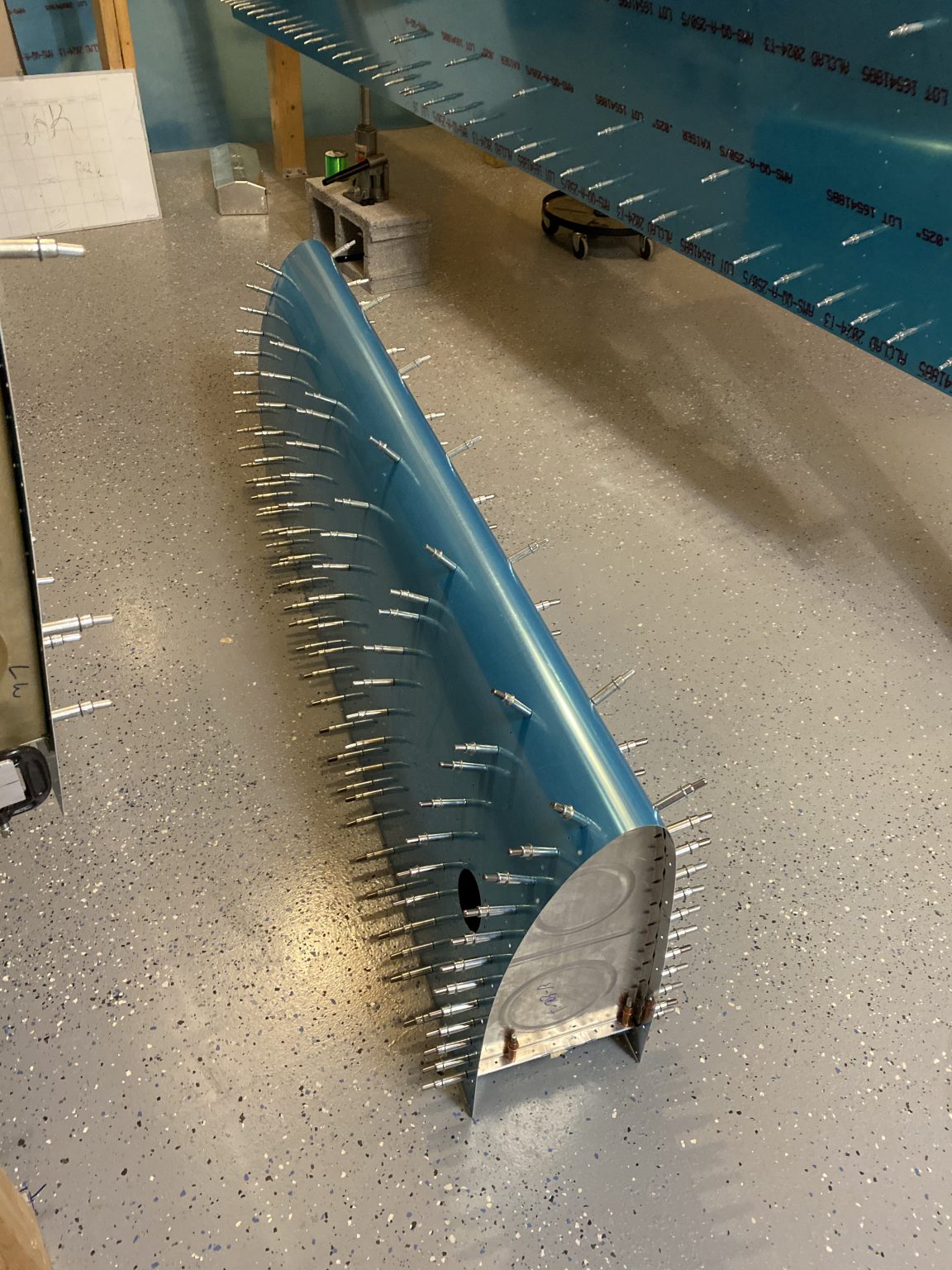
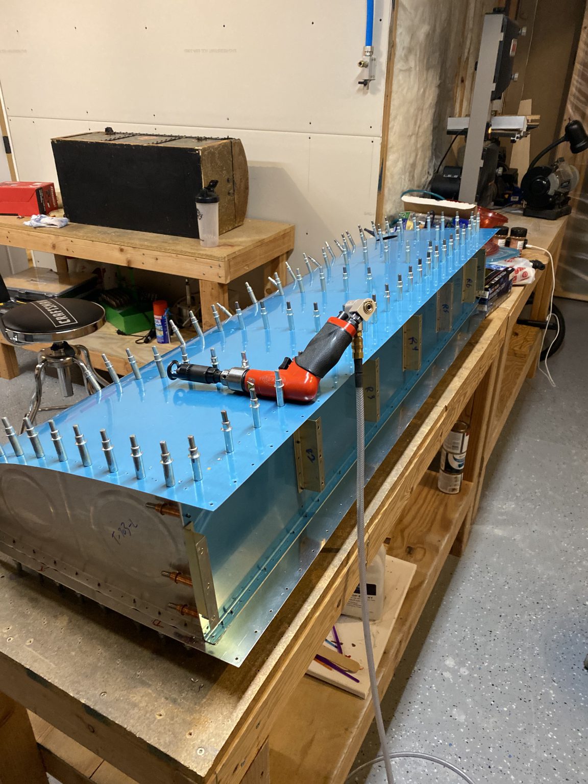
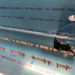
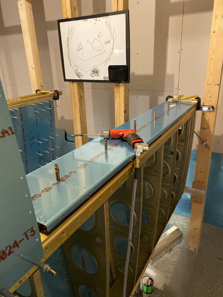
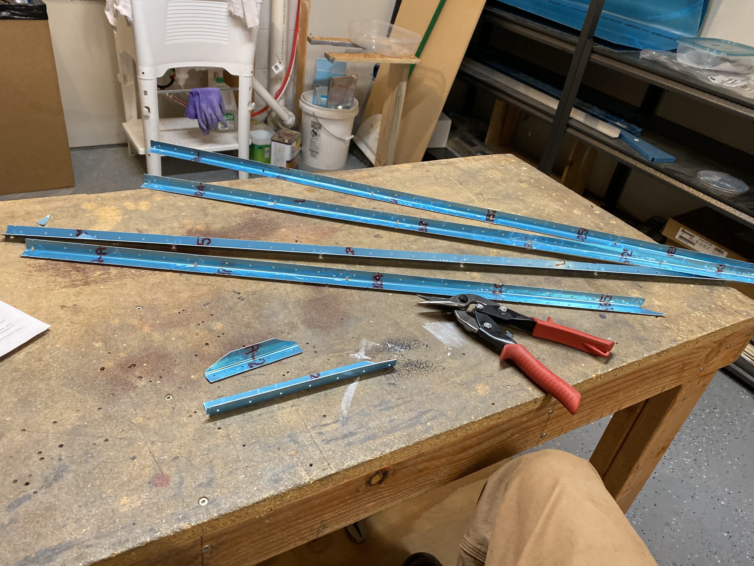
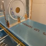
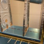
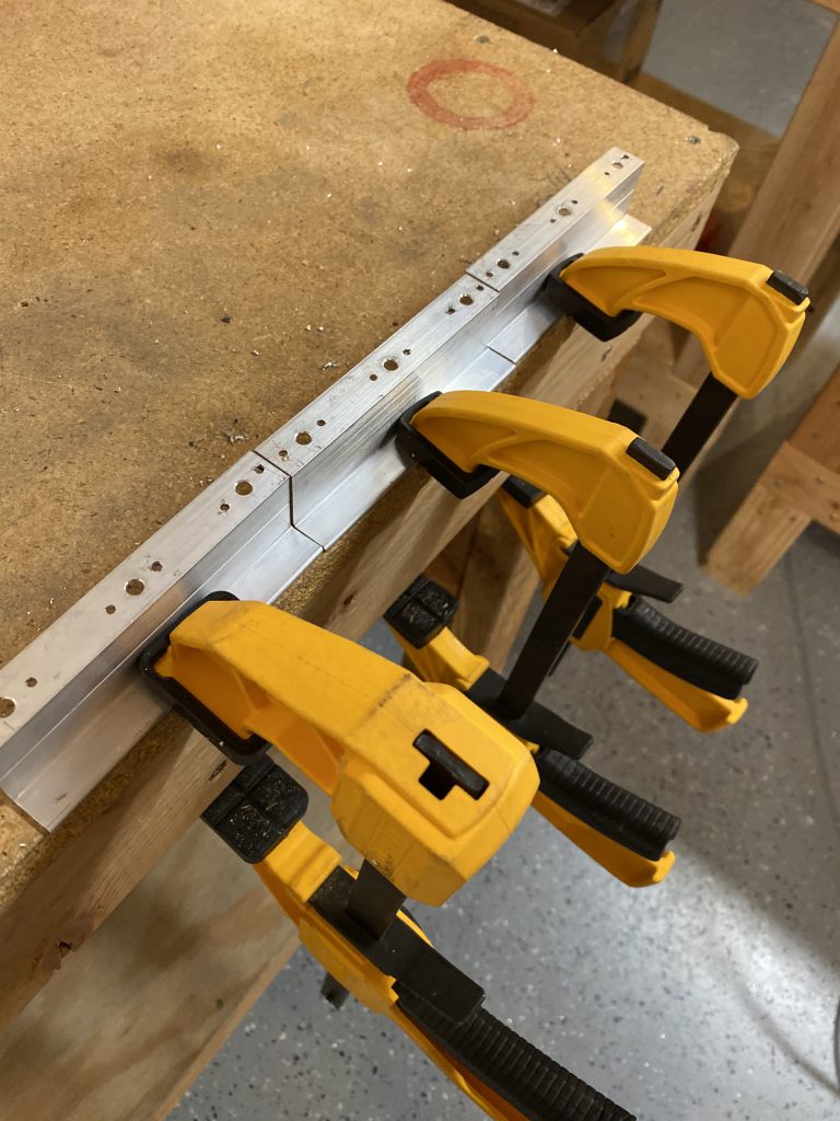
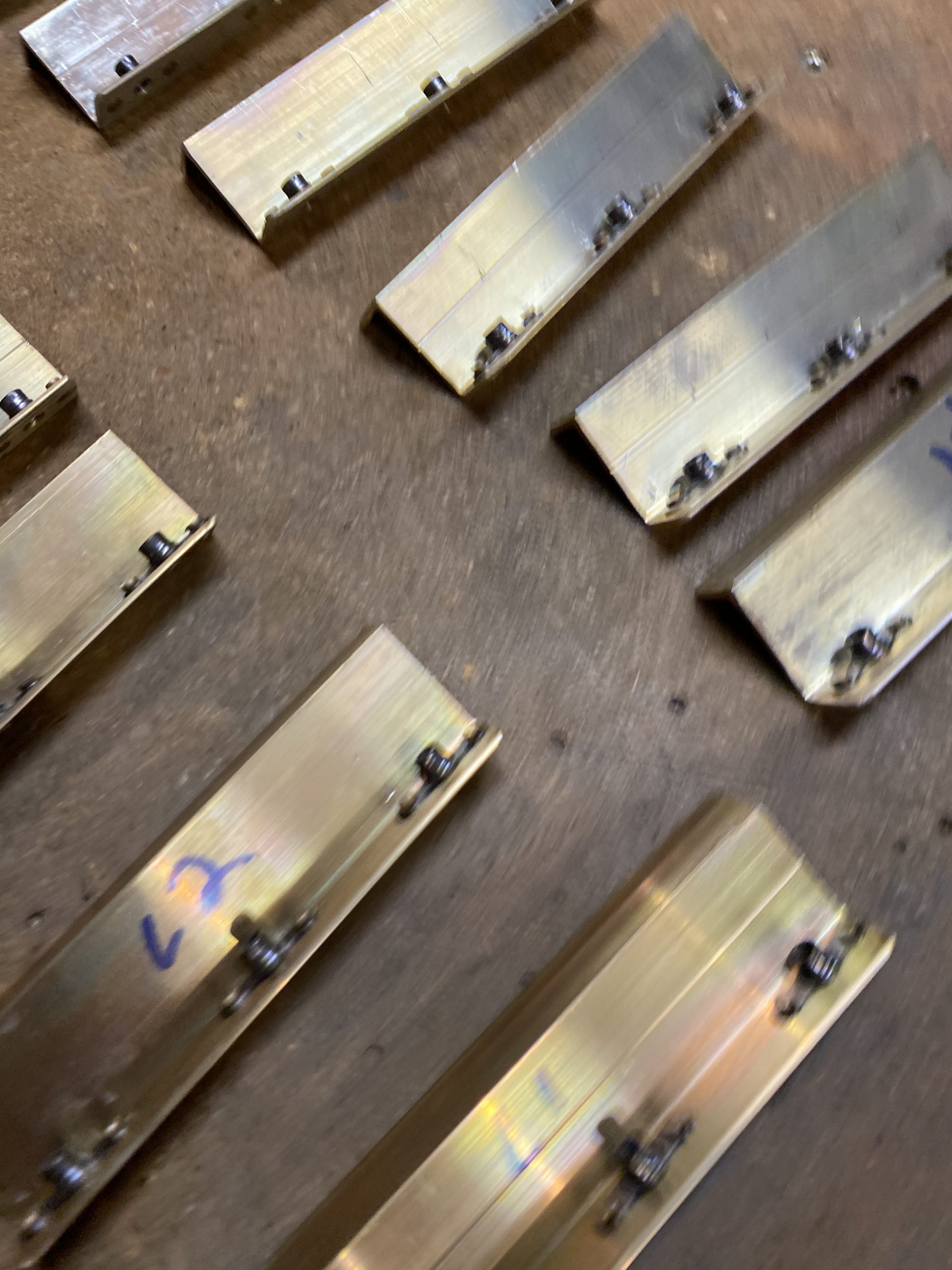
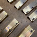
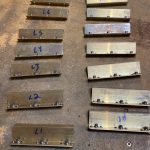
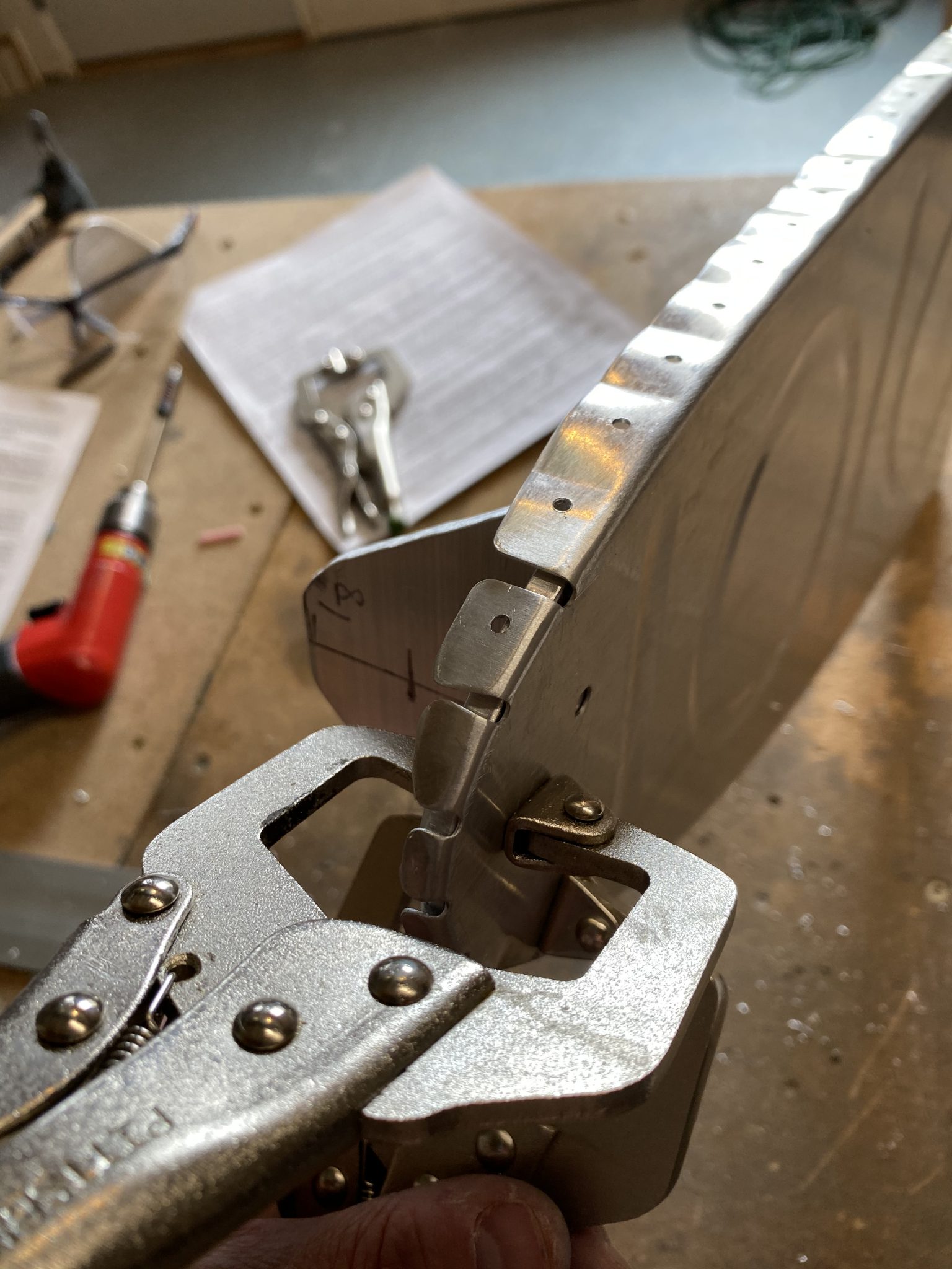
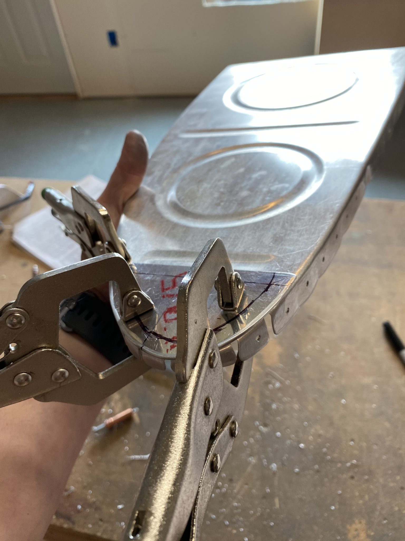
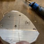
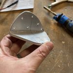
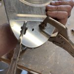
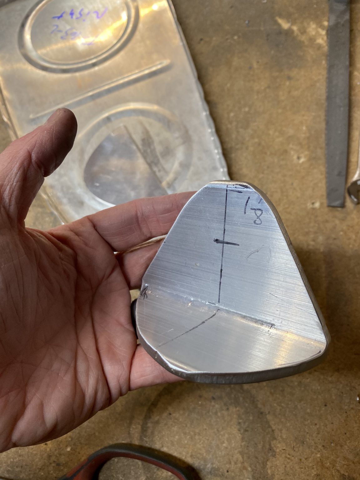
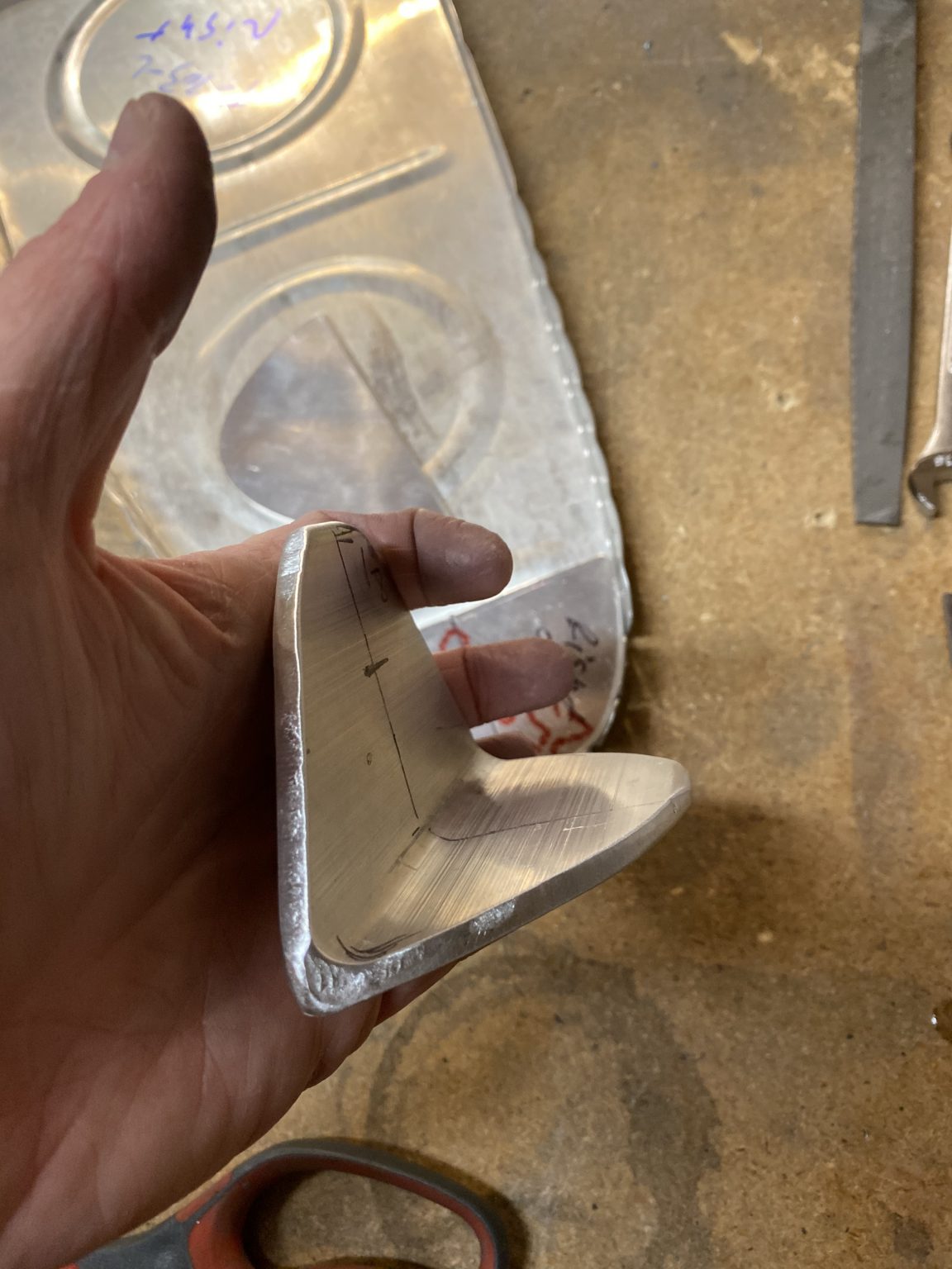
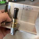
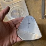
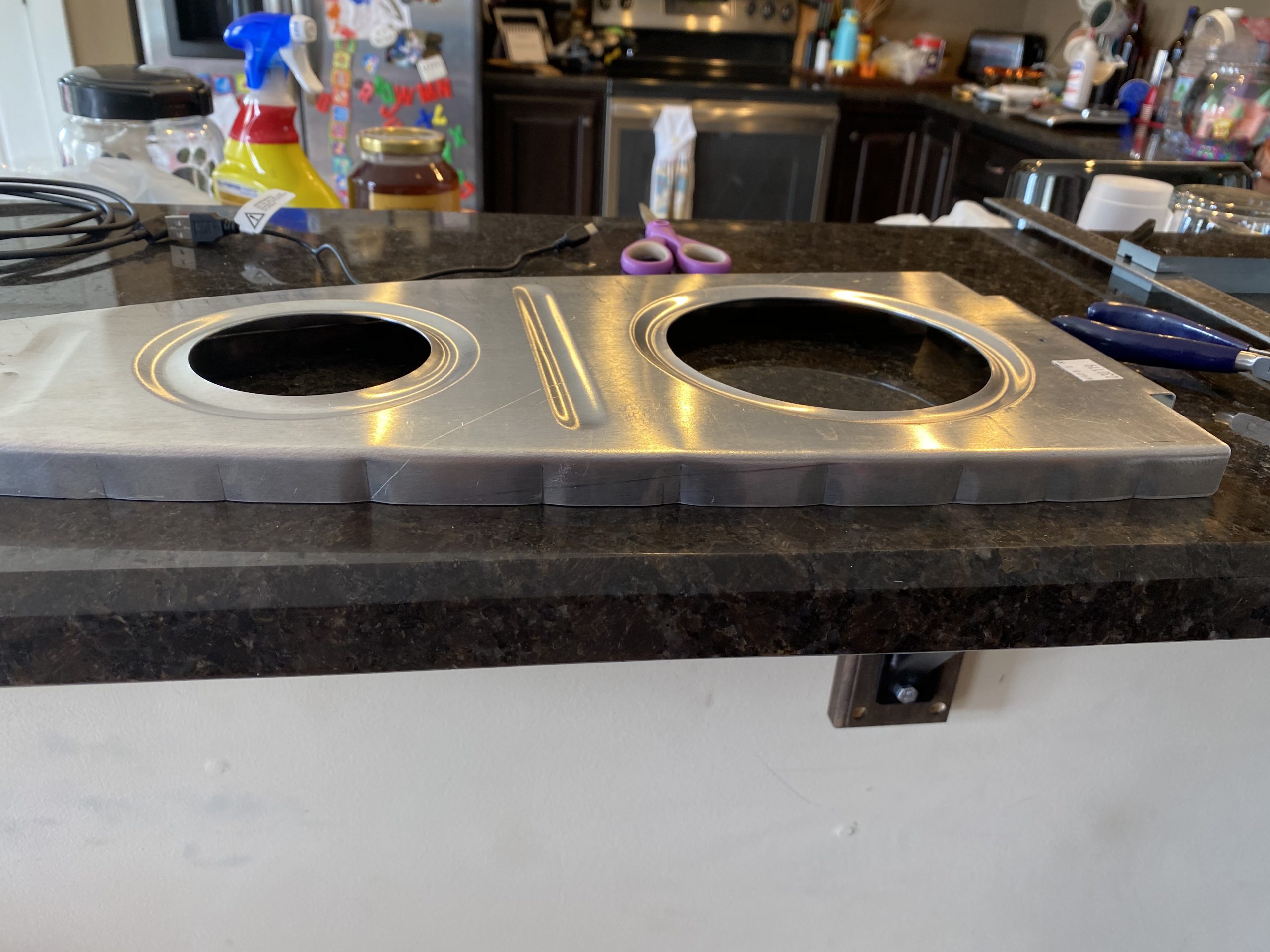
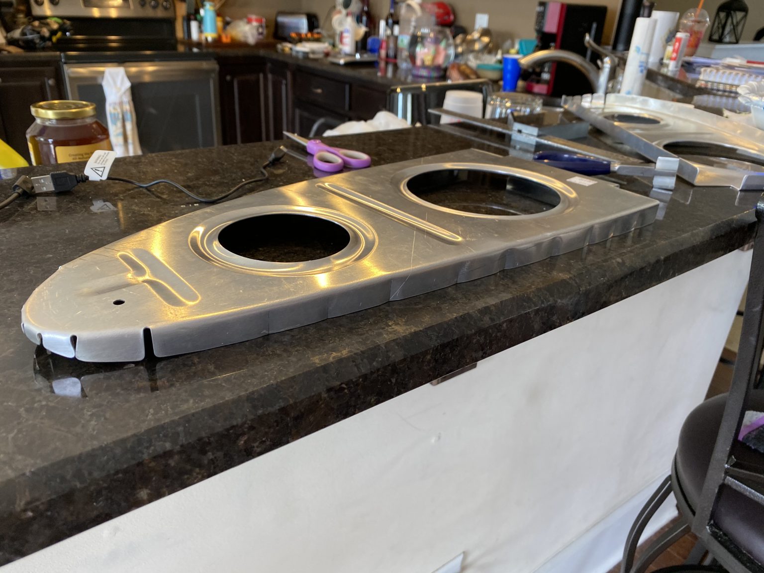
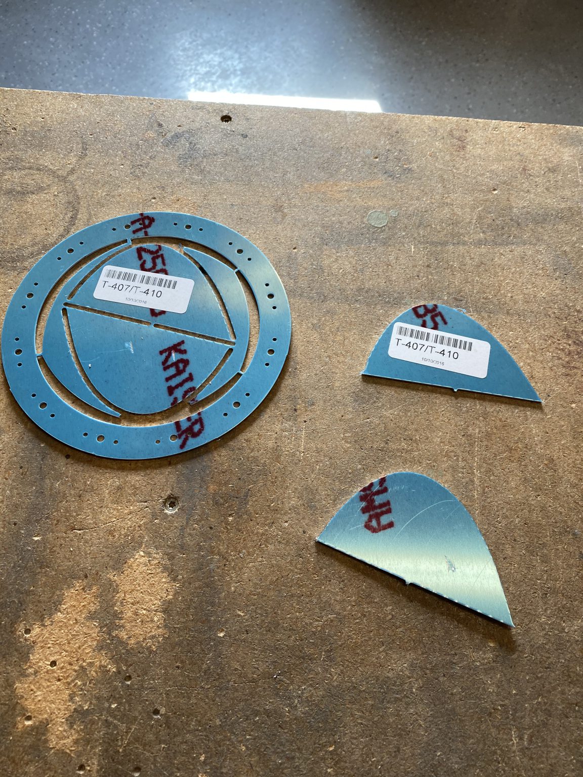
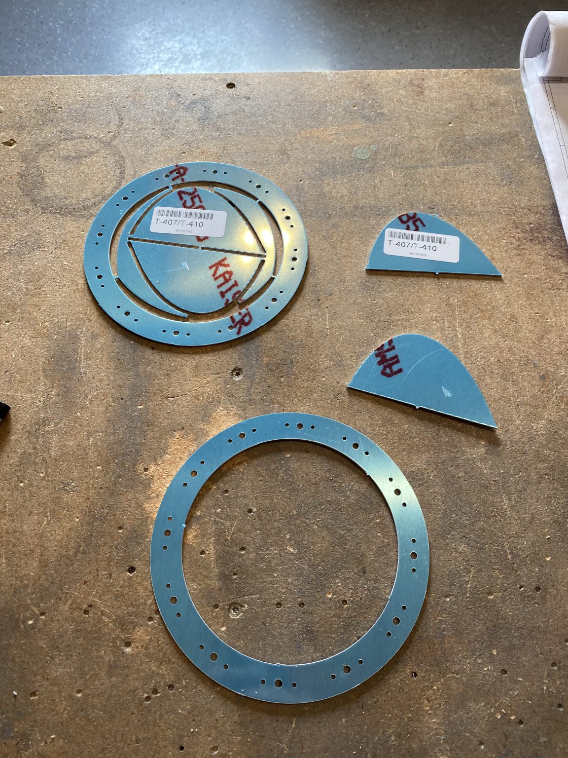
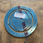
The outboard ribs were much simpler to do, since we don’t have the T-405 angle attach bracket to worry with.  We simple just need to align the T-410 reinforecment plate on the leading edge of the rib, on the inside of the tank, and then choose 3 to 4 rivet holes and drill.  Again, vans doesn’t give much guidance here, so I simply measured for edge distance, gave myself another 1/16″ for a buffer and then tried to space the rivets out in a decent pattern, then drilled the holes through both parts while they were clamped.

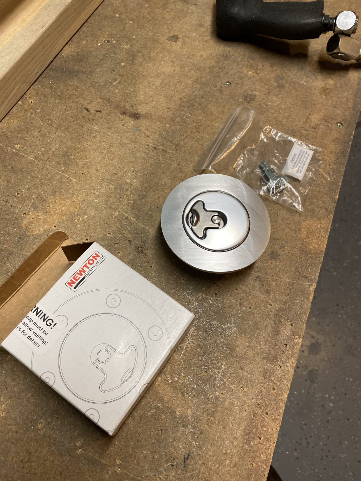
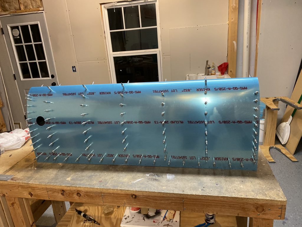
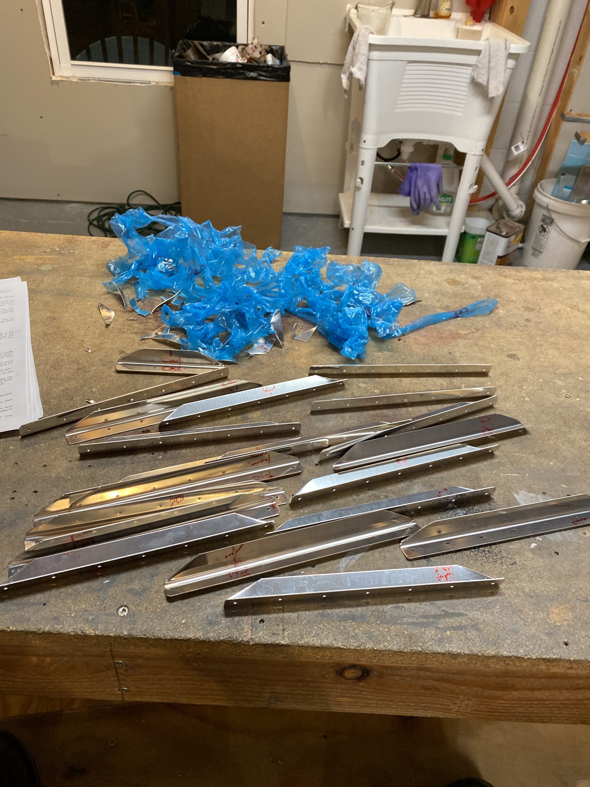
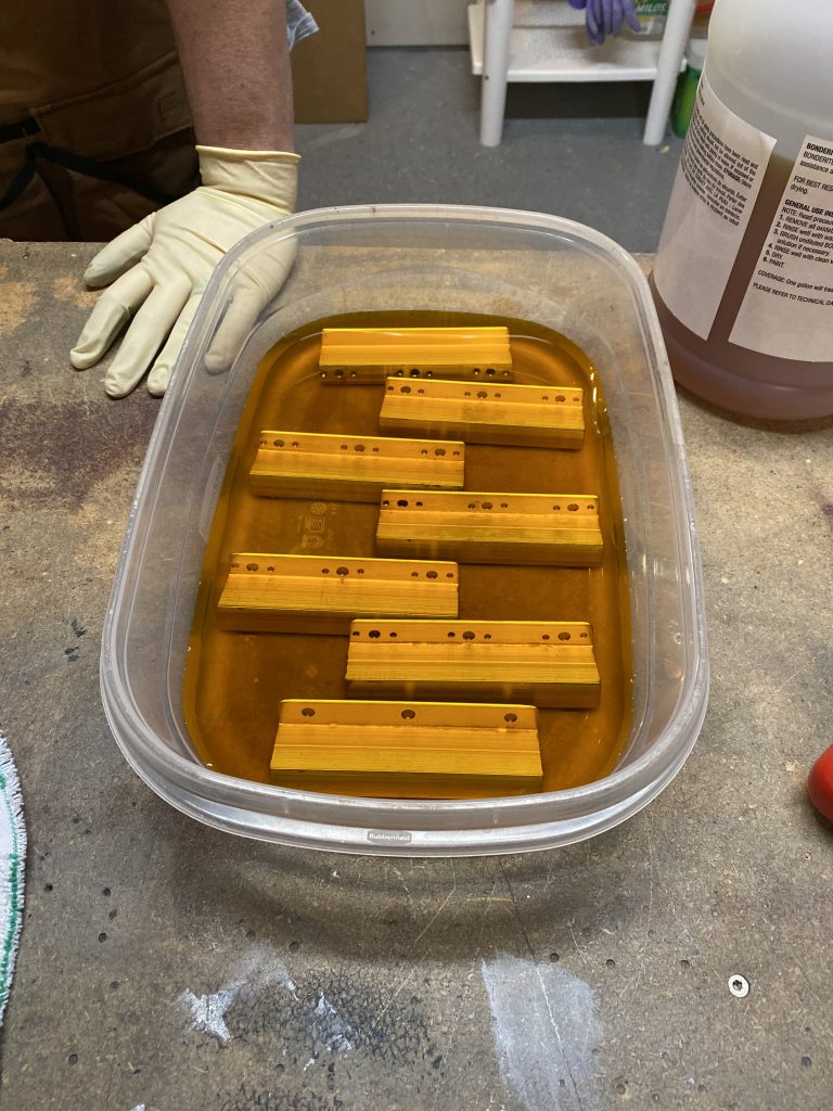
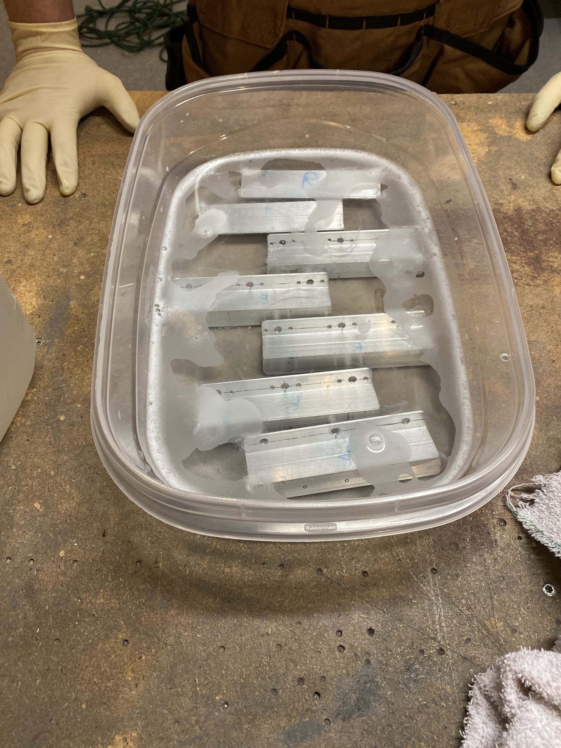
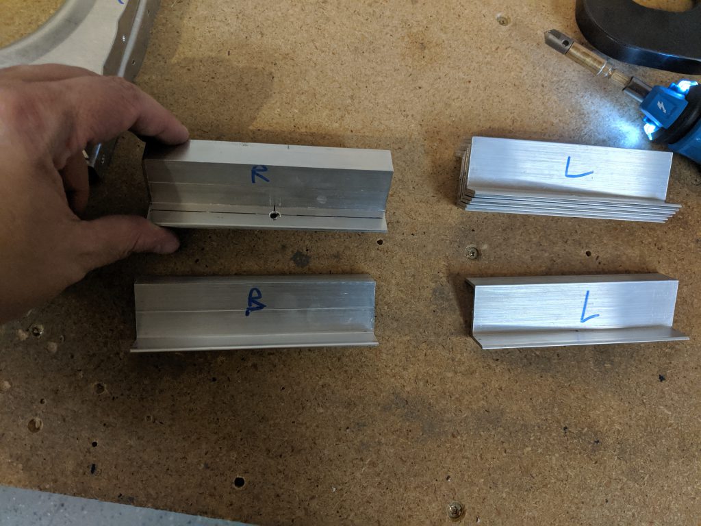
Once the outboard side was drilled, I removed everything and deburred the holes.  I think I did the left tank first, but after I had one tank done, it was time to move on and do the opposite side in the exact same manner.  Like always, the second time goes much faster, and I didn’t take any photos of it, since its the same as the other side.  Time for a quick break for a bite to eat, and then I’ll do another session tonight.  Probably either the capacitve senders, or the flop tube.  These are the fun parts of the build!

  • IMG_0706
    IMG_0706
  • IMG_0707
    IMG_0707
  • IMG_0708
    IMG_0708
  • IMG_0709
    IMG_0709
  • IMG_0710
    IMG_0710
  • IMG_0711
    IMG_0711
  • IMG_0712
    IMG_0712
  • IMG_0713
    IMG_0713
  • IMG_0714
    IMG_0714
  • IMG_0715
    IMG_0715
  • IMG_0716
    IMG_0716
  • IMG_0717
    IMG_0717
  • IMG_0718
    IMG_0718
  • IMG_0719
    IMG_0719
  • IMG_0720
    IMG_0720
  • IMG_0721
    IMG_0721
  • IMG_0722
    IMG_0722
  • IMG_0723
    IMG_0723


Google Photos Link: https://photos.app.goo.gl/WkDGgx4wffPUXRXM7

Hours Worked: 2.0

Fabricating the Tank Attach Angles

Its time to fabricate some parts! I got home from having dinner with some friends and my family, and felt like knocking out a little bit more on the project, so I decided to tackle fabricating the T-405 tank attach angle brackets.  The plans are a bit vague here, as the instructions tell us to simply fabricate the brackets using the drawing in 16A and this is all we have to go on:

Image 2020-02-16 at 12.40.25 AM.png

So I went digging in my parts shelf and pulled out the 2 x 2.5″ 3/16 angle stock that Vans includes in the kit.  Then I marked off a 3 and 3/4″ section and cut it out on the band saw.

Next up, I wanted to cut the radius part out.  This is the part that goes onto the fuselage to bolt the tank on to the aircraft, and after reading a few other builders blogs, it appears there is some flexibility in how these are mounted so we don’t have to worry about alignment issues per se.  To cut the radius, I first marked off the center of the bracket as a reference.  Then I measured the 1″ radius as the plans call for as “R1″ by marking down from the tip of the bracket 1″ This gave me a crosshairs to form my 1” radius around.  I placed the point of a compass on this crosshairs, and started at the top of the bracket and marked with my compass until I was slightly passed a 45 degree angle on each side of the middle line.  This is sort of eyeballing.  Once I had a rough radius, I simple used a straight edge to mark from the stop of my radius down to the corner of the bracket.  It looked like a good angle when I marked it all up, and it looked very similar to what the plans was calling for.  See for yourself:

That took care of the TOP portion of the bracket, but I still needed to mark the bottom portion so it would fit snug against the curve of the ribs.  Vans gives us a T-410 reinforcement plate that is already cut perfectly, and it makes a very nice template to use on the tank angle brackets.  To make sure everything was squared up, I found the center of the T-410 to be right at 2″, so I marked the centerline of that bracket.  The T-405 angle bracket is slightly smaller, and its center line is at 1 and 7/8″ as seen in the plans, so I marked that centerline on the angle bracket.  Next it was just aligning the centerlines of the T-410 and T-405 to make sure they were squared up and in the proper orientation, and then use the T-410 as a template to mark my cuts for the T-405 angle bracket.  Here you can see how I did this using some cleco clamps to hold everything.

And here is what the copied line looks like on the T-405 tank angle bracket after you remove the reinforcement plate that was used as a template.

The next step was to cut these parts along my lines on the band saw.  I used a scrap piece of wood 2×4 to help hold the angle and keep my hands clear. I wished I had gotten some photos of this process, but I didn’t have any free hands, and I was concentrating on making these cuts.  However, its pretty simple and easy to do on the bandsaw, but I’d recommend not letting these be the first thick pieces of metal you make a curving cut on a band saw with if you have no experience.  I’m not a novice with a band saw, but I have made some complex cuts with one on metal, just take you time and go slow so as to not bind the blade.  Remember you can always work you way into the cut pieces at a time if you need to.  I also started OUTSIDE of my marked lines, so I’d have a little extra material to work with on the grinder to finish with.  After I had my rough cuts made, I finished up the parts on the grinder, working away the extra metal until I was right at my marked lines.  Here is what it looks like:

And after a few test fits, and visits back on the grinder I had a part that fit fairly good!  Once I was happy with the fitment, I went back to the grinder and rounded and smoothed all of the edges for the T-405 tank attach angle brackets.  These look like some sort of machined part with the crazy curves they have, but its a simple angle cut and smoothed 🙂

The only thing I am worried about is how I am gonna get to the rivets in the holes around the edge of the brackets (see photo above).  There isn’t much room for the rivet tail in there between the flange inside and the tank angle bracket.  I’ll do some research and see what other builders have done, as well as read ahead in the plans to see if this is going to be an issue.  It may be that I just notch out a little section for the rivet tail to fit into and call it a day.  After getting one bracket made up, I went ahead and moved on and did the same thing for the right tank brackets.  These were pretty much mirrored of each other, so the second one went a little faster than the first.  The plans tells us to go ahead and drill the rivet holes for these parts (T-405 angle bracket, T-410 reinforcement plates and the T-703-L/R ribs), but I am going to wait on that until I am sure about what I want to do about notching them first.  I’ll call it a night for now.

  • IMG_0693
    IMG_0693
  • IMG_0694
    IMG_0694
  • IMG_0696
    IMG_0696
  • IMG_0695
    IMG_0695
  • IMG_0697
    IMG_0697
  • IMG_0698
    IMG_0698
  • IMG_0699
    IMG_0699
  • IMG_0700
    IMG_0700
  • IMG_0701
    IMG_0701
  • IMG_0702
    IMG_0702
  • IMG_0703
    IMG_0703
  • IMG_0704
    IMG_0704
  • IMG_0705
    IMG_0705


Google Photos Link: https://photos.app.goo.gl/77eEx2AzRojMogfLA

Hours Worked: 2.0

Finishing the Leading Edge Ribs

My Vans shipment came in while I was on vacation with the family.  The leading edge ribs I needed were in this shipment, these are the ones that will replace the ribs that had the edge distance issue from where I mis-drilled them.  I also had some proseal, 50ft of nylon conduit and a few other things I wanted to pick up; including the Vans lighted sign 🙂  I’ll build that later, dont want to use up my time on the RV-7 building the sign.

First things first:  In this shipment was one of my missing K1000-3 nutplates that I needed on the aft spar web of the right wing, so I spent a few minutes riveting that nutplate on using the back rivet method.  Once I had that done, I needed to get these new ribs ready to be used.  That meant straightening the flanges, and fluting them, deburring, and all that good stuff.  So, like so many posts ago, I set about deburring the edges of the ribs using my bench grinder, and then a combination of scotchbrite, sanding paper and emory cloth to get all the tiny gaps in the flanges.  Then I used a deburring tool and a scotchbrite to deburr the edges of the lighening holes.   Once they were nice and smooth, I used this handy tool I made a while back to get the flanges to 90 degrees.


Before correcting the flanges

After correcting the flanges

Then it was time to do some fluting to get all the warping out from the forming process. I outline this in detail in previous posts, but here I am using my wifes granite countertop as my flat surface to check the fluting process against:

You can see a big difference!  The top pic is after its been fluted and all corrected. Once I had them all straight and ready to go, I marked the centerlines of the flanges so I could line them up with the prepunched holes in the leading edge skin to make sure I got the correct edge distance, then I back drilled into the ribs using the skin as a guideline.

It’s not 100% perfect, but its close, and there is plenty of edge distance now, so I am happy with the outcome.  I tossed the old ribs into my scrap bucket, maybe I’ll find a use for them in the future?  I then removed the ribs and the reinforcement plate and deburred the holes on both the rib and the plate.  I’ll leave these parts off for now, because I need to alodine them before final assembly.

I wanted to get a little more work done, so back to the tanks! It’s time to make the tank attach brackets.  I separated the T-407 and T-410 from the assembly so I could work on them.  Then I deburred all the edges of these parts on the bench grinder / scotchbrite wheel and labeled them for each fuel tank.

That was it for this session.  Here’s another pic of me, to show I am the guy building the airplane:

And heres an album of all this sessions photos.  I’m headed out to meet some friends for dinner with Acacia and Tammy, and if I get back in time tonight, I’ll continue working.  Next up will be to make the heavy tank attach brackets.

  • IMG_0665
    IMG_0665
  • IMG_0667
    IMG_0667
  • IMG_0666
    IMG_0666
  • IMG_0668
    IMG_0668
  • IMG_0668 (1)
    IMG_0668 (1)
  • IMG_0670
    IMG_0670
  • IMG_0671
    IMG_0671
  • IMG_0672
    IMG_0672
  • IMG_0673
    IMG_0673
  • IMG_0674
    IMG_0674
  • IMG_0675
    IMG_0675
  • IMG_0676
    IMG_0676
  • IMG_0677
    IMG_0677
  • IMG_0678
    IMG_0678
  • IMG_0679
    IMG_0679
  • IMG_0680
    IMG_0680
  • IMG_0681
    IMG_0681
  • IMG_0682
    IMG_0682
  • IMG_0683
    IMG_0683
  • IMG_0684
    IMG_0684
  • IMG_0685
    IMG_0685
  • IMG_0686
    IMG_0686
  • IMG_0687
    IMG_0687
  • IMG_0688
    IMG_0688
  • IMG_0689
    IMG_0689
  • IMG_0690
    IMG_0690
  • IMG_0691
    IMG_0691
  • IMG_0692
    IMG_0692

Google Photos Link:  https://photos.app.goo.gl/hUMoEMcm4FR6FEYB9

Hours Worked: 3.25

Fitting Tank Drains and Fuel Caps

Tonight was a fun build session!  Since all the tank structure is pretty much fitted and done, I needed to knock out the last few little bits of tank parts:  The tank drains (sumps) and the fuel caps.  I’ve been sort of looking forward to doing this work to be honest.  I decided to start out with the easy stuff first and then work till I was tired.  That meant fitting the tank drains (aka “sumps”).  We need to center the VA-112 drain flange over the pre-punched drain hole in the tank skin and use the flange as a guide for back drilling the tank skin.  I didn’t want to eyeball this, so I pulled out my assortment of center punches and found one that was almost the same size as the hole in the drain flange and used it as a guide to center the flange on the skins hole.

Once I had it centered up, I used some vise grip clamps to hold it in place so I could back drill the skins rivet holes using the flange as a guide.  I’d drill a hole, and then insert a cleco immediately in the hole and then move across and drill another hole and repeat the process. This assured I’d have the flange nice and flush on the tank skin and everything lined up.

      .   

After I had the flange drilled, I removed it, and then deburred the rivet holes with a deburring tool, and done the exact same process to the other tanks flange.  The flanges shipped machine countersunk, so I didn’t have to do any countersinking on them, but I did check their depth by inserting a rivet and making sure the head would be nice and flush.  I decided to start working on the next cool part:  The fuel caps.  I had ordered the upgrade Newton style “Deluxe” fuel caps when I ordered my wing kit, from the suggestions of many other builders, and these things are AWESOME!

They ship with a nicely machined flange that is shaped to fit the inside curvature of the tank skin, making fitting them pretty easy.  On these, the tank skins have pre-punched holes for both the fuel filler hole, as well as the rivet holes that is used to rivet the machined T-406B flange onto.  I decided to put my tanks in the stands and cleco in three of the outboard ribs to help the skin hold its correct shape, that way I could get the machined curve in the flange exactly right.

Now it was a matter of lining up the machine parts of the flange with the curve of the tank skin and then using the actual fuel cap as a guide to help center everything up on the pre-punch fuel filler hole in the skin.  Once I had everything lined up, I used some C-clamps to help hold the flange in place so I could get the first holes done.

.

After I was happy with the alignment, I then started back drilling into the T-406B flange using the tank skins pre-punched holes as my guides.  Like always, I’d drill a hole, then insert a cleco into that new hole to help hold everything tight before moving on to drilling the next hole.  I only removed the clamps at the very last moment.

And VOILA! This his how it looks when its all said and done. I can’t tell you how good and how flush these fuel caps are!  They are really sexy and are very well made.  I’m also very happy with just how well sized the pre-punched filler hole was in the skins, as I didn’t need to do any sort of work on the skins hole to get everything lined up. It really made this look like a completely professional install.


You can see how well the flange’s machine curve fits against the skin! I also marked the flanges against the skins so I could get them returned to their correct orientation when it comes time to rivet them on.

And here’s a quick little video of how well they look and work:

Once I had all the holes back drilled into the flange, I went ahead and deburred the new holes in the flanges, and then used my micro stop countersink to countersink the holes in the TOP part of the flange so they could receive the dimples that will be going into the tanks skin.  I adjusted the countersink so that it would do a little deeper into this part as its very thick, and I wanted to give plenty of room for the dimple in this .032″ tank skin, and also leave room for some proseal to goop in the dimples for sealing.  Once I had one tanks fuel cap done, I did the same exact process on the others wings fuel tanks.

The last little step I enjoyed pretty well.  I needed to fabricated the T-714 clip for the vent line out of some 0.025 x 1/2″ wide sheet.  I dug in my scrap bucket, and found a nice sheet of alclad in 0.025, and marked out a 1/2″ wide strip along the edge, and then cut it off with my snips.

Once I had my strips cut, I had to form them into the shape that is denoted on the plans like this:

Next I marked a centerline on the strip so I could get the rivet hole just right, and then placed the centerline on the T-406B flange rivet hole to mark the hole onto the strip where I’d need to drill into it for its mounting hole.  Then drilled it with a #40 drill bit to match the flange, and formed a rough bend line to get an idea of what I should do.

Before going to far, I deburred the edges using my bench grinder and then rounded all the corners to prevent any stress cracks. For the bends, and even for the loop in the clip, I used a handy set of forming pliers to get nice and straight bends.

I then formed the loop in the T-714 clip using the aluminum tubing that will eventually be the vent line, as well as the forming pliers until I was happy I had a nice loop to hold the vent tubing.

Once I had one completed, I went ahead and done the other tank’s T-514 clip in the same manner, making sure to deburr the rivet hole and deburr the edges.  These turned out better than I had expected, and I am a little proud of how they ended up looking!  Too bad they’ll be in the tanks where no one will ever see them.  Hah!  That was enough for tonight.  That completed the cap and drain system for the tanks.  I still have a little more fabricating to do on some other tank parts, but thats for another session!  Here’s all the photos from tonights work:

  • IMG_0579
    IMG_0579
  • IMG_0580
    IMG_0580
  • IMG_0578
    IMG_0578
  • IMG_0581
    IMG_0581
  • IMG_0582
    IMG_0582
  • IMG_0583
    IMG_0583
  • IMG_0584
    IMG_0584
  • IMG_0585
    IMG_0585
  • IMG_0586
    IMG_0586
  • IMG_0587
    IMG_0587
  • IMG_0588
    IMG_0588
  • IMG_0589
    IMG_0589
  • IMG_0590
    IMG_0590
  • IMG_0591
    IMG_0591
  • IMG_0592
    IMG_0592
  • IMG_0593
    IMG_0593
  • IMG_0594
    IMG_0594
  • IMG_0595
    IMG_0595
  • IMG_0596
    IMG_0596
  • IMG_0597
    IMG_0597
  • IMG_0598
    IMG_0598
  • IMG_0600
    IMG_0600
  • IMG_0601
    IMG_0601
  • IMG_0602
    IMG_0602
  • IMG_0603
    IMG_0603
  • IMG_0604
    IMG_0604
  • IMG_0605
    IMG_0605
  • IMG_0606
    IMG_0606
  • IMG_0607
    IMG_0607
  • IMG_0608
    IMG_0608
  • IMG_0609
    IMG_0609
  • IMG_0610
    IMG_0610
  • IMG_0611
    IMG_0611
  • IMG_0612
    IMG_0612

Google Photos Link:  https://photos.app.goo.gl/QACsSYvKd9Rra7877

Hours Worked: 3.5

Match Drilling the Left Tank

More Fuel tank work!  Tonight I wanted to get the left fuel tank match drilled and then disassembled so that I could begin working on deburring the parts and getting them ready for final assembly.  I already had the left tank off the wing and on the bench from my last session, so I started in by match drilling all the 3/32″ holes.

Once I had those done, I then started on countersinking the rivet holes that run the length of where the skin attaches to the rear baffle, as per the instructions.  We countersink these so that its easier to slide the baffle in place with the wet sealant during assembly.  If we had dimpled these, it would be much more difficult to do this evenly.  The micro-stop countersink was already setup for the proper depth, so I made quick work of those holes.  Next up was to open the screw holes that attach the skin to the spar and the W-423 strip to a #19 hole.  Once I had all the holes match drilled, I labeled where the parts were clecoed, disassembled the tank and set its parts on the shelf to be later deburred and finished.

There was one more step I needed to complete before moving on for the night, and that was riveting the nut plates to the spar web that are used for the most inboard tank attach bracket.  These are placed on the BACK side of the spar web, so that its easier to bolt the tank into place.  There are three pre-drilled holes in the spar web; one for each nutplate.  I simply clecoed them into place and match drilled the holes.

We need to attach these with AN426AD3-4 rivets so the head will sit flush on the spar web, so that the tank attach bracket can sit against the spar web.  So I used the microstop countersink, as it was already setup for the tanks depth and countersunk the holes.  Except I ran into an issue:

As you can see in the photos above, there wasn’t enough clearance between the spar reinforcement bars to get the pilot into the holes on the upper and lower nutplates.  So I got a bit creative.  I used a deburring tool in my power driver and very gingerly countersunk the holes, checking the depth every so often with a rivet until I had the rivet sitting flush:

This worked pretty good.  Then I clecoed on the nutplates, and riveted them using the backrivet method.  I used the back rivet tool in my rivet gun to press against the tail of the rivet from the inside of the wing and then the bucking bar on the flush head and bucked from the top.  This worked out really well.


I finished up the left wing, then moved on to the right wing, when I noticed:  I am SHORT by one K1000-3 nutplate!  I didn’t have enough to finish the last hole.  I need to get an order in to Vans anyways to get some proseal and other things on their way, because we are very close to sealing up these tanks!  So thats where I left it for the night: One nutplate short!

Google Photos Link: https://photos.app.goo.gl/vZy9N7VWABo1qbz78

Hours Worked: 3.25

Match Drilling the Right Fuel Tank

Had a really good build session tonight, and made some really great progress on my fuel tanks.  To pick up from where I left off last, I needed to back drill the tank ribs to the baffle and into the tank attach brackets.  I used my 12″ long #30 (1/8″) bit to back drill all the holes.  This worked well and I had plenty of room to work.  at 16″ probably would have been much better.

Next, I needed to remove the blue plastic from the inside of the T-701 tanks skins so to start the match drilling process.  I started on the right tank, and pulled the plastic off, then cleco’d on the tank stiffeners.  Just a side note, when you are cleco’ing the stiffeners on, dont use the very edge holes on the stiffeners and the clecos will give you a hard time around the ribs.  I had to move my clecos to make slipping the skin on a little easier. I also numbered the stiffeners and their location on the skins to make them easier to get in the right spots on re-assembly.

Then I slipped the skin over the ribs and clecoed it down.  PRO-TIP:  Start clecoing it down from the BOTTOM side of the wing, working your way from the center outwards and then around the leading edge and back down the TOP of the tank working towards the spar.  I fought with trying to do it the other way and it was a hassle!  Starting on the bottom side made it much easier. Heres the left tank clecod on as an example.  I only had enough clecos to do one tank at a time though.

Once the skin was compeltely clecod down to the ribs and baffle, we needed to back drill the W-423 plate using the tank skin as a guide.  We use a #30 bit at first to get the holes where we want. You can see the newly drilled holes in between the row of clecos in the photo below:

Once we have those holes drilled, we take the tank off the spar, completely assembled.  So, I unbolted the tank attach brackets from the spar, and moved it over to my bench to avoid match drilling into the expensive wing spar!  As is the usual process, I used a reamer to match ream all the pre-punched holes in the skins to the ribs and the baffle.  This worked out pretty nice as the bench had it at a good working height.

The next step we need to do is machine countersink the rivet holes that attach the skin to the baffle.  We do this so that we can easily and cleanly slide the baffle into place with it gooped up with Pro-seal. Dimpling would make this a much harder process.  I fired up the micro-stop countersink and confirmed the depth.  Per the instructions, I left the baffle clecod on to serve as a stable pilot hole for the countersink.   This took some time as there are a bunch of holes!! My countersink got pretty warm during this process, so I had to give it (and my hands!) a few breaks in between.

After countersinking the baffle row, I removed the baffle, as I needed to shift some ribs and flanges a tiny bit to backdrill the last few holes.  I didn’t snap any pics of this process, but I simply had to work the ribs around with my hands till the holes lined up and then ream them to size.  After that, the plans has us drill the W-423 screw holes as well as all the spar attachement screw holes up to a #19 size.  I got this done on the right tank.  After that, we mark all the parts so we can get them back in their places on assembly, and then disassemble the tank for deburring, and edge finishing.  Heres my right tank, and all its parts on the shelf waiting for this finish work:

That completed the layup for the right tank, and I had a little more steam left in me, so I started on the left tank.  I followed the same process as above, but I didn’t quite get to the match drilling portion yet.  I was able to get the left wing skin clecoed onto the baffle and ribs, the W-423 holes back drilled, and then the tank removed and on my bench waiting on the match drilling and countersinking to start. That was a good stopping point for the night, and a good place to pick back up on the next session.  Heres a photo of me with my wings to prove I’m the guy building it 🙂

Here’s a link to the Google Photos album for tonights work:  https://photos.app.goo.gl/gnJS9QctFQNqoJAr7
And heres all the photos for tonight:

  • IMG_0565
    IMG_0565
  • IMG_0550
    IMG_0550
  • IMG_0552
    IMG_0552
  • IMG_0553
    IMG_0553
  • IMG_0551
    IMG_0551
  • IMG_0554 2
    IMG_0554 2
  • IMG_0555
    IMG_0555
  • IMG_0556
    IMG_0556
  • IMG_0557
    IMG_0557
  • IMG_0558
    IMG_0558
  • IMG_0559
    IMG_0559
  • IMG_0560
    IMG_0560
  • IMG_0561
    IMG_0561
  • IMG_0562
    IMG_0562
  • IMG_0563
    IMG_0563
  • IMG_0564
    IMG_0564

Hours worked: 6.25

Making the Tank Stiffeners

Tammy and Acacia went on a “Girls Night” with my mom and sister to Knoxville, and they’ll be gone overnight, which freed me up to do some work on the RV-7 tonight.  The work for tonight started with making the tank stiffeners from the provided punched and notched stock.  These are the T-711 A through D stiffeners for each tank.  They were pretty easy to cut from the stock using a pair of snips and going along the notches to indicate where to cut.  This is similar to the stiffeners used in the control surfaces, so its very familiar work.

And here’s the pile of stiffeners, cut out and ready to take to the bench grinder for deburring:

I spent about 20 minutes or so on the bench grinder working these stiffeners on the scotchbrite wheel to deburr the edges and smooth out the cuts I made. They came out looking pretty nicely.  Since these are going inside the tank, they will NOT get any sort of primer or alodine.  I will clean them with acetone before I bond them with proseal and rivet though.  Next the plans tell us to cleco the stiffeners to the tanks, and match the drill the holes.  All of these are different sizes (A through D) but Vans offsets the rivet holes making it a simple task to find the right ones and get them in the right spots.

After I had those all match drilled, the next thing was to put the T-701 tank skins onto the baffle and check the fit on the wings. I did this a little differently, as I wanted to make sure I had all my holes lined up on my baffles.  I clecod the baffle to the T-701 skins and then mounted the assembly onto the wing checking alignment.  I then clecod the skin assembly to the main spar to make sure it was steady.

Then I reached in from the side, and marked the holes onto the tank attach brackets using the baffle as a guide after I made sure the centerlines from the tank attach brackets were showing in the center of the pre-punched holes in the baffles.  I marked as many holes as I could reach, and pulled the assembly off to check my alignment:


It’s not EXACT, but its very close! Once I was happy with the alignment, I clecoed the baffle back down to the tank attach brackets and then backdrilled into the brackets using the remaining holes in baffle as a guide.  I ONLY drilled the center hole in the brackets, leaving the other 4 holes for later, as prescribed by the plans.

Now that the baffle had enough holes to cleco it down to the attach brackets, it was time to start cleco’ing on the ribs!  Once the ribs are on, I will backdrill the ribs, baffle, and tank attach brackets together using the rib holes as guides.  I clecoed on the ribs, double checking their placement with the plans.

I was pretty spent after clecoing the ribs on, so I decided to call it a night, and do the backdrilling when I was fresh.  Of course, I did this same set of procedures on the other wing, I just simply showing photos from one wing in the blog post 🙂 . Heres all the photos from tonights work:

  • IMG_0517
    IMG_0517
  • IMG_0516
    IMG_0516
  • IMG_0515
    IMG_0515
  • IMG_0514
    IMG_0514
  • IMG_0512
    IMG_0512
  • IMG_0511
    IMG_0511
  • IMG_0510
    IMG_0510
  • IMG_0513
    IMG_0513
  • IMG_0507
    IMG_0507
  • IMG_0509
    IMG_0509
  • IMG_0506
    IMG_0506

Google Photos Link: https://photos.app.goo.gl/z1bQgQJa14SmSxr19

Hours Worked: 3.5

Tank Attach Brackets Part 2

WHAT? I’m actually getting something done on the RV-7?  Yep.  Thats right, I found some more time to work on the airplane tonight. This new position at work has been keeping me busy, but I think I am going to have more time to work on the airplane since I will be traveling a lot less.  I have been briefing up where I left off this past week, so I am not adding those hours into the build.  I need to get these tank attach brackets finished up so I can continue with the tanks.  So, I pulled the brackets off the wings so I can drill the nut plates and deburr them.  I marked the locations so I could get them exactly returned to where they came from, and then started on the nut plates.  I don’t have a nutplate jig, so I had to make do with my tools on hand.  I used an AN3 bolt to thread into the K1000-3 nutplates so I could line up the “ears” on the nutplates with the centerlines I had drawn on the brackets.  Then, while holding the nutplate in this position, I drilled one of the holes.  After the first hole was drilled, I stuck a cleco in to help hold it all squared up for the last hole to be back drilled.

I used some clamps to help hold the bracket on my table as I drilled. Eventually I turned this into an assembly line:

Once I had all 12 (6 on each side) of the tank attach brackets drilled for the nutplates I moved on to deburring all the holes, as well as all the corners and edges to make them nice and smooth.  On the front side of the nutplates, they are attached with AN426 flush rivets, so I needed to countersink the holes for a nice smooth fit on the side of the tank attach brackets that gets bolted to the main spar web.  I used my clamps again to hold the brackets to the table, and then fired up the micro-stop countersink and adjusted the depth so the rivets would sit nice and flush.

I again, turned this into an assembly line, by clamping several brackets to the table and doing the countersinks all in one run 🙂 Once I had all the countersink done, I decided to go ahead and Alodine these parts.  I’m not going to prime them, since a good Alodine coating will be plenty of protection.  I got my dunking tanks out and started the process. First up, cleaning them with Alumaprep 33:

Then after a quick rinse to rid then of the Alumaprep, I dunked the in the Alodine bath for about 10 minutes:

Heres a shot of me doing the work to prove I am the dude building the plane.  You might notice that I have lost a good bit of weight!  Nearly 83 pounds to date, all from eating 1800 calories per day and doing a ketogenic diet.  It feels pretty amazing, but this blog isn’t the place to discuss dieting, unless we are measuring the gain in useful load 🙂

Now that the parts are Alodined, i went ahead and riveted on the nutplates.  I clecoed one hole of the nutplate to hold it, while I used the Numatix rivet squeezer on the rivets.  This made quick easy work of them, and in not time, I had 12 tank attach brackets all ready to go!

The plans tells us to go ahead and bolt these onto the main spar web using the AN304 bolts, and a washer (the size escapes me currently, but I did find the correct size on the plans).  I am not sure why we bolt all three bolts for each bracket, as they’ll need to come off again to rivet them onto the baffle.  So, I just used two bolts per bracket and got them snugged up onto the spar web for alignment purposes in the next step,  These will be coming off in the near future when we seal up the tanks.  I’ll reinstall them with all the bolts and apply proper torque values and then some paint some torque seal on them.  Here’s how they look for now:

This was a long working session!  Even though it doesn’t look like much was done, there was a lot of work in those nutplates! From here I’ll fit the baffle and the tank skins.  Heres all the photos from tonight:

  • IMG_0464
    IMG_0464
  • IMG_0463
    IMG_0463
  • IMG_0462
    IMG_0462
  • IMG_0461
    IMG_0461
  • IMG_0460
    IMG_0460
  • IMG_0459
    IMG_0459
  • IMG_0458
    IMG_0458
  • IMG_0457
    IMG_0457
  • IMG_0456
    IMG_0456
  • IMG_0455
    IMG_0455
  • IMG_0454
    IMG_0454
  • IMG_0453
    IMG_0453
  • IMG_0452
    IMG_0452
  • IMG_0451
    IMG_0451
  • IMG_0450
    IMG_0450
  • IMG_0449
    IMG_0449
  • IMG_0448
    IMG_0448
  • IMG_0447
    IMG_0447
  • IMG_0446
    IMG_0446

Google Photos Link:  https://photos.app.goo.gl/ccsAmu7qk7K5dn8k6

Hours Worked: 4.75

Drilling The Tank Attach Z-Brackets

Time to drill the tank attach Z-brackets.  I swung by Ace and picked up some cheap 10-32 bolts, nuts and washers to temporarily hold the brackets to the spar for back drilling.  These will get tossed for the final assembly, they’re just used to help steady the bracket for precise drilling.  I actually had my little helper Acacia tonight for a little while.  We stuck a bolt, and washer in each bracket and then put them on the spars.

Then I squared up the brackets to the spare to make sure they were perfectly aligned.  My little helper gave up and got bored so she went back upstairs to play with her dolls.  But I managed fine on my own. HAH.  I used the cheap nuts and bolts in the center hole to tightly hold the bracket to the spar so they wouldn’t move when I was back drilling them form the other side of the spar.

I used a small square to make sure the brackets were lined up perfectly perpendicular with the spar.

Once I had all of the brackets installed and squared, I tightened the bolts down and then double checked them with my square to be sure they didn’t move.  I did the same to both spars.  Next up was to back drill the other two holes in the brackets by using the pre-punched holes in the spars as a guide.  Unfortunately, I didn’t snap a pic of the back drilling process, nor the final results.  I’ll get a photo of them in the next build log.

I wanted to make sure I had things correct before moving on to the next step, so I slipped the baffle onto the right tank skin and then placed the assembly onto the wing so I could check that the prepunched holes in the baffler were lining up with the centers of my tank attach brackets.  Heres the baffle installed on the skin, in my jig.

And here’s the assembly cleco’d onto the wing.  The alignment was really good, and the prepunched holes were lining up nicely on the center of the tank attach brackets.  Its starting to look like a real wing now!  Now, you can see the bulging in the skin where the fuel filler is.  That is because I do not have the internal ribs installed.  This was merely a test fit to see if the baffles lined up on the center of the tank attack brackets.   The tanks will come off before I do any more drilling 🙂

I was pretty happy with the results so far, and decided to call it a night.  I’ll take the tank assembly off in the next build log, remove the attach brackets and drill their nut plate holes.  Once I have all the nut plate holes drilled, I will probably prime them, and then install them onto the spar for the next steps.

Heres the Google Photos album: https://photos.app.goo.gl/8tAeECZ8mQ5VSsi36

And heres all the photos from the build session:

  • IMG_20190916_205726
    IMG_20190916_205726
  • IMG_20190916_205720
    IMG_20190916_205720
  • IMG_20190916_205713
    IMG_20190916_205713
  • IMG_20190916_204213
    IMG_20190916_204213
  • IMG_20190916_204209
    IMG_20190916_204209
  • IMG_20190916_204207
    IMG_20190916_204207
  • IMG_20190915_191643
    IMG_20190915_191643
  • IMG_20190915_190015
    IMG_20190915_190015
  • IMG_20190915_190009
    IMG_20190915_190009
  • IMG_20190915_190000
    IMG_20190915_190000
  • IMG_20190915_183925
    IMG_20190915_183925
  • IMG_20190915_183922
    IMG_20190915_183922
  • IMG_20190915_183918
    IMG_20190915_183918
  • IMG_20190915_183913
    IMG_20190915_183913


Total Time spent: 2.75 hours


Drilling the Fuel Tank Z-Brackets

4 months?  Has it been that long since I last done any work on this thing?   Yep. It has.  I decided to mozy down to the shop to get a little work done on the plane tonight.  I have been busy with work, family and travel, and the Cardinal, that I just haven’t had any spare time to work on the build.  I got down to the shop and first had to do a little housekeeping as it had gotten cluttered over the 4 months.  I’m not counting that time in the build though.  After I got things organized into my “shop” again, I decided I’d pick up where I left off.  The Z-brackets.

In my last post, I also said I needed to place an order with Van’s to replace the messed up W-408 end ribs.  I am going to get that order placed tonight / tomorrow and also toss in the pro-seal and some other bits and bobs I need to complete the last little pieces of the leading edge and stall horn.  It won’t impede progress of the next step or the fuel tanks thank goodness.  I started off by doing lost of refresher reading, including some videos on Youtube and looking over Mike Bulloks post about them.  Folks seem to have the best results using the Checkoway method, which I was I did as well.  I measured 11/32″ from the outside edge of the web on the Z-bracket and made my centerline.  This lets the nut plates (the ones used to bolt the tank to the spar) get as close as possible to the web to give you more room on the opposite side of the web to pull the blind rivets that go into the baffle.

Once the centerline was done, Vans has us mark and drill the very center lengthwise for our first bolt hole.  My Z-brackets were 4.5″ long, so I marked my hole at 2.25″ using my square.

There are 7 brackets for each wing/tank.  We are only going to drill these 11/32″ holes in 6 from each side, as the inboard z-bracket is mounted a little different.  So, for now, I jigged these 12 brackets up in my drill press and drilled the holes with a #12 drill bit.  Coincidently, I noticed my drill quill also had a bit of wobble in it, so I spent probably a half hour trying to adjust it out.  I got it good enough for now, but not where I want it.   I’ll use this guide when I have some spare time: drill_press_tune-up

The holes came out good enough for me. These will get an AN3 bolt, and like Mike Bullock, I decided I will use a spare AN3 bolt, washer and nut to temporarily clamp them down on the spar and use a square to get them lined up perfect so I can back drill the other two holes in the Z-brackets.  BUT….of course I didn’t find any junk or spare bolts in my bins or garage to use, so I will hold that for another build session.  I did get all the 12 brackets center holes done though:

And that is where I’ll stop tonight.  I’ll run by Ace and get a couple of AN3 sized bolts, nuts and washers to use to hold these to the spar for back drilling.  I don’t want to use the “official” hardware for that.  I’ll save those for the real assembly.  I’m headed for Houston tomorrow (on Labor Day no less!) for work so it might be another week or so before I get back after it.

Google Photos Link: https://photos.app.goo.gl/ZLrsMNSYi8q7DLtL8

Hours worked: 2.25