Aileron Pushrods and Control Tubes – Part 2

A long working session tonight with the help of my wife.  We managed to get all the aileron control pushrods and control tubes made up, except for one last little bit of priming, since we ran out of primer.  I did manage to capture the first three hours of the build session in timelapse, but my timelapse stopped at three hours, and we actually worked 4.25 hours.  Oh well.  Here’s those videos:

And heres’ the bench-view:

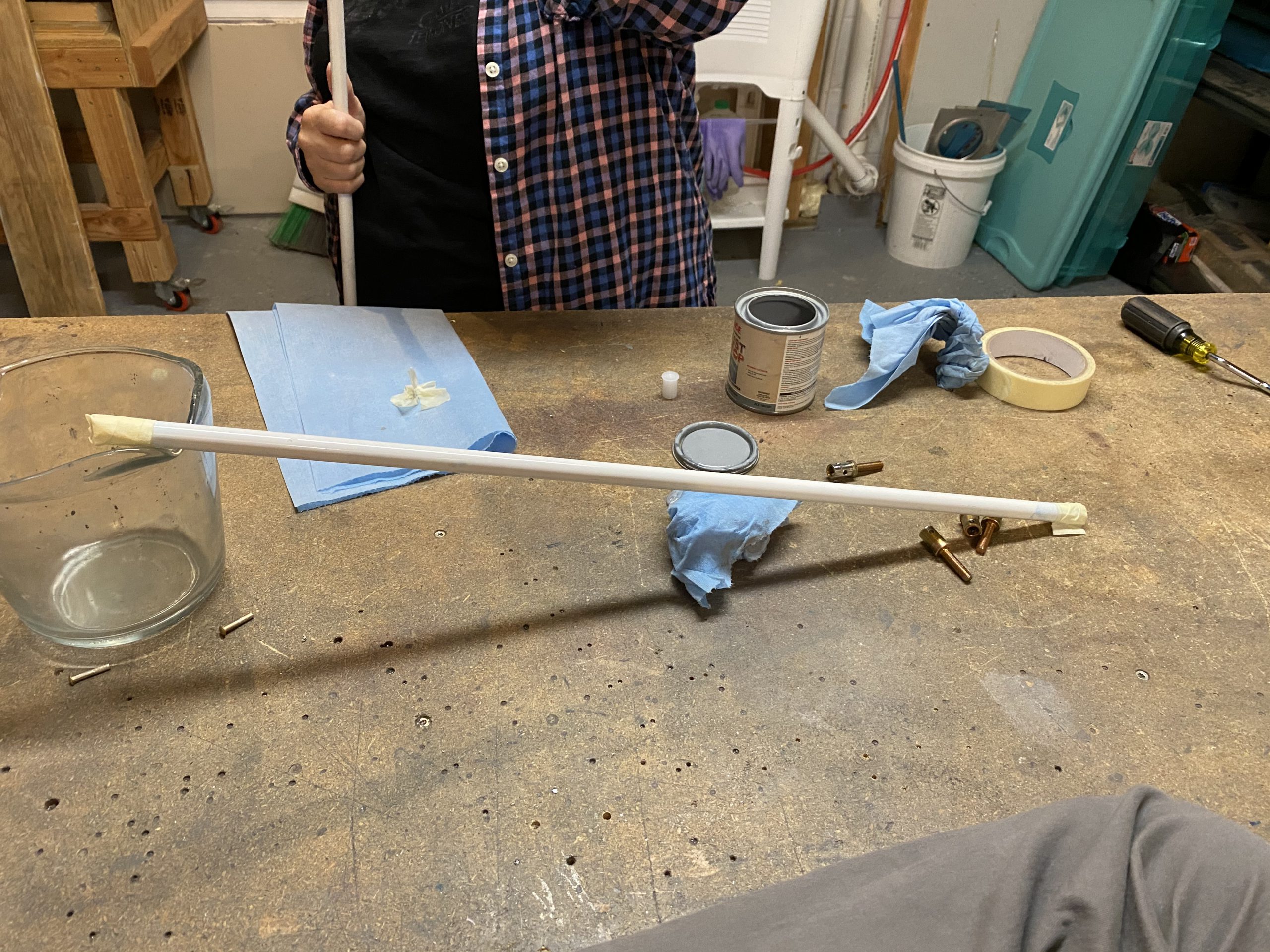
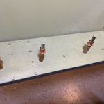
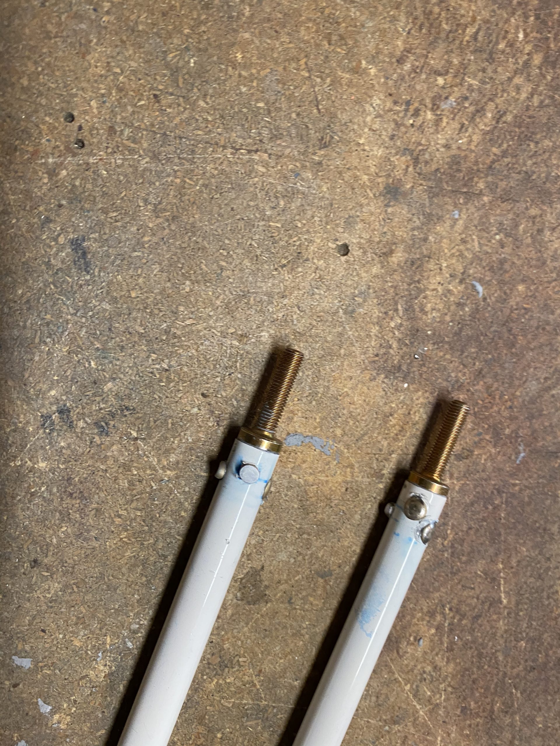
I started out by finishing up the W-818 bellcrank pushrods.  They were left drying overnight from having the inside primed. I grabbed them from the bench, and smeared primer on the AN490-HT8P threaded rod ends, then inserted them and bucked the rivets for them.

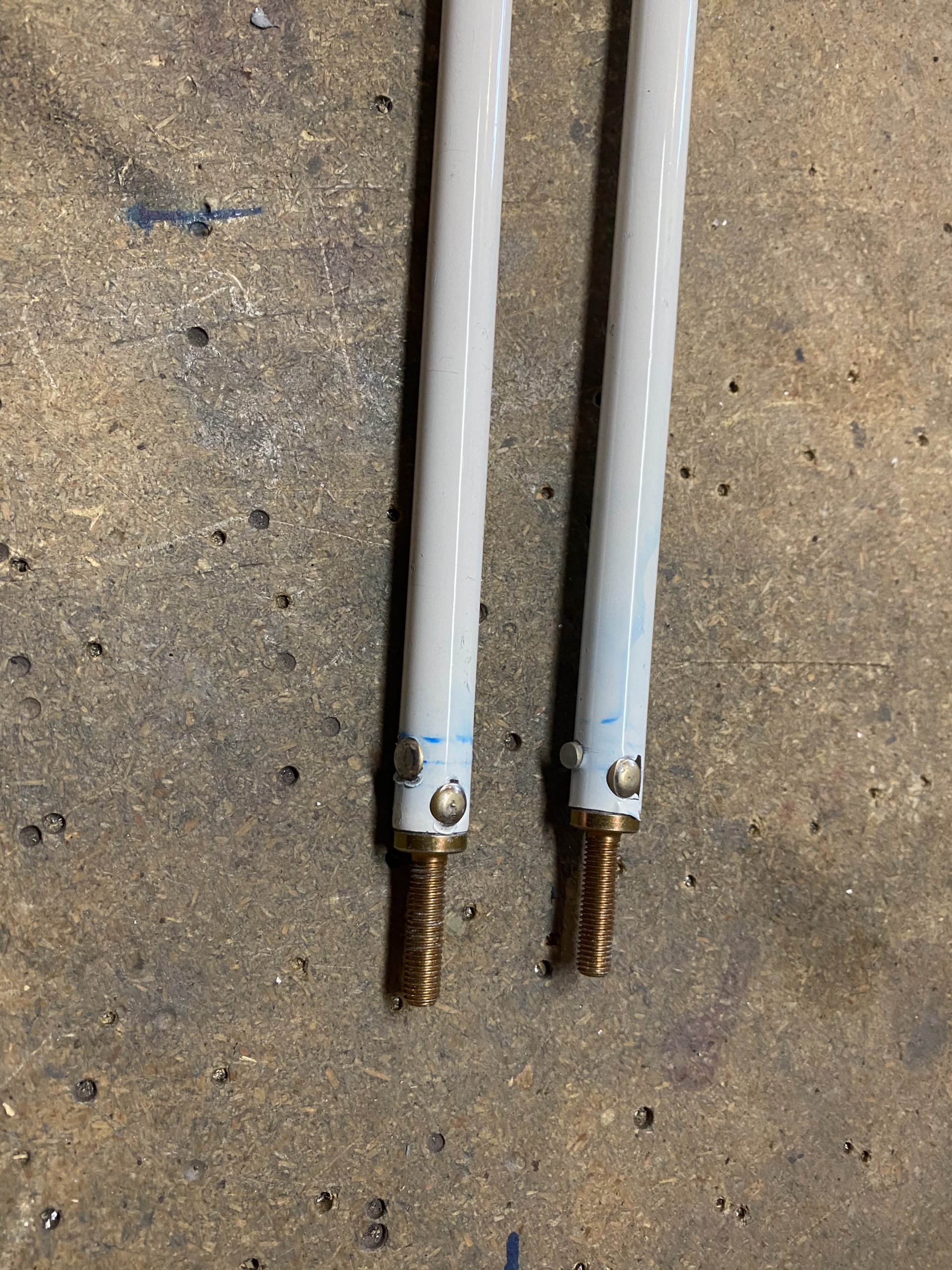
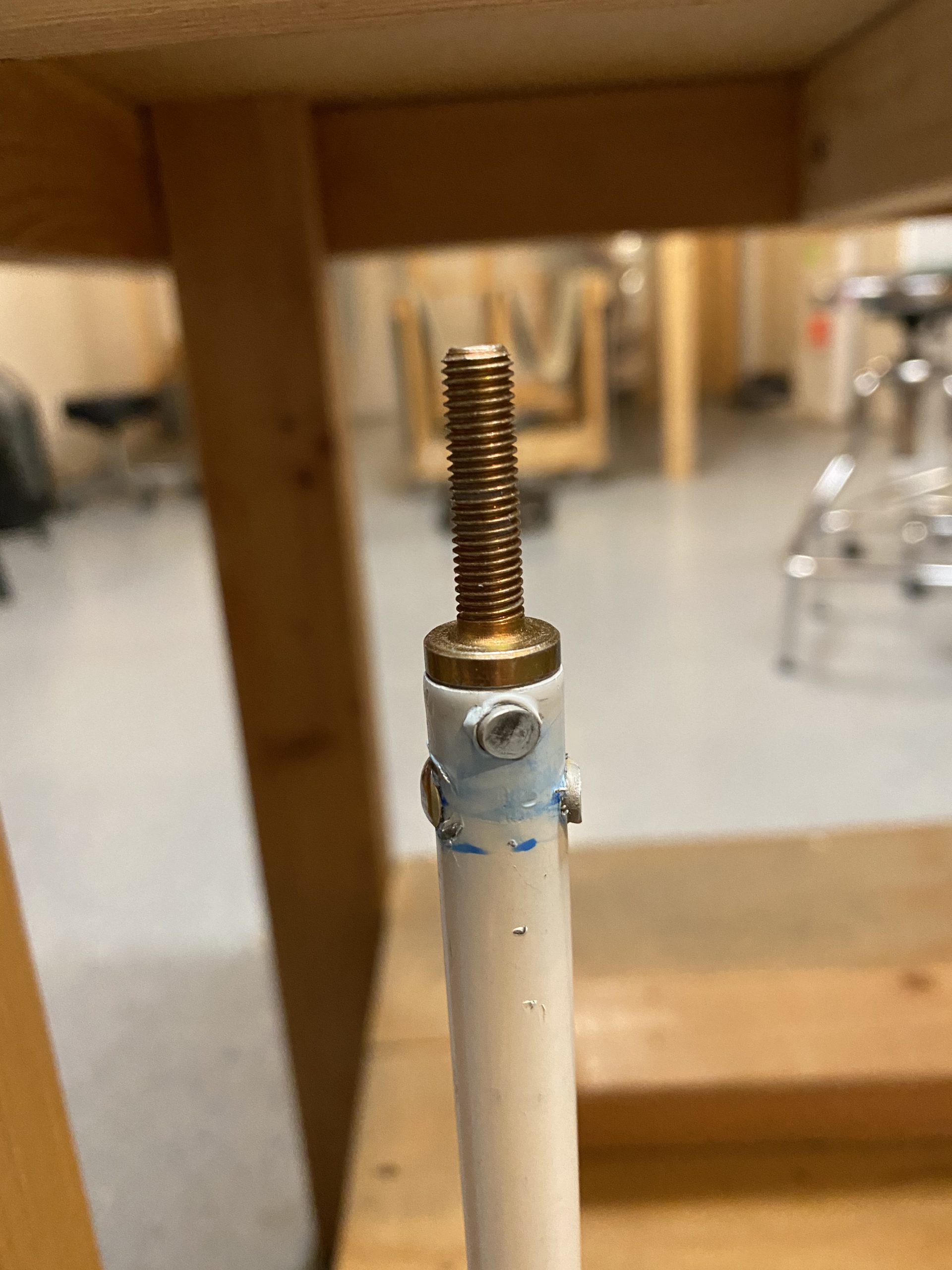
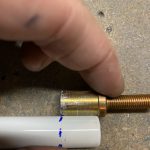
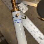
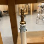
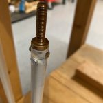
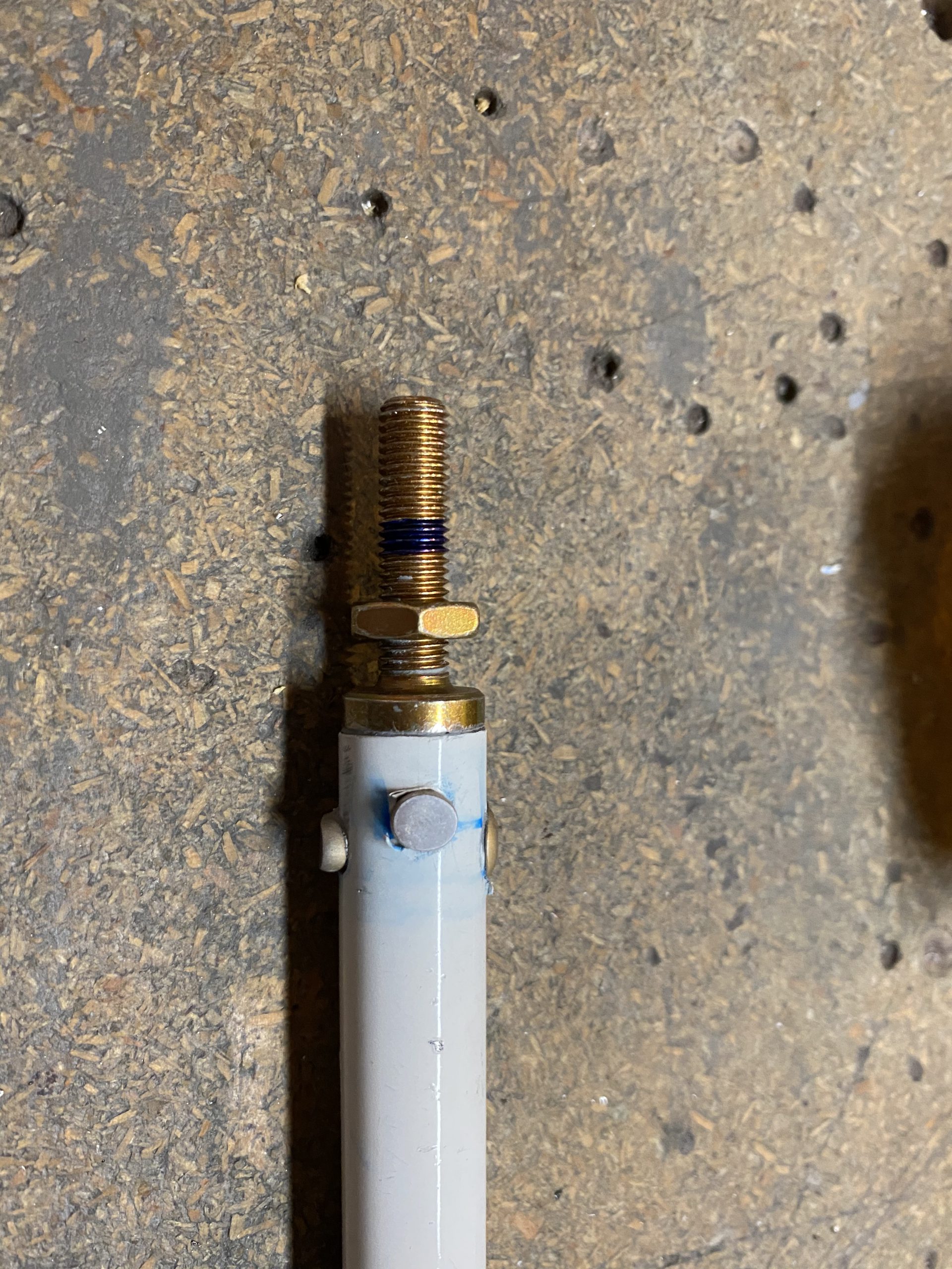
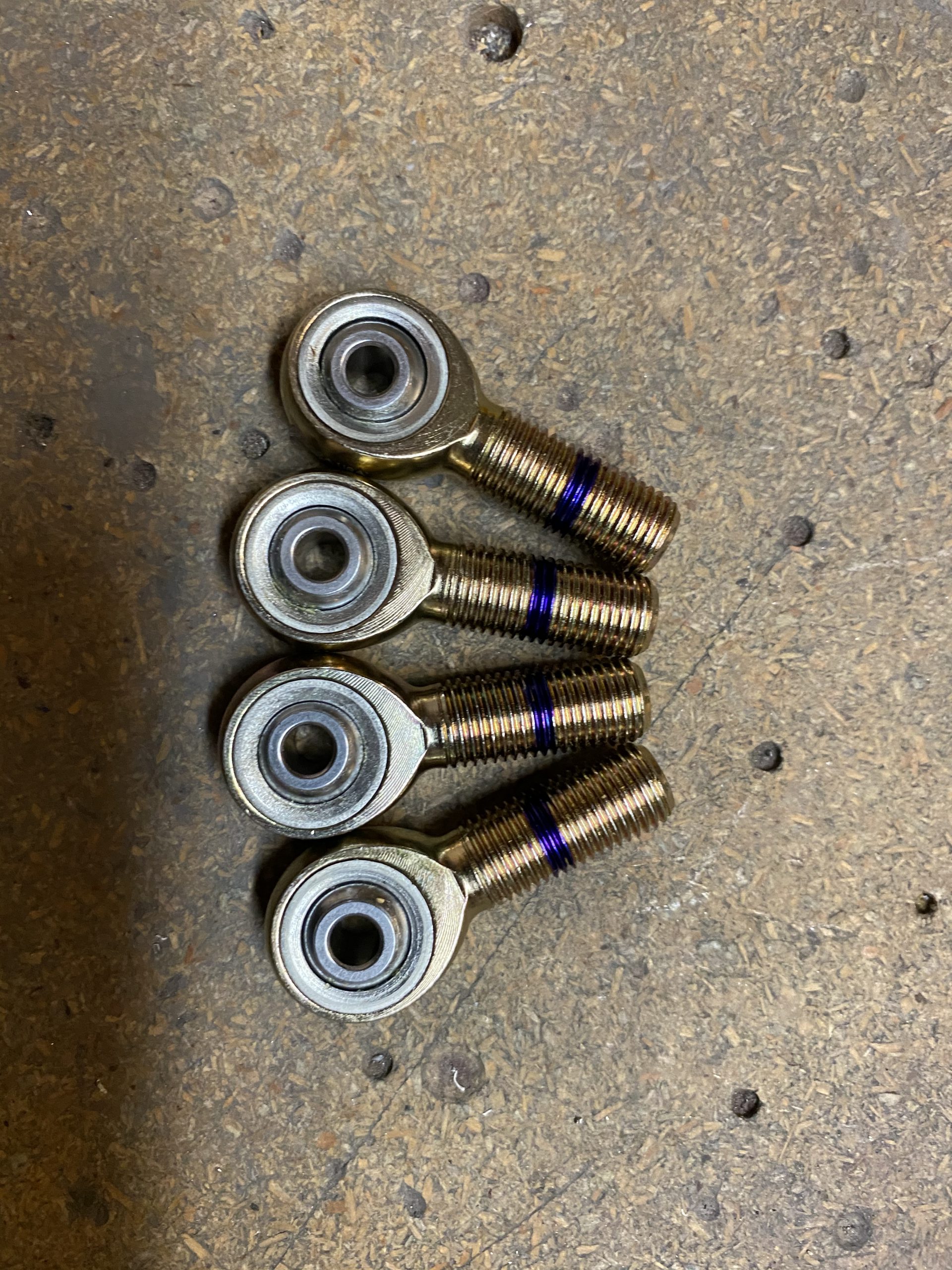
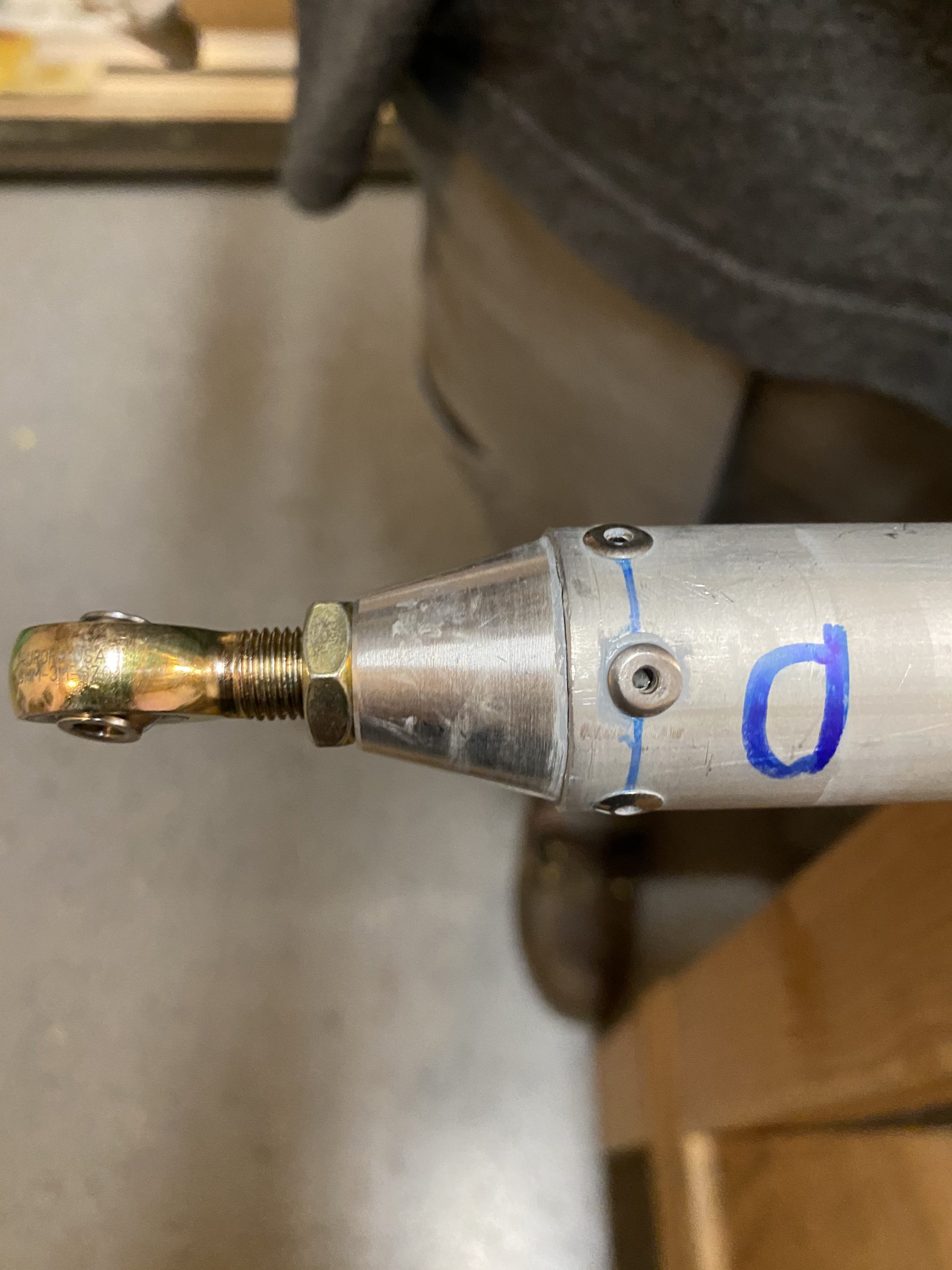
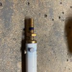
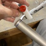
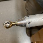
Once I had that done, I went ahead and threaded on the F341M heim joint, and the AN316-4 jam nuts on each end.  I marked a half-way mark on the threads of the insert with a blue sharpie so I’d know about where the halfway mark was when threading the heim joints on.

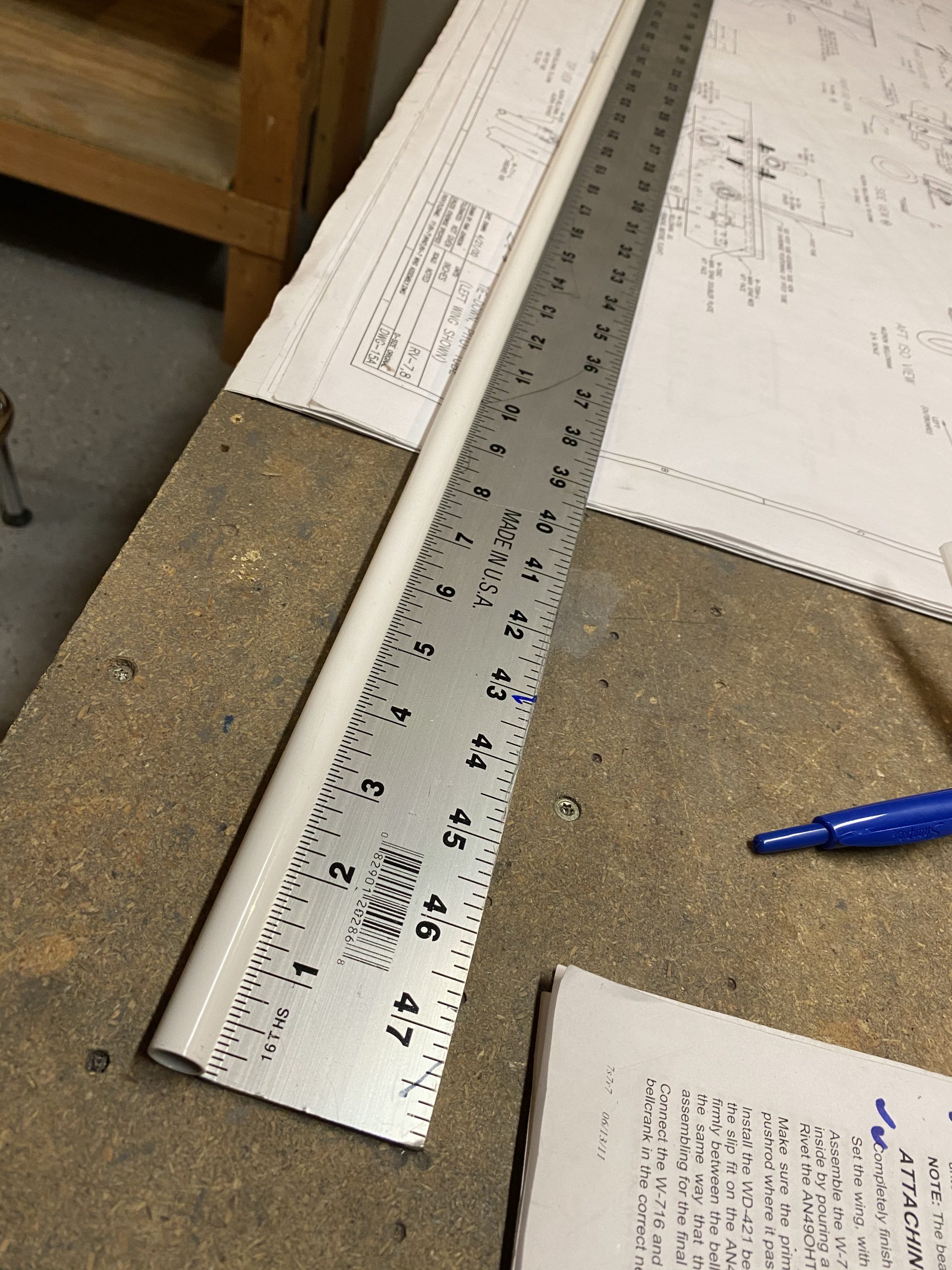
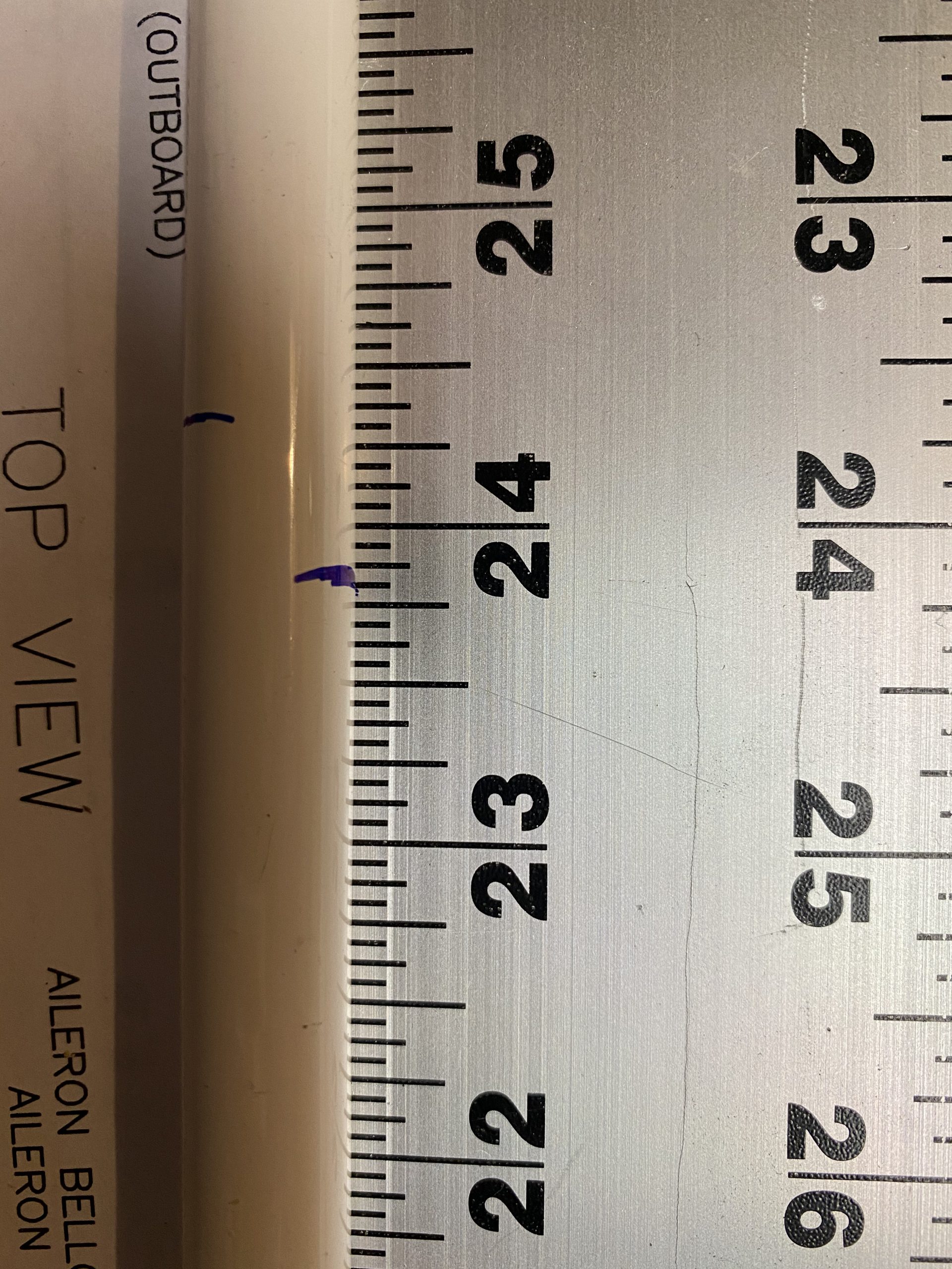
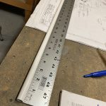
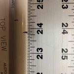
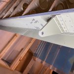
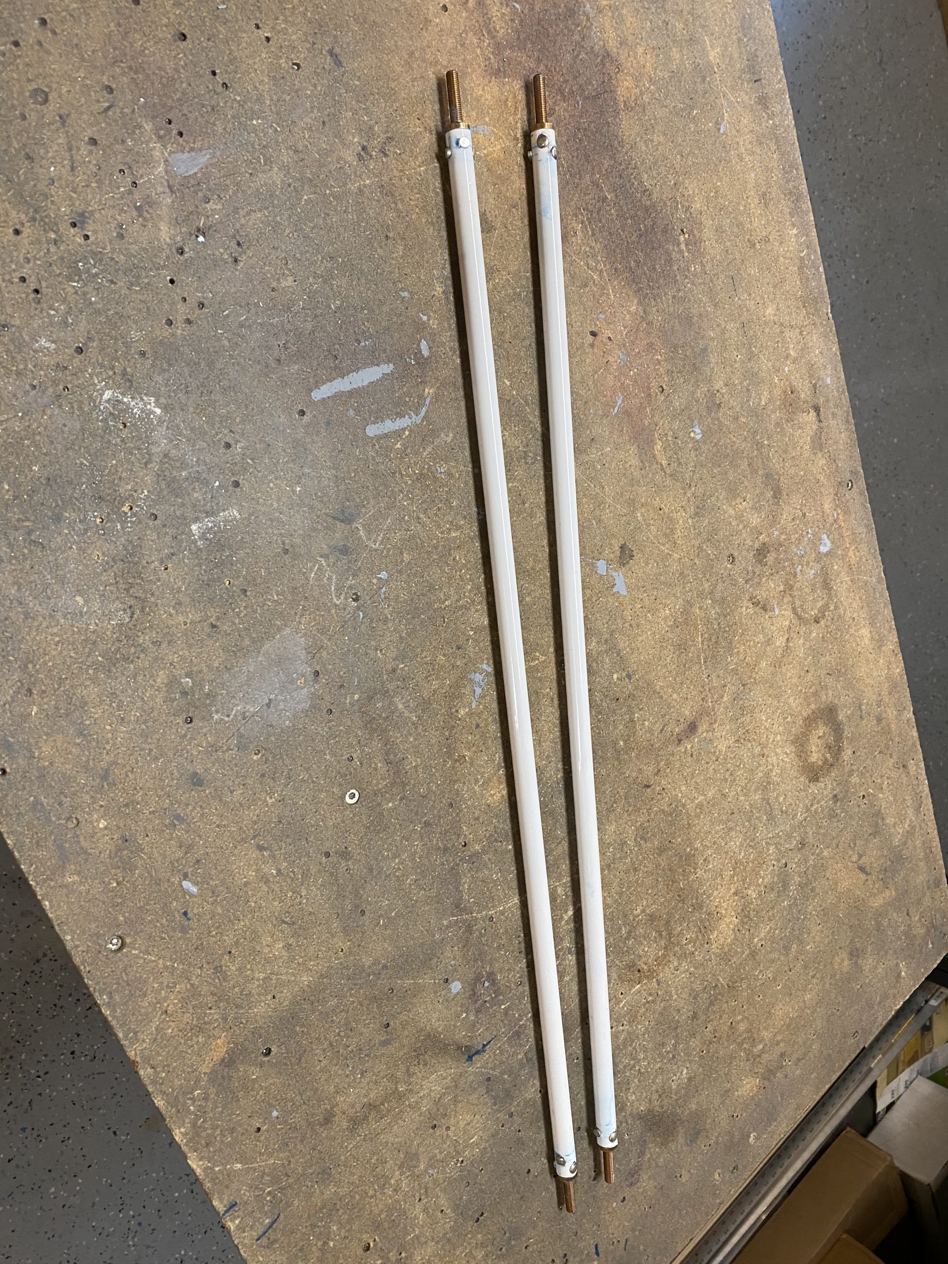
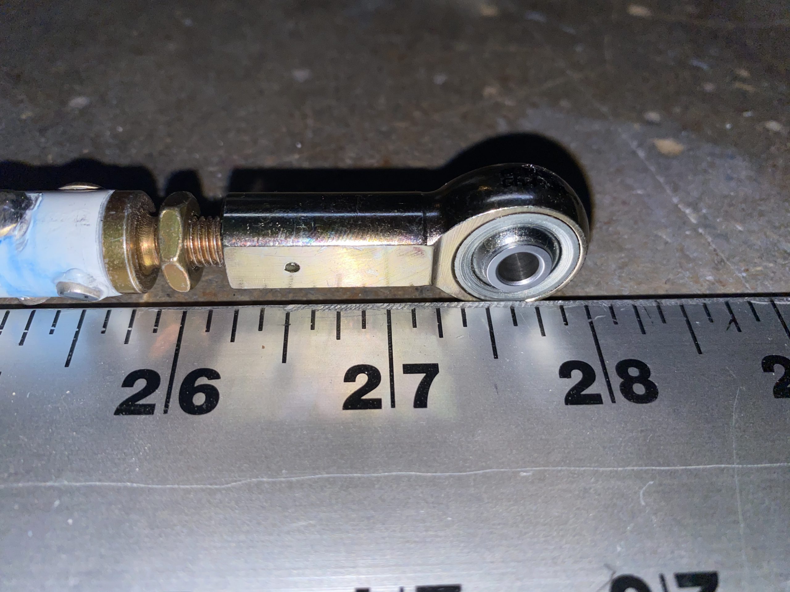
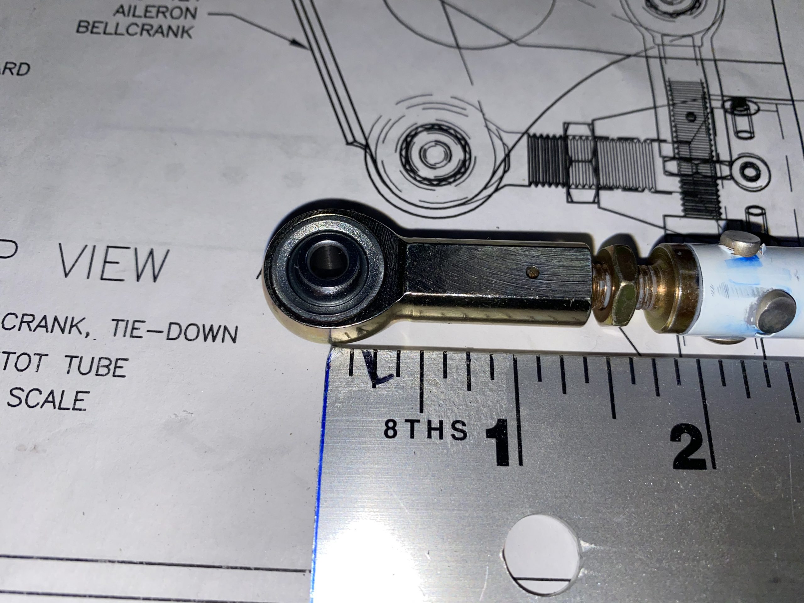
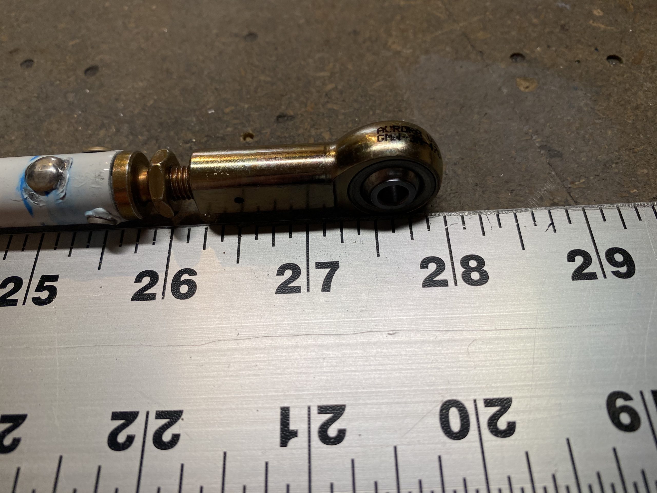
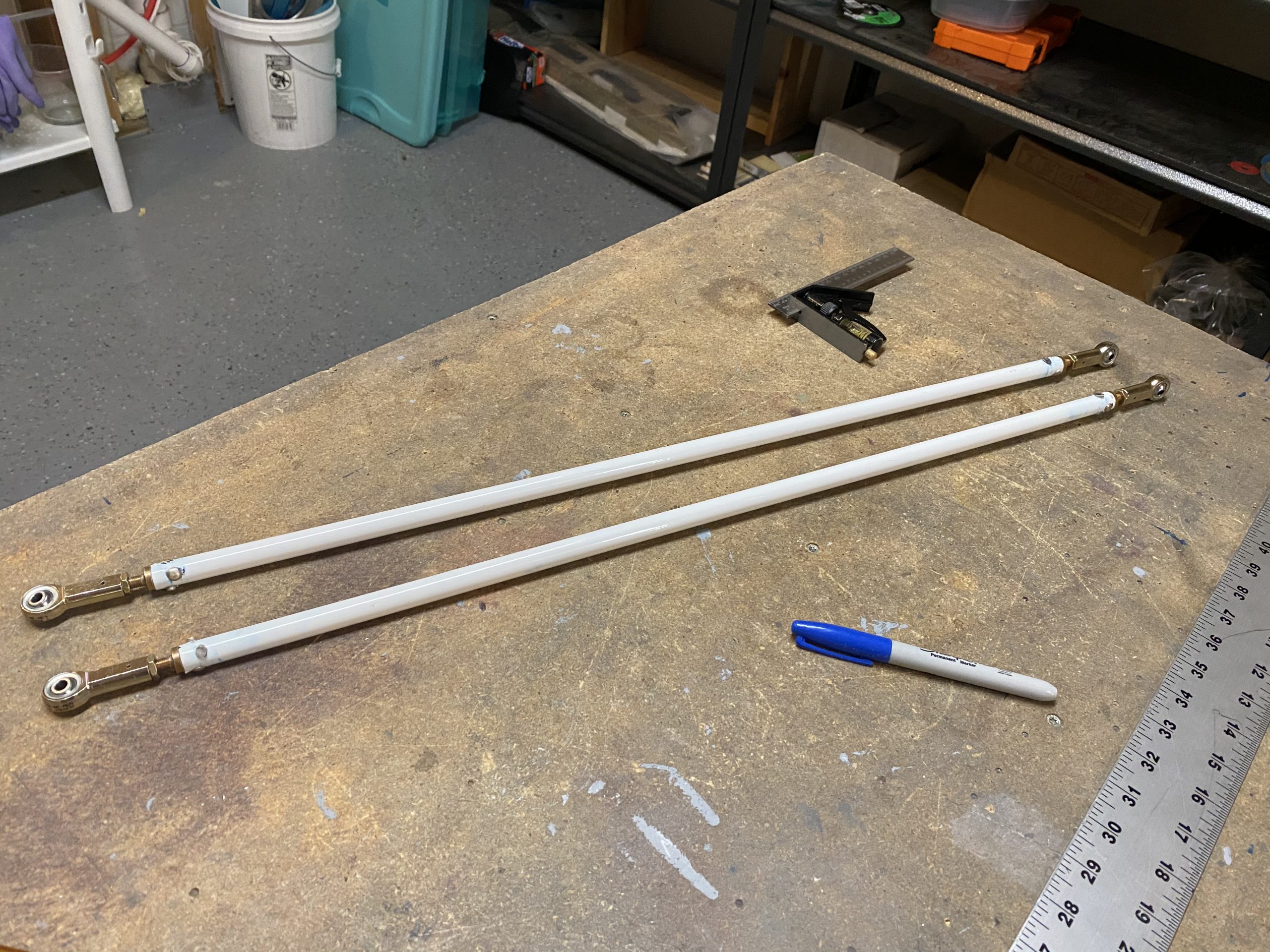
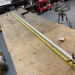
Then I used my 48″ steel ruler to adjust the heim joints on each end equally, until I had the proper 27 58″ of distance from the center of each bolt hole.  Then I torqued the jam nut down to hold them in place.  I did this for both of the pushrods.

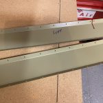
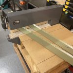
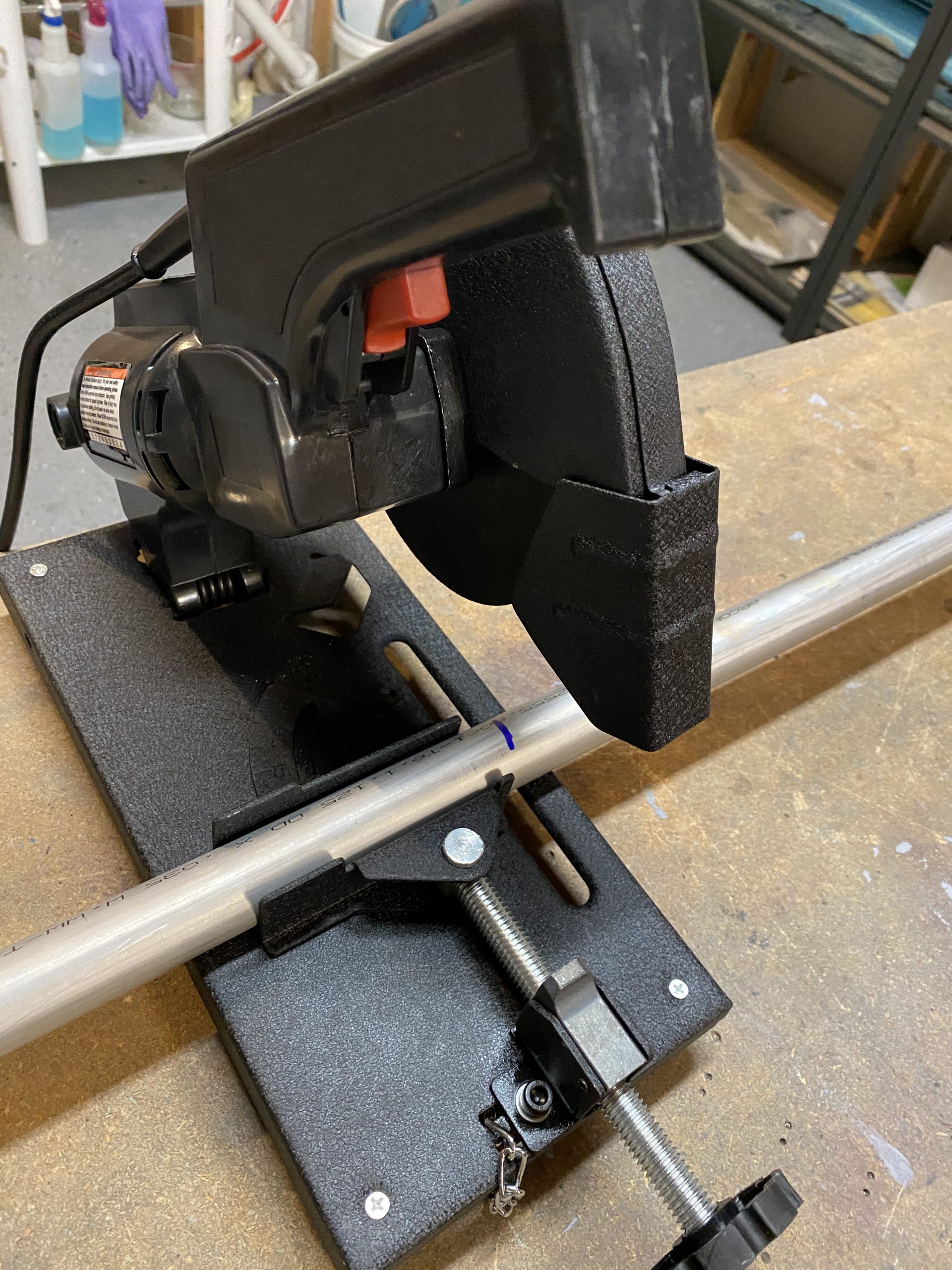
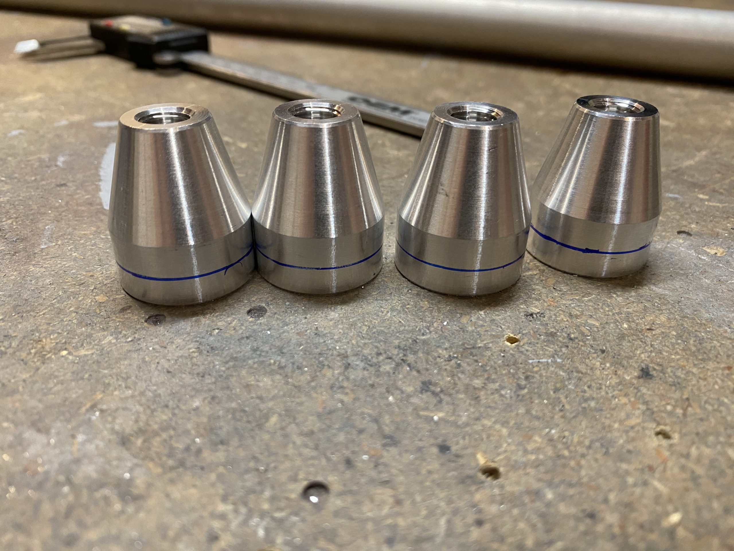
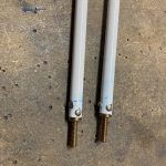
These are done! I’ll probably paint some primer on the riveted portion as it got a bit scratched up from riveting.  Next up was to make the W-717 push-pull tubes.  I pulled the AT5-035×1.125 stock tube, and decided to cut it in half.  Its exactly 12 feet long that would give me plenty of working room for each tube since this stock is only used for these control rods.  I used the little cut off saw to make this initial cut.

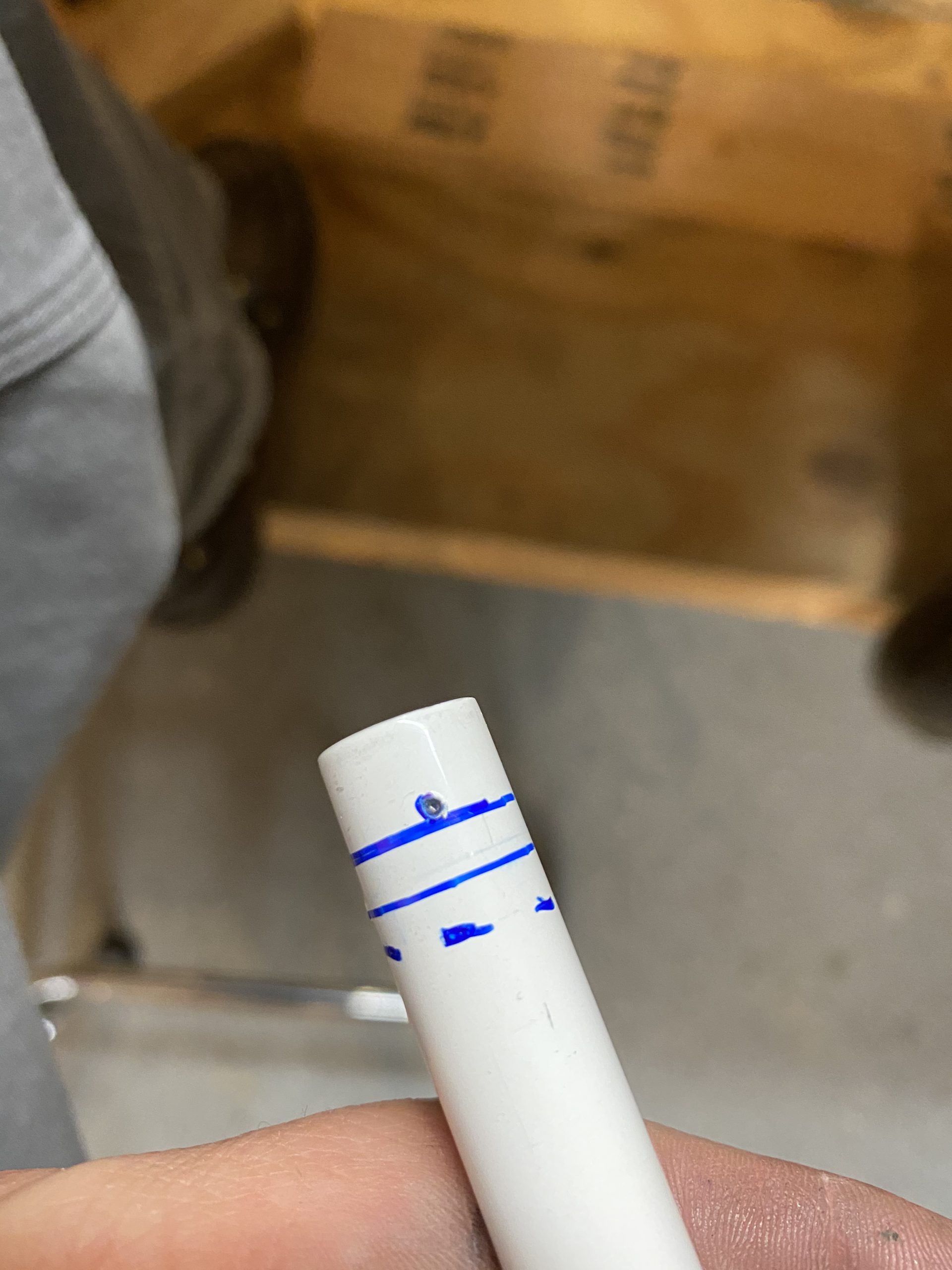
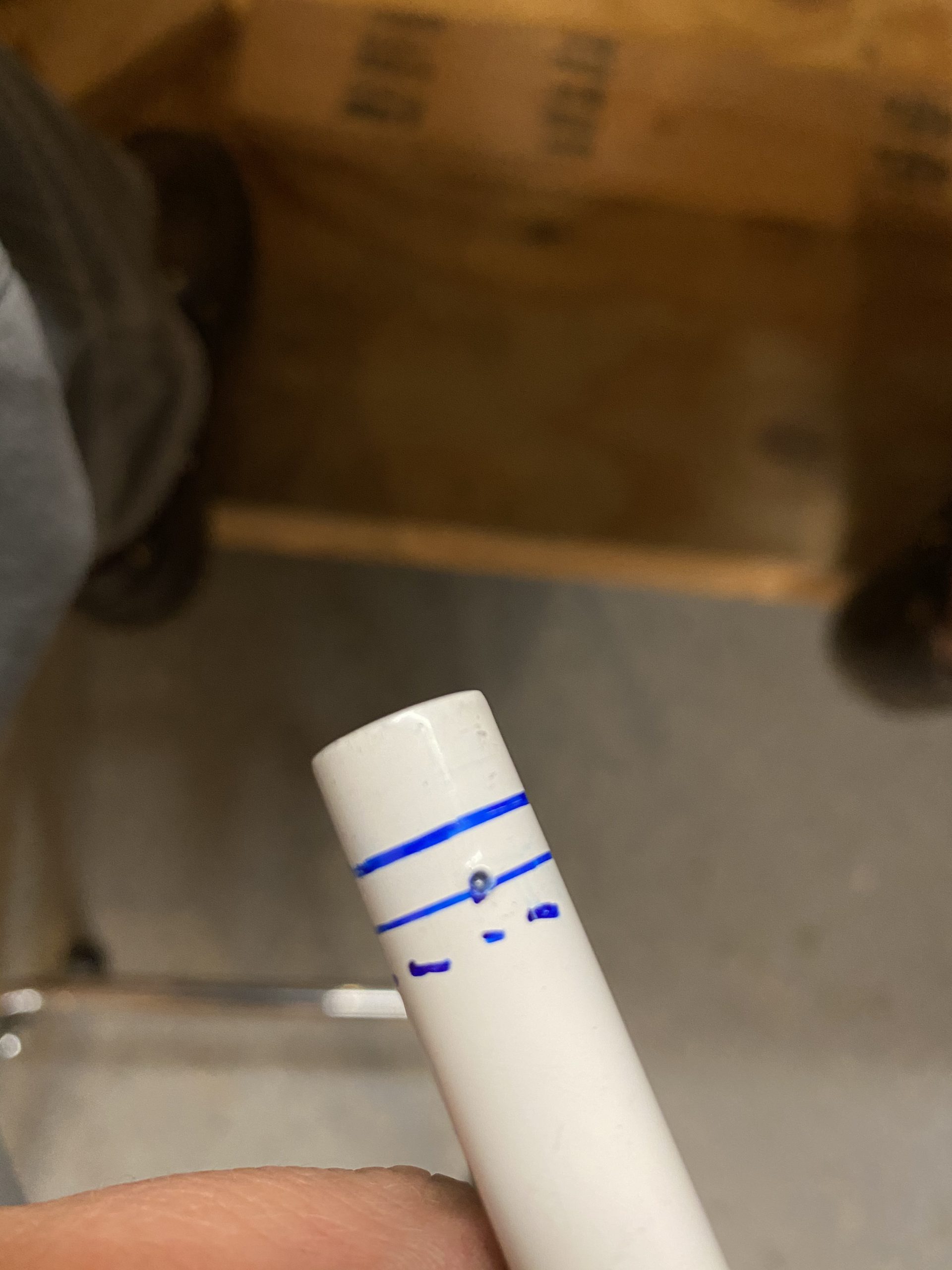
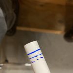
Next up was to rivet the VA-111 rod ends into the tube.  So I measured the shoulder of the VA-111 to be .5″, and decided to mark a line halfway, at 1/4″ to give me plenty of clearance.  I used the avery marking tool to make this easy, after I measured where 1/4″ would be.

Next, I wanted to do the same distance on the end of the tube itself, to guarantee plenty of edge distance.  So, I measured 1/4″ and used the avery tool to make a line around the tube.  In theory, the line from the VA-111 and the tube should be in alignment, and give me plenty of distance when drilling the holes.

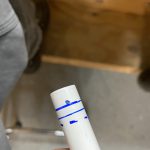
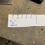
Now, its time to drill.  I used a piece of paper, marked out spacing of 19/32″ spacing and wrapped around my tube as a guide.

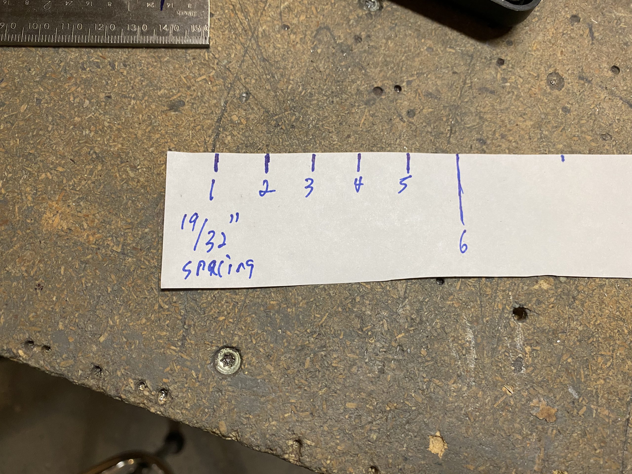
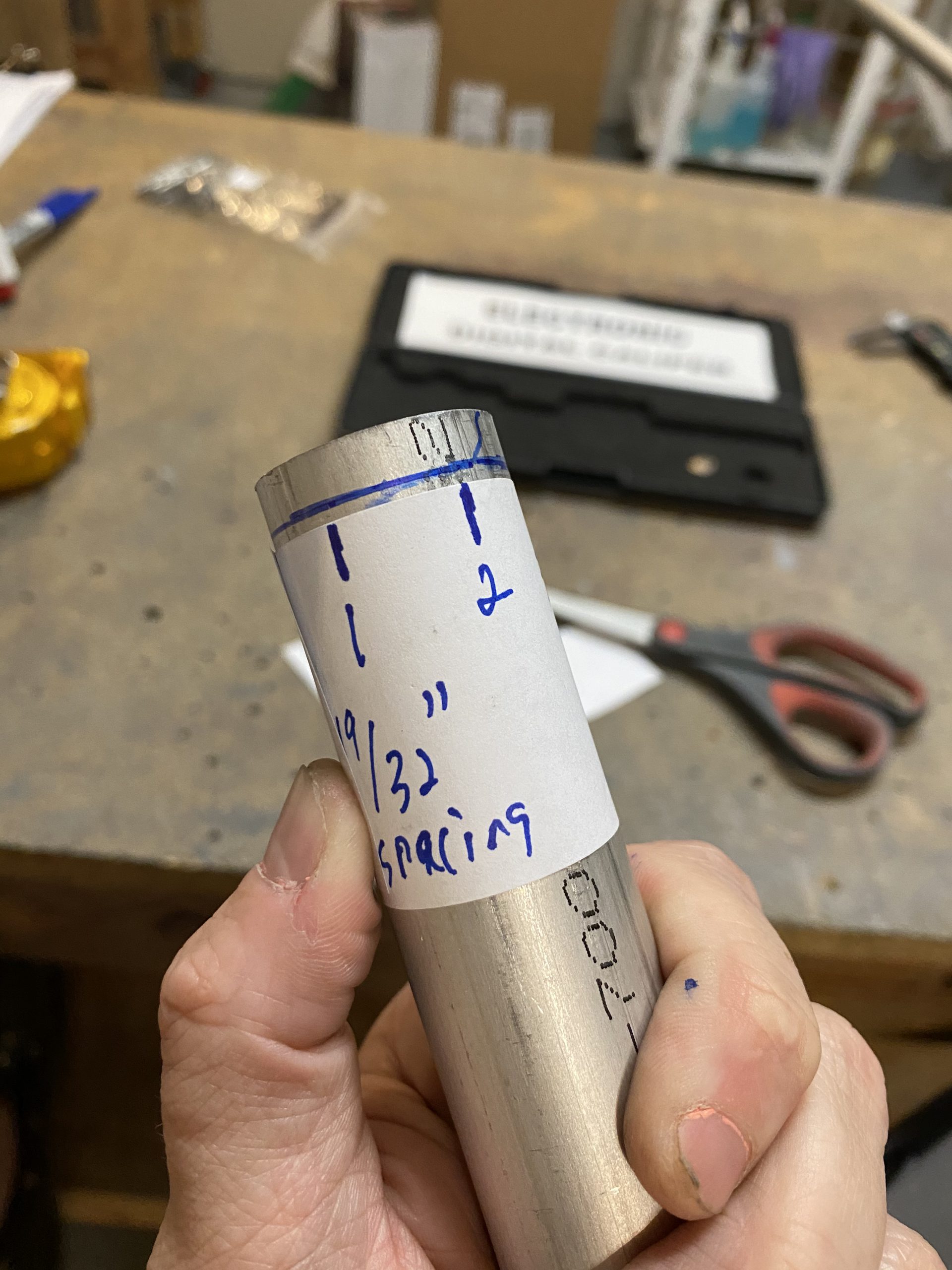
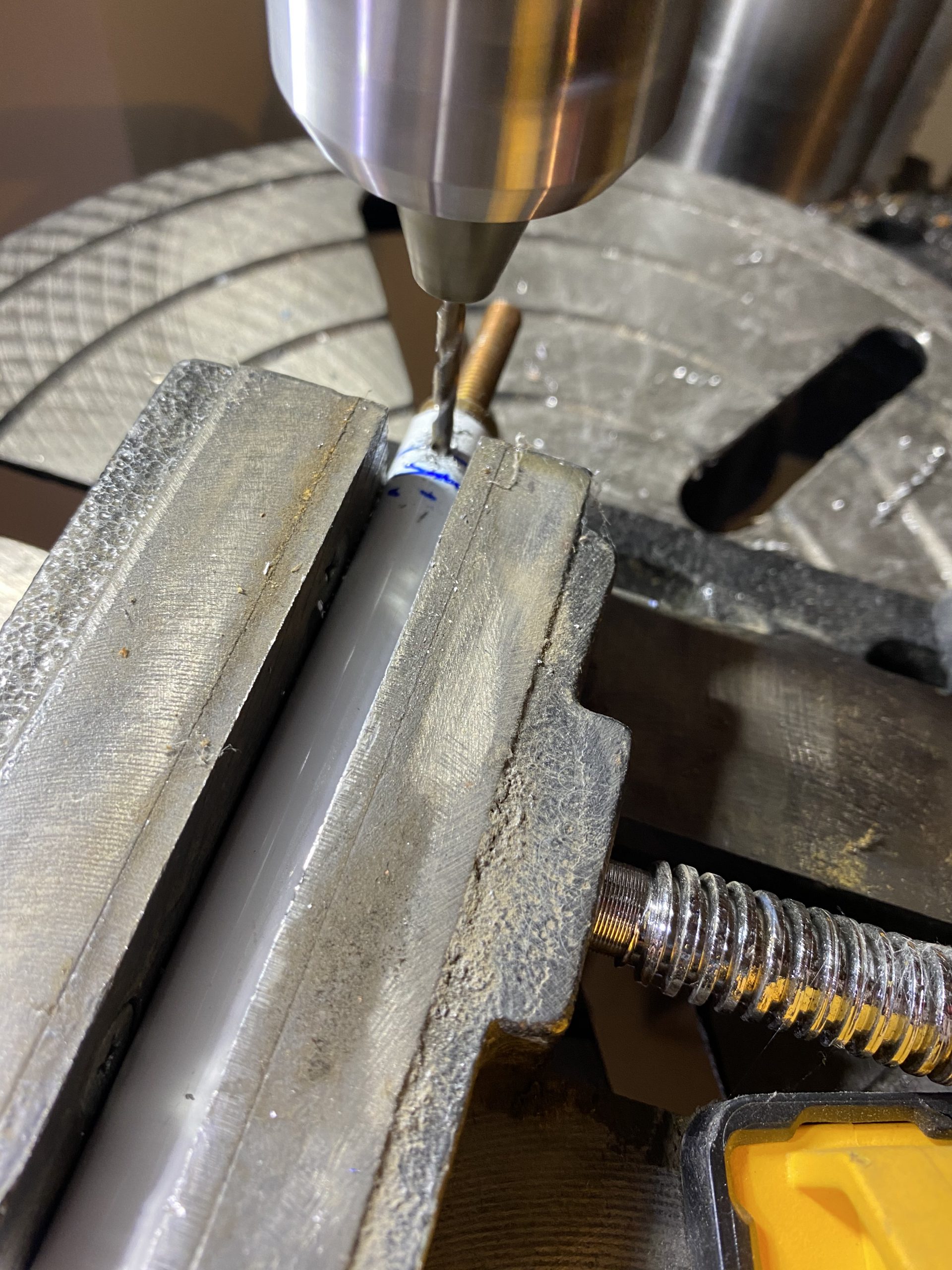
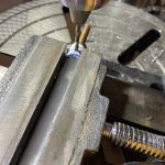
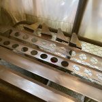
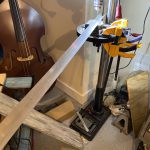
I marked the lines of where to drill for the rivet holes using that paper template, and my 1/4″ line. This give me 6 evenly spaced rivet holes, with 1/4″ of distance.  Should work perfectly!  I made a simple drill jig, using some scrap angle aluminum in a drill press vise.  Then centered up the drill bit into the “V” of this jig to help me make sure I get the bit centered on my tube.

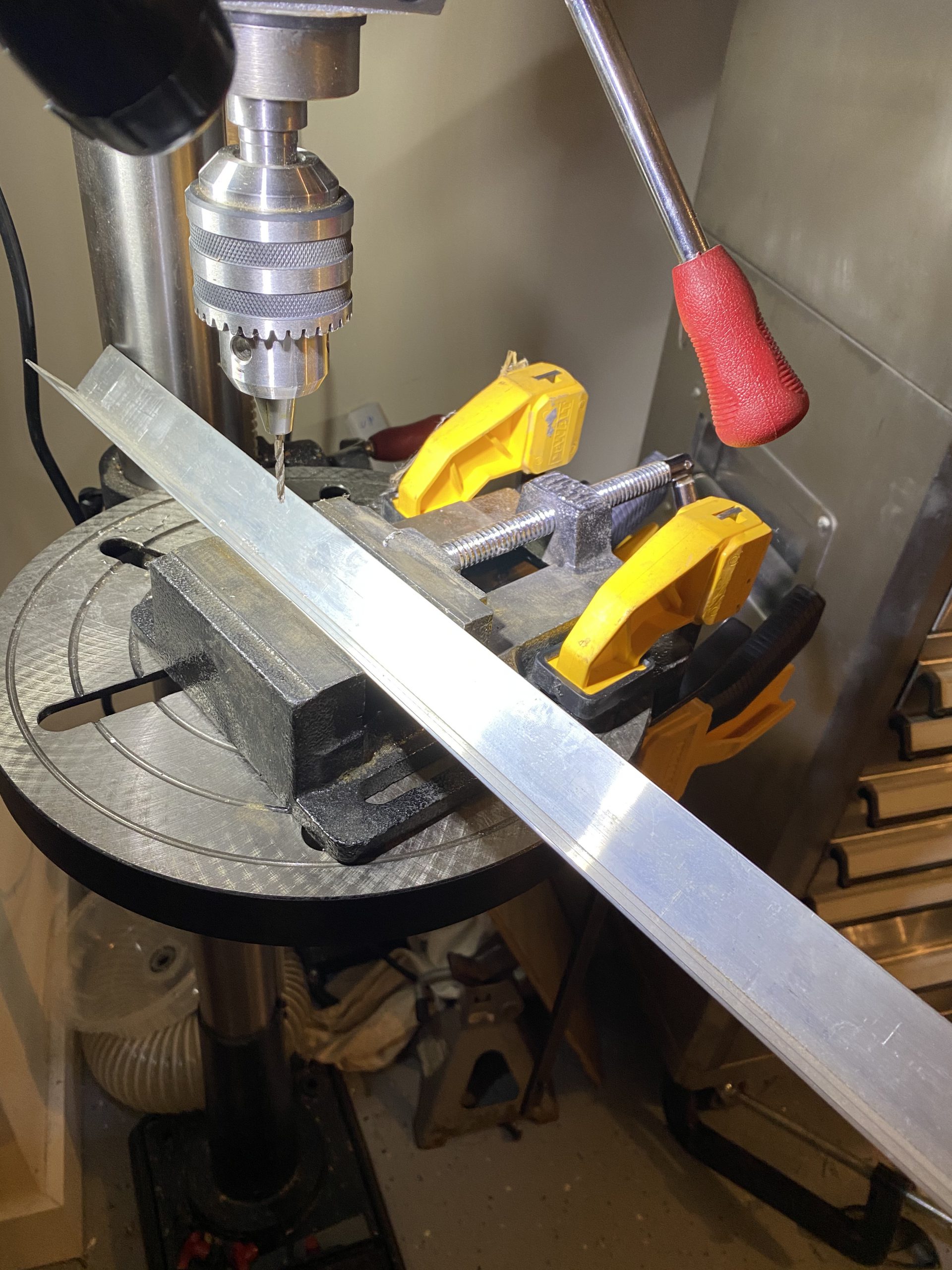
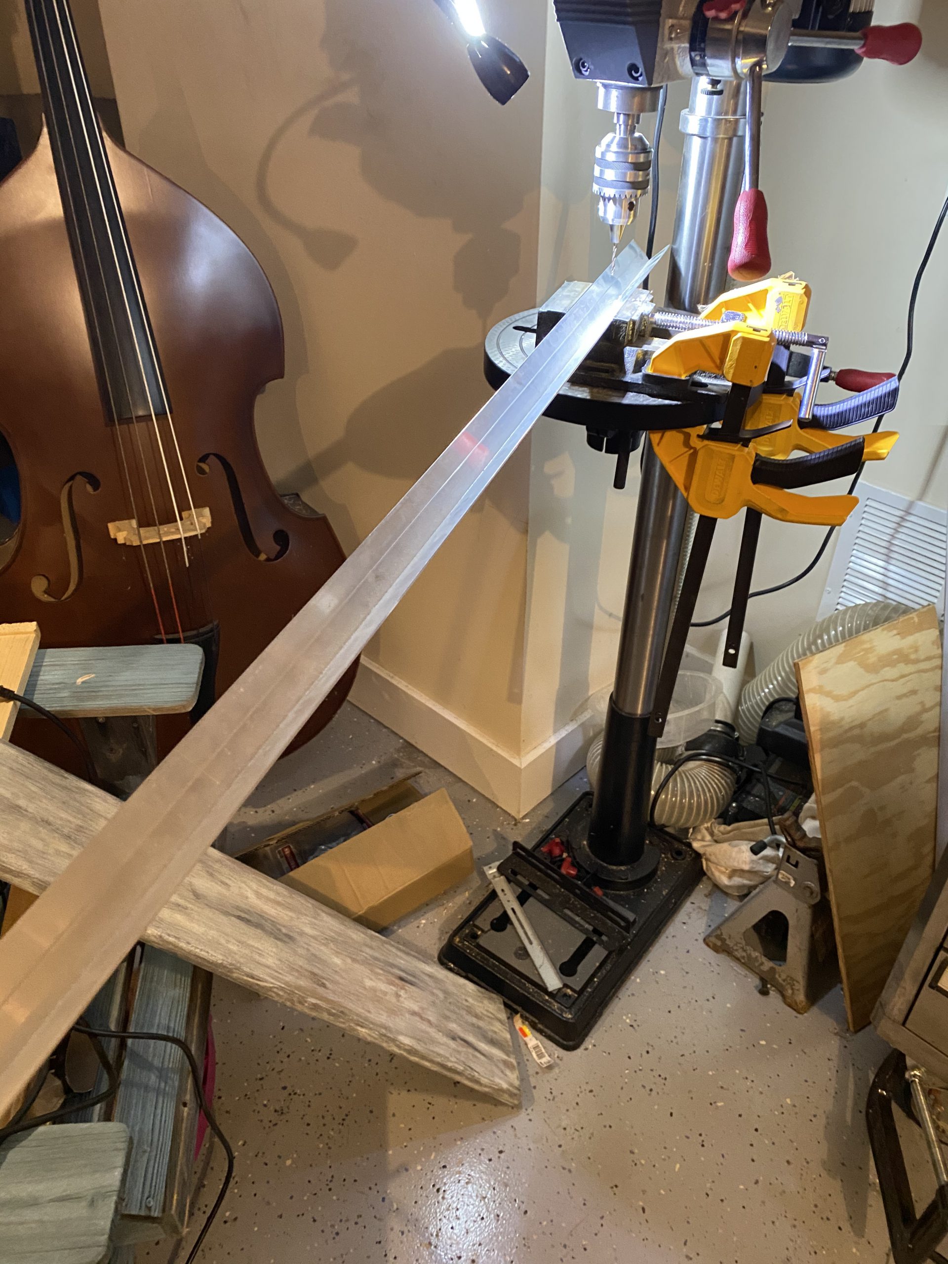
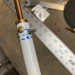
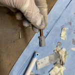
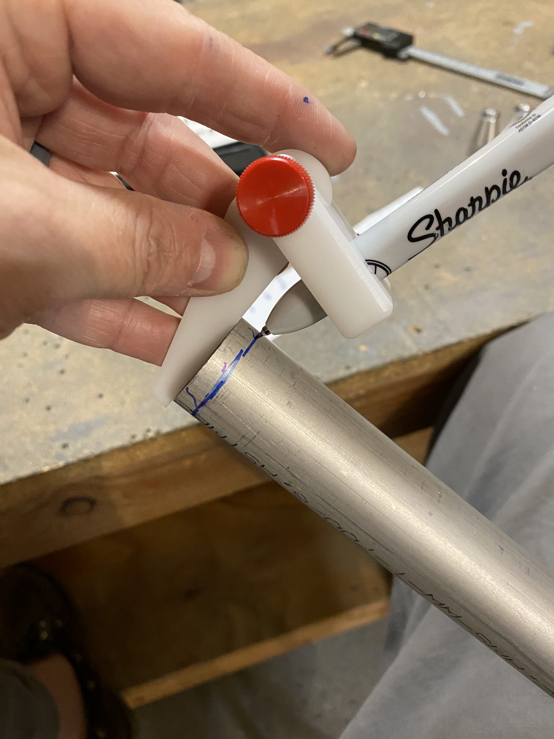
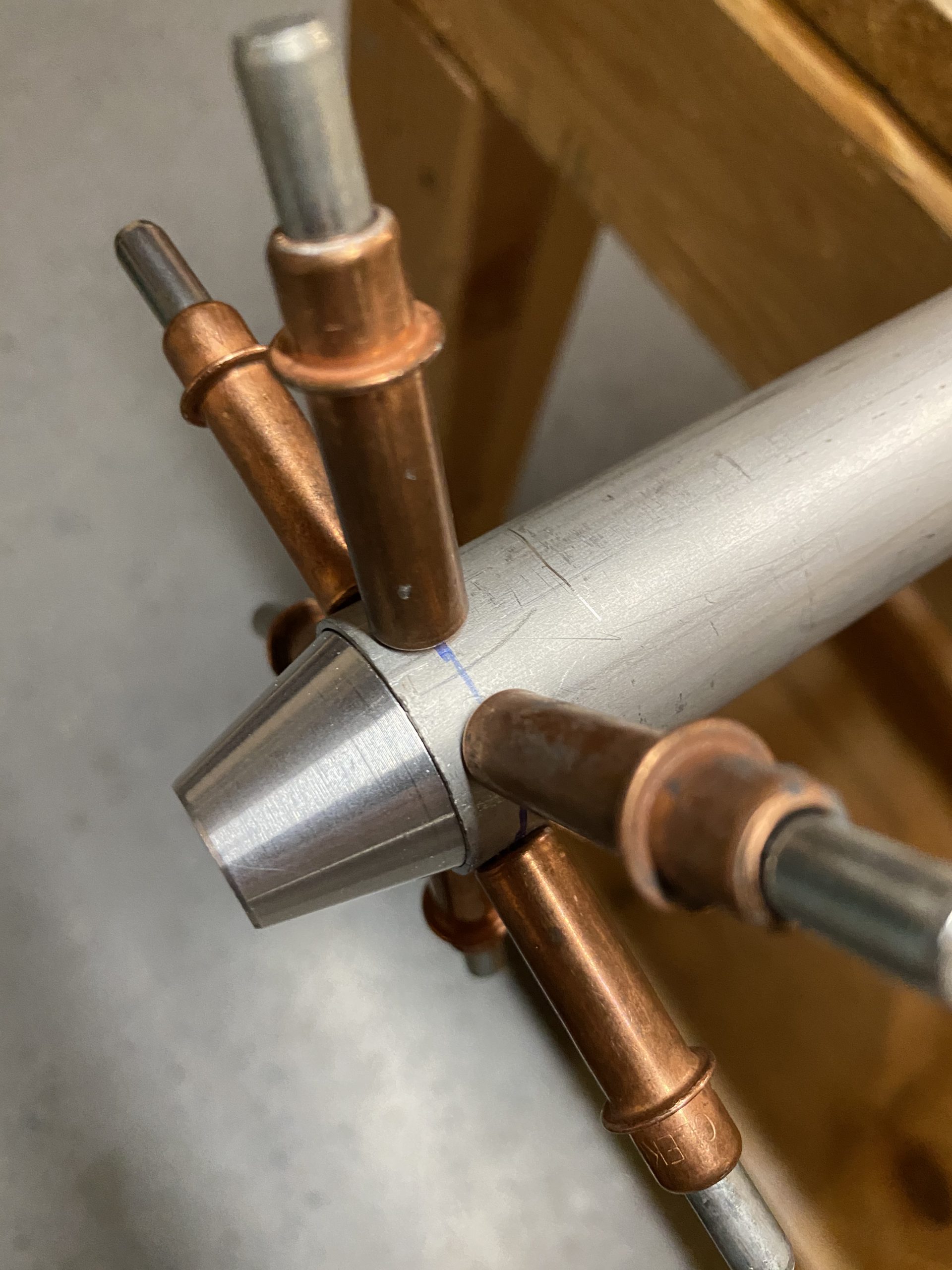
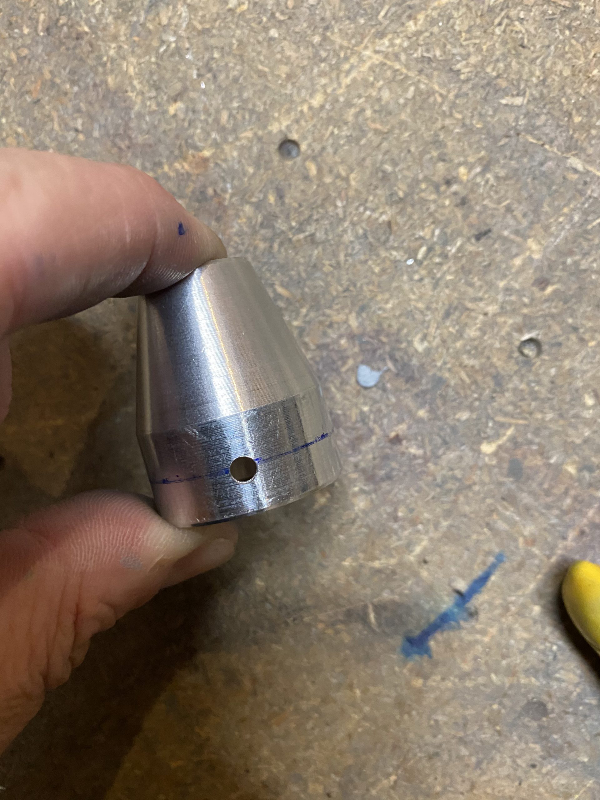
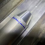
Then clamped the jig down, and laid my tube in the jig, without the VA-111 inserted.  I drilled a single hole in the tube first, then I will use this hole as a sighting hole to line up the blue sharpie line I made on the VA-111 to make sure its lined up and inserted to the proper depth.

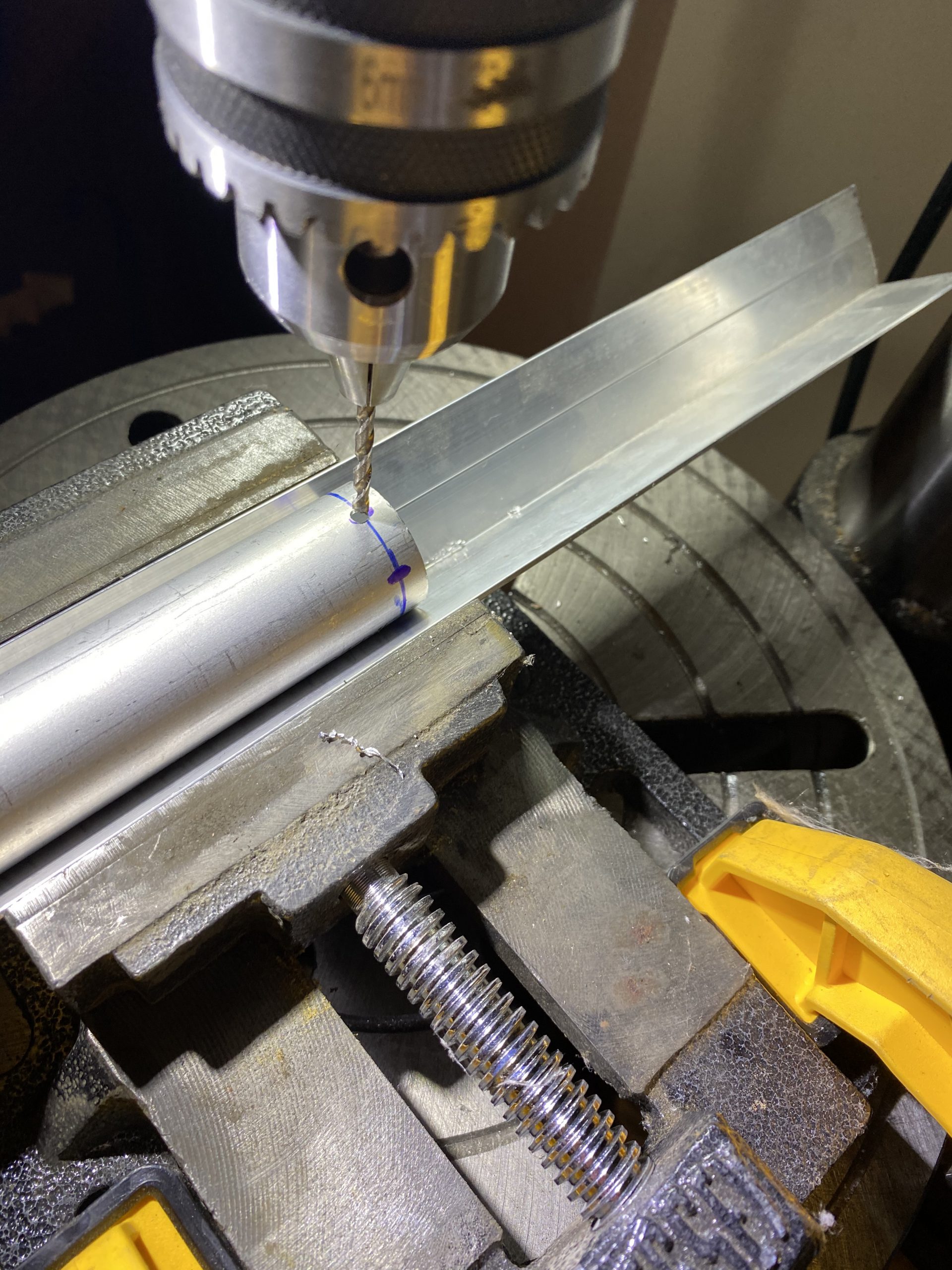
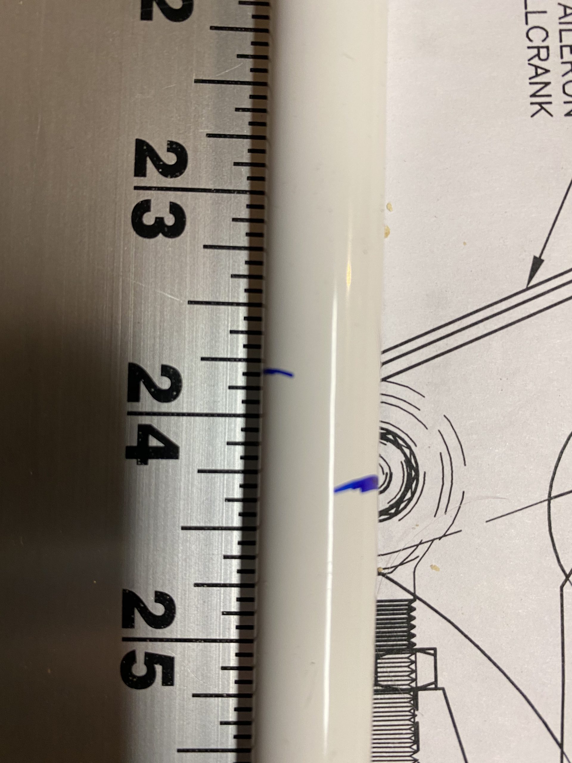
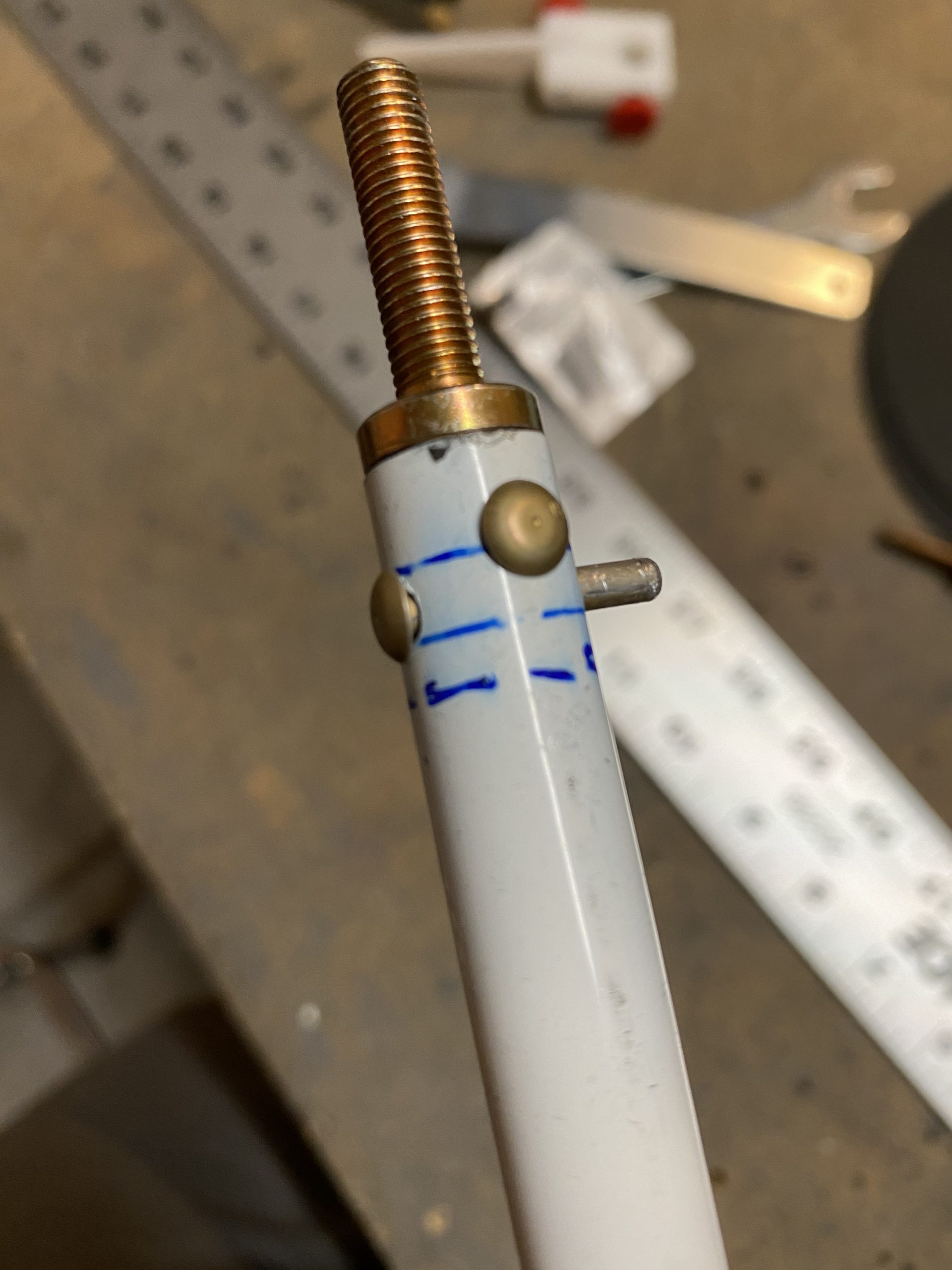
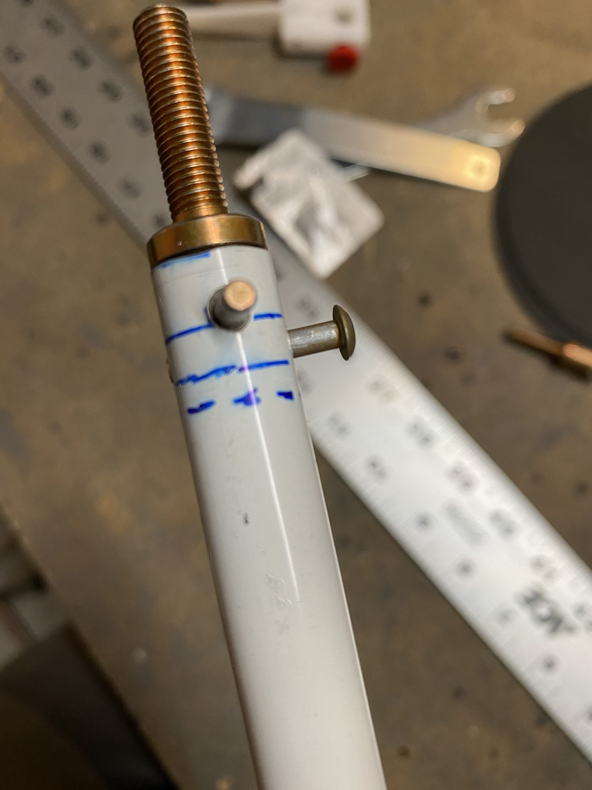
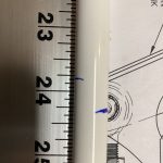
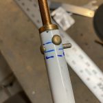
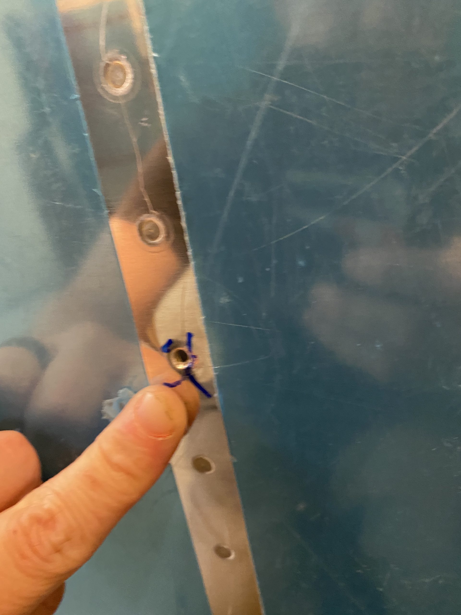
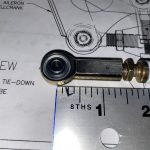
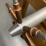
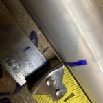
Now that the hole is drilled into the tube, I inserted the VA-111 and lined up the 1/4″ index line in the center of the tubes hole, and then used this to back drill the first hole into the VA-111. You can see the blue line on the VA-111 insert through that new hole in the tube in the photo below.

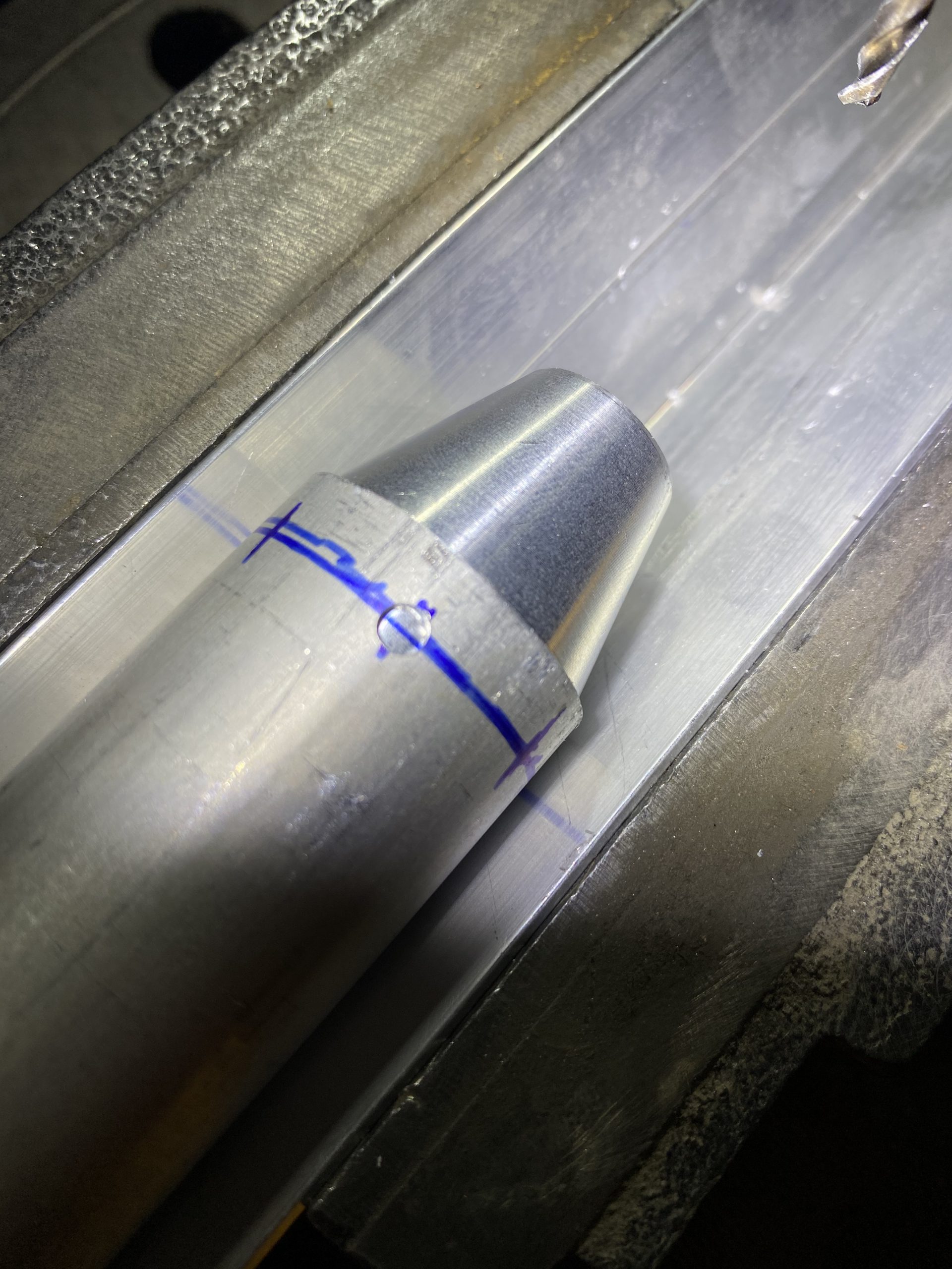
I gently put this lined up assembly under the drill bit, and drilled the hole into the VA-111.  This worked out PERFECTLY! It allowed me to drill the hole in the exact spot with no edge distance issues.

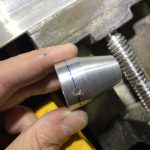
Next, I reinserted the VA-111 and clecoed it in place using this new hole.  This assured me that everything else would line up, and I could just drill the tube and the VA-111 at the same time.  I’d drill a new hole, insert a cleco and then drill the next hole, using my index marks.

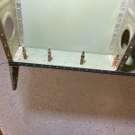
Eventually, I ended up with 6 very nicely spaced holes in the tube and VA-111.  I am pretty stoked about how this worked out.

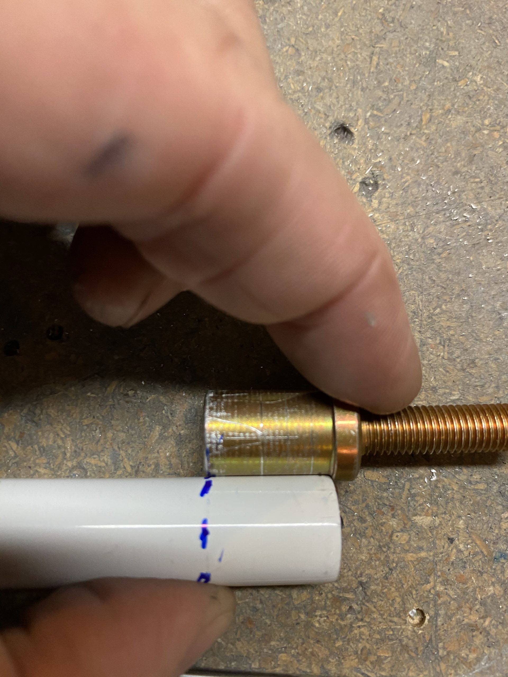
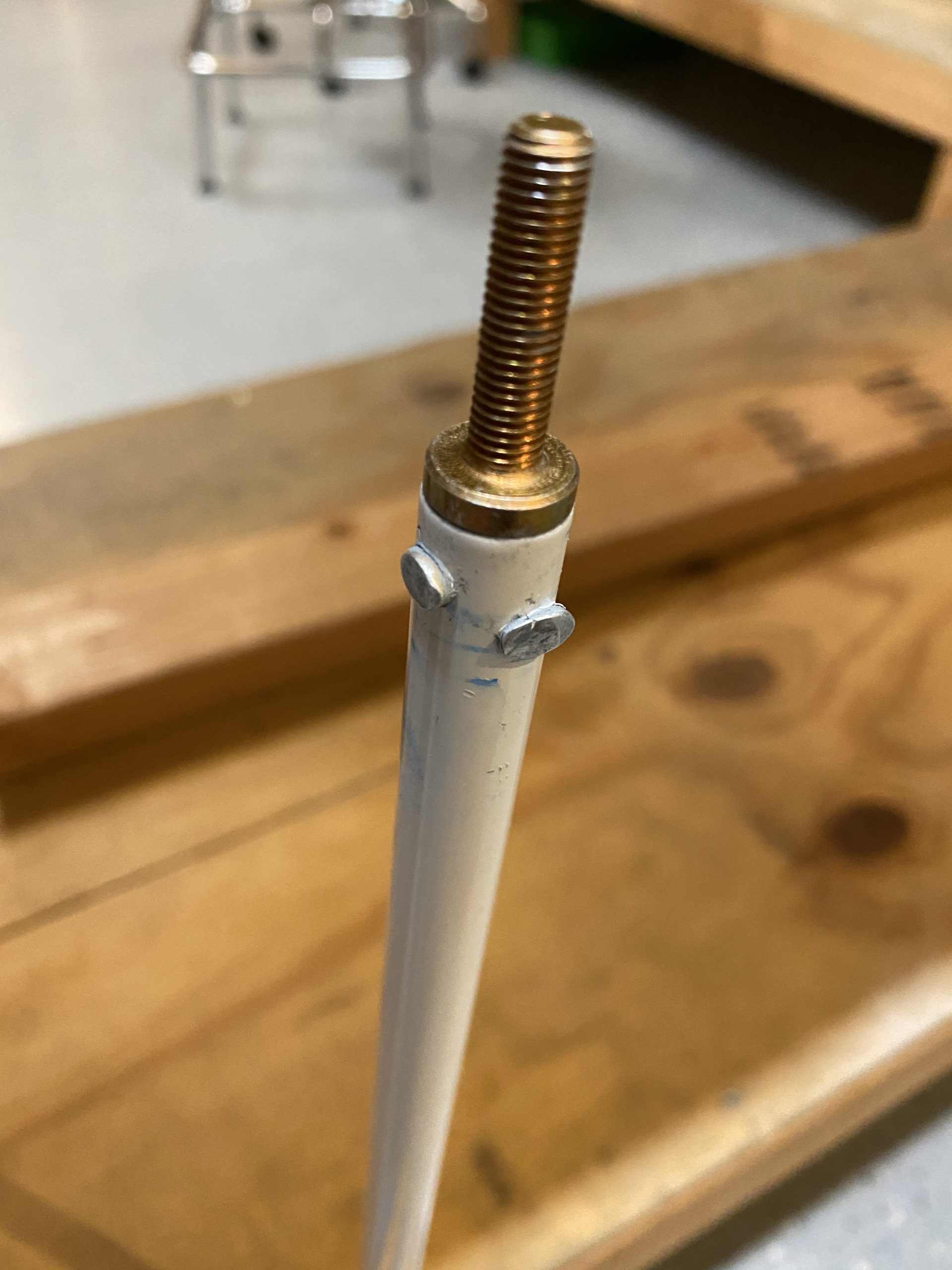
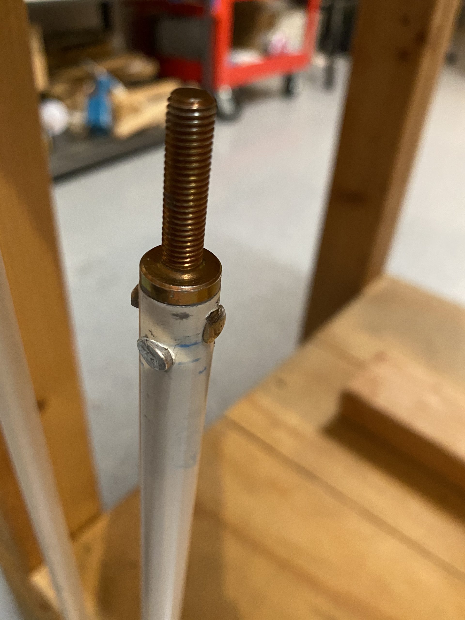
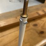
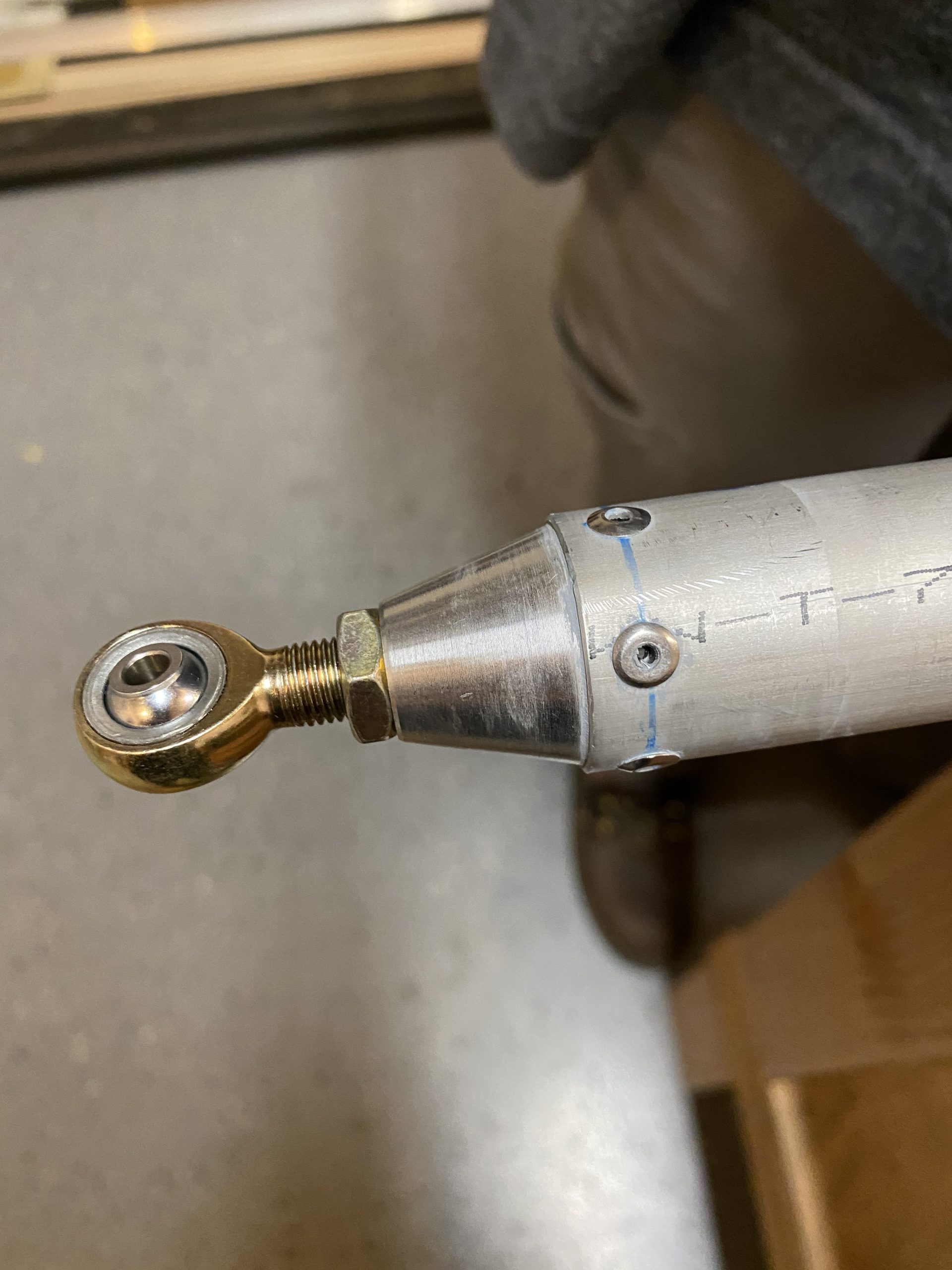
Now, I wanted to get one rod end done on each of the tubes to give me a place to start my measurements, which is important in the next steps.  So, I essentially did this same procedure on the second pushrod tube. Recall my tubes are 6 feet long, way longer than the plans calls for.  I have read the plans dimensions are a bit too short for the end measurement, leaving the threads of the rod end and heim joint out of spec and too far out to make up for the short tube length.  So, I marked the halfway point on the threads for the M3614M heim joint with a sharpie and threaded them into the rod end bearings. We only want to thread these heim joints to the halfway point to give us plenty to work with for adjustments later on.

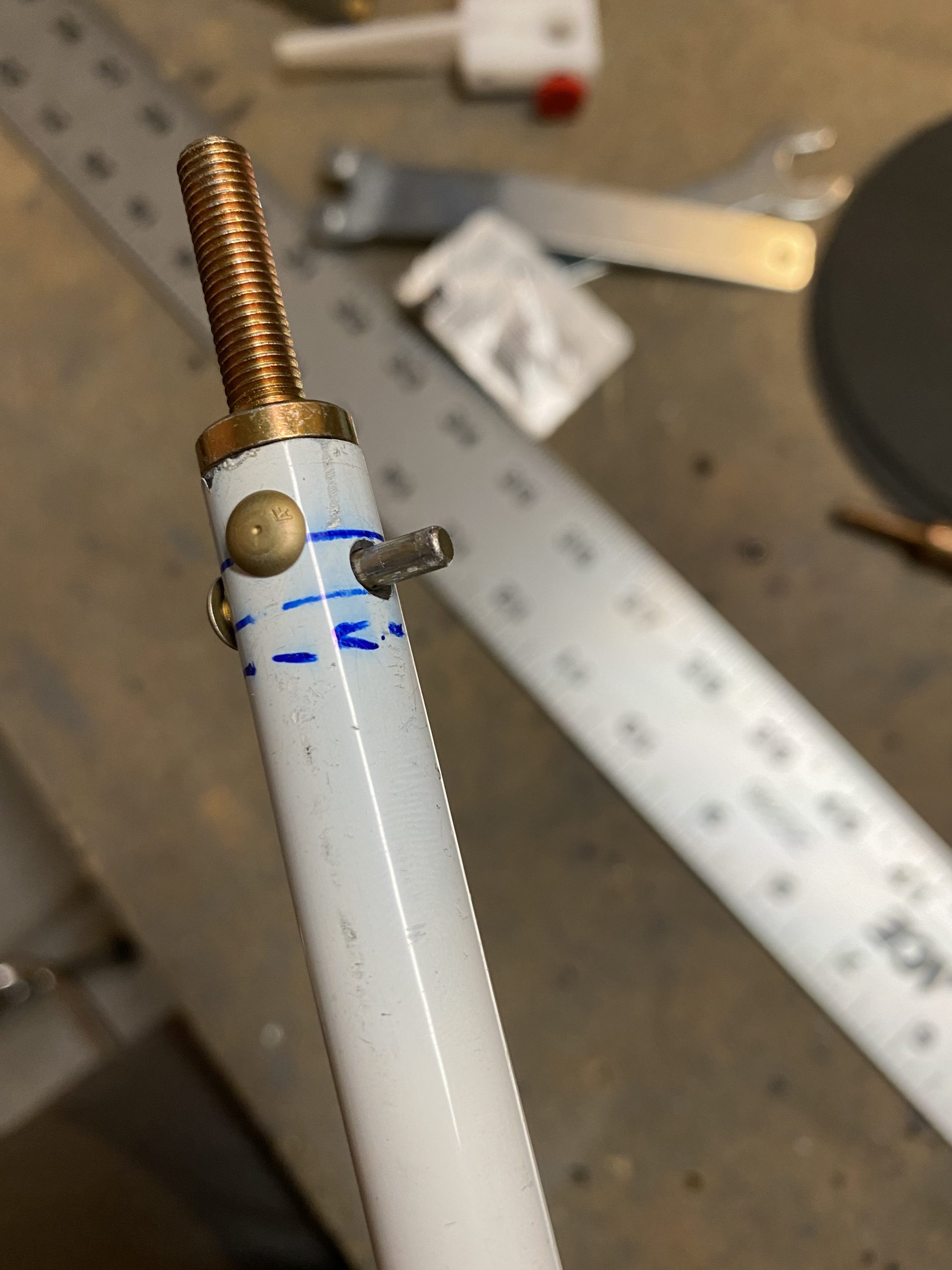
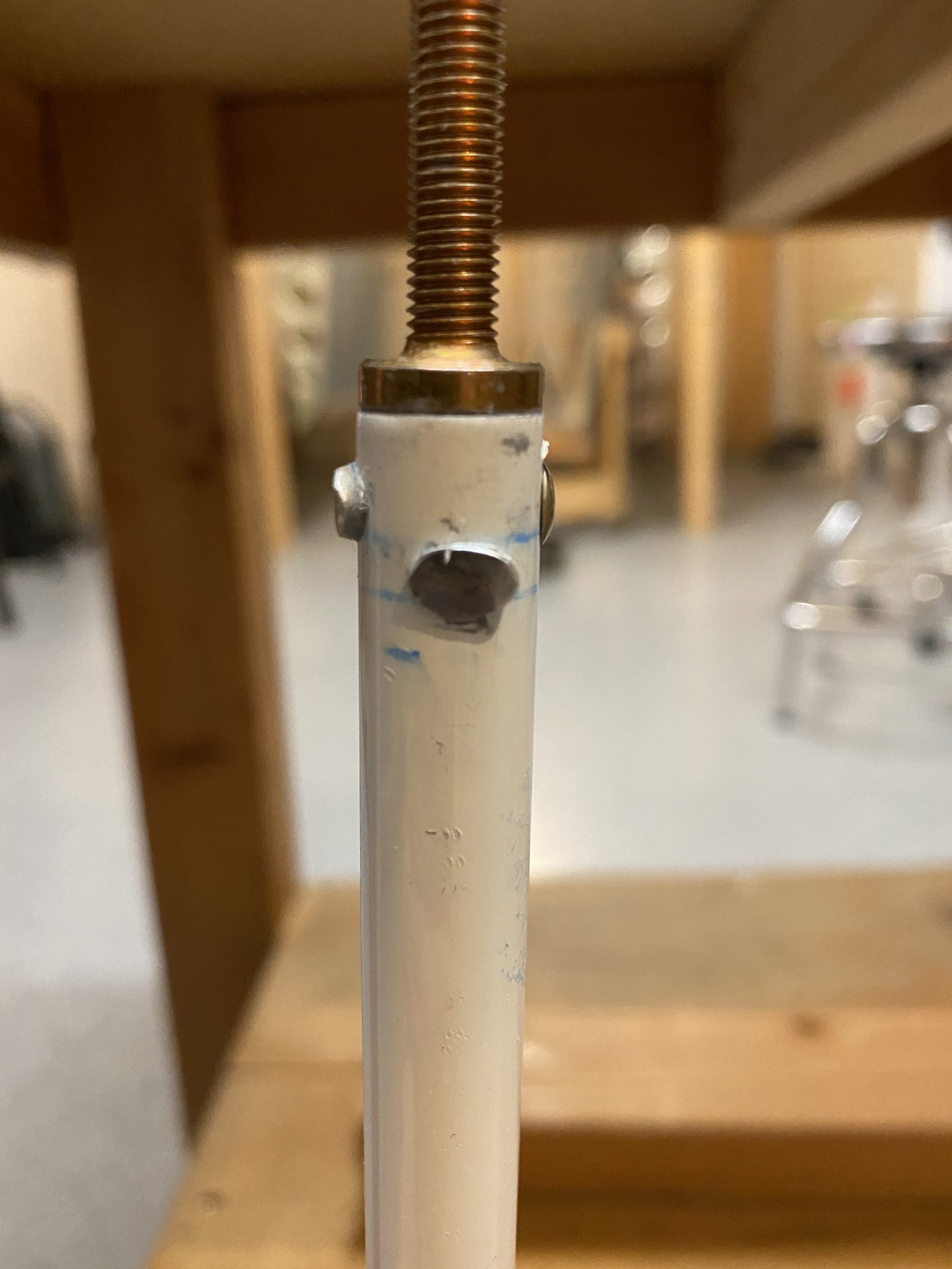
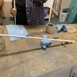
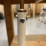
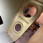
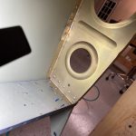
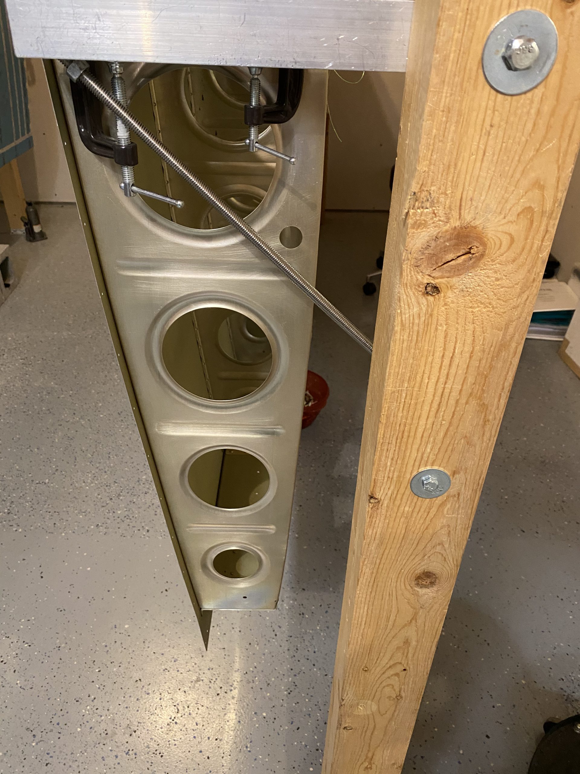
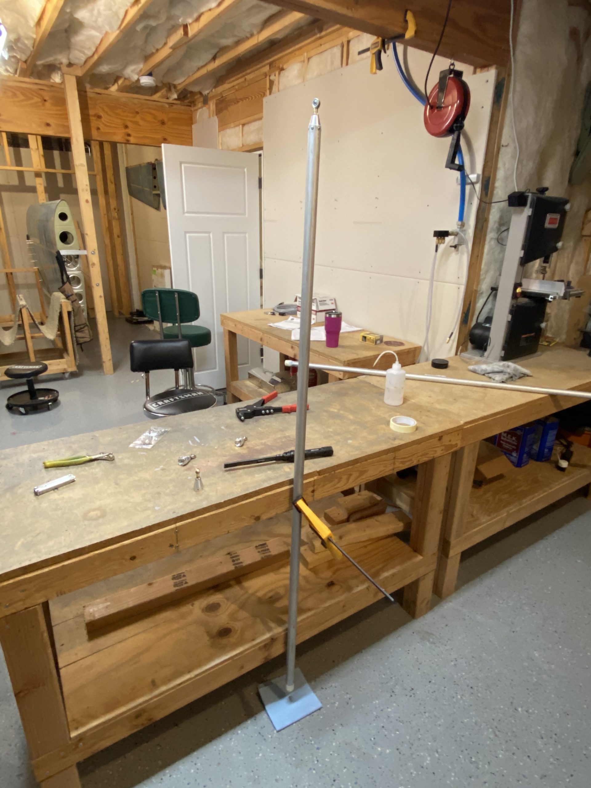
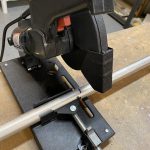
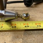
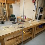
I decided to do something a little different.  I drilled a #12 hole in my workbench, big enough for an AN3 bolt to go in, and stuck a long AN3 bolt through one of the cleooed rod ends to hold it firm in my bench.

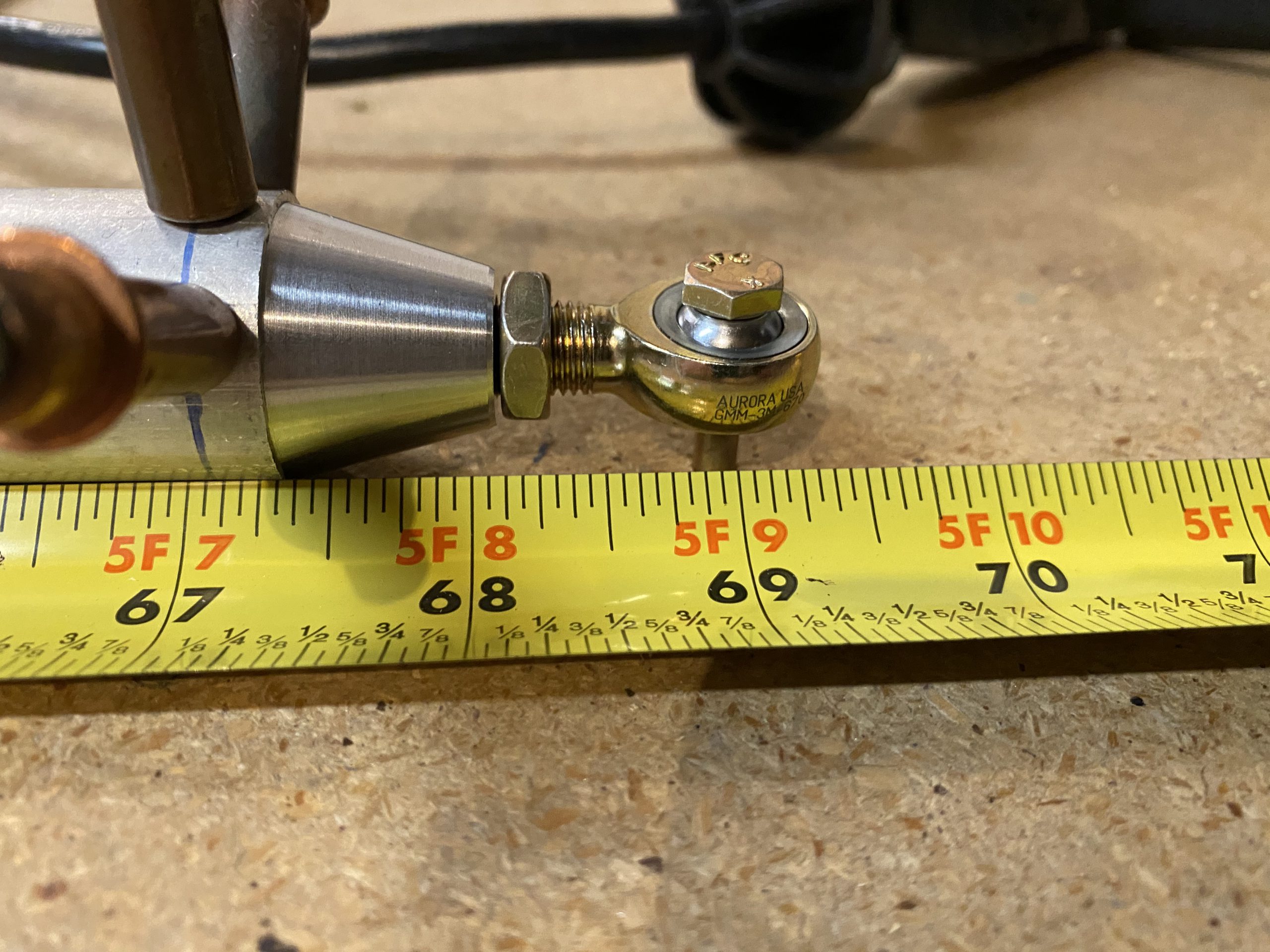
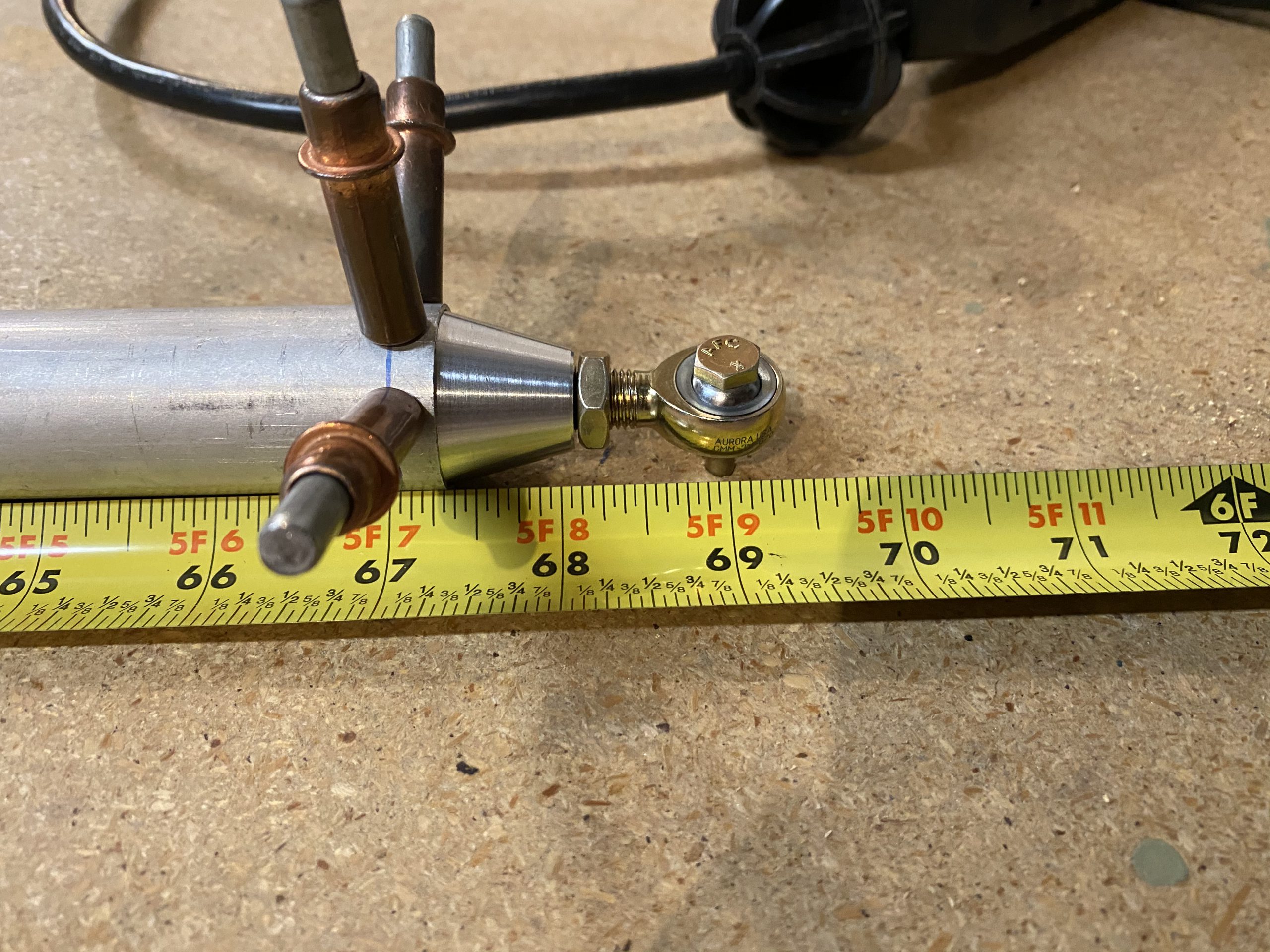
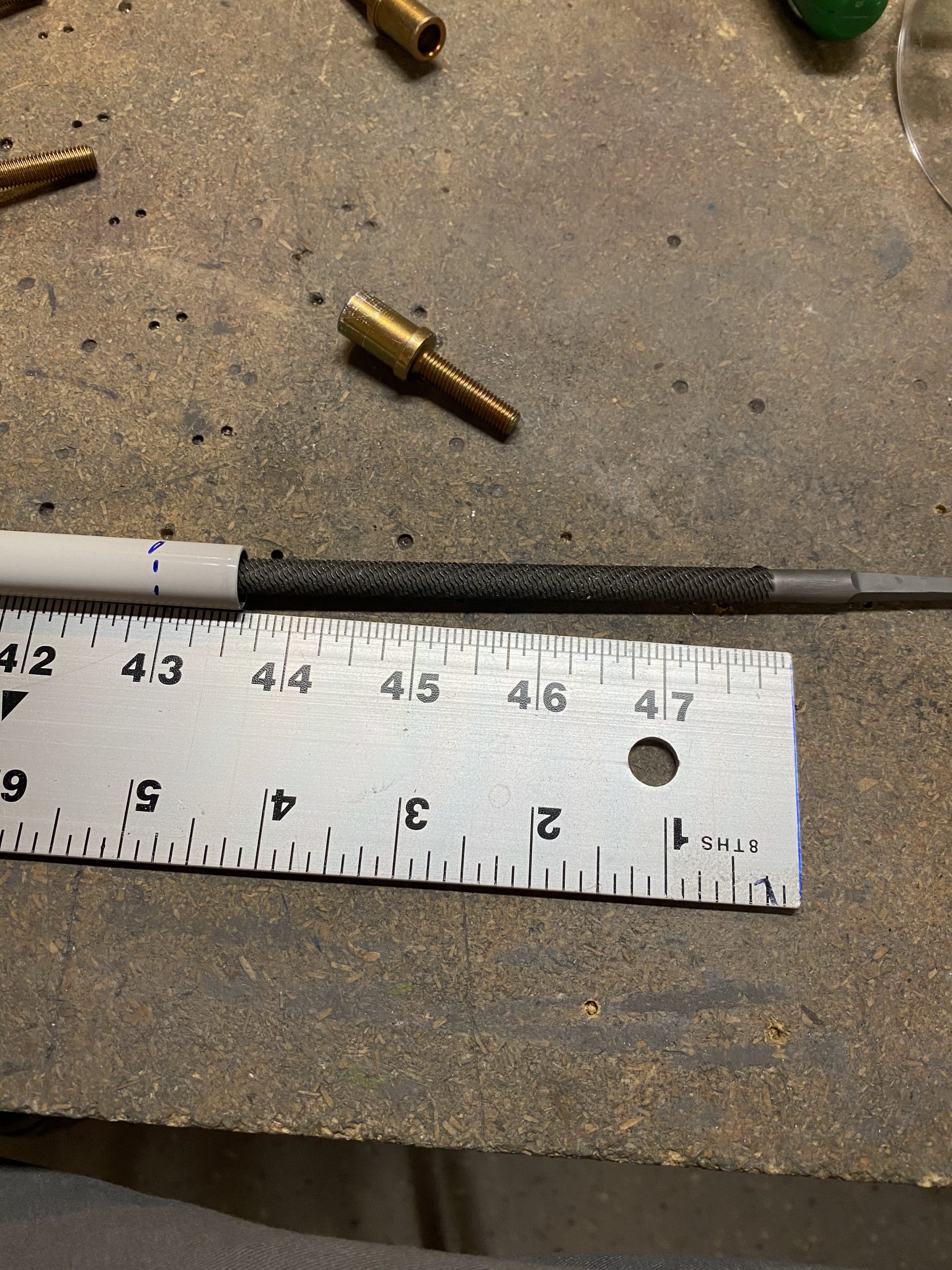
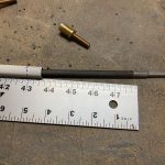
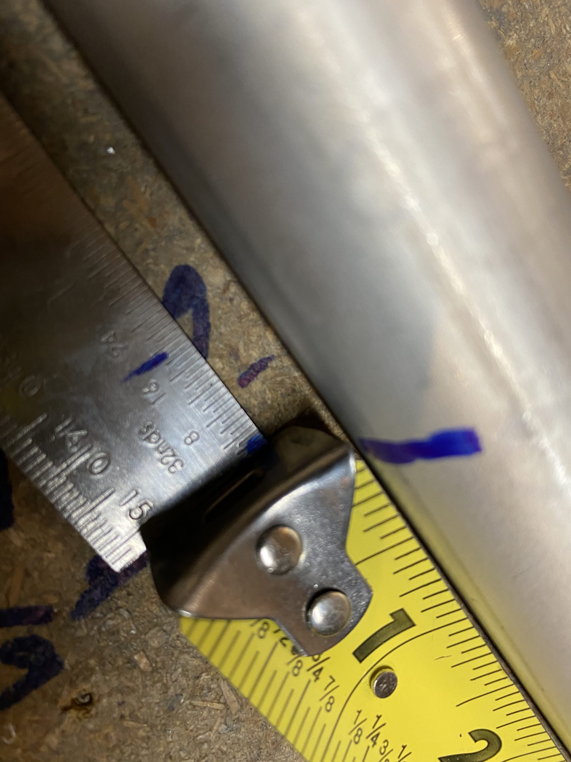
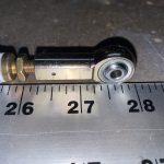
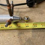
I had to get a little creating here.  The plans tells us we need a full 69 9/32″ length from the middle of the rod ends on each end of the tube.  I still need to trim my tube to fit this, so I measured out 69″ as my tape measure doesn’t go to 32nds.  Then I measured out from the end of the tape to meet that 9/32 with a machinist rule, and drilled another #12 hole.  I’ll use this hole to insert the other rod end in, to decide how long to cut my tubes to get to this end measurement.

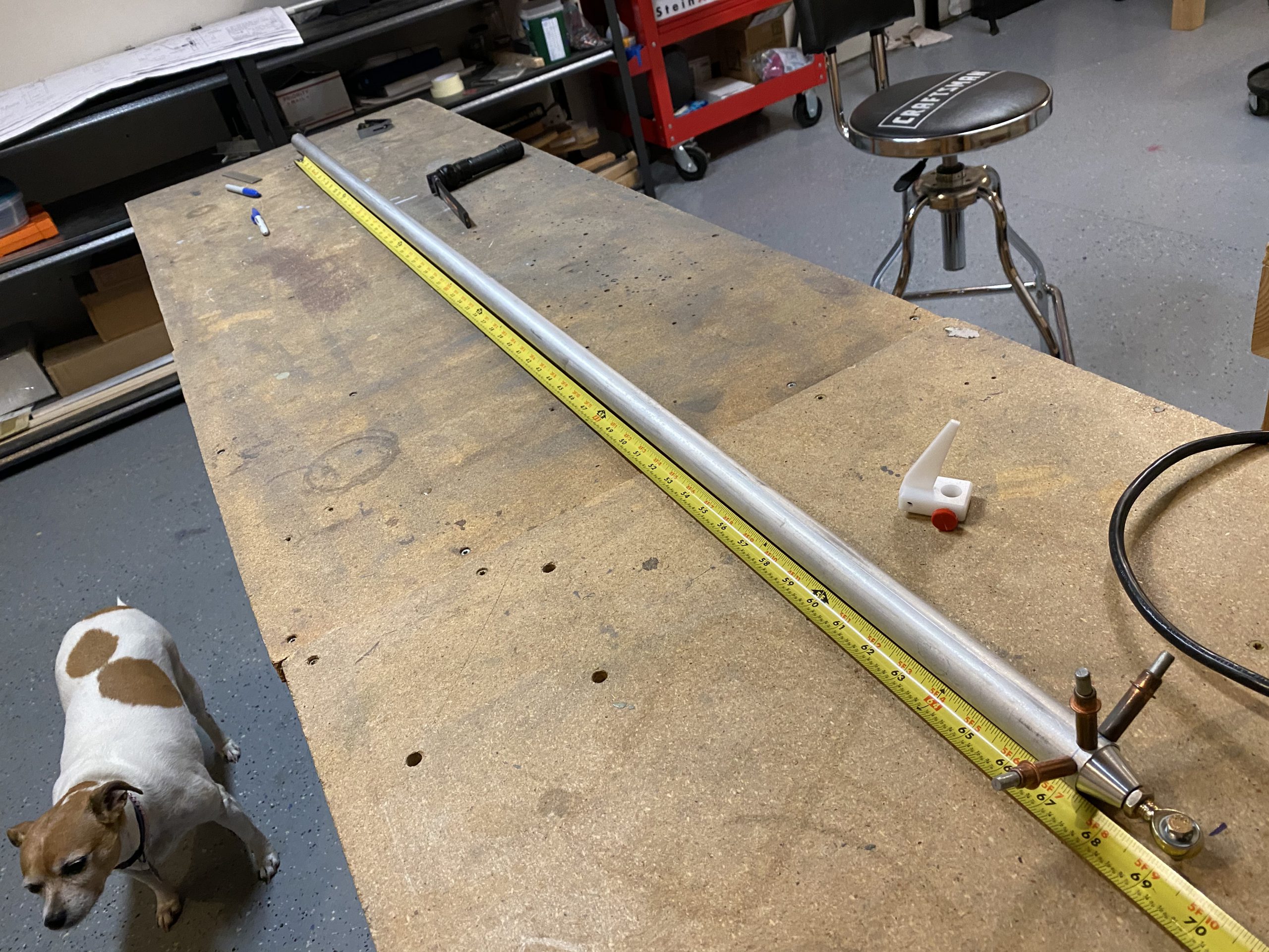
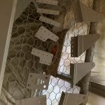
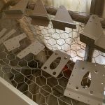
Now that I have a firm 69 9/32″ bolt holes, I can figure out where to cut the long end of my tube to get this exact measurement.  It turns out my tubes needed to be right at 66″ length.  This gave me about 1/16″ of extra overlap on the rod end, but certainly not enough to hurt anything.  Once I had both tubes cut to 66″ I marked, jigged and drilled these freshly cut ends for the rivet holes on the VA-111 just like in the steps above.  Then I deburred the edges and deburred the holes on each of the rod ends on each tube to get it ready for priming.

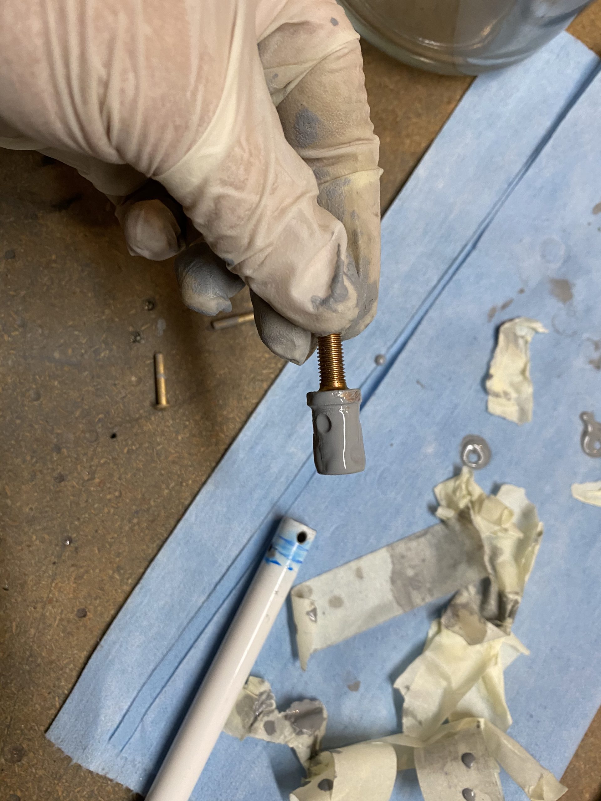
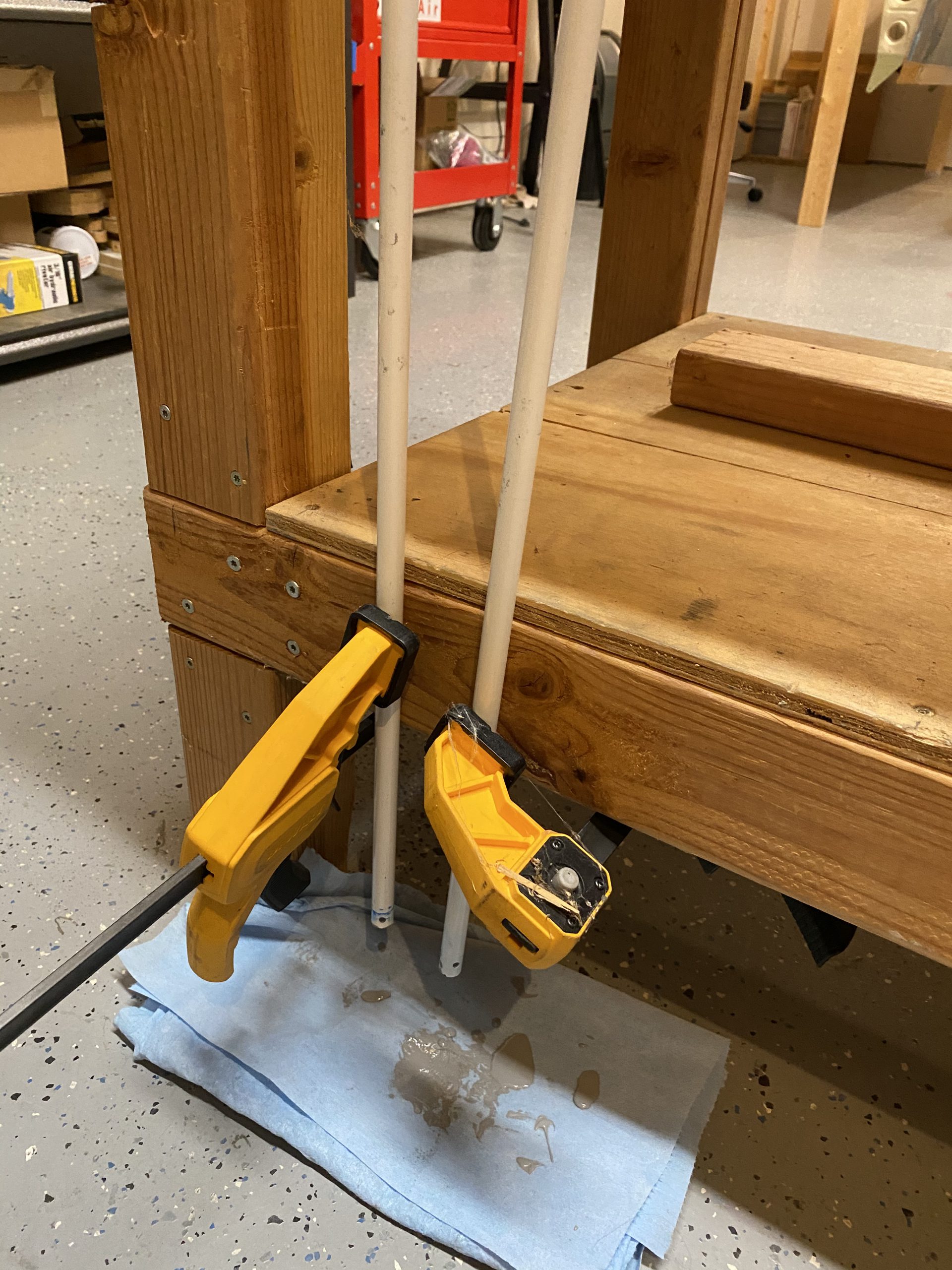
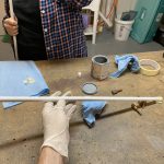
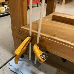
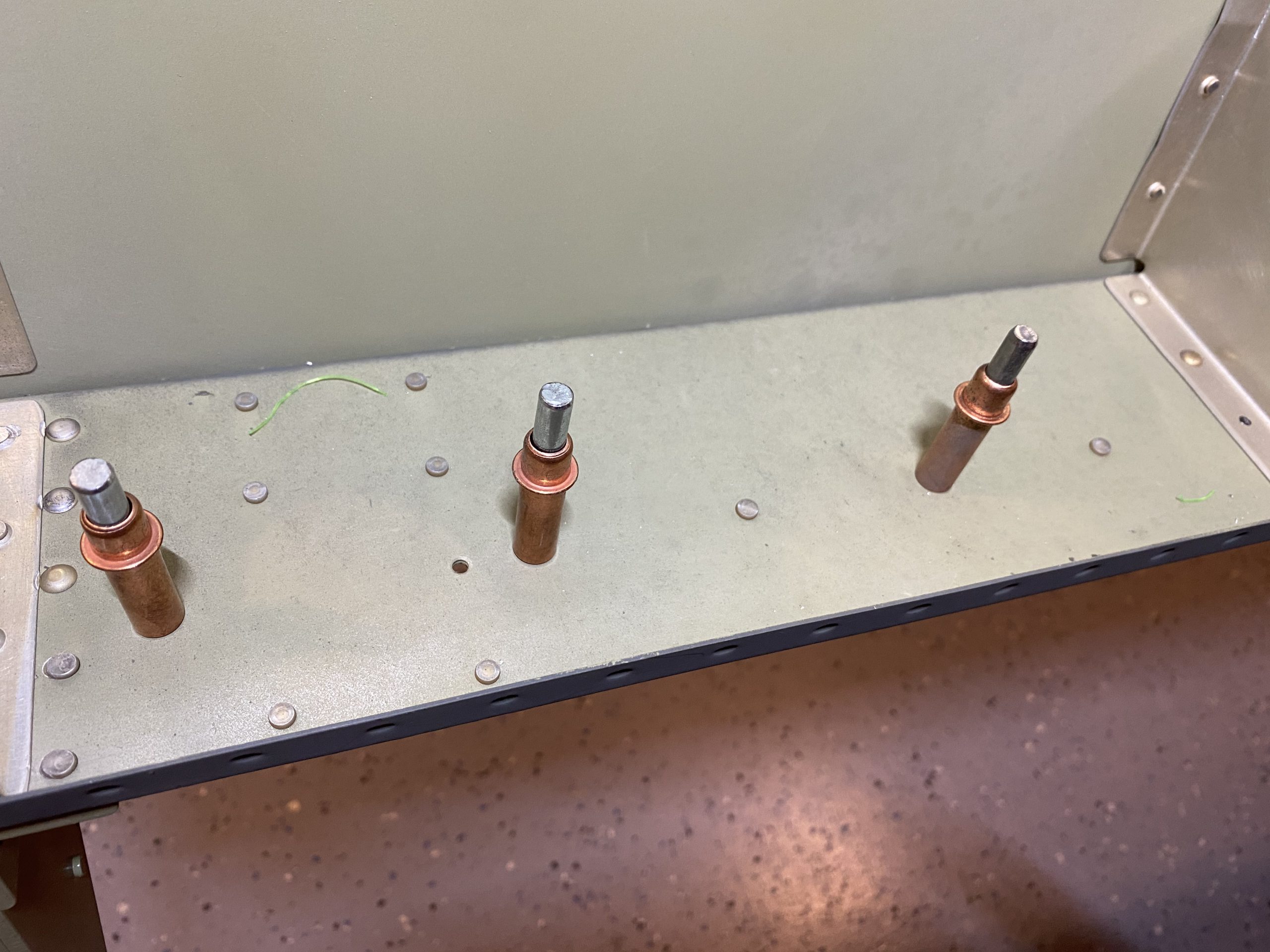
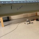
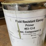
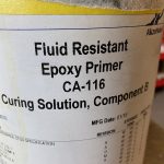
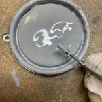
We only had enough primer to slosh around in one of the pushrod tubes.  We cleaned the tube with acetone, taped up one end and filled it full of the oil based primer and sloshed it around a good bit to get the inside of the tube fully covered.  Then, I grabbed one of the VA-111 threaded rod ends, and slathered on some primer and slide it into the tube.  I then grabbed the MSP-42 blind rivets, dipped the end in primer and set all 6 in only one end of the tube.

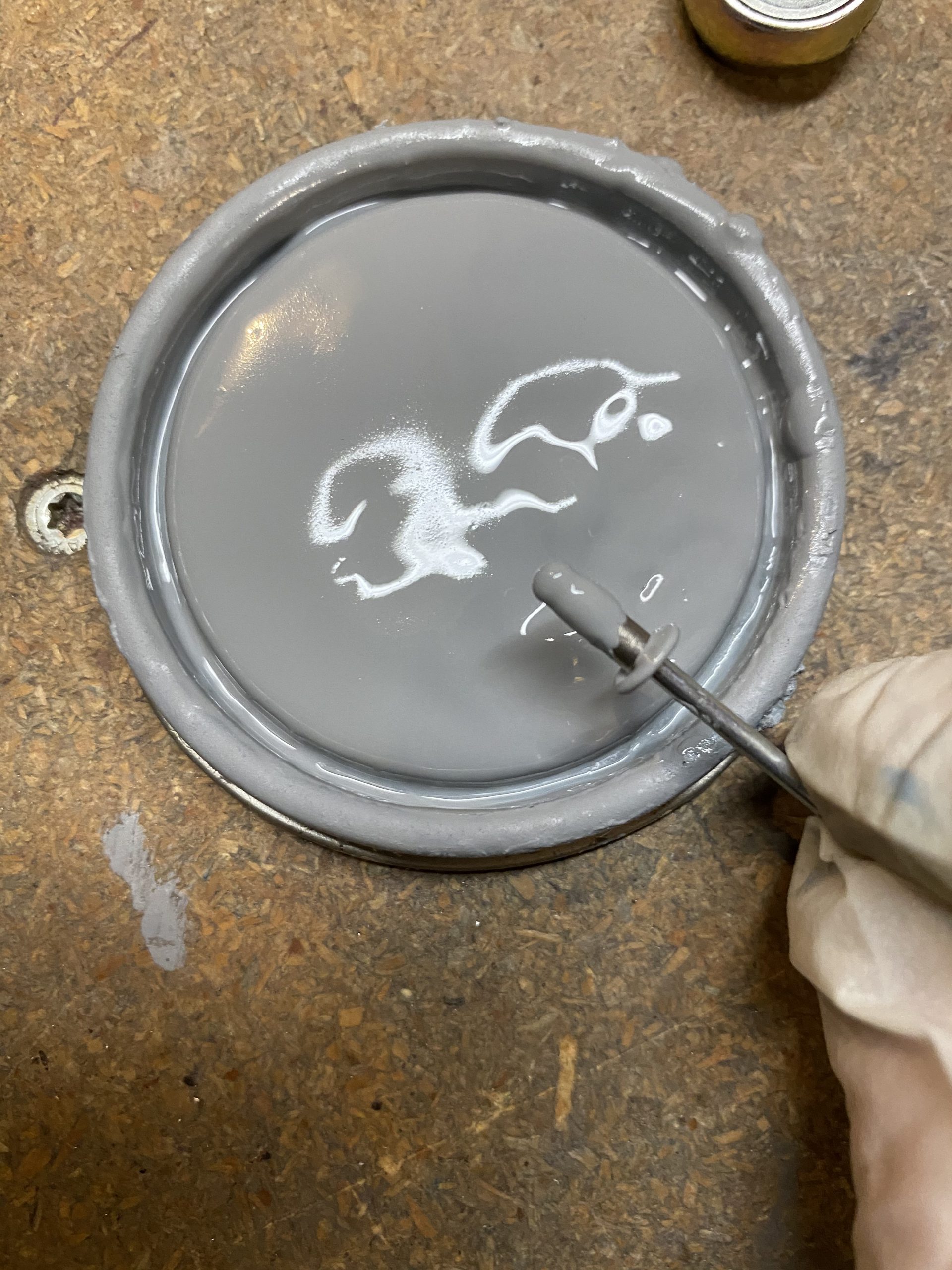
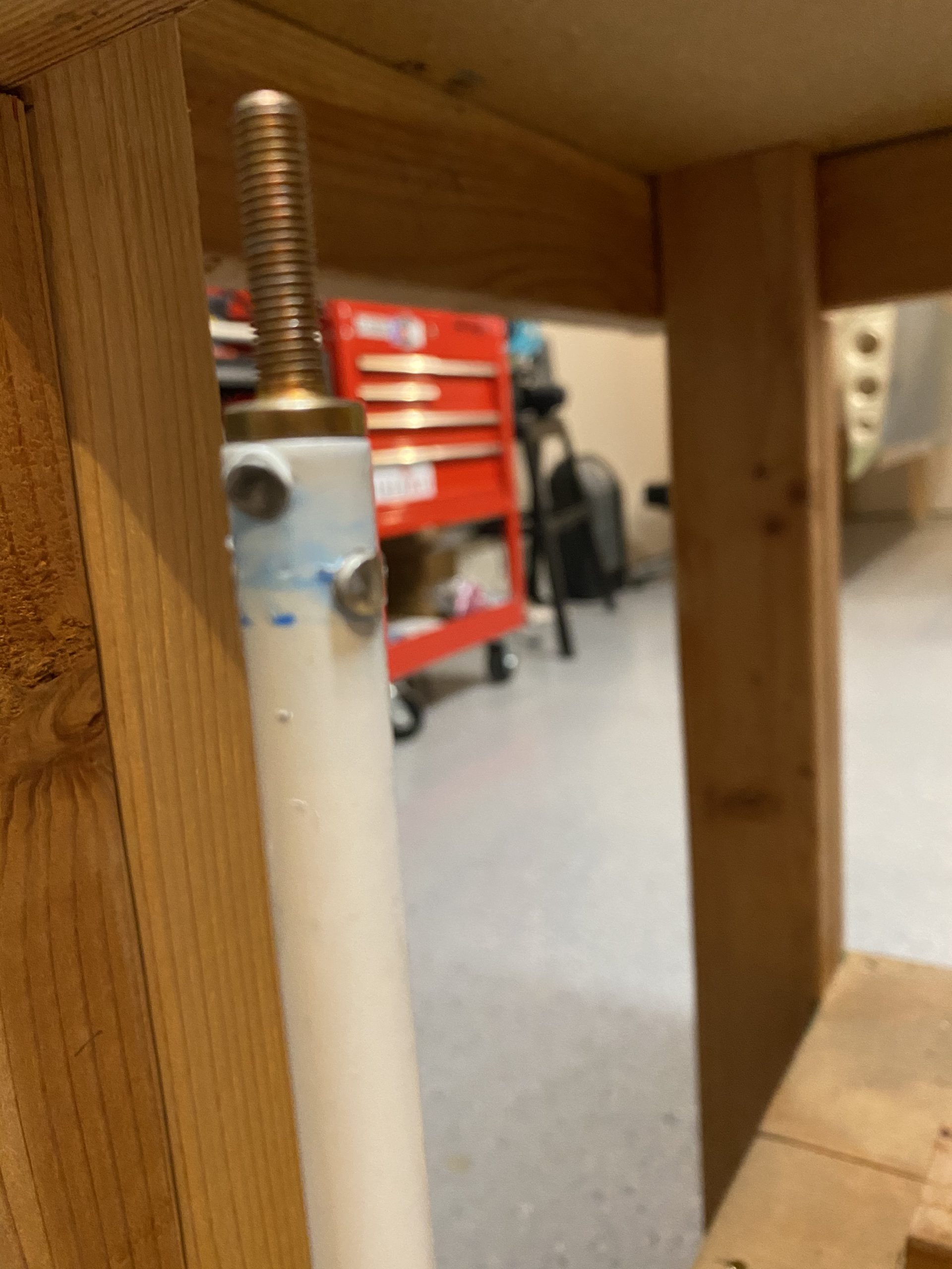
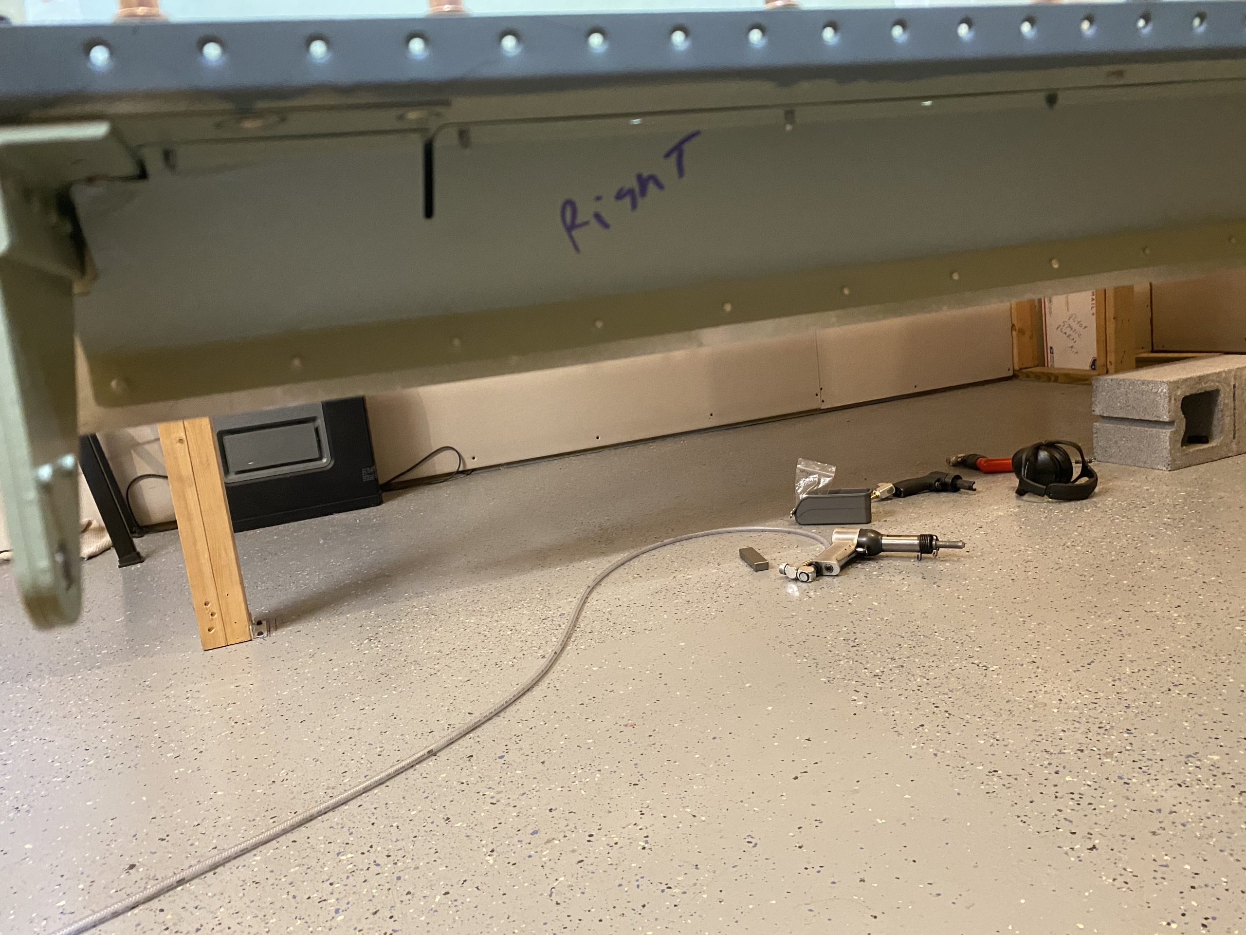
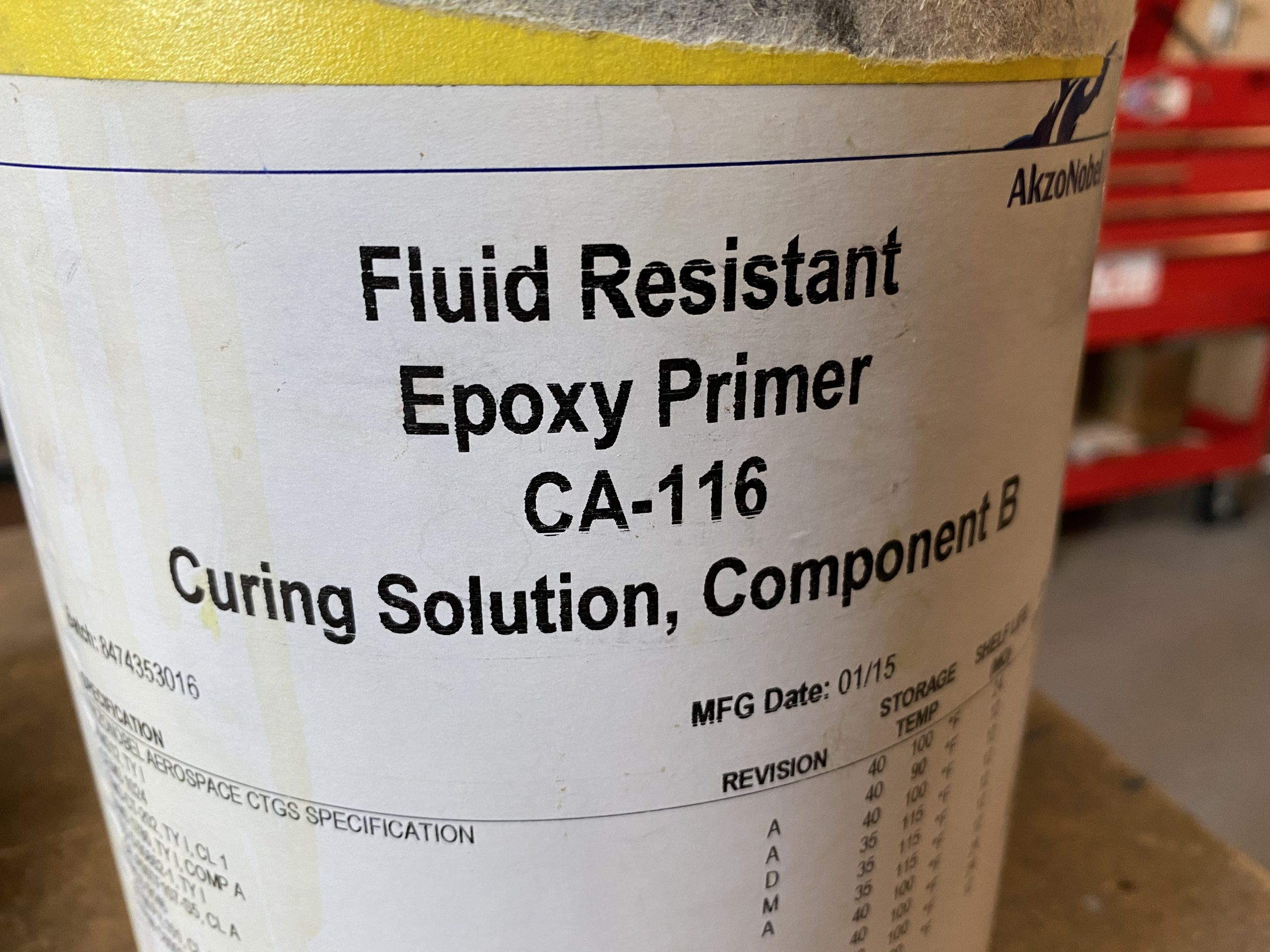
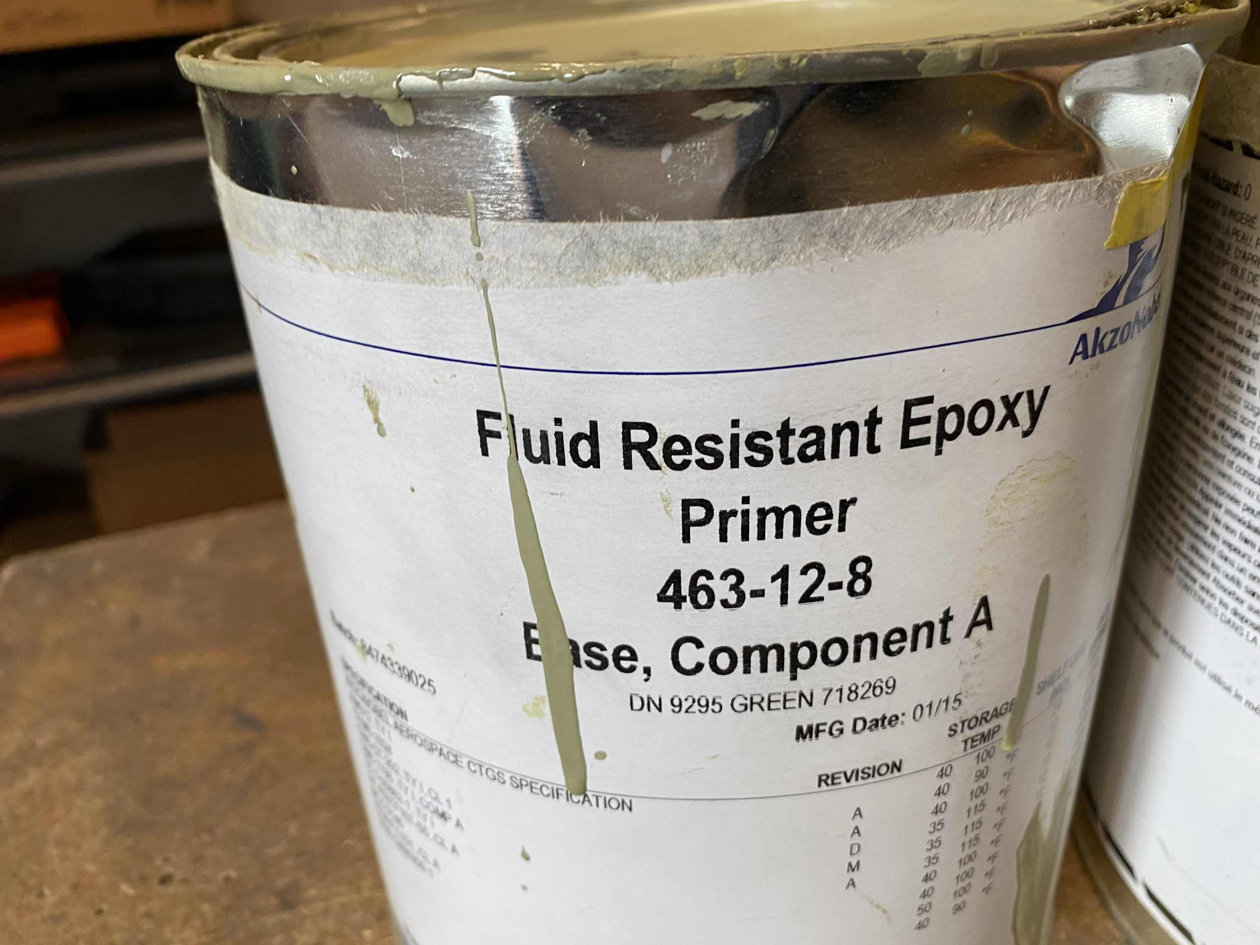
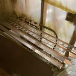
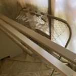
Lastly, I clamped the tube gently to my work bench with the open end facing down, so that the excess primer could drip out overnight, and also give plenty of air to help it dry and cure.  We ran out of primer, so we didn’t get to do the other push rod,  I’ll pick some more up tomorrow, and finish the other one off later.  For now, this one will drip dry for tonight.  I’ll need to order some AKZO to spray these tubes on the outside, as they are naked aluminum.  The oil based primer is perfectly fine for the interior, I want AKZO on the outside because its durable and tough as nails.


Google Photos Link:  https://photos.app.goo.gl/cSXjEoG75TGCPugg8

  • IMG_2852
    IMG_2852
  • IMG_2853
    IMG_2853
  • IMG_2854
    IMG_2854
  • IMG_2855
    IMG_2855
  • IMG_2856
    IMG_2856
  • IMG_2857
    IMG_2857
  • IMG_2858
    IMG_2858
  • IMG_2859
    IMG_2859
  • IMG_2860
    IMG_2860
  • IMG_2861
    IMG_2861
  • IMG_2862
    IMG_2862
  • IMG_2863
    IMG_2863
  • IMG_2864
    IMG_2864
  • IMG_2865
    IMG_2865
  • IMG_2866
    IMG_2866
  • IMG_2867
    IMG_2867
  • IMG_2868
    IMG_2868
  • IMG_2869
    IMG_2869
  • IMG_2870
    IMG_2870
  • IMG_2871
    IMG_2871
  • IMG_2872
    IMG_2872
  • IMG_2873
    IMG_2873
  • IMG_2874
    IMG_2874
  • IMG_2875
    IMG_2875
  • IMG_2876
    IMG_2876
  • IMG_2877
    IMG_2877
  • IMG_2878
    IMG_2878
  • IMG_2879
    IMG_2879
  • IMG_2880
    IMG_2880
  • IMG_2881
    IMG_2881
  • IMG_2882
    IMG_2882
  • IMG_2883
    IMG_2883

Hours Worked: 4.25

Aileron Pushrod Tubes – Part 1

After a short break, I came back down to do a little more work.  I decided to go ahead and make the W-818 aileron bellcrank pushrod.  We managed to get the W-818 pushrods made, and even got the inside primed.  Here’s the time lapse:

It started out by grabbing the ST4130-035 x 1/2″ stock tubing and marking up the cuts.  I need to measure out 23 13/16″ for each of these pushrods, luckily my 4 foot rule has 1/16″ markings.  So, I laid out the stock tube and made two marks using the straight cut on each end of the tubing.

You can see the blue sharpie marks here, and there is VERY little excess of tubing left after these cuts! The space between the two marks are the excess, since I measured out from each end of the tube.

I picked up a little cheap 6″ chop saw from Harbor Freight for this small work.  I don’t really need or have space for the big 3.5 HP model, and would likely never use it enough to justify the cost.  However, this little 6″ is compact, and was around $35, which seems perfect for cutting the stuff I’ll be doing with the airplane.  So, I set it up, and made my first cut on my blue line.  It worked really well!  I cleaned up the cut end with a flat bastard file, and then used a round file to deburr the inside edges of the tube.

I also had pulled the threaded ends AN490-HT8P threaded rod end so that I could start deciding where to drill the rivet holes.  I made a little blue dashed line to show where the very end of the threaded rod end would be inside the tube, to help me gauge where I needed to put my rivets, which was not an easy decision oddly enough!

Tammy was down helping me, so we measured and measured and tried all sorts of thing before finally coming up with what seemed like it would work.

You can see in the photos above, we decided to go slightly outboard of our marked lines to have plenty of clearance.  Once we decided, I used a center punch to mark the hole and help center the drill bit.  I went over to my drill press and used my drill press vice to hold the tubing while I lined up the drill bit.  This was a little bit of a challenge as I noticed my drill bit wanted to walk a bit, even in the drill press.

Here’s a quick video of drilling one of the holes:

Eventually, I had all the holes drilled through the pushrod tube, into the threaded rod end.  I did have to remove the rod ends, and deburr all the holes, for the holes inside the tubes, I used my round file to get in there and break those burrs.  I also stuck the AN470AD4-12 rivets in the holes to make sure they had clearance and everything looked good.

Vans tells us to prime the tube inside and out, but my tubes came prepainted a nice white finish on the outside, so we just needed to prime the inside.  Tammy used some oil based primer that is a rust preventer for steel, and taped up one end of the rods (after cleaning with acetone of course).  Then we poured the primer in the tube and rolled it a around a bit:

After rolling the primer around in the tubes for a bit, we pulled the tape off, and drained the excess back into the can.  Then I swabbed a little bit of primer onto one of a threaded rod end for each pushrod tube, and riveted it on to one end of each.

Now, I am not exactly happy with the way these came out.  I couldn’t squeeze them, they were too long.  So I put my bucking bar on the bench, and then sort of backriveted them with the dome head set.  The rivets tended to squish out oblong so I am not sure they are safe.  I’m going to ask the forums and send an email over to Vans to get some clarification if I need to try and drill these out and redo them.  If the rivets are a no-go, I may just take it to a machine shop and have them weld the ends on, as thats also another method Vans says can be used to secure them.  I’m no good at welding, but I know people who are 🙂

For now, I left one end off of each pushrod tube, and clamped them onto my bench with the open end down, so the primer could drip onto a paper towel.  This will also let air in to dry the primer on the inside of the tube.  I’ll let them sit like this for a day or two to dry.

Thats it for tonight.  I’ll come back to these in a few days, and in the meantime, I’ll work on the longer W-716 control pushrod tubes.  I am also thinking about adding some shelves to my wing cradle.  I am also going to need to get a small amount of AKZO or other primer for the longer pushrod tubes.

Google Photos Link: https://photos.app.goo.gl/aZbyH3ouysWQGTbt6

  • IMG_2829
    IMG_2829
  • IMG_2830
    IMG_2830
  • IMG_2831
    IMG_2831
  • IMG_2832
    IMG_2832
  • IMG_2833
    IMG_2833
  • IMG_2834
    IMG_2834
  • IMG_2835
    IMG_2835
  • IMG_2836
    IMG_2836
  • IMG_2838
    IMG_2838
  • IMG_2839
    IMG_2839
  • IMG_2840
    IMG_2840
  • IMG_2841
    IMG_2841
  • IMG_2842
    IMG_2842
  • IMG_2843
    IMG_2843
  • IMG_2844
    IMG_2844
  • IMG_2845
    IMG_2845
  • IMG_2846
    IMG_2846
  • IMG_2847
    IMG_2847
  • IMG_2848
    IMG_2848
  • IMG_2849
    IMG_2849
  • IMG_2850
    IMG_2850

Hours Worked: 2.75

Wing Cradle Caster Upgrade

I started tonights work with a little upgrade for the wing cradle.  I picked up some new casters at Harbor Freight, to make moving the wing cradle a little easier,  These have a 200lb each weight rating, and have brakes on each wheel, which will make it easy to lock the cradle in place so I can work on the wings.  I removed the old plastic casters, and then bolted the new ones on with 1/4″ lag screws.

The old casters have the stem that goes into the wood, which was a little wobbly, and would routinely fall out when I was moving the cradle.  These new casters have a plate that I can bolt on to the cradle.

It rolls SOOOO much smoother now.  A cheap upgrade for about $25 in casters.  They’re ball bearing as well, so they swivel very easily.  Next up I decided to drill out the 3 rivets on the skins that Tammy and I messed up when we riveted the skins on.  Out of all those rivets, 3 were bad, which is a decent ratio I think :-). They drilled out very easily, and I’ll leave them open until Tammy can help me rivet some OOPS rivets in there.  Maybe tomorrow.

Thats it for this quick session.  I went upstairs for a quick break, and then I’ll come back and do some more work.

Google Photos Link: https://photos.app.goo.gl/uNMk3tdWqh5uWTvNA

Hours Worked: 0.75

Assembling the Wing Cradle

Tonight was a pretty special night in the build.  I pulled from storage a wing cradle that was given to me by a fellow builder a few years back.  Marvin McGraw was putting the finishing touches on his beautiful RV-14 when I reached out to him to purchase his remaining AKZO primer….the same primer I just finished using a few days ago!  I bought what he had left over, and while I was up there picking the primer up, he offered to give me his old wing cradle, since he didn’t need it anymore.  Under one condition:  That when I get done with my using it to store my wings, that I pass it along to another builder and sign my tail number to it.  Sort of a hand-me-down wing cradle.

This means that my wings are very close to being done, and I’ll be soon ordering the fuselage, and hopefully soon after that, be handing this wing cradle on to the next builder.  I pulled it from storage, where I had it broken down to save space. It’s quite large when assembled, because it holds the wings!  Marvin did an excellent job building this thing, its super sturdy and even has casters on it!

The photo above and the photo below is where I am attaching those long beams back into the carpeted section that holds the leading edge. I had the two long beams that connect the two separate pieces stored in the corner of my shop, and the two end sections were stored in my garage, sort of packed and screwed together to make it more compact.

You can see here how the carpet forms a very nice and cushy, yet supportive place for the leading edges to lay in, with the leading edge facing down, towards the floor.

This is the other end, where the main spar beams will sit.  I am going to actually bolt the main spars to this section to prevent any mishaps from the spars slipping off this beam.  Highly unlikely, but worth the little time to do it.


And here is the entire wing cradle, fully assembled and ready for the wings! Marvin had installed some casters from an office chair on the 4 corners, but I think I will upgrade them to the same casters I am using on my DRDT-2 table.  Those things roll really nicely, and they lock with little brakes.  I am also thinking of adding some shelves between the two long beams, using the scrap wood from the wing crate.  This will let me put any of the wing parts on the shelf, and store them WITH the wings, out of the way.

I am still very grateful to him for giving me this awesome cradle.  This saved me a LOT of time building one myself, and I am looking forward to the day I get to pass it on to the next builder, with my tail number written on it.  And yes, its just barely wide enough to fit through the doors, to go into the garage.  You can see in the photo above, to the left.  That is the door from the shop into the hallway, and then across the short hallway there is the door to the 2 car garage.  Tammy and I confirmed, the cradle will indeed roll nicely through shop door, into the hallway, and straight across into the garage.  Thats one of the reasons I loved this house:  Easy access to transport the wings from the shop into the garage 🙂

I’ll post the upgrades that I do to the wing cradle, and try to get some more photos of it, before the wings go in.  Thats it for tonight! OH.. I did pull the tubing stock from the rafters in preperation for making the push rod tubes.

Google Photos Link: https://photos.app.goo.gl/ZBz4x66NyzZUbGfEA

Hours Worked: 0.75


Riveting on the Flap Braces

Another quick build session, but closing out some good work on the wings.  I was able to rivet both of the flap braces onto the wings.  Here are the timelapse videos:

And a closeup of the left wing:

Not much to report, I grabbed the flap braces and verified I had the right one for the correct wings, and then clecoed them in place, making sure I had clearance where the brace fits between the spar reinforcement bars.

In the photo below, you can see the wire from the resistive fuel sender dangling down from the fuel tank.  Yes, I made sure it wasn’t getting caught in the flap brace :-). I clecoed every other hole, and then inserted rivets.  I had to use a 1/8″ drill bit to clear out some of the excess primer, it tended to build up in some of the rivet holes enough to block the rivet.

I am NOT dimpling these just yet.  I am going to leave them undimpled (where it joins the skins) for now, as well as leaving the skin undimpled in this section.  I need to figure out how the flap hinge goes on, and if I need to countersink and/or dimple.  Its not going to be an issue, as I can dimple them later on, very easily with my squeezer even if they are attached on the wings.  Better safe than sorry.

Next up, pretty simple:  Check the rivet callouts, grab those rivets and then buck them in place.  I wasn’t able to get to them with the squeezer, so they all had to be bucked.  But, they were very easy to get to, and they came out looking really nice.

After I had the left wing flap brace riveted on, I moved on and did the exact same process on the right wing.  After about an hour, both were done, and there aren’t any more parts left on my shelf to attach to the skeleton! Its all control surface parts now, which is pretty exciting.  These wings are very very close to being done!

Google Photos Link: https://photos.app.goo.gl/ntmZxS6Cm6jdH8sb8

Hours Worked: 1.25

Riveting the Aileron Gap Fairing

I was able to get both the left and right wing aileron gap fairings riveted on the wings.  I captured the process in timelapse, heres those videos:

And a better close-up view:

I started out by dimpling the W-724 aileron gap fairings to accept the AN426AD3-3 rivets for the skin by using my DRDT-2 dimpler.  It didn’t take long at all to get both fairings dimpled.

Then I needed to also dimple the top wing skins, where these fairings attach.  I used my squeezer to dimple the skins.  There aren’t many holes here.  Once I had everything dimpled, i clecoed both fairings in place and grabbed the correct rivets.  I was able to use my squeezer to set most of the AN470AD4-4 rivets that attach the fairing to the rear spar, except for a few places I needed to buck them:  The rib holes, and the hole right next to the doublers for the aileron brackets.  Its to tight to get my squeezer in there, but the rivet gun fit nicely.

I did take note that we needed slightly longer rivets where the outboard rear spar doubler is, as well as where the rib holes are, but everything lined up with the plans.  You do get a bit better at identifying which rivet you’re gonna need for each hole.  I used my squeezer with the flat sets to squeeze the AN426AD3-3 rivets that attach the aileron gap fairing to the top wing skins.  I clecoed every other hole, and then squeezed the rivets, the same way I did with the AN470’s holding the fairing to the rear spar.

Once I had the left wing complete, I moved over and did the exact same procedure for the right wing. I am very happy with the way these came out, and how well the fairing reinforces the top wing skin.  It makes a very nice junction. Heres a few more shots of the completed parts:

Google Photos Link:  https://photos.app.goo.gl/qTqSewGPgprWvKto9

  • IMG_2779
    IMG_2779
  • IMG_2780
    IMG_2780
  • IMG_2781
    IMG_2781
  • IMG_2782
    IMG_2782
  • IMG_2783
    IMG_2783
  • IMG_2784
    IMG_2784
  • IMG_2785
    IMG_2785
  • IMG_2786
    IMG_2786
  • IMG_2787
    IMG_2787
  • IMG_2788
    IMG_2788
  • IMG_2789
    IMG_2789

Hours Worked: 1.75

Riveting the Aileron Brackets onto the Wings

Starting to get the last remaining parts from my shelf, and onto the airplane!  After I let the parts I primered, cure, they are ready to go onto the wings. I needed to get the aileron brackets riveted on, and I figured it would be easier to do with the wings in the stands for now.  Here’s the time lapse videos for the work:

I started by clecoing the left wing outboard aileron bracket onto the rear spar, as I’d need to back drill the holes into the outboard rib.  I double checked that everything was lined up correctly, and that I had the correct parts on the correct wing, and then back drilled into the rib using the aileron bracket as my guide.

Then I removed the bracket and deburred these new holes.  I also coutnersunk the lower two rivets on the side facing the aileron to avoid clearance issues.  Van’s instructs us to only do the very lower most rivet with an AN426AD4-7 rivet, but I went ahead and did the next rivet as well to be safe.  You can see them here:

The rest of the rivets I use the standard AN470AD4 style, and made sure to put the manufactured head on the thinnest metal piece, the rear spar.  I was able to squeeze a few of these rivets, but I did have to buck the others.  No biggies, they were easy enough to buck.  Next I moved on the inboard aileron bracket, making sure to apply proper doublers and rivets as called out in SB 16-03-28 for cracking.

I the same thinking, I used AN426AD4-9 countersunk rivets for those bottom two rivets, to avoid clearance issues. Like I did on the outboard bracket, Vans calls for the lower most rivet to be flush, but I did the one right above it as well.  I was able to squeeze some of these, and bucked the rest. I’m happy enough with how they came out, I have one rivet I will probably drill out and re-do because It sort of folded over a little.  Should be easy to fix I think.   Next up was to repeat this process on the right wing, and it was exactly the same as the left wing, just mirrored 🙂

Thats it! Both wings have their aileron brackets installed.  I’m going to save drilling out that rivet, as I need to drill out 3 in the wing skins.  So I’l all of them at the same time.  This work went pretty quick, and I’m glad I primed these brackets as they look really nice, and should give a long service life.  I think I’ll get the aileron gap seals and flap braces installed in the next session.  I also need to start putting thought into the fuselage kit order soon :-). There’s more photos in the album below.

Google Photos Link: https://photos.app.goo.gl/2B1t79pMpFiK1WFp6

  • IMG_2759
    IMG_2759
  • IMG_2760
    IMG_2760
  • IMG_2761
    IMG_2761
  • IMG_2762
    IMG_2762
  • IMG_2763
    IMG_2763
  • IMG_2764
    IMG_2764
  • IMG_2765
    IMG_2765
  • IMG_2766
    IMG_2766
  • IMG_2767
    IMG_2767
  • IMG_2768
    IMG_2768
  • IMG_2769
    IMG_2769
  • IMG_2770
    IMG_2770
  • IMG_2771
    IMG_2771
  • IMG_2772
    IMG_2772
  • IMG_2773
    IMG_2773
  • IMG_2774
    IMG_2774
  • IMG_2775
    IMG_2775
  • Image 2020-09-27 at 10.57.22 PM
    Image 2020-09-27 at 10.57.22 PM

Hours Worked: 1.75


Priming Aileron Brackets and Seals, Flap Braces, and Bottom Skins

Another BIG work session done with the help of my wife Tammy!  We managed to get all the bottom skins, aileron brackets, pitot parts, flap braces, and aileron seals primed during this work session.  I thought I captured two time lapse videos, but I must have bumped the camera on one of them.  Here’s the overhead view:

We started the session by scuffing the parts with scotchbrite.  Tammy did the flap braces and aileron seals, while I focused on the bottom wing skins.  I used a orbital sander with a scotchbrite pad to make quick work of the skins, then did a little finishing work with a pad in my hand.  Tammy got her parts scuffed and she went back upstairs, as the MEK and Acetone I use to clean the parts makes her woozy.

Once we had all the parts scuffed, I moved them into the paint booth to help evacuate the fumes from MEK and Acetone outside using the ventilator fan.  I cleaned all the skins, flap braces, ailerons seals and brackets, and the few little pieces of the pitot mast with MEK first, following that up with Acetone until the paper towels came up clean.

About halfway in the cleaning process, I mixed up the last remaining bits of my AKZO.  I had enough to mix up a full 3m PPS cup (10 ounces?), and then about 4 ounces in a second cup.  I went ahead and mixed up every last drop I had, as these were the last parts I’ll be spraying with AKZO, and no sense in leaving a few ounces in the can for months.  I let it sit to kick for its 30 minute induction time, which worked out pretty nicely time wise.  While it was inducting, I laid out all my parts for spraying:

Here’s the empty cans of AKZO, for my future reference on what I need to re-order 🙂

After I got the flap braces, and aileron seals and brackets sprayed, I still had plenty of AKZO let in my gun, so I decided to go grab my pitot mast, and the aileron bracket doublers to get them sprayed too.  They were cleaned with acetone, and were already alodined, so they were ready for priming.  I laid them on the wire mesh and gave them a good coating of primer:

I even had enough left in my gun to spray a little more on each of the skins and other parts.  Sure, its adding a few ounces of weight, but these skins will be on the bottom, and could possibly collect water, so its worth spraying it, than tossing the extra primer in the trash.   I was pretty stoked to get all these parts primered, and having enough AKZO to get all these done.  Heres how the parts are looking:

After I got everything sprayed, I left the parts in the booth to off gas with the ventilator running, I cleaned up my spray gun with acetone, trashed all the used 3M cups, and then tidied up the workshop.  This will more than likely be the last priming job for a while.  I’ll need to prime my control tubes, but I need to decide if I am doing AKZO on those or JetFlex.  Thats a good ways away however.  I’ll let these parts cure overnight, and start putting them on the wings, except for the bottom skins of course 🙂

Google Photos link: https://photos.app.goo.gl/BaKivbz9uNgfuMFw6

  • IMG_2734
    IMG_2734
  • IMG_2735
    IMG_2735
  • IMG_2736
    IMG_2736
  • IMG_2737
    IMG_2737
  • IMG_2738
    IMG_2738
  • IMG_2739
    IMG_2739
  • IMG_2740
    IMG_2740
  • IMG_2741
    IMG_2741
  • IMG_2742
    IMG_2742
  • IMG_2743
    IMG_2743
  • IMG_2744
    IMG_2744
  • IMG_2745
    IMG_2745
  • IMG_2746
    IMG_2746
  • IMG_2747
    IMG_2747
  • IMG_2748
    IMG_2748
  • IMG_2749
    IMG_2749
  • IMG_2750
    IMG_2750
  • IMG_2751
    IMG_2751

Hours worked: 3.0

Riveting the Right Wing Top Skins

Tammy helped me rivet the right wing top skins tonight! We had a sitter at Nana’s house, so we went down and got the last portion of two-person riveting done tonight.  I captured the entire work session in timelapse, hers those videos:

Closer view of the riveting process:

We started out by getting setup with the tools, and picking the right rivets per the callouts.  We followed the plans. but riveting the inboard skin first, starting in the middle of the middle rib of the inboard skin and working our way forward, then aft, every other hole (the other holes clecoed), and then moved over to the next rib.  Once the inboard skin was riveted in every other hole in the ribs, we moved to the outboard skin and did the same process of starting in the middle and working out, forward and aft.

We left the leading edge portion of the skins until after the ribs were done, followed that up by riveting the lap joint to make sure the skin stayed nice and tight.  Finally, we finished it up by squeezing the rivets on the rear spar – to – skin, making sure to not miss the spots that had longer rivets due to the doublers.  It came out very nice!

Across both wings, we only have 3 rivets to drill out and reset, so thats REALLY GOOD!  We made sure to mark them with sharpie, and I’ll drill them out this weekend and have her help me rebuck them.

After that, I cleaned up the shop, and then removed the wing stand brackets on the rear spar as they aren’t needed anymore, and they need to come off so I can rivet the aileron brackets.  We have two partially skinned wings!

 Thats it for this session! I am planning on doing a large priming session this weekend for the bottom skins, flap braces, and aileron seals and brackets.   Really happy to have made this huge milestone on the wings! they are both officially ready to come out of the jigs and into the cradle.

Google Photos Link: https://photos.app.goo.gl/oSo7YswPDxnf3pqk9

Hours Worked: 3.0

Deburring the Bottom Wing Skins

A quick update on this one. I’ve decided to do one big priming session this weekend to be efficient. Planning on priming all the bottom wing skins, the aileron brackets, flap braces and aileron gap seals all in one go.  So, I needed to get the deburring work done on the bottom skins.  I grabbed the inboard and outboard skins for both wings from their storage area, and put them on the bench and went to work!  Here’s the time lapse that shows the work.  I took a short break for dinner in that video 😉

Pretty straight forward:  I rounded all the corners of the skins with my bastard file then used the file on all the edges to smooth out the shearing marks.  Then I used a scotchbrite pad to completely finish all the edges on the skin getting them nice and smooth.  After that, I used the edge breaking tool to put a small break on the edges where the skin laps, or lands on the spars so I’d get a very nice rivet line.  Finally, I removed the blue plastic from the interior side of the skins, as I’ll be scuffing them and priming them this weekend.  Thats it! I’ll probably get setup to prime tomorrow.

Hours Worked:  1.25