Fitting the Left Tank Fuel Sender

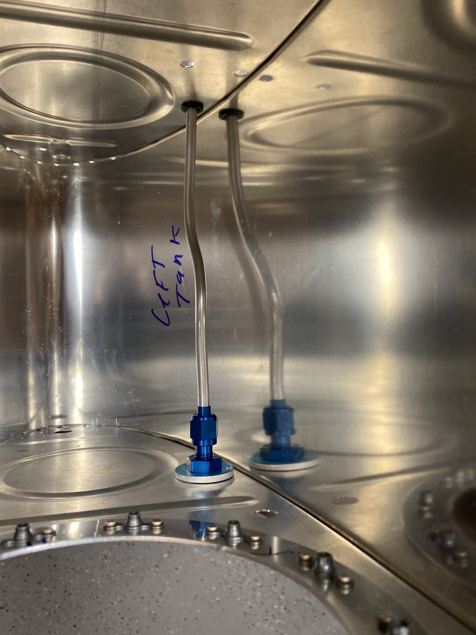
Tonight I was able to accomplish a part of the fuel tanks that I’ve been worried about.  The left tank fuel sender.  My left tank is my “acro” tank, and as such has a flop tube installed in the inner most bay, and that forces us to move the float style fuel sender into one of the inner bays.  That brings its own problem:  You can’t use the end rib access plate to install the sender, leaving you to custom cut and mount the fuel sender in the baffle itself!  I’ve read up on this for a bit, and put a bunch of thought into it, and I decided a way to tackle it.  At this point, I am also out of rubber gloves so I can’t do any more sealant work, and with COVID-19 going on rubber gloves are sort of hard to find!  So, I figured I would work on this as its coming up REAL quick and this would be a good time to go ahead and get this done.

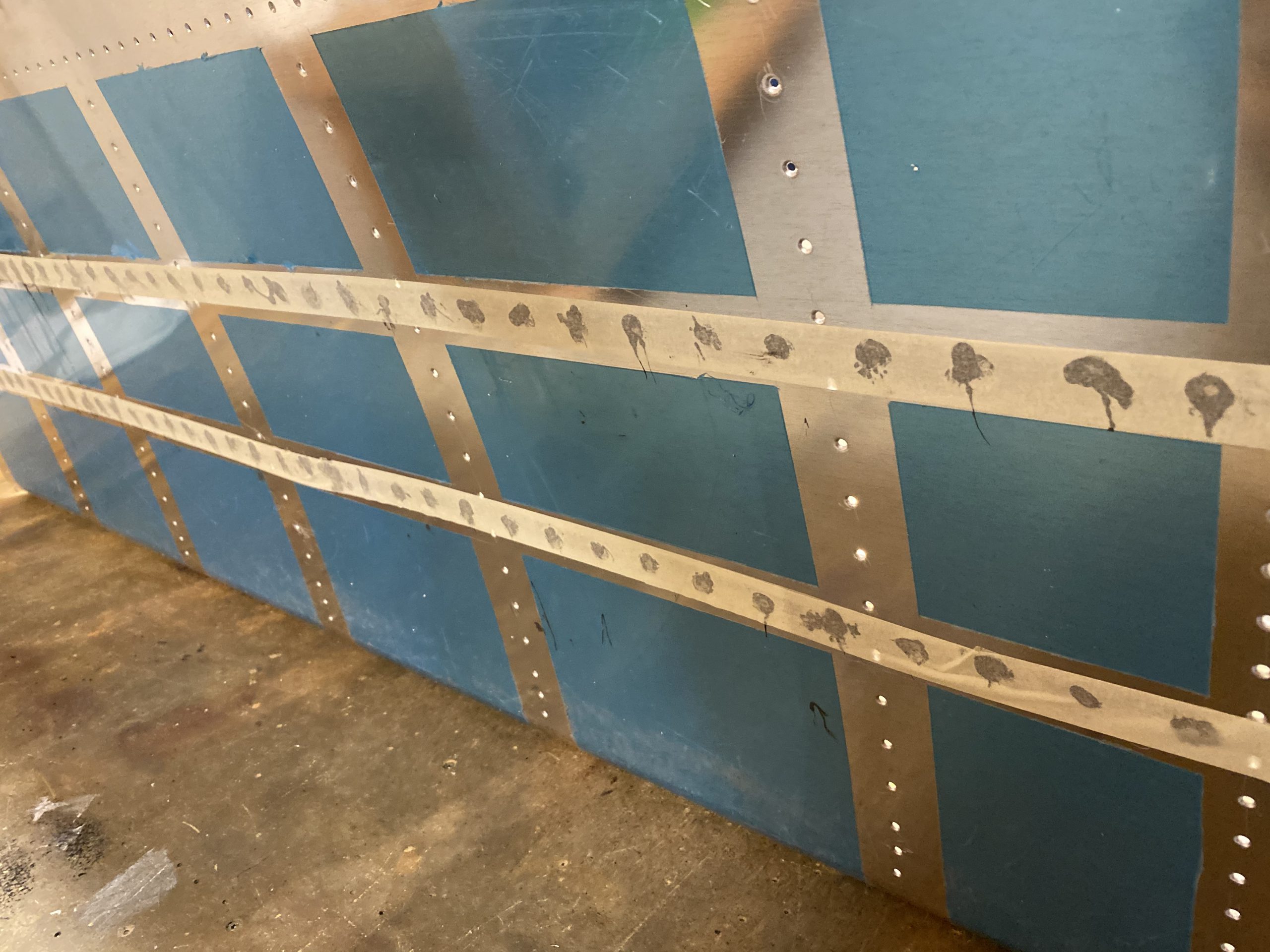
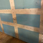
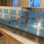
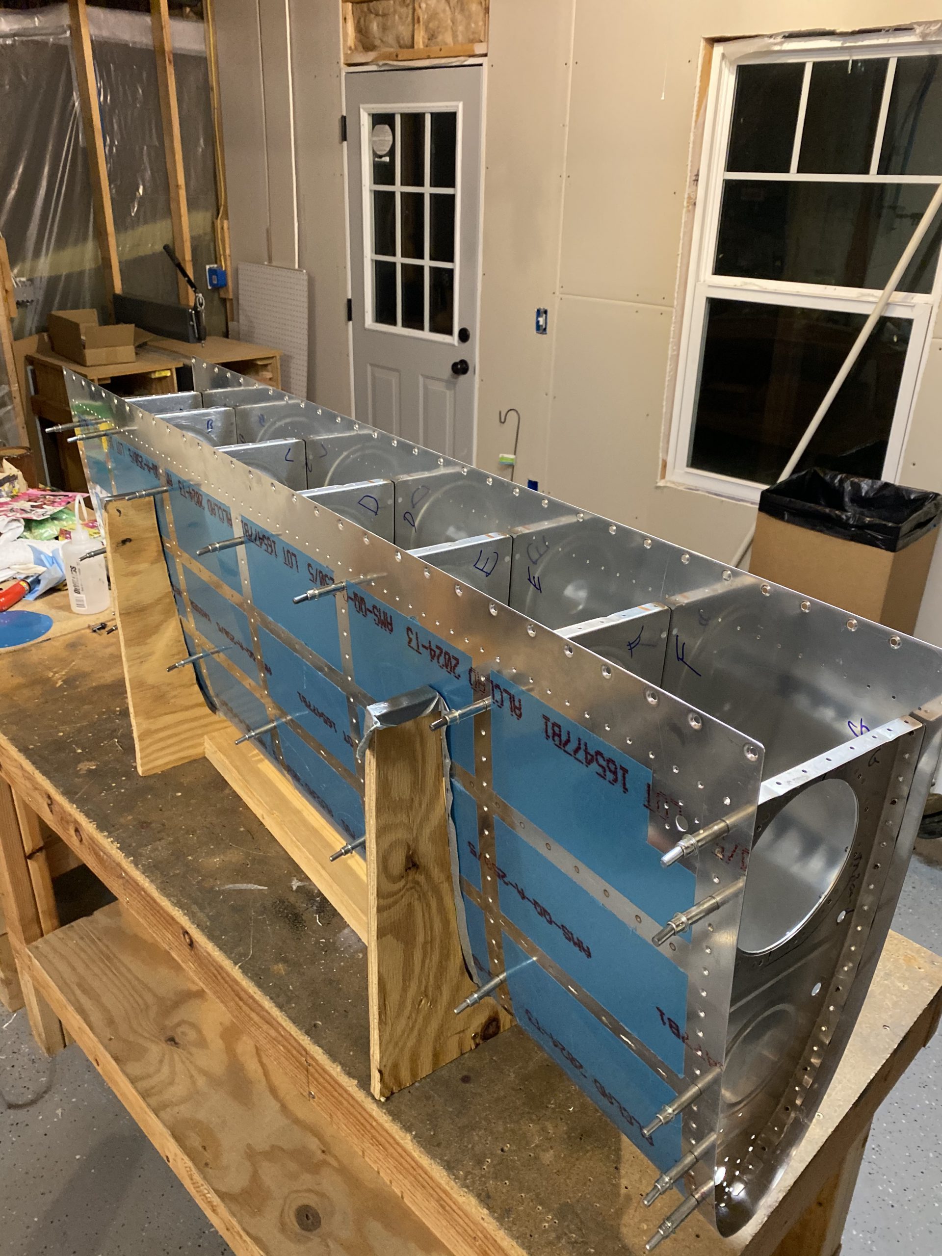
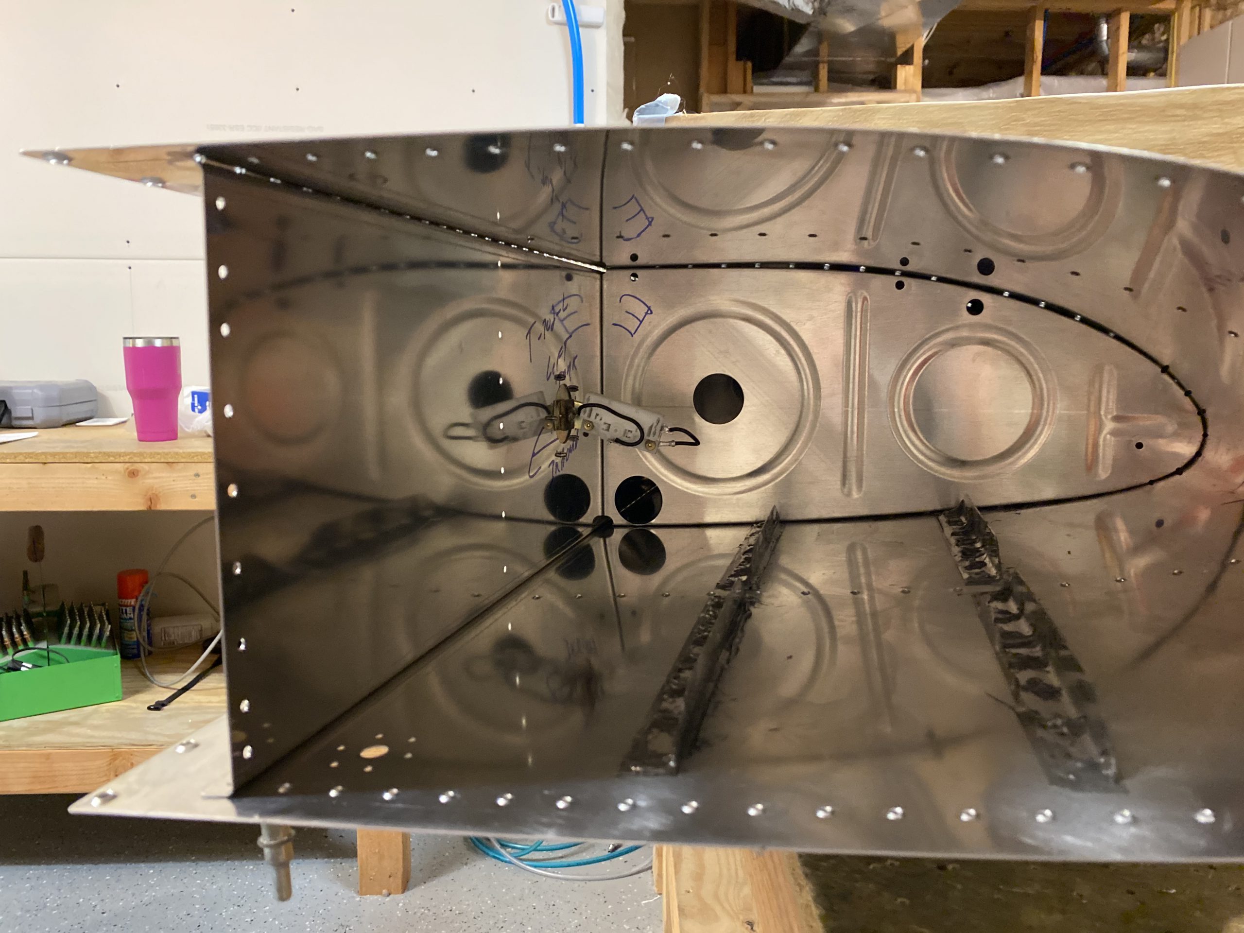
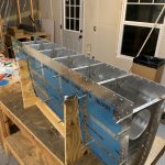
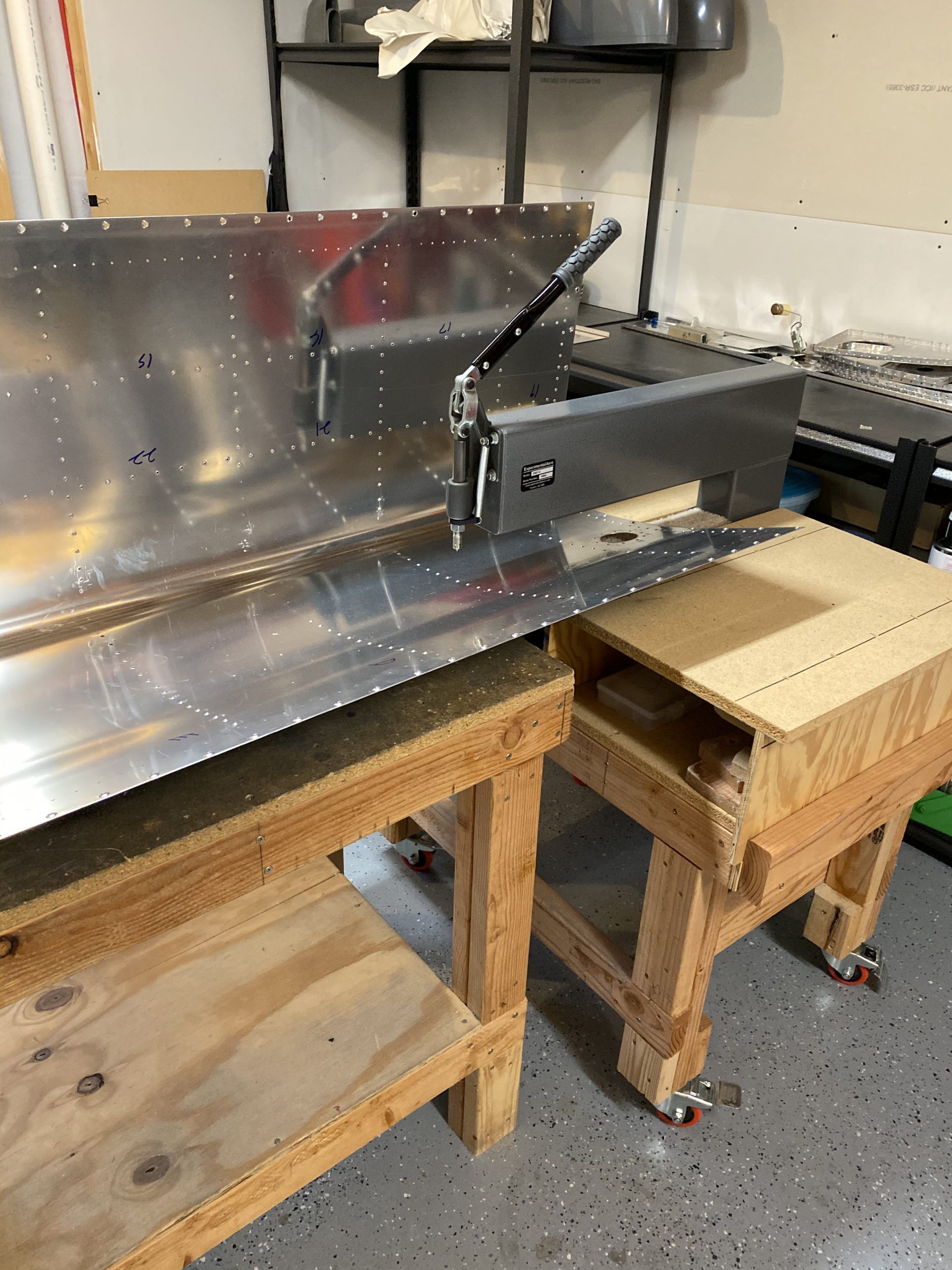
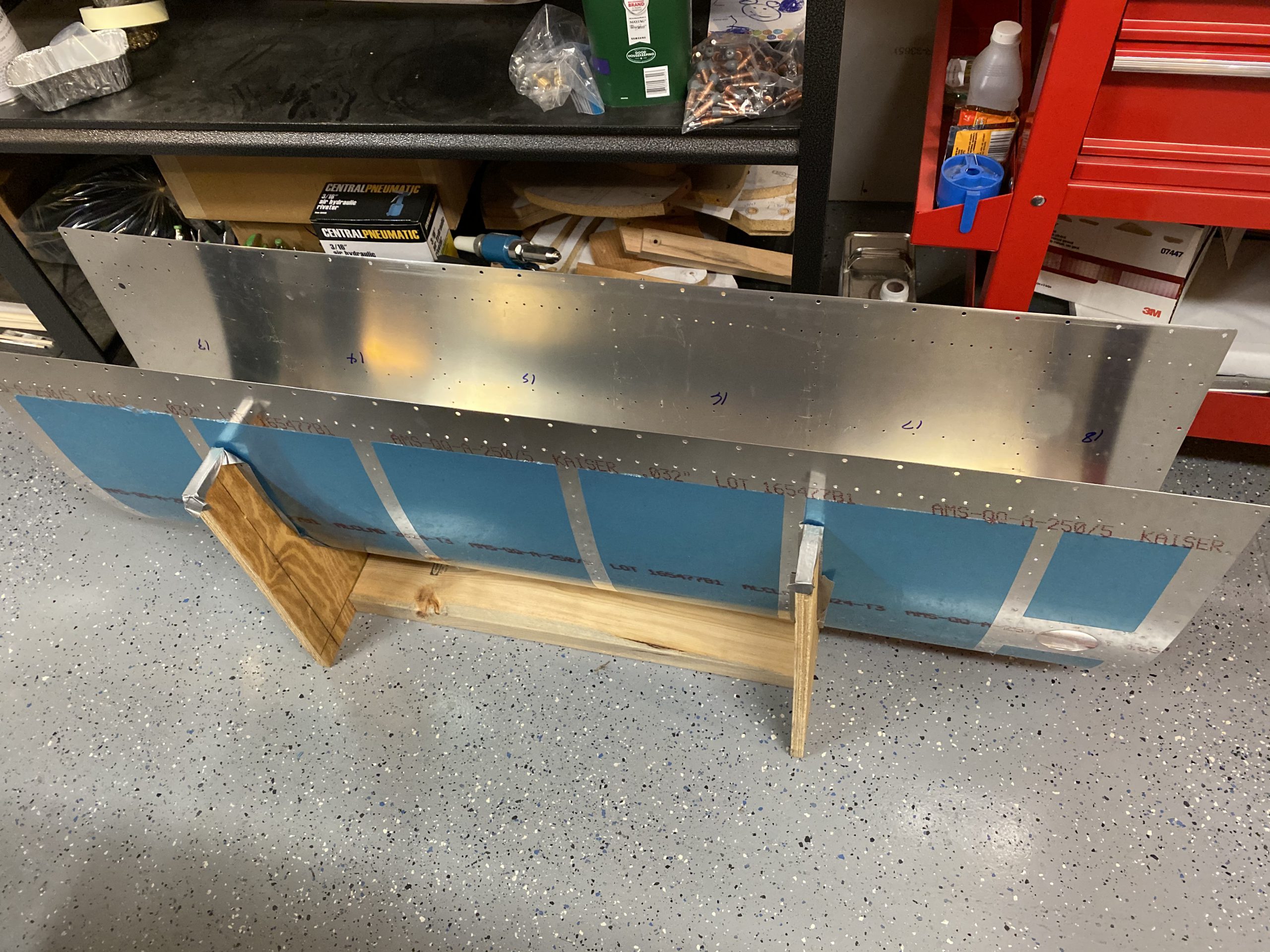
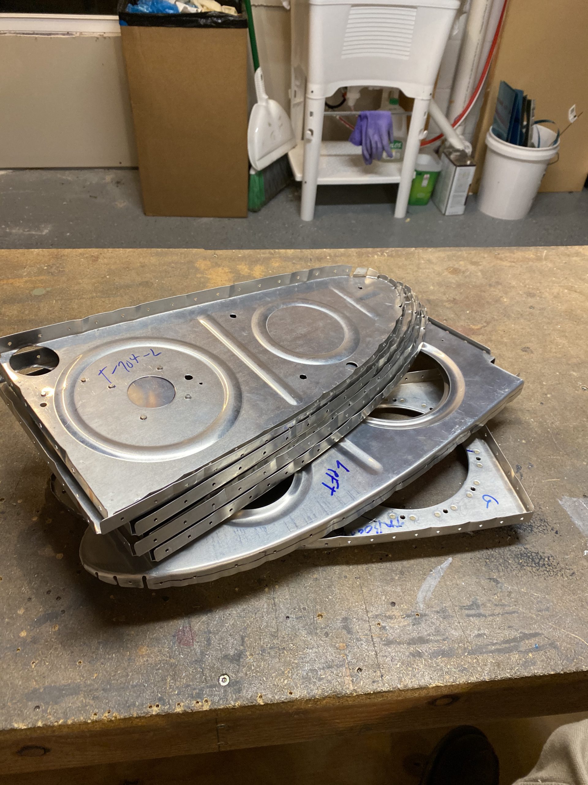
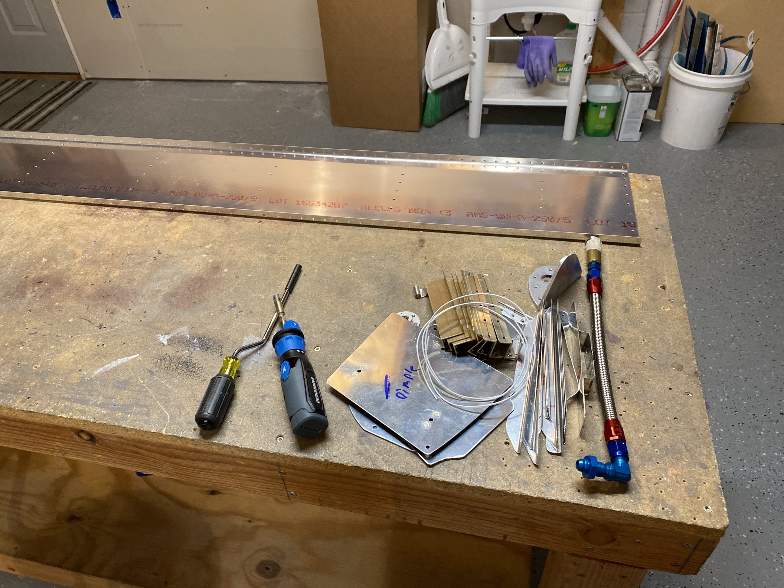
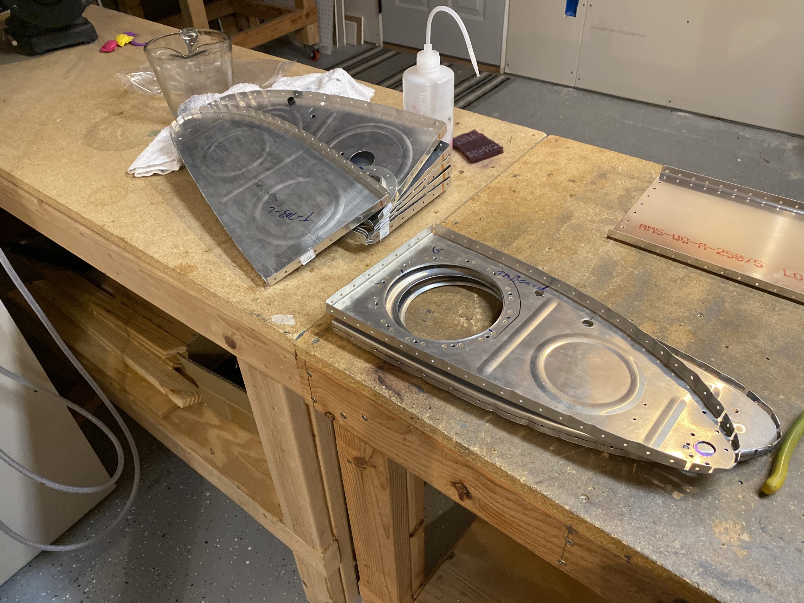
I started out by sticking the left tank into the leading edge jig, and fitting the ribs back in and clecoing them in place.  I left out the two inboard ribs, so that I could see the sender and be able to adjust the float wire accordingly.

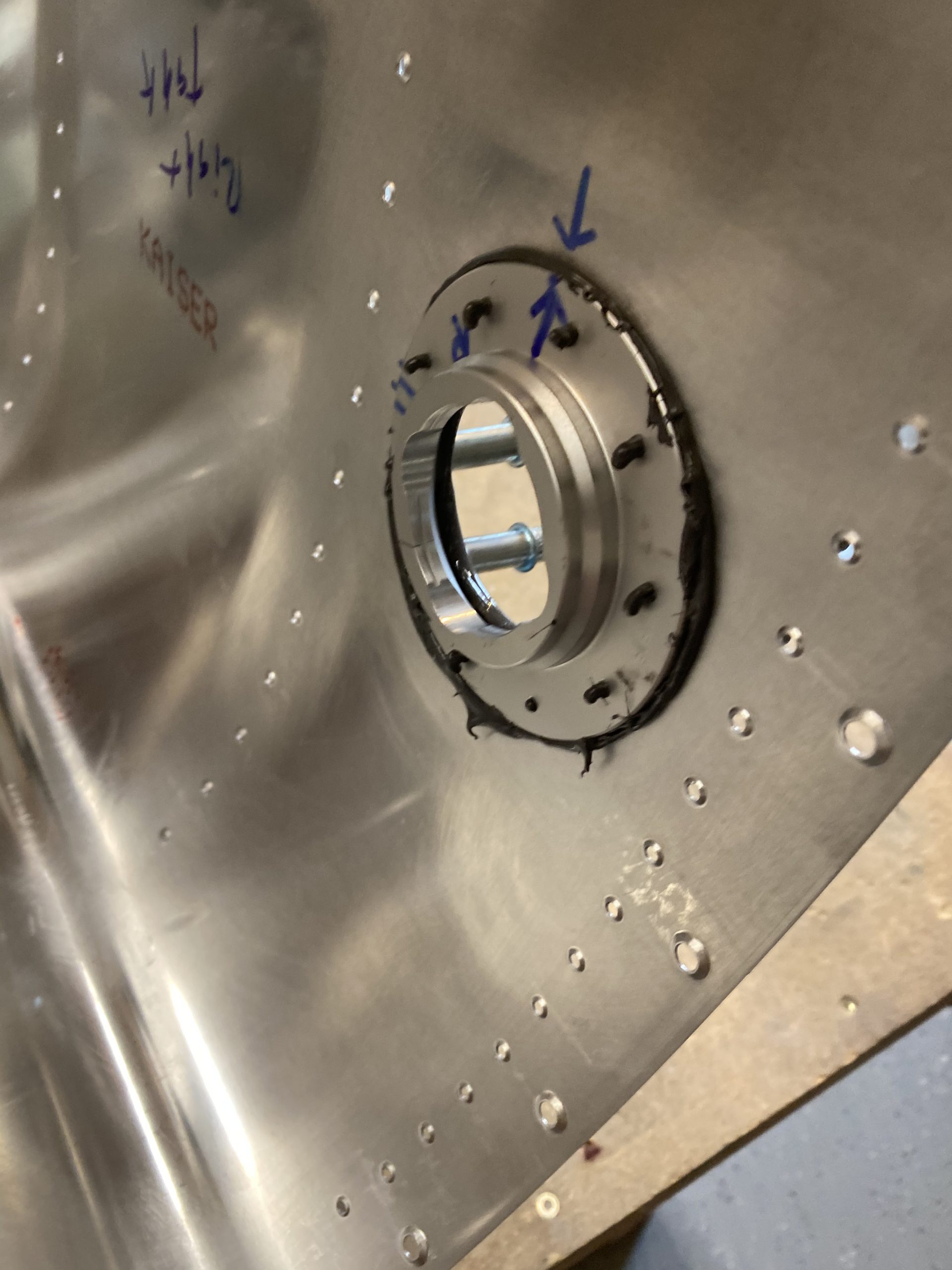
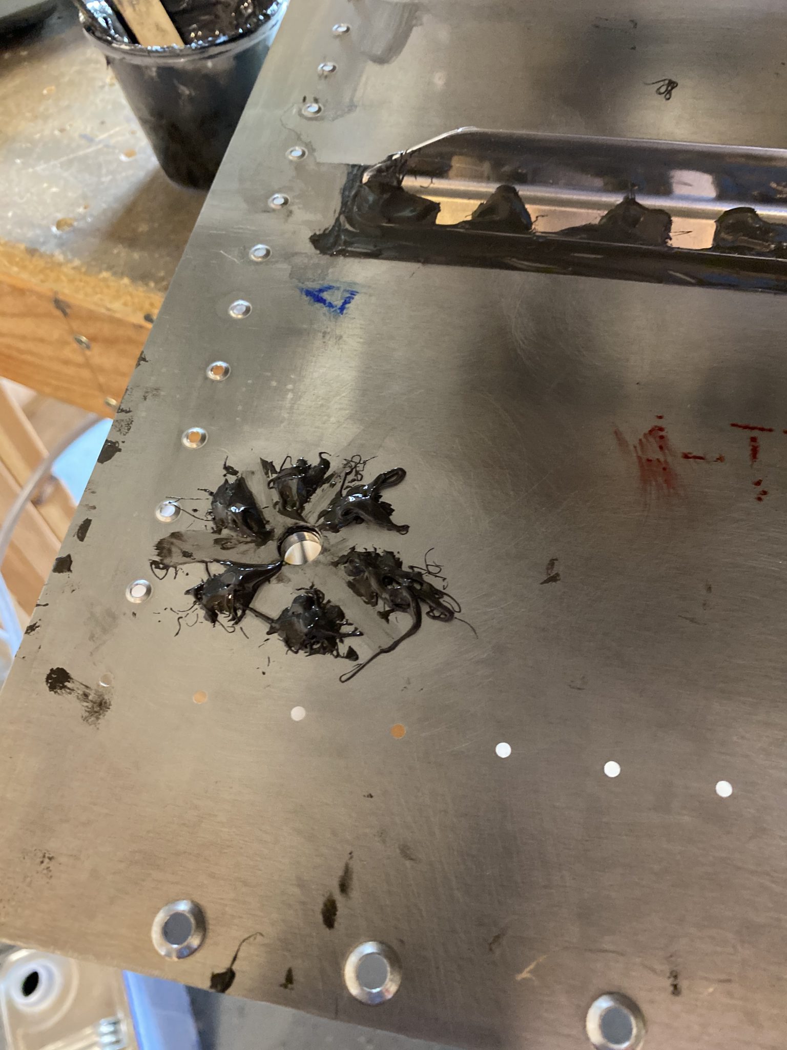
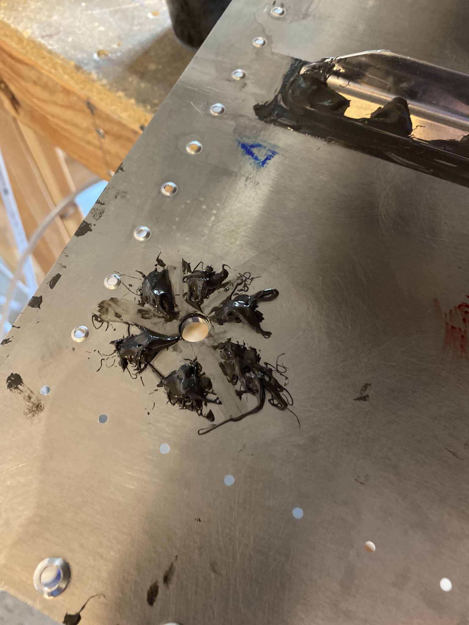
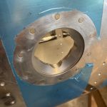
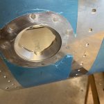
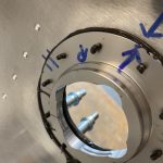
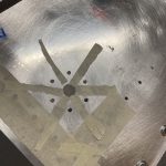
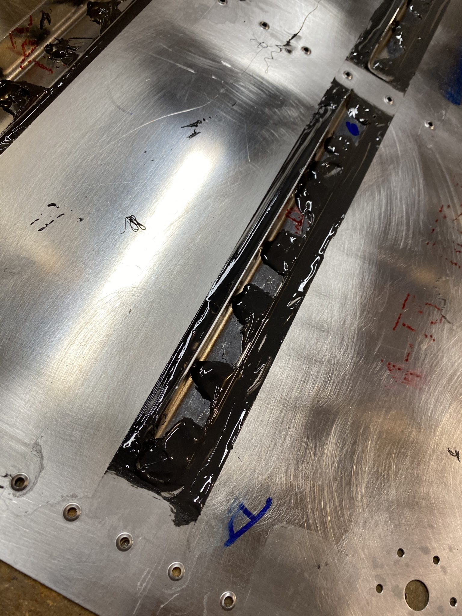
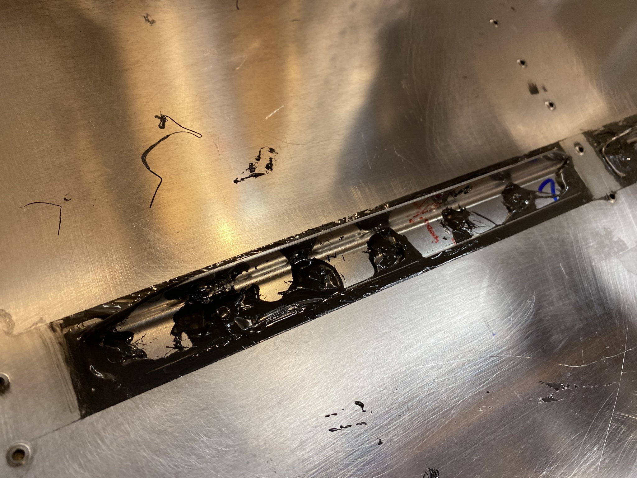
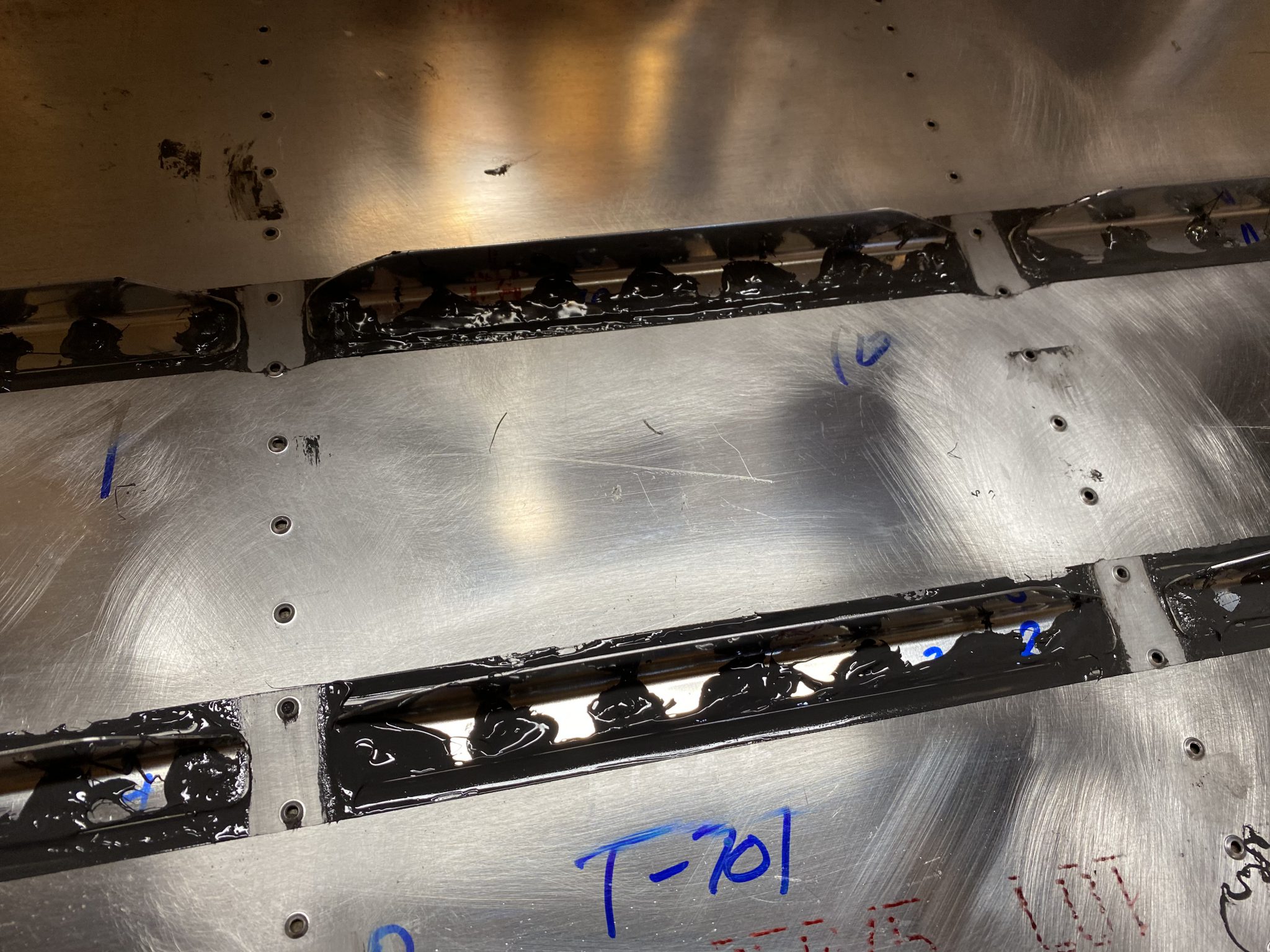
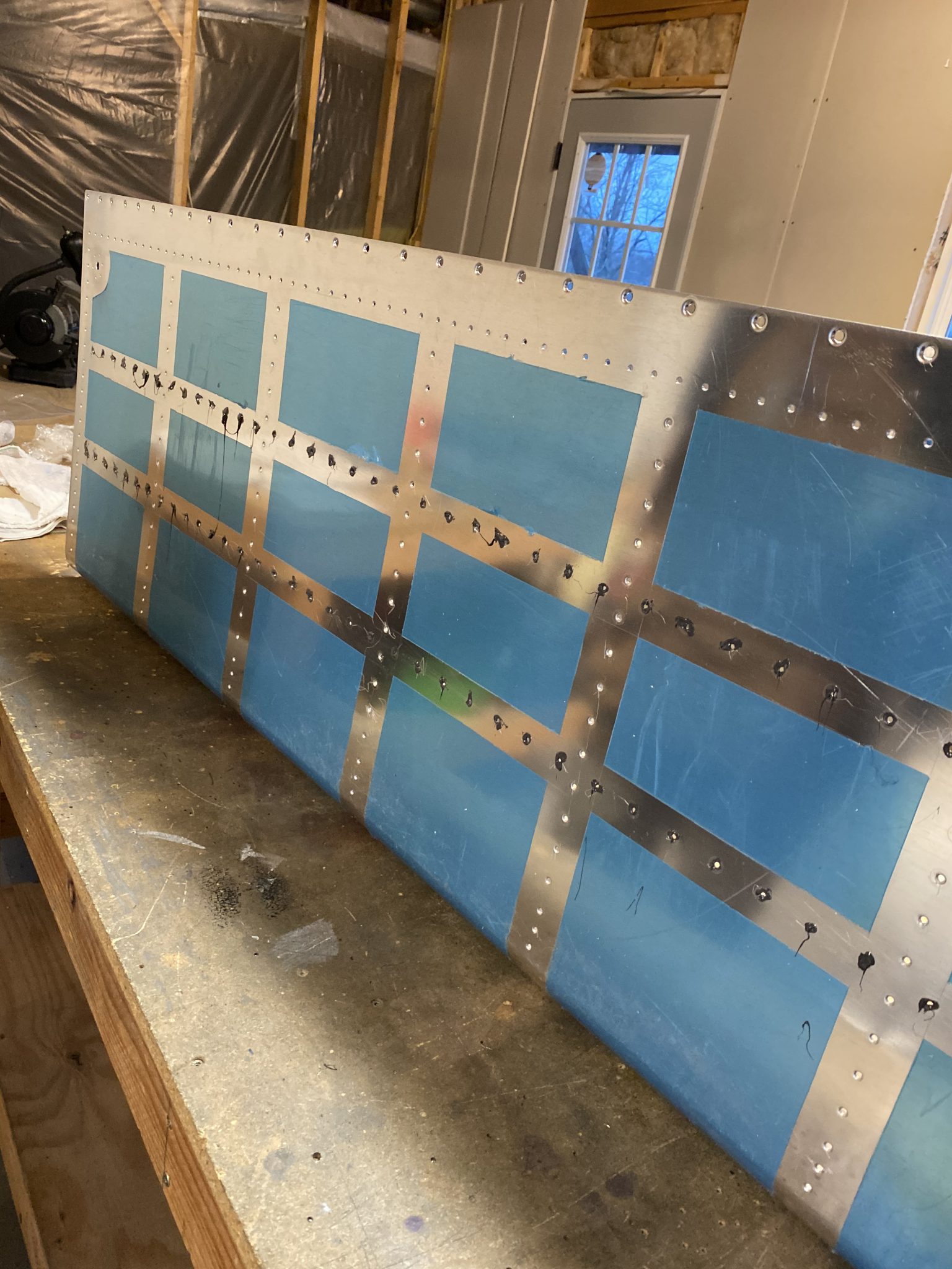
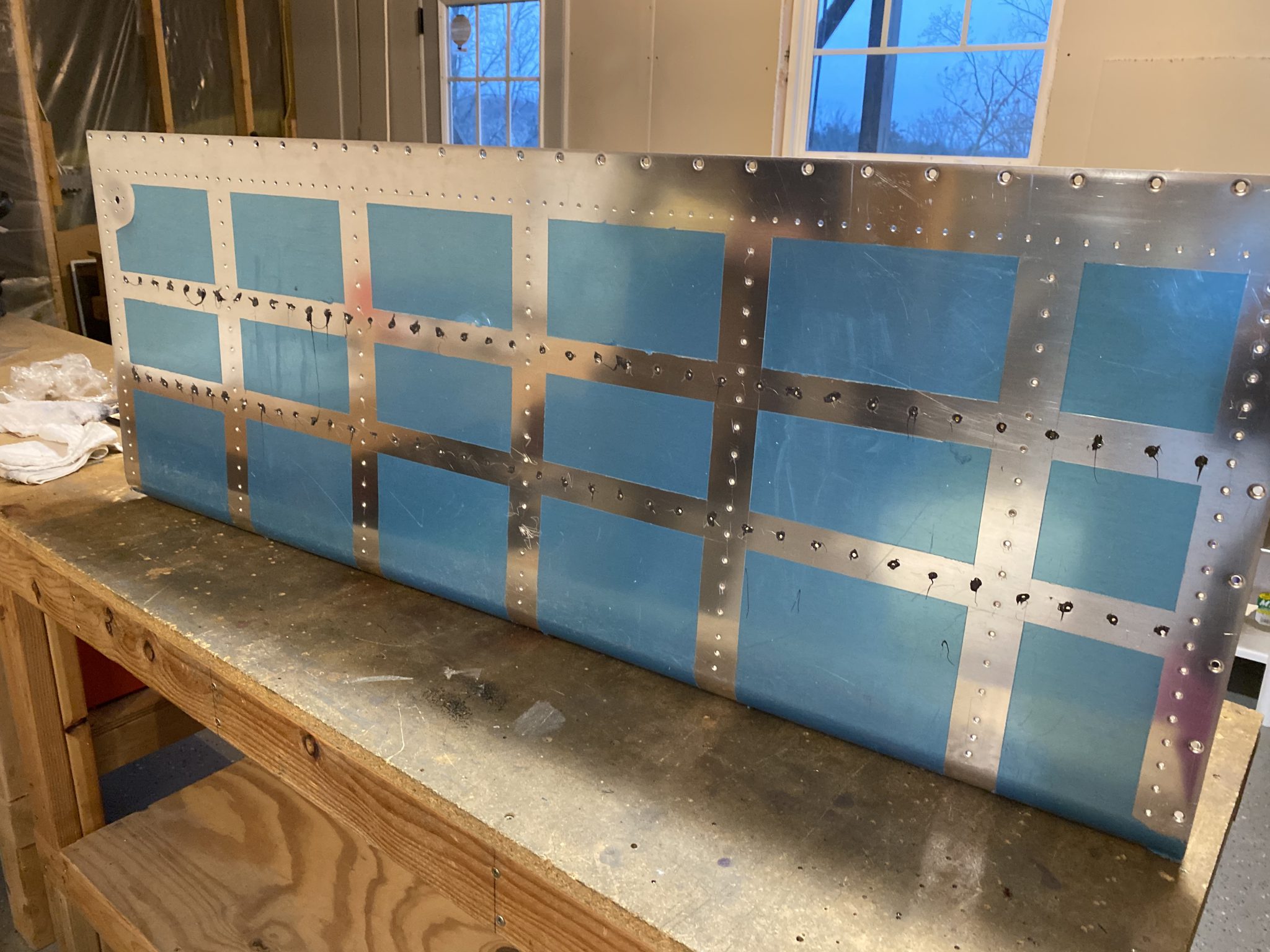
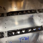
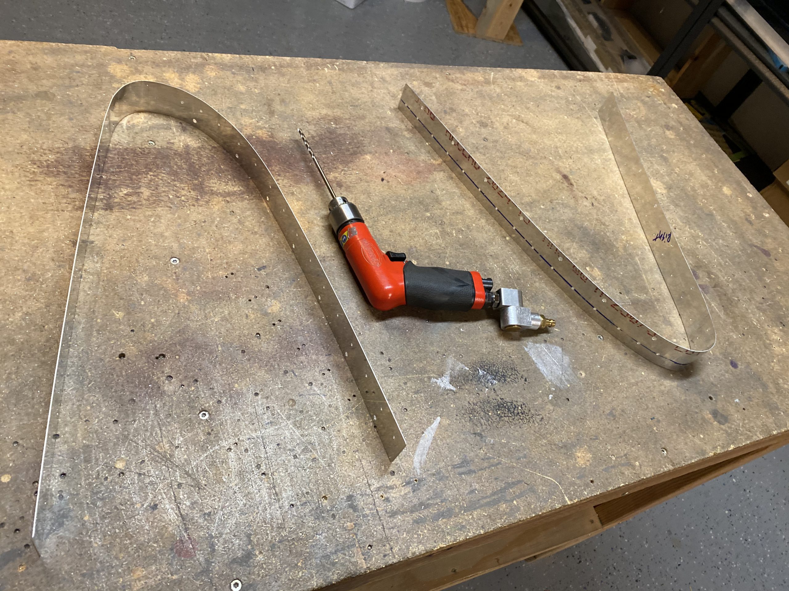
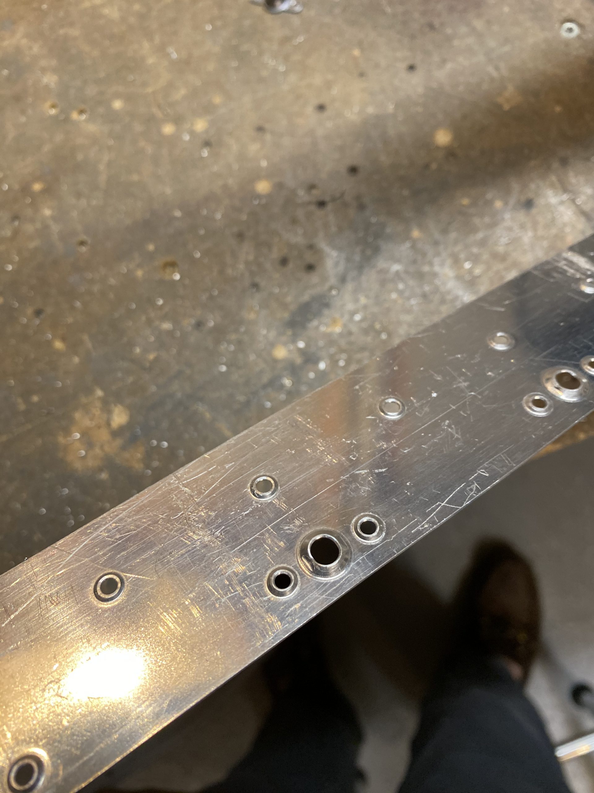
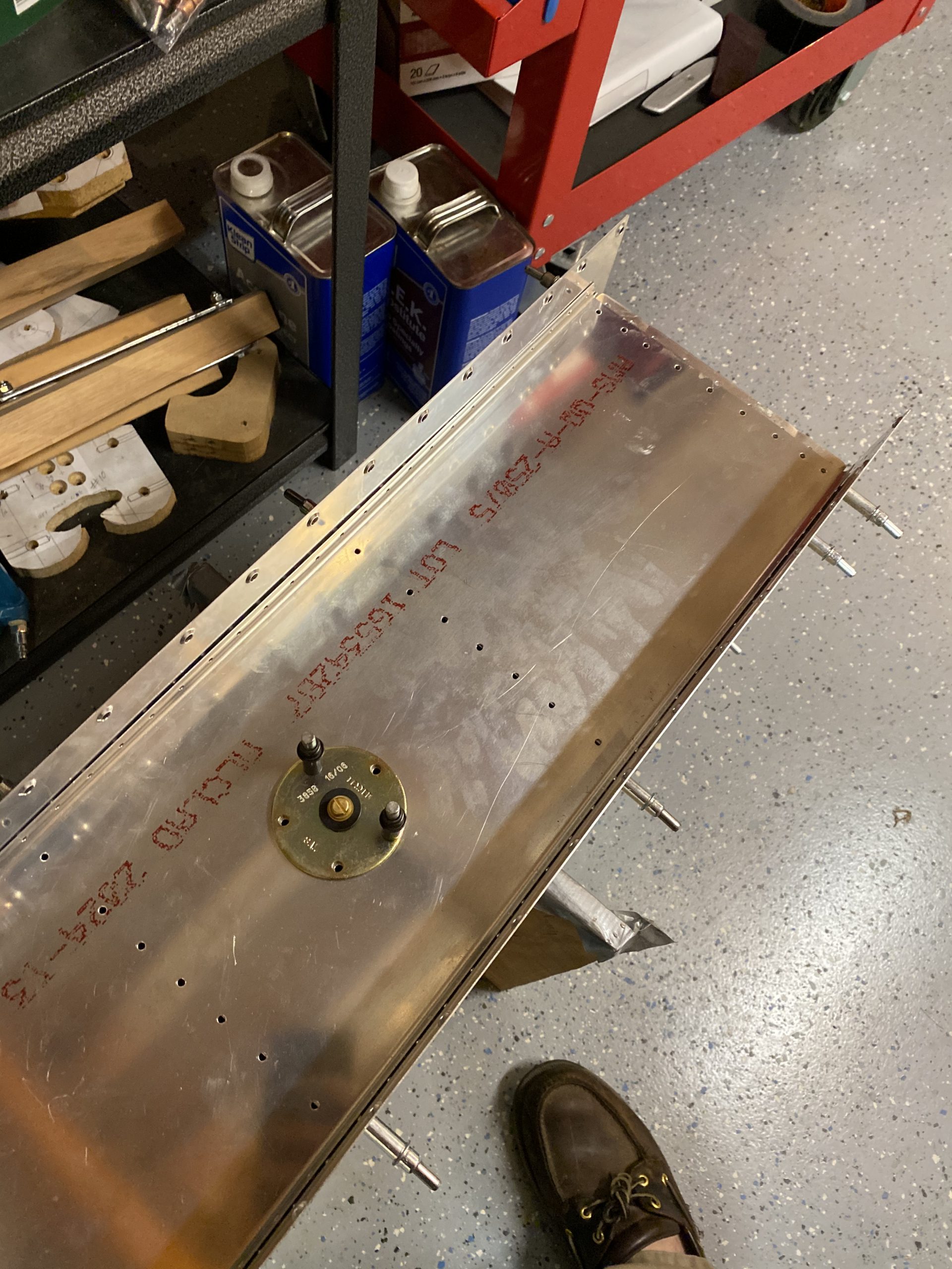
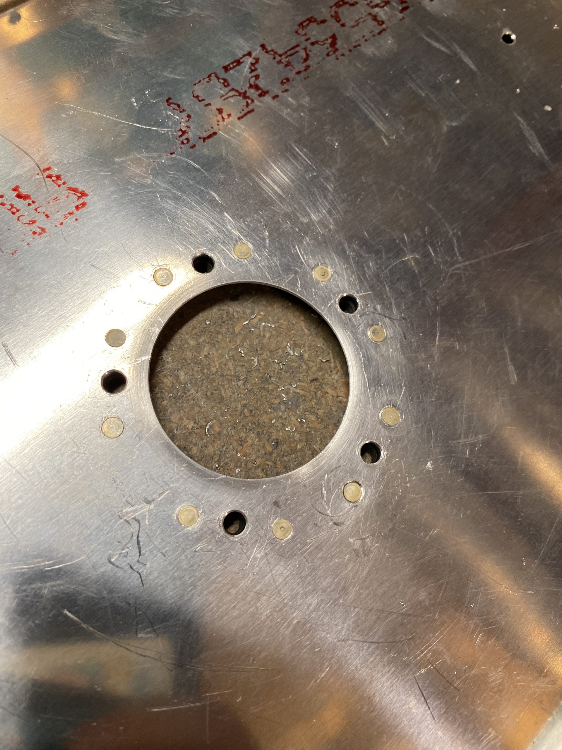
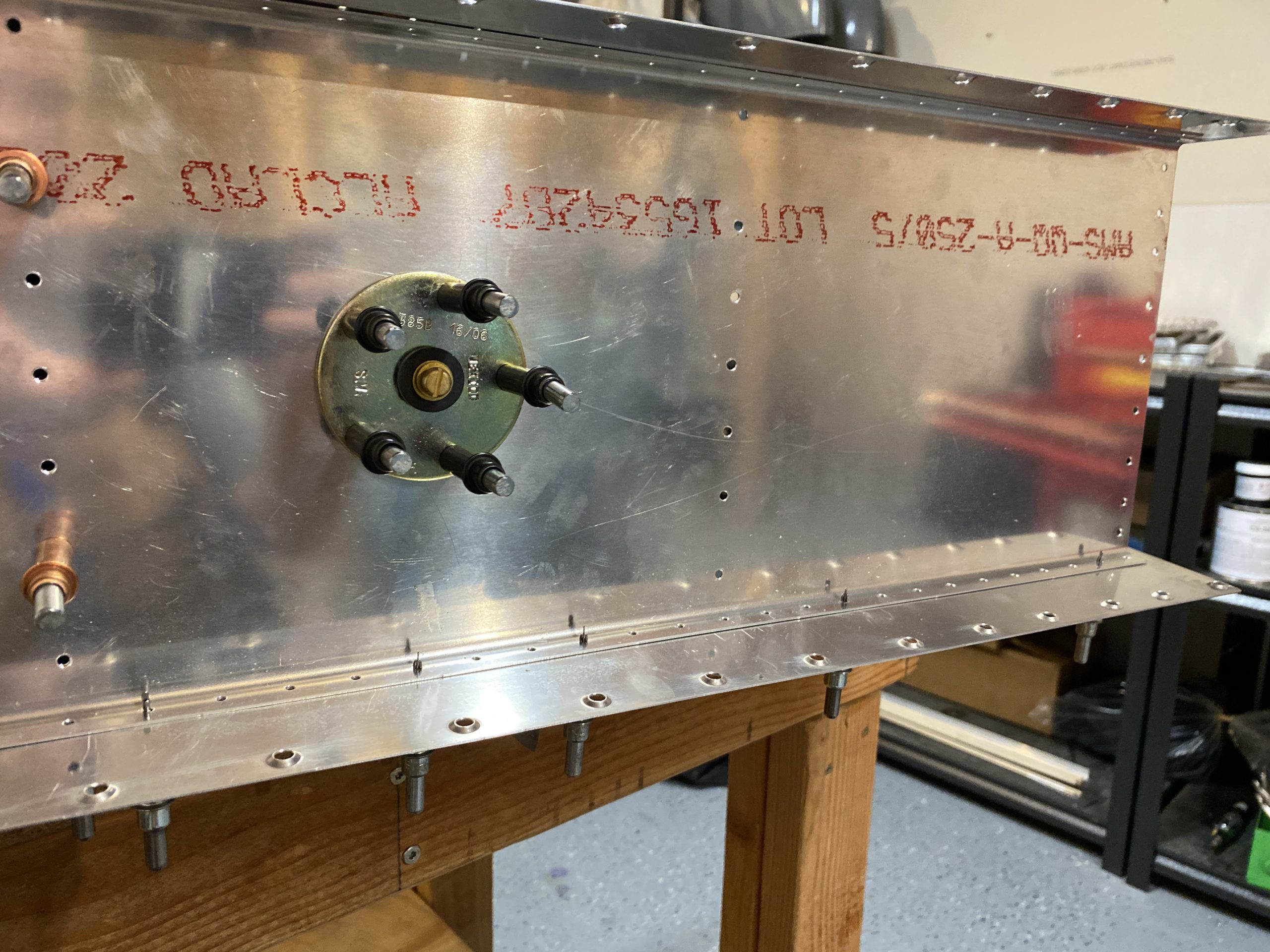
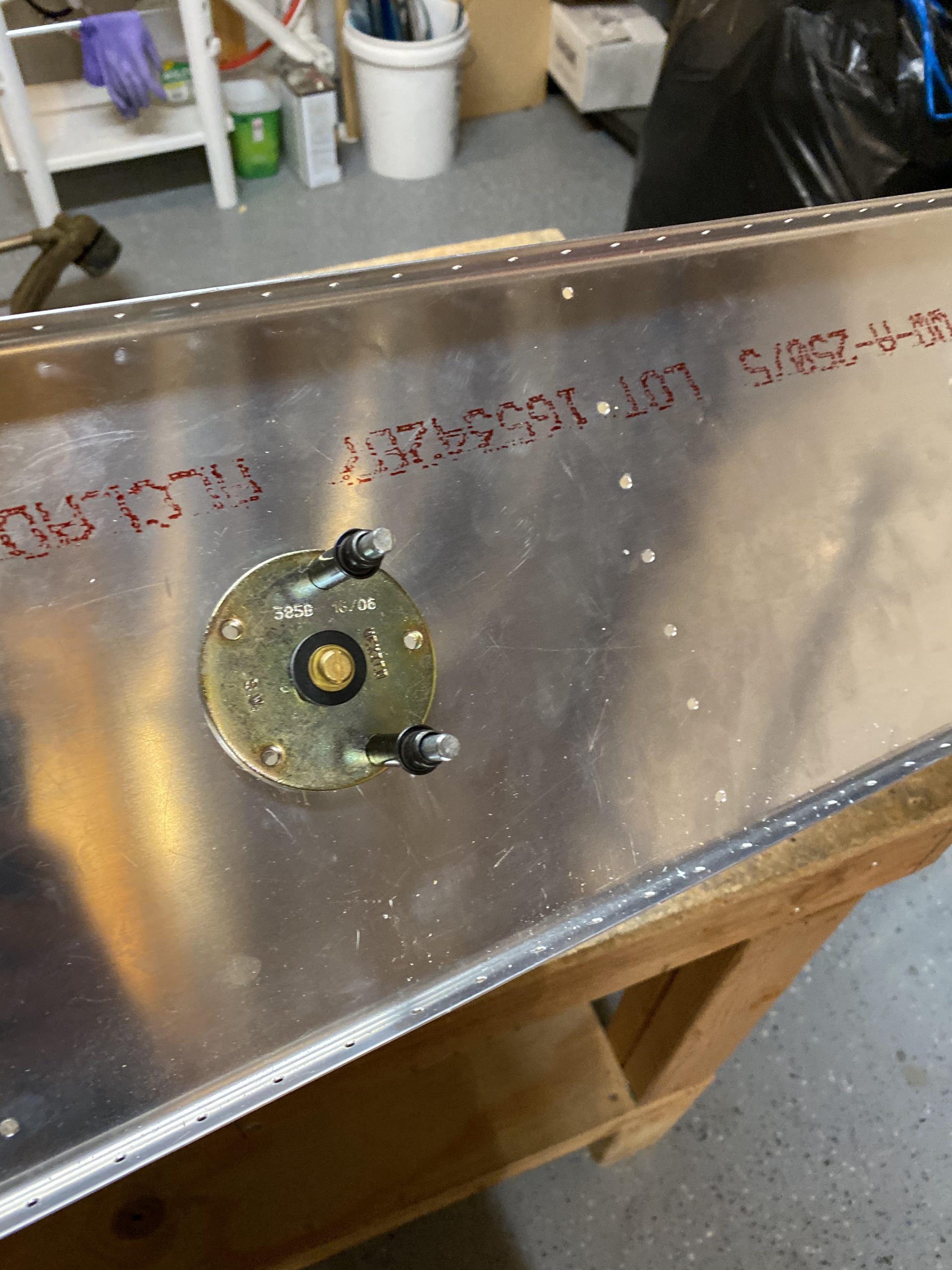
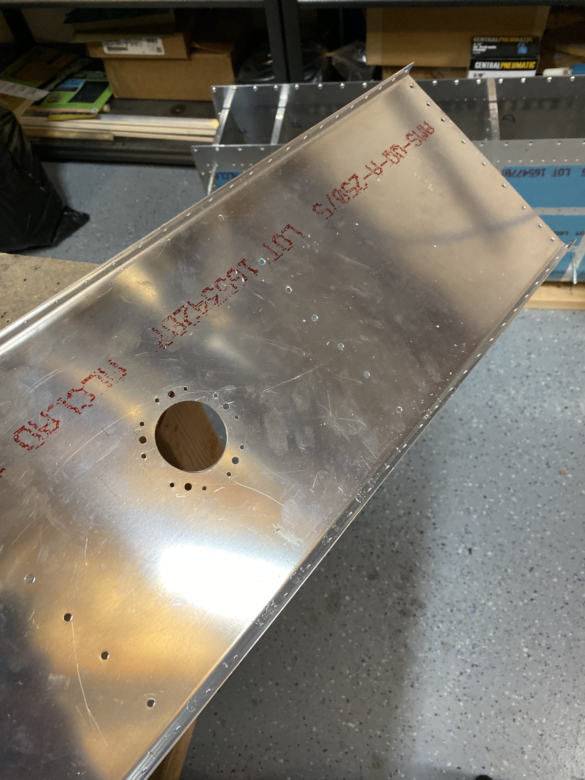
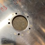
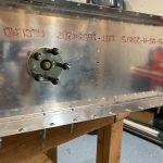
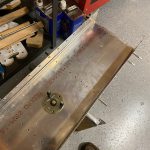
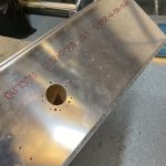
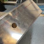
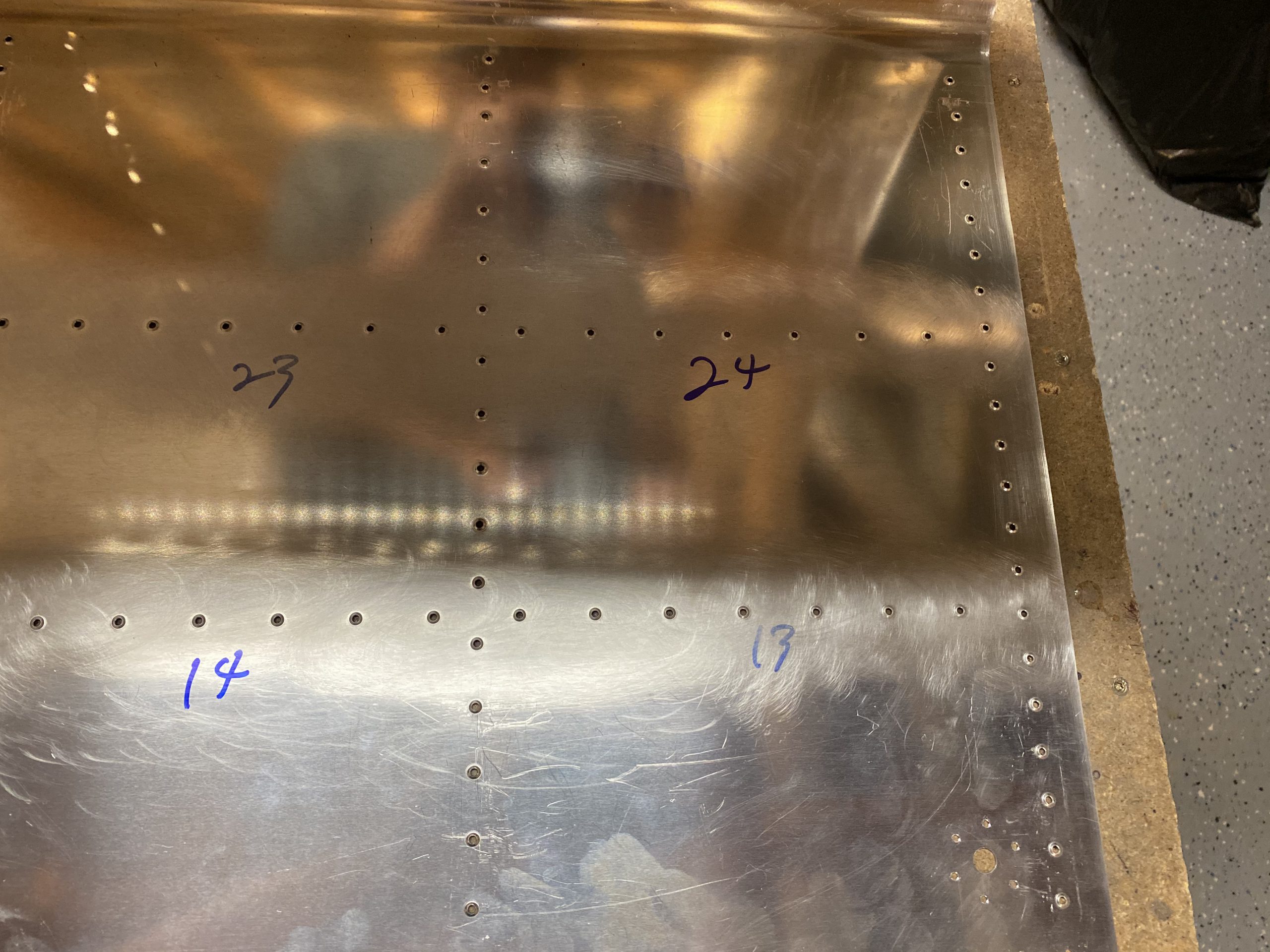
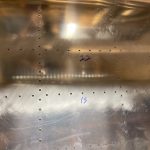
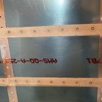
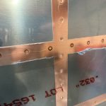
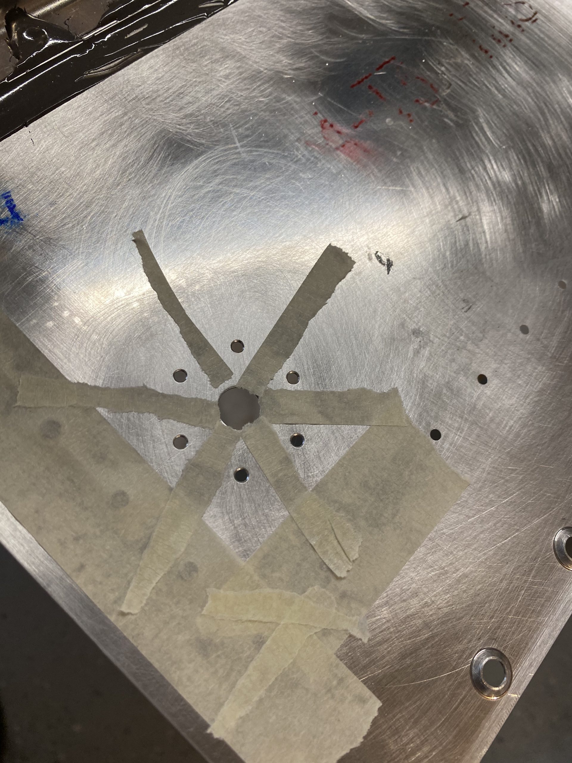
Then I grabbed the baffle and started working out where I’d install my fuel sender.  Luckily, my kit came with a now unused access cover that was pre-drilled for a sender, so I used that as a jig to gauge where it needed to be installed, as well as my drill guide. I made sure everything was clocked correctly as the sender has a certain way it needs to be installed. The photos below show where I ultimately decided it should be installed.  I also used the right tank to measure the distance from the bottom of the tank to the bottom of the access plate to make sure I had this sender going in the right spot vertically on the baffle.  Then I clamped it down with some C-clamps and drilled.


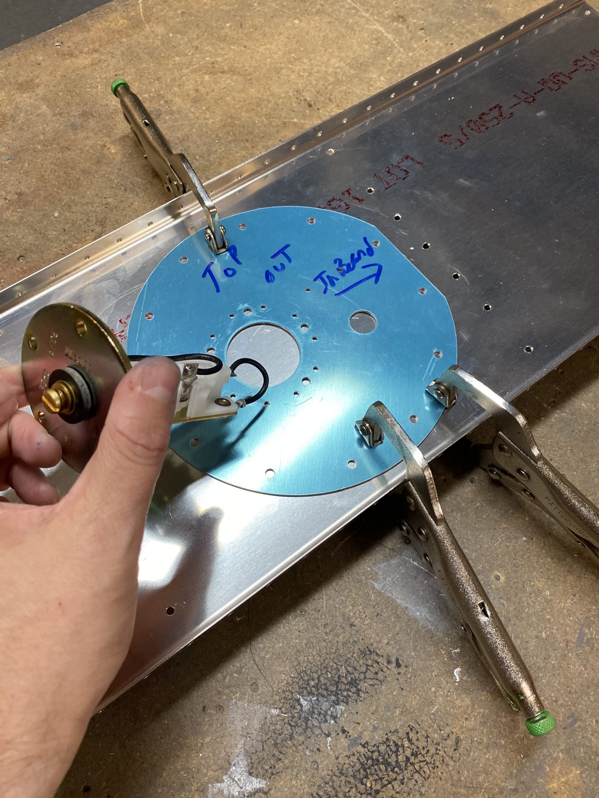
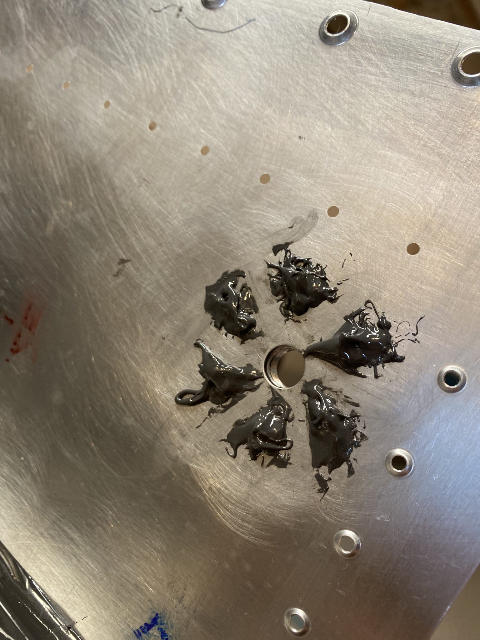
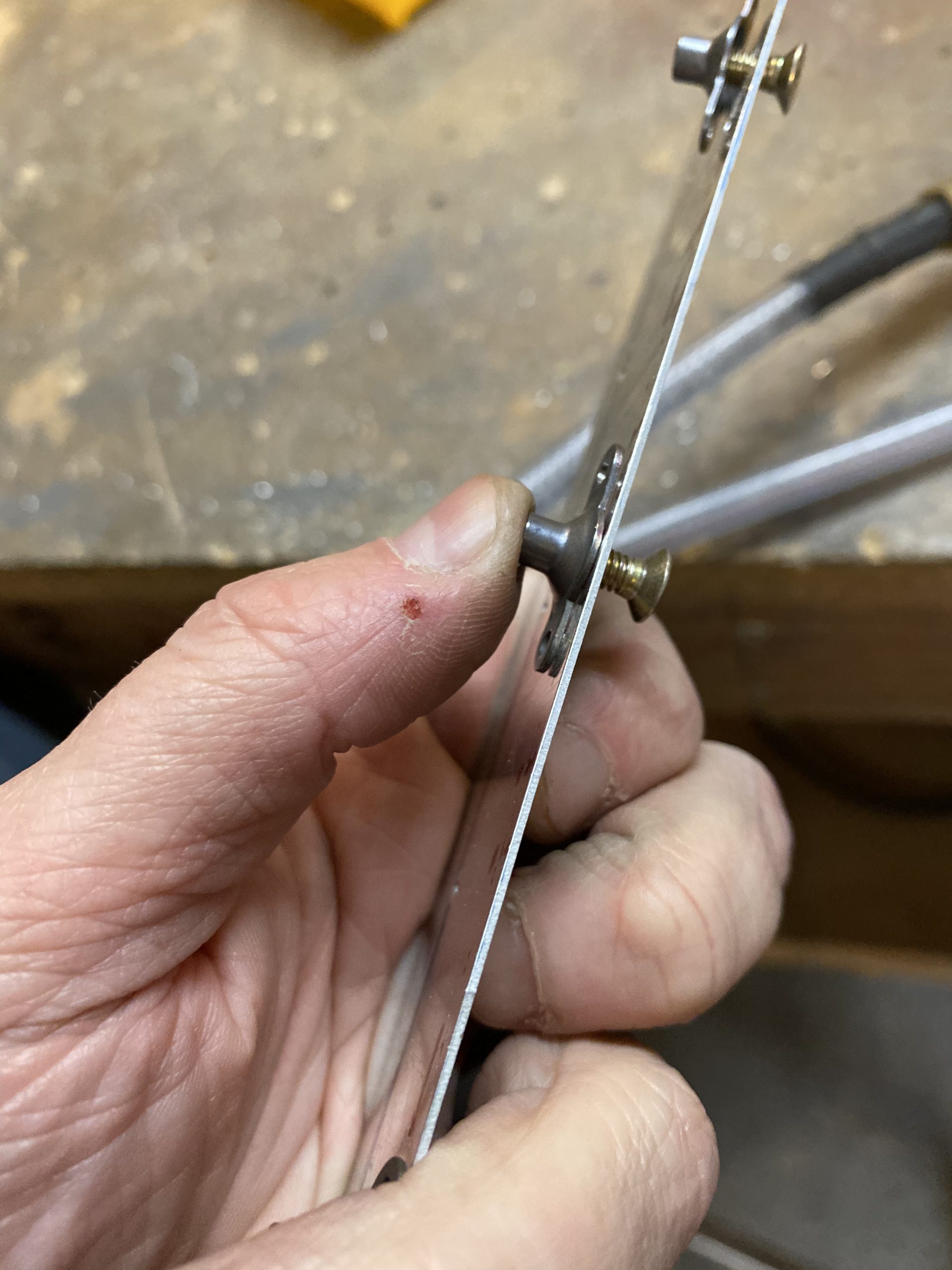
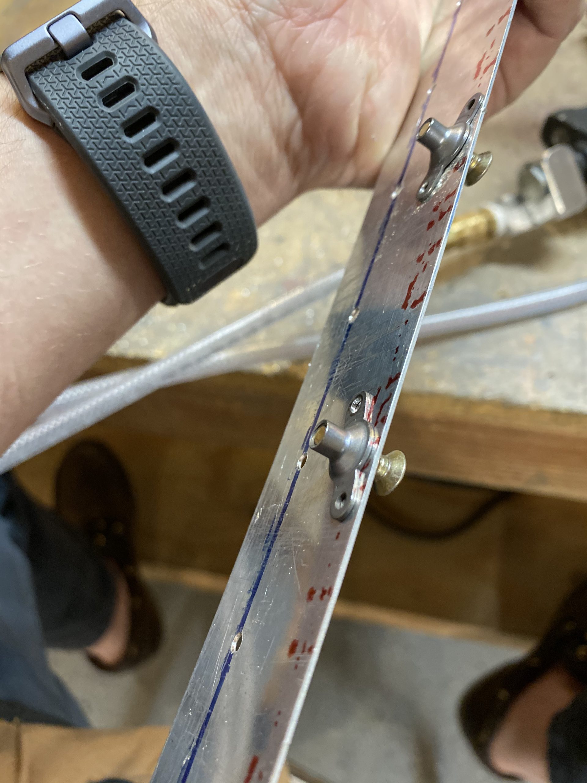
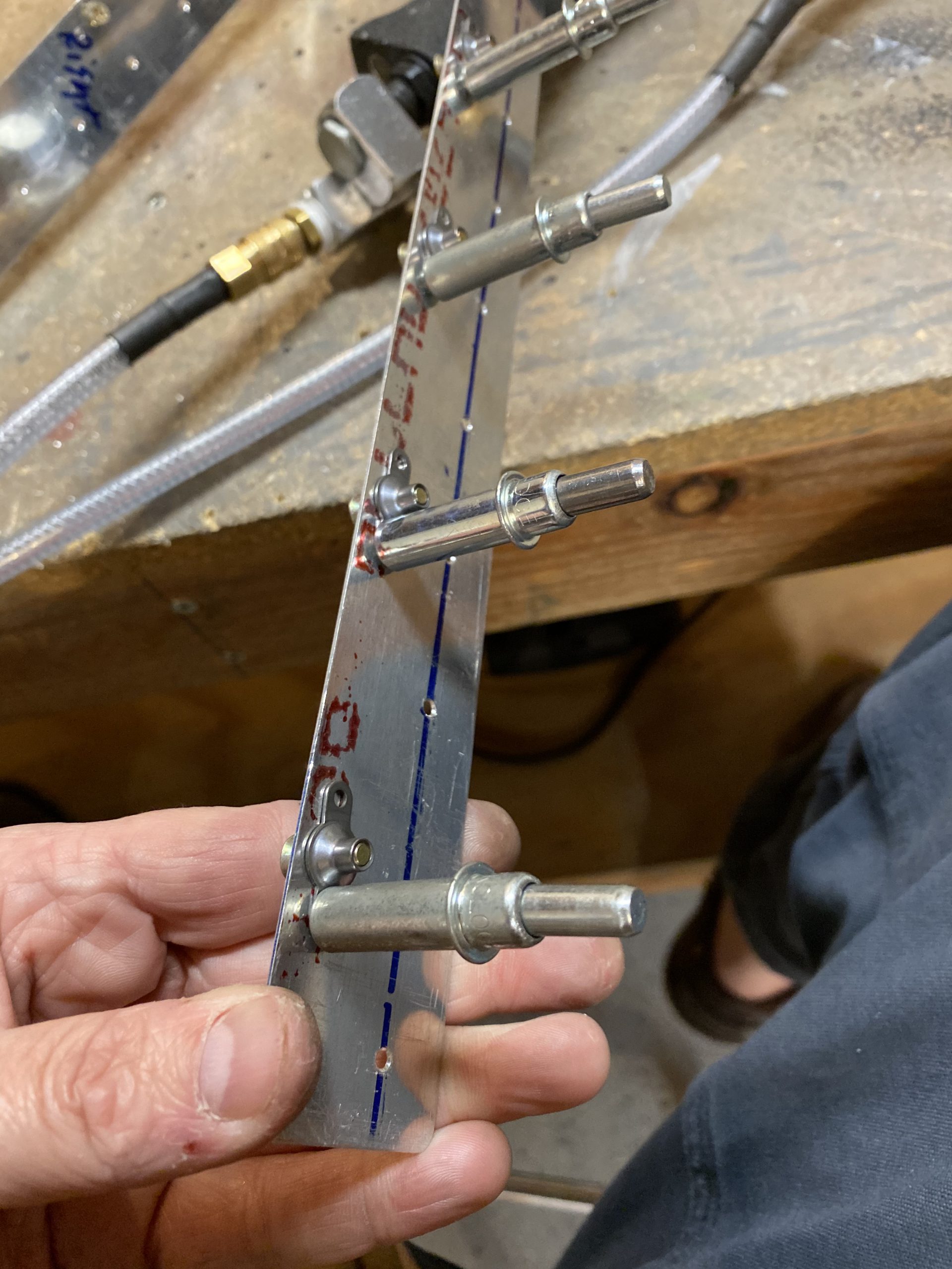
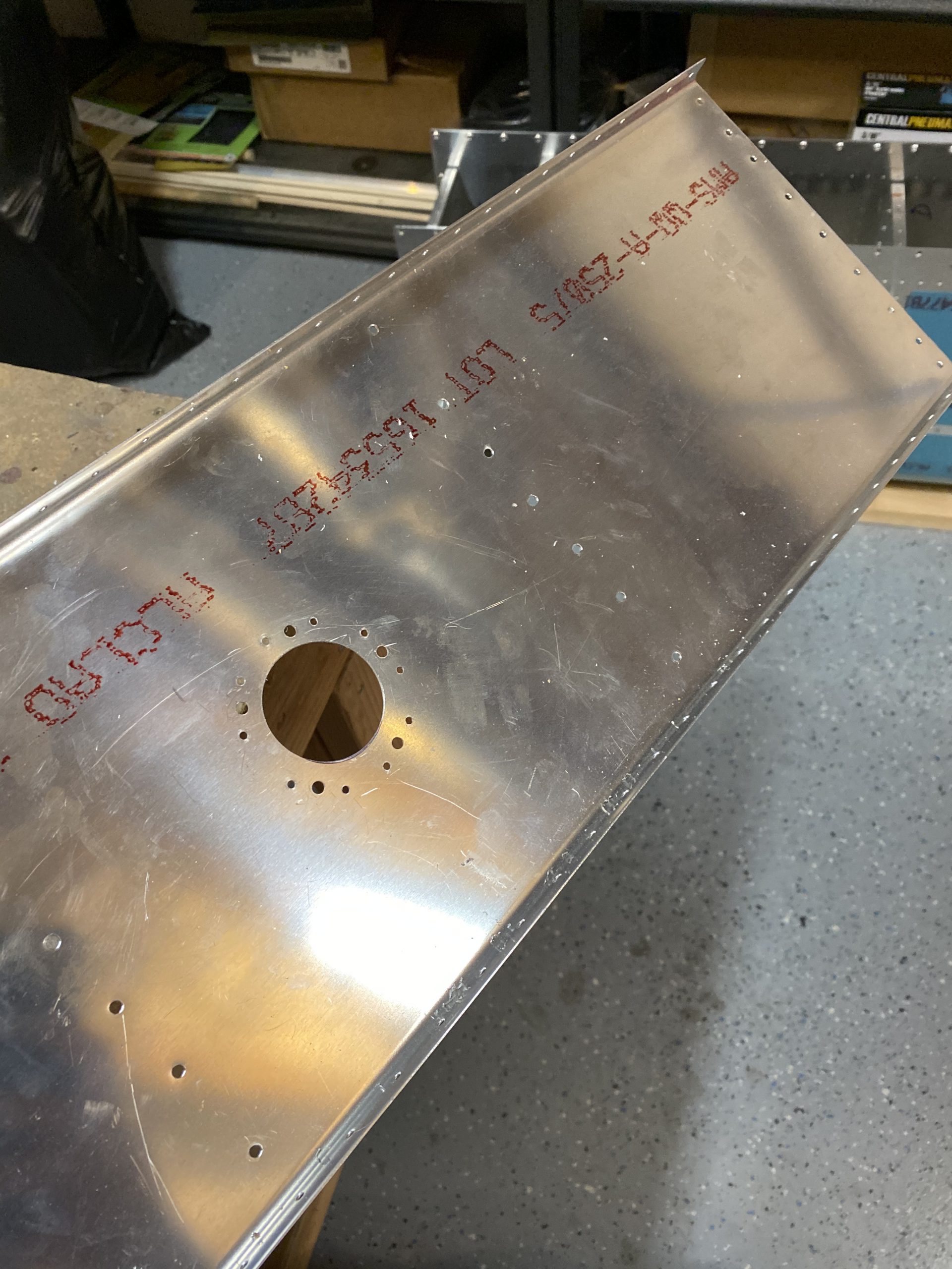
I used the holes in the access plate as my drill guide to drill the #40 holes for the K1000-8 nutplates, and then the larger screw holes were drilled with a #19 drill bit to fit the screws.  I also outlined the hole for the sender with a sharpie. I’ll need to cut this out.

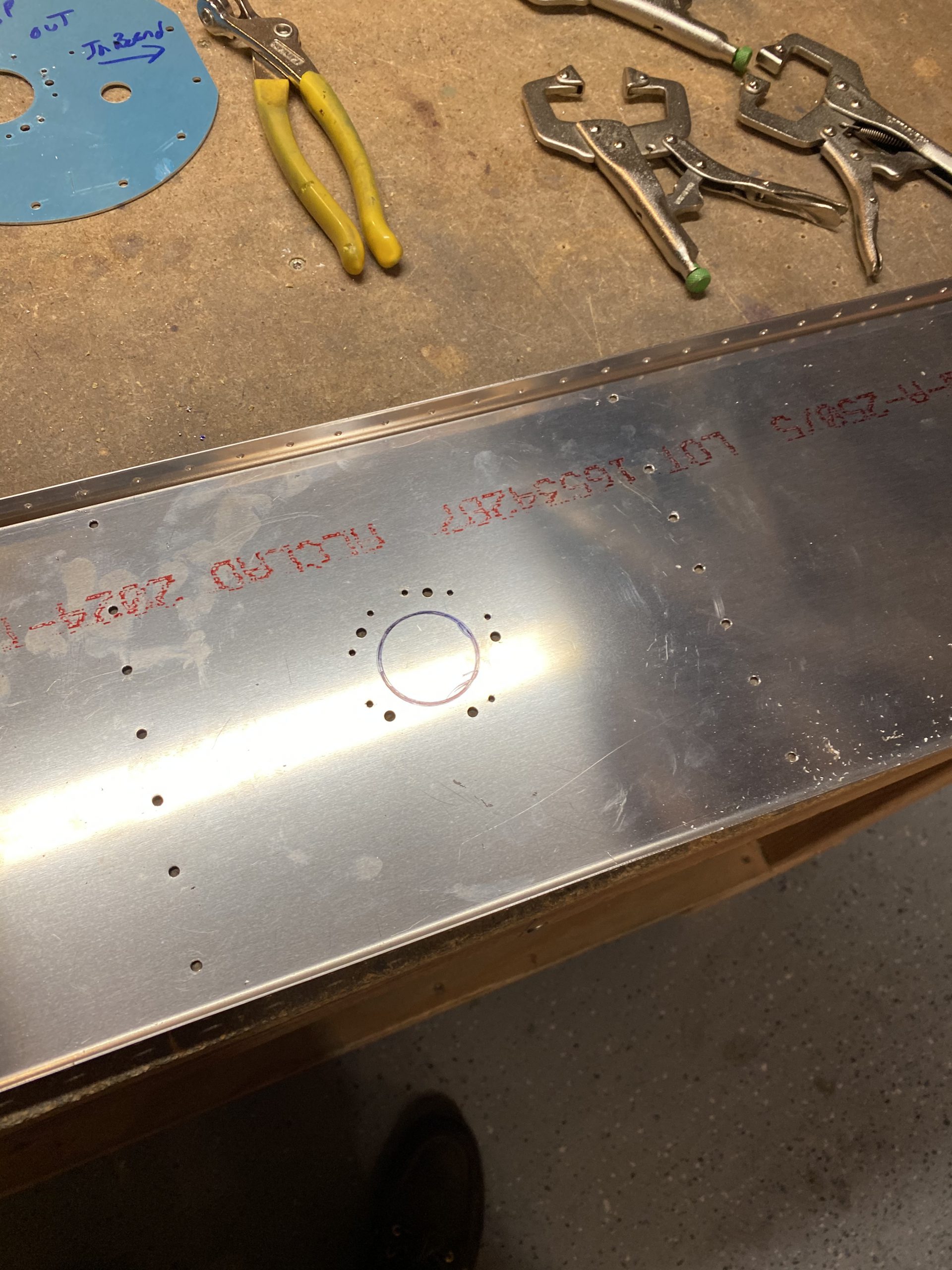
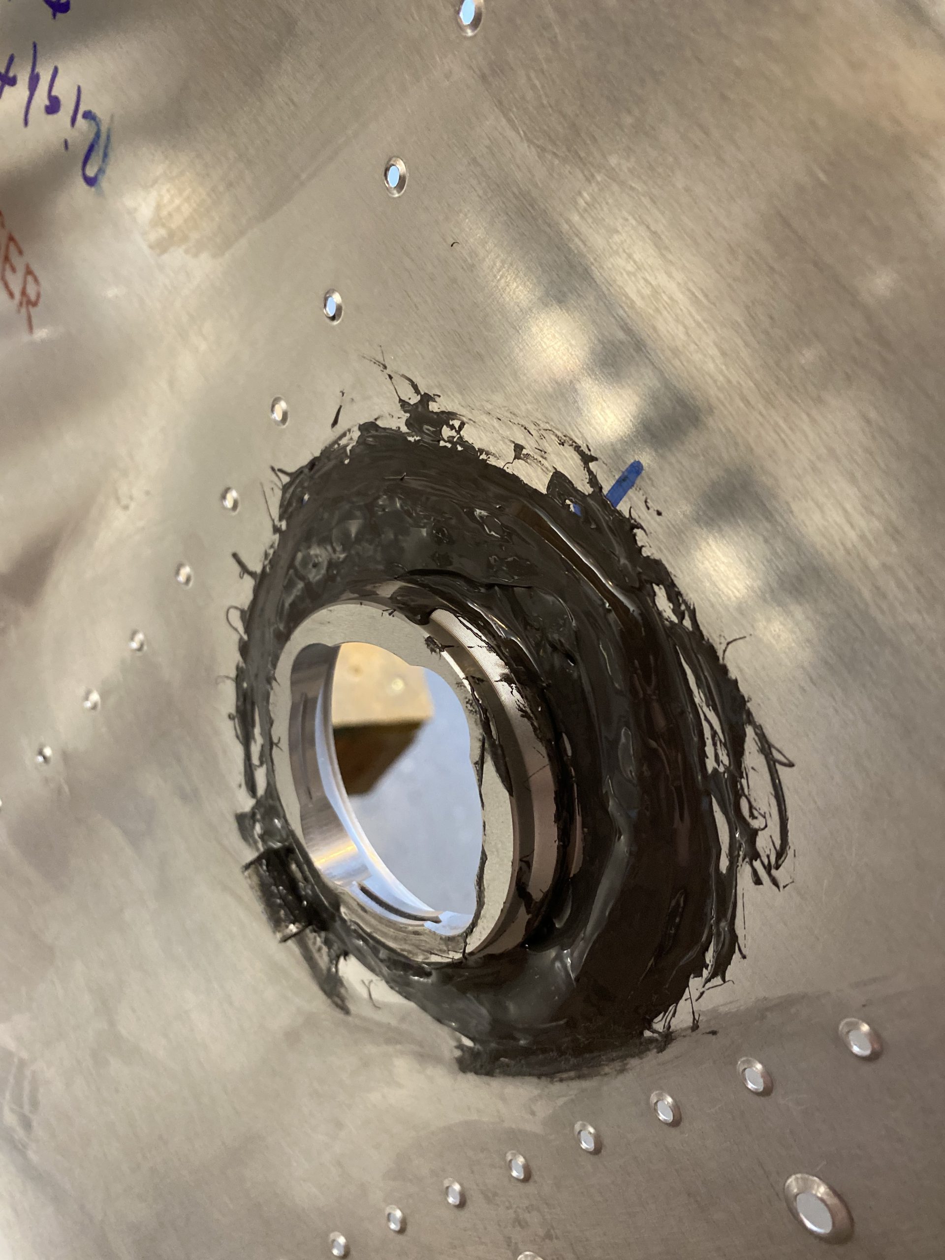
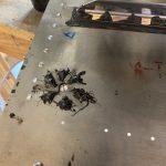
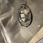
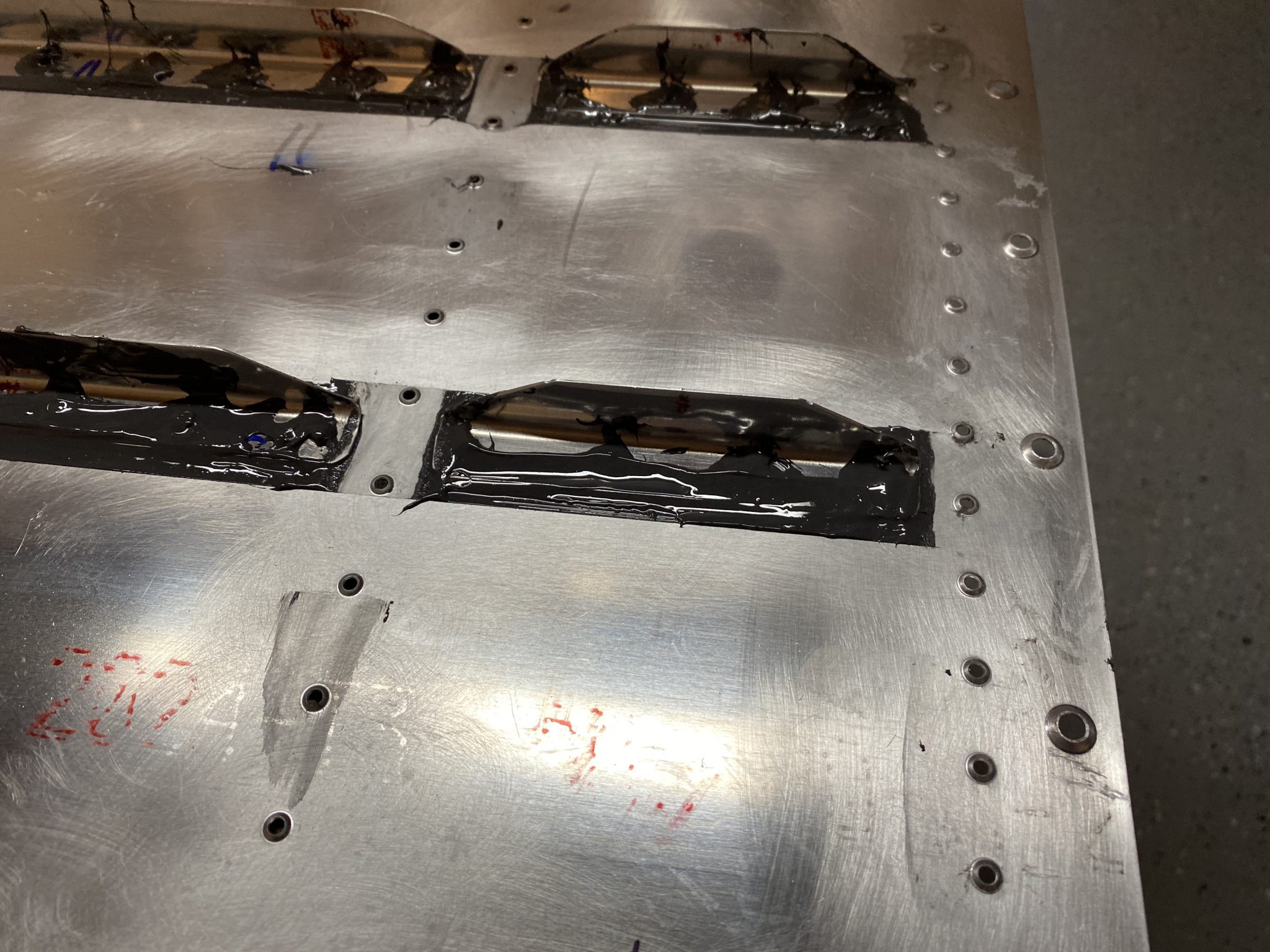
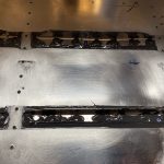
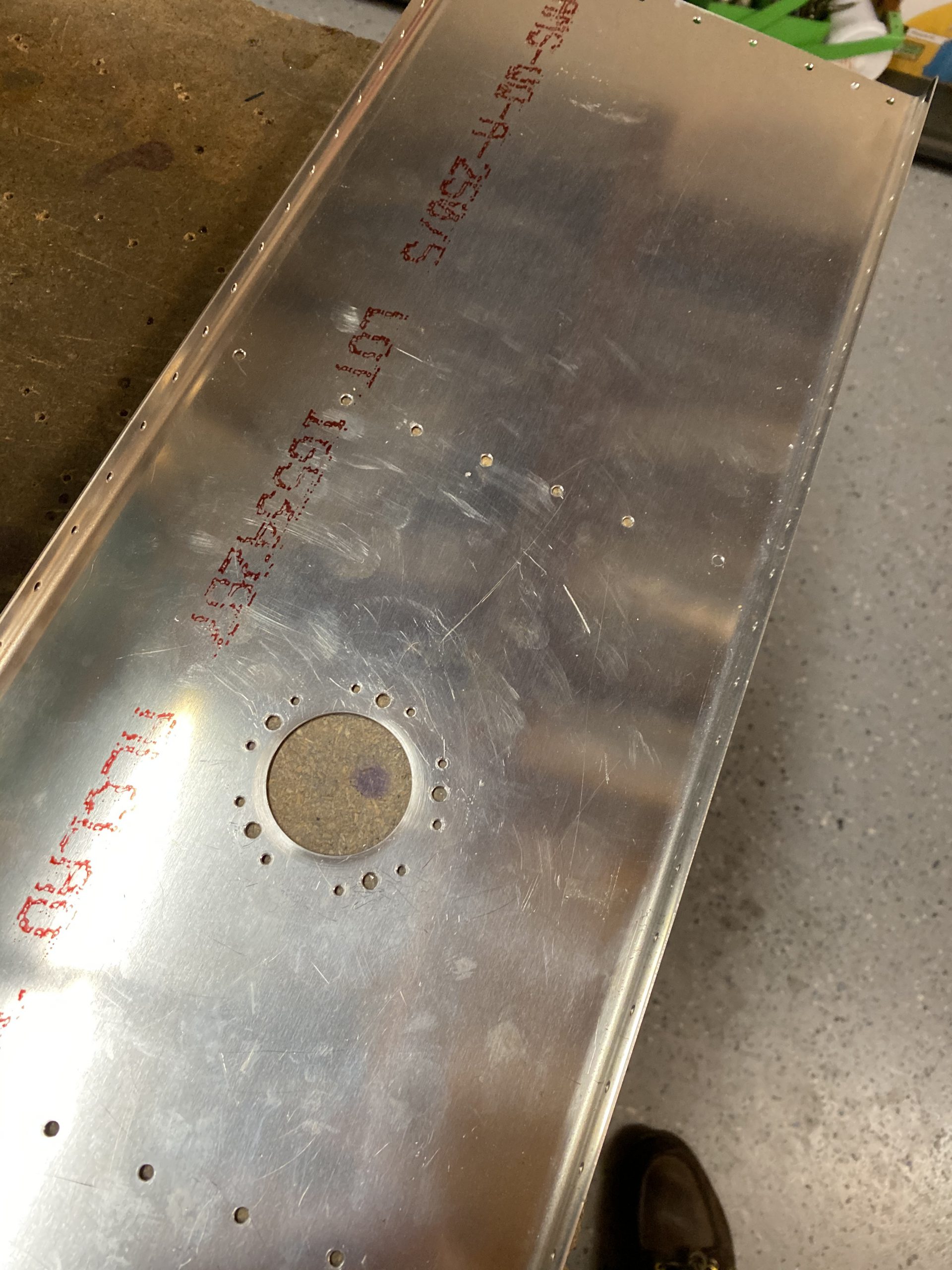
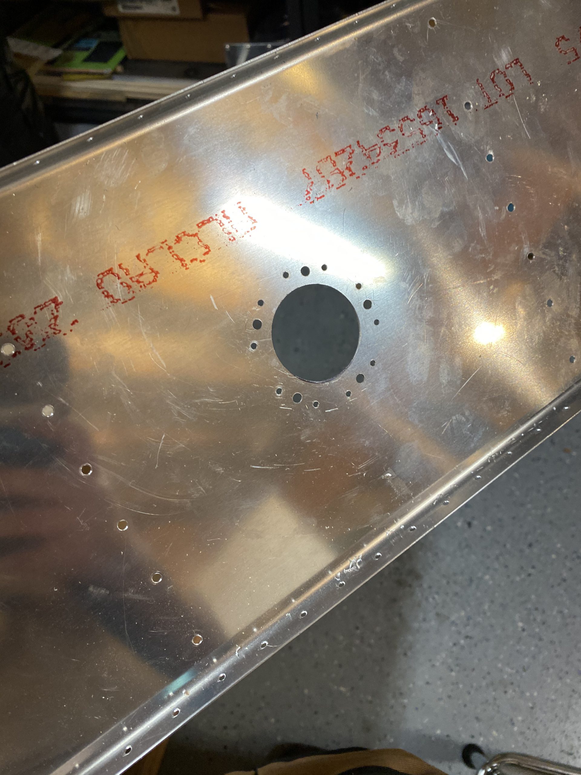
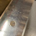
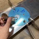
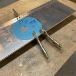
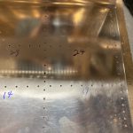
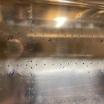
Then it was over to the drill press where I chucked up my fly-cutter and got everything centered up and the fly cutter adjusted to cut just to the outside of my sharpie outline.  GO SLOW!! Set your drill press to a slow speed and use light pressure when using a fly cutter.  That seemed to work really well for me, and gave me a nice round and smooth hole!

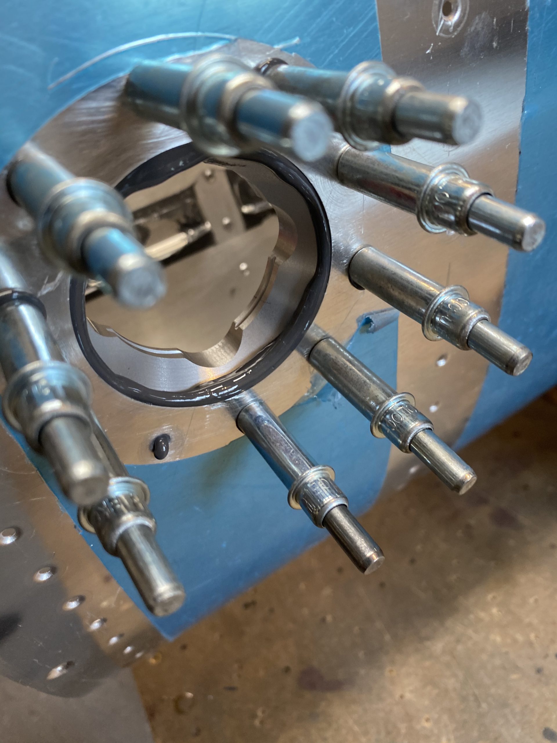
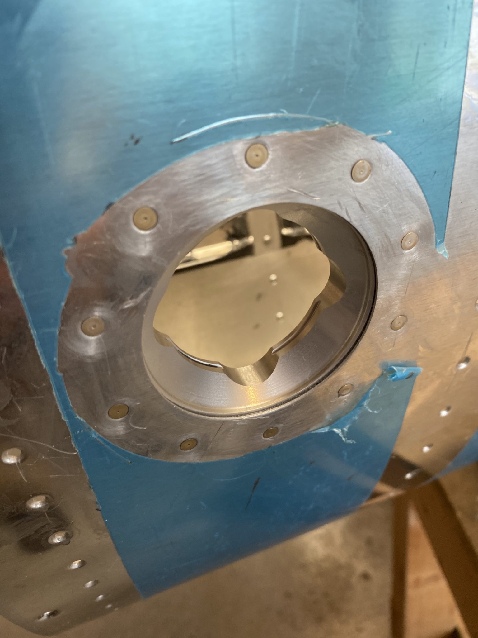
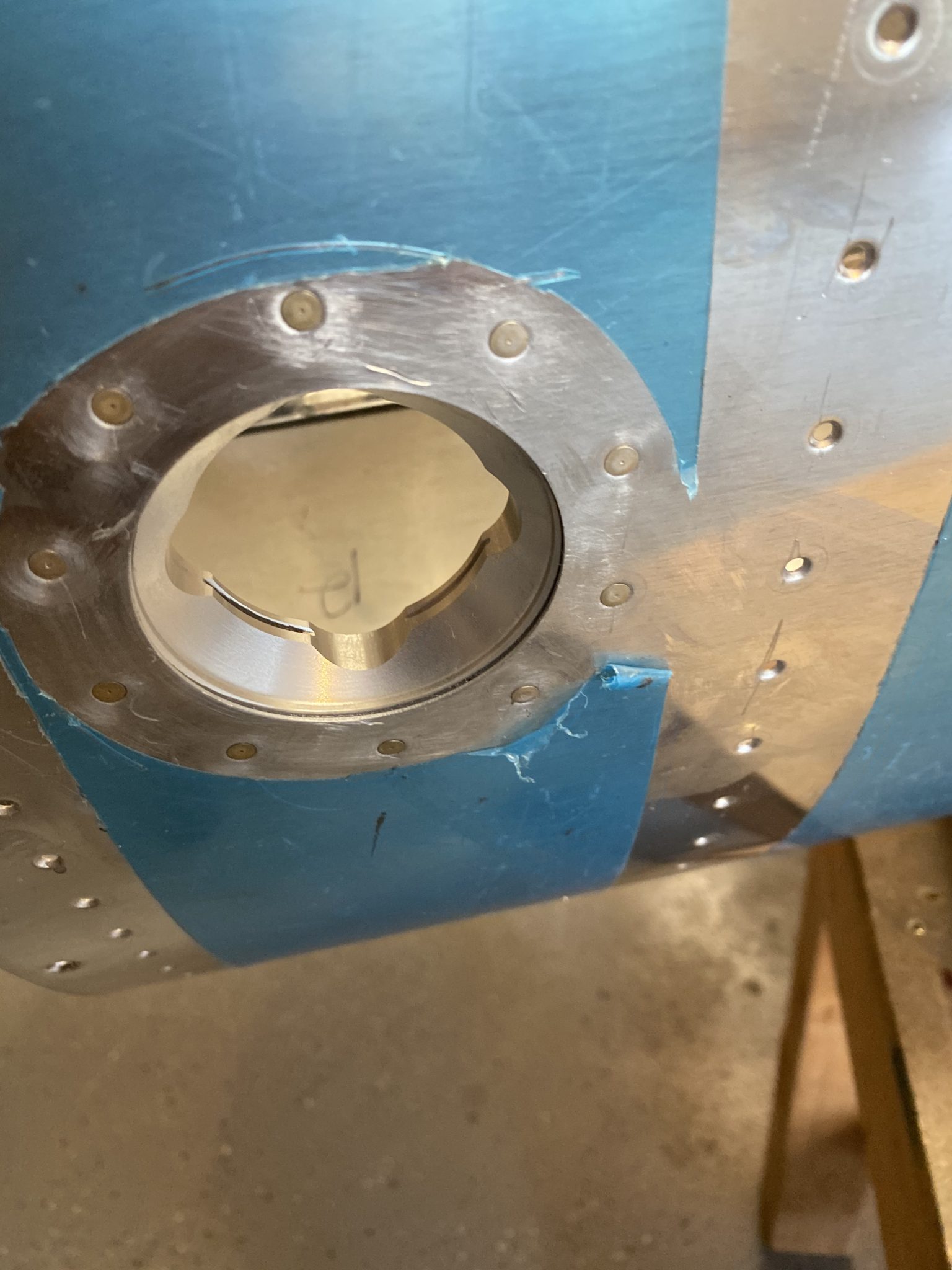
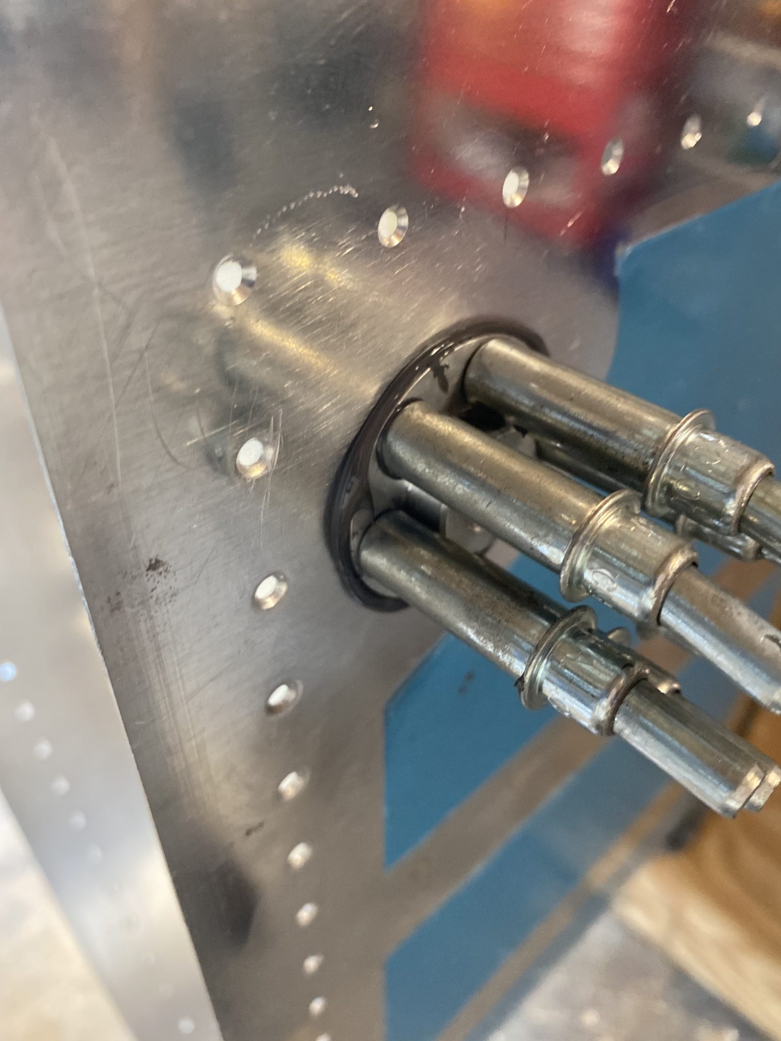
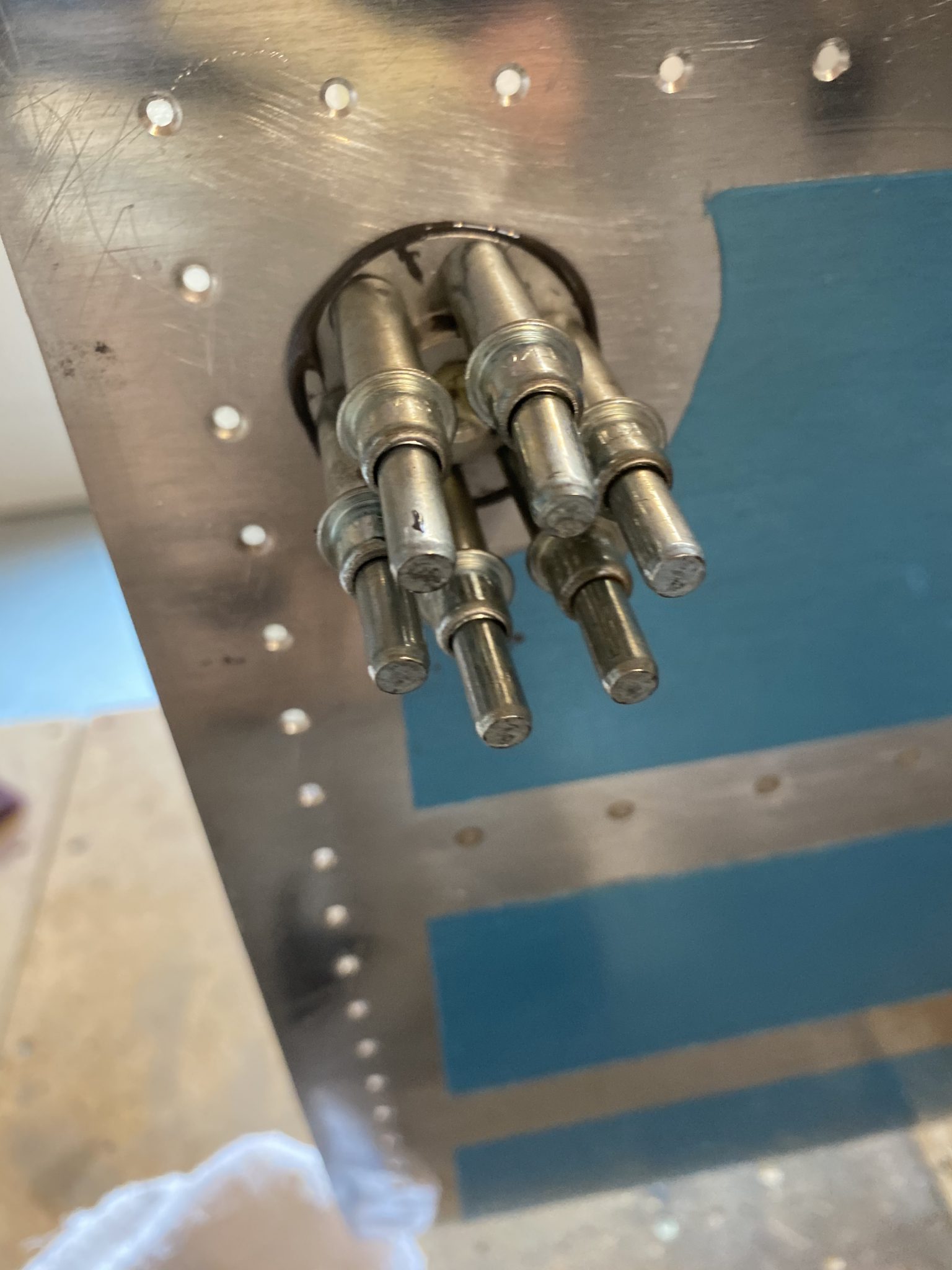
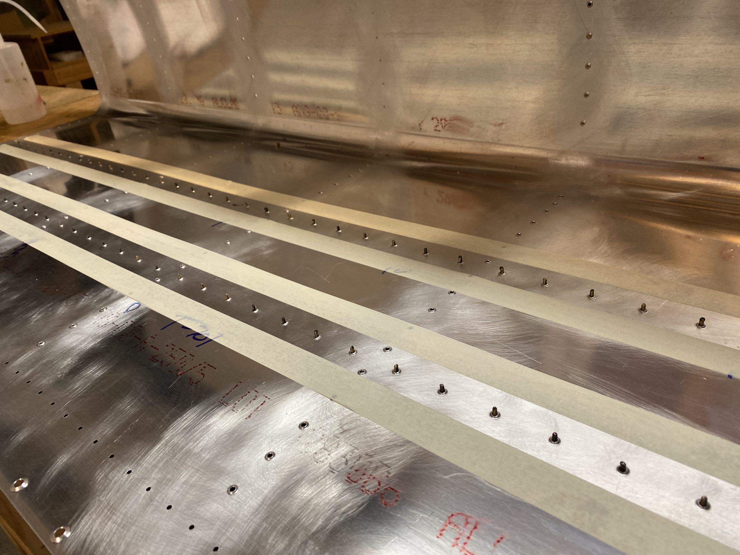
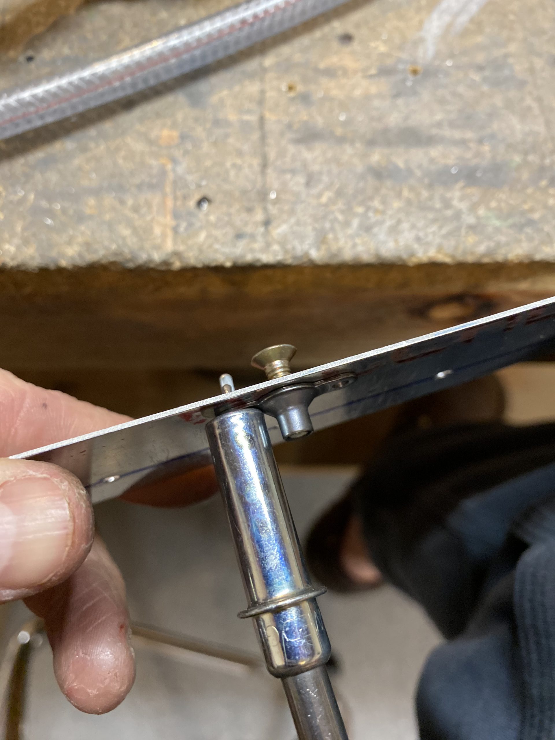
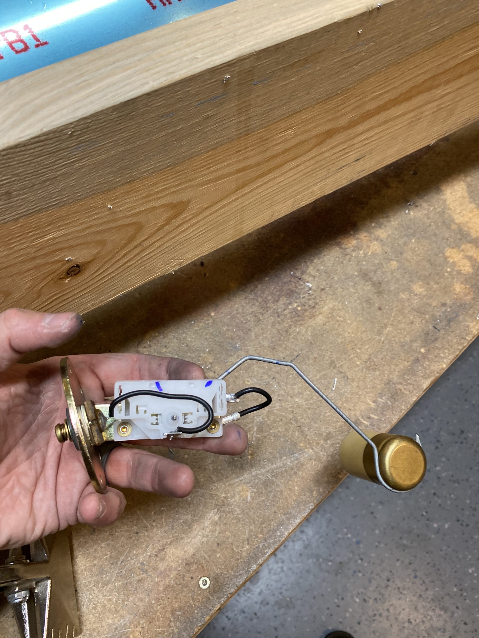
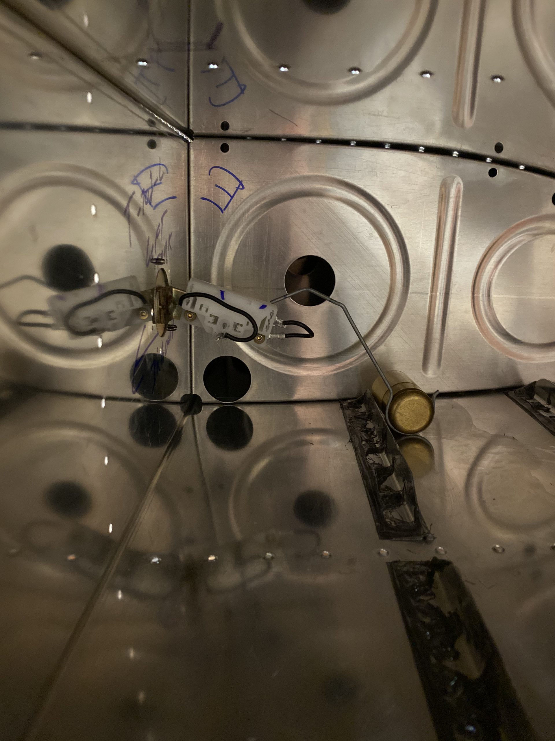
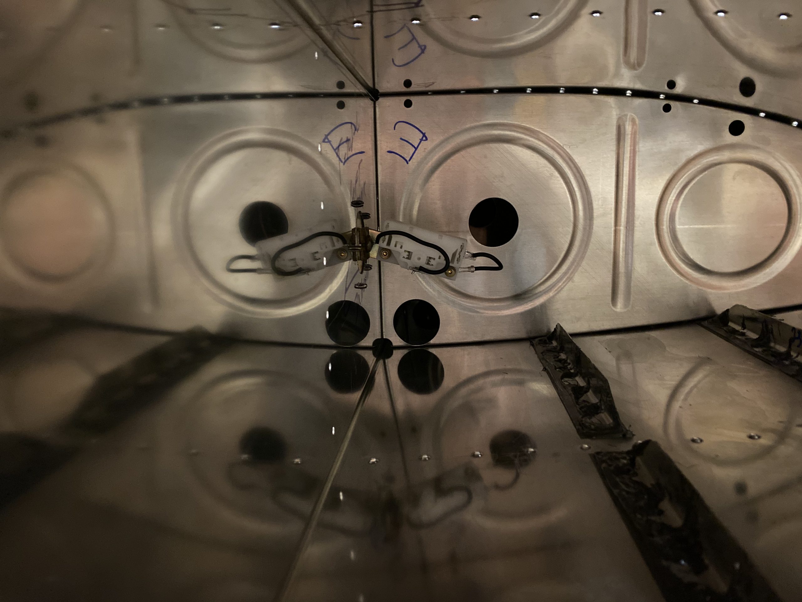
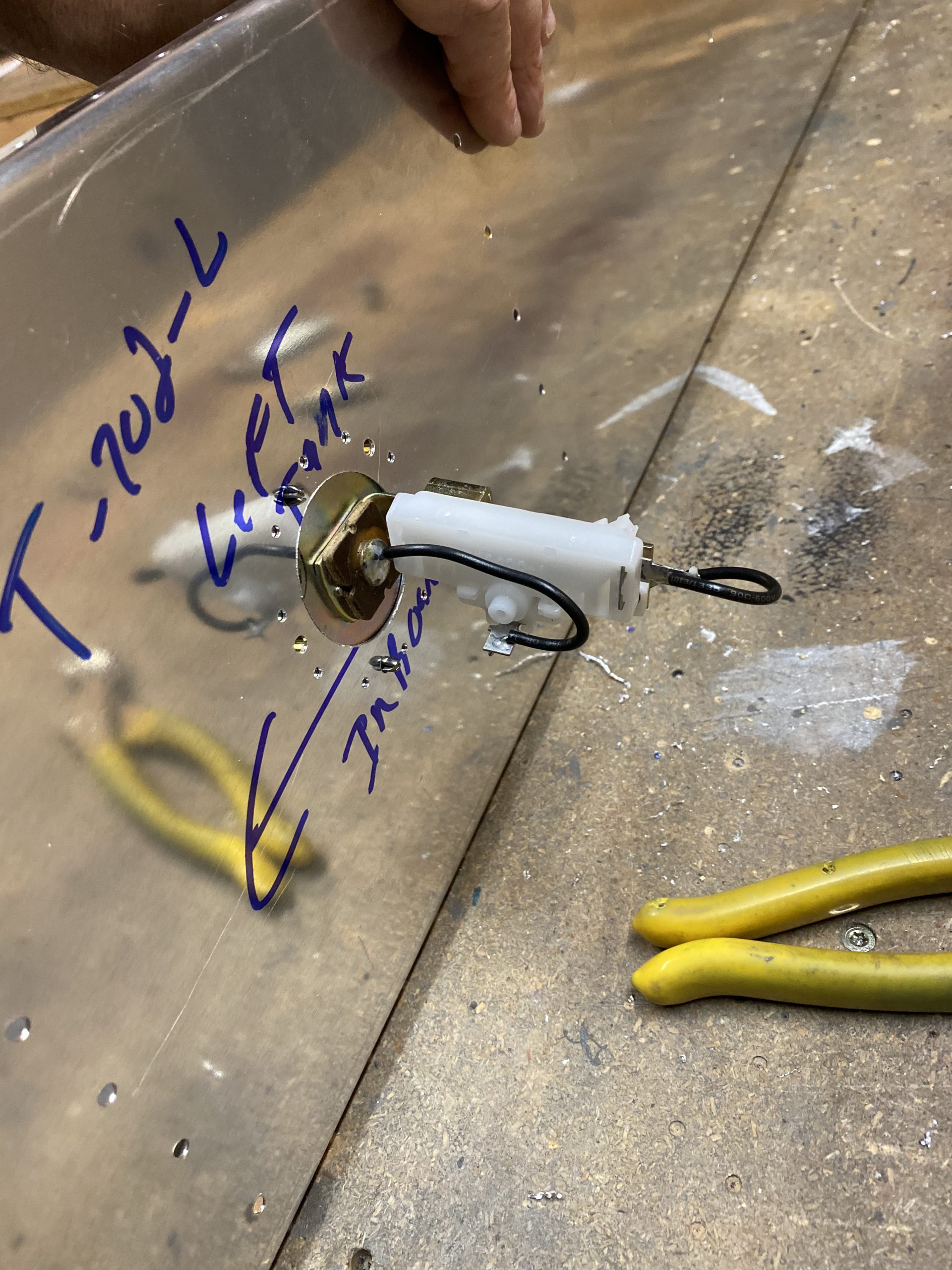
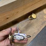
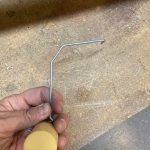
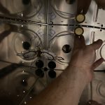
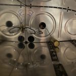
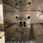
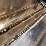
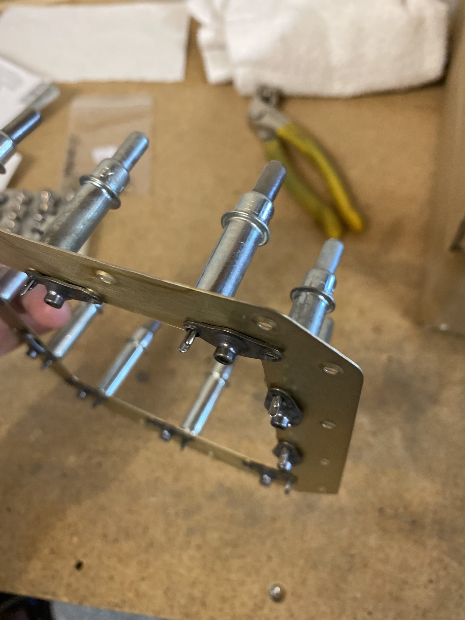
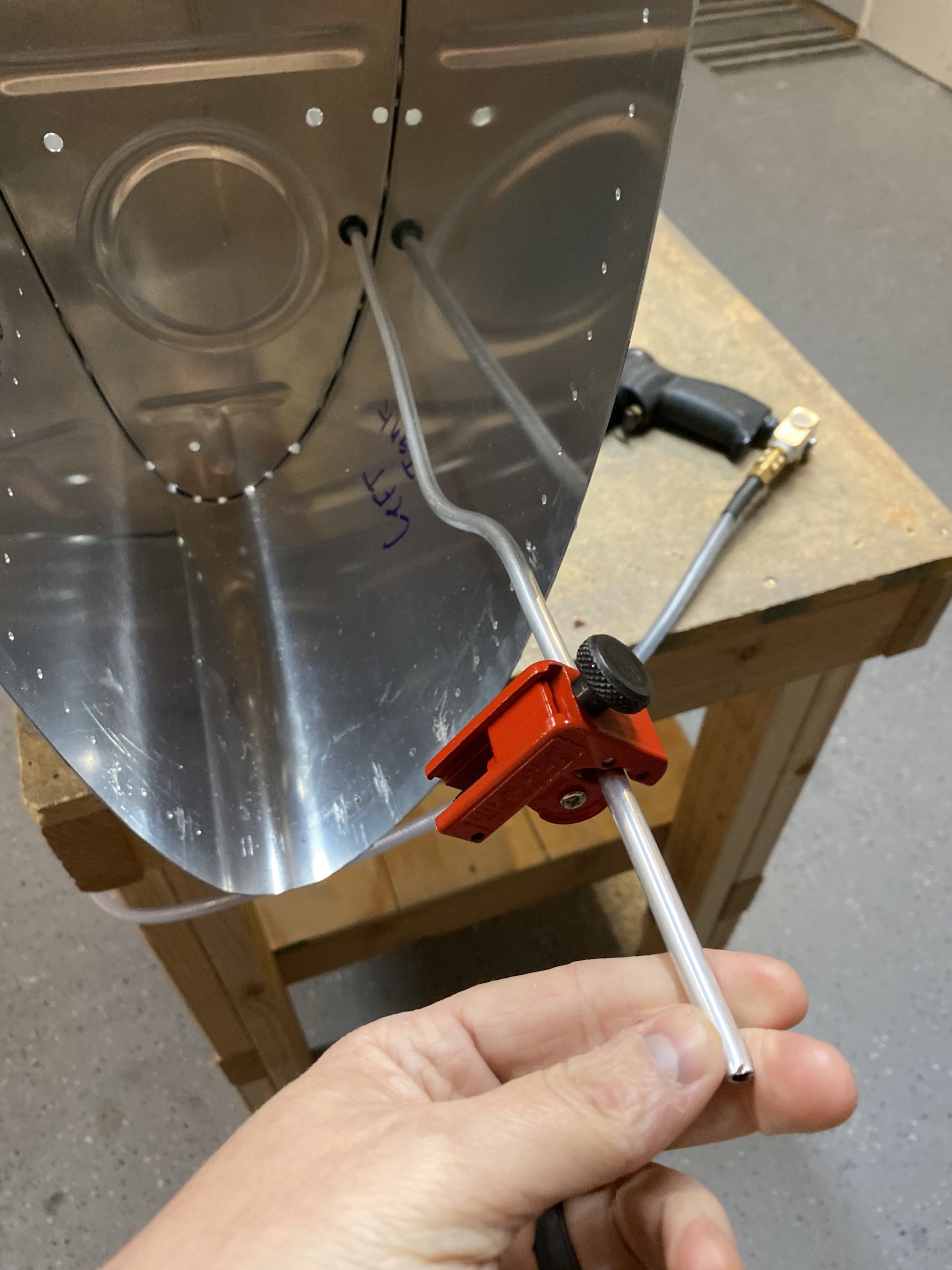
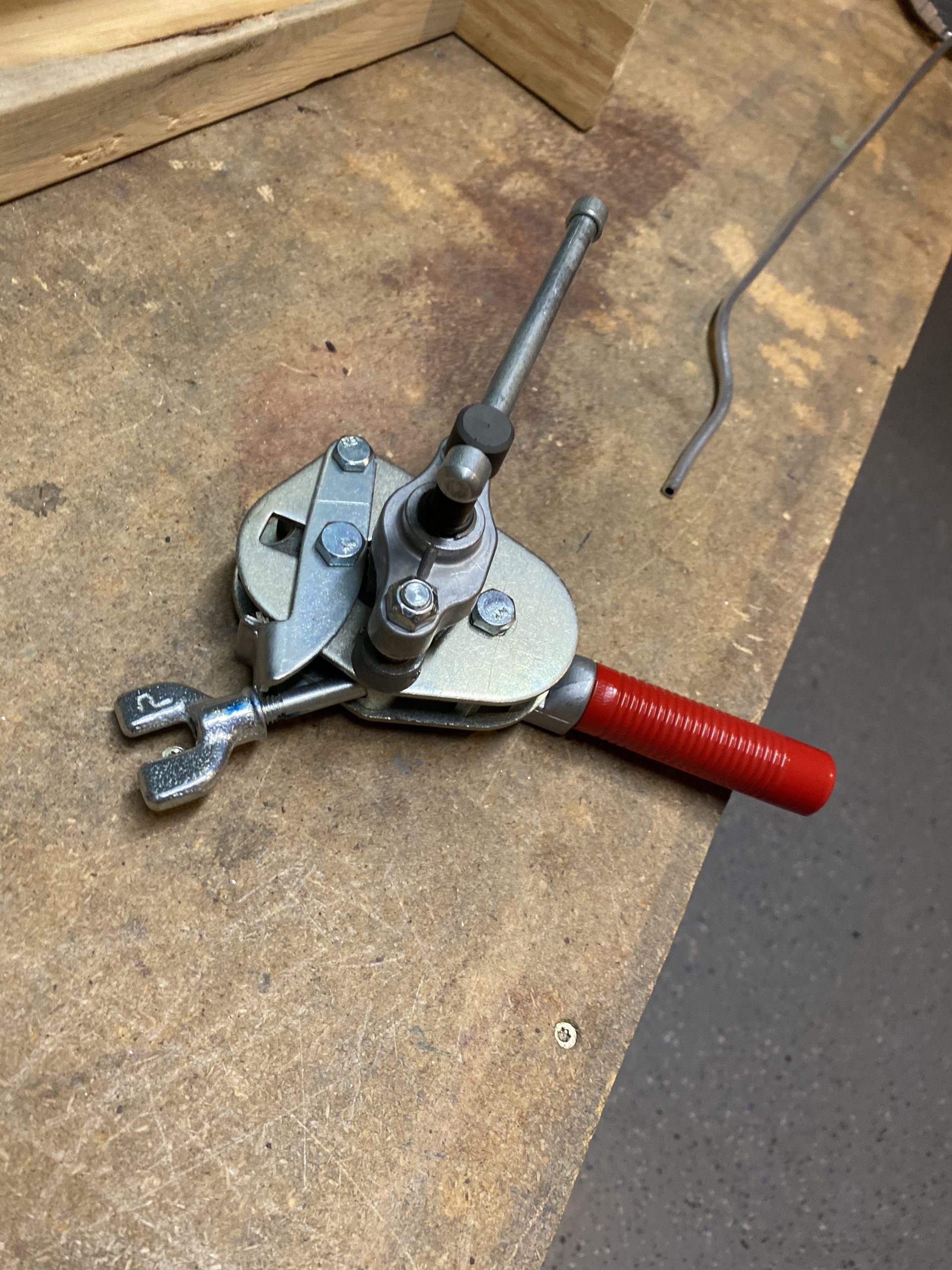
Now its time to bend the float sender wire.  The senders will ship with a float that has plenty of stiff straight wire attached to the float-bobber, and its up to the installer to get the bends set correctly to read full and empty.  So, I clecoed the baffle onto the tank making sure I got the skin nice and flush so I could get an accurate measure on these bends. I installed the sender and clecoed on the baffle!

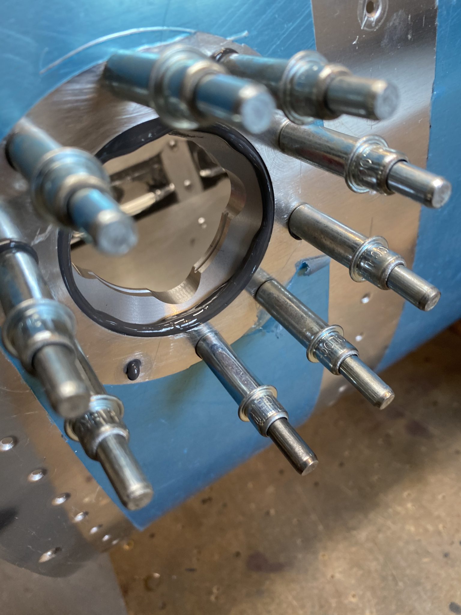
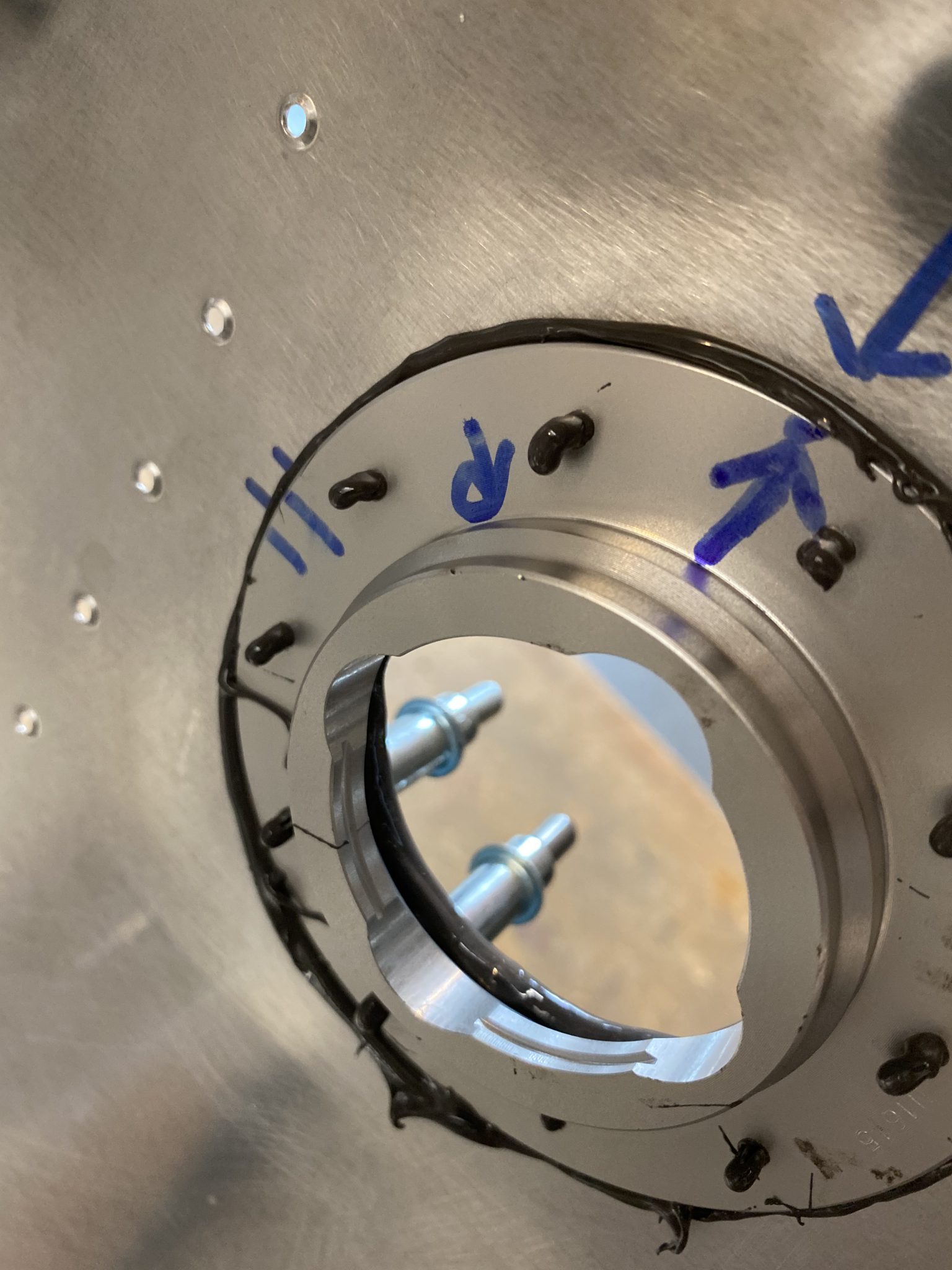
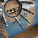
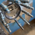
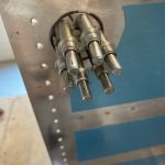
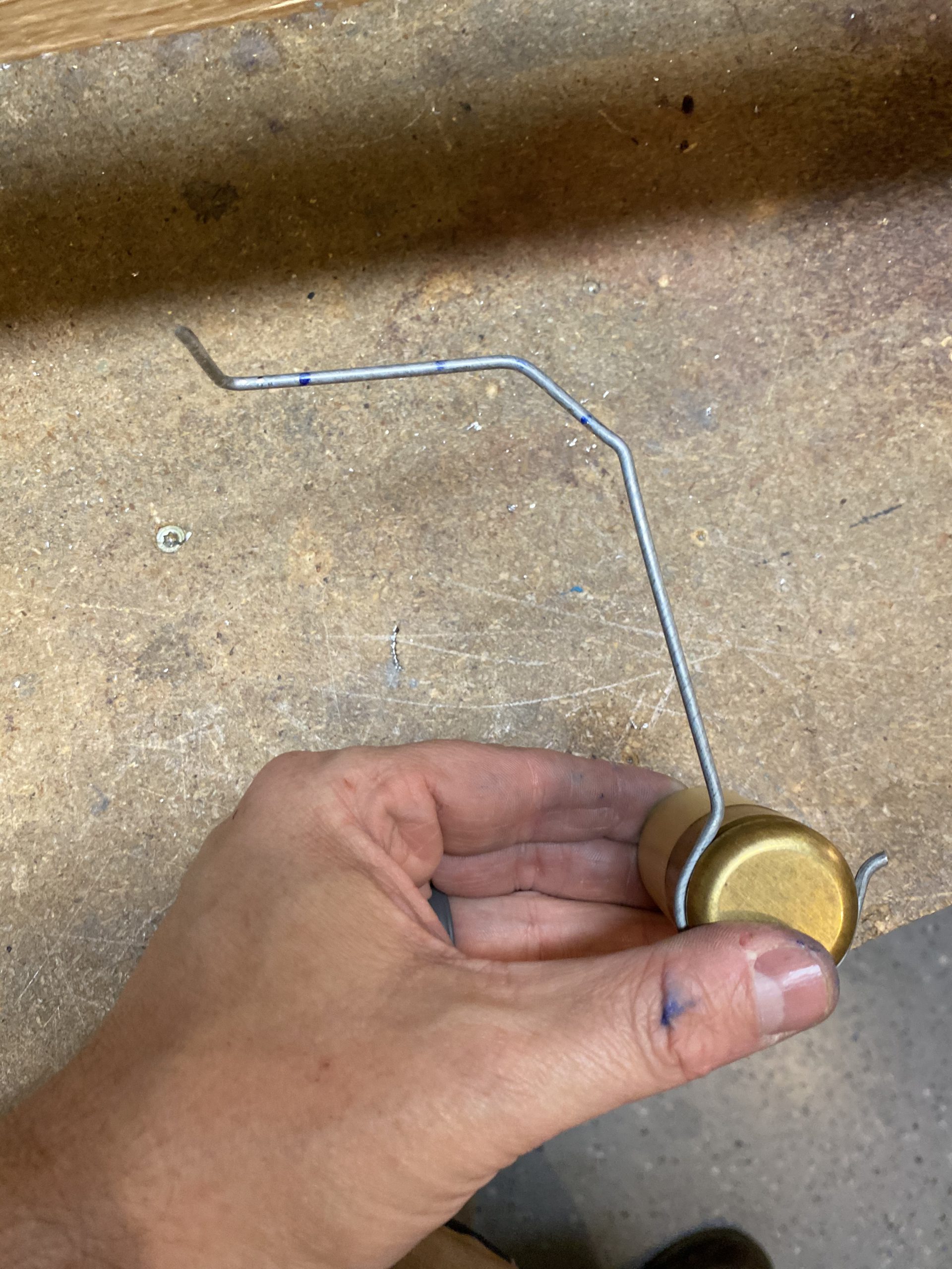
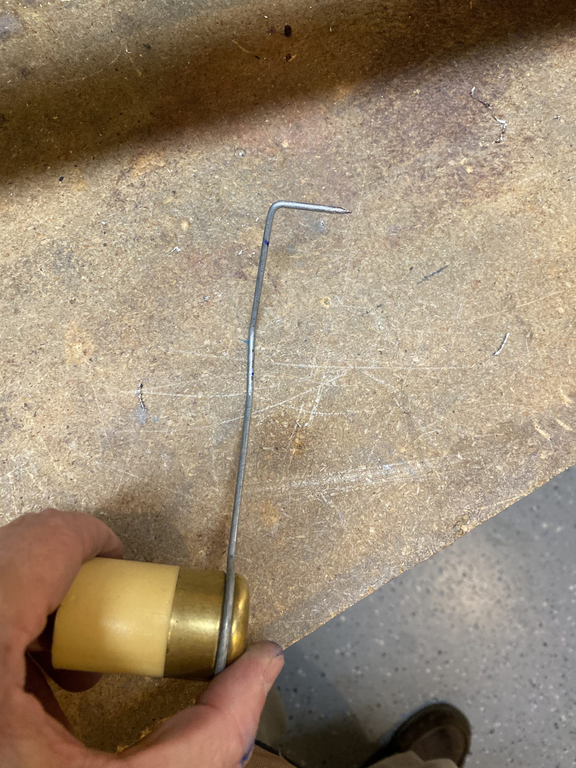
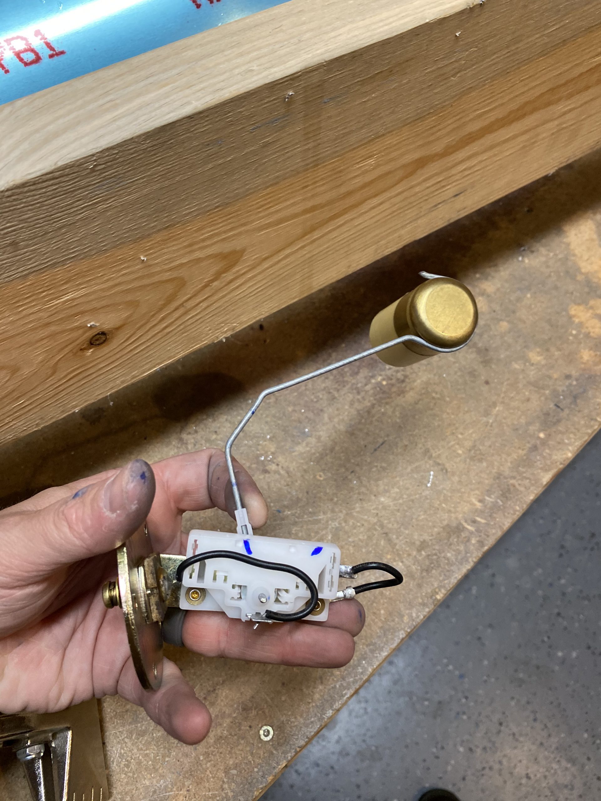
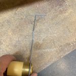
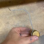
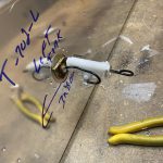
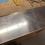
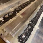
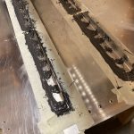
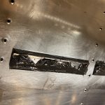
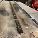
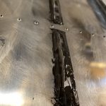
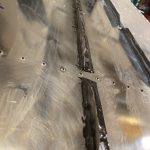
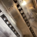
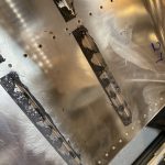
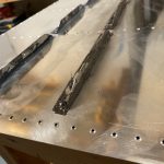
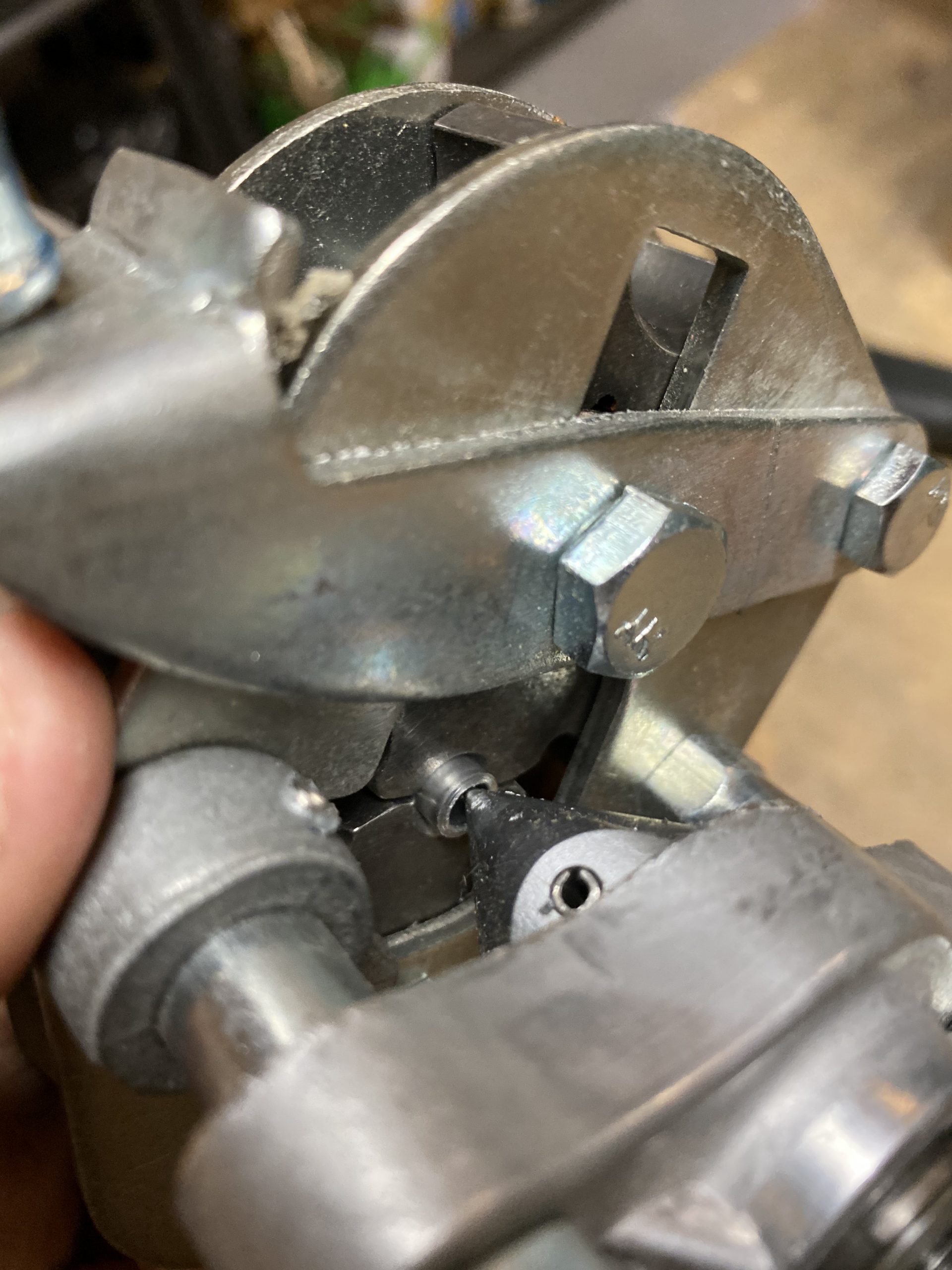
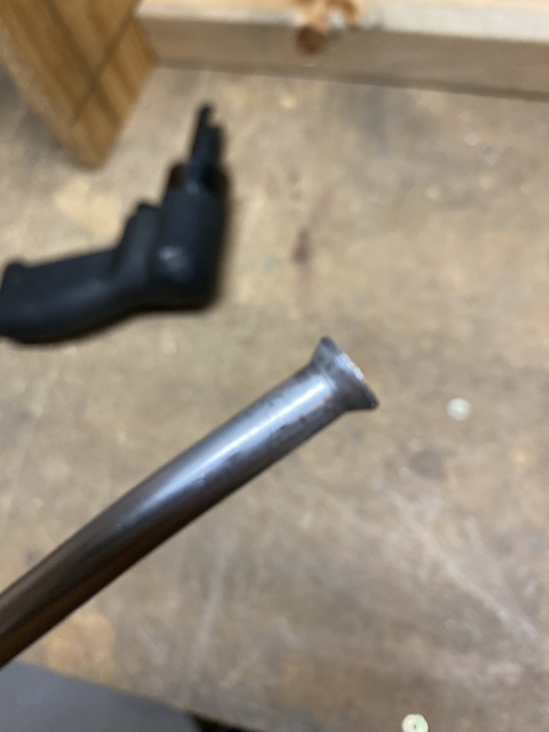
This is where I spent A LOT of time.  It took a lot of trial and error, and testing and bending and fitting to finally come up with a shape that seemed to have worked.  I started off by doing the first bend at 2 3/4″ inches where vans normally recommends 3″.  Then I sort of eyeballed it, and trimmed off the excess, and made a few test bends.  There really wasn’t any sort of “system” or “tips” to make this easy.  Fit the float, and then use a sharpie to mark where you want to bend and see if it works.  Thankfully, the wire on the float is stiff and it seems to be fine being bent multiple times.  The three photos below show what I wound up with.

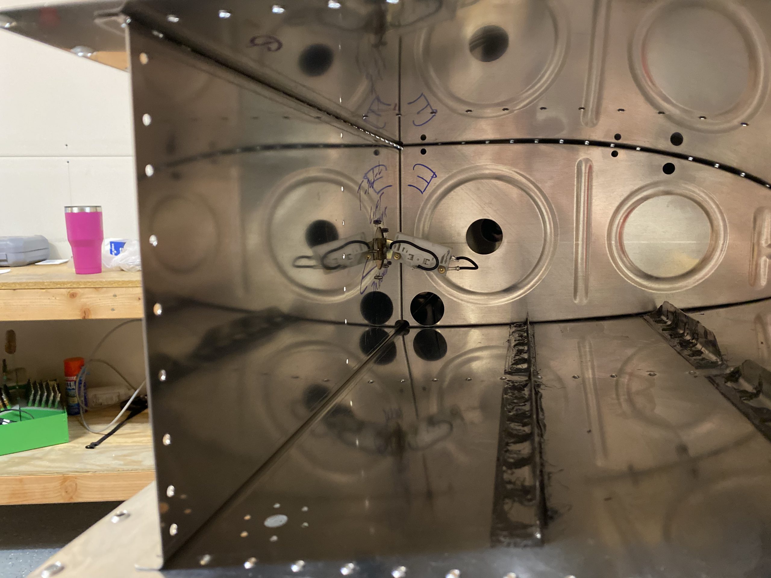
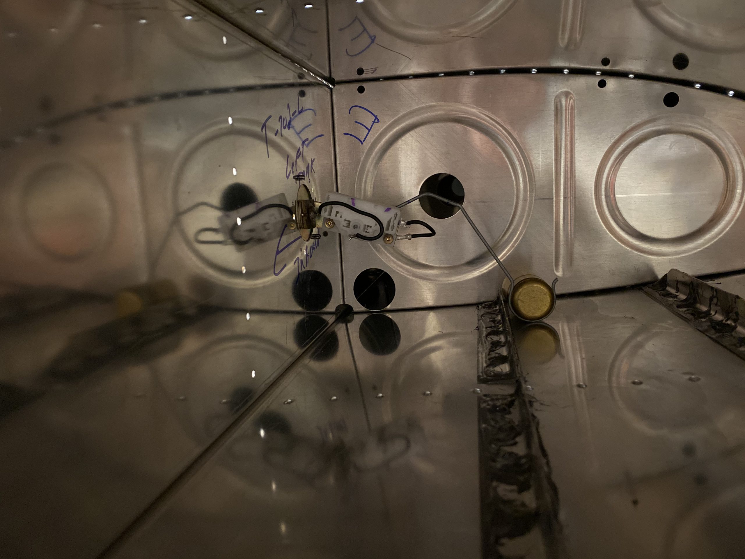
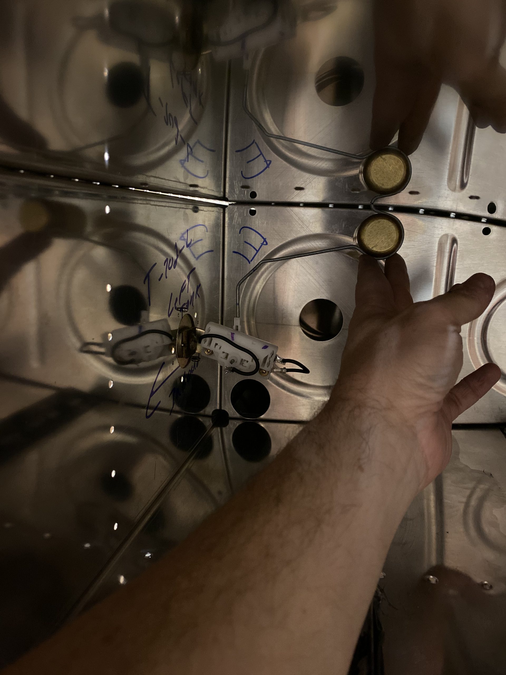
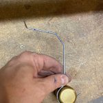
I wanted the float to land just in front of that stiffener, so it would sit JUST above the skin when reading fully empty.  I was able to find a series of bends that did just that, while also giving me a decently correct full position.  The float is maybe 1/8″ of an inch from touching the top skin at the FULL position, which is perfect.  I want these things to read more accurately close to empty than full anyways.  With this sender being outboard by another bay, and sitting a little more forward towards the leading edge, when they read EMPTY, there will probably be close to 3-ish gallons of fuel left in the tank, with about 1/2″ gallon being unusable.  This is a good enough safety margin for me, so when it reads empty, I’ll still have a small reserve.  Here is what I came up with as far as my bends.

    .     

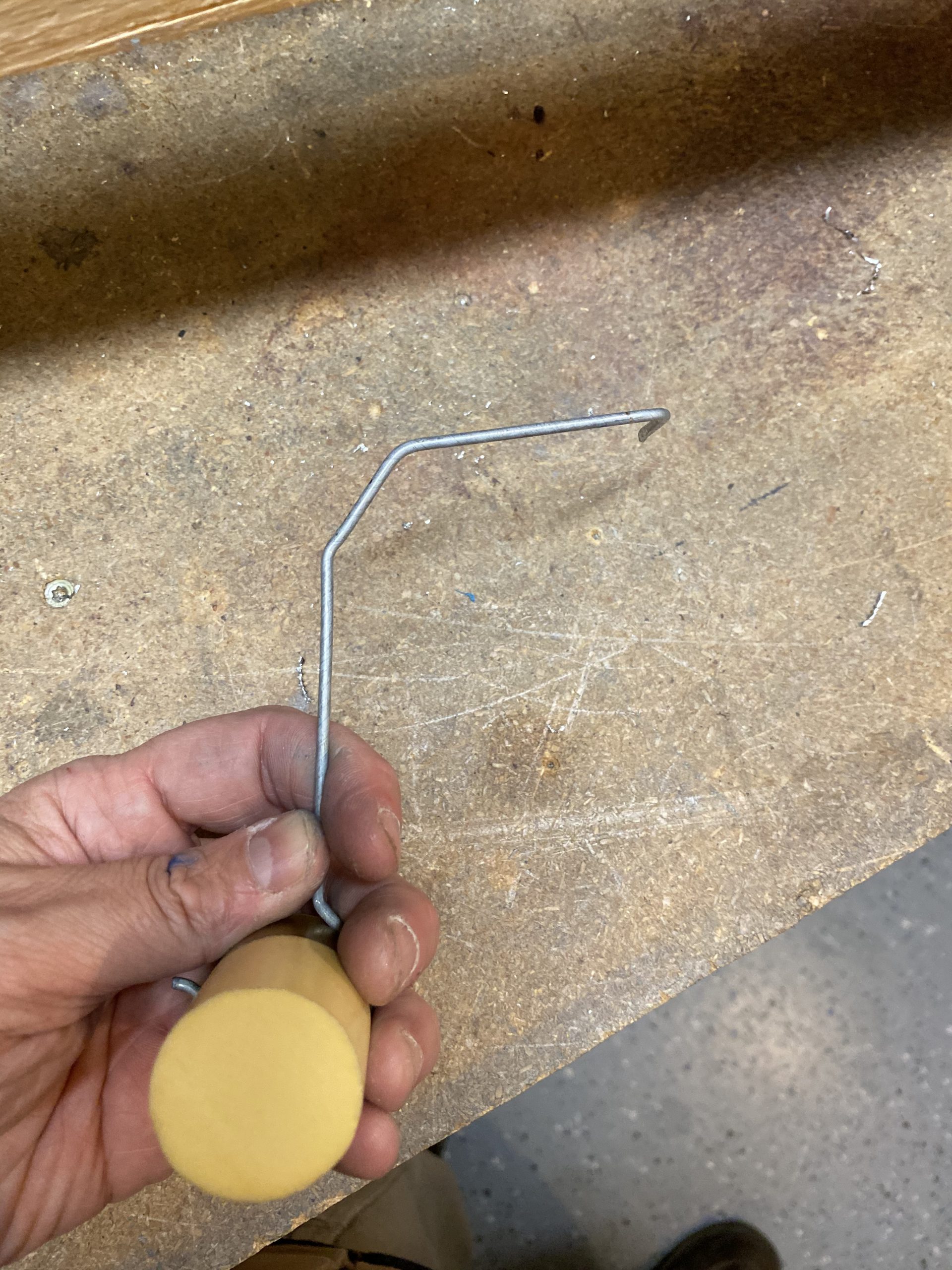
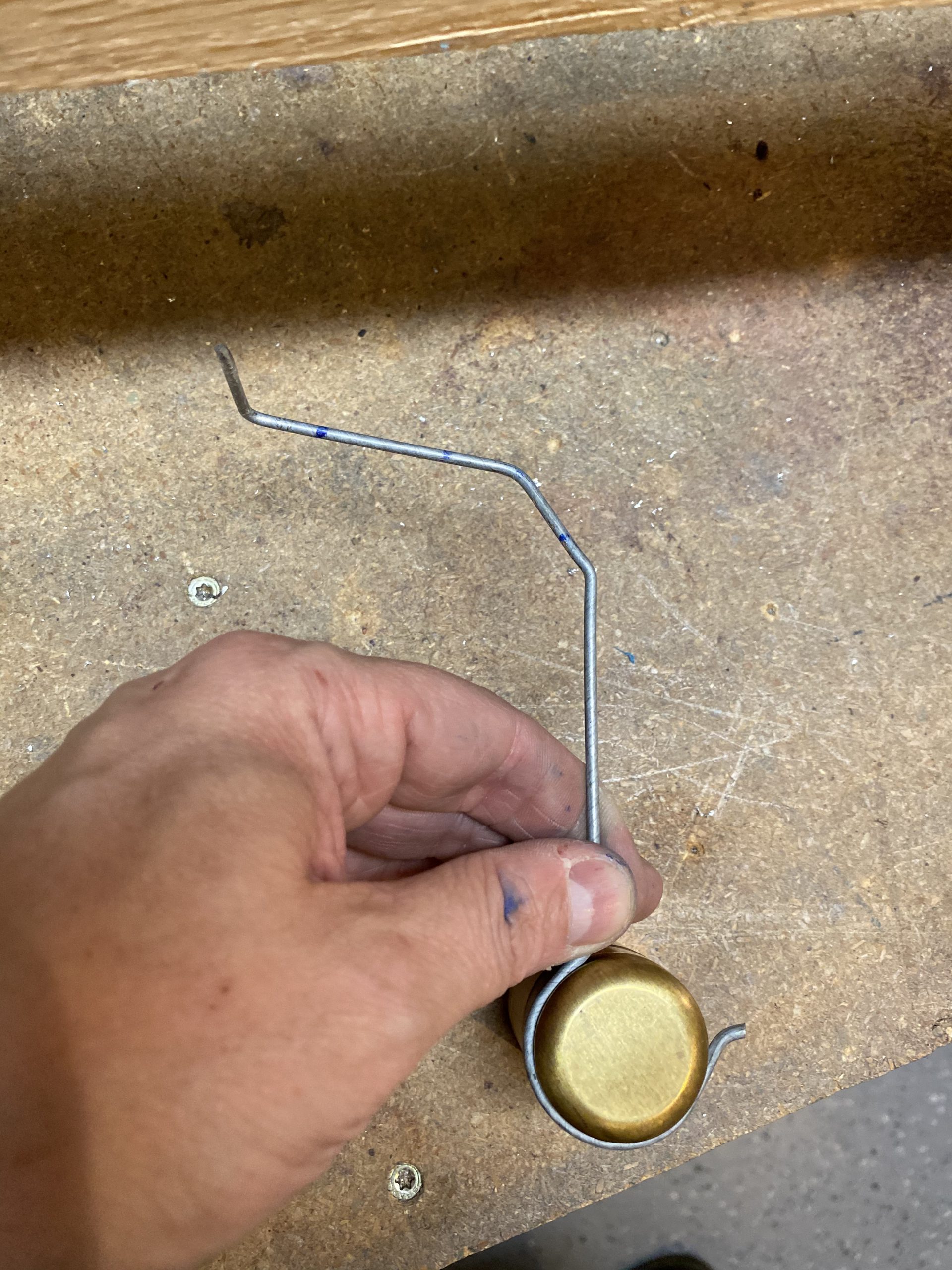
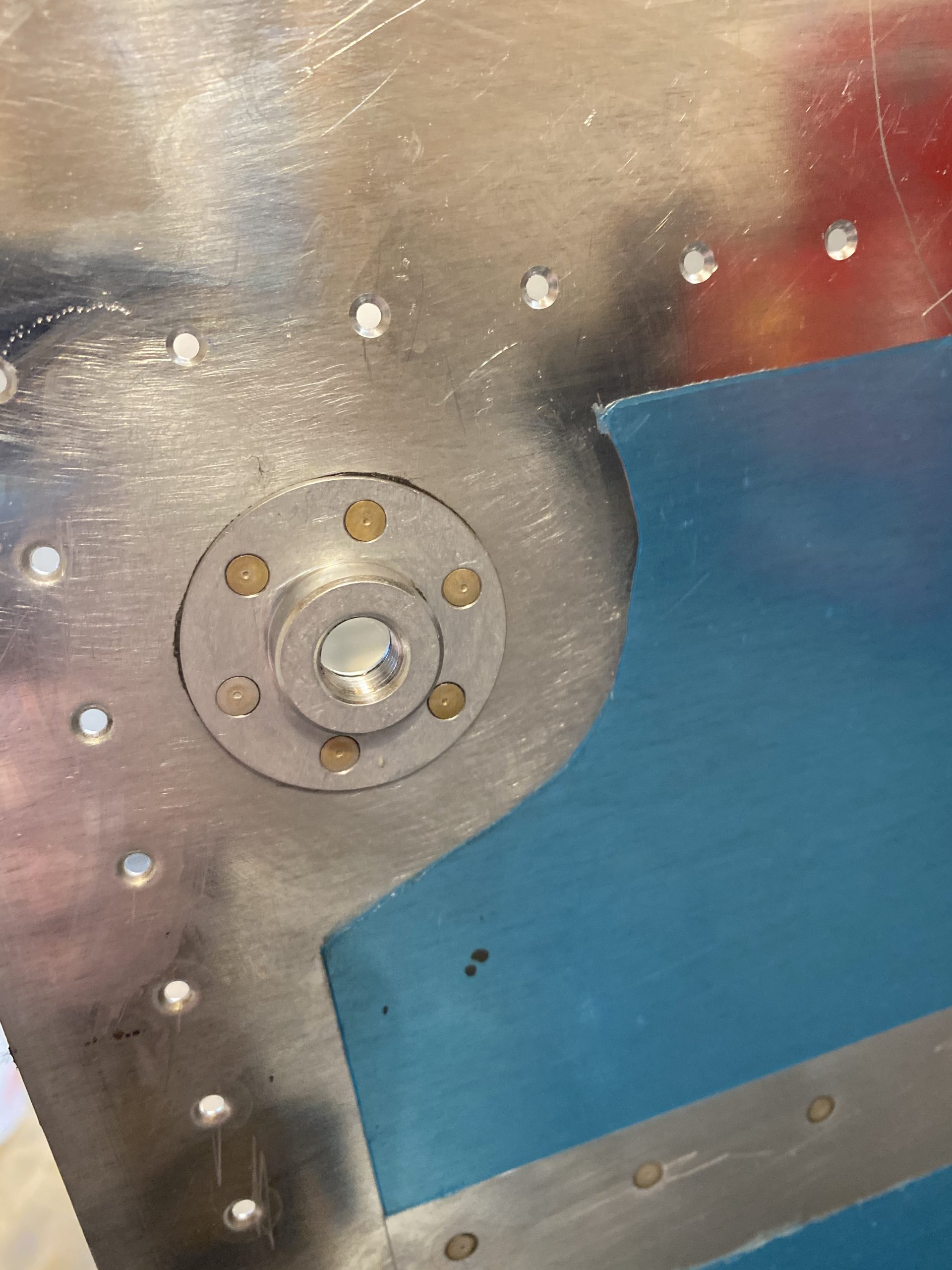
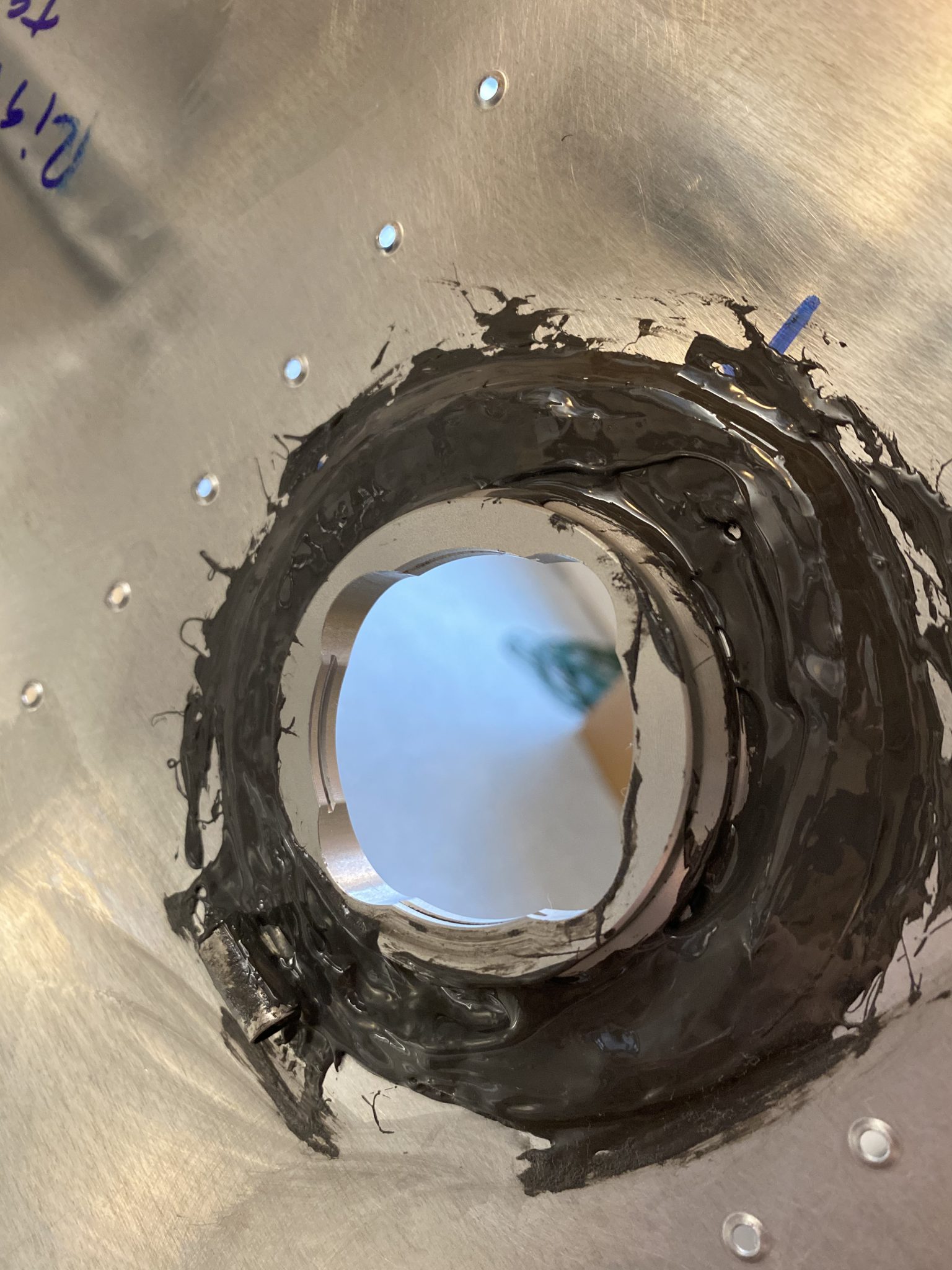
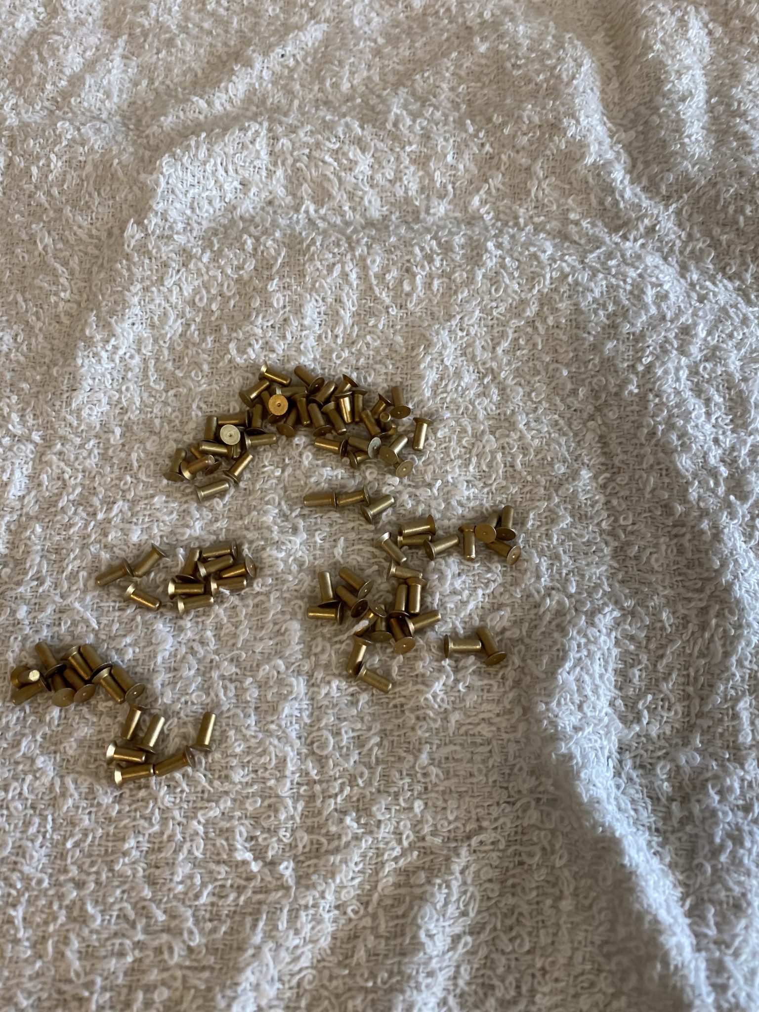
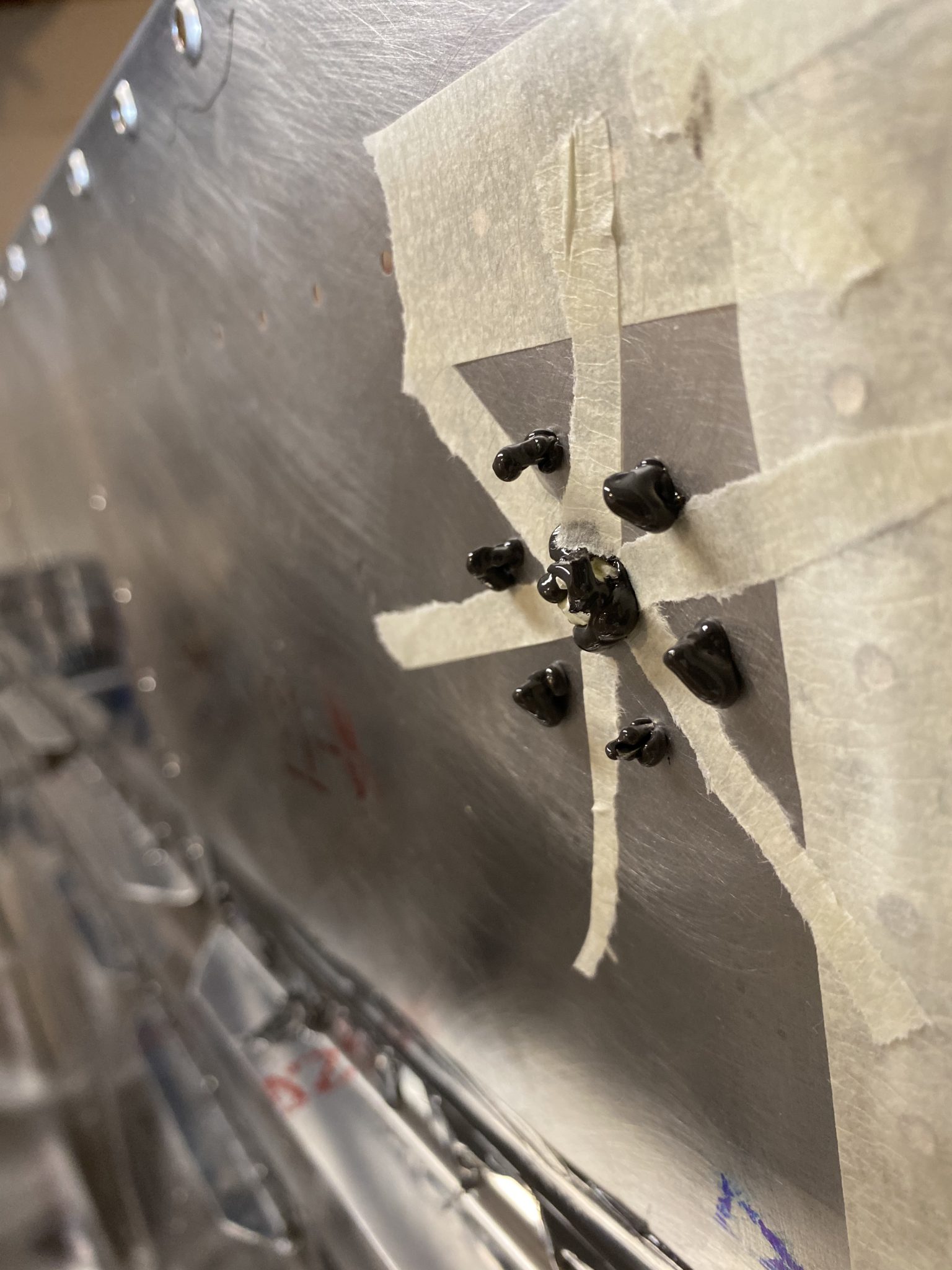
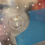
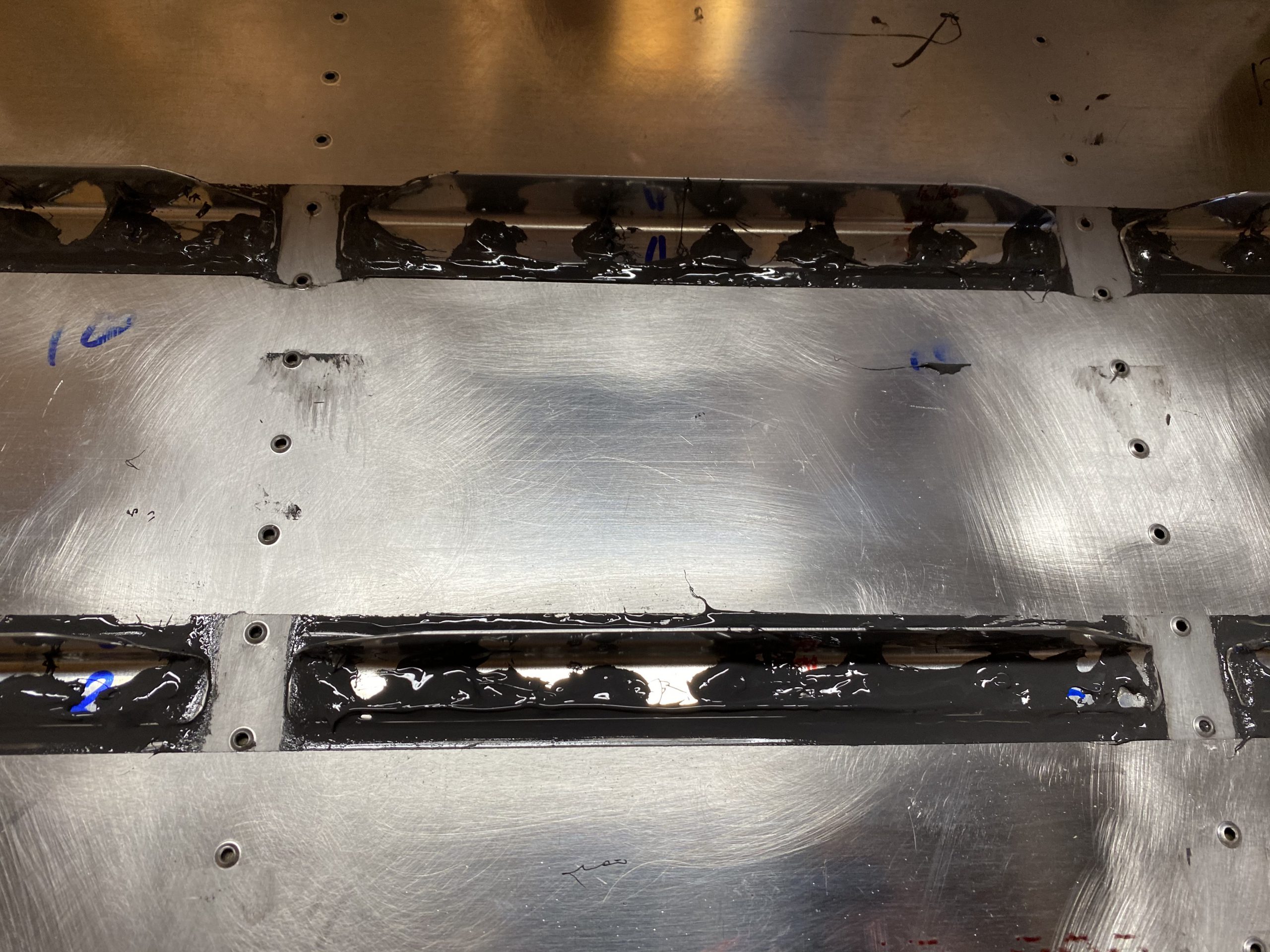
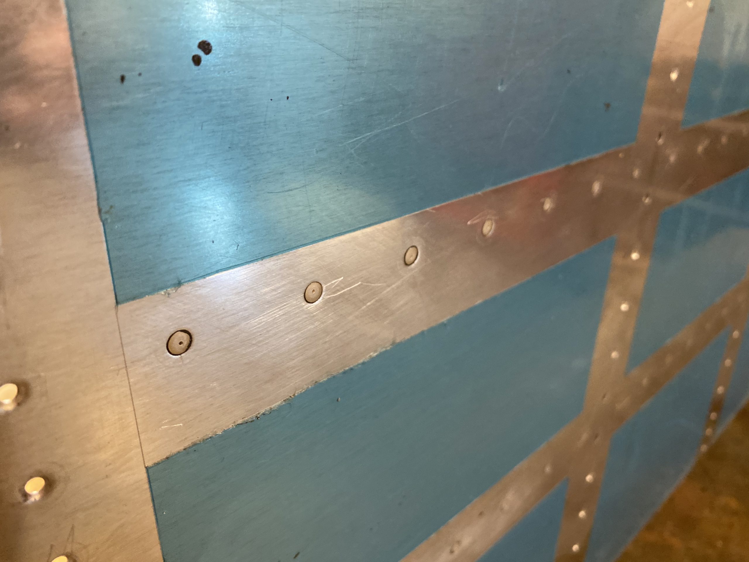
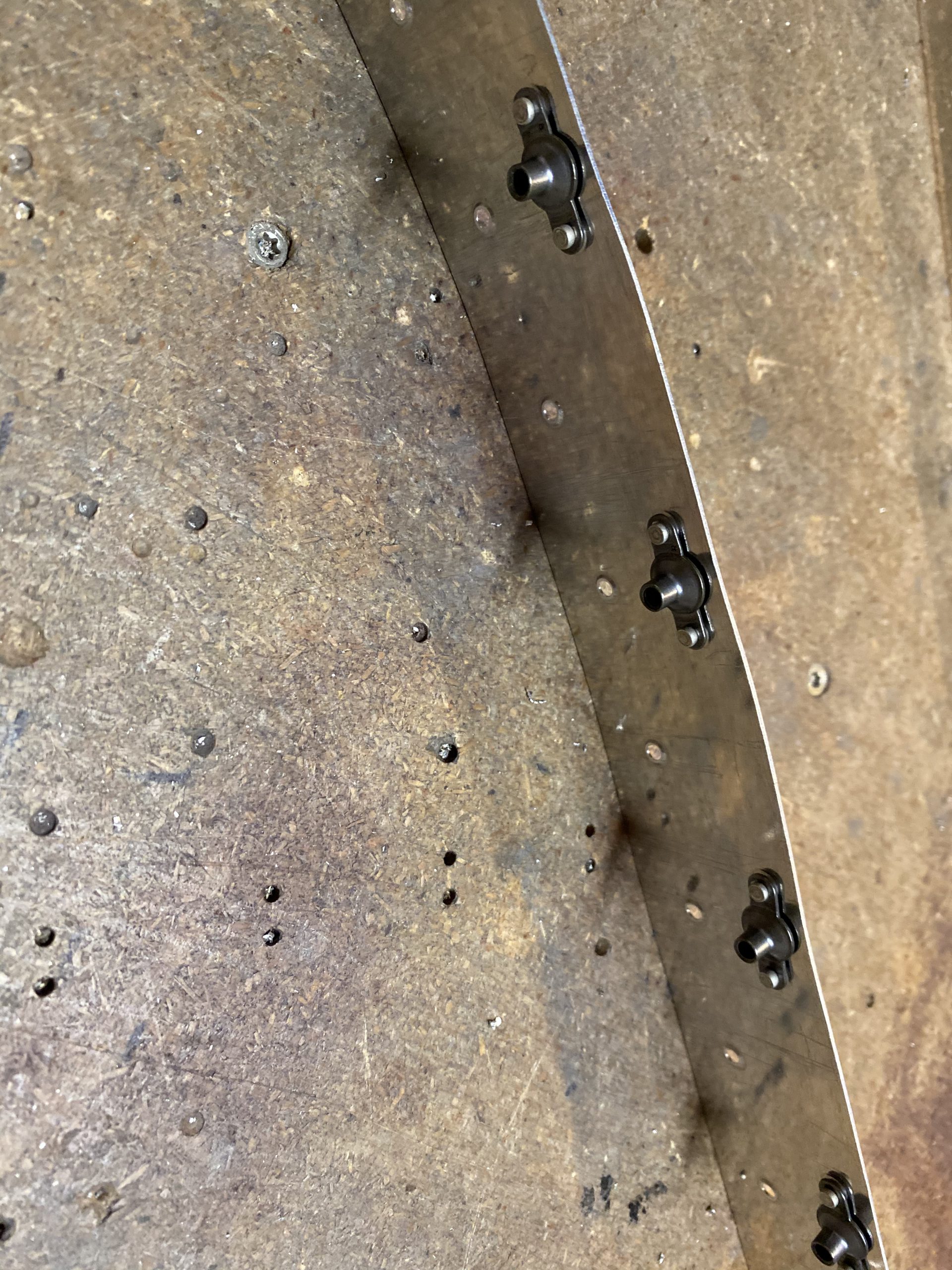
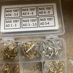
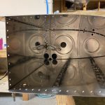
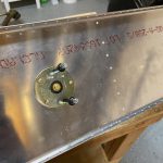
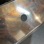
It’s not very helpful without measurements, but honestly, those measurements would vary a bit depending on where you wound up mounting the sender in the baffle anyways.  But, the shape itself is hopefully helpful to any future builders so they can see what worked for me.  Roughly, the float to the first bend is about 2 3/4″.  Then the little distance between the 45 degree bents is about an 1″ to 1.25″.  Then probably another 2.75″ before getting to the 90 degree bend that nests into the sender itself.  With all this hard work of getting the bends done, there wasn’t much left to do, but finish up the mounting holes.  So, I deburred the holes, as well as deburring the larger hole made by the fly-cutter, making sure it was very smooth on all edges.  Lastly, I decided to use some NAS1097 “oops” rivets for an AD426AD3-3.5 hole and do a very easy countersink on the outside rivet holes so that the sender sits perfectly flush and seals good.

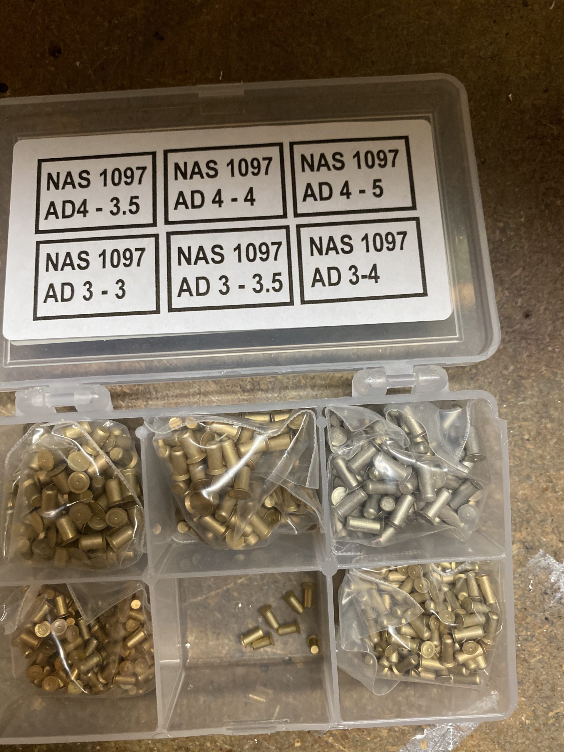
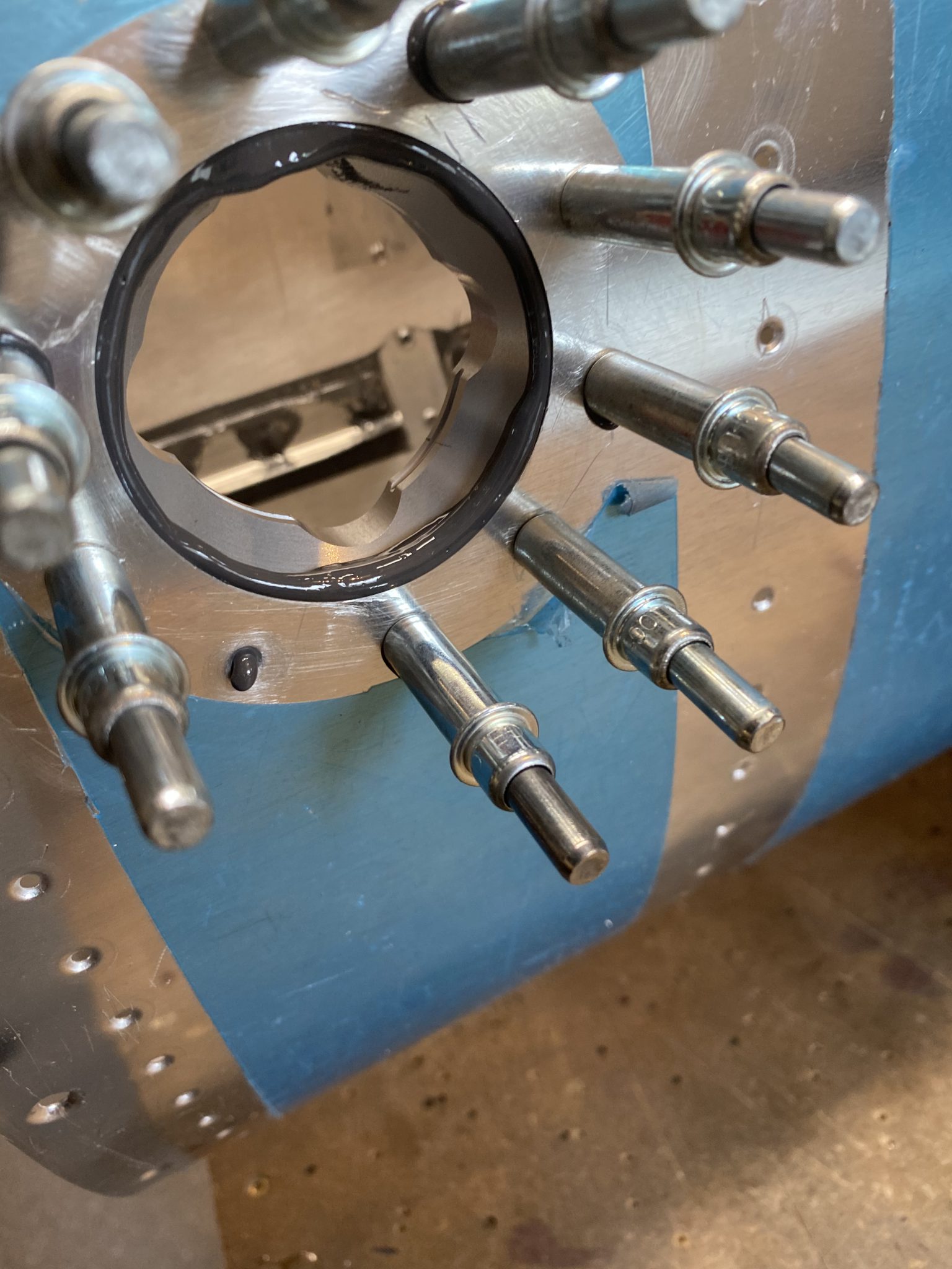
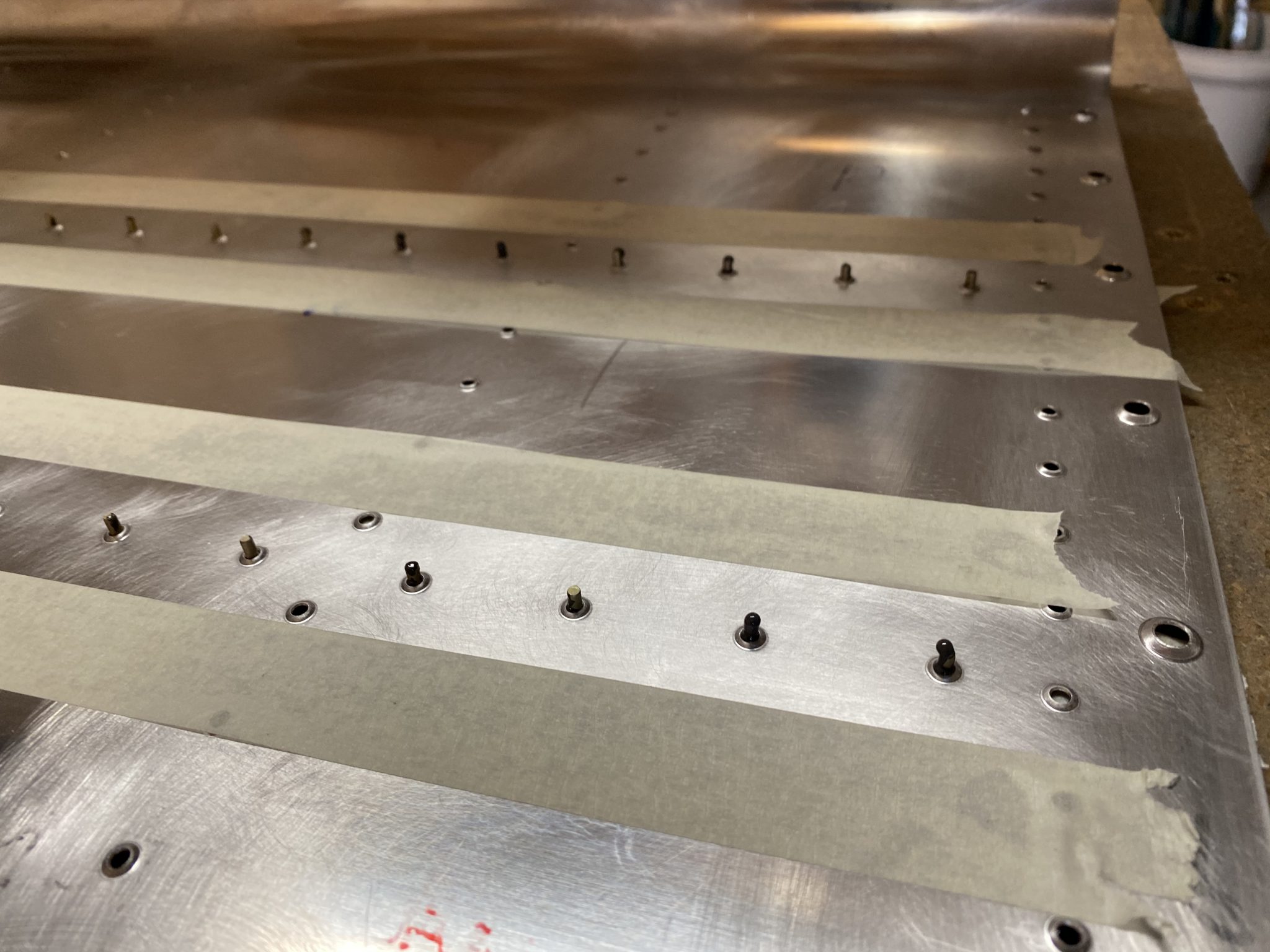
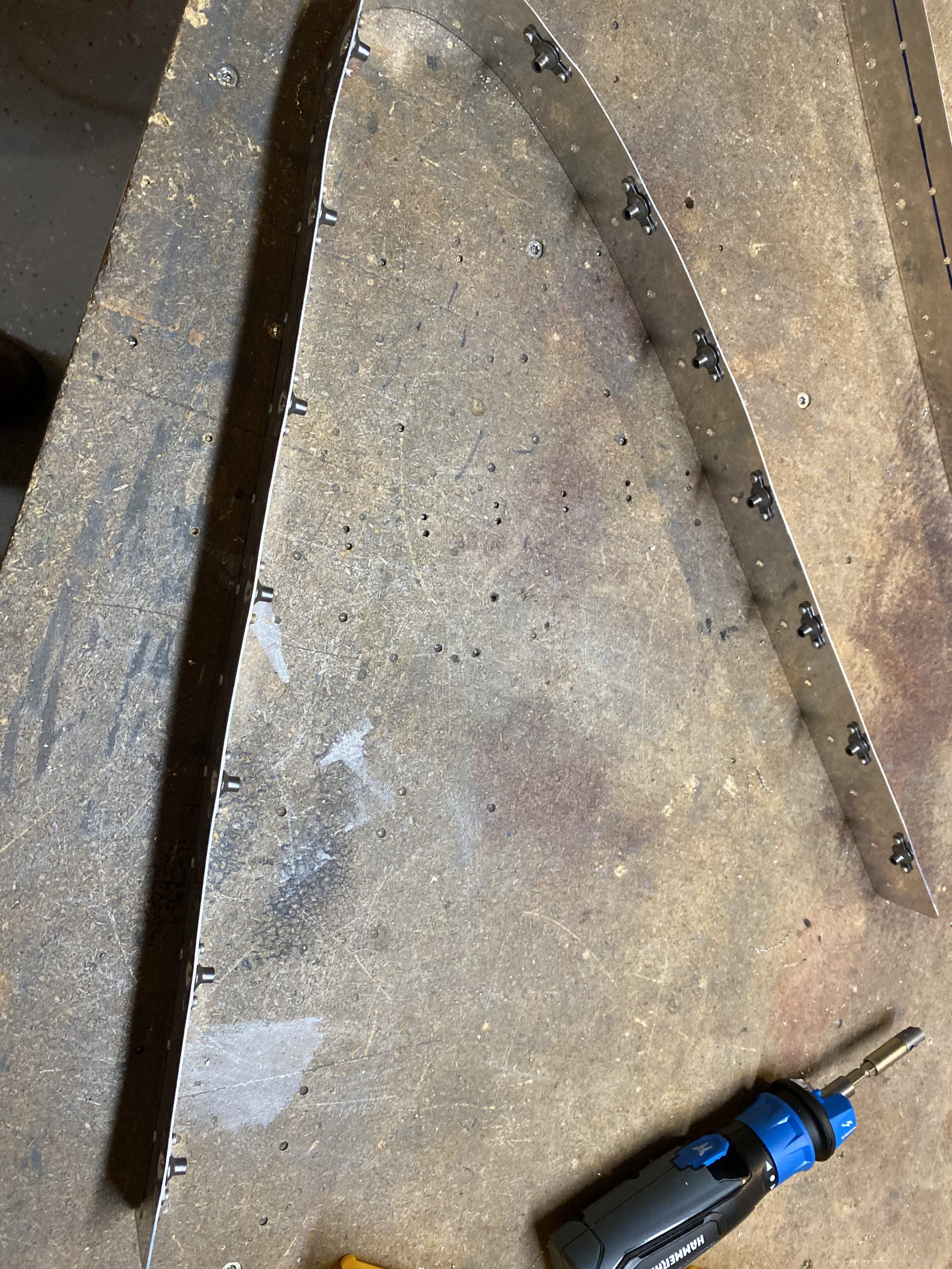
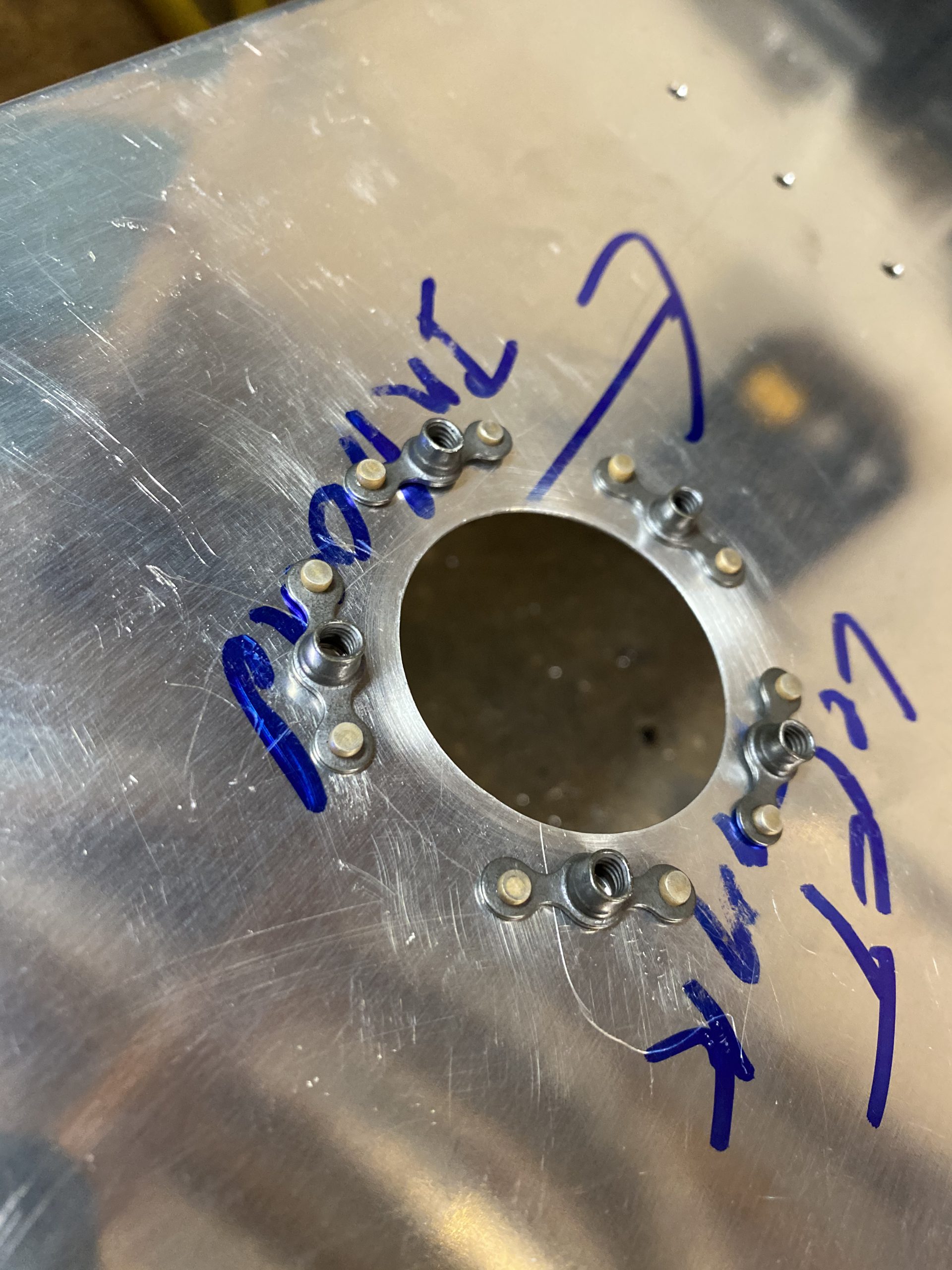
I used my hand deburring tool to get the gentle countersink done just right for these “oops” rivets, since it doesn’t take very much at all.  I tested each hole to make sure it was perfect.  Then I clecoed on the K1000-8 nutplates, and  squeezed the rivets using my squeezer.  I’m pretty happy with the way this turned out!

It feels good to FINALLY get this part done.  I’ve been worried about it for a while, and put a bunch of thought into how I wanted to do it.  I contemplated making a doubler, but decided that wasn’t needed since the sender itself serves as a doubler.  I’m happy with the results! this was a good stopping point for tonight.

Google Photos Link: https://photos.app.goo.gl/j55S1A1HFjNzhipw5

  • IMG_1615
    IMG_1615
  • IMG_1614
    IMG_1614
  • IMG_1613
    IMG_1613
  • IMG_1612
    IMG_1612
  • IMG_1611
    IMG_1611
  • IMG_1610
    IMG_1610
  • IMG_1609
    IMG_1609
  • IMG_1608
    IMG_1608
  • IMG_1607
    IMG_1607
  • IMG_1606
    IMG_1606
  • IMG_1605
    IMG_1605
  • IMG_1604
    IMG_1604
  • IMG_1603
    IMG_1603
  • IMG_1602
    IMG_1602
  • IMG_1601
    IMG_1601
  • IMG_1600
    IMG_1600
  • IMG_1599
    IMG_1599
  • IMG_1598
    IMG_1598
  • IMG_1597
    IMG_1597
  • IMG_1596
    IMG_1596
  • IMG_1595
    IMG_1595
  • IMG_1594
    IMG_1594
  • IMG_1593
    IMG_1593
  • IMG_1592
    IMG_1592
  • IMG_1591
    IMG_1591
  • IMG_1590
    IMG_1590
  • IMG_1589
    IMG_1589

Hours Worked: 3.0


Sealing the Left Tank Stiffeners

Time to work with the black sticky goop again.  This time I decided to do a little more prep work, and forgo pitting sealant on the rivets, instead slather it onto the stiffeners first.  First things, first:  I need to scuff the mating areas, and clean them very well with acetone and MEK.  So, I grabbed a scotchbrite pad and scuffed up the rivet line where the stiffeners would go. It’s a little hard to tell in this photo, but the horizontal row of rivet holes were the ones I scuffed, with about a 1.5″ wide area.

Next step was to clean this scuffed area squeeky clean with some acetone and MEK until the cloth came up clean, and then mask off the areas where I don’t want sealant to go.  I used the stiffeners as my guides, and left a small area around them for the sealant fillet.  Plain old making tape worked fine here.  I also made sure to mask the area off where the ribs would go later on, I didn’t do this on the right tank, and it made a heck of a mess to clean up later.

You can see the difference of where I scuffed in this photo a little better, and the masking shows up a bit better.

This is where things went a little fast, and I didn’t have time to take all my gloves off and snap photos with my phone.  I pulled some AN426AD3-3.5 rivets from my the glass jar where they’d been soaking in MEK, dried them off on a terry cloth towel, and inserted them into the rivet holes.  Then I put masking tape over the rivet heads to serve as back riveting tape, and hold them in place.  Next, I mixed up 50 grams of the white part and 5 grams of the black part of the sealant, and donned all the necessary gloves and protections from the goop, and went to work.  Like I mentioned earlier, I decided to only put the sealant onto the bottom side of the stiffener, THEN place it down onto the rivets and skin.  This was SOOO much easier.  I smeared the entire bottom side of the stiffener with probably 1/8″ or so of sealant, enough so that I would get some squished out when I riveted them onto the skins, but not so much that it’d cause pillowing.  I did ALL my stiffeners like this, placing them into their marked positions on the skins.

Like I mentioned, I REALLY wish I had snapped some more photos, but I tend to get this sealant EVERYWHERE, and I knew it would be all over my phone if I tried to sneak a photo.  But, after I had all my stiffeners slathered in sealant, and placed onto their spot on the skins, I started back riveting them into place.  I slide my back rivet plate into position, and then back riveted the stiffeners starting in their center and working outwards to their edges.  A nice bead of sealant would gently squeeze out from under the stiffener as it went into place, making it really easy to do the fillets later.

Once I had all the stiffeners back riveted into place, I only had enough sealant left in my cup to complete the dollops on the rivet heads on a couple of stiffeners, so I mixed up another 50/5 grams and then applied the dollops of sealant onto the shop heads of all the remaining rivets.  I TRIED my best to not make a huge mess, but as you can see, I was only partly succesful:

But, I’d much rather have too much sealant and be messy than not have enough and deal with leaks.  After I’d dolloped my shop heads, it was time to work the filets around the stiffeners.  The sealant was starting to cure, but that made it a little easier to work with on the filets I think.  I used popcicle sticks to dip some sealant out where needed, and make my filets, making sure to get completely all around the stiffener.

Thank goodness for the masking tape, because I was making a helluva mess.  Once I had all the filets made, I double checked everything looked good, and the removed the masking tape so that the sealant would self level as it cured, and not have any tall ridges where the masking tape was.  The tape came off easy, and left some very clean looking lines!

As you can see above, there were a few spots where I went back and touched up a bit after pulling the masking tape.  I still managed to make a little bit of a mess, but this won’t be hard to clean up once its cured.  Lastly, I decided to check the manufactured heads on the rivets to make sure I had some sealant squeeze around the heads in the dimples from riveting to help seal them.  To my surprise, this process worked very nicely on getting sealant all the way back into the dimple! You can see the dark circles around the rivet in the masking tape in this photo:


And this photo is with the masking tape removed.  You can see where the sealant did a nice job of squishing down into the dimple from the other side! I didn’t wipe this away for now, as I want to cure a bit to make a good seal, it will get sanded away during the painting process anyways.  The rivets were all set perfectly and looked great!

Then it was clean up time.  I only had to clean off my back rivet set in some MEK, as nothing else got contaminated due to the masking job.  It’s well worth the time to mask this stuff off first, and save a ton of clean up time in the end.  I had learned that lesson on the right tank stiffeners 🙂 I’ll leave more photos in the gallery below to show some of the filets and dollops on all the other stiffeners.

Google Photos Link: https://photos.app.goo.gl/QpdfysyHz4afXB2m9

  • IMG_1551
    IMG_1551
  • IMG_1552
    IMG_1552
  • IMG_1553
    IMG_1553
  • IMG_1554
    IMG_1554
  • IMG_1555
    IMG_1555
  • IMG_1556
    IMG_1556
  • IMG_1557
    IMG_1557
  • IMG_1558
    IMG_1558
  • IMG_1559
    IMG_1559
  • IMG_1560
    IMG_1560
  • IMG_1561
    IMG_1561
  • IMG_1562
    IMG_1562
  • IMG_1563
    IMG_1563
  • IMG_1564
    IMG_1564
  • IMG_1565
    IMG_1565
  • IMG_1566
    IMG_1566
  • IMG_1567
    IMG_1567
  • IMG_1550
    IMG_1550


Hours Worked: 2.75


Dimpling the Left Tank Skin

Local weather was pretty crappy, so I didn’t go flying in the Cardinal today, and didn’t have anything else on the docket to finish, so I decided to spend some time working on the RV-7.  Picking up where I left off, I needed to get the left tank skin dimpled so that I can start prosealing it and getting it up the point where the right tank is.  Simple process:  I used my DRDT-2 dimpler, to make quick and easy work of dimpling all these holes.  I made sure to NOT dimple the line of rivets that hold the tank baffle on, as they are machine countersunk instead. I also made sure to dimple the screw holes with a #8 dimple, as this is where the tanks skins screw onto the main spar.

And heres some photos of me doing the work, so I can prove to the FSDO that I am the guy building this thing.  I am hoping to get the repairman certificate for this aircraft, if and when it ever gets done! I was working by myself, so I hope a couple of selfies is OK.


I did complete the tank skin in a little over an hour.  I spent probably ten minutes catching up and reading where I left off, nearly a month ago! I have got to start making these a bit more frequent, or she’ll never get finished.

Hours Worked: 1.25

Stall Warner Continued

After finishing up a previous build session on the fuel tanks, I decided to change gears a bit, since I got some new tools/toys!  I FINALLY bought a proper set of crimpers ands strippers from SteinAir! I was needing these to finish up some wiring on the stall warner.  So, picking up from this previous post  I opened my fresh tools and put them to work.  SteinAir has a really good video on how to use these crimpers, so I gave it a watch, and went to work.  I needed to cut a 3.5″ piece of 18 gauge wire and crimp two ends on it to serve as the ground point for the stall warner.  Easy enough with the new tools.  Heres the before and after:


These crimpers are well worth their money! They make a very nice, professional looking crimp, that has excellent strain relief and makes super tight connections.  I highly recommend them if you are looking for a good set!  I had already assembled the stall warner in a previous session, so its pretty much ready to bolt in, now that I have this electrical connection made up.  Next up was to rivet on the nut plates for the access plate doubler.  I’d already dimpled them a long time ago, now it was time to fix them onto the doubler.

I clecoed on the nut plates lining up the holes, then I inserted an AD426AD3-3.5 rivet and squeezed it with my squeezer.  After I had all the initial holes squeezed, I pulled the clecos out, and then squeezed the other holes in the nut plates.  I had already dimpled all the holes in the doubler, so now it’s completely ready to go into the leading edge.

I ALMOST decided to go ahead and install the entire stall warner assembly, the doubler and access plate onto the leading edge, but I decided to shelve the parts for now, since I am planning on shooting the leading edge skins in primer before final assembly.  I plan on passing this thing down to my daughter when I get too old to fly it, so priming will only help to preserve it.  So, the doubler, access plate, stall warner, and stall warner mounting plates and all the hardware for these pieces went back into their bag, and on the shelf for a little while.  I’ll get the tanks almost done (with only the baffles remaining), so they can cure, then I’ll start priming the leading edge and wing skins for final assembly.


Hours worked: 0.5

Deburring and Dimpling the Left Tank

FINALLY got some time to get a little work done on the RV-7 again.  Lots of projects going on and been focusing on family time over building.  It was good to get back and do some work with my hands though.  Not much to report.  I was able to get all of tank skin holes deburred, and the tank skin edges deburred.  I also dimpled the ribs and stiffeners using a combination of my DRDT-2 and squeezer.  Then I finished off the night by deburring the edges of the tank baffle.  I’ll tacked dimpling the tank skin in the next build session, and then its time for Pro-seal.

I also went ahead and trimmed the plastic sheeting off the rivet lines using my dull soldering iron.  Thats it for tonights session.  Just something to get me back in the swing of things.  With the summer months, its hard to get down in the basement and work since we have soooooo much awesome daylight.

Hours Worked: 1.5

Deburring Left Tank Parts

No Proseal work tonight, but its close.  I need to get the left tank up to the same point as the right, which means breaking it down, deburring, finishing the edges, and then dimpling.  First I need to trim my vent tube, and flare it for its fitting. I measured and marked the tube where it goes into the bulkhead fitting, and then trimmed it using a tubing cutter.

I used a Parker flare tool to make the flares perfect.  This tool makes it really easy to get a nice and perfect flare every time and its simple to use.

.        

Finally put on the fittings and done them up finger tight so that I could measure and trim the very far end near the outboard of the fuel tank, where the fuel cap is.  I left a good bit extra on this tubing, so I needed to trim a decent amount on the end.

Once that was done, all that was left was to disassemble the tank and get the parts ready for deburring.  I started deburring all the small parts first, and I made pretty decent progress before I decided to call it a night.  Since I used a reamer on most of these holes, the deburring process went really quickly, and with much less effort.  These are all the parts I was able to get deburred tonight:

All that I have left to deburr is the holes on the ribs.  Then I’ll follow all the pieces up with some edge deburring to get everything ready for dimpling.  I still need to deburr the skin though.

Thats it for tonight.  Decent progress on these parts.  I’d say I have another hour or two of deburring and edge finishing before I’m ready to dimple these parts.  Then its scuffing for sealant, and then sealing.  Lots of work going into these tanks!

Google Photos Link: https://photos.app.goo.gl/hFeupKe9wpfhHRMD8

Hours Worked: 2.0

Sealing the Right Tank Drain and Fuel Cap

Another proseal session tonight, but this was a pretty short one.  This stuff is still messy, and I still have a hard time dealing with it, because I am not good with messy stuff!  I wanted to get the tank drain, and the fuel filler sealed and ready to go, since the next steps after this will be installing the ribs.  I started off by scuffing up the areas I wanted to seal, and then cleaning those surfaces REALLY good with acetone and MEK.  After that, I used some masking tape to prevent me making a mess in places I didn’t want sealant.   More specifically, I wanted to mask off the interior part of the tank around the tank drain to leave little draining channels clear so that water can get to the tank drain with no obstruction.  Here is how I did that:

Then I suited up with some gloves, and mixed up about 2 ounces of proseal.  I decided to get the tank drain done first since it was small and easy to get to.  So, I applied a decent layer of proseal onto the tank drain fitting itself, and then cleco’d it onto the skin.  This made things less messy, with only a little squeezing out the sides.

.  

After I got the tank drain clecod on with its sealant I decided to do the same for the fuel filler, and then move on to riveting.  This way I had at least got the sealant applied and clamped down to both parts.  So, I did the same, applied the sealant to the top of the fuel filler flange (the part that mates with the skin), and clecoed it on.  Granted, these parts were also scuffed and cleaned earlier in this sesison.

I sloshed some rivets around in a jar of MEK to get them nice and clean and then dried them on a clean towel, and squeezed them all into the tank drain first..  I was able to use my squeezer on all of the rivets on the tank drain pretty easily.

This was a messy job, as proseal was getting all over my squeezer and clecos.  But thankfully, it cleans up really easily with MEK. Here is the exterior of the tank drain, after I riveted it, and cleaned up all the proseal.

Next up, I put a dollop of proseal on the backside of each rivet on the inside of the tank to help them seal.  Once I was happy with the dollops, I removed the masking tape, and cleaned up the area to provide the water drainage channels for the tank drain.  I used some q-tips soaked with MEK to make this process easier.  I also made sure to fully clean all the goop out of the threads of the drain.


This isn’t the most neatest of jobs, but its very functional.  I am just hoping I am getting these things sealed good! Next up I moved on to riveting the fuel filler flange.  This was TOTALLY messy, and I did not get any photos of me during the process because my hands were essentially covered in proseal.  I was able to squeeze maybe 6 out of all these rivets, I had to use a bucking bar and rivet gun on the last few because my squeezer wouldn’t reach them.  Then, after I had the rivets set, I smeared a good coat of proseal over the entire inner surface of the filler flange.  This was probably overkill, but I figured why not?  Might as well be sure that this thing is gonna be sealed up nice and tight.  This is how it looked all messy, before I cleaned it up with some MEK and paper towels

And here is the outside view AFTER I cleaned up all the excess proseal.  You can see the faint black line on the inner side of the filler flange that is helping keep this sealed.  The rivets look nice and flush and what you are seeing is the scuff marks from where I scuffed the dimples.  These will get buffed out when its finished for painting.

That wraps up this proseal session.  I had some excess left, so I would say 1 or 1.5 ounces would be plenty to do the filler flange and tank drain.  I’ll keep this in mind when I do the left tank.  I left the tank in the tank stand / jig to help it hold shape while the filler flange dries, since its formed around the leading edge curve a bit.  I’ll leave this as is for a few days to cure and dry, I still need to prep the left tank and get it ready for sealing.

  • IMG_1117
    IMG_1117
  • IMG_1116
    IMG_1116
  • IMG_1115
    IMG_1115
  • IMG_1114
    IMG_1114
  • IMG_1113
    IMG_1113
  • IMG_1112
    IMG_1112
  • IMG_1111
    IMG_1111
  • IMG_1110
    IMG_1110
  • IMG_1109
    IMG_1109
  • IMG_1108
    IMG_1108
  • IMG_1107
    IMG_1107
  • IMG_1106
    IMG_1106
  • IMG_1105
    IMG_1105
  • IMG_1104
    IMG_1104
  • IMG_1103
    IMG_1103
  • IMG_1102
    IMG_1102
  • IMG_1101
    IMG_1101
  • IMG_1100
    IMG_1100

Google Photos Link: https://photos.app.goo.gl/PeBtsgKAZdjoCTBM7

Hours Worked: 1.75

Sealing and Riveting Right Tank Stiffeners

Its time.  Time to start working with this sticky, smelly, nasty sealant again.  I have not really been looking forward to this, but it has to be done.  My right tank has been scuffed and semi-cleaned in the last couple of build sessions, so I wanted to give it another quick scuff and clean it really well with MEK to get a good bond with proseal.  After I had the skin all cleaned and scuffed, I did the same to the stiffeners.  I pulled a big scoop of AN426AD3-3.5 rivets and put them in a glass jar with some MEL to soak off any manufacturing residue.  I’d give them a shake every now and again to agitate them around.

Next up was to mask off the area to help make clean up easier.  Plan old masking tape worked good for this, and I left enough room for the filet around the stiffeners.

I mixed up a batch of proseal, using the 10-1 ratio.  I mixed 120 grams of one part and 12 of the other, and then made sure it was all nicely mixed together.  I dabbed. little bit of sealant into each dimple to help seal the tanks, which made a big mess, especially trying to put rivets in there.

Eventually I managed to get a rivet into each hole, making a hell of a sticky mess.  I double gloved so I could switch out my gloves easily.  Once I had a rivet in each hole, I slapped on some masking tape to act as back rivet tape.

Now it was time to smear on the sealant on the inside of the skins.  I used a cheap paint brush, about 1/2″ wide, and I cut the bristles down very short to make spreading this thick goo easier.  I did not get any pics of this, because I was an utter mess, gloves covered in this stuff, and I didn’t want to get it on my phone. Once i had a good covering of sealant where the stiffeners go, I placed them over the rivets and pressed them into place.  I pulled out my back rivet plate, positioned it under the stiffener and used a back rivet set on my rivet gun to set the rivets.  I had to work a little fast here because my sealant was starting to harden, and I am inexperienced so I didn’t get many pics.

After I had all the rivets set, I came back over with some popcicle sticks and formed my filets around the stiffener edges, and used the extra sealant I scooped up in this process for the little dabs that covered the rivet tails. This was super messy.  I think I used a little too much sealant! hah.

The pic above is after I pulled the masking tape off, during clean up.  Like I mentioned, my gloves were covered in this stuff, I didn’t want to chance getting it on my phone.  But, even though this was my first time, and I spent more time on it that most people, I think it came out OK.  I am just hoping its sealed up nice and tight, and I wont know until I do some pressure testing.  I pulled the rivet tape of the outside of the skin, and cleaned up the excess sealant with some MEK.  MEK really does a good job of cleaning this stuff up.

You can just barely see a small little black area around the rivet head where the sealant squished around it.  The excess cleaned up nicely.  I’ll put lots of photos in the gallery below of how they came out.  Fingers cross they wont leak! I’ll let this harden a bit while I work on deburring and dimpling the left tank and getting it ready.

  • IMG_1083
    IMG_1083
  • IMG_1082
    IMG_1082
  • IMG_1081
    IMG_1081
  • IMG_1080
    IMG_1080
  • IMG_1079
    IMG_1079
  • IMG_1078
    IMG_1078
  • IMG_1077
    IMG_1077
  • IMG_1076
    IMG_1076
  • IMG_1075
    IMG_1075
  • IMG_1074
    IMG_1074
  • IMG_1073
    IMG_1073
  • IMG_1072
    IMG_1072
  • IMG_1071
    IMG_1071
  • IMG_1070
    IMG_1070
  • IMG_1069
    IMG_1069
  • IMG_1068
    IMG_1068
  • IMG_1067
    IMG_1067
  • IMG_1066
    IMG_1066
  • IMG_1065
    IMG_1065
  • IMG_1064
    IMG_1064
  • IMG_1063
    IMG_1063
  • IMG_1062
    IMG_1062
  • IMG_1061
    IMG_1061
  • IMG_1060
    IMG_1060

Google Photos Link: https://photos.app.goo.gl/o58XDci9wEmcCkg9A

Hours Worked: 2.25

W-423 Splice Plate Finishing

I changed it up a bit tonight.  I realized I could go ahead and knock out the W-423 splice plate since it needed a little more work per wing.  These are the small strips of aluminum that are used as reinforcement plates between where the leading edge and the fuel tanks butt up against each other.  I started out by drilling the holes for the screws (at the fuel tank end) out to a #19 per the instructions.

Once I had my holes drilled, I deburred all the holes on these plates since I had not done that yet, and my new holes needed it too.  After they were deburred, I have to drill the rivet holes for the nutplates that go on the back of the screw holes to captive the screw.  I don’t have a fancy nut plate jig, so I had to do it the old fashioned way.  I screwed the nutplate on with a screw and then lined it up so I could drill one of the holes for the rivets.

.   

Once I had the first hole drilled using the screw to hold things in place temporarily, I clecoed the new hole to hold the nutplate tight into place, then I drilled the second rivet holes.

Once I had these new rivet holes drilled, you guessed it…it was time to deburr these holes as well.  Next up was to dimple the #8 screw holes, and then dimple the #40 rivet holes for the nutplates.  I went ahead and dimpled the other #40 holes since these will be getting AN426AN3-3.5 rivets when it gets riveted to the leading edge skin.  This went quick on the DRDT-2 dimpler.

Finally, it was time to rivet on the nutplates.  Like usual, I clecoed on hole of the nutplate, and then squeezed the rivets in place using my squeezer.  Pretty easy work with these nice tools I guess.

After I had completed one W-423 splice plate / reinforcement plate, I moved on and did the exact same thing to the other wings.  I think I did the left one first and then the right. Thats it for this quick build session!

Google Photos Link: https://photos.app.goo.gl/pSD1JdiEWEJGkeYB6

Hours Worked: 2.0