


Its time to fabricate some parts! I got home from having dinner with some friends and my family, and felt like knocking out a little bit more on the project, so I decided to tackle fabricating the T-405 tank attach angle brackets. The plans are a bit vague here, as the instructions tell us to simply fabricate the brackets using the drawing in 16A and this is all we have to go on:

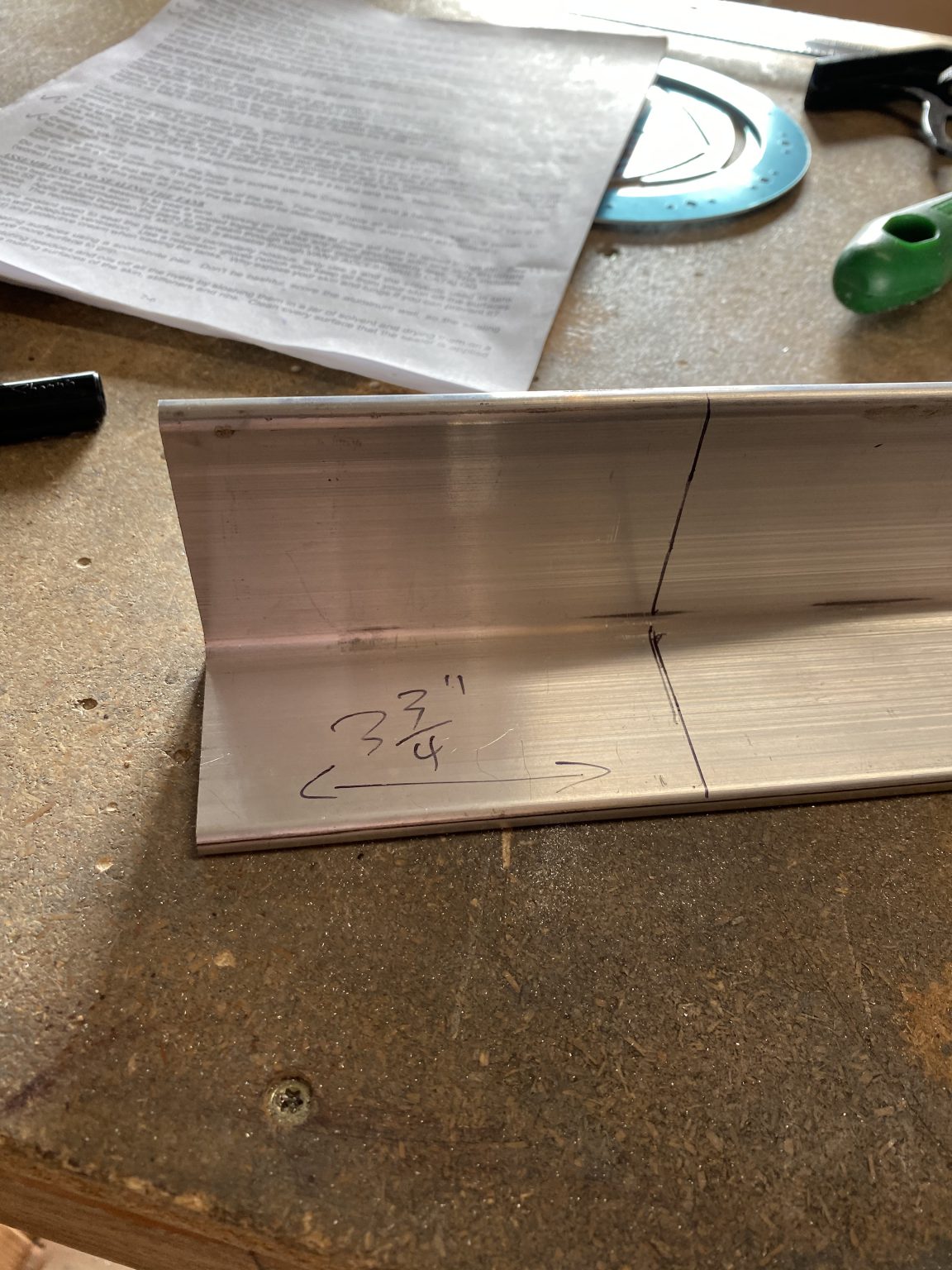
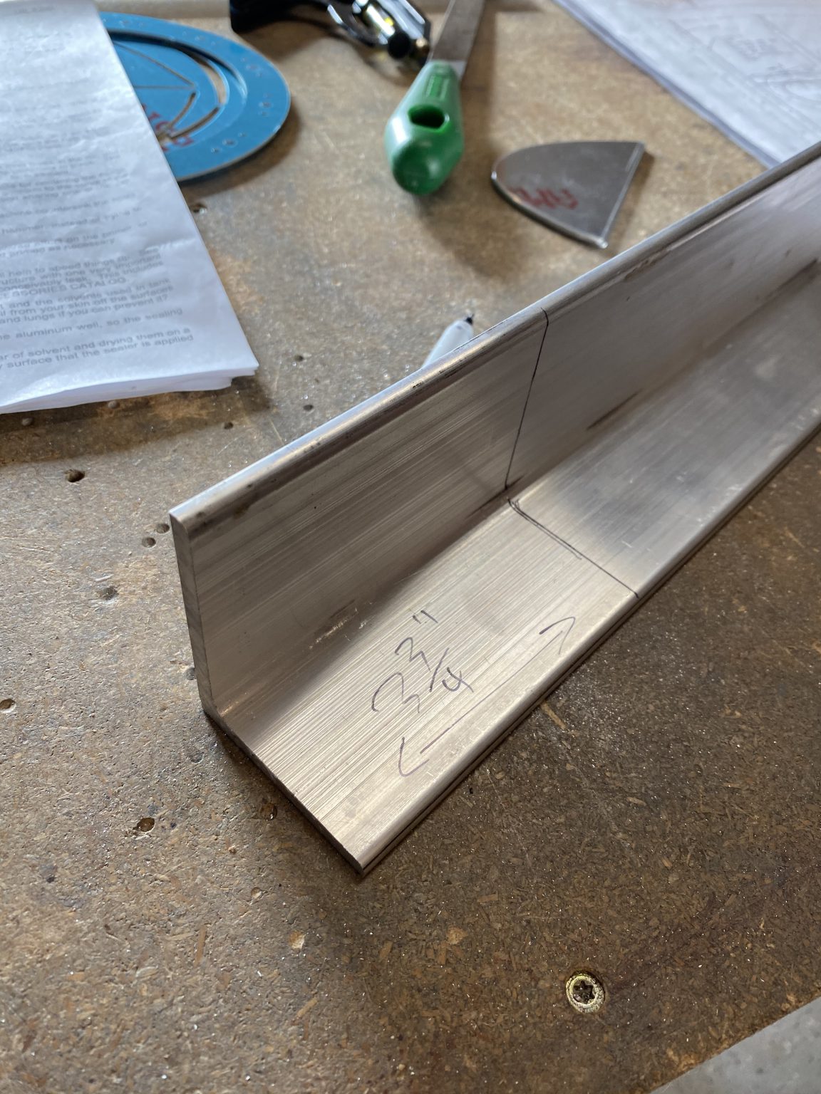
So I went digging in my parts shelf and pulled out the 2 x 2.5″ 3/16 angle stock that Vans includes in the kit. Then I marked off a 3 and 3/4″ section and cut it out on the band saw.

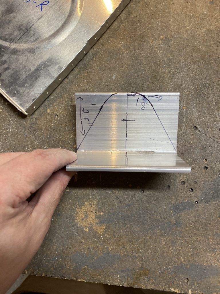
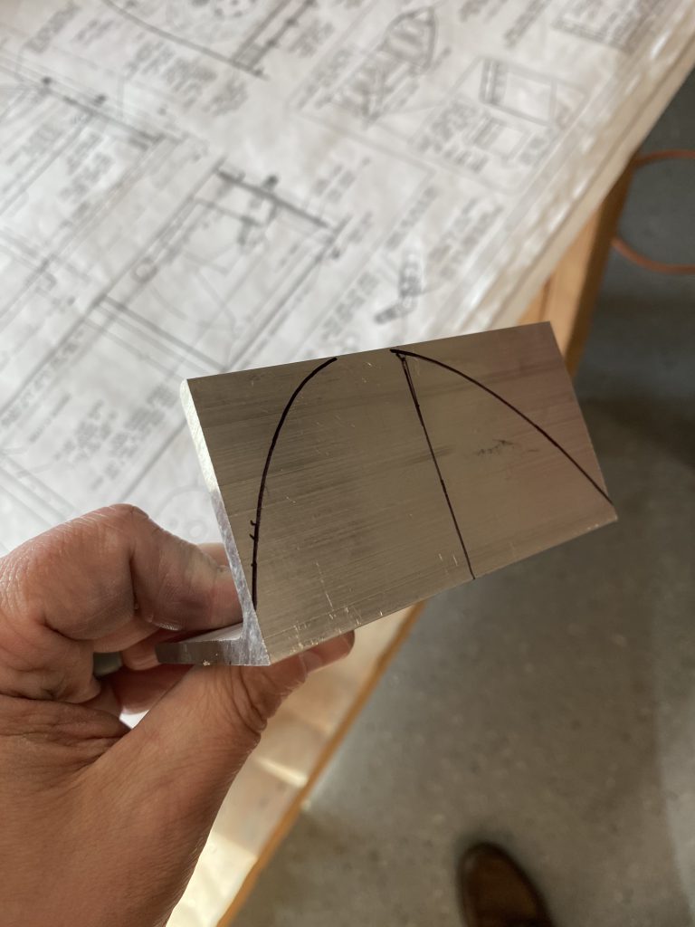
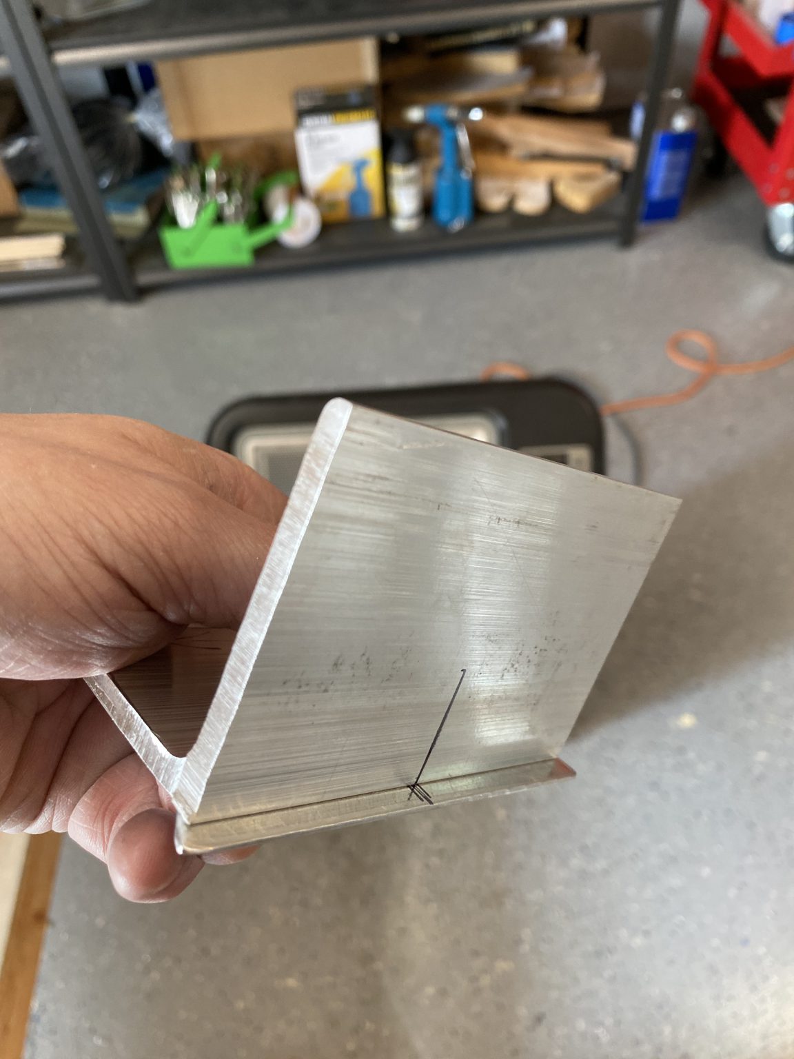
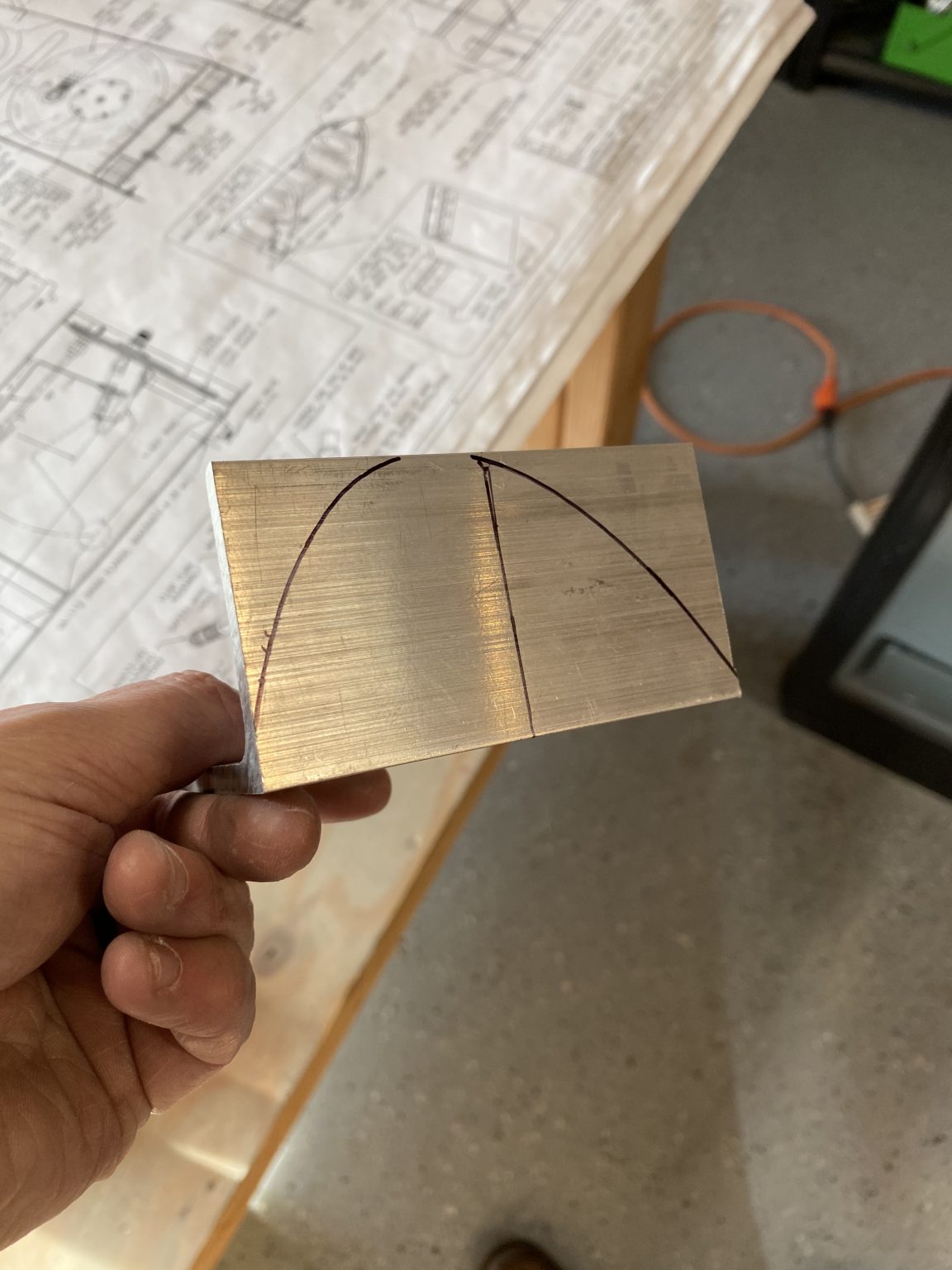
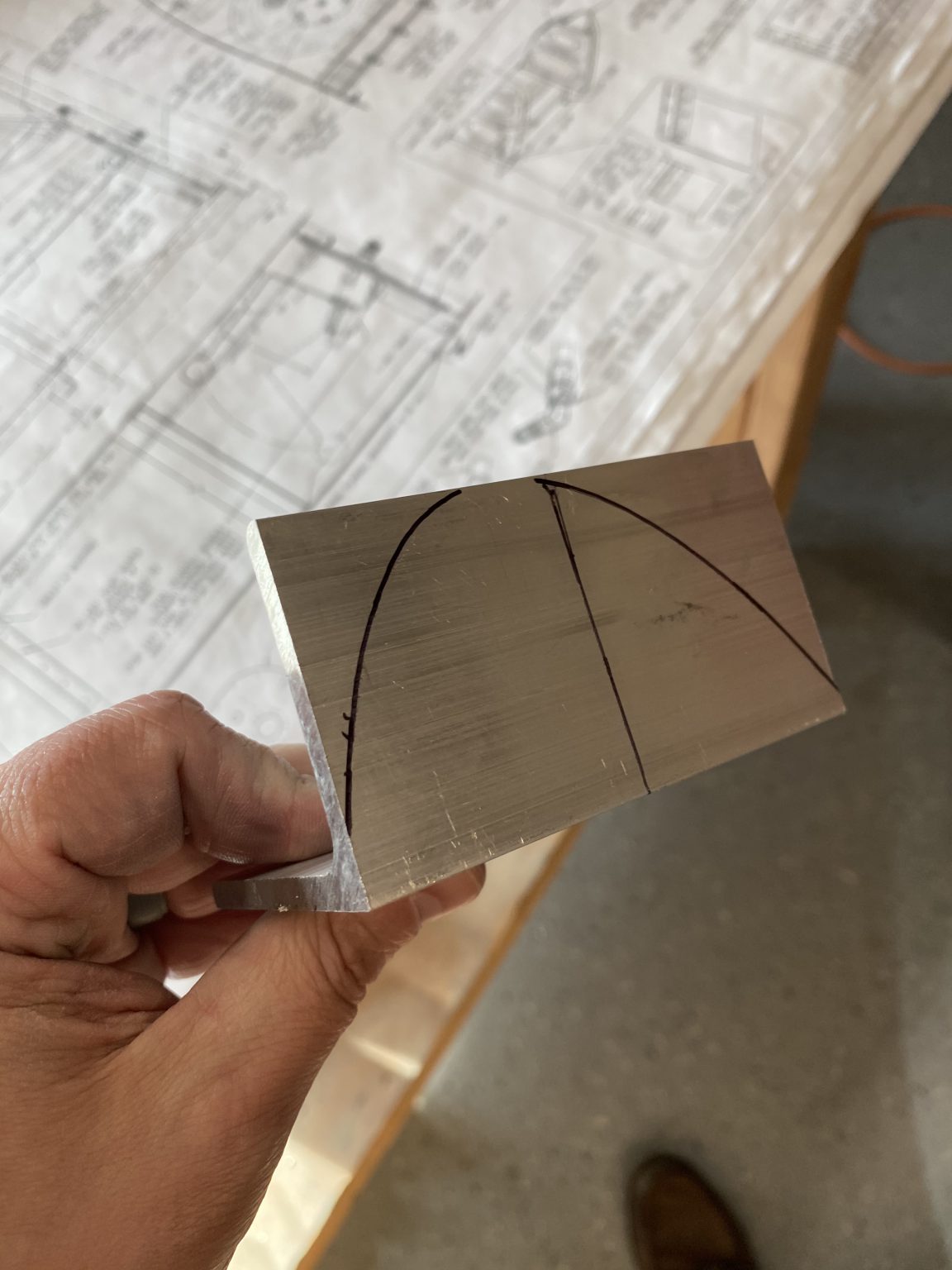
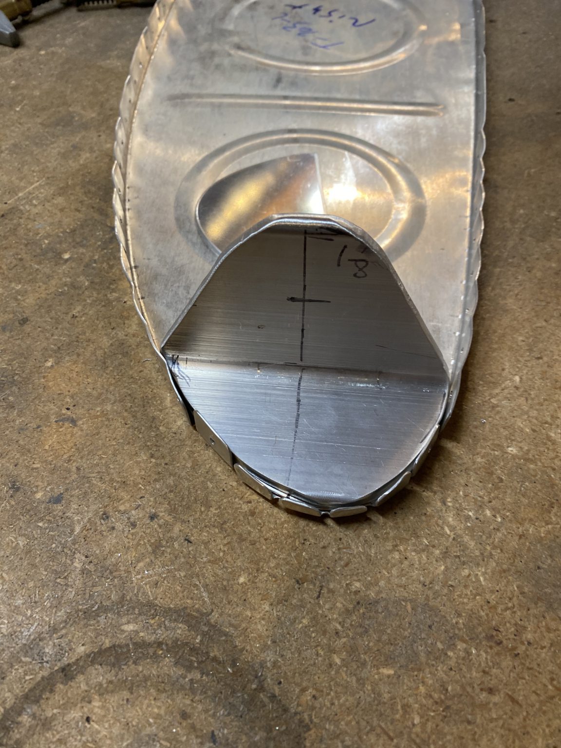
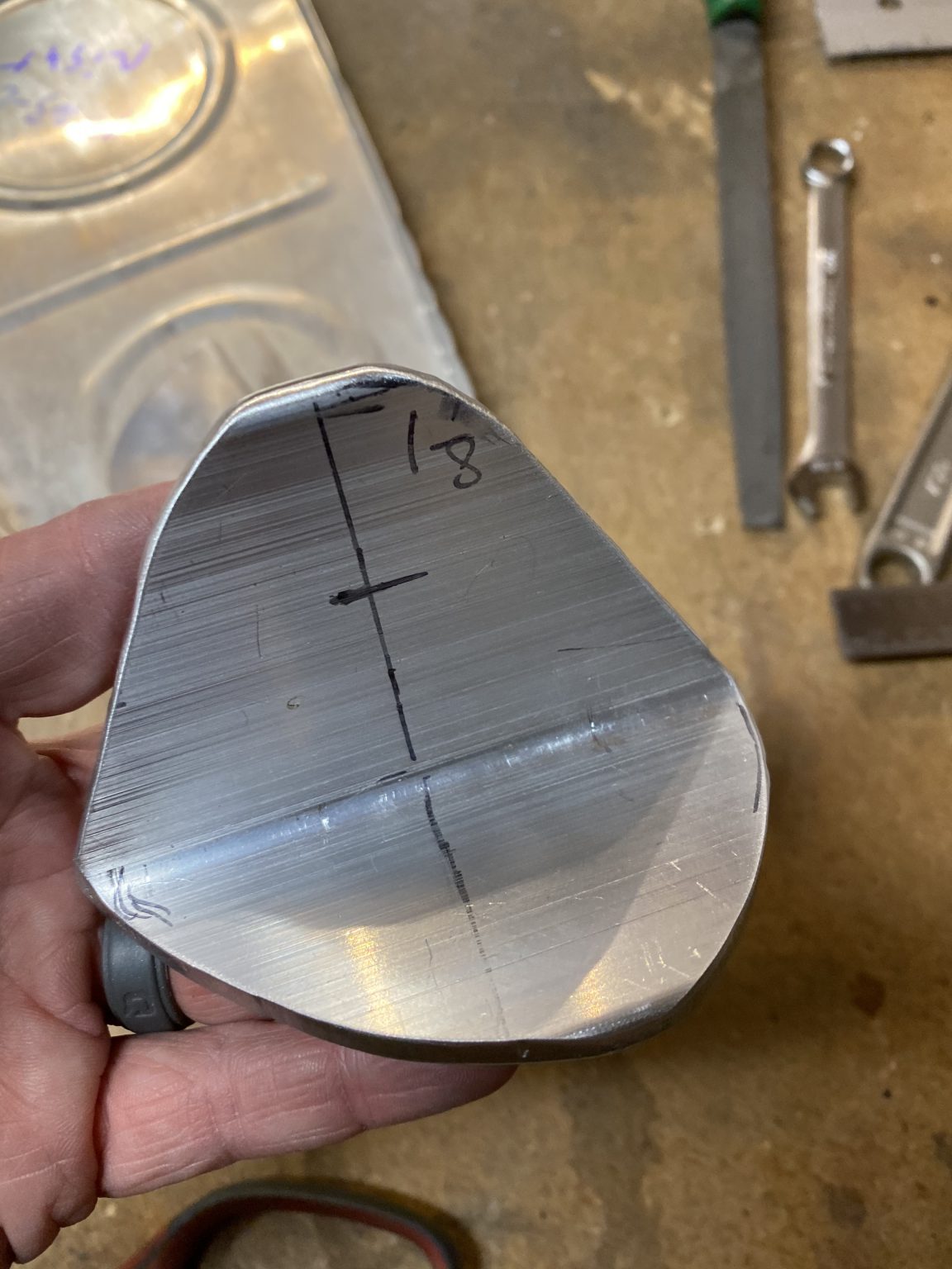
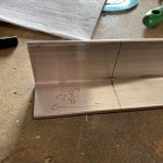
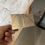
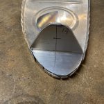
Next up, I wanted to cut the radius part out. This is the part that goes onto the fuselage to bolt the tank on to the aircraft, and after reading a few other builders blogs, it appears there is some flexibility in how these are mounted so we don’t have to worry about alignment issues per se. To cut the radius, I first marked off the center of the bracket as a reference. Then I measured the 1″ radius as the plans call for as “R1″ by marking down from the tip of the bracket 1″ This gave me a crosshairs to form my 1” radius around. I placed the point of a compass on this crosshairs, and started at the top of the bracket and marked with my compass until I was slightly passed a 45 degree angle on each side of the middle line. This is sort of eyeballing. Once I had a rough radius, I simple used a straight edge to mark from the stop of my radius down to the corner of the bracket. It looked like a good angle when I marked it all up, and it looked very similar to what the plans was calling for. See for yourself:
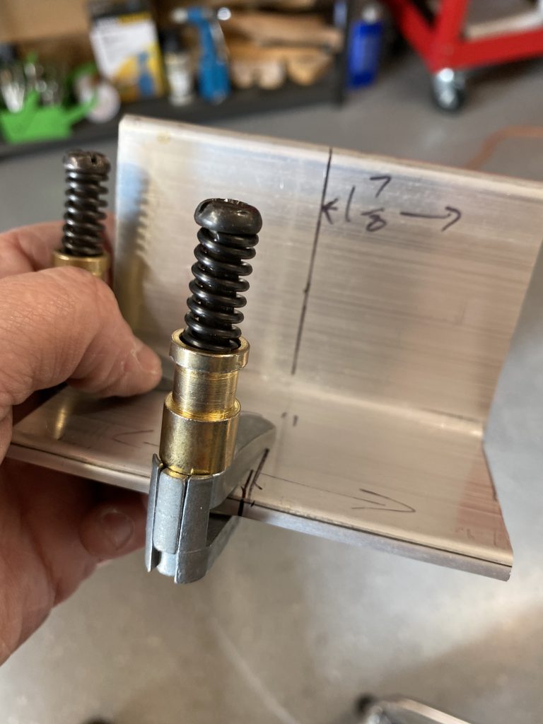
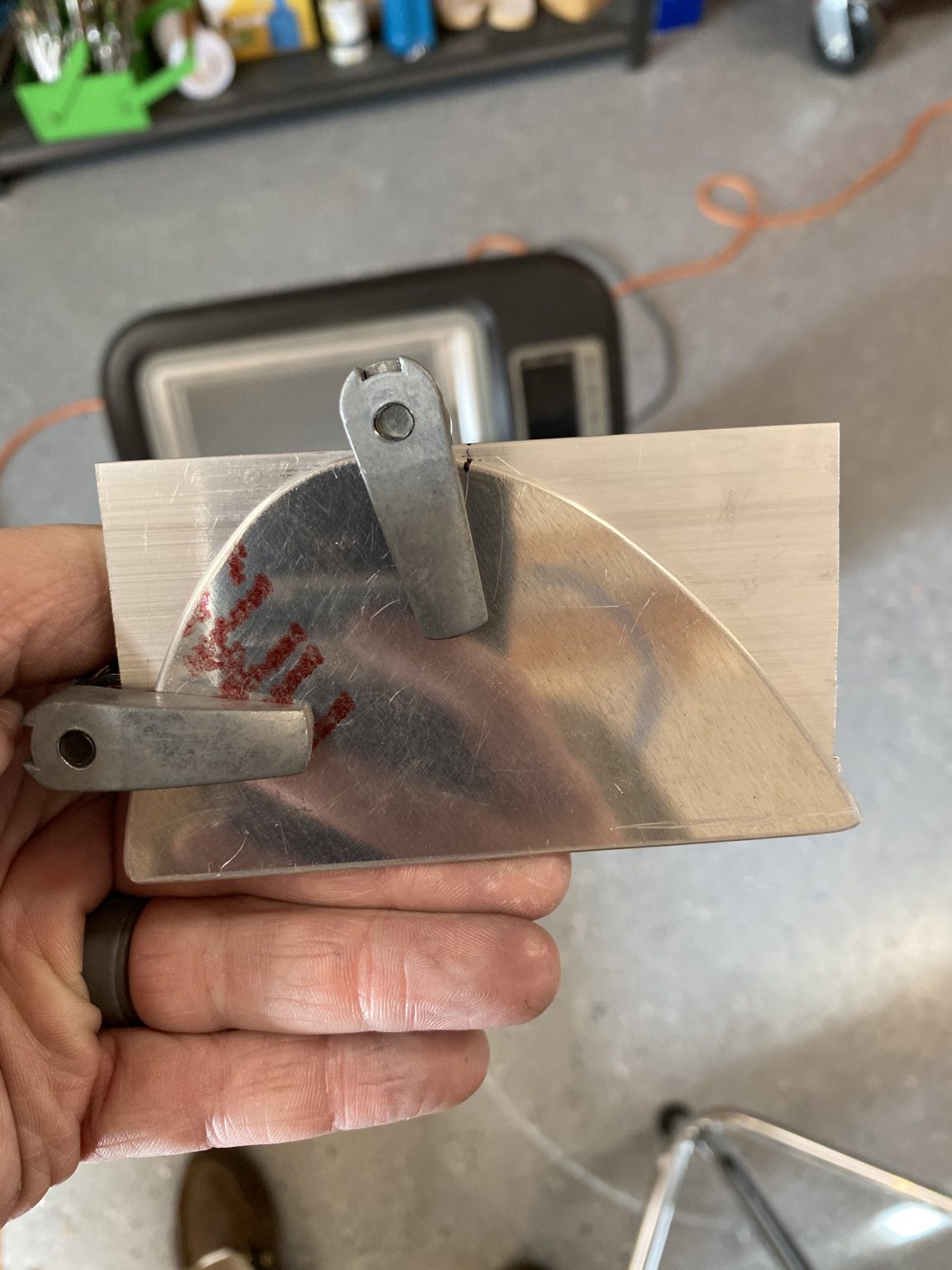
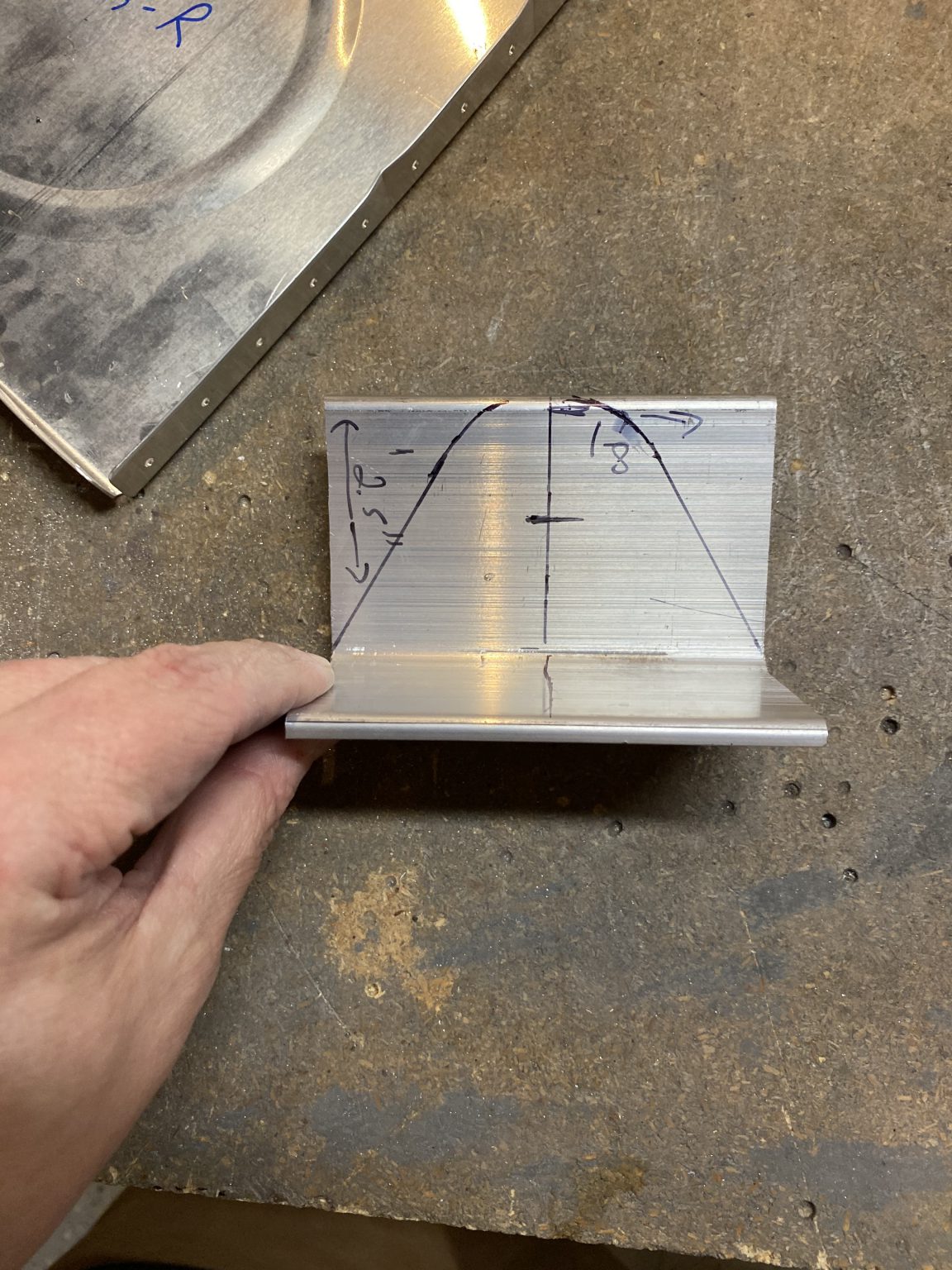
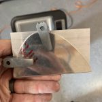
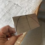
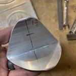
That took care of the TOP portion of the bracket, but I still needed to mark the bottom portion so it would fit snug against the curve of the ribs. Vans gives us a T-410 reinforcement plate that is already cut perfectly, and it makes a very nice template to use on the tank angle brackets. To make sure everything was squared up, I found the center of the T-410 to be right at 2″, so I marked the centerline of that bracket. The T-405 angle bracket is slightly smaller, and its center line is at 1 and 7/8″ as seen in the plans, so I marked that centerline on the angle bracket. Next it was just aligning the centerlines of the T-410 and T-405 to make sure they were squared up and in the proper orientation, and then use the T-410 as a template to mark my cuts for the T-405 angle bracket. Here you can see how I did this using some cleco clamps to hold everything.

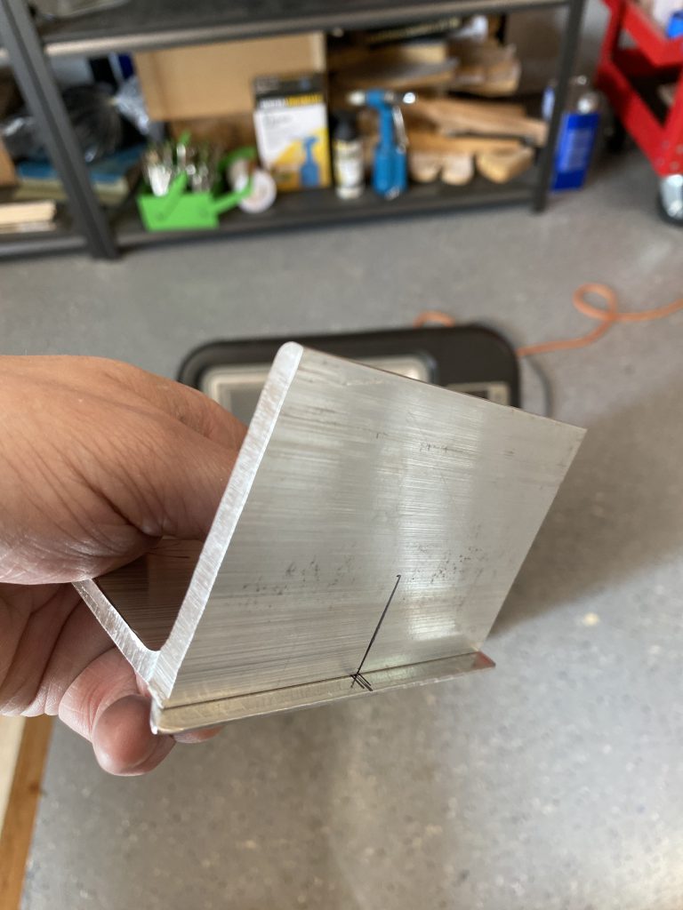
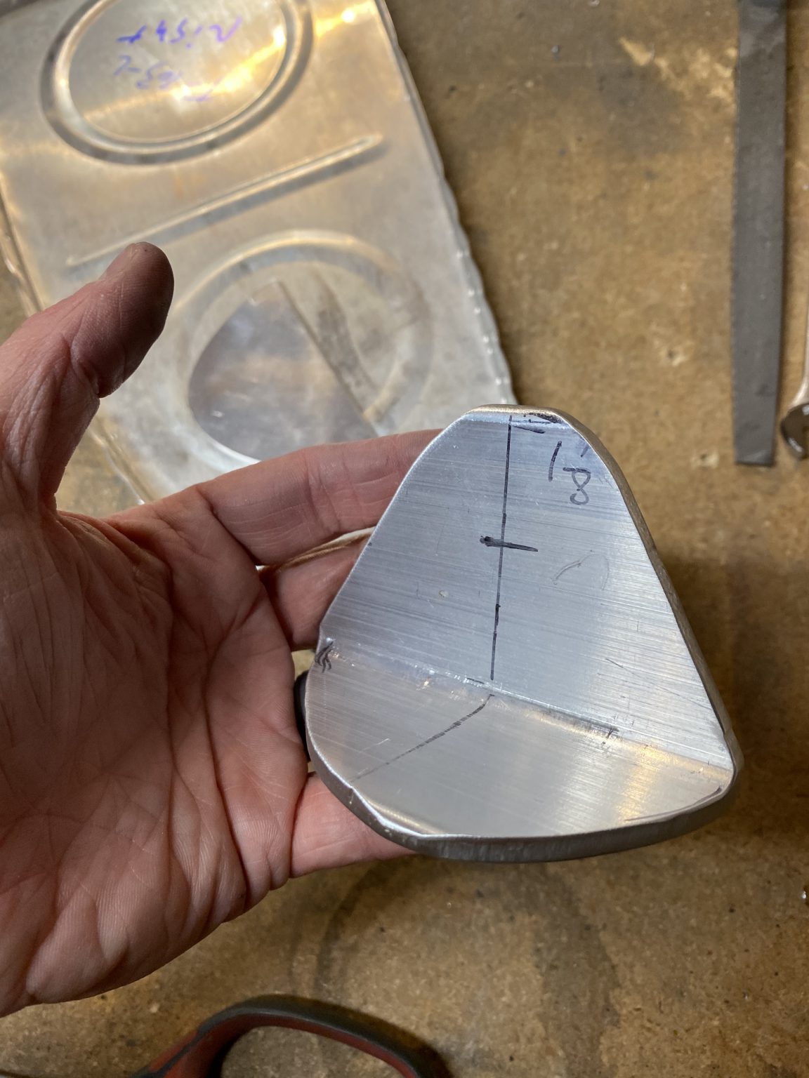
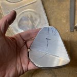
And here is what the copied line looks like on the T-405 tank angle bracket after you remove the reinforcement plate that was used as a template.
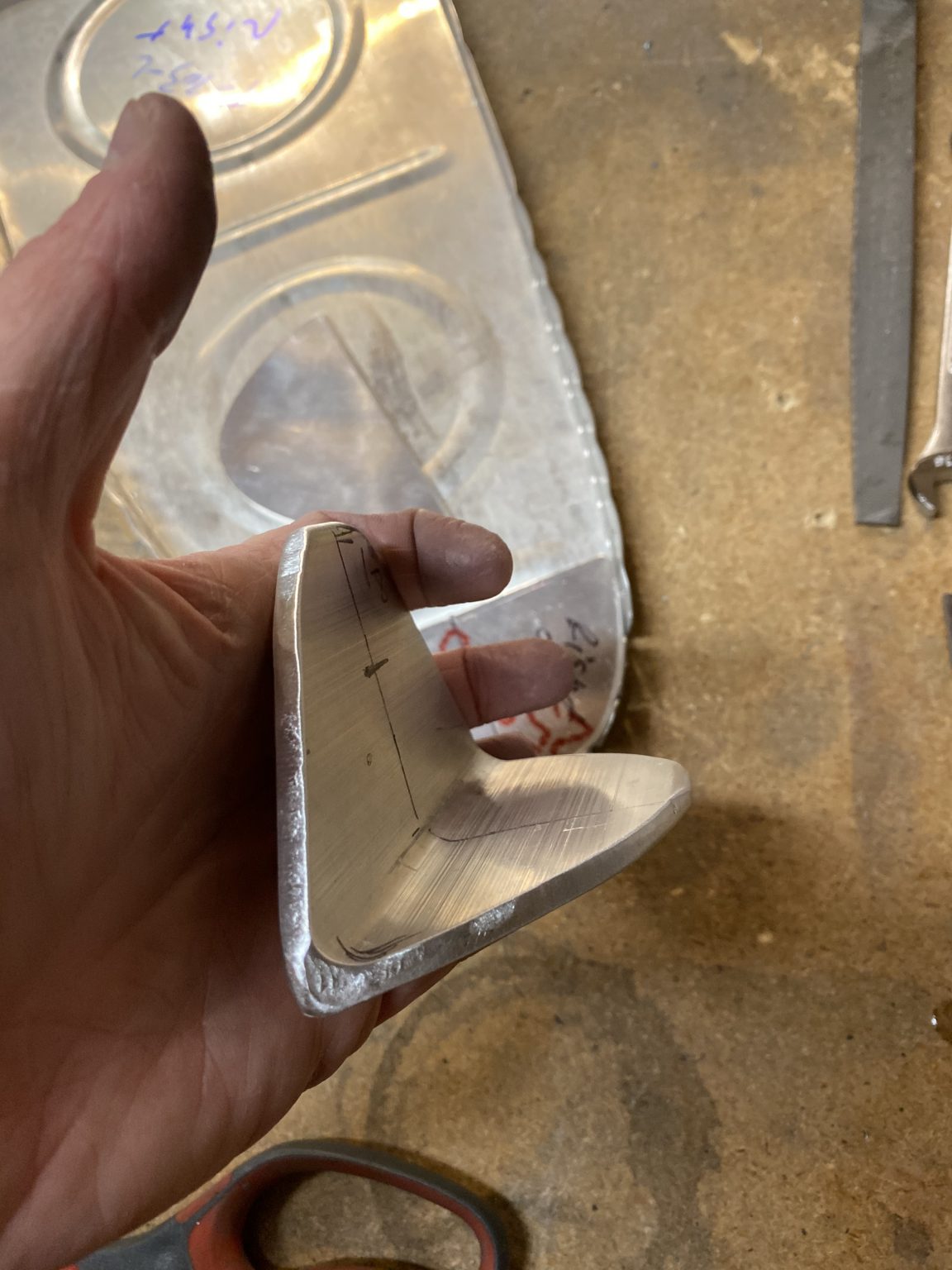
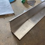
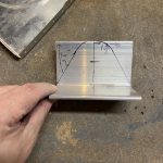
The next step was to cut these parts along my lines on the band saw. I used a scrap piece of wood 2×4 to help hold the angle and keep my hands clear. I wished I had gotten some photos of this process, but I didn’t have any free hands, and I was concentrating on making these cuts. However, its pretty simple and easy to do on the bandsaw, but I’d recommend not letting these be the first thick pieces of metal you make a curving cut on a band saw with if you have no experience. I’m not a novice with a band saw, but I have made some complex cuts with one on metal, just take you time and go slow so as to not bind the blade. Remember you can always work you way into the cut pieces at a time if you need to. I also started OUTSIDE of my marked lines, so I’d have a little extra material to work with on the grinder to finish with. After I had my rough cuts made, I finished up the parts on the grinder, working away the extra metal until I was right at my marked lines. Here is what it looks like:

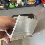
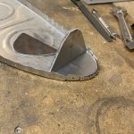
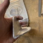
And after a few test fits, and visits back on the grinder I had a part that fit fairly good! Once I was happy with the fitment, I went back to the grinder and rounded and smoothed all of the edges for the T-405 tank attach angle brackets. These look like some sort of machined part with the crazy curves they have, but its a simple angle cut and smoothed 🙂
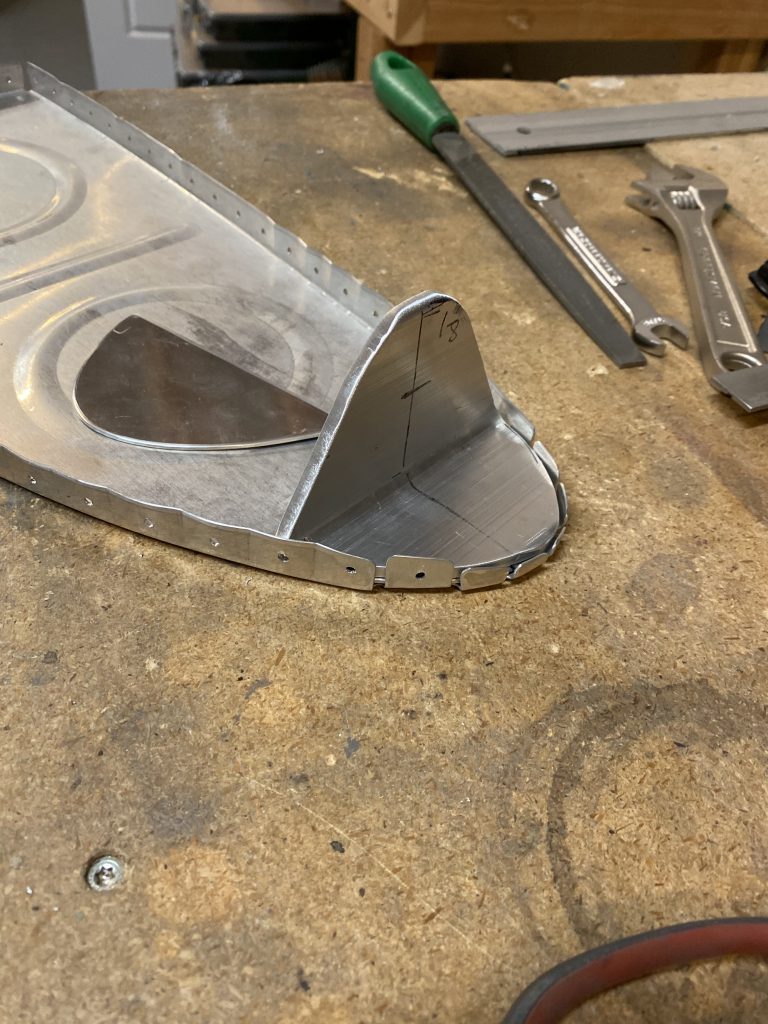
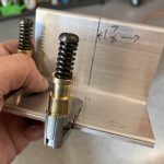
The only thing I am worried about is how I am gonna get to the rivets in the holes around the edge of the brackets (see photo above). There isn’t much room for the rivet tail in there between the flange inside and the tank angle bracket. I’ll do some research and see what other builders have done, as well as read ahead in the plans to see if this is going to be an issue. It may be that I just notch out a little section for the rivet tail to fit into and call it a day. After getting one bracket made up, I went ahead and moved on and did the same thing for the right tank brackets. These were pretty much mirrored of each other, so the second one went a little faster than the first. The plans tells us to go ahead and drill the rivet holes for these parts (T-405 angle bracket, T-410 reinforcement plates and the T-703-L/R ribs), but I am going to wait on that until I am sure about what I want to do about notching them first. I’ll call it a night for now.
-
 IMG_0693
 -
 IMG_0694
 -
 IMG_0696
 -
 IMG_0695
 -
 IMG_0697
 -
 IMG_0698
 -
 IMG_0699
 -
 IMG_0700
 -
 IMG_0701
 -
 IMG_0702
 -
 IMG_0703
 -
 IMG_0704
 -
 IMG_0705
Google Photos Link: https://photos.app.goo.gl/77eEx2AzRojMogfLA
Hours Worked: 2.0