


This is going to be a long blog, with lots of pictures. So sit back and get ready. I got a LOT accomplished today. It started with the arrival of a few tools I needed. A nibbling tool, and a Tekton 1/4″ torque wrench. I wanted to get the Gretz Aero pitot mount installed, and the hole for it cut in the left wing before I riveted on the top skins. Here’s the ovehead timelapse of the work:
And here is a closeup view, that I moved around the shop as I worked to get a better view of what I was doing:
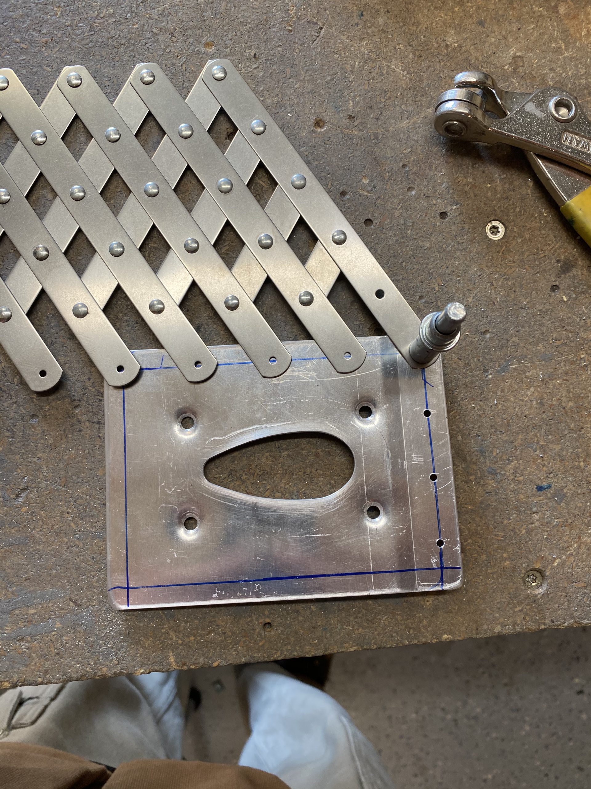
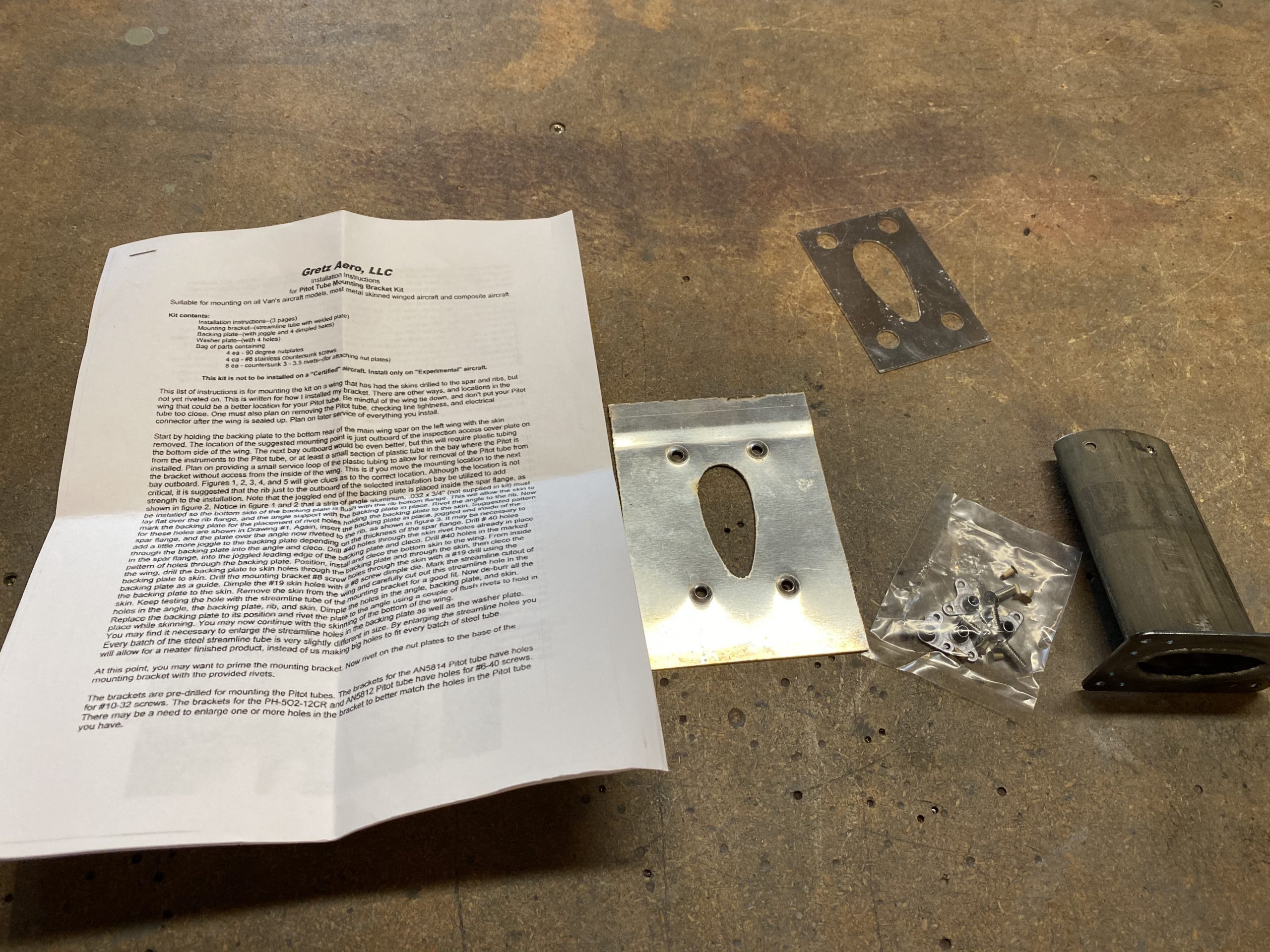
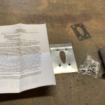
So, lets dig in to the details. I took a lot of photos because there is a lot of “custom work”, outside of the normal Vans plans, since Vans only has you use a small piece of aluminum tubing for the pitot. I decided to go with a nice heated pitot that has an AOA sensor in it as well, since this airplane will be used for IFR work. I elected to go with a Gretz Aero pitot mount, because I like how the mast screwed in to the wing via reinforcement plates. This makes the entire pitot assembly (tube and mount) fully serviceable in the future. In the end, I really like the Gretz mount and highly recommend it. Here’s what you get in the kit:
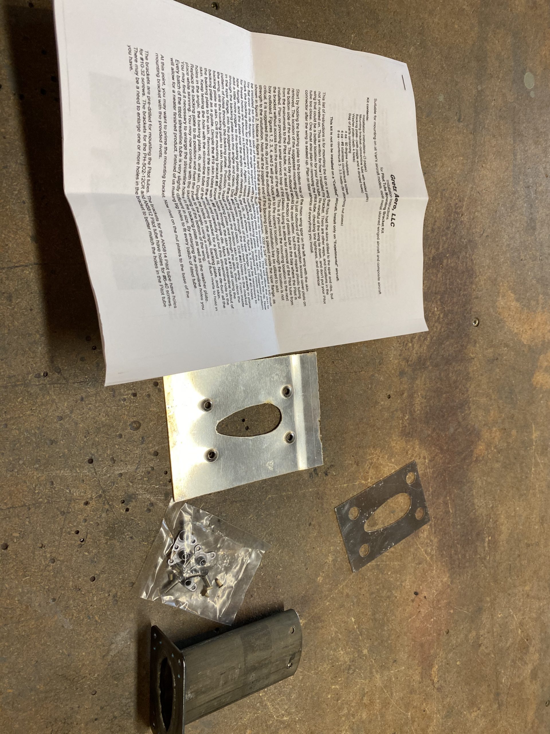
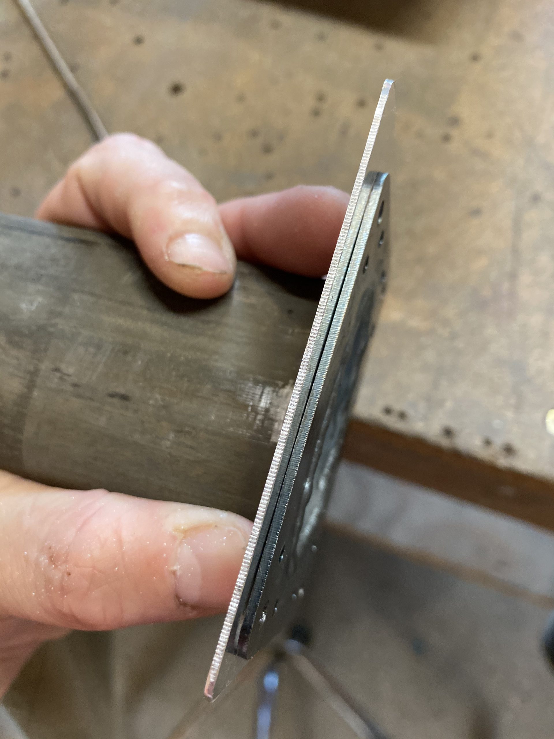
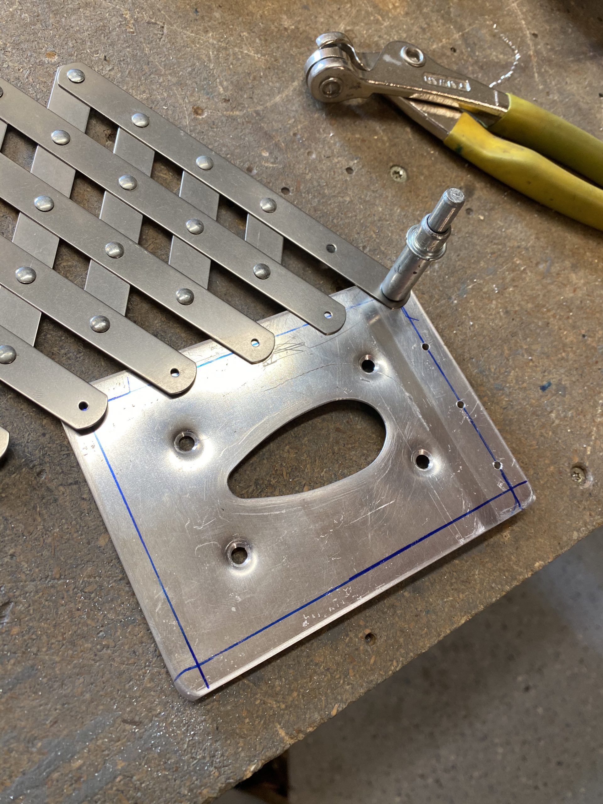
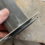
The instructions are pretty decent, and I gave them a good read before starting this session, since the mount came in a few days ago. Gretz tells us we may need to file down the openings in the reinforcement plate and washer plates due to slight manufacturing tolerences in the mast itself. They also make these holes very close tolerance to give a very nice finish, but it requires a little filing work on the customers end. I actually like this, as I ended up with a very tight fitting assembly that is going to look fantastic. I just had to use an assortment of files to get the mast tube to fit in the plates first. A half-round bastard file was what I used most, followed by some small round files.
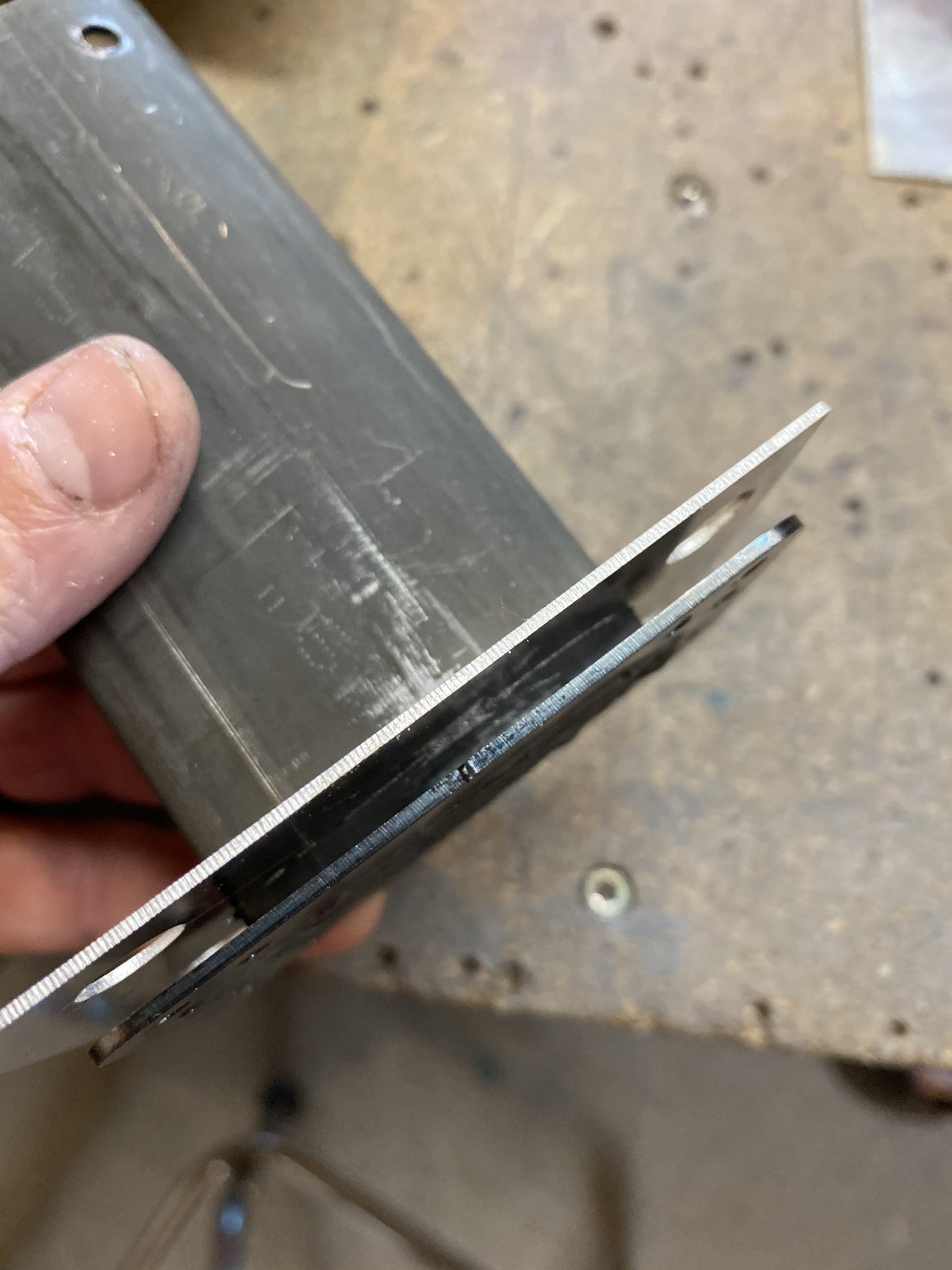
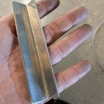
There was a lot of gentle filing, test fitting, filing some more, test fitting, etc, etc, etc. But eventually I wound up with the pitot mast fitting very snugly into the plates:
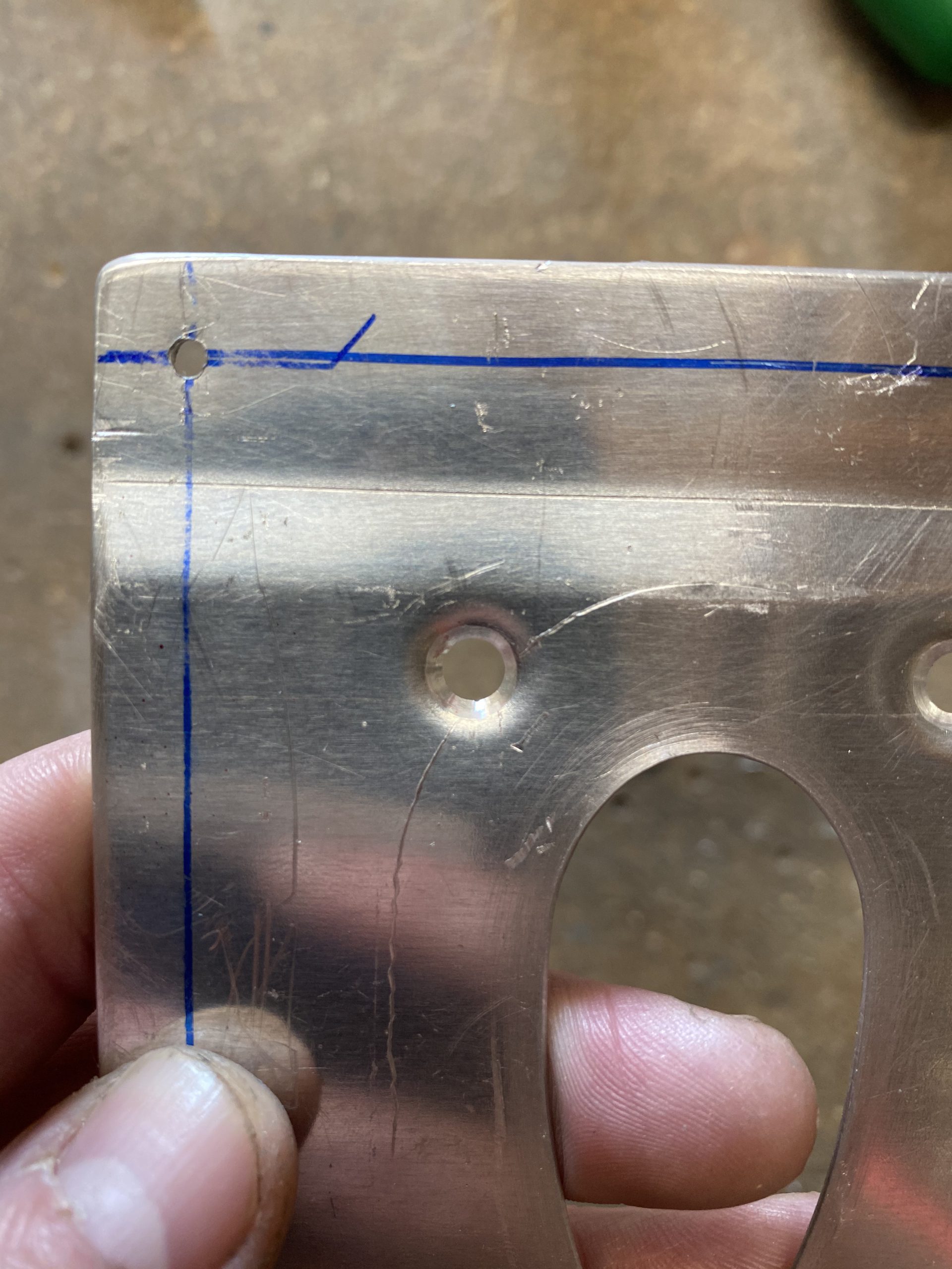
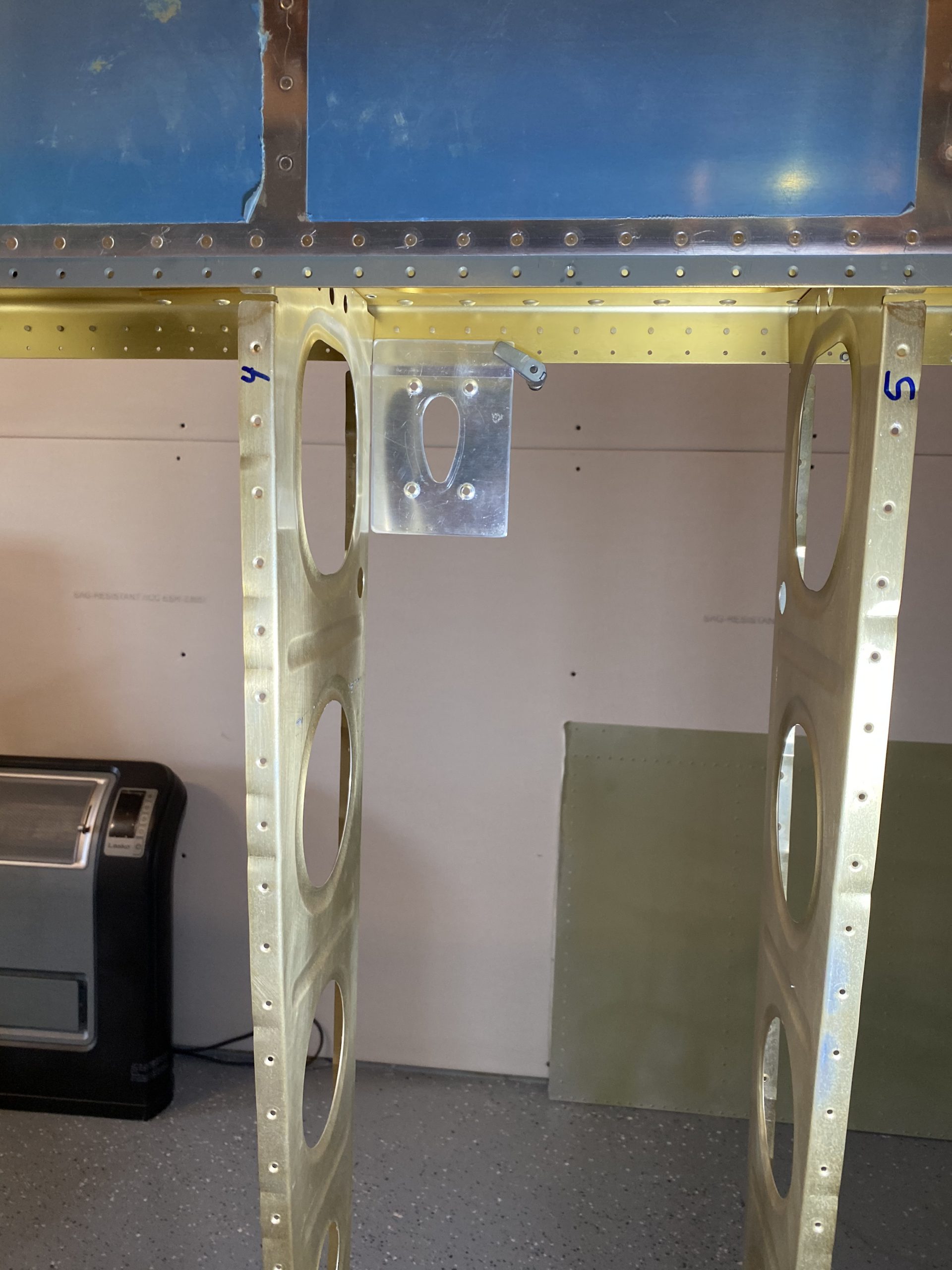
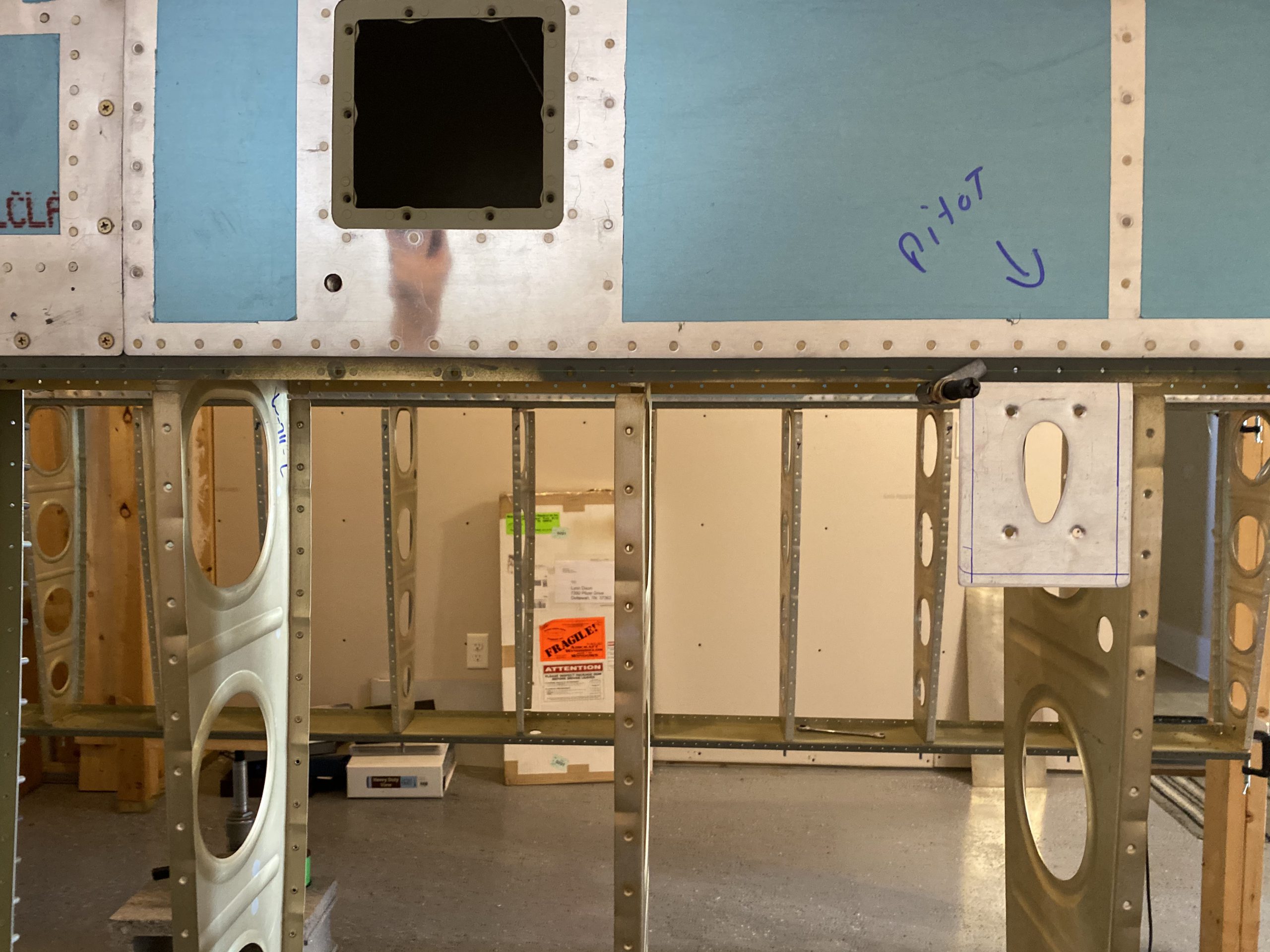
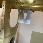
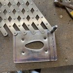
Next, its time to fit the reinforcment plate (the one with the little joggle on it) to the wing skeleton, and start drilling some holes. The plate does not have any rivet holes, as its designed for the builder to fit it whereever they want. I chose to mount my pitot just one bay outboard of the access hole for the aileron bell crank. This is pretty typical of most RV-7’s, and I figured if it works well for all the others, it should me too. Its far enough away from the tie down ring it shouldnt be a problem, and also close enough to the access hole I can easily service it if needed. The reinforcment plate was designed for a Vans RV airplane, so the joggle on it was just perfect, with only a little forming needing to fit snug. Next, I measured where I wanted the rivet line to be. I found the center of the joggle, and marked the rivet line with a sharpie, and used this same distance for the other three sides as well. I then used a Noxon center-punch to mark the first hole location for reference.
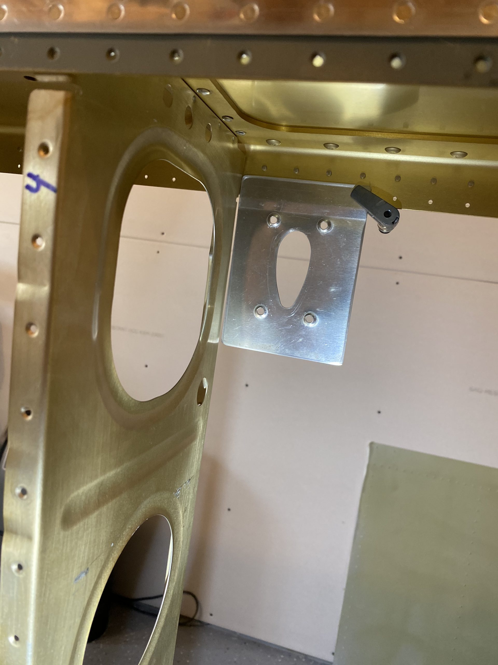
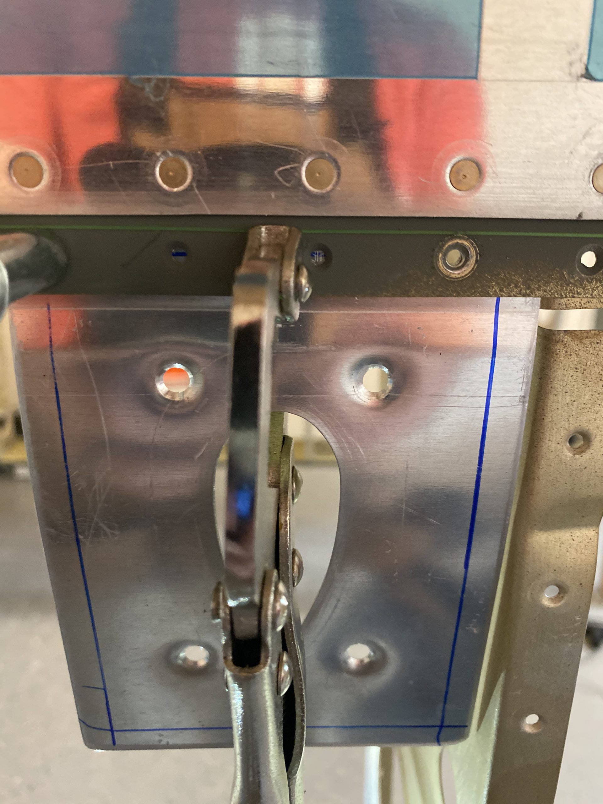
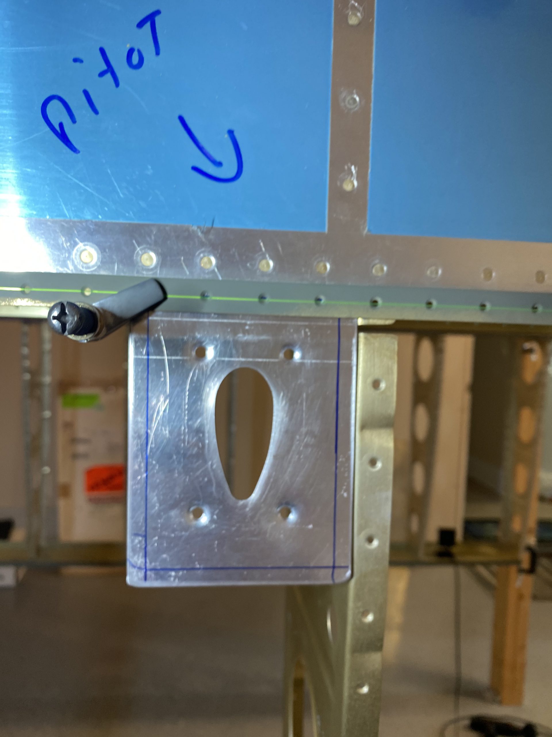
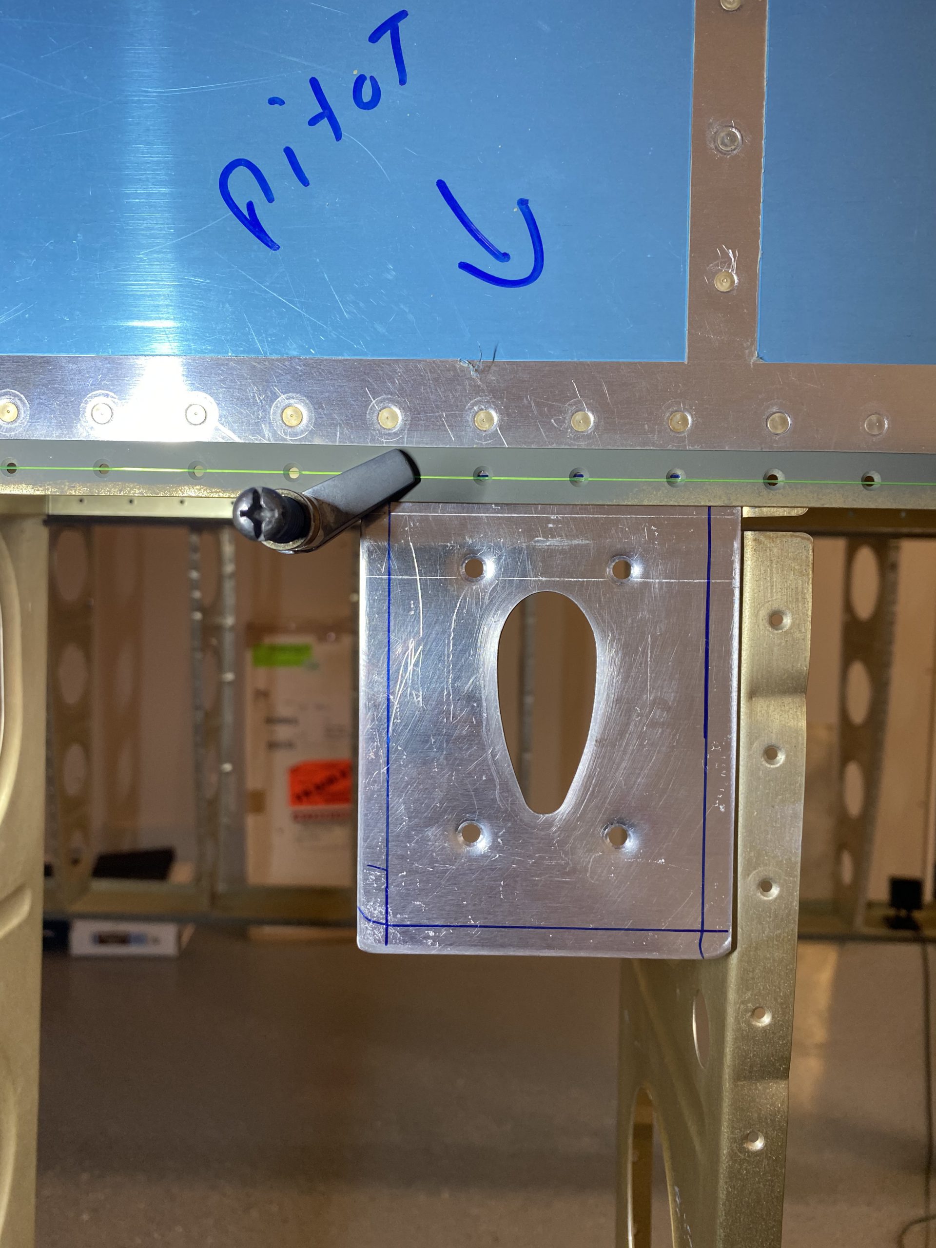
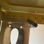
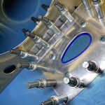
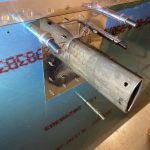
I wanted to verify the lines on the joggle part lined up nicely on the spar flange, and that I didn’t have any interference issues, so I grabbed a cleco clamp, and clamped the plate on to the spar flange, making sure to line up the blue sharpie line with the rivet holes in the main spar flange, then I checked that I had plenty of clearance from the leading edge skin rivets. This looks good so far.
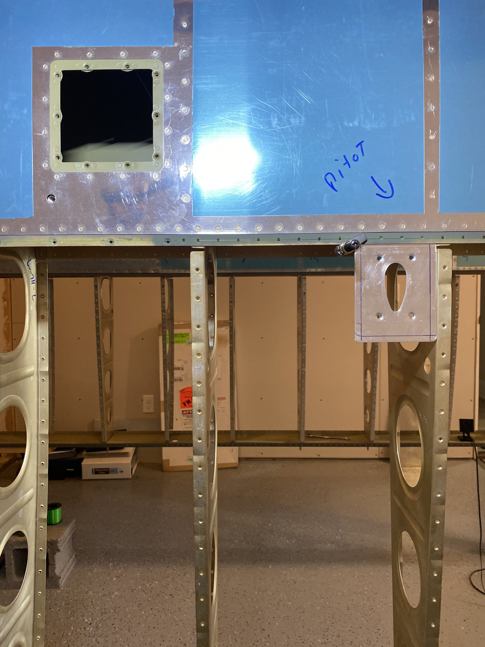
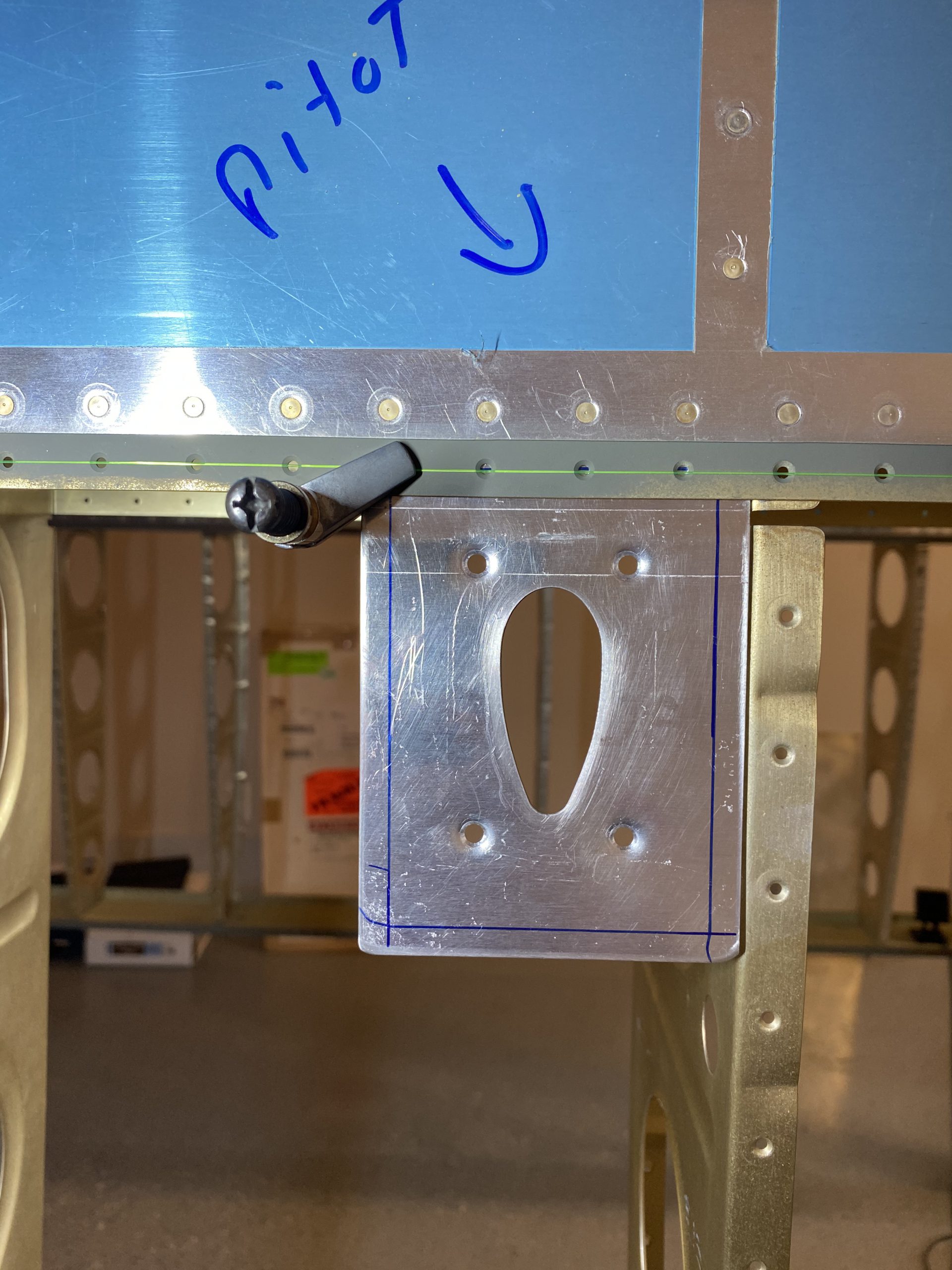
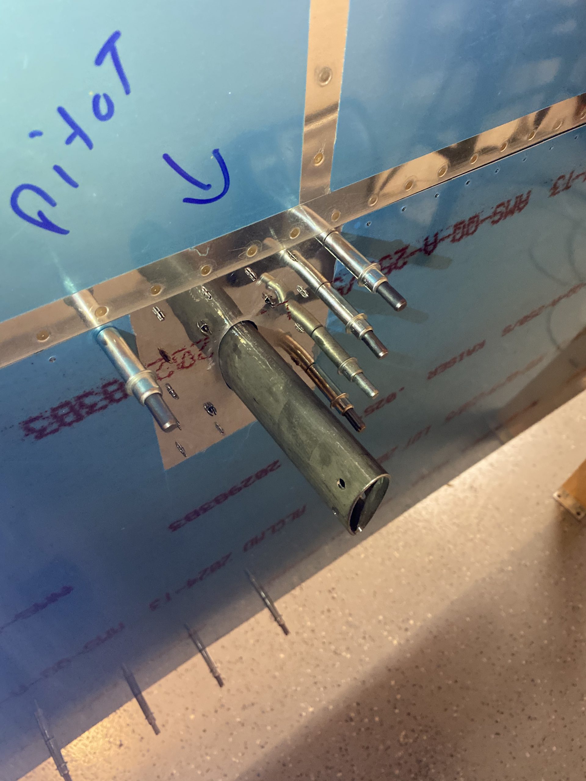
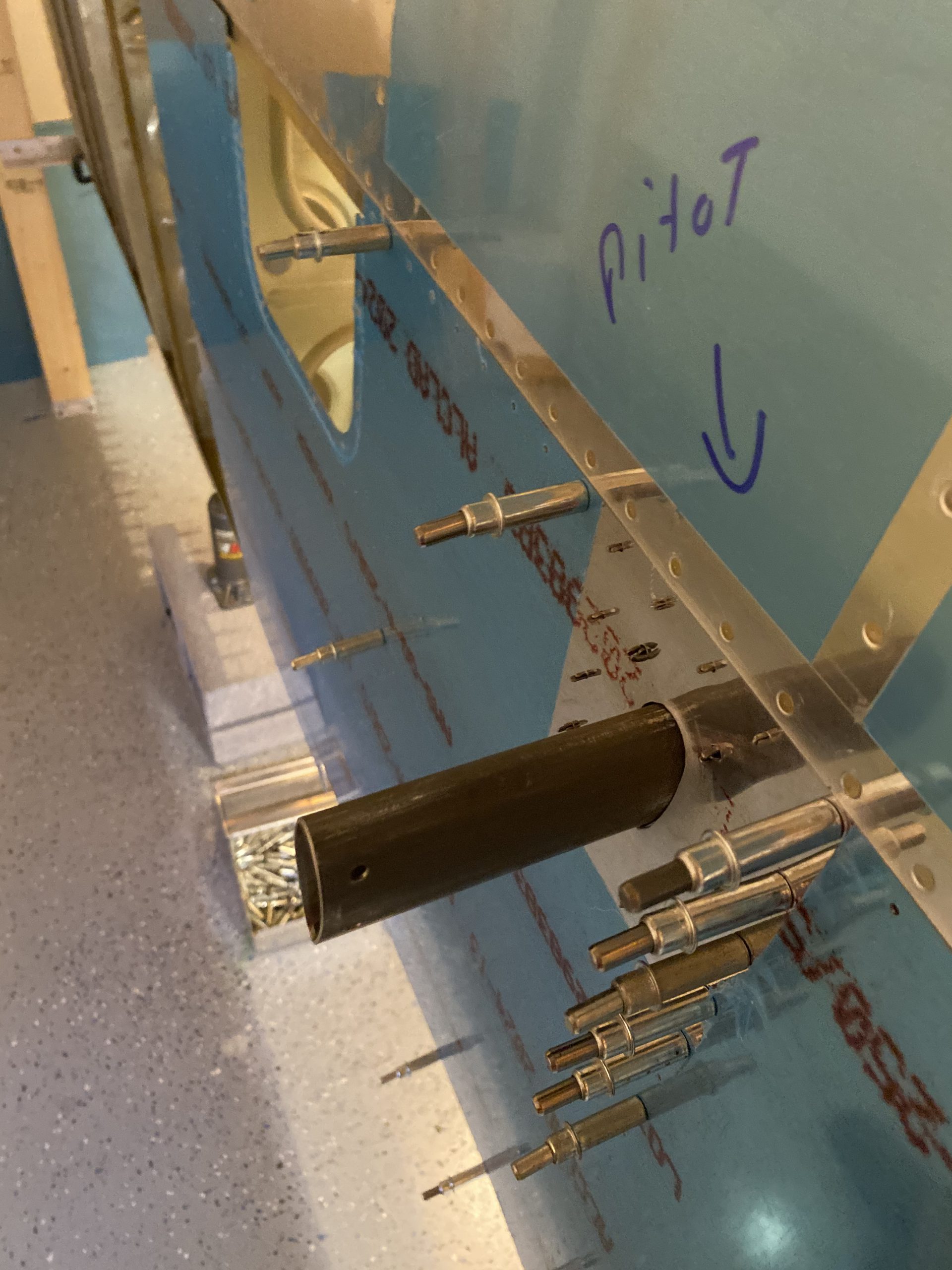
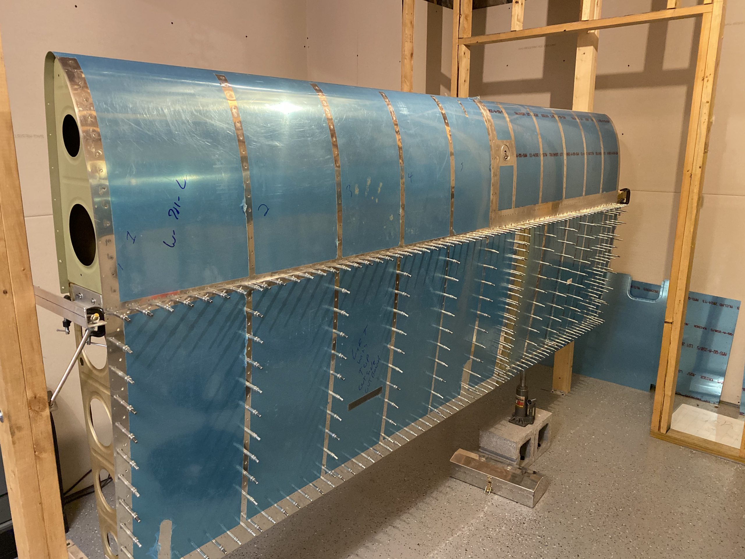
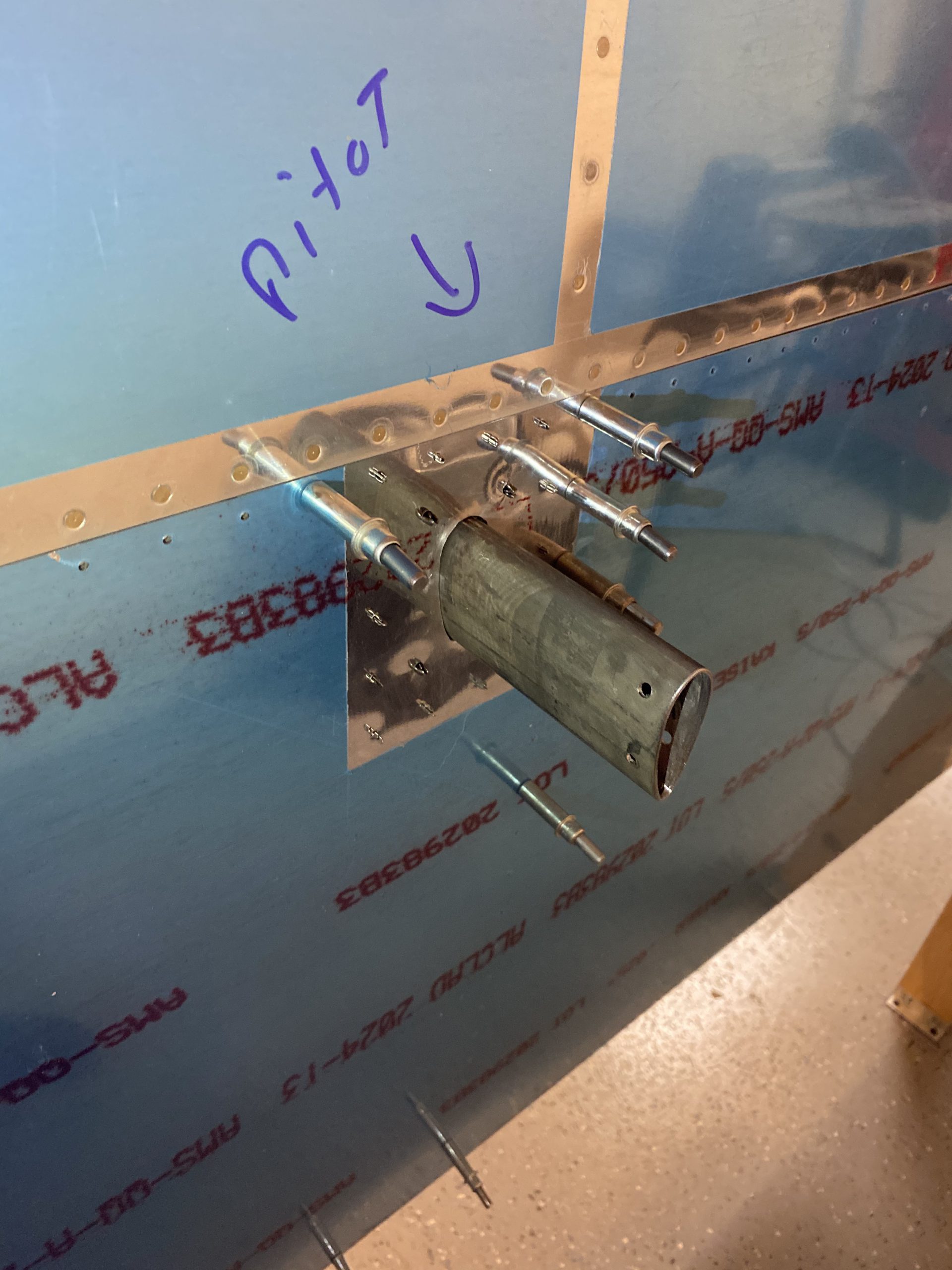
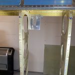
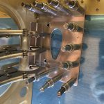
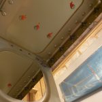
And here’s what it looks like from the bottom side of the wing. Yes, I did indeed write “PITOT” on my wing, so I would make sure I got it in the right rib bays. It also lets you get a better idea of where I am installing this thing on the wing.
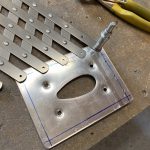
Happy with how its looking so far, its time to start drilling the holes into the reinforcement plate! Gretz gives us a rough layout of where the holes need to be, so I used that as reference on how to lay mine out. I used the spot I center punched to drill the first hole, then I cleco’d the reinforcement plate back onto the spar, lined up the blue sharpie line and then clamped it into place so I could back drill the other holes using the spar flange as my guide. Back drilling from the spar scratched some primer off, so I’ll need to touch that up, no biggie.
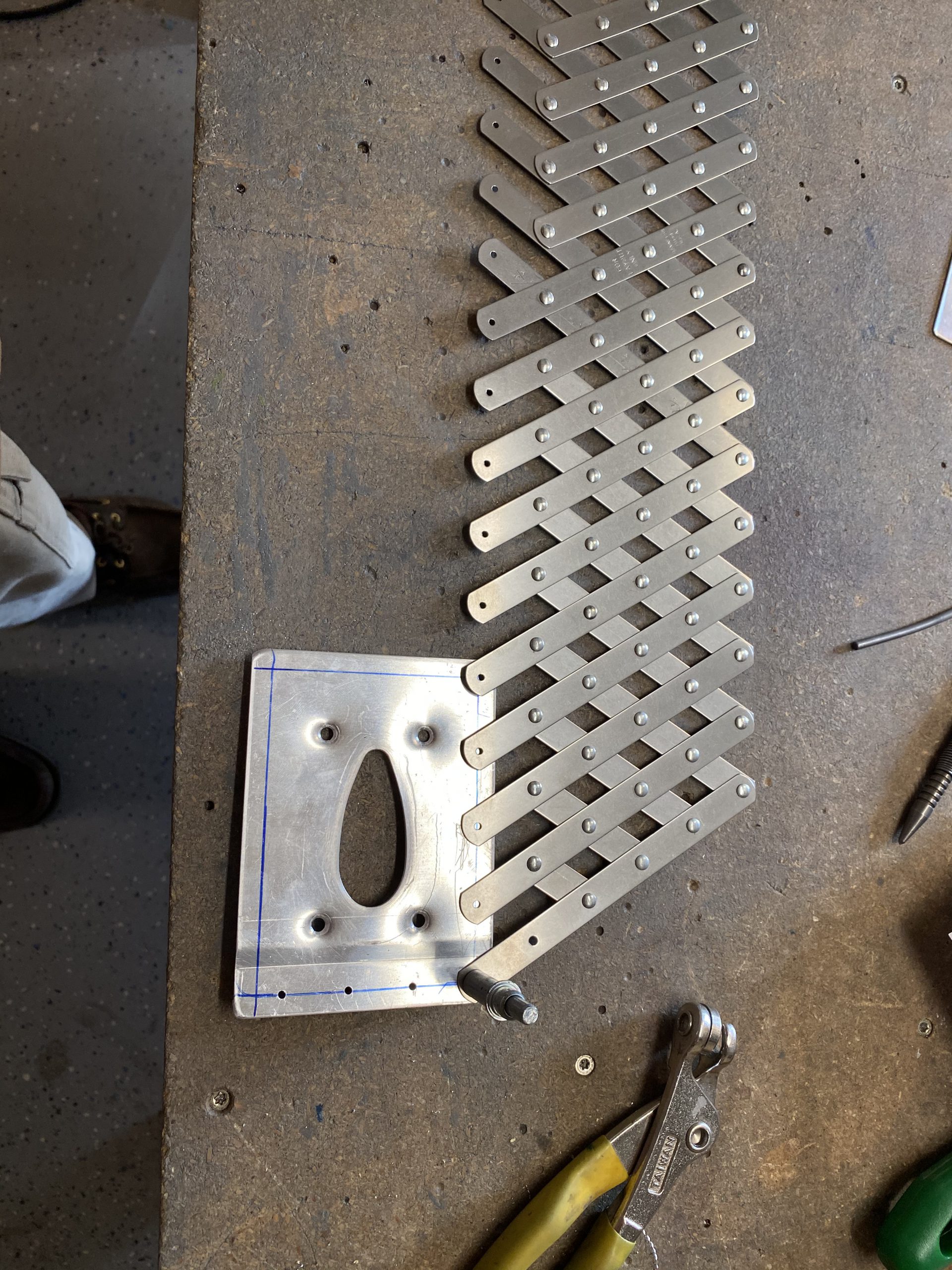
With those 4 holes done for the main spar flange on the plates joggle, its time to get the rest of the holes done. This was pretty easy as I used a rivet spacing fan to help. I’ve had this tool for a long time, but never really used it much, until tonight. It worked great. Its a nice tool to make very evenly spaced rivet holes! Using the outer hole I just drilled into the joggle, I clecoed the rivet fan in place, and spread it out until I had the 5th hole in the spacer lined up perfectly with my centerline I drew earlier. This gave me 5 very evenly space holes to use.
I center punched the end hole using the spacer fan as a guide, the drilled it with a #40 drill. To get the other three holes perfect, I clecoed the fan at both ends, and then center punched the other three holes using the spacer fan as my guide. Then I removed the fan, and drilled the holes to #40.
I just followed this same procedure all the way around the plate until I had all my rivet holes drilled and nicely spaced. However, Van’s used a different spacing on the spar flange, and I am butting up against the back of the rib so my bottom holes don’t line up exactly to my top holes, but thats only cosmetic, and wont be seen once its all painted anyways.
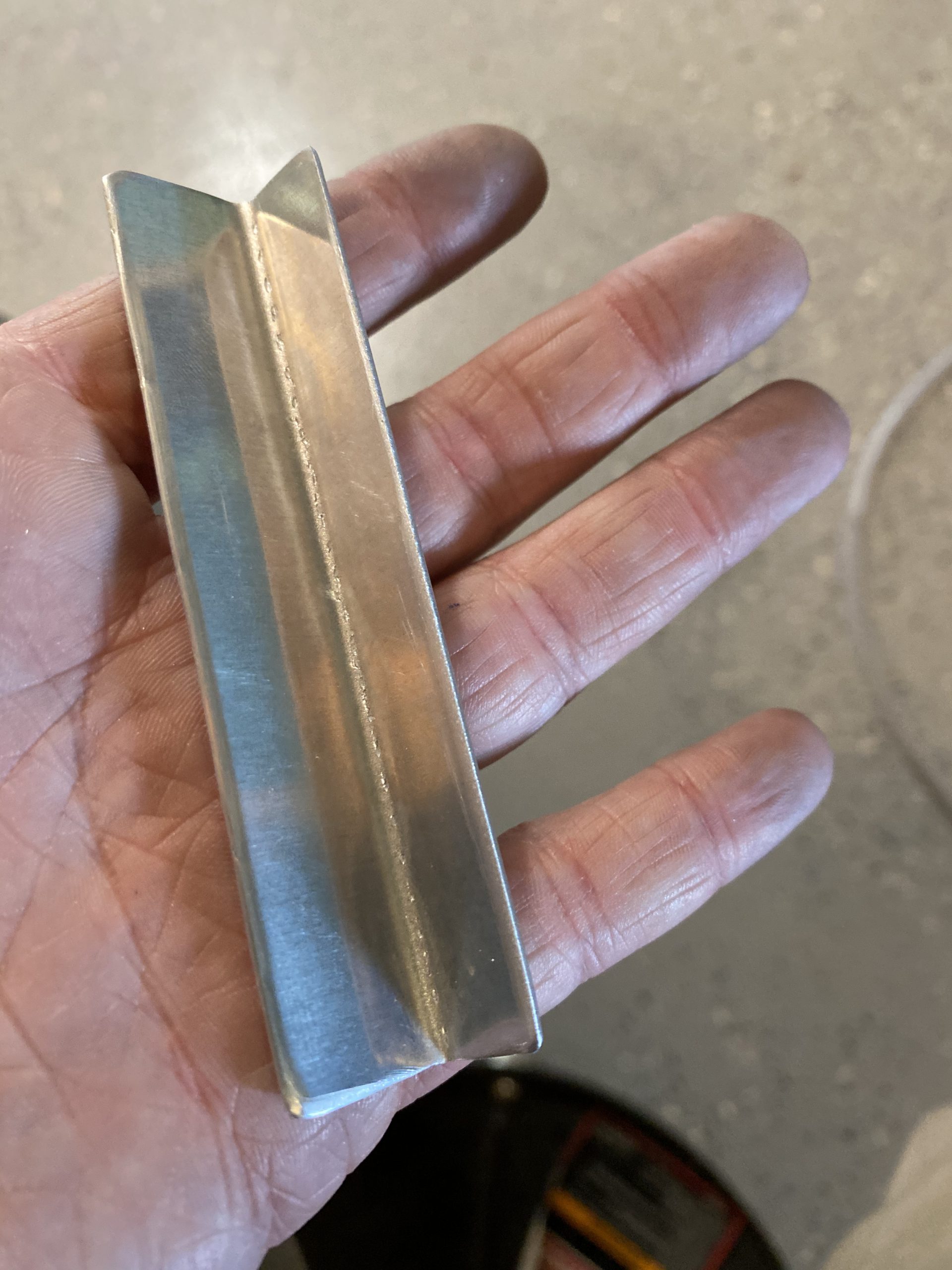
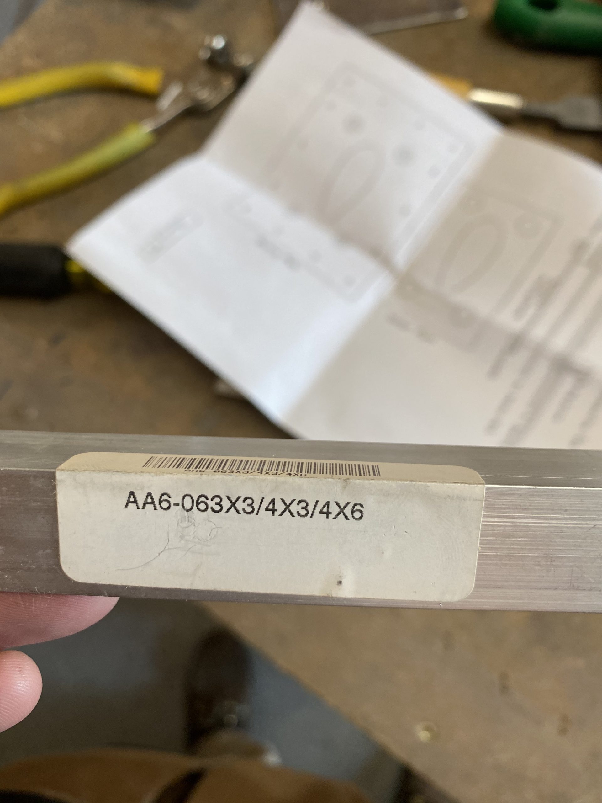
Now its time to make the small reinforcement bracket that is used to brace the reinforcement plate to the nearest rib. Gretz plans tells us to use .032″ to make the support brace / bracket, and luckily I had a sheet of .032″ in my scrap bucket to use. I clecoed the bottom skin to the skeleton, and then clecoed the reinforcement plate onto the spar flange so I could measure and fabricate the brace.
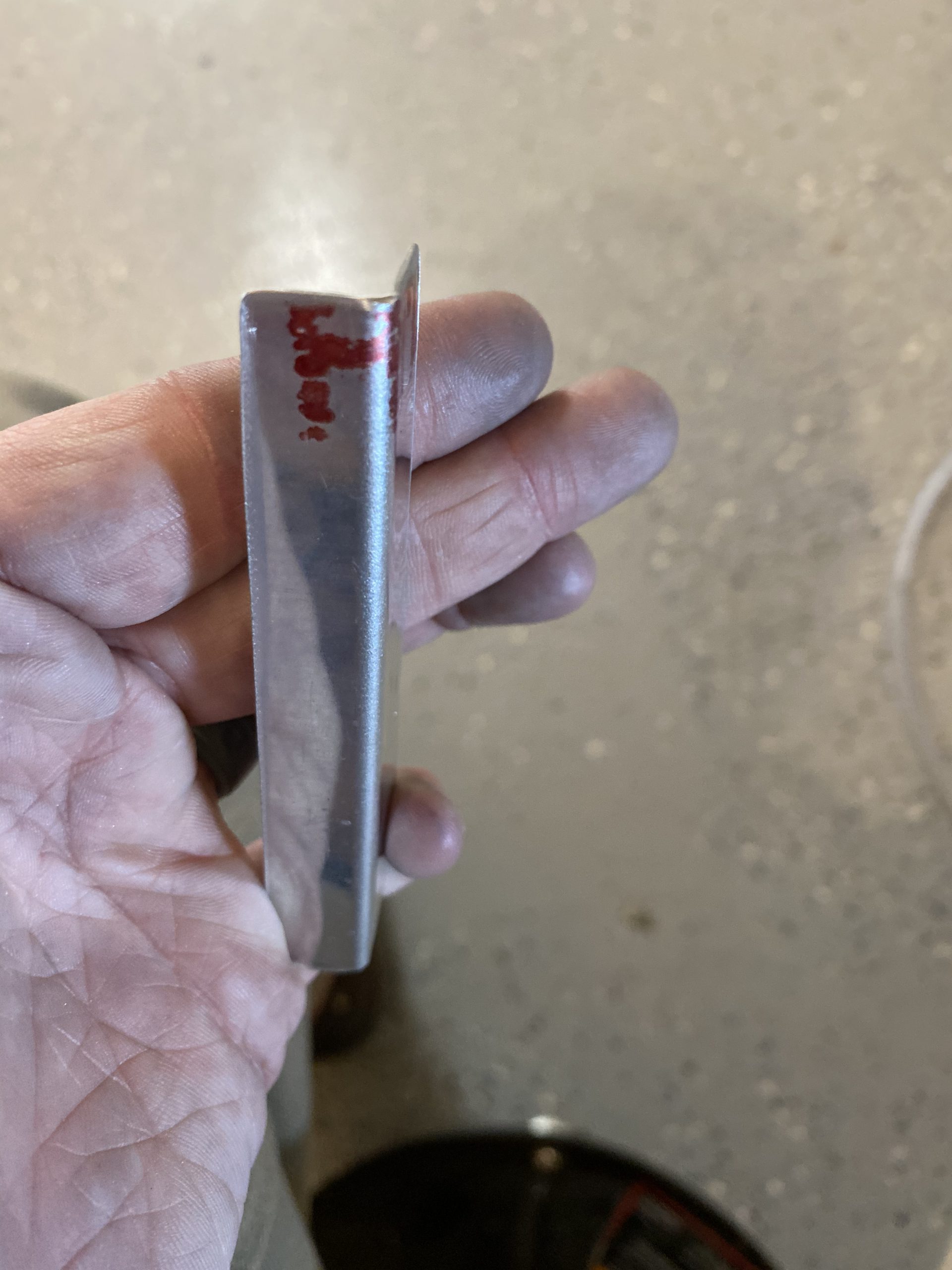
I made my brace by measuring and cutting a piece of the .032″ aluminum sheet and then bending it to make a 90 degree bracket in my bench vise. Then I clamped it in place against the rib, making sure it was sitting nice and flush with the reinforcement plate. This took a few times of bending, fitting, and bending, fitting again, before I got to what I liked.
I wanted to backdrill the bottom wing skin to the reinforcement plate before I drilled the bracket to make sure the plate was completely flush against the skin. So, I back drilled the wing skin, using the reinforcement plate as my guide, and clecoed the holes as soon as I was done to make sure it didn’t move. Then, I clamped the brace into place against the rib and lined it up with the reinforcement plate. At this point, I had all the holes back drilled into the SKIN from the plate. An important point, since once I had the brace clamped on, I needed to go to the other side of the wing, and backdrill the brace using the new holes in the skin and reinforcement plate as my guide.
After I had the brace drilled and clecoed to the reinforcement plate / skin assembly, I back drilled the plate to the wing rib. I decided to make these holes BETWEEN the holes I just drilled into the plate from the bracket. This would give me clearance to rivet the holes when I do the final assembly and riveting.
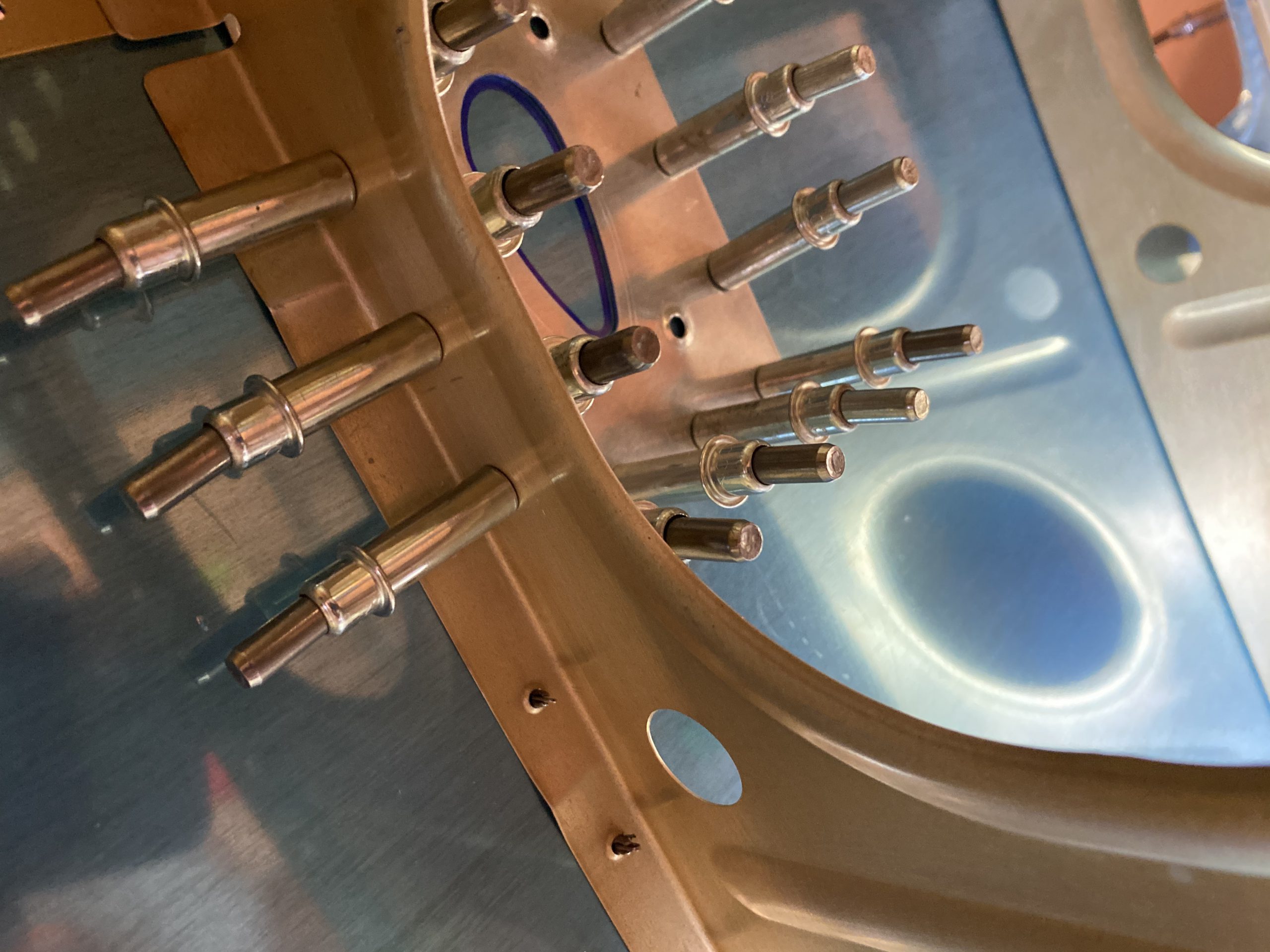
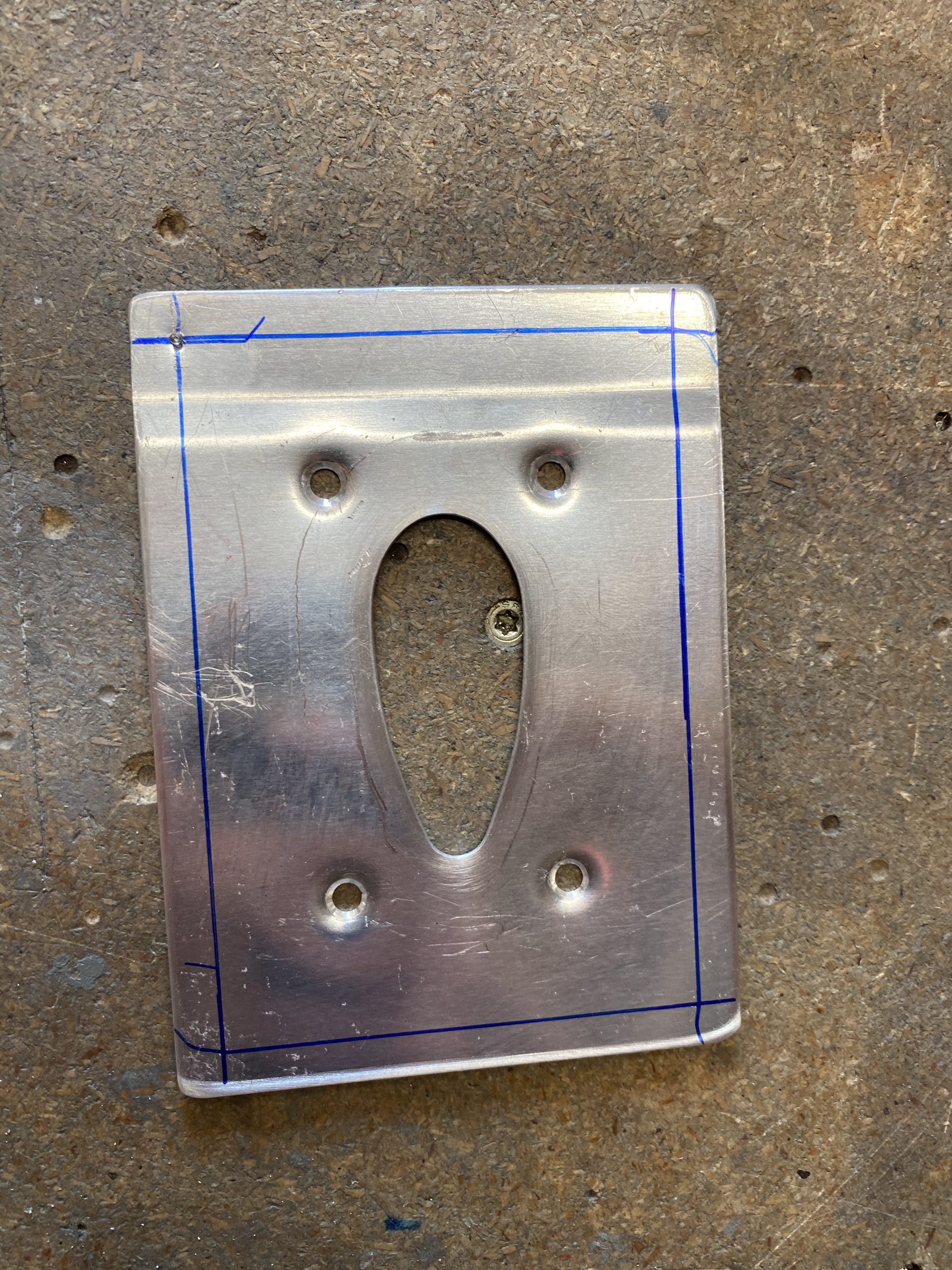
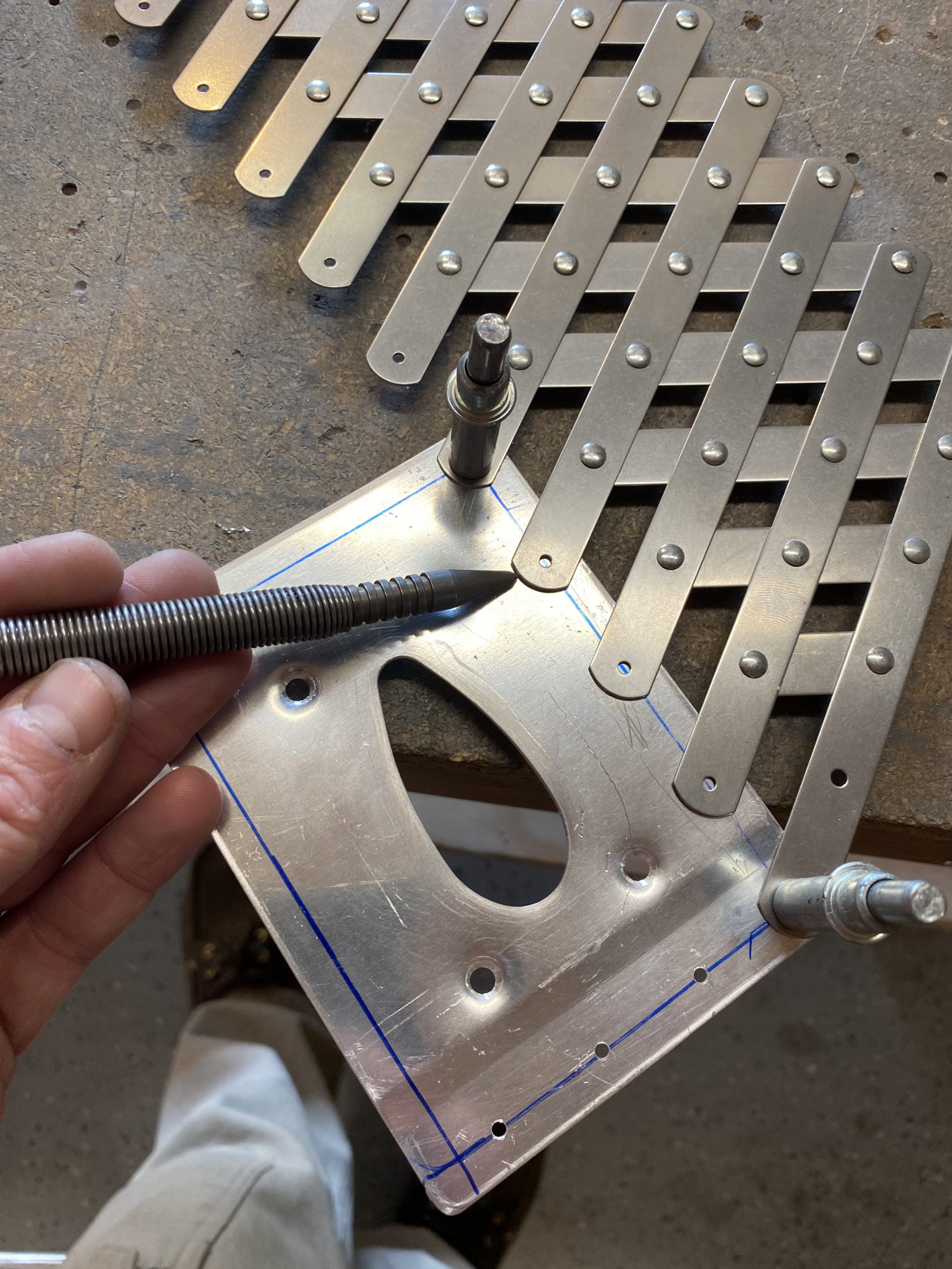
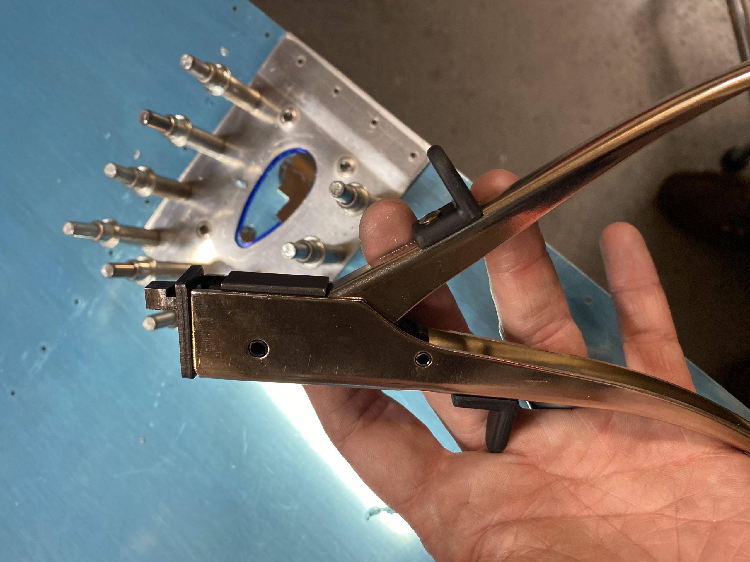
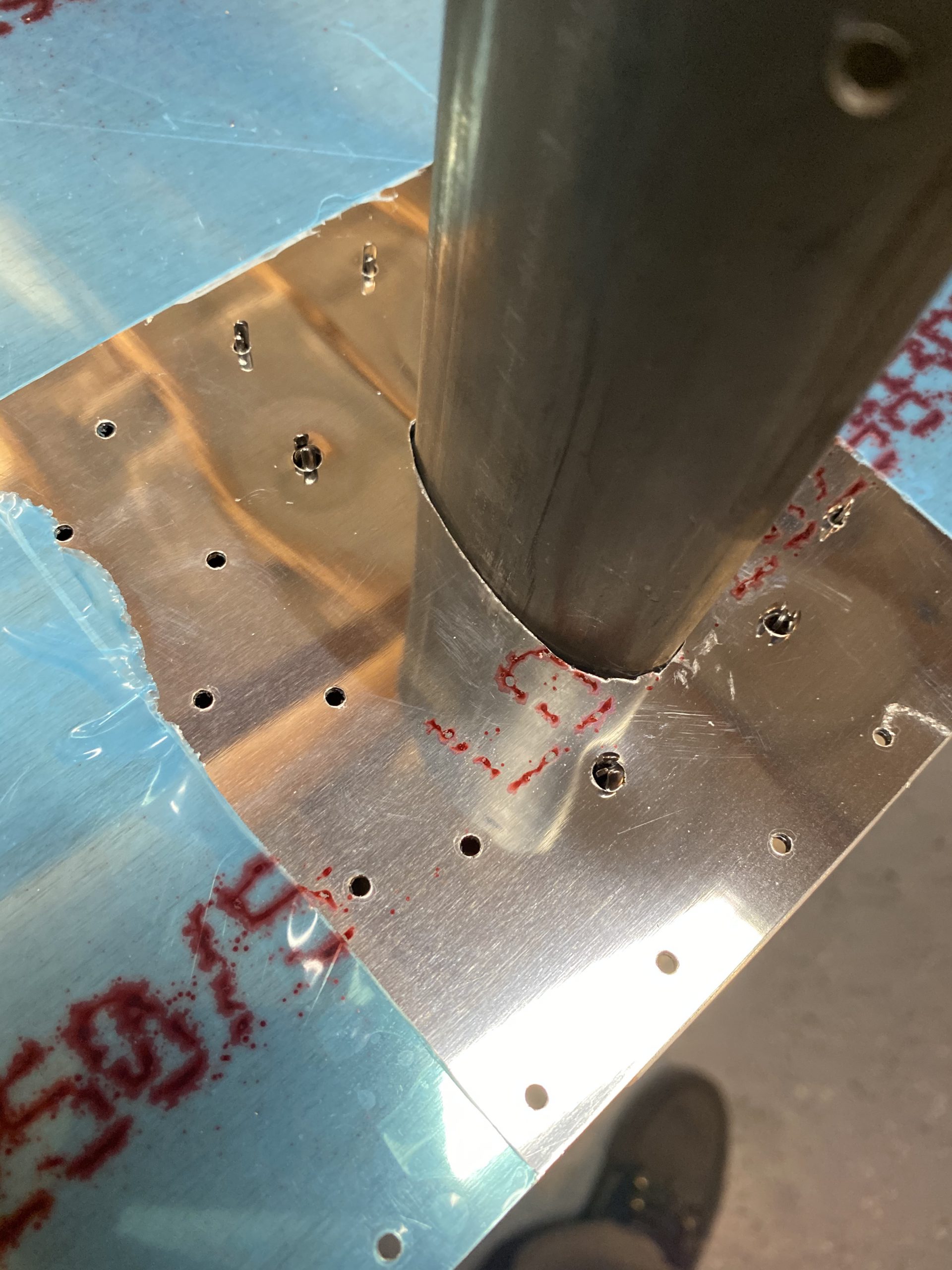
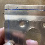
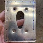
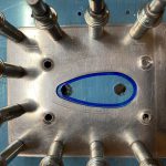
I’m committed at this point. The holes are drilled into the skin for the plate, now its time to cut out the hole for the pitot mast into the skin. I removed the skin and the reinforcement plate from the wing, and set it up on my bench. To cut out the streamlined shape of the mast, I decided to drill some holes, and use a nibbling tool. I picked out a drill bit that gave me a decent shape for the small end of the mast hole, I don’t recall the size, I was eyeballing what would get me close. I think it was a 3/8 bit? I used the same bit to drill the hole in the large end, and opened the hole up using a uni-bit.
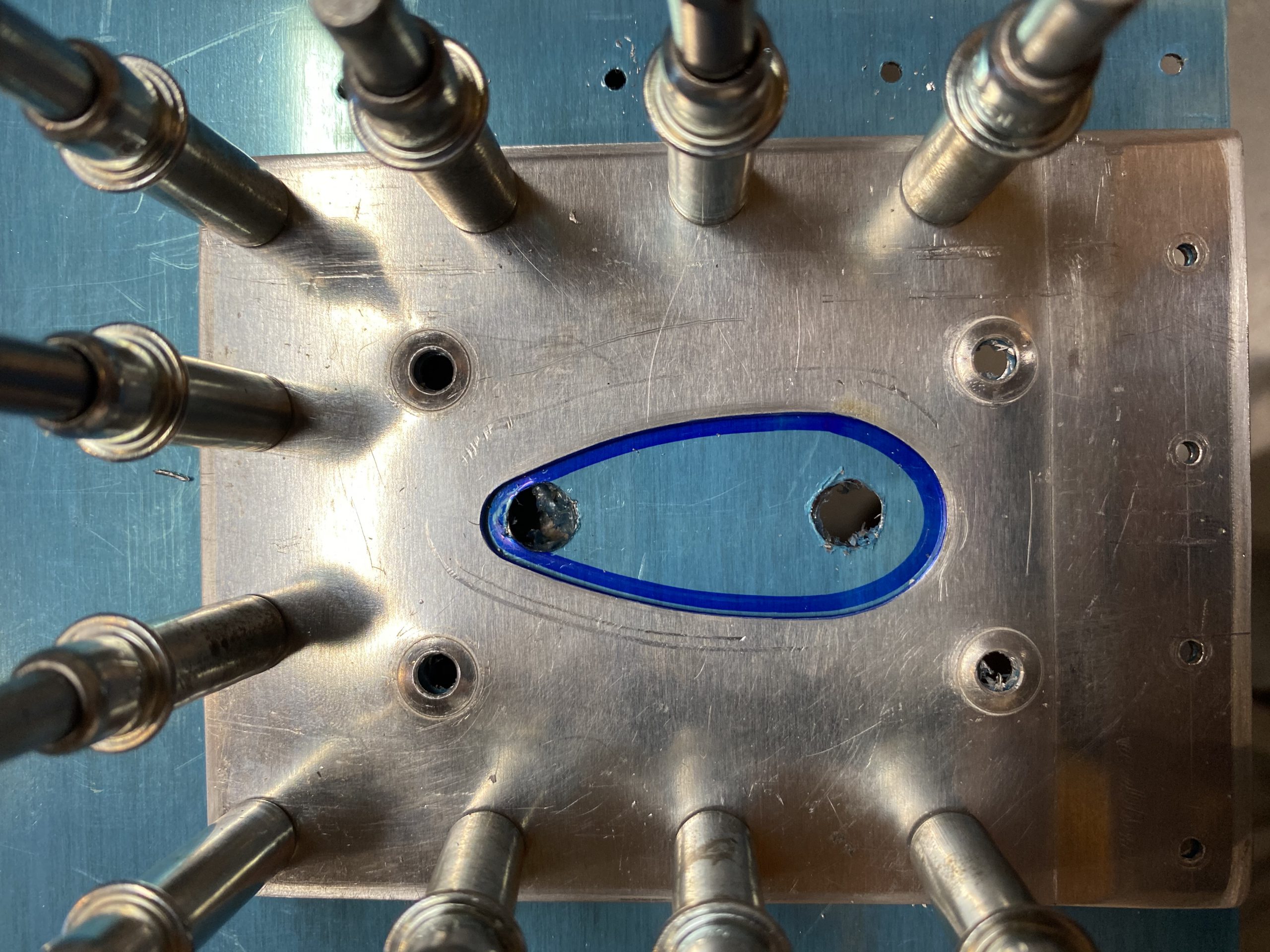
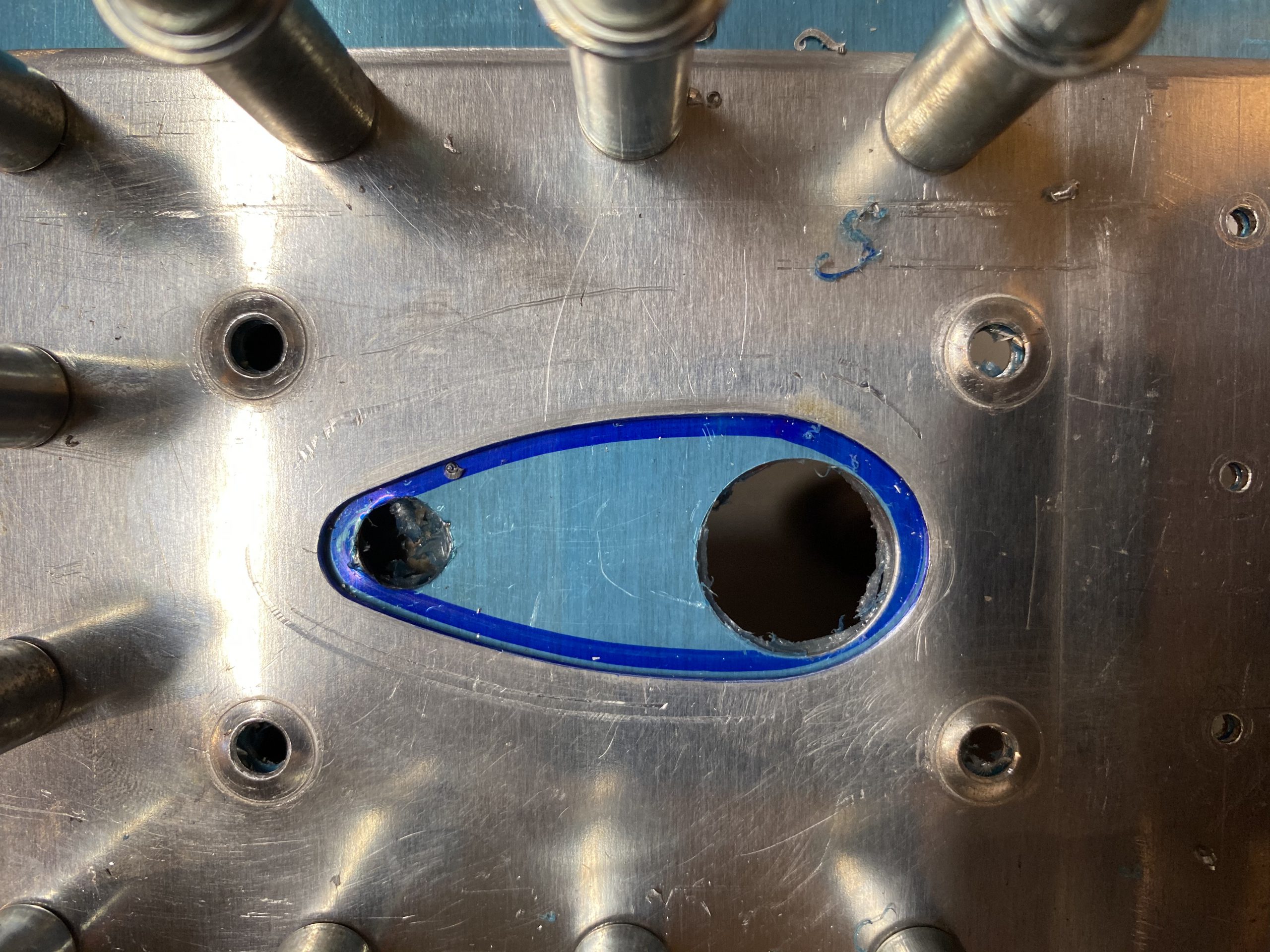
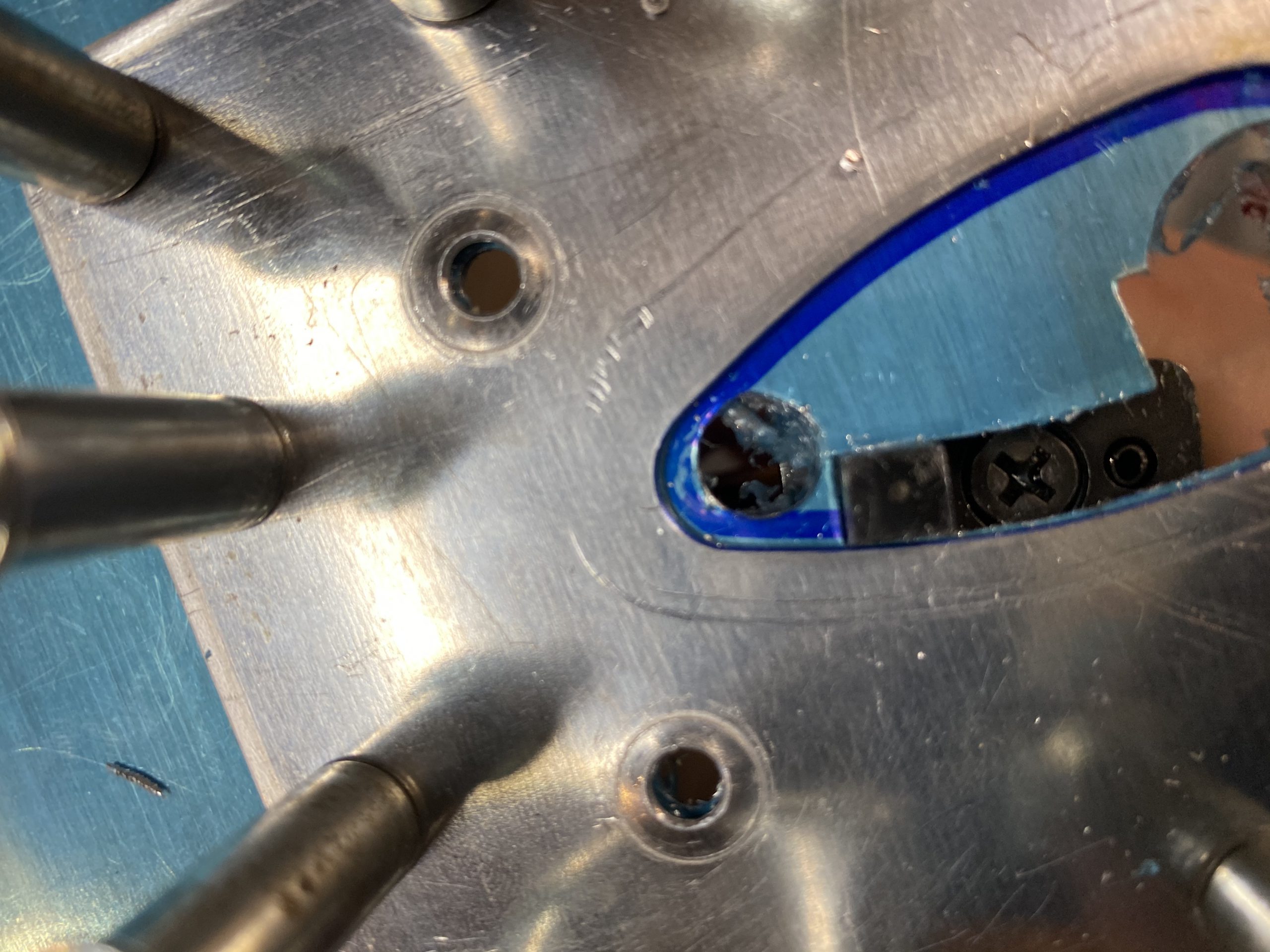
Notice I did leave the reinforcement plate clecoed on, and marked the hole with a thick sharpie. I am using this as my template for the skin cutout.. The uni-bit was able to get really close to the blue sharpie. Next up I grabbed the new nibbling tool and slowly and gently nibbled out along the blue line. I found that I was able to place the nibbling bit up from the bottom of the skin, and use the shoulder created by the reinforcement plate as a guide for the nibbler, and this worked out very good. Its a great tool for this work, and it costs like 14 bucks!
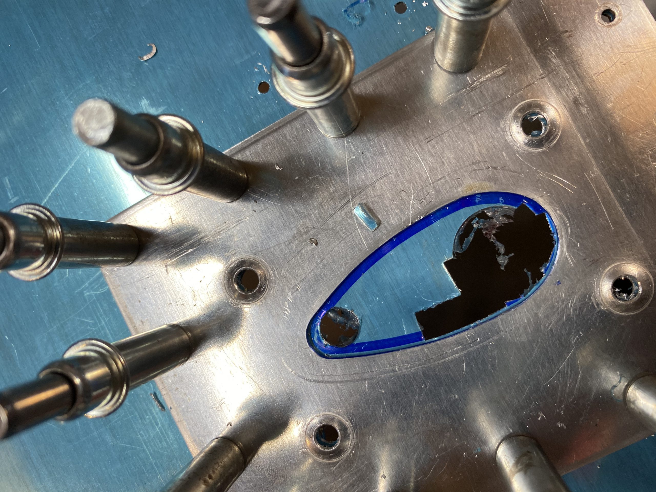
I worked very slowly and took very small nibbles to make sure I didn’t go to far. I highly recommend using this tool for doing this sort of complex hole cutting. Here is a photo showing where I am sticking the nibbler UP from the bottom side of the skin and using the cutting head to rest on the reinforcement plate to use as a guide. Eventually I had a very nice, rough cut that required very little filing and finish work
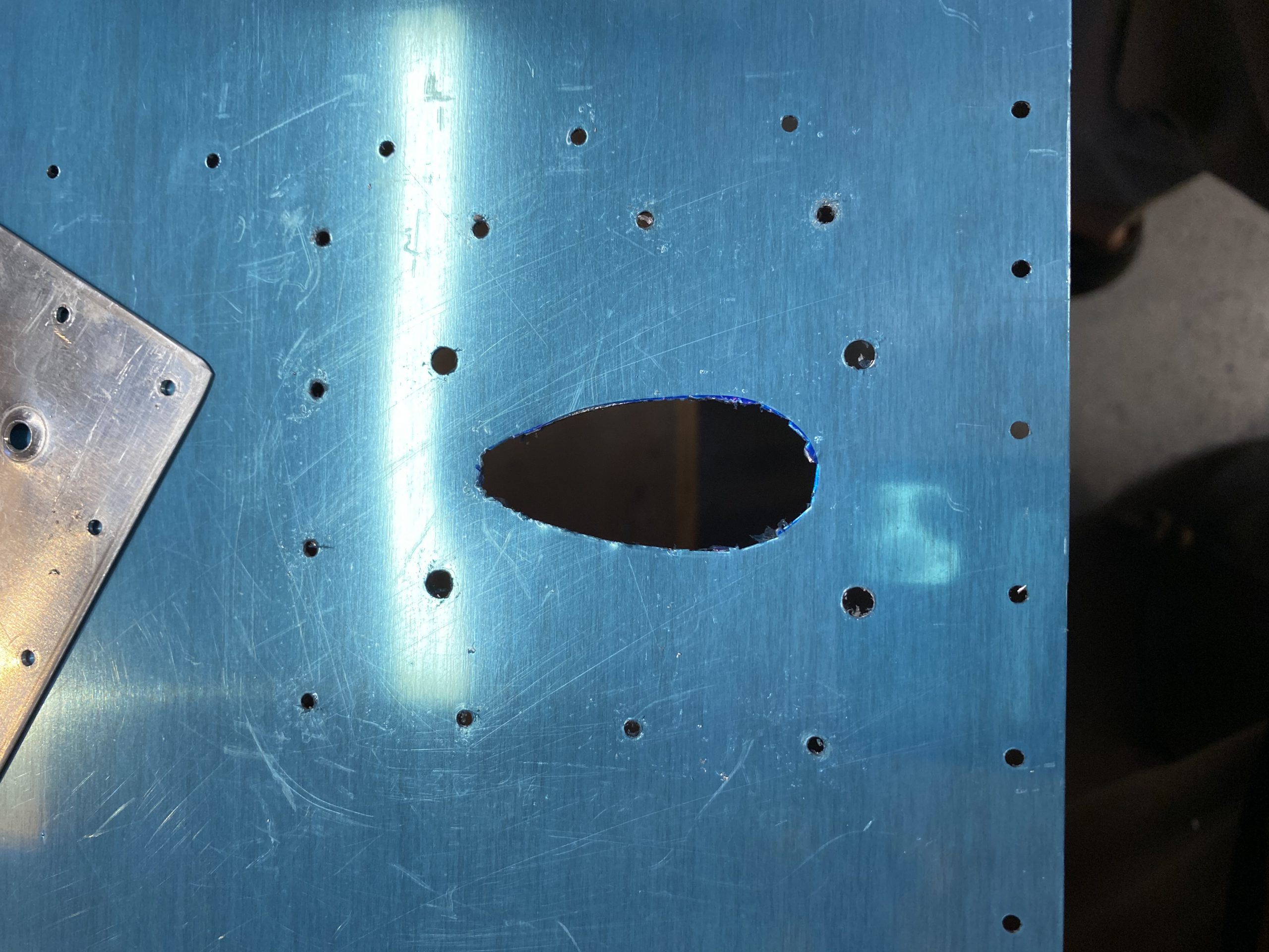
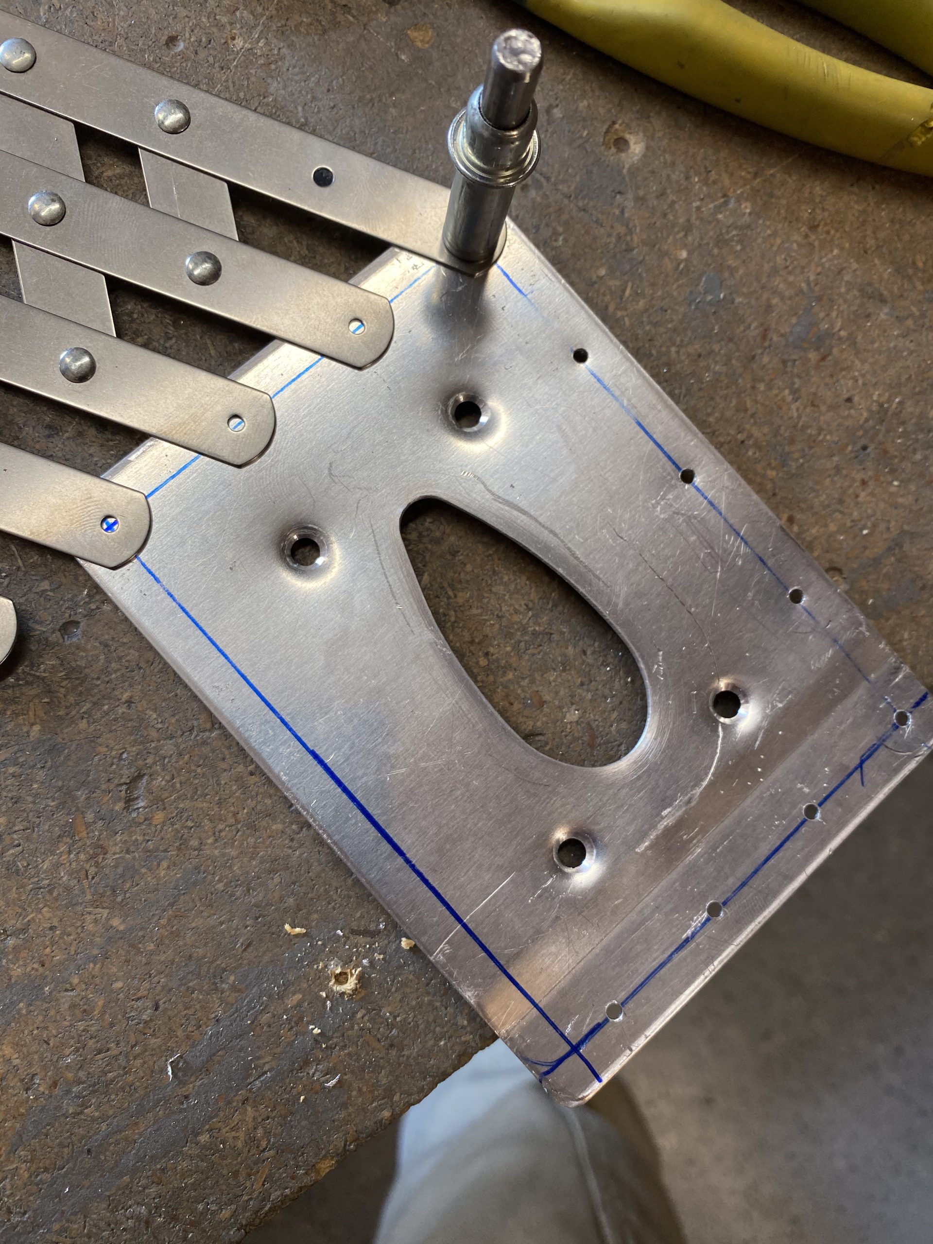
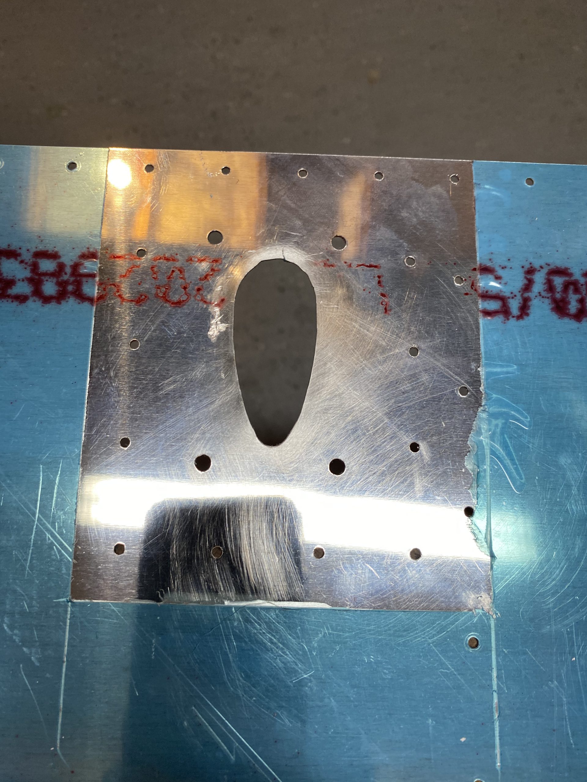
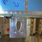
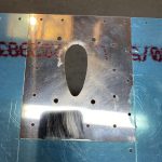
Then, I removed the reinforcement plate, and used a combination of files to smooth out the edges of this new hole, and then widen it ever so slightly to fit the pitot mast. Very similar to how I had to file down the plates to fit the mast at the first of this build session. The time lapse show this work much better. Eventually I ended up with a very close fitting hole that will look great for the pitot mount to stick through on the skin! Here is how it looks mid-process:
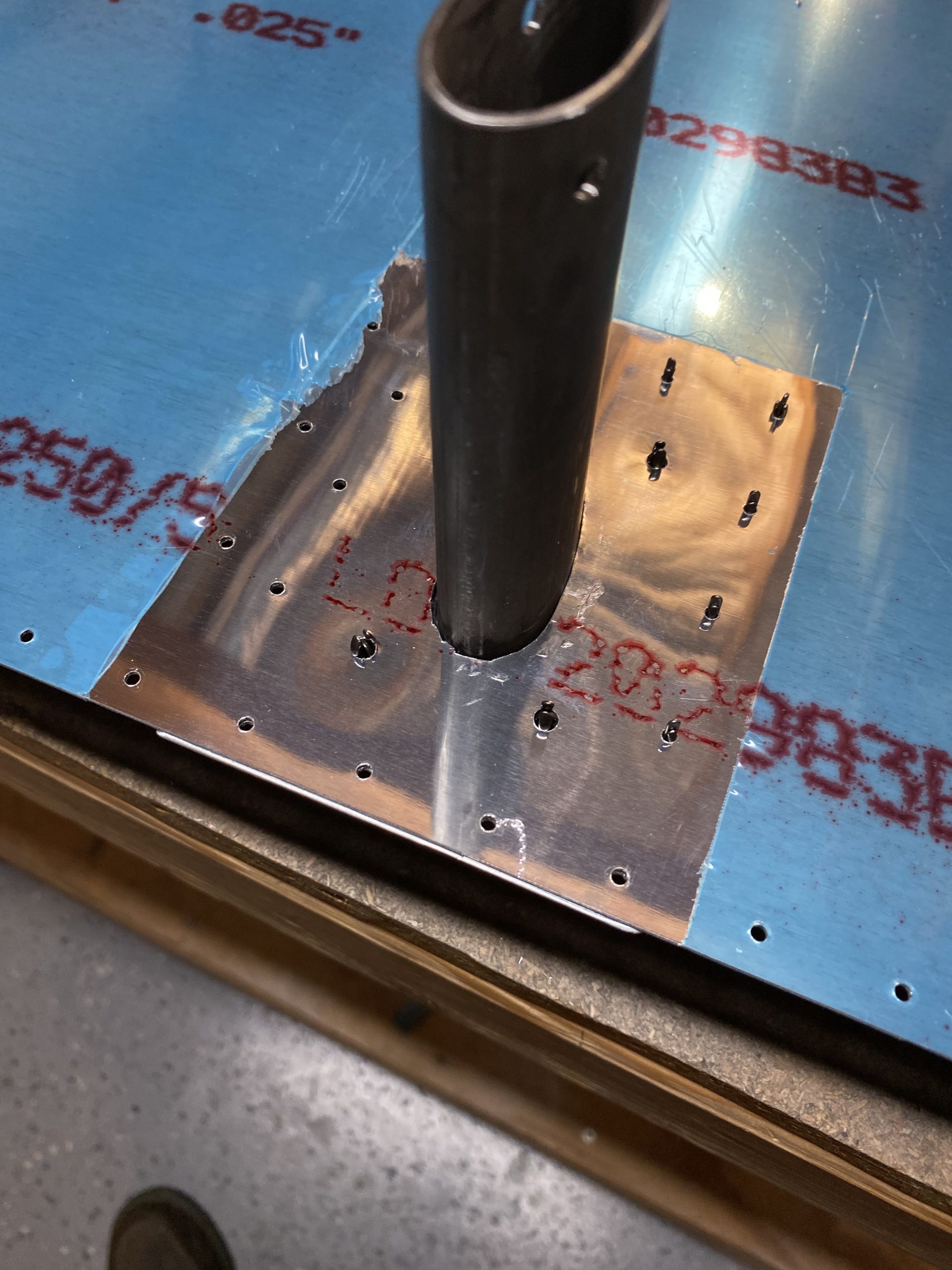
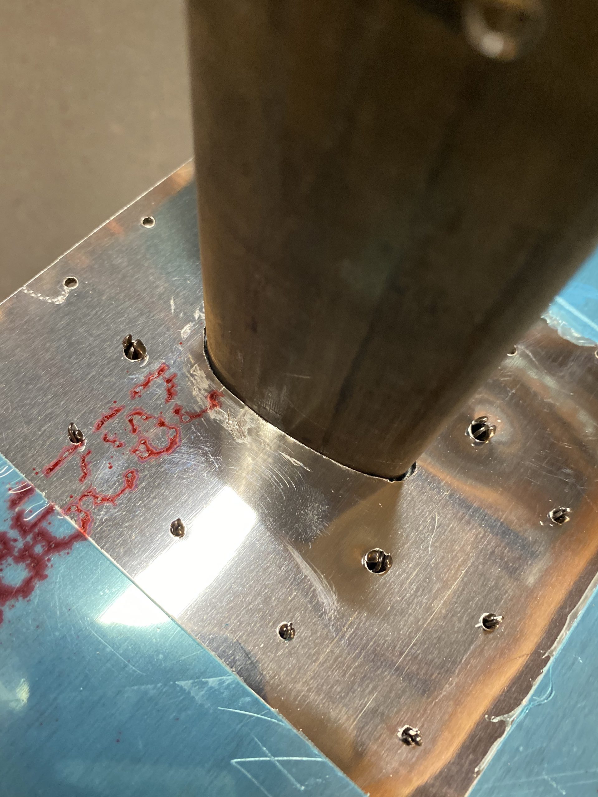
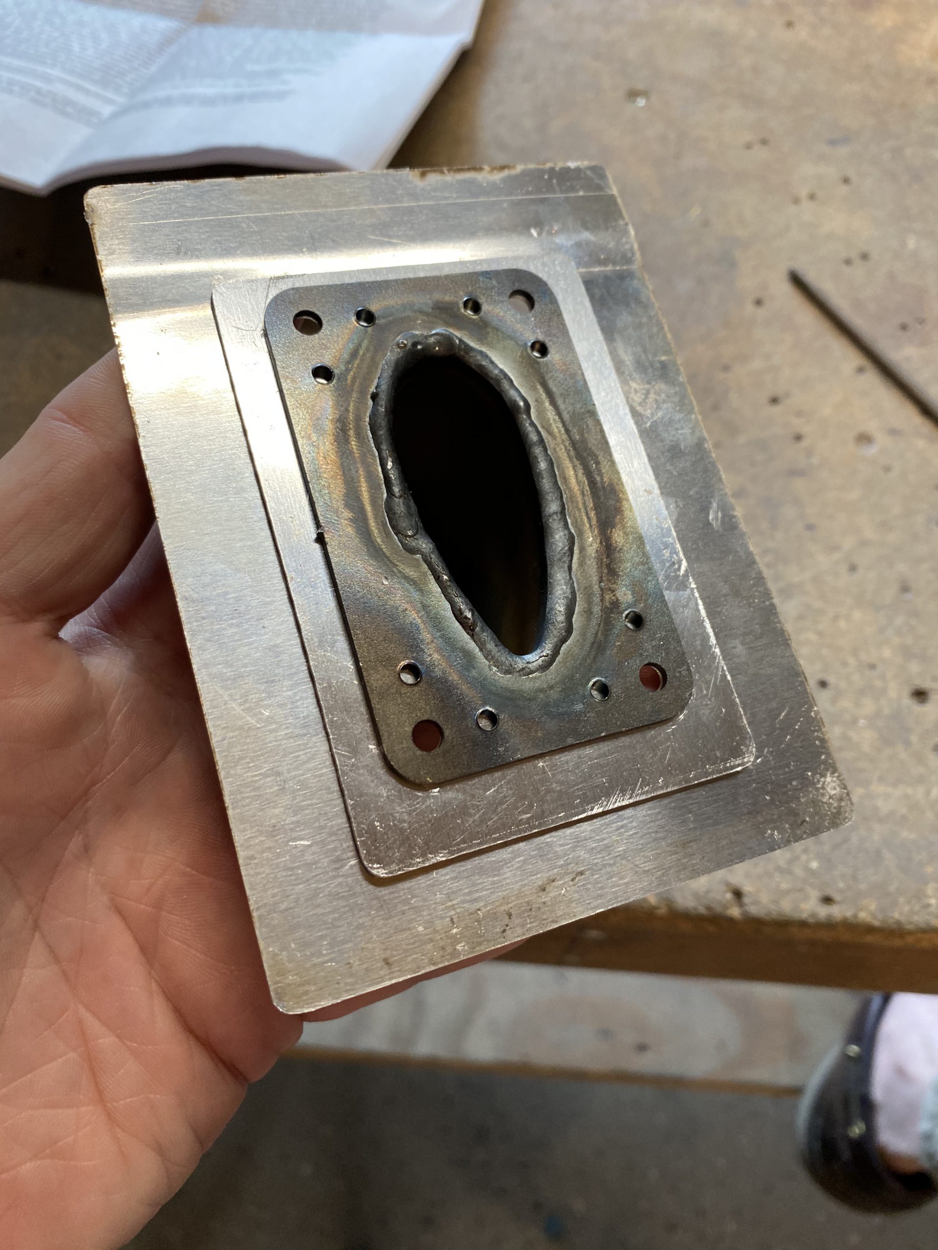
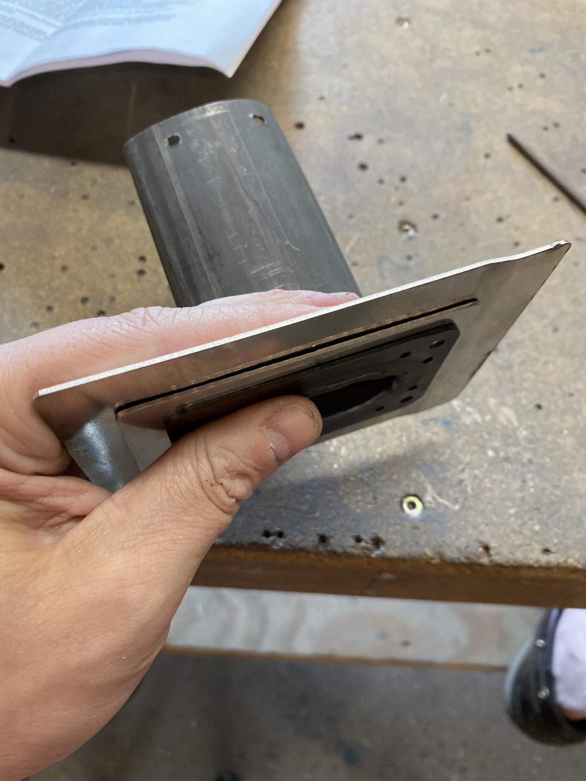
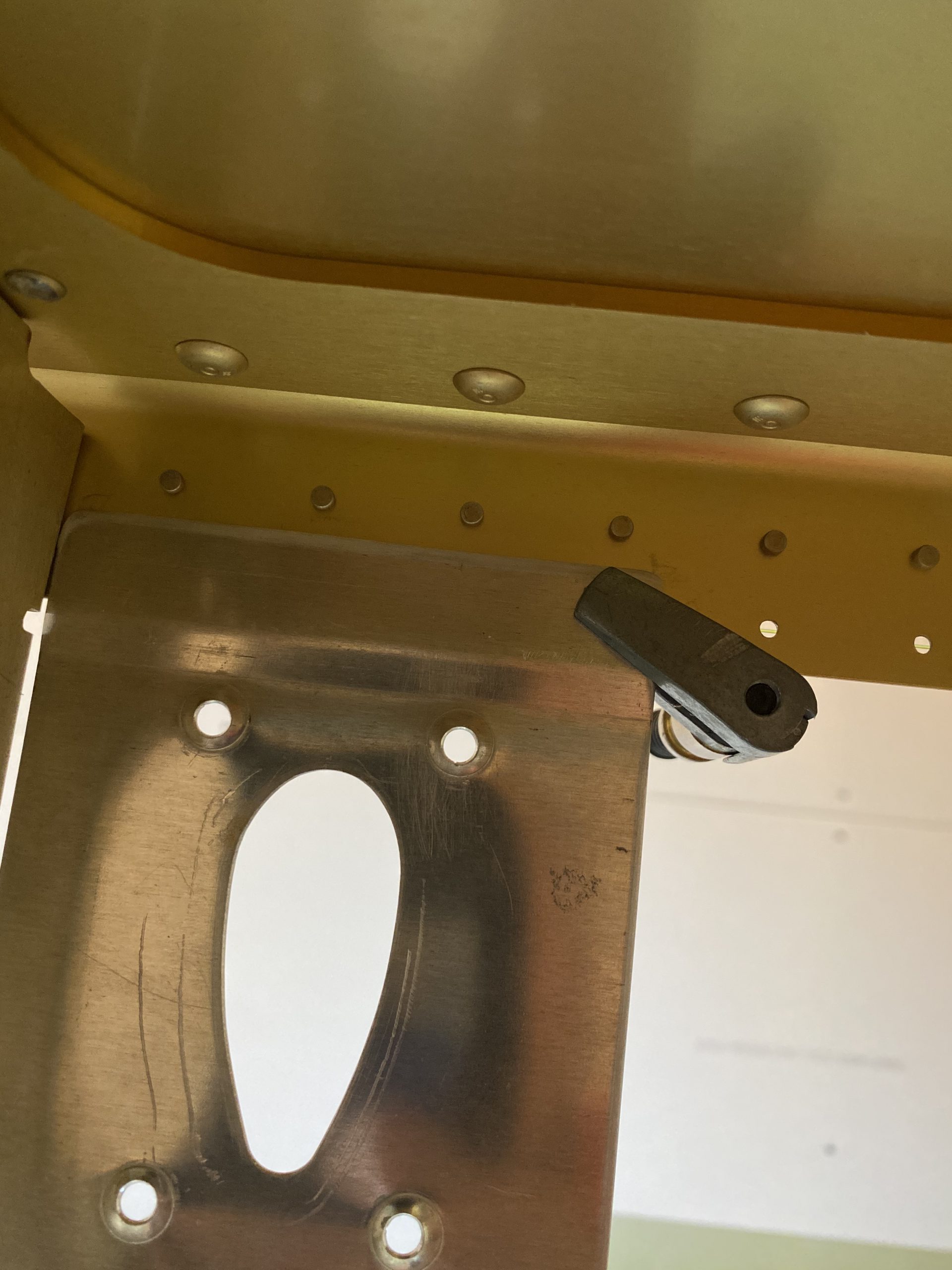
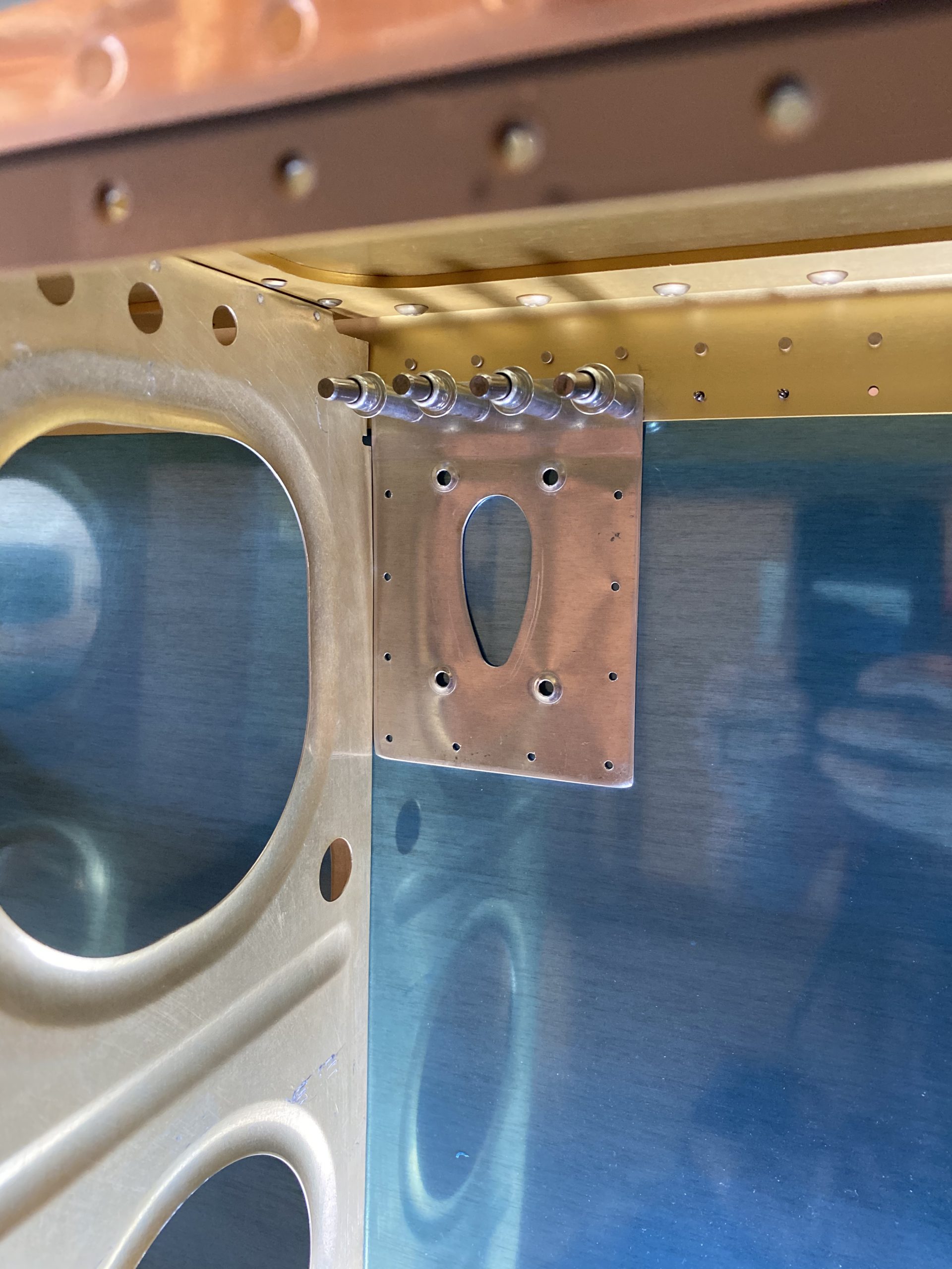
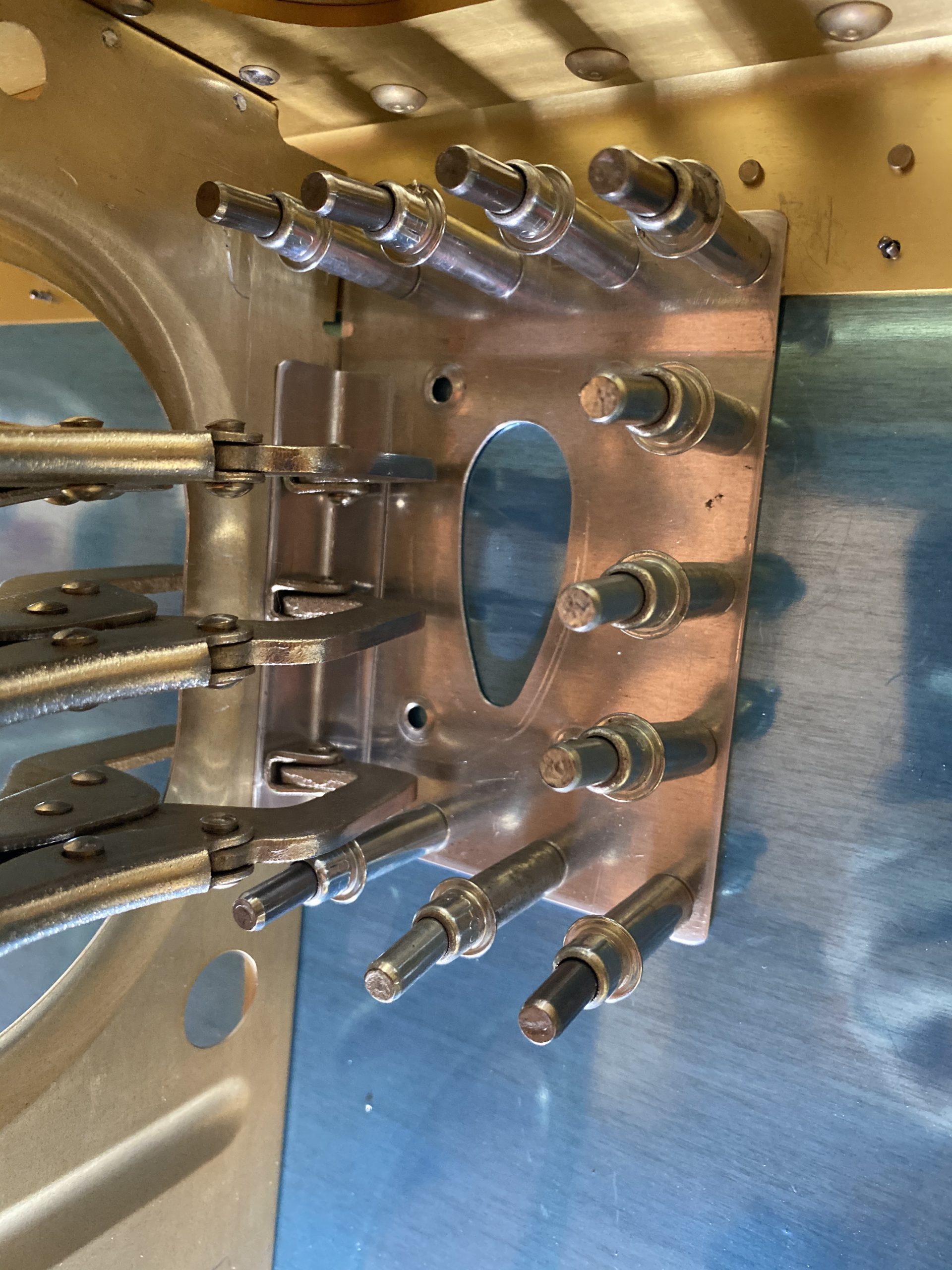
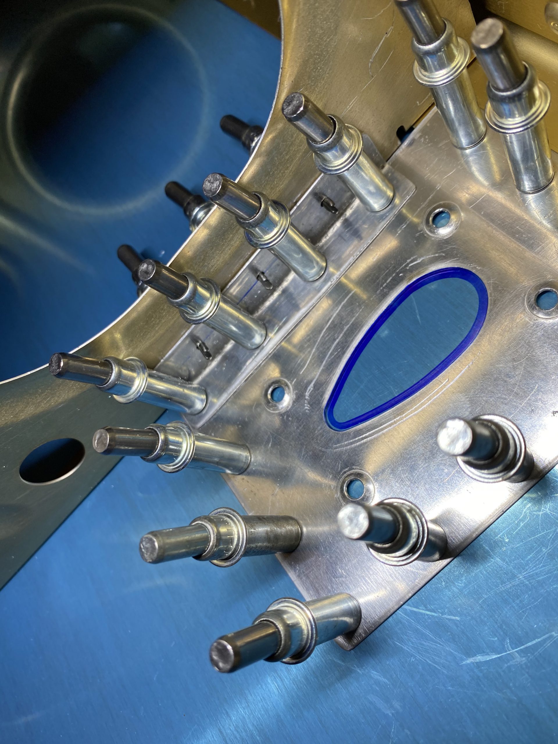
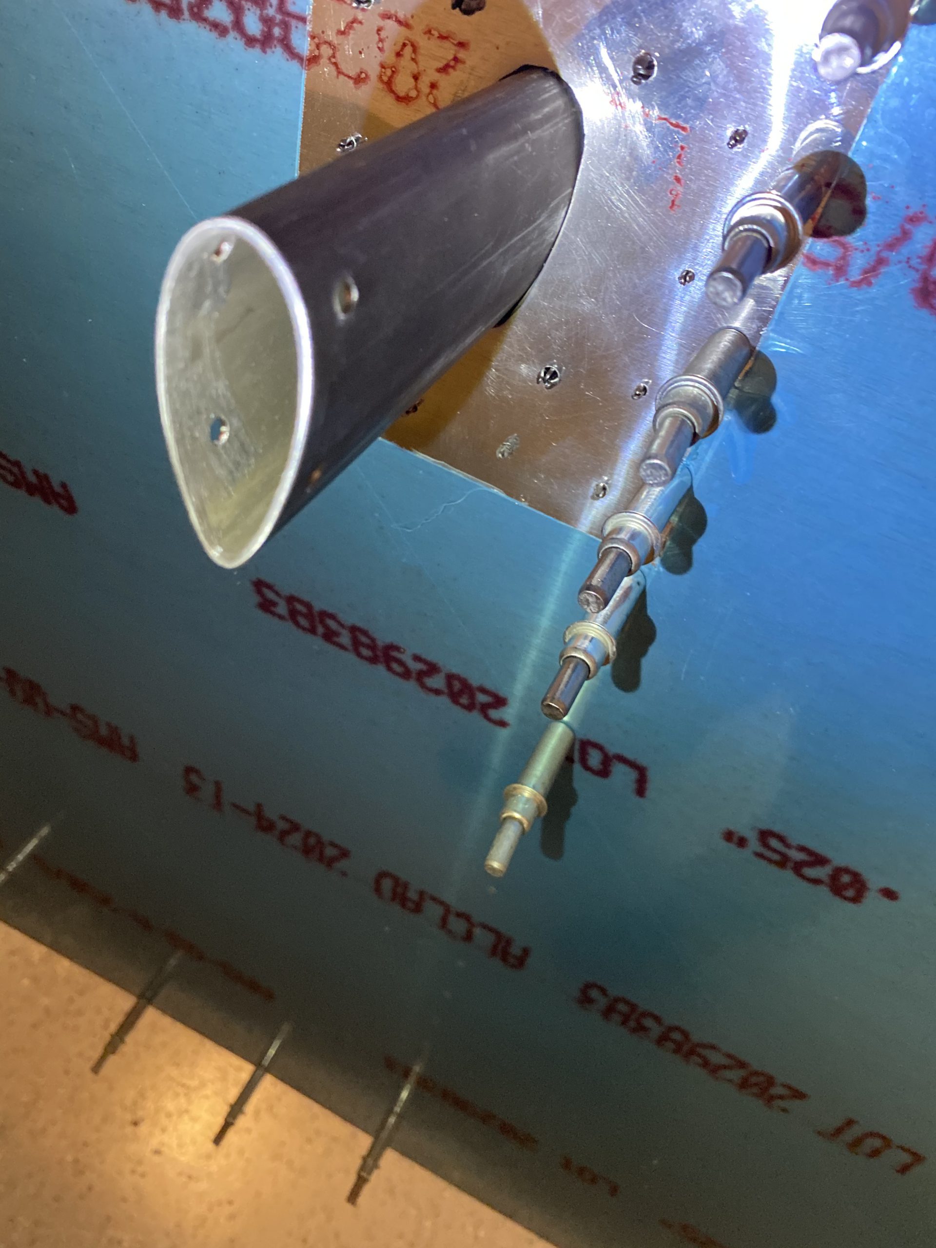
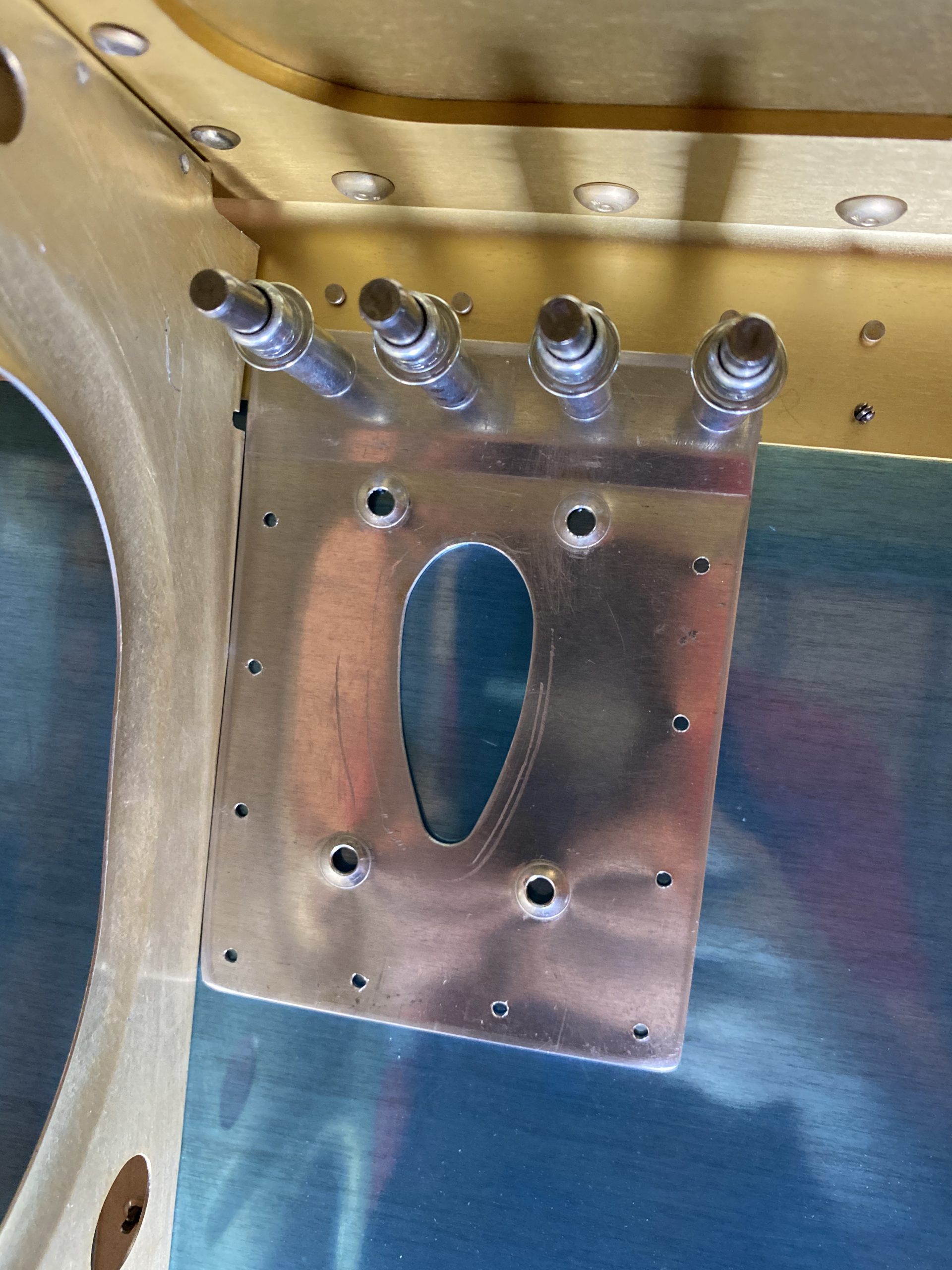
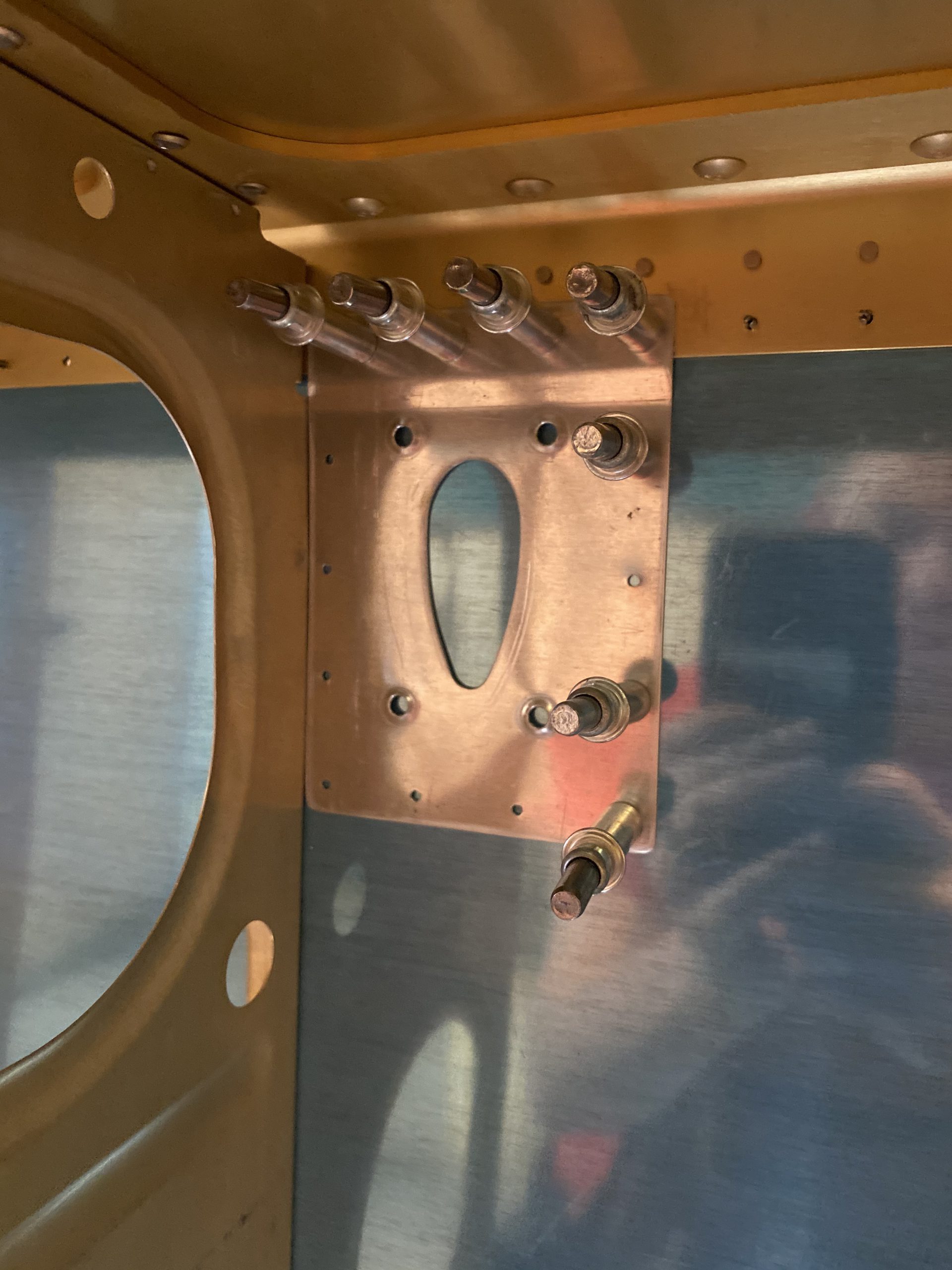
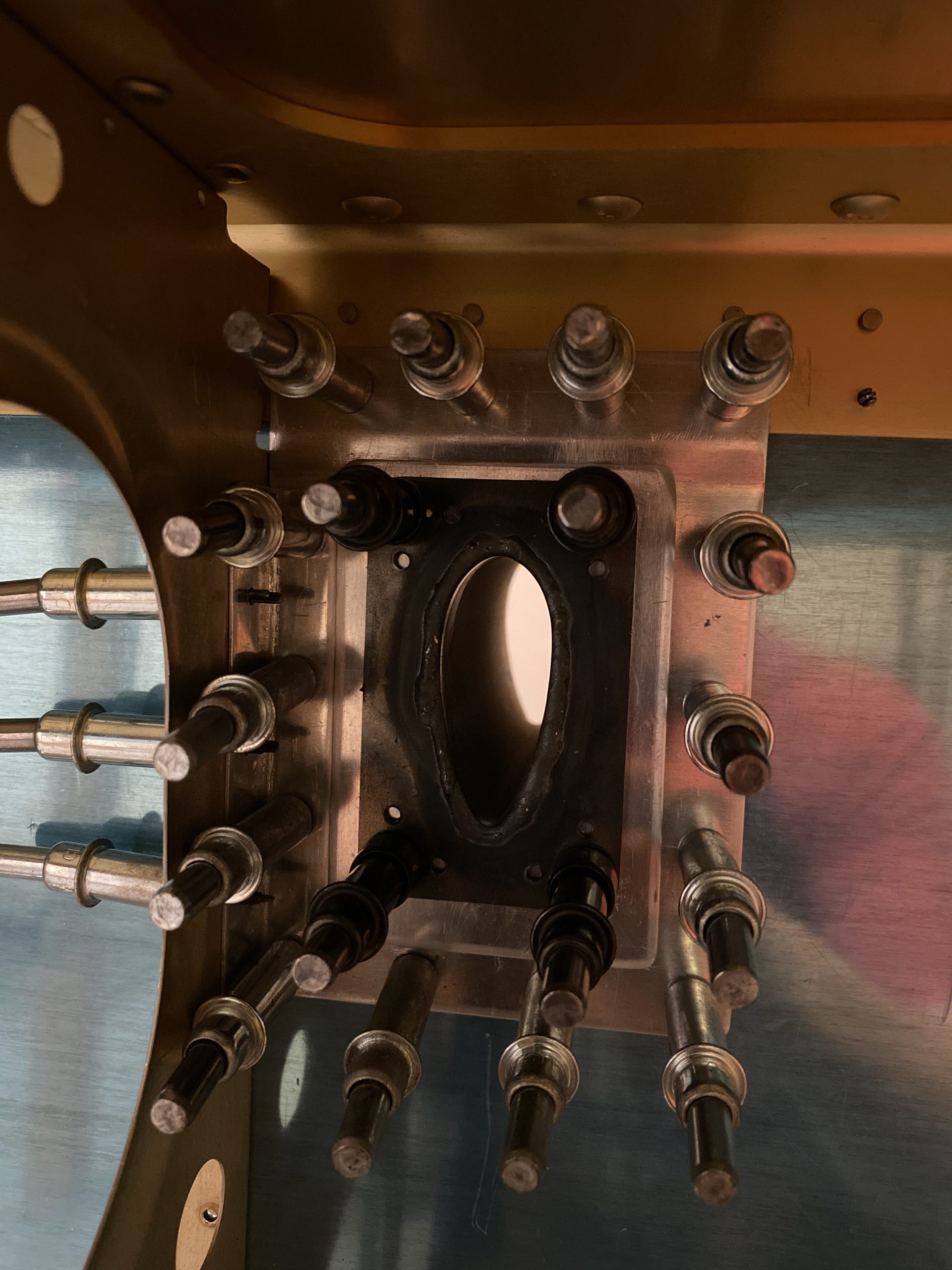
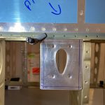
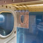
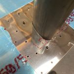
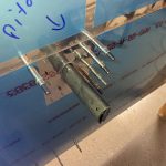
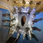
To make sure everything is correct before I do the last bit of finish work, I clecoed everything back onto the wing skeleton and fit the pitot mast in its new home. It turned out really slick! I am really happy with this.
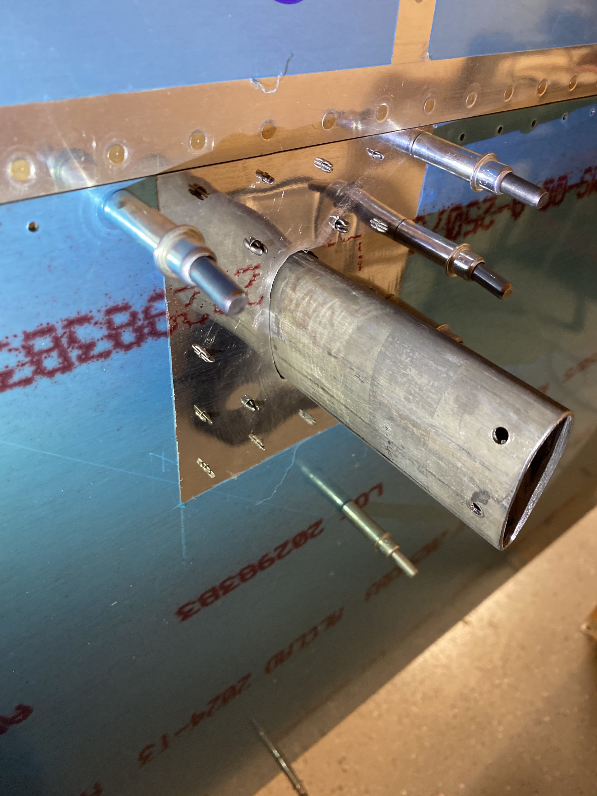
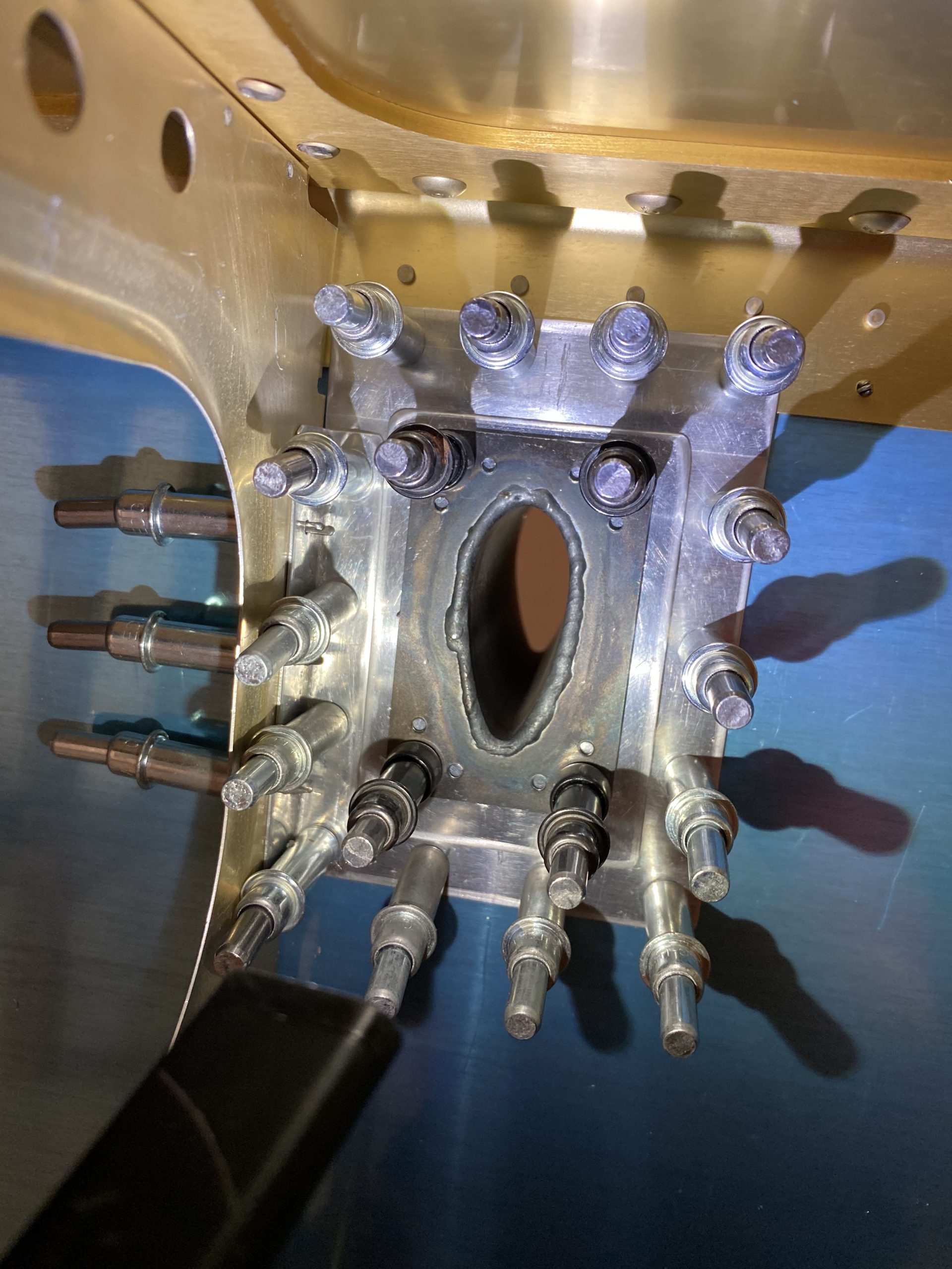
Here is how it looks on the inside of the wing. This is going to be very easy to service if I ever need to. It’s also very strong with all those plates and braces securing it to the skeleton of the wing, its not just dangling and flopping around from being attached to the skin or an access plate. This is solid.
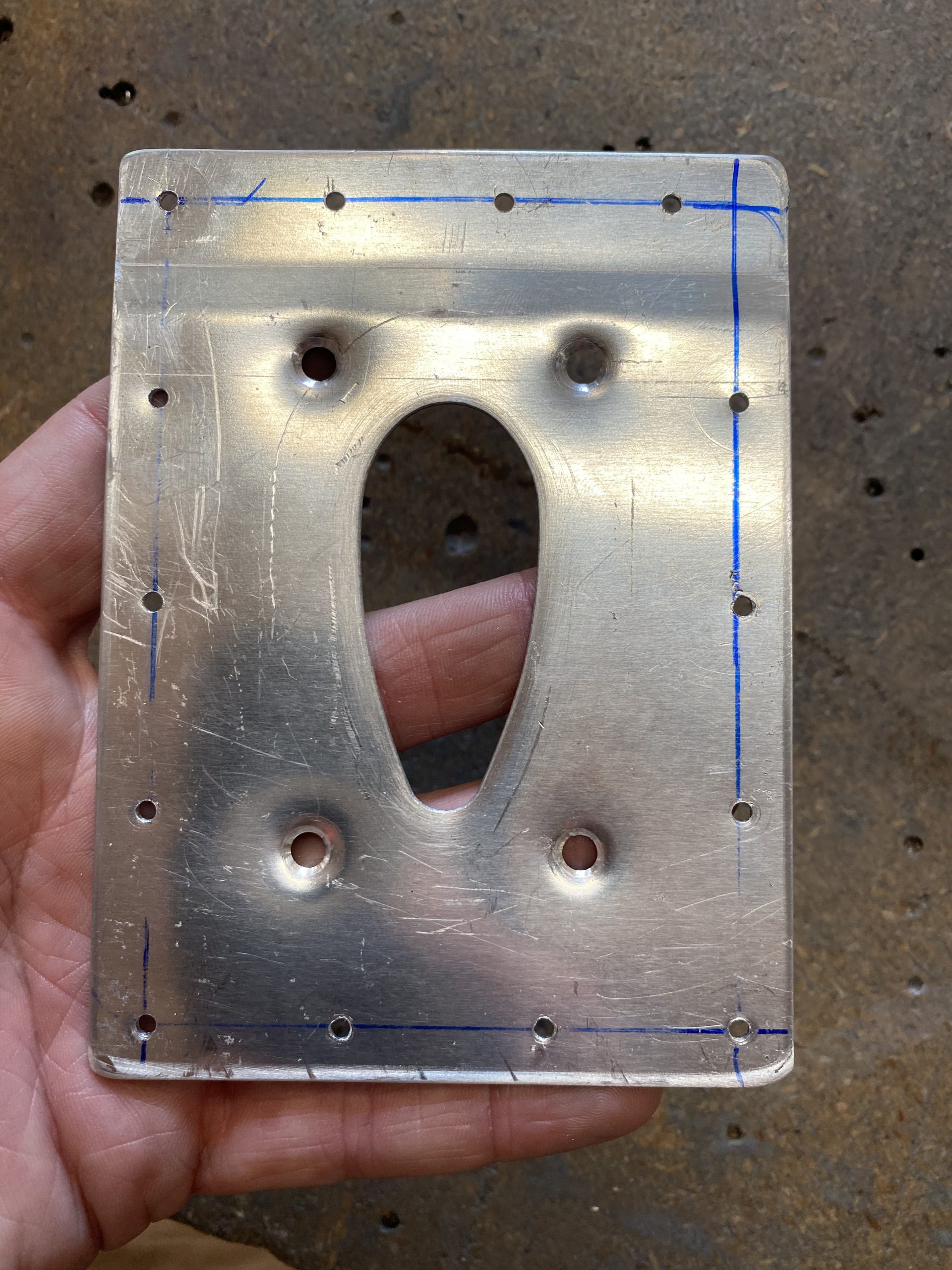
Then, I dissambled everything, and cleaned up all the holes with some files, deburring tools and scotchbrite. I made sure to get the hole I nibbled in the skin for the mast nice and smooth with no sharp corners to start a crack. These parts are now ready for assembly. I am going to alodine all the plates and braces for the pitot, and then I am considering sending off the pitot mast itself to be chromed at a local old-school hot rod shop thats been doing chrome since the 50’s. I think a chrome pitot mount will look very nice, and be very durable. Maybe it won’t cost much? I’ll report on it later.
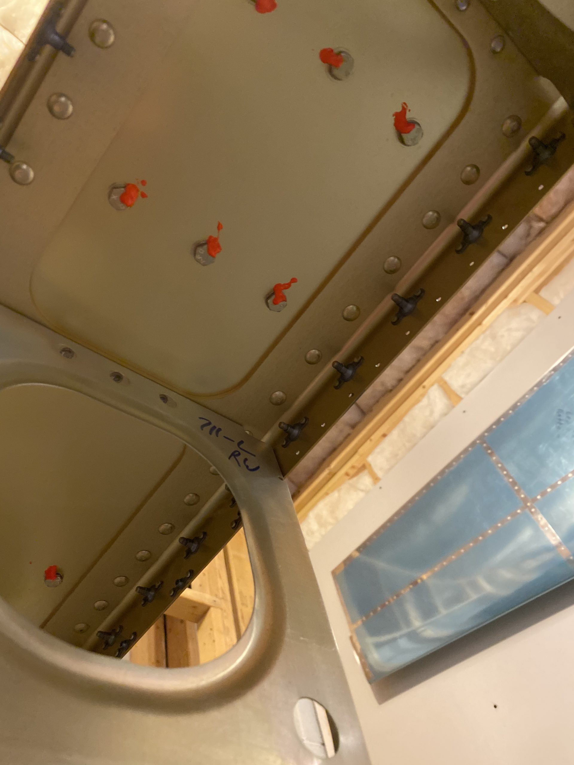
I had a few loose ends to finish up tonight. My Tekton 1/4″ torque wrench delivered today and MAN is this thing nice! I am now a huge Tekton fan. This wrench was only about $43 bucks from Amazon: https://amzn.to/33n1Ce2 I love it. I needed to torque down the fuel tank Z-bracket bolts on the main spar web. I decided to go with 40 inch/lbs, as the spec for this is 28 inch/lbs plus the drag of the nutplate. I measured about 14 inch/lbs of drag so I went with 40 inch/lbs and I think thats good. The Tekton has a nice “thunk” when it hits the torque spec. Once I had all the bolts torqued, I marked them with some orange TorqueSeal. I did this for both the left and right wings. The tanks are now mounted!!
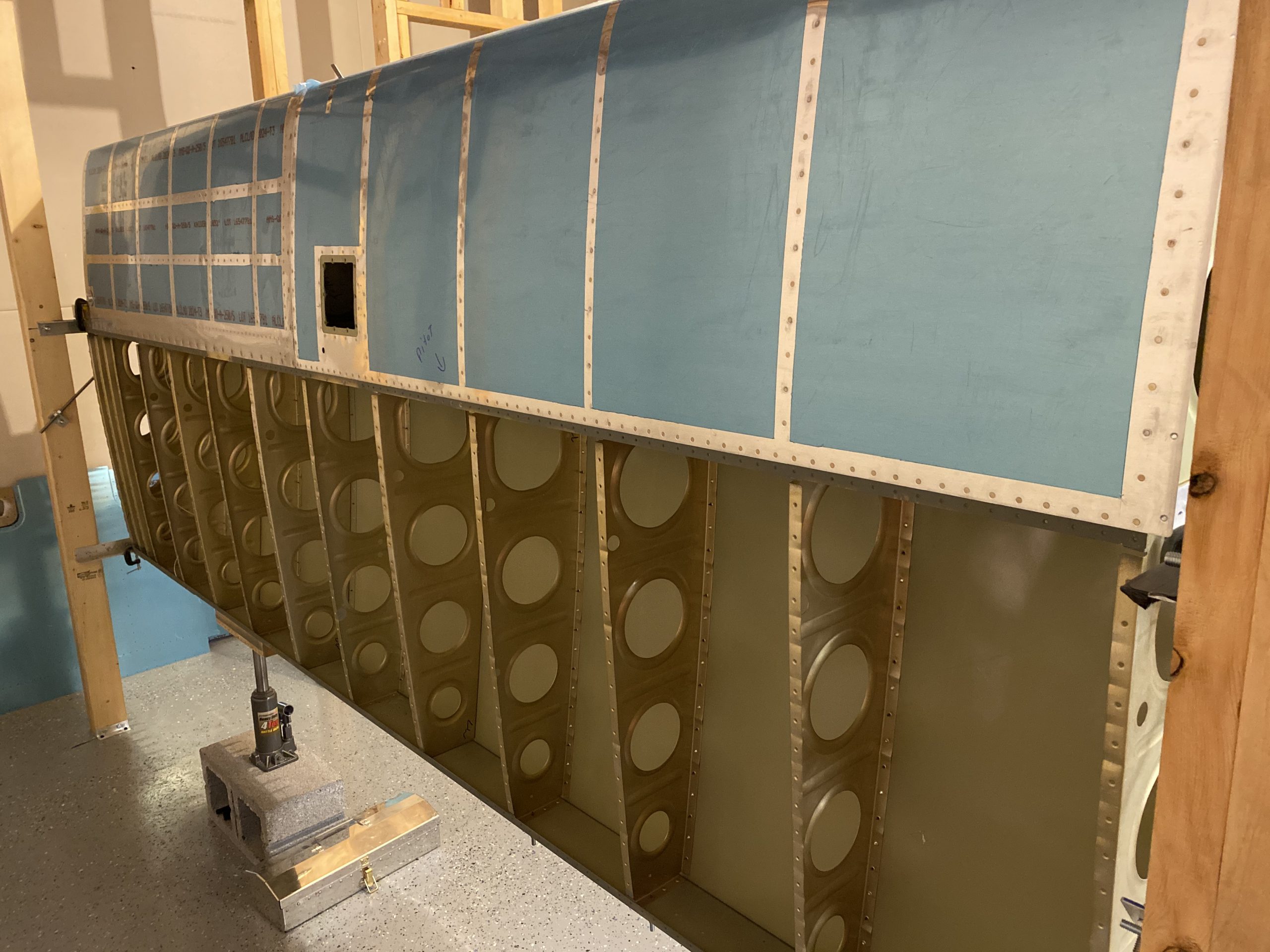
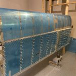
Lastly, I decided to go ahead and cleco the left wing outboard top skin to the skeleton, as the left wing is now 100% ready to have its top skins riveted on. It feels amazing! I am planning on getting Tammy to help me do this, maybe the right wing too, later on this week. It’s looking like a wing now!
That’s it for today. This was a LONG work session, and I got a ton completed. I’m stoked to have my pitot mount done, and I’m looking forward to all the rest of the work now. I still need to get the right wing skin dimpled, and clecoed on, so that maybe work for tomorrow. Then I’ll alodine the pitot mount parts, and send the mast off for chrome plating. I think I will go ahead and get the bottom skins primed now as well. They won’t get riveted until WAY later right before mounting on the fuselage, as I still haven’t decided which autopilot I’m going with, or lighting.
Google Photos Link: https://photos.app.goo.gl/K5VLPd1bZoX4G2Uq9
-
 IMG_2558
 -
IMG_2559
-
 IMG_2560
 -
IMG_2561
-
IMG_2562
-
IMG_2563
-
IMG_2564
-
 IMG_2565
 -
IMG_2566
-
IMG_2567
-
 IMG_2568
 -
 IMG_2569
 -
 IMG_2570
 -
IMG_2571
-
IMG_2572
-
IMG_2573
-
IMG_2574
-
 IMG_2575
 -
 IMG_2576
 -
IMG_2577
-
IMG_2578
-
IMG_2579
-
 IMG_2580
 -
IMG_2581
-
 IMG_2582
 -
IMG_2583
-
IMG_2584
-
 IMG_2585
 -
IMG_2586
-
IMG_2587
-
IMG_2588
-
IMG_2589
-
IMG_2590
-
IMG_2591
-
IMG_2592
-
IMG_2593
-
IMG_2594
-
IMG_2595
-
 IMG_2596
 -
IMG_2597
-
IMG_2598
-
 IMG_2599
 -
IMG_2600
-
IMG_2601
-
IMG_2602
-
IMG_2603
-
 IMG_2604
 -
IMG_2605
-
IMG_2606
-
IMG_2607
-
 IMG_2608


Hours Worked: 5.0