


After a short break, I came back down to the shop to get the alignment jig made. I’ve ready a few ways of doing this, but honestly, Vans has the most simple way of doing it and its worked for countless other builders, so I decided to stick with convention on this one.
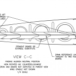
Looking at the drawings, Vans has us make a simple alignment jig using a straight board or other straight material. Then we use the tooling holes in the outboard rib, drill matching holes into this board, and draw two lines tangent to the holes to use to lineup the trailing edge of the aileron. Super simple and effective. Here’s the section of the drawing to give a better idea:

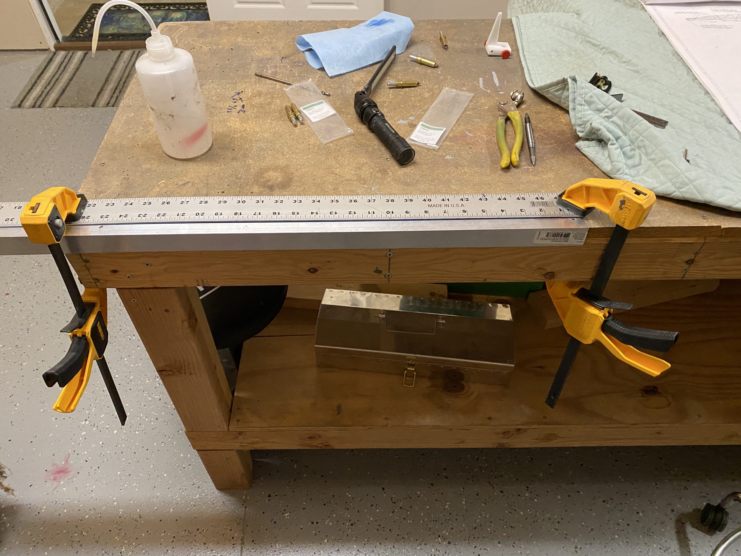
Luckily, I had a spare piece of 1.25″ x 1.25″ angle aluminum that would do the trick nicely. This angle even had a little divot cut right down the center of one of the legs! I was skeptical at first, but after measuring it all the way down, it was truly right down the center. Must have been from the manufacturing process or something, but it worked a treat. I started out by drilling a #12 hole near the end of the angle, so I could fit an AN3 bolt through the angle and bolt it to the rib, as called out above. I used that center line divot as a guide.
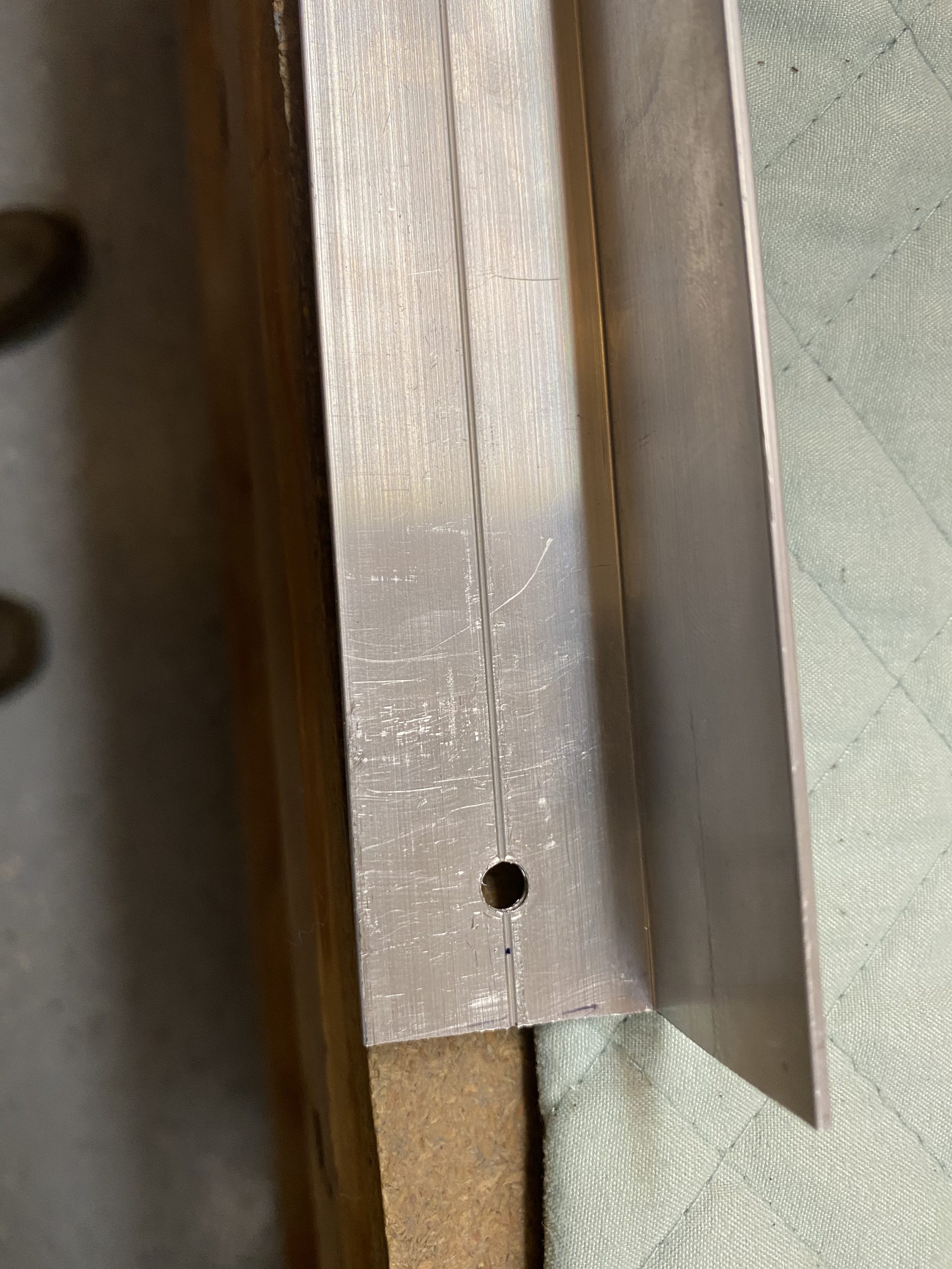
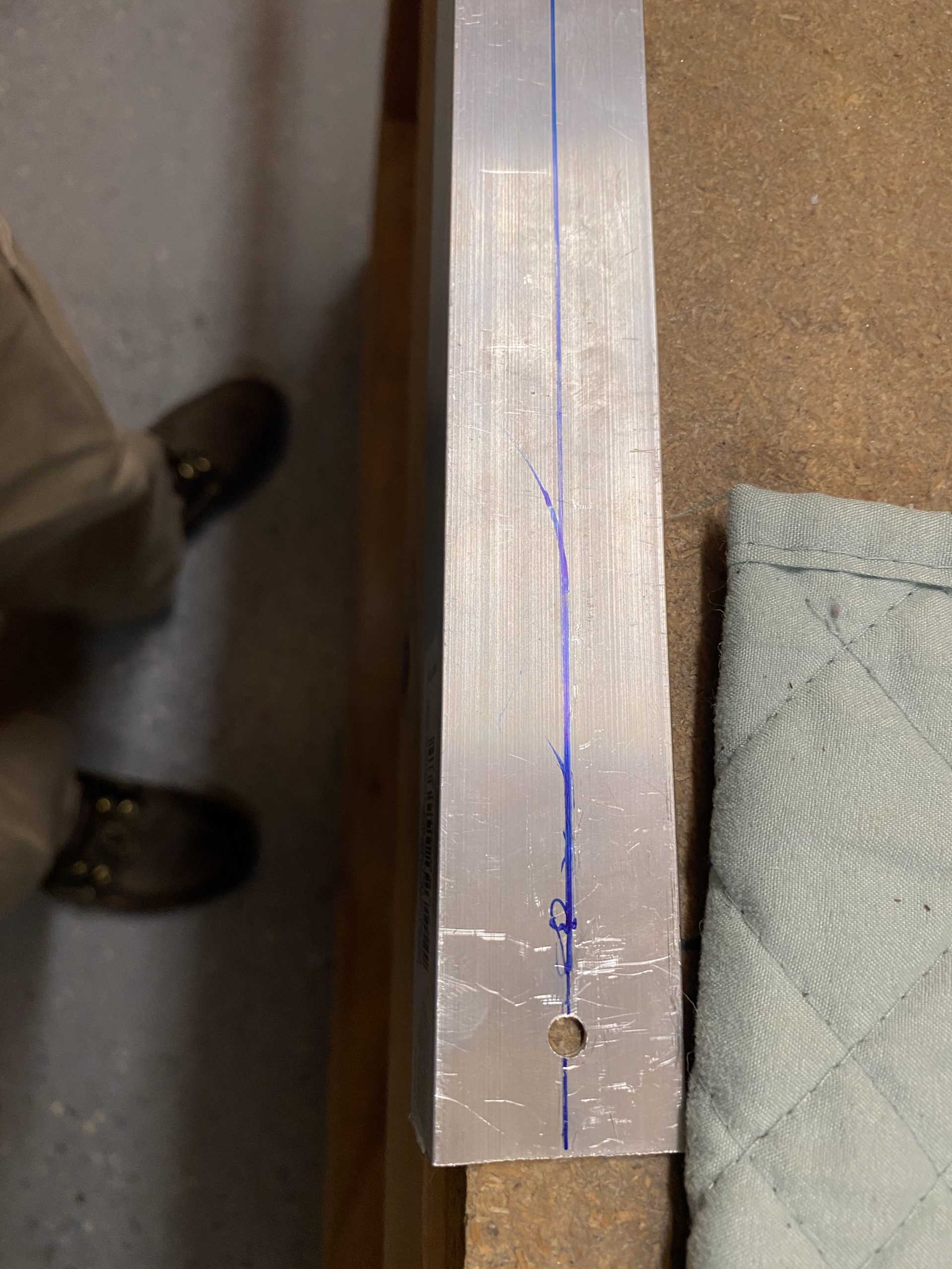
Then, I marked a matching line on the opposite of the angle, right down the center so I could locate the centerline using the top tooling hole in the rib, and backdrill into the angle.
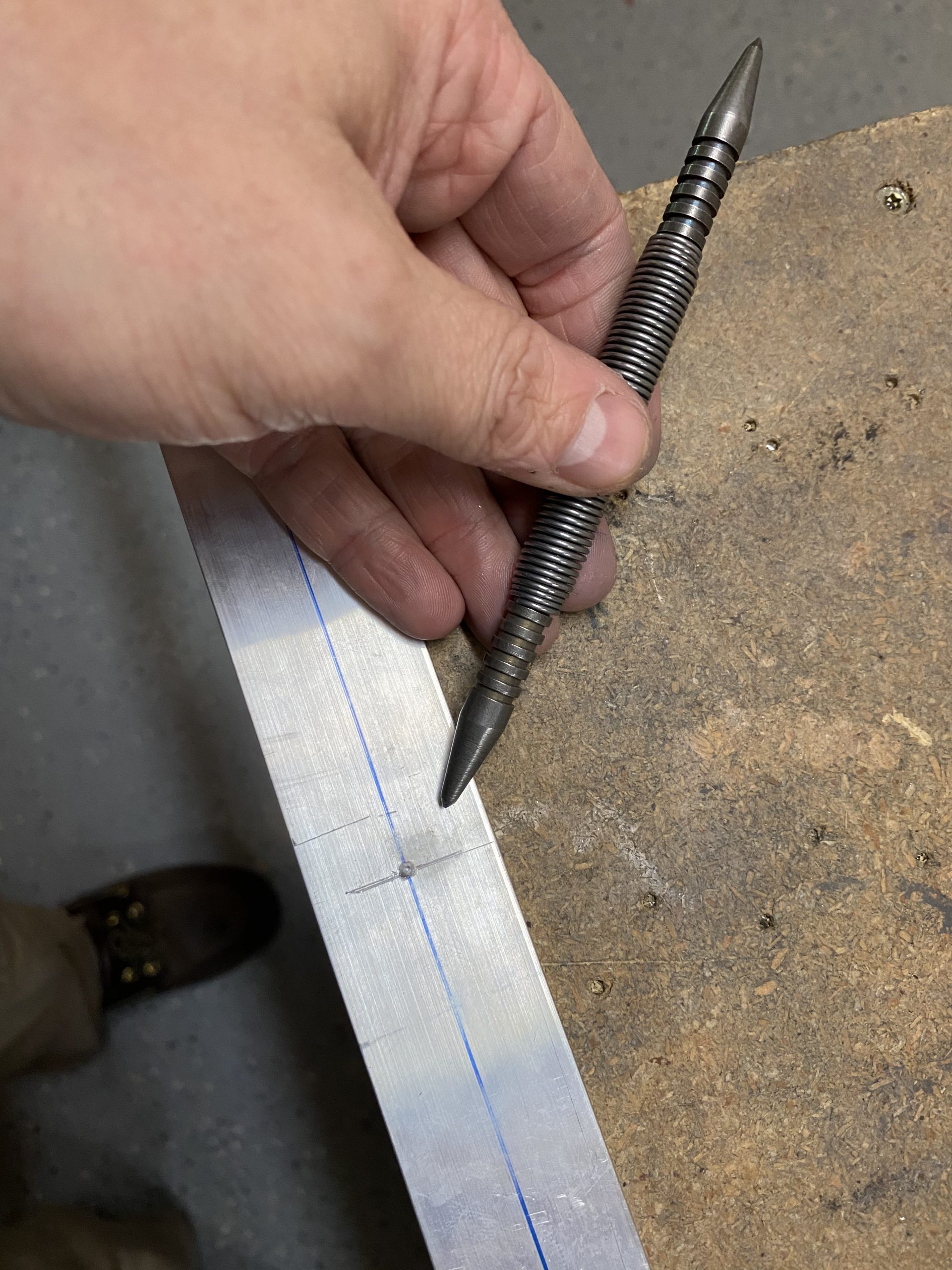
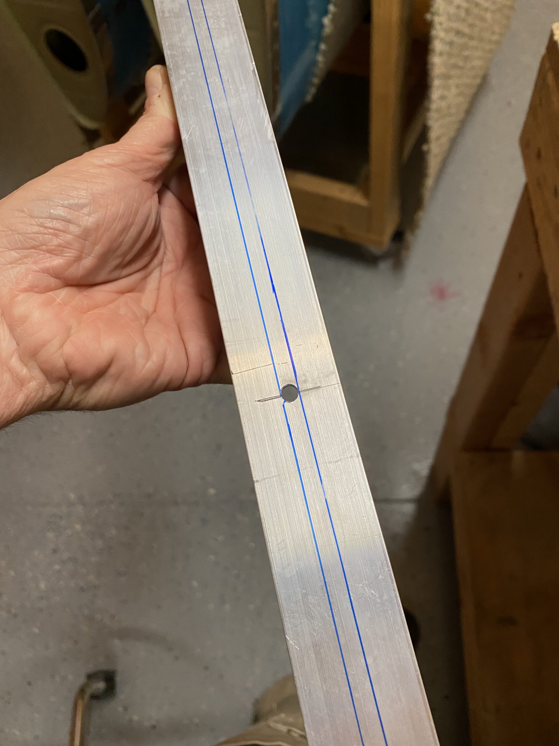
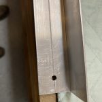
Next, I fitted the angle to the rib, bolting the bottom hole of the angle to the bottom (leading edge) hole of the rib. I wantcd to locate where to drill my top hole in the angle, so I took the #12 drill bit in my hand, stuck it through the tooling hole in the rib, and scored a witness mark on the angle by rotating the angle against the drill bit. This give me a perfect witness mark and cross hairs to drill the top alignment hole.
 .
. 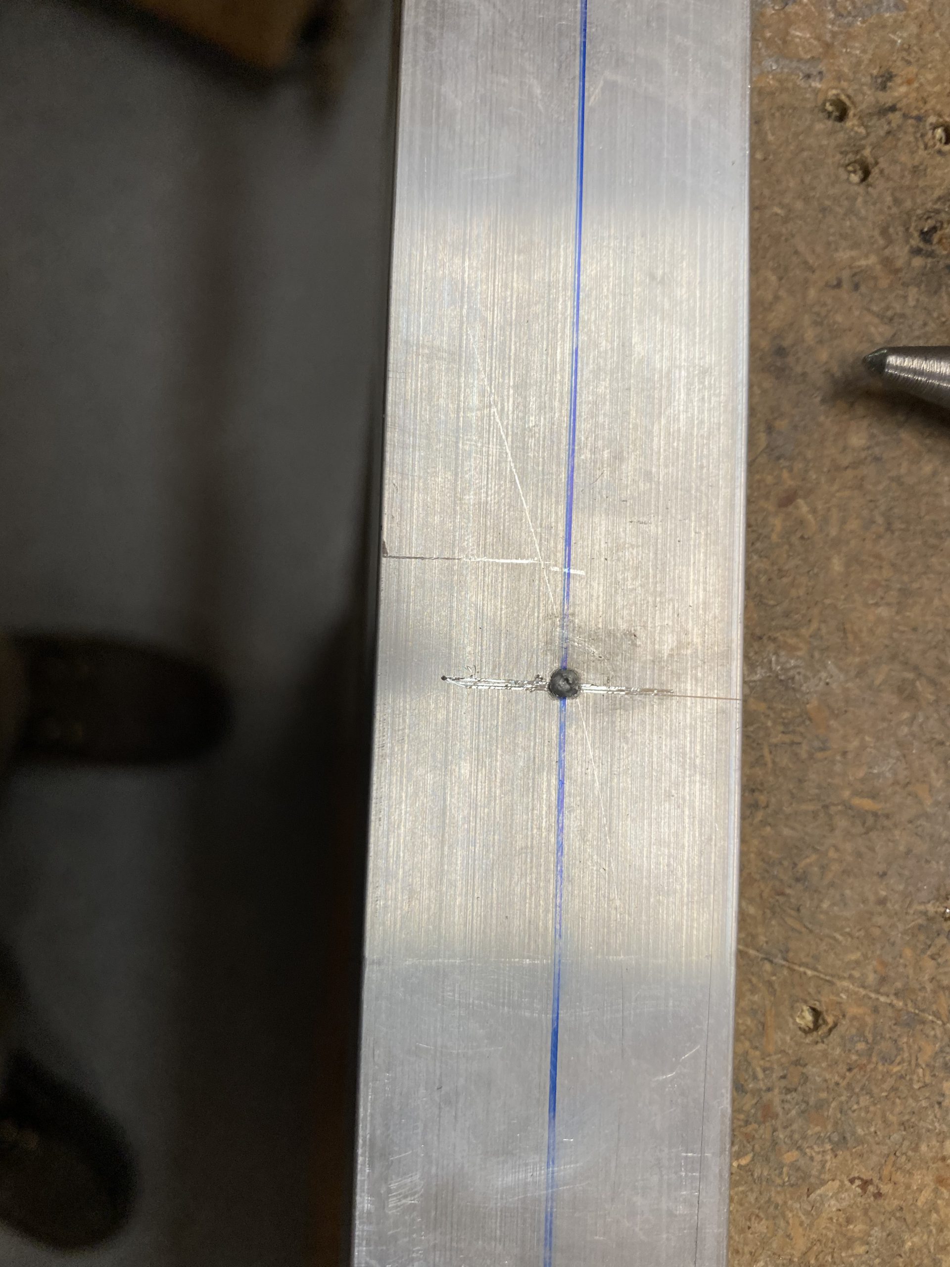
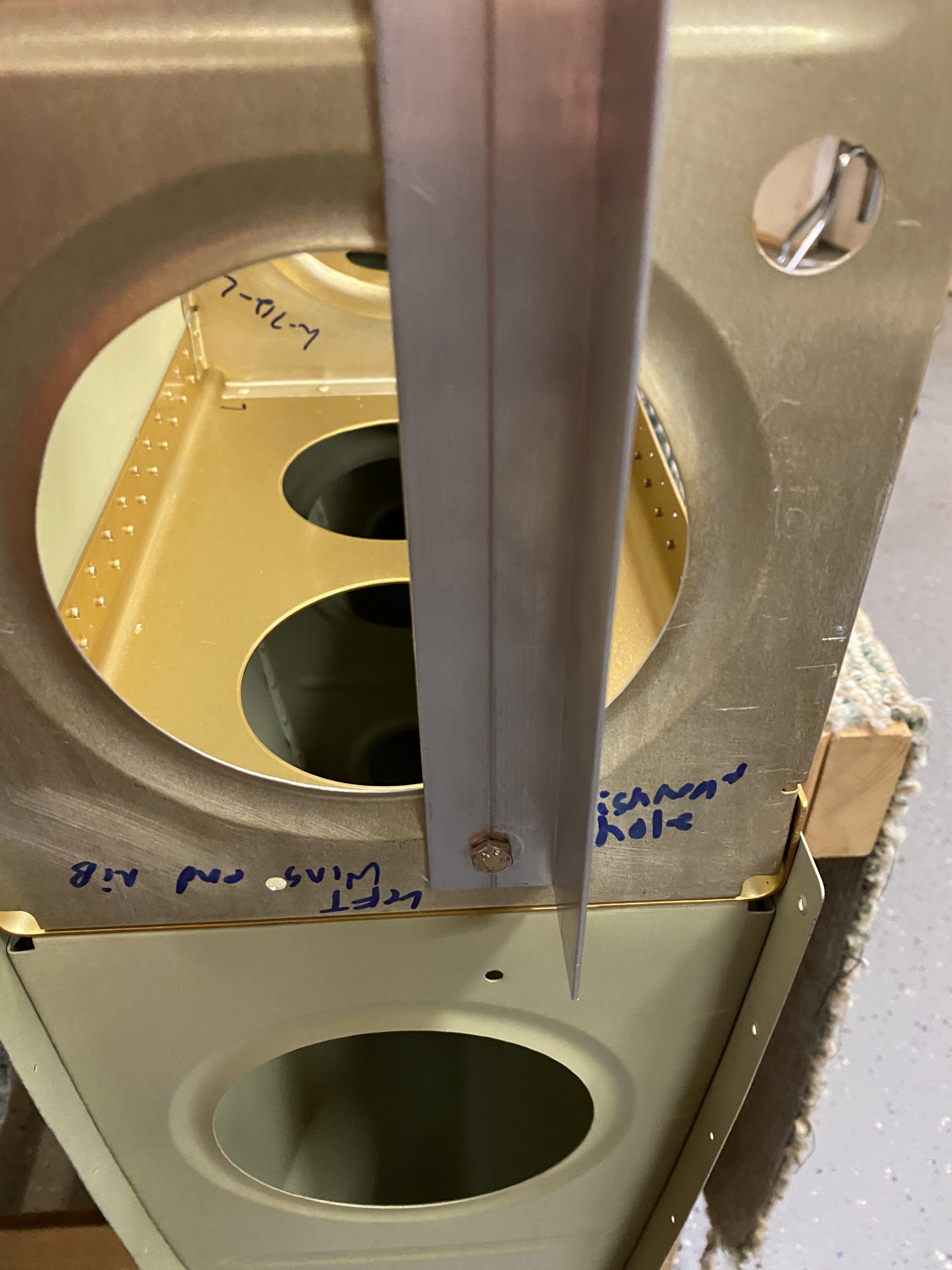
The photos above shows the scored mark, and me using a noxon center punch on this mark to make a staring spot for my drill bit. I simply drilled a #19 hole where this center punch was, and then test fit my new holes against the two tooling holes in the rib, and they fit very nicely! The AN3 bolts fit a little snuggly, but thats perfect. Heres a photo showing with it clecoe’d in place to test fit.
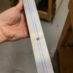
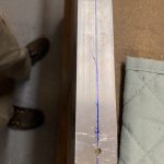
We’re not quite done. I still needed to draw the two alignment marks using the two new holes as my alignment points. See that drawing above, we have to use these two holes, and draw a straight line using the tangents off each of these holes, all the way out to the end of the jig, so we can reference the lines with the aileron’s trailing edge to make sure its in perfect neutral alignment. So, I used a 48″ ruler as my straight edge, and clamped the ruler, and my new jig down to the edge of the workbench, lining up the top of the holes against the ruler so I can draw my tangent lines.
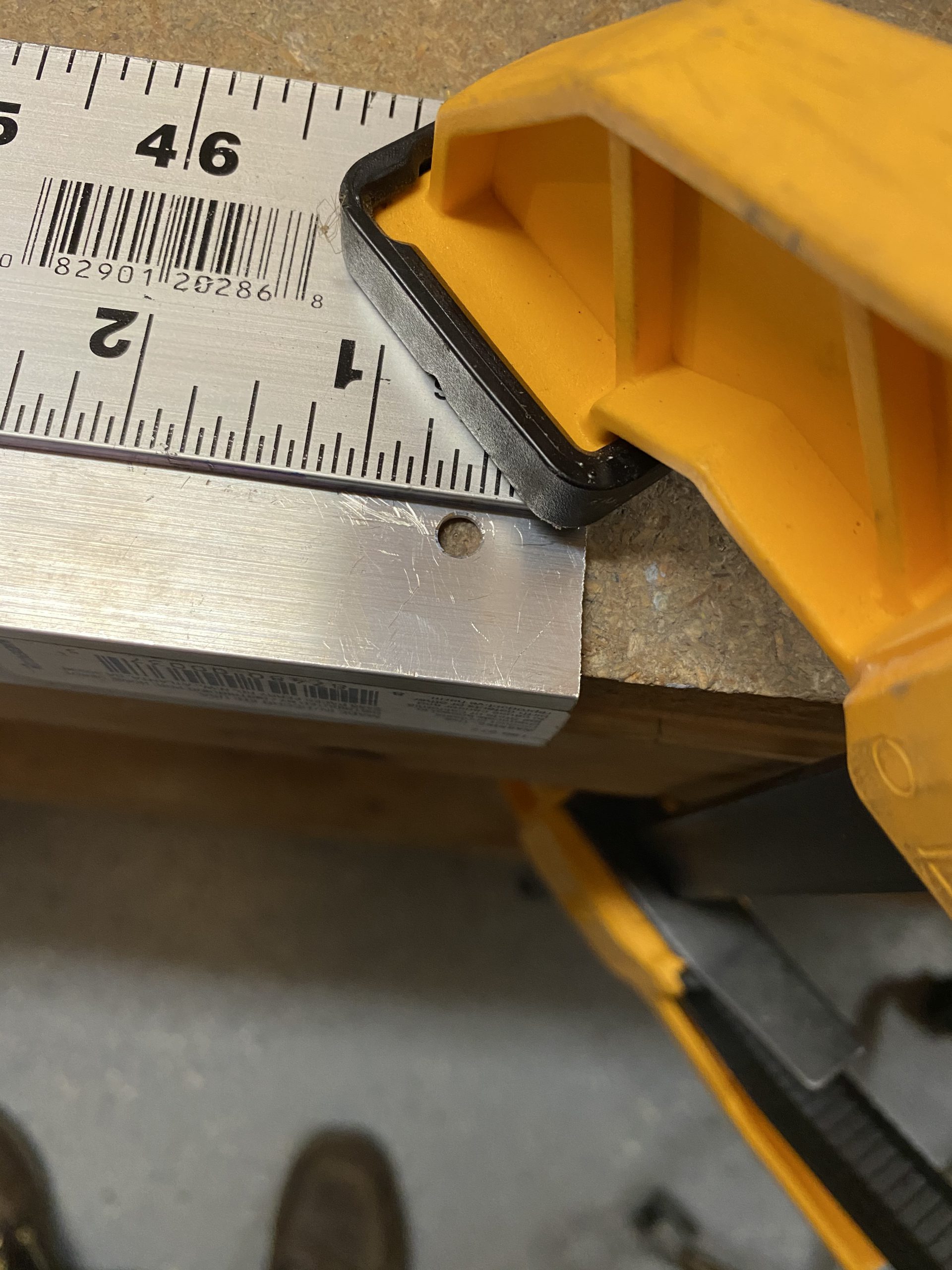
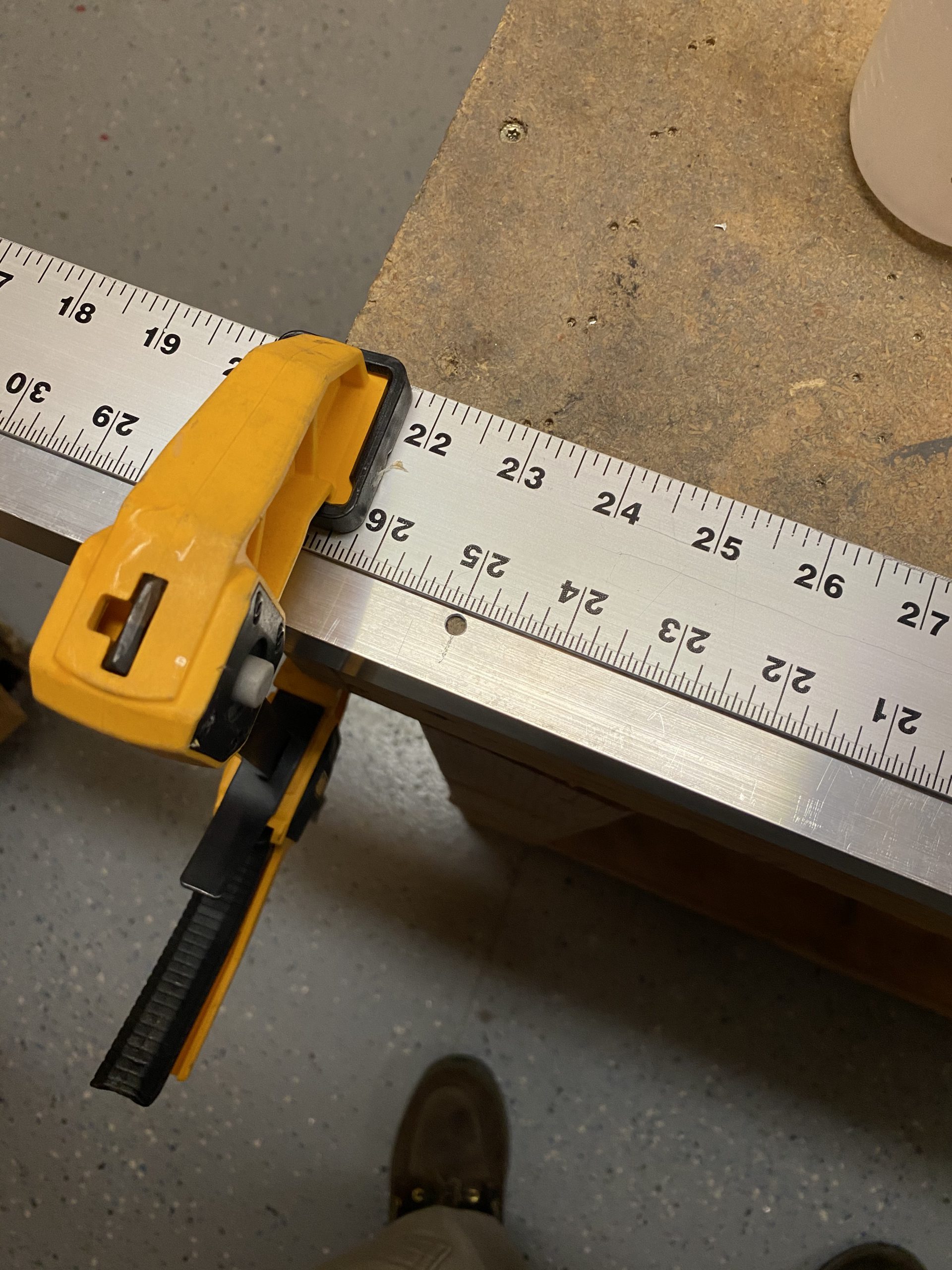
Then I grabbed a fine point sharpie, and made a nice straight line all the way from one end of my jig to the other, using that ruler as my guide. Once I had the top tangent line done, I repositioned my ruler to do the same for the bottom tangent line. I don’t know how precise I was, but I think its certainly close enough to get the aileron into alignment:
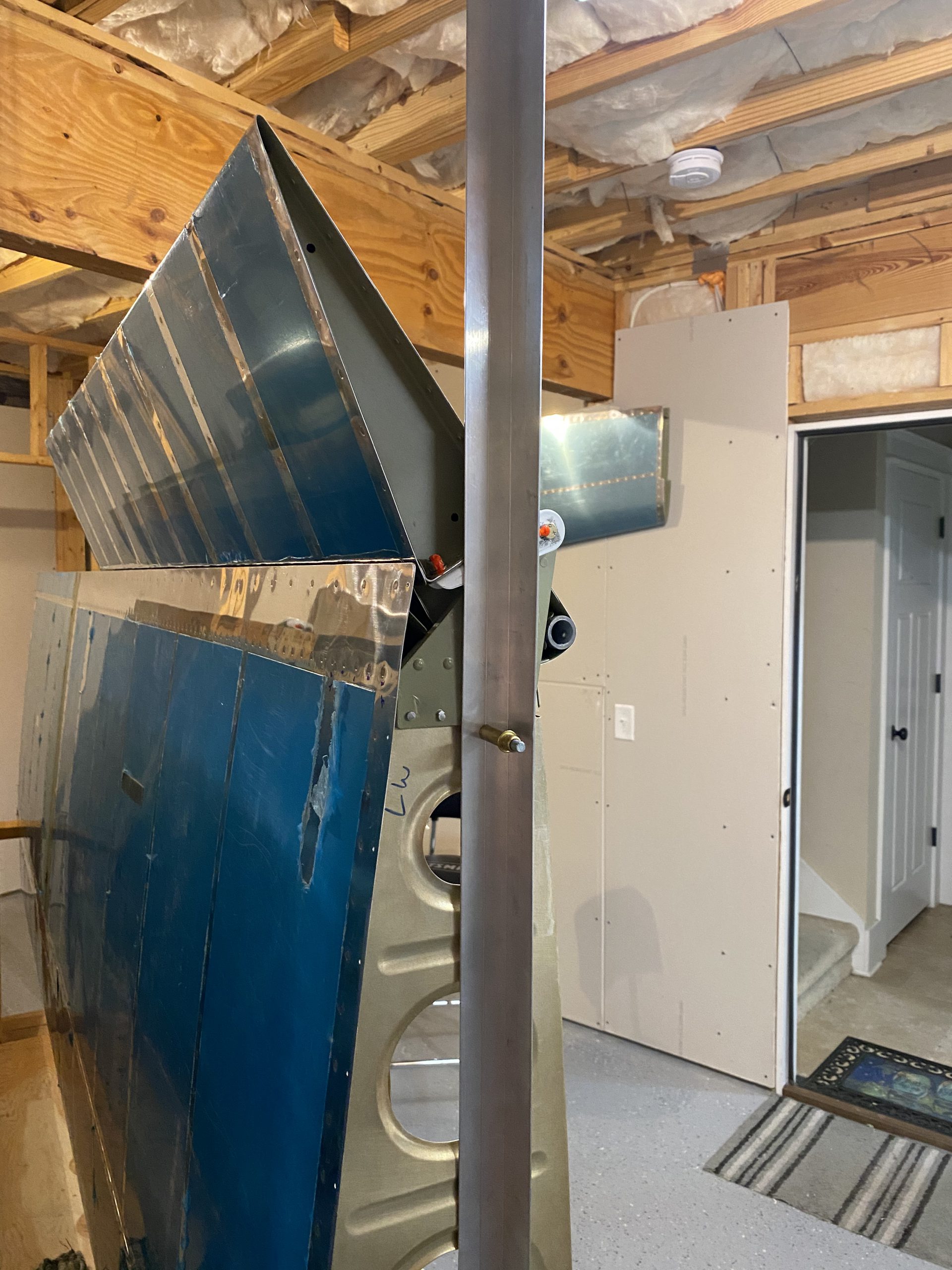
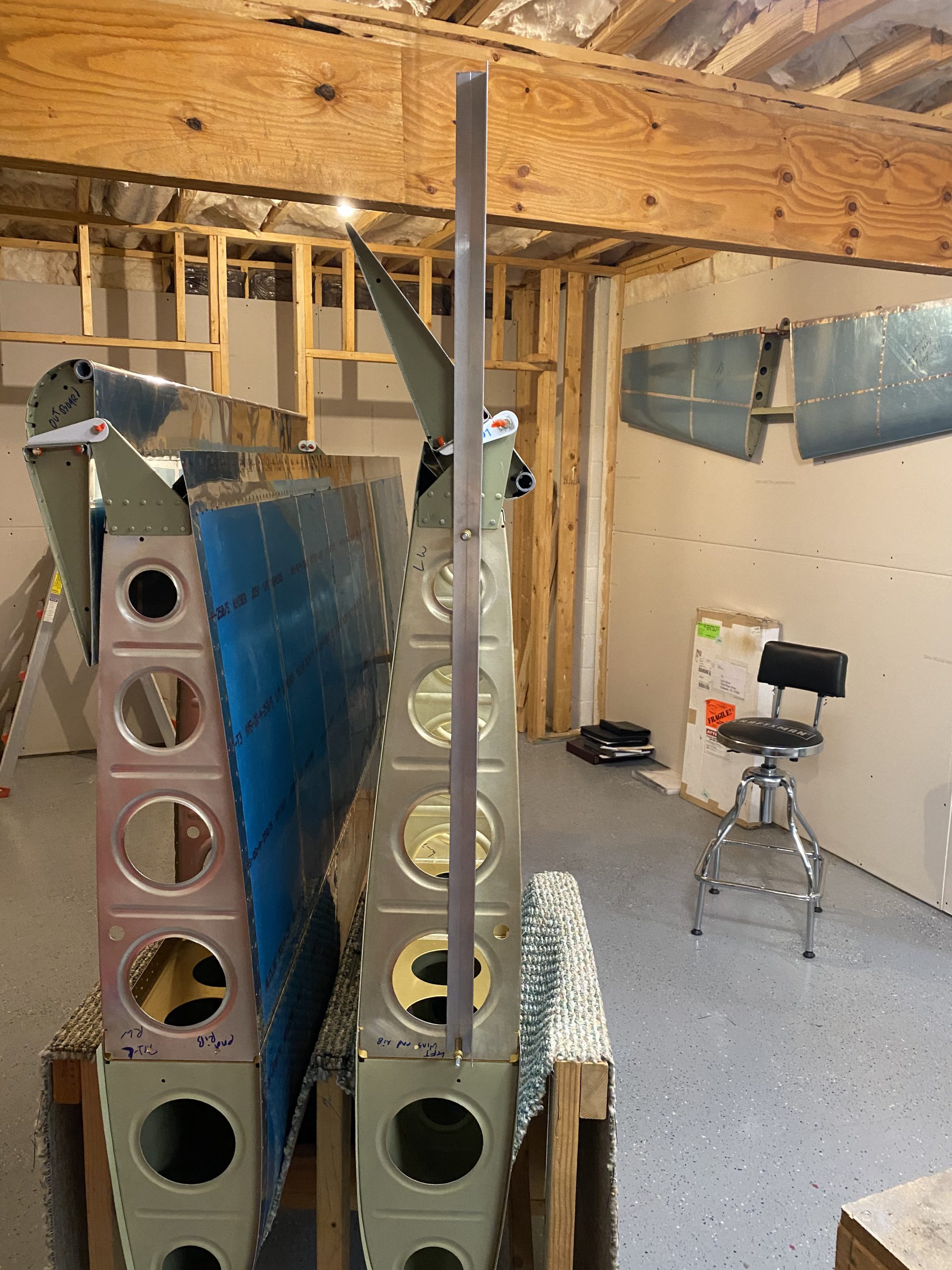
Lastly, I bolted the jig onto the wing using the tooling holes in the rib and some AN3 bolts and nuts and it looks like its going to be super easy to get the aileron into alignment.
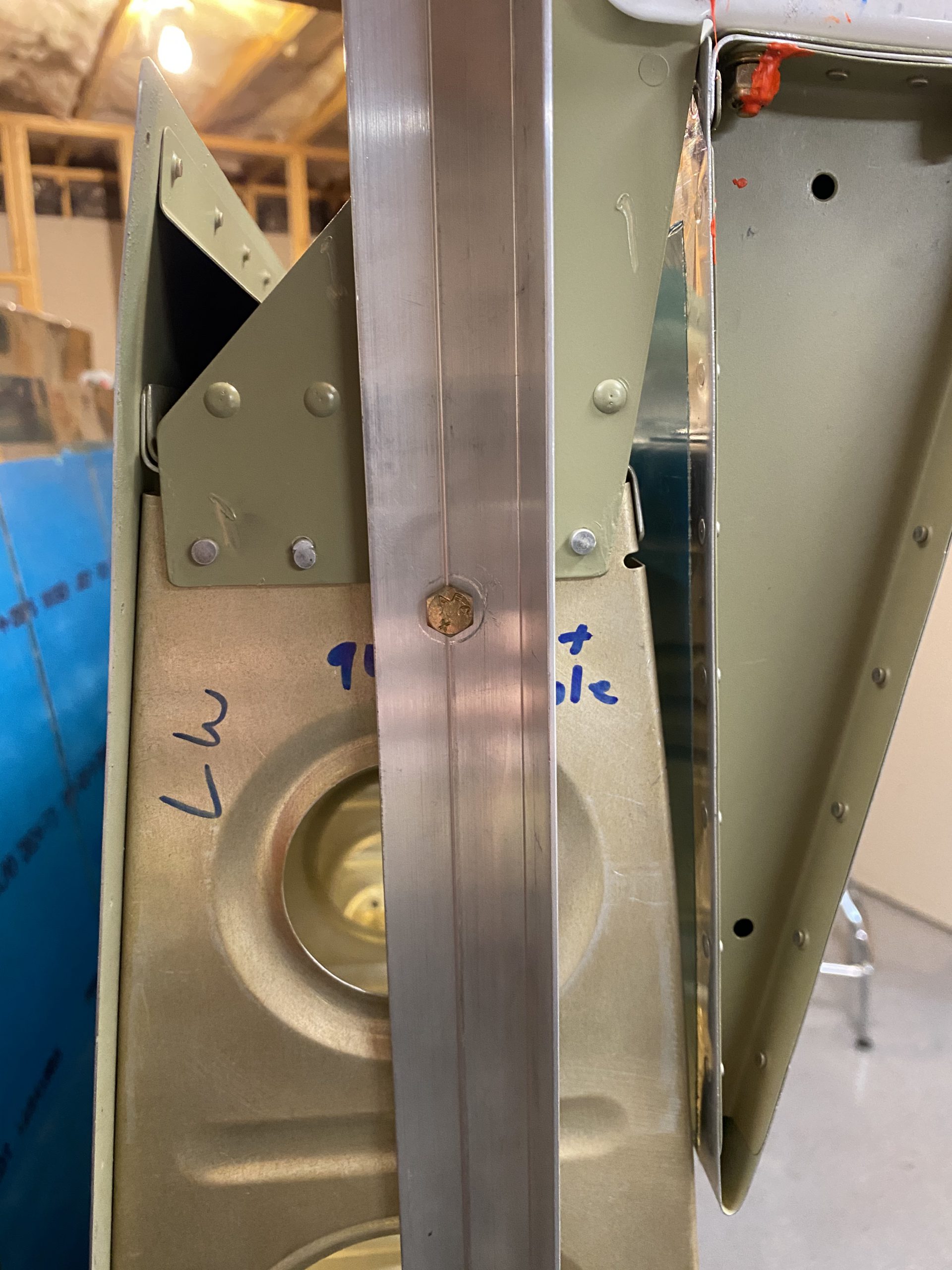
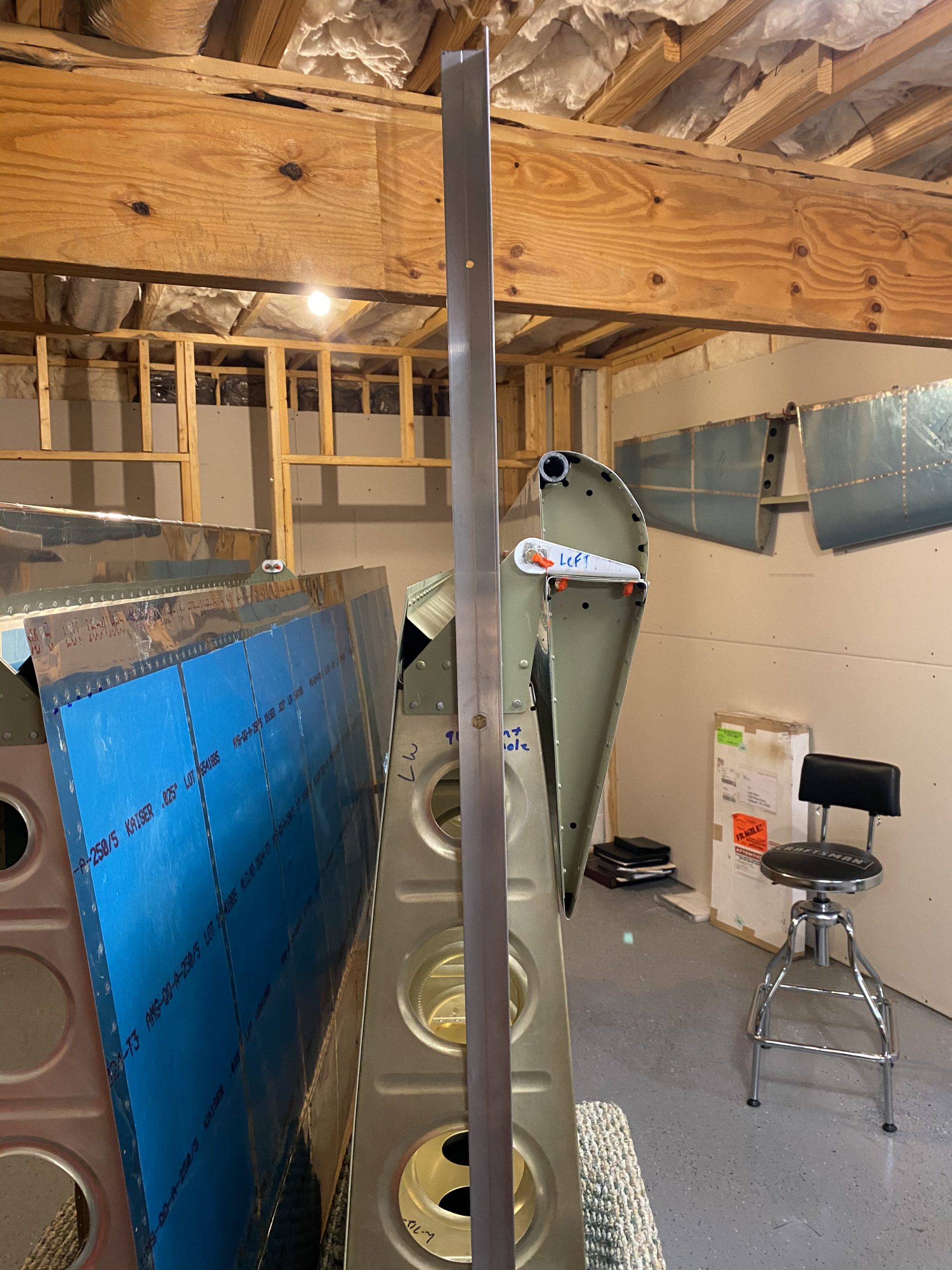
I also marked on the rib with some sharpie “ALIGNMENT HOLES” and circled the holes, just in case I need to re-align this aileron in the future. Who knows, It may never need rigging, but its there just in case to avoid any confusion. Then I sat down at the bench and looked over the plans a bit to start game-planning my next work session. The only thing really left is to install the nylon wiring conduit, but I think I want to wait on that so the conduit doesn’t get in the way of adjusting the pushrods. I think I am at a “critical path” in my build: Waiting on the pushrod parts to get here. Thats all for this build session. I’ll take photos of aligning the aileron using this new jig once I get the replacement pushrods made.
Google Photos Link: https://photos.app.goo.gl/p45ETLqTMKnDQBNYA
-
IMG_3038
-
IMG_3050
-
IMG_3049
-
IMG_3048
-
IMG_3047
-
IMG_3046
-
IMG_3045
-
IMG_3044
-
IMG_3043
-
IMG_3042
-
IMG_3041
-
IMG_3040
-
IMG_3039
-
 12A_7_8-Wing_Miscellaneous (1 page) 2020-10-18 at 10.26.22 PM


Hours Worked: 1.0