Disassembling Horizontal Stab for Priming

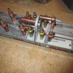
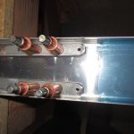
Tonight I started disassembling the horizontal stabilizers to prepare them for priming. This the last step in the “Drilling the horizontal stabilizer” section of the plans.

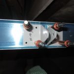
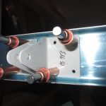
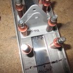
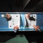
I started by unclecoing the skin from the right stabilizer, and marking it and all the parts of the skeleton as I removed them. Noting their orientation and layout. Once I had the right side done, I did the same on the left, and kept all their respective parts in separate stacks on my parts shelves.

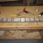
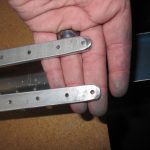
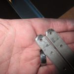
After they were all took apart, I finished drilling the HS-710, HS-714 and HS-00001 parts per the instructions. I needed to drill the last few holes on the bent part of the spar bars to match the HS-702 and HS-00001 doubler. This only took a few minutes to complete, since it was only a few holes. However, I do have a question about some of the extra holes in the HS-00001 that I am going to ask the forum about, and possibly Vans.

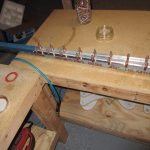
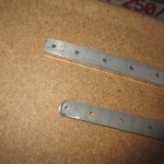
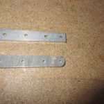
Next, I started on the left stabilizer skeleton parts but deburring the holes and finishing the edges. I also took care of the edges of the lightning holes. I didn’t get all of the parts done for the left stabilizer, but I got a good majority of them. I’ll leave the rest for another day. Once I have them all deburred and the edges smoothed, I will dimple the ones needing flush rivets and then get ready to paint them all (hopefully this weekend).


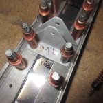
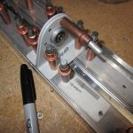
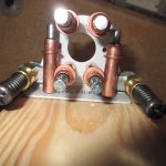
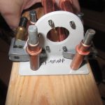
Here’s the photos of tonight’s work: https://goo.gl/photos/6vPJvvS4wQvg26Ym6

Hours Worked: 3

Drilling Right Horizontal Stabilizer

Today I worked on the right horizontal stabilizer. Technically I completed the “Drilling the horizontal stabilizer” section of the plans, save for the riveting.

Todays session was pretty much identical to the last one, except I was completing the right side horizontal stabilizer as opposed to the left from the previous session.

In summary, I clecoed the ribs, then match drilled them to form the skeleton. Then I worked on fitting the HS-00005 and HS-00006 ribs into the skeleton and marking, and back drilling them. The tedious part was the measuring and aligning, and then clamping everything to drill.

Once they were good to go, I started back and match drilling the skins to the ribs and spars. That wrapped up the session for the night. To finish out this subsection, I will disassemble both sides so that I can prep them for priming and riveting.

Thats going to include:
1. Deburring all the holes
2. Scotchbrite all the edges
3. Rounding any corners
4. Scuffing the surfaces
5. Cleaning everything with acetone.
6. Spraying Akzo
7. Dimpling the skins and ribs
8 Riveting everything together.


Heres the photos from tonights work: https://goo.gl/photos/5XakAzTRj4FCnpic7

Hours Worked: 3.5

Drilling the Horizontal Stabilizer

Today was a good day on the project, with lots of progress being made, and ultimately a flying surface assembled. Tonights work began with going back a few steps in the plans to assemble the HS-00001 doubler plate to the front spar. I measured out where the edges should be … Continue reading

Front Spar Complete

After reading over the plans and instructions last night I decided to get to work today with a clear mind. I completed the Front Spar Assembly section of the empennage section with the exception of deburring, dimpling and priming. I am going to combine as many of the parts as … Continue reading

Front Spar Assembly

Today I started the “Front Spar Assembly” of the tail kit. After feeling good about the rear spar, I figured this would be just as easy. That wasn’t the case. I spent much of my time just looking at the planes and holding parts together to visualize what was needing … Continue reading

The Journey begins!

Like every journey starting with the first footstep, I started my journey on the rear spar, like so many others who have gone this way before me.

I worked a solid 2.5 hours tonight. I didn’t want to push myself to do to much in my first session, and really wanted to just dig in and start cleco-ing stuff together to help motivate me.

Tonight I completed all the steps for the “Rear Spar” section of the first page on the plans. I found that using my bench grinder with a course wheel made quick work of the thick HS-609PP reinforcement bars. I had to break the edges and then taper the ends off. I rough outlines my shape with a sharpie and used the course wheel to work the metal down to the marks. Once i was happy with the rough shape, I used my file and the scotchbrite wheel to smooth the edges. I really like that scotchbrite wheel, its a great tool.

I am leaving the flat surfaces unfinished for right now, so I highlighted that step in my plans so i don’t miss it. I am going to prime the interior sections with AKZO, and I am going to try to consolidate all my priming so I will leave the surface as is, until priming day.

I made sure to mark that 8th hole on each side where HS-708 will attach so as to not rivet it by accident.

Then I moved on to building the HS-411PP bearing assembly. I actually picked up a good trick from George Ordorffs videos of drilling the VA-146 bearing assembly. I clamped HS-411APP and HS-411-BPP together u

sing cleco clamps. The I clecod those two down to a 2×4 block. I used BPP as a drill guide for APP and clecod to stabilize as I worked my way round. Once it was done, I test fit VA-146 between them and it fit beautifully. Deburr’ed the holes, and then sprayed VA-146 with some rattle can self-etching primer after I gave it a good roughing and cleaning. I will let it sit overnight to dry before riveting this assembly together.


Here is a link to the photos from tonights work: https://goo.gl/photos/Pk6pCY4hnbneTEA17

Hours Worked: 2.5