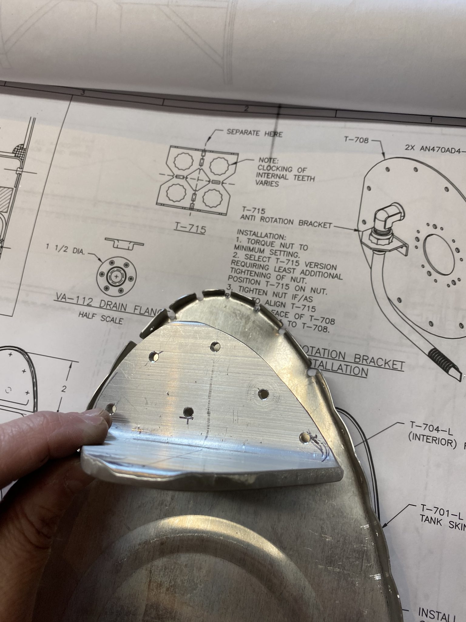
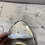
Get Online Xanax Prescription Short session to start today. I wanted to get the tank attach angles drilled, and after doing some reading last night, this actually seems straightforward. Vans gives us a rough idea of where to drill the rivets for the angle attach bracket in the plans with this drawing:
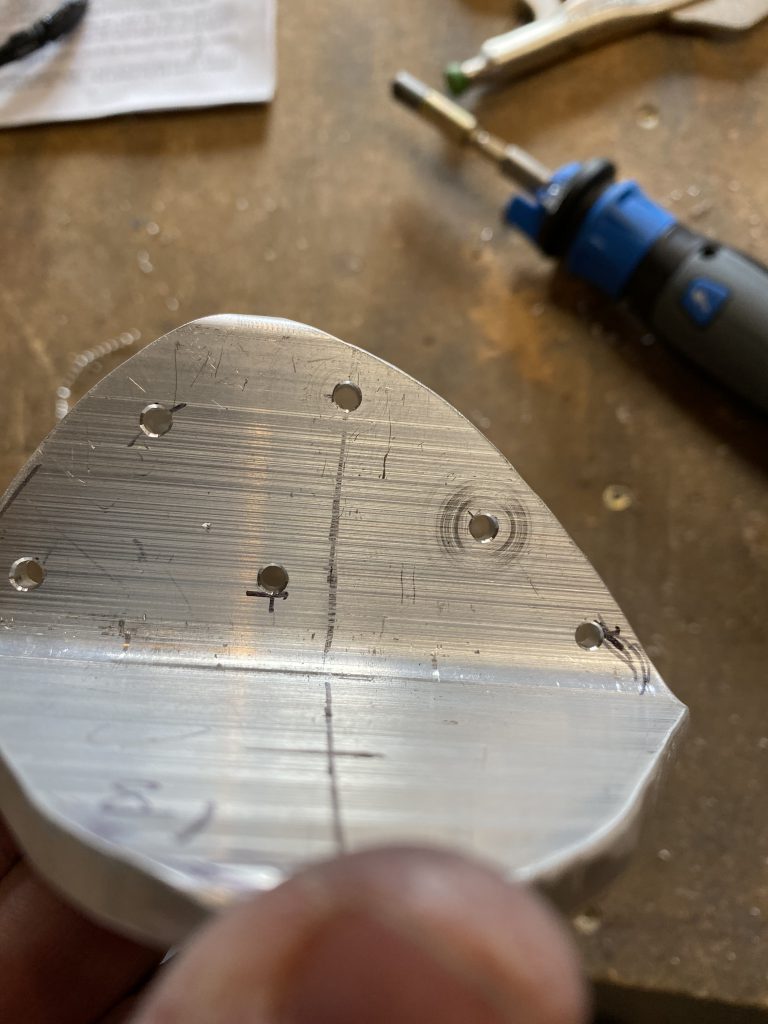
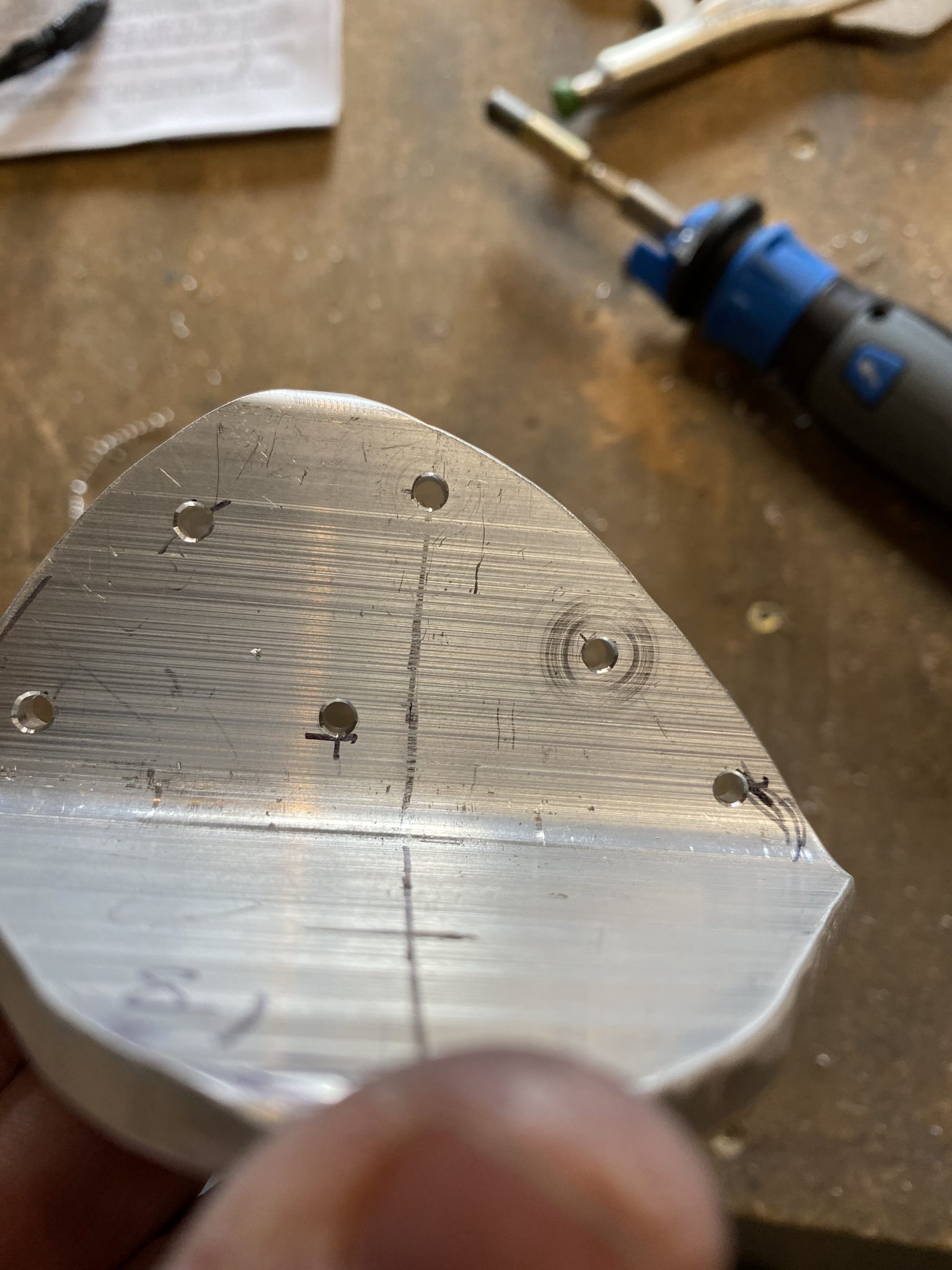
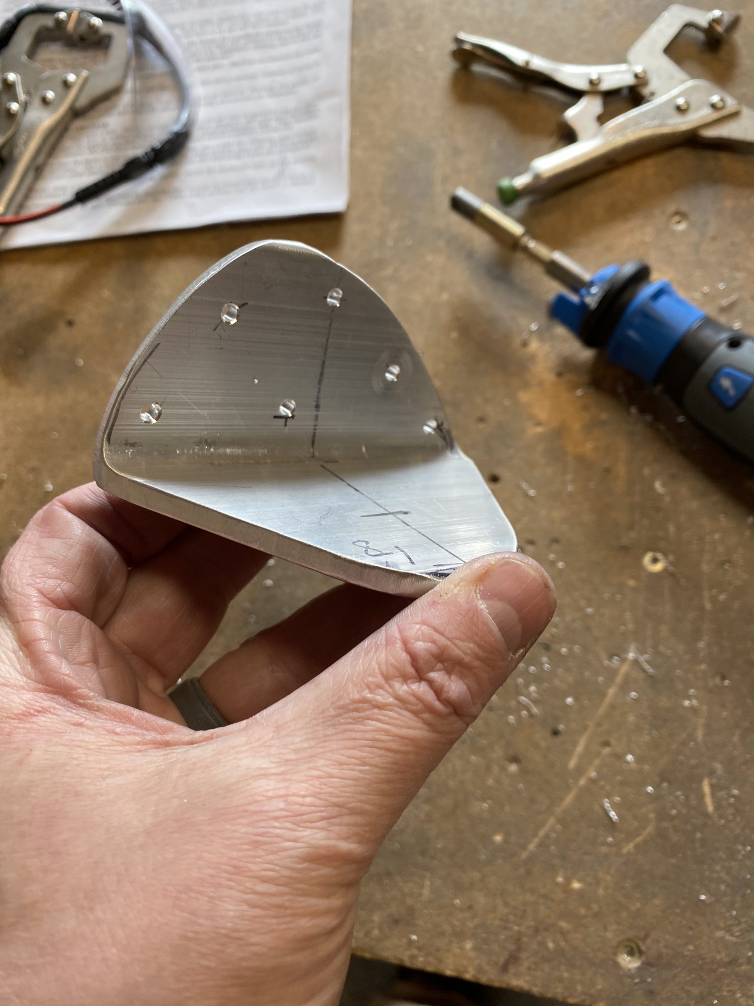
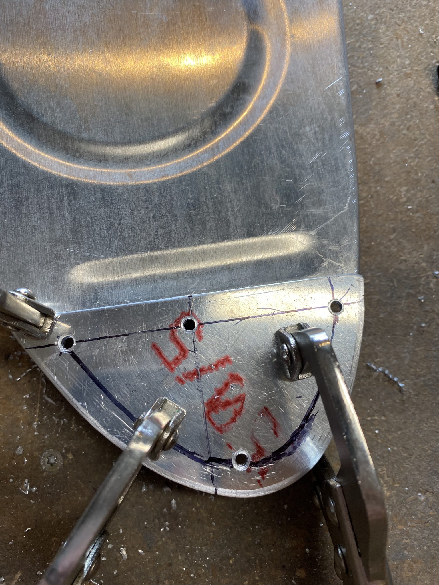
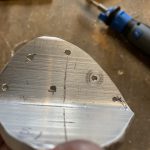
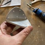
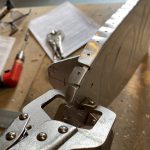
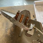
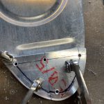
https://vietforent.com/contact/ We just need to be cautious of edge distance, so I used my square and made a few lines to give me plenty of edge distance, and then drilled the brackets with a drill press to get the holes nice and straight since these are chunky bits of metal.
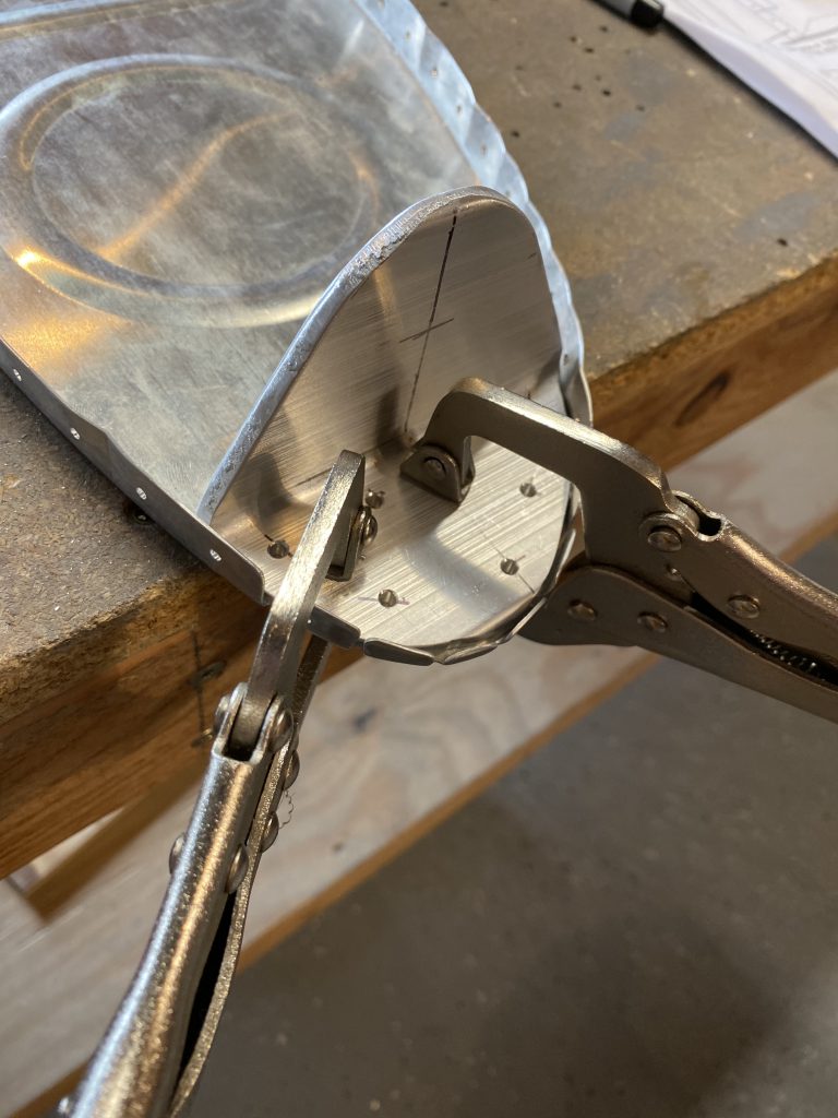
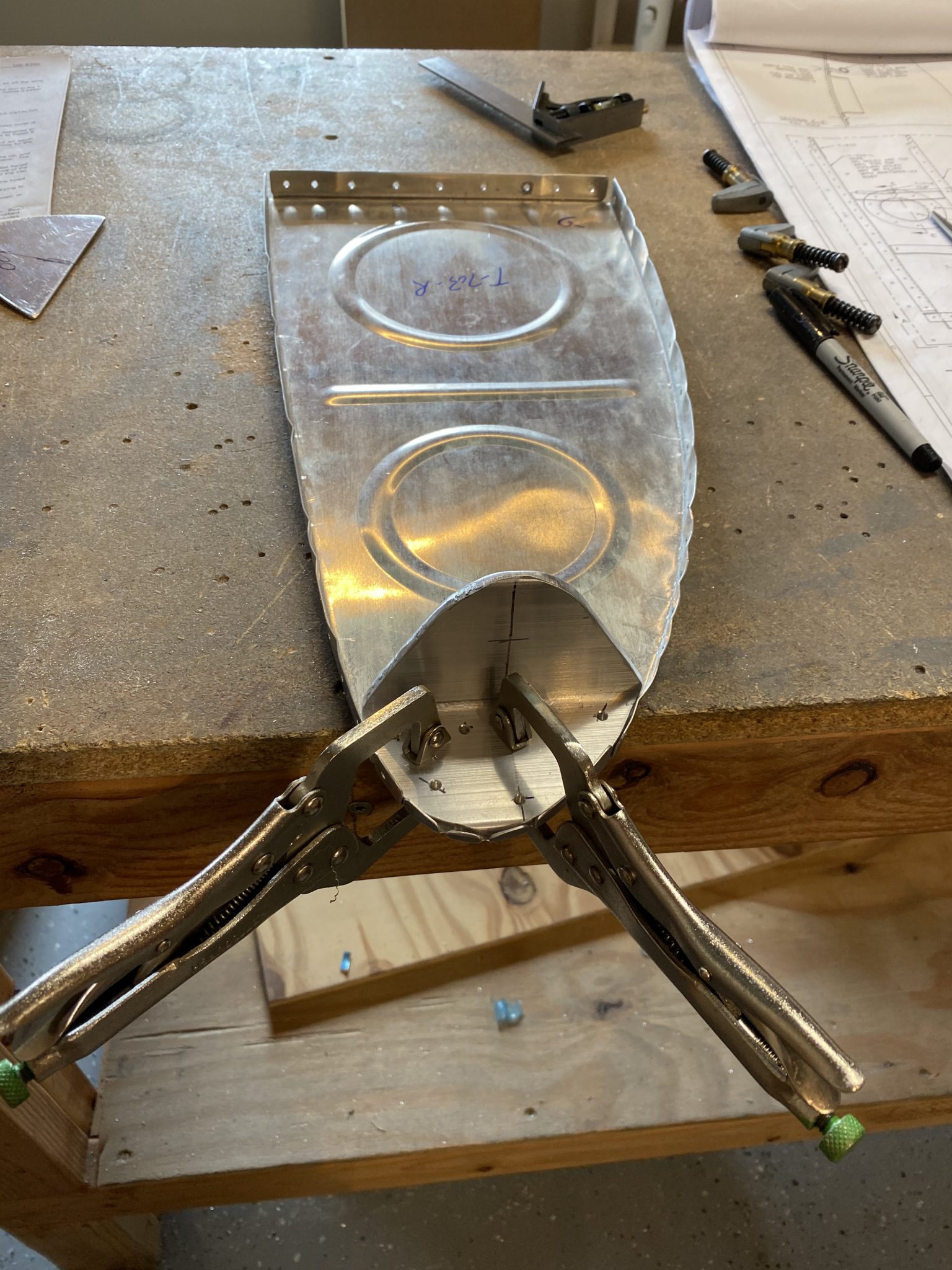
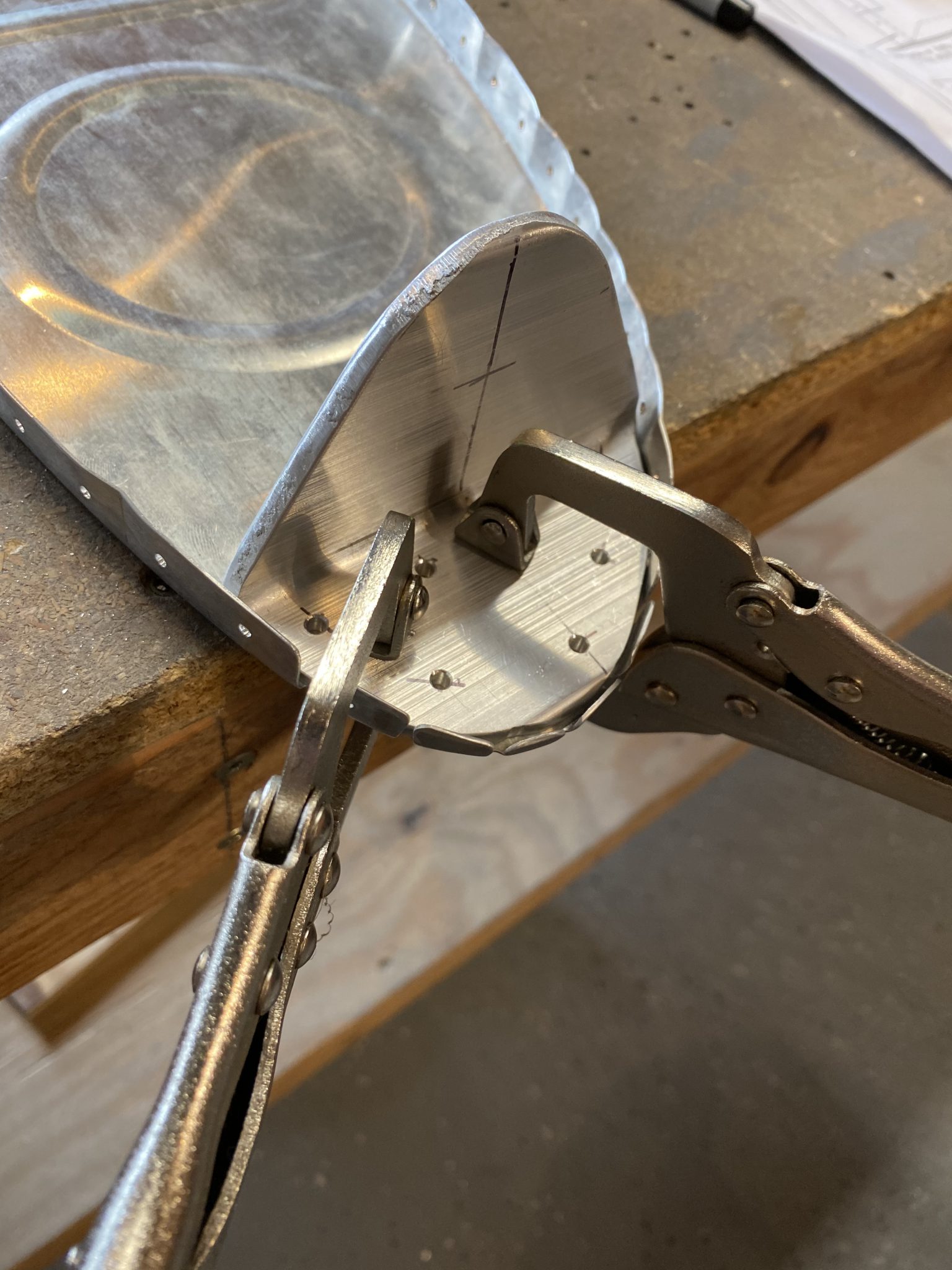
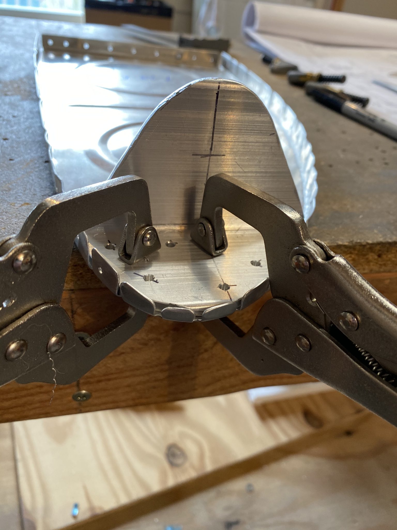
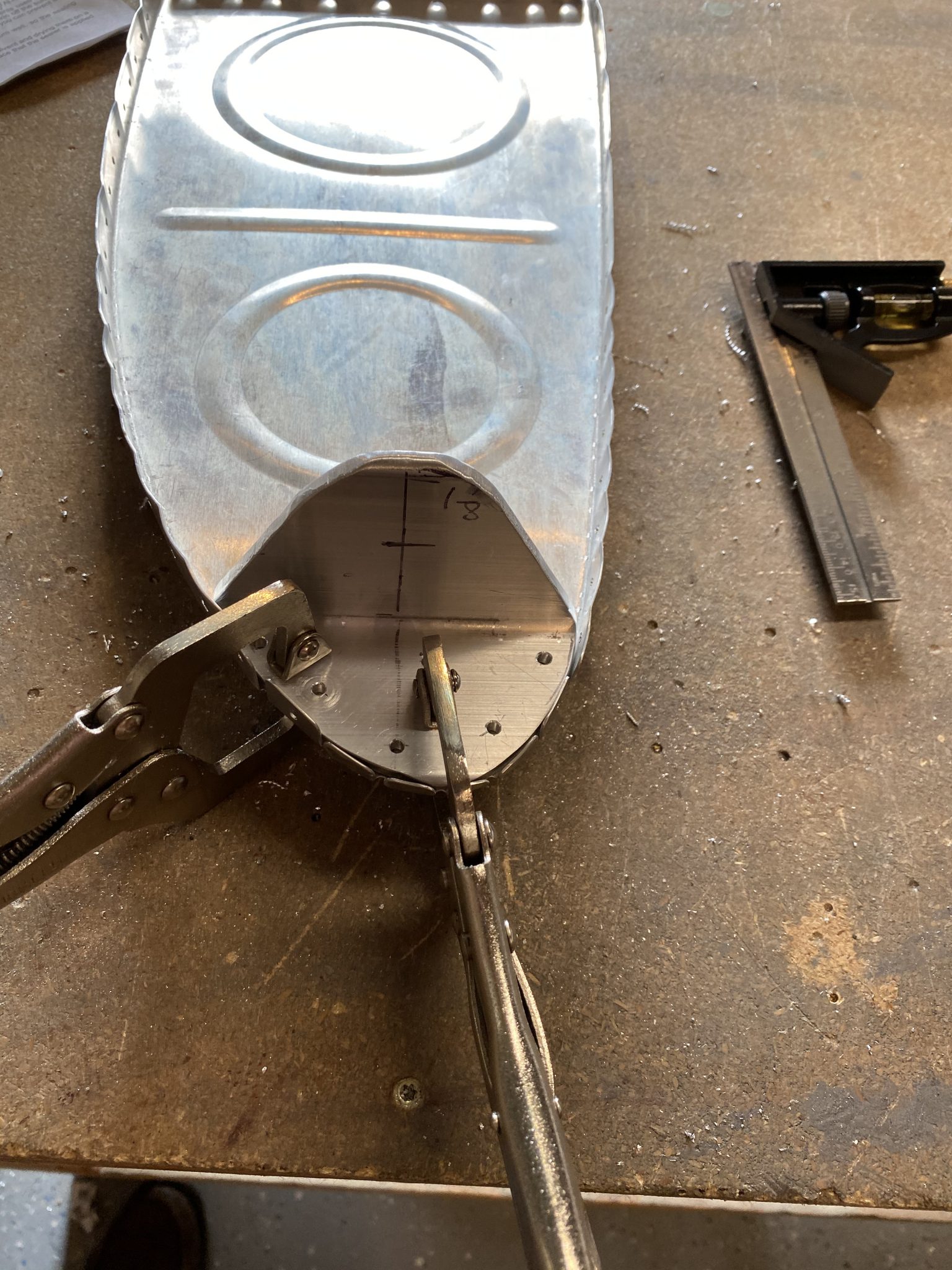
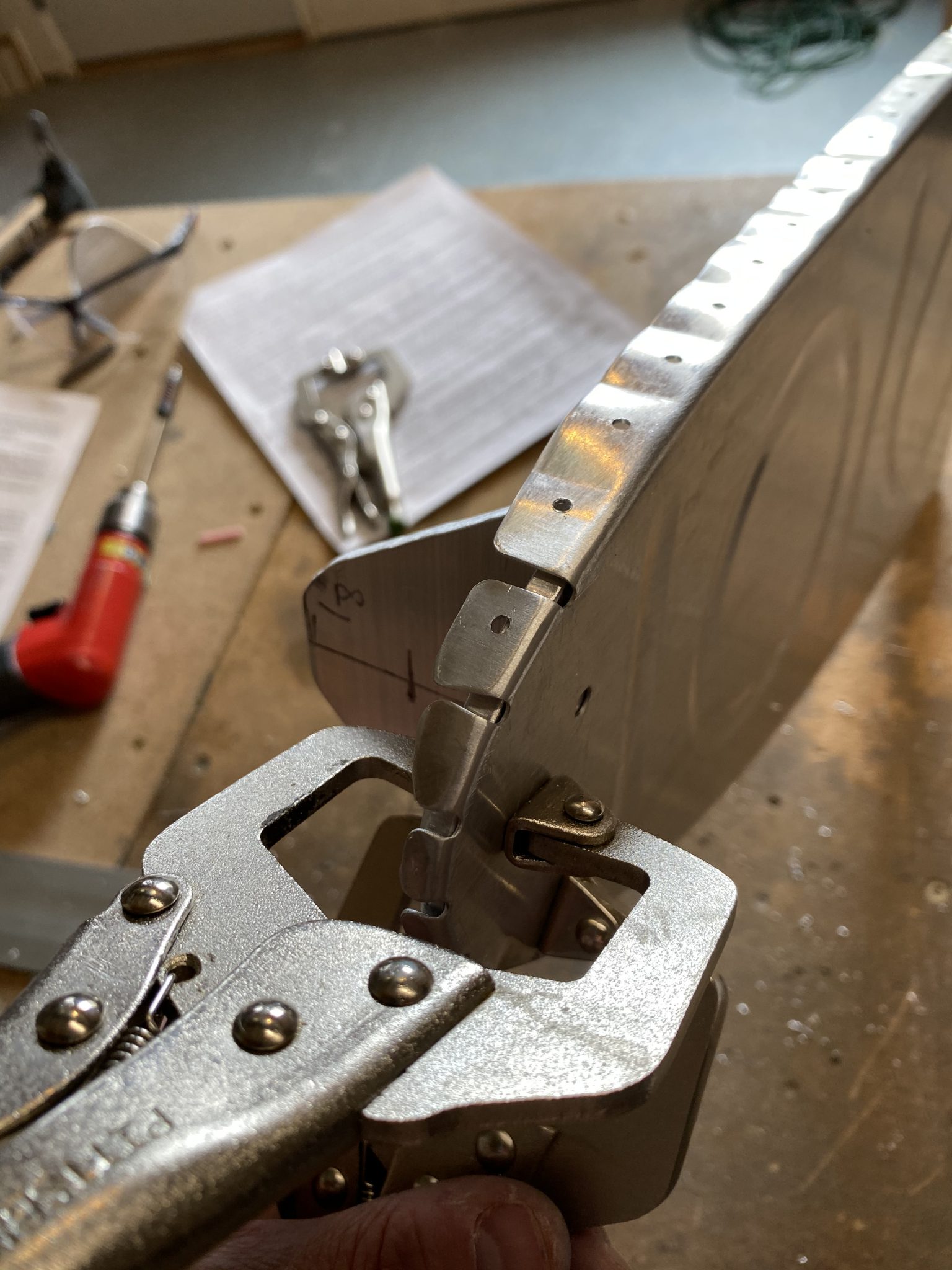
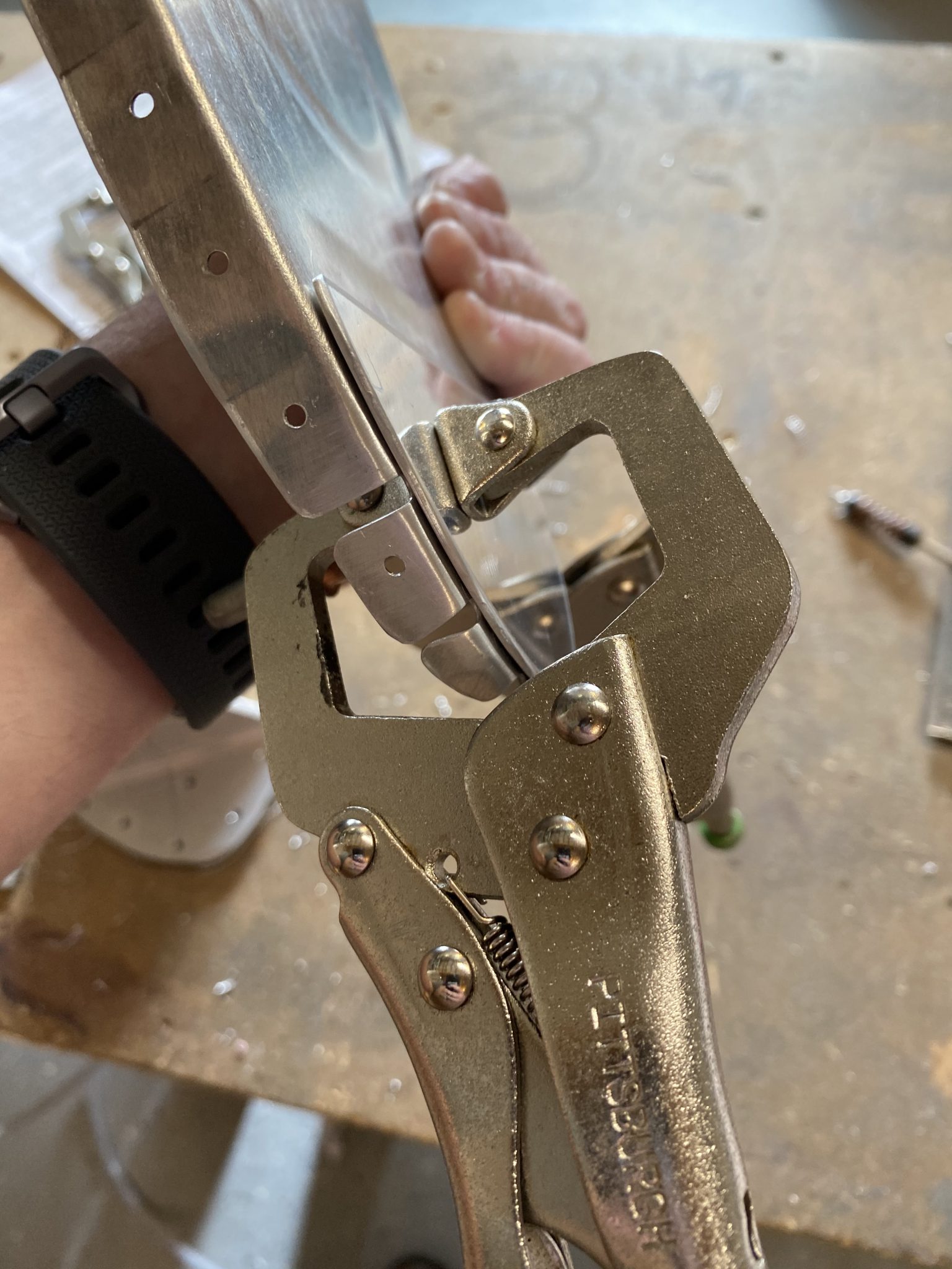
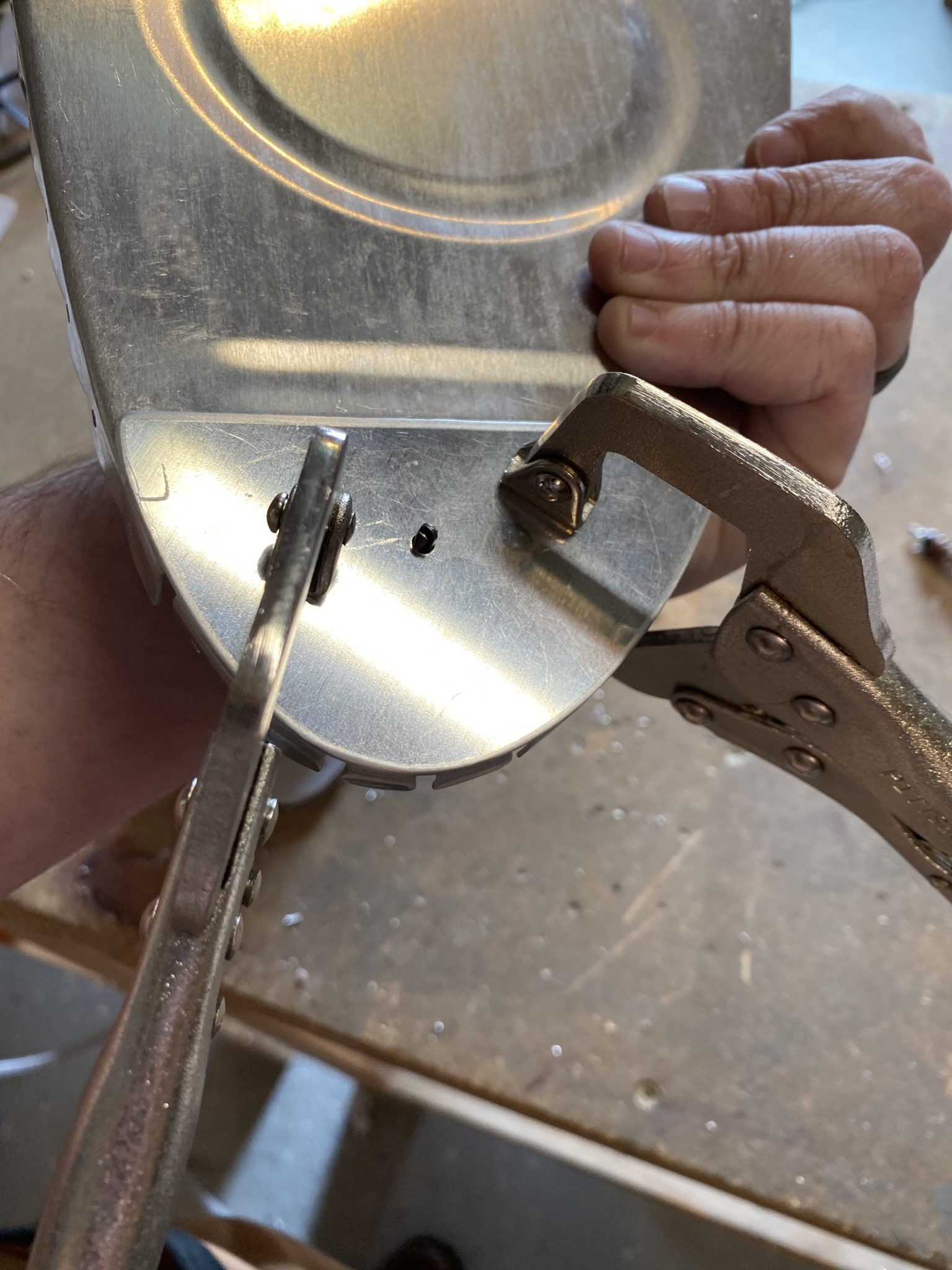
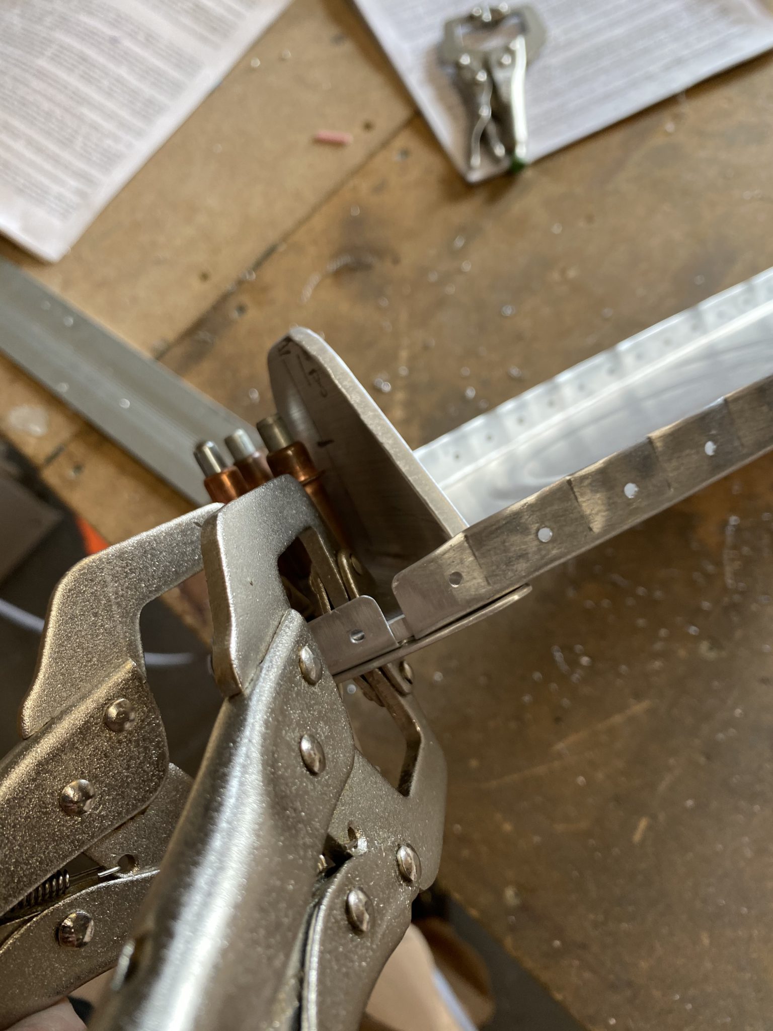
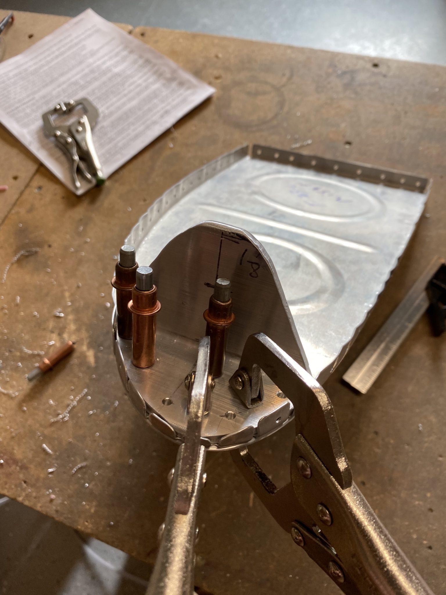
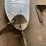
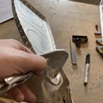
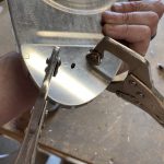
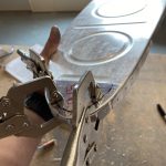
click here Then I deburred these holes, and placed the bracket into the rib and lined it up and nice and square so that I could use the bracket as a template to back drill the holes in the rib. I used some clamps to help hold it in place. Notice that I left off the reinforcement plate that goes on the back side of the T-703-R/L rib. I did that on purpose so it would be easier to line up.
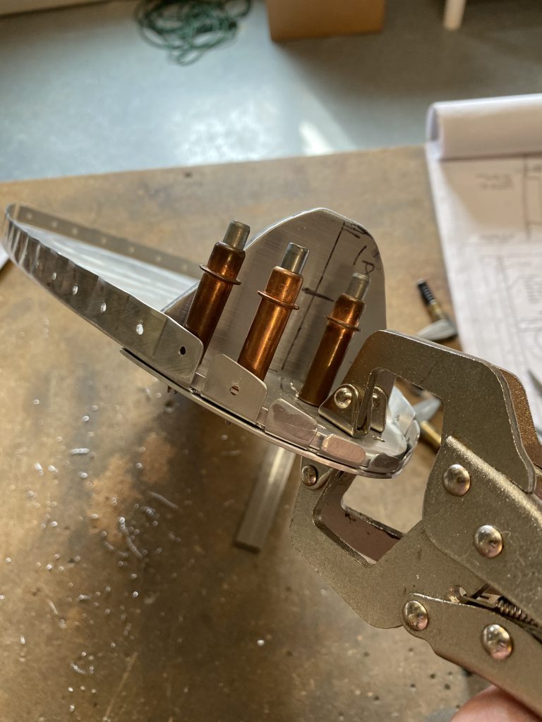
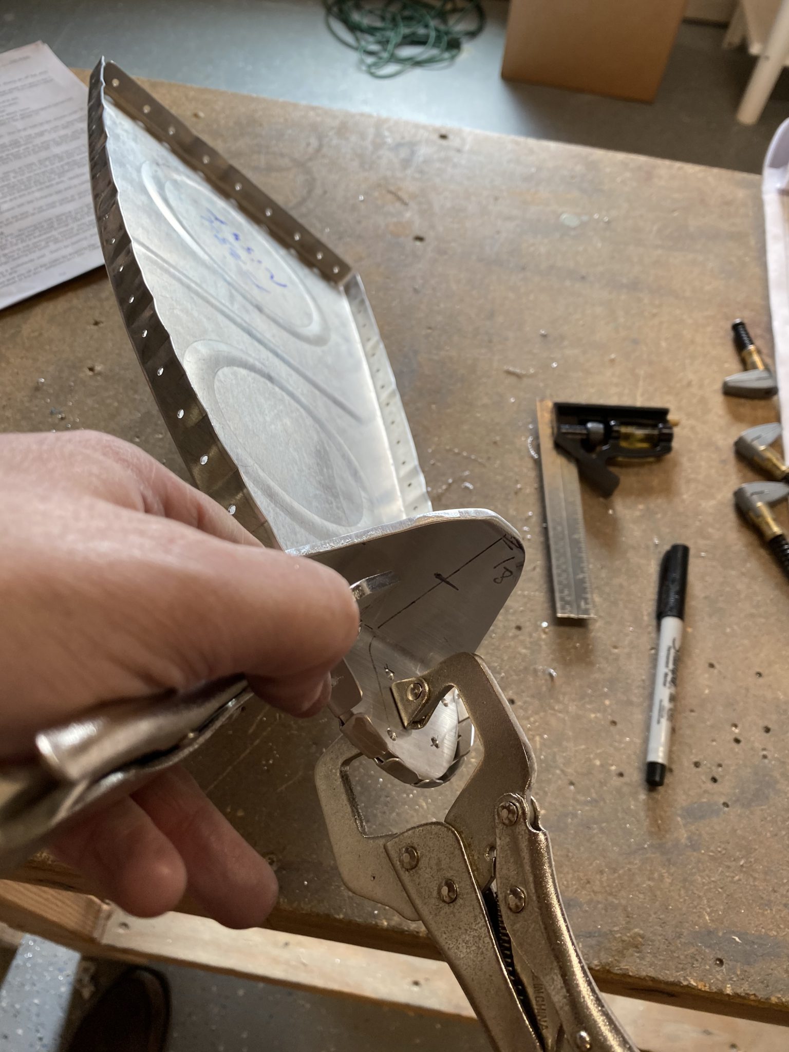
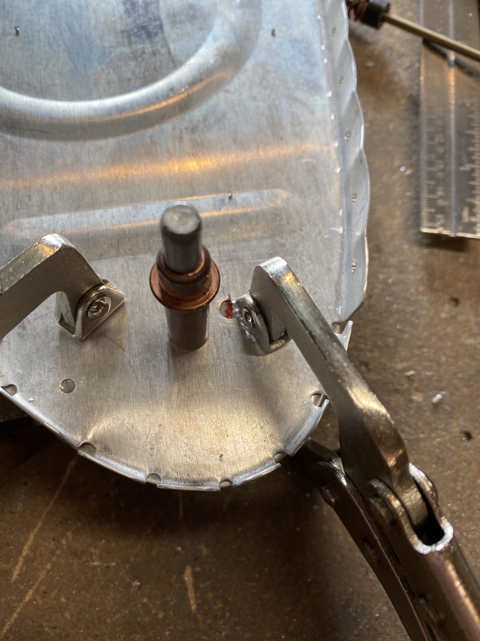
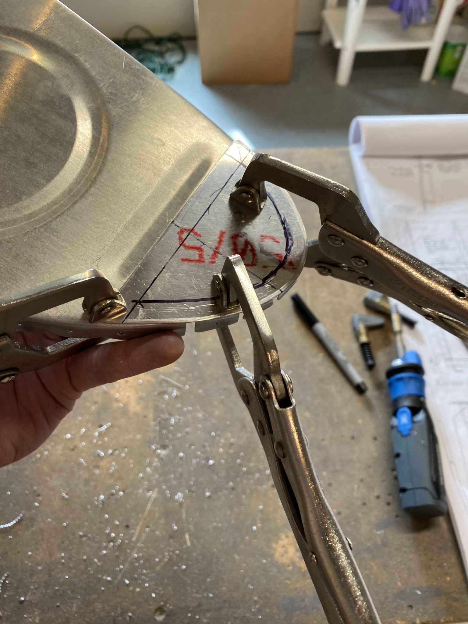
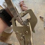
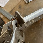
source site With the bracket lined up and clamped, I simple back drilled into the tank rib using the bracket as my template. Once I had the rib drilled, I removed the bracket and then placed the T-410 reinforcement plate on the inside of the tank rib, and lined it up. Once it was lined up where I wanted it, I clamped it down and used the newly drilled holes in the T-703-R/L tank ribs to back drill into the T-410.
https://brunobianco.com.br/parceiros/ 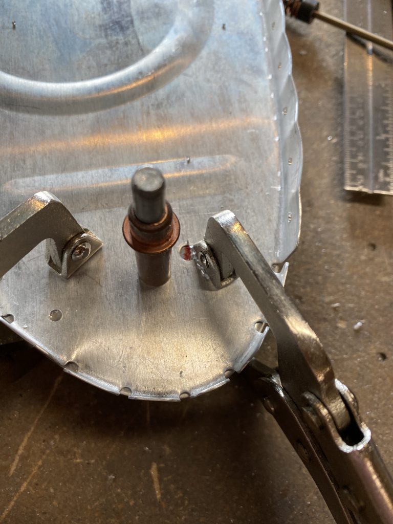
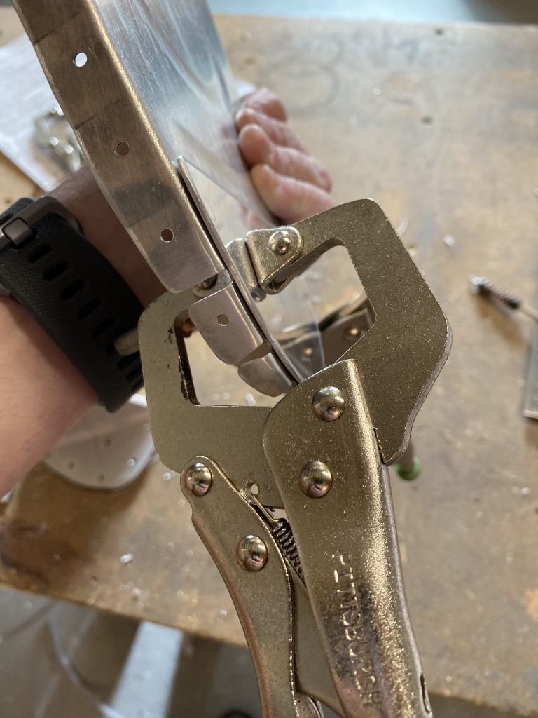
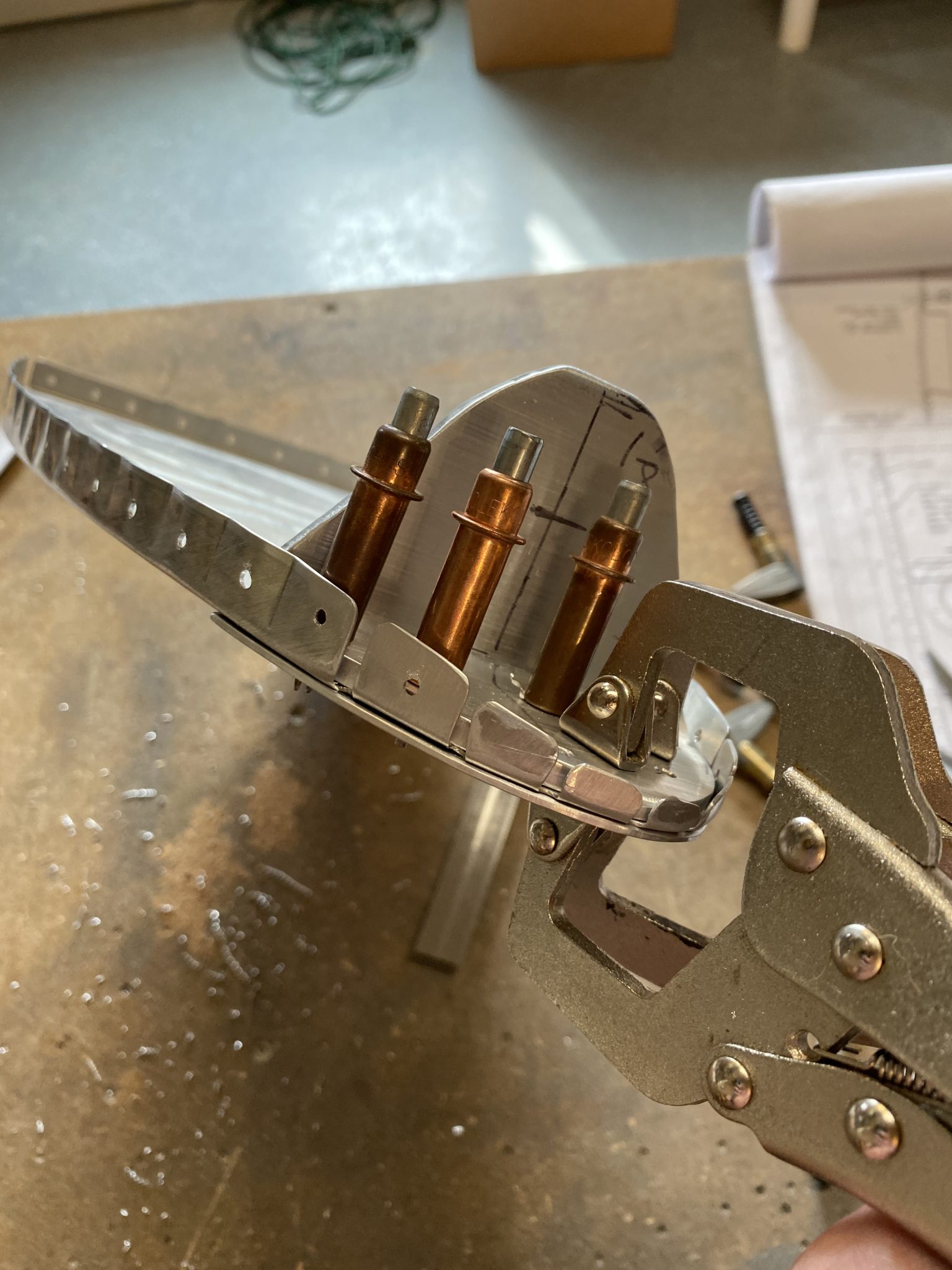
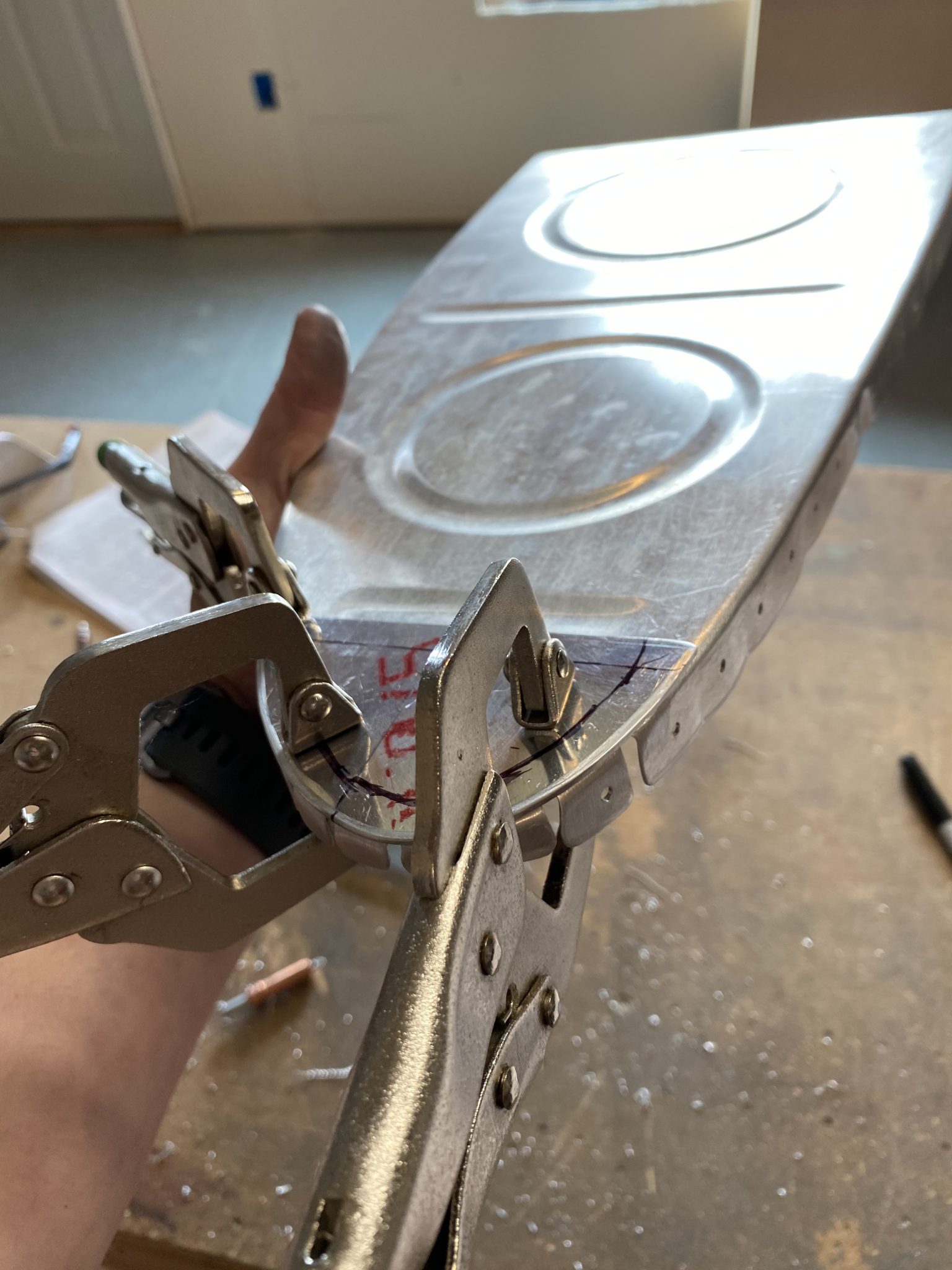
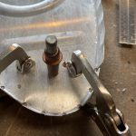
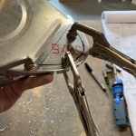
https://www.brdnug.org/about/ Now that all three parts were drilled, I clecoed everything together to make sure it all fit, and then double checked alignment. It looked pretty good, so the last thing to do was to deburr all thees new holes and then move on to the outboard rib.
see The outboard ribs were much simpler to do, since we don’t have the T-405 angle attach bracket to worry with. We simple just need to align the T-410 reinforecment plate on the leading edge of the rib, on the inside of the tank, and then choose 3 to 4 rivet holes and drill. Again, vans doesn’t give much guidance here, so I simply measured for edge distance, gave myself another 1/16″ for a buffer and then tried to space the rivets out in a decent pattern, then drilled the holes through both parts while they were clamped.
https://www.ontheballwalkies.com/contact/ 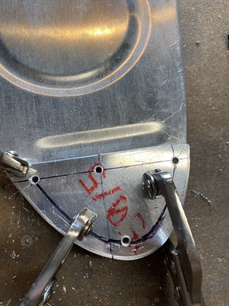
https://timlarison.com/archetypes-book-review/ Once the outboard side was drilled, I removed everything and deburred the holes. I think I did the left tank first, but after I had one tank done, it was time to move on and do the opposite side in the exact same manner. Like always, the second time goes much faster, and I didn’t take any photos of it, since its the same as the other side. Time for a quick break for a bite to eat, and then I’ll do another session tonight. Probably either the capacitve senders, or the flop tube. These are the fun parts of the build!
Ambien No Prescription Google Photos Link: https://photos.app.goo.gl/WkDGgx4wffPUXRXM7
https://destinylootcave.com/about/ Hours Worked: 2.0


