Disassembling Horizontal Stab for Priming

Tonight I started disassembling the horizontal stabilizers to prepare them for priming. This the last step in the “Drilling the horizontal stabilizer” section of the plans.

I started by unclecoing the skin from the right stabilizer, and marking it and all the parts of the skeleton as I removed them. Noting their orientation and layout. Once I had the right side done, I did the same on the left, and kept all their respective parts in separate stacks on my parts shelves.

After they were all took apart, I finished drilling the HS-710, HS-714 and HS-00001 parts per the instructions. I needed to drill the last few holes on the bent part of the spar bars to match the HS-702 and HS-00001 doubler. This only took a few minutes to complete, since it was only a few holes. However, I do have a question about some of the extra holes in the HS-00001 that I am going to ask the forum about, and possibly Vans.

Next, I started on the left stabilizer skeleton parts but deburring the holes and finishing the edges. I also took care of the edges of the lightning holes. I didn’t get all of the parts done for the left stabilizer, but I got a good majority of them. I’ll leave the rest for another day. Once I have them all deburred and the edges smoothed, I will dimple the ones needing flush rivets and then get ready to paint them all (hopefully this weekend).


Here’s the photos of tonight’s work: https://goo.gl/photos/6vPJvvS4wQvg26Ym6

Hours Worked: 3

Drilling Right Horizontal Stabilizer

Today I worked on the right horizontal stabilizer. Technically I completed the “Drilling the horizontal stabilizer” section of the plans, save for the riveting.

Todays session was pretty much identical to the last one, except I was completing the right side horizontal stabilizer as opposed to the left from the previous session.

In summary, I clecoed the ribs, then match drilled them to form the skeleton. Then I worked on fitting the HS-00005 and HS-00006 ribs into the skeleton and marking, and back drilling them. The tedious part was the measuring and aligning, and then clamping everything to drill.

Once they were good to go, I started back and match drilling the skins to the ribs and spars. That wrapped up the session for the night. To finish out this subsection, I will disassemble both sides so that I can prep them for priming and riveting.

Thats going to include:
1. Deburring all the holes
2. Scotchbrite all the edges
3. Rounding any corners
4. Scuffing the surfaces
5. Cleaning everything with acetone.
6. Spraying Akzo
7. Dimpling the skins and ribs
8 Riveting everything together.


Heres the photos from tonights work: https://goo.gl/photos/5XakAzTRj4FCnpic7

Hours Worked: 3.5

Drilling the Horizontal Stabilizer

Today was a good day on the project, with lots of progress being made, and ultimately a flying surface assembled. Tonights work began with going back a few steps in the plans to assemble the HS-00001 doubler plate to the front spar. I measured out where the edges should be per the plans, and clamped them in place to drill their rivet holes. Once I had both sides done, I marked that step done in the plans and moved on.

I started the section in the plans called “Drilling the Horizontal Stabilizer”. I spent a good bit of the time today just looking over the plans and laying out the parts to get an idea of how it all should look and how I should drill out the front spar and spar doublers. Over the short break from the last session I read up SB for the front spar to learn how it should be assembled and drilled. It wasn’t as bad as I thought.

I picked out which ribs would be left and right, and marked them. Then I marked the centerlines using the dimensions from the plans for HS-00005 and HS-00006. I finally got to use the Noxon center punch to mark my drill location for HS-00006 and drilled the holes in the front flange.

Starting with the left horizontal stabilizer, I clecoed all the ribs and spars together to form the skeleton. Then I match drilled to #30 all of the holes attaching the ribs to the spars, except for where it attaches to HS-609pp. I left that hole untouched for now per the plans, until later on then drilled it to size#21. The un-clecod everything to clean out the drill chips. The pneumatic cleco tool make this work easy.

After re-assembling the left skeleton, I had my wife help me get the HS-601PP skin clecod to the skeleton. This took some finesse. Due to the gradual taper on the leading edge, we had to very gently flex the skin to fit around the nose ribs without bending them. After a few attempts, we managed to get the skin clecod down and looking like an airplane part!

Then it was time to fit, clamp and drill the HS-00005 and HS-00006 ribs. This took me a good bit of fiddling around. This started with fitting the HS-00001 doubler, and the HS-710 and HS-714 support bars to the front spar. Then I inserted the ribs and worked to get them lined up perfectly with the edge of the skins. These parts are not pre-punched so I marked a centerline across all the flanges just to make sure I lined them up to maintain edge distance on the skins holes. I used the front rib holes to back drill the front spar after I had it lined up with the skin, and then removed it so I could insert the rear rib (HS-00005) and line up the centerline mark through the holes I just drilled, then back drill it. After all the aligning and clamping and measuring, I ended up with the front and rear ribs completely flush against the edge of the skin, with the centerlines lined up on the skins holes. After everything was clamped and held securely in place, I began back drilling the HS-00005 rib using the holes in the skin, and then followed up with the HS-00006 rib in the same manner.

The last step was match and back drilling the skin to the spars and ribs using a #30. I clecoed every hole along the curves of the ribs and just removed the cleco to drill its hole then reinserted it to prevent the rib from shifting. After it was all done, I came out with a fully assembled left horizontal stabilizer! This was a good stopping point for the night, and I will work on the right one the next session. I predict it won’t take as long since I am familiar with the process now.


Photos from todays work: https://goo.gl/photos/Bz4bwuyfd8rZLcFv5

Hours Worked: 6

Front Spar Complete

After reading over the plans and instructions last night I decided to get to work today with a clear mind. I completed the Front Spar Assembly section of the empennage section with the exception of deburring, dimpling and priming. I am going to combine as many of the parts as I can and complete these together to save setup time in my priming booth. There is no riveting to be done at this point anyways, so it will work out perfectly.

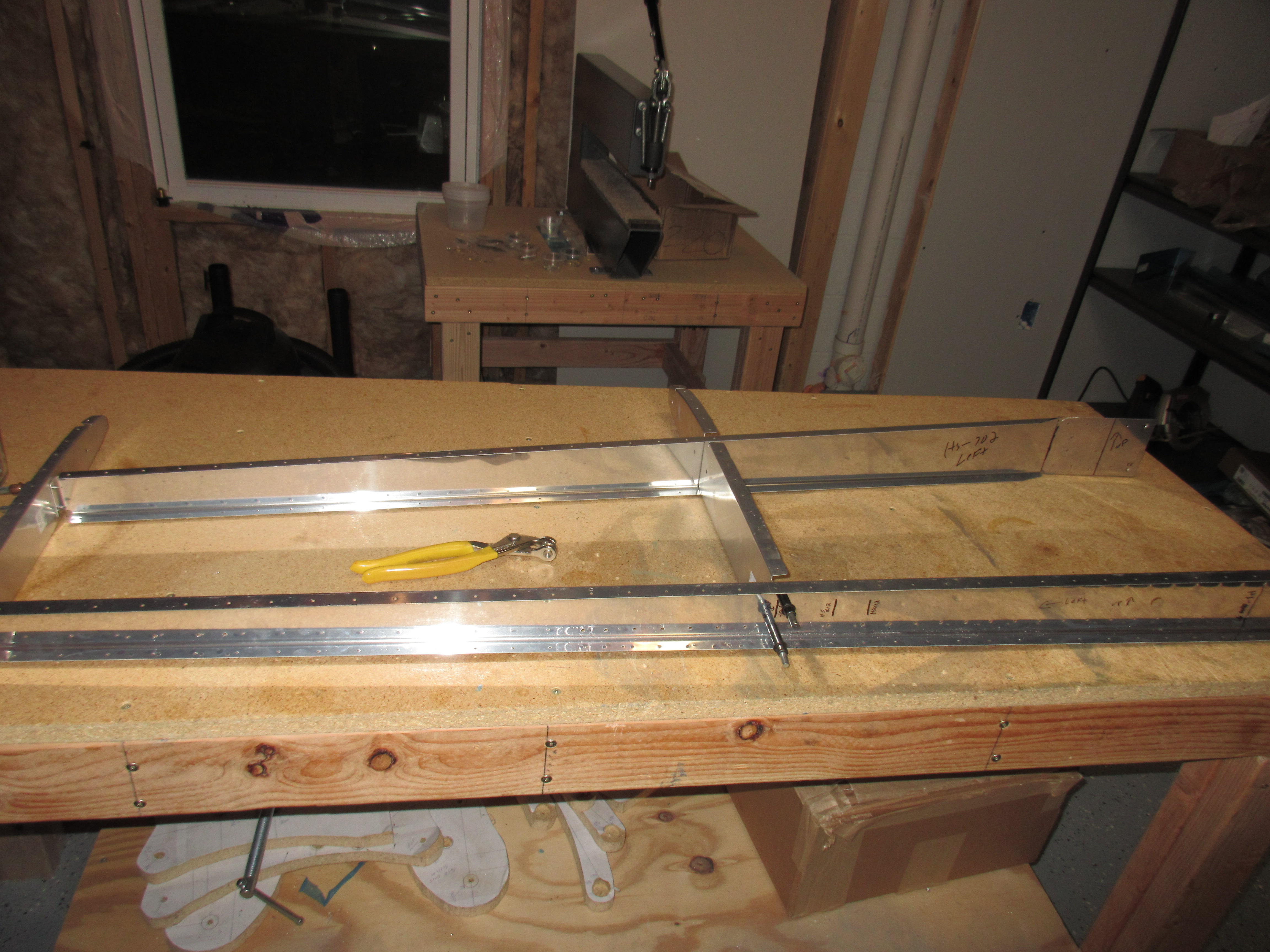
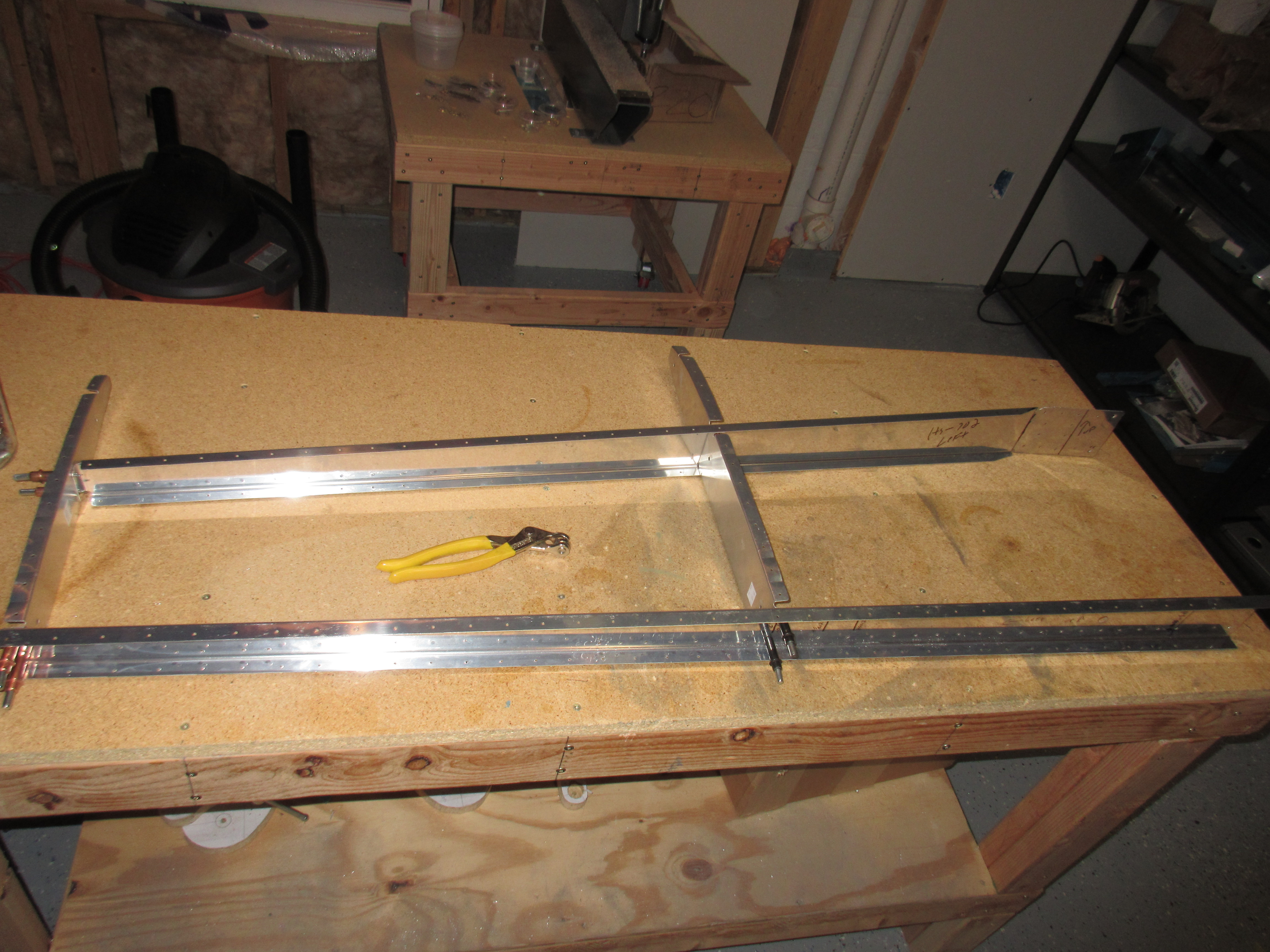
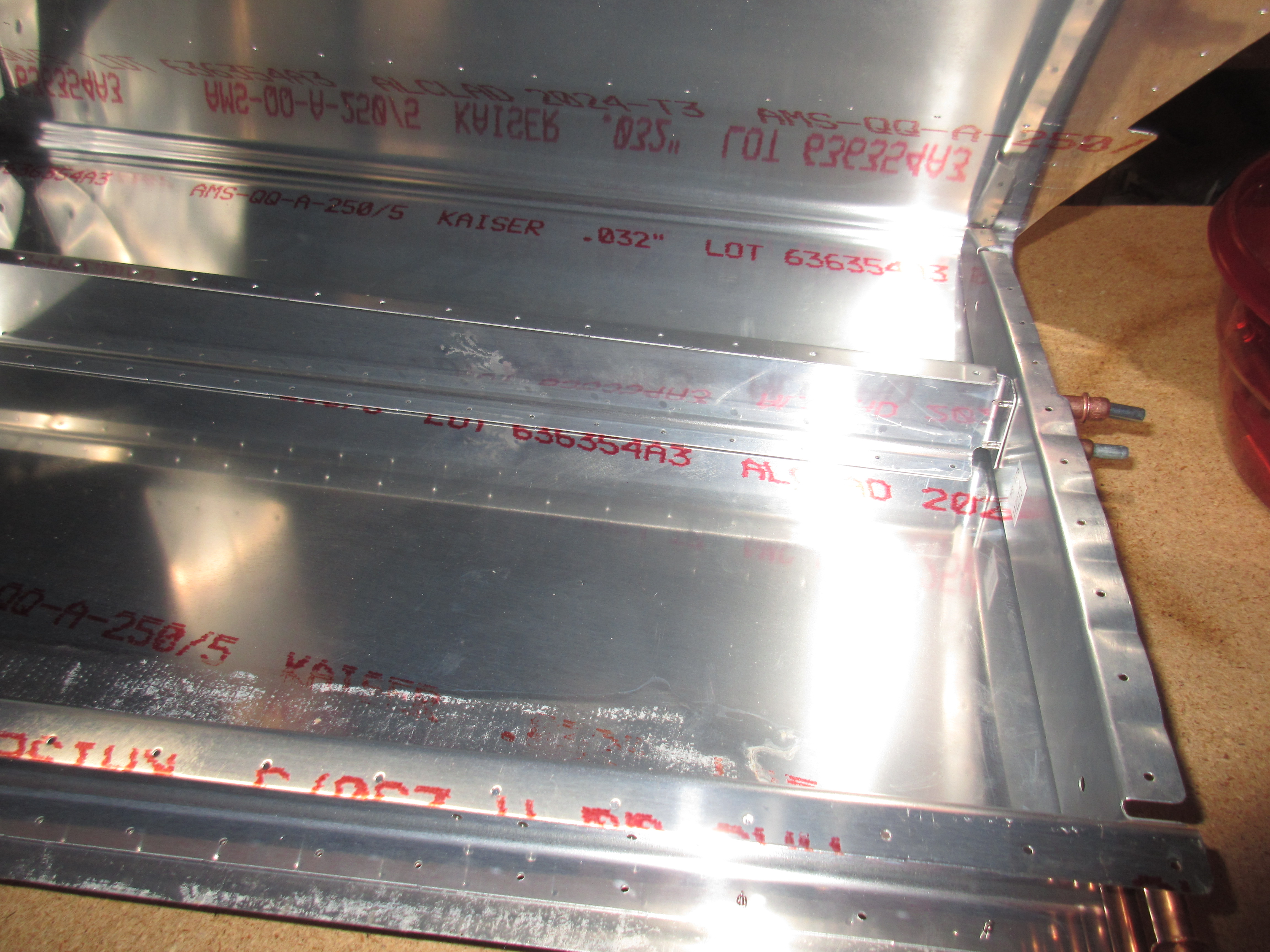
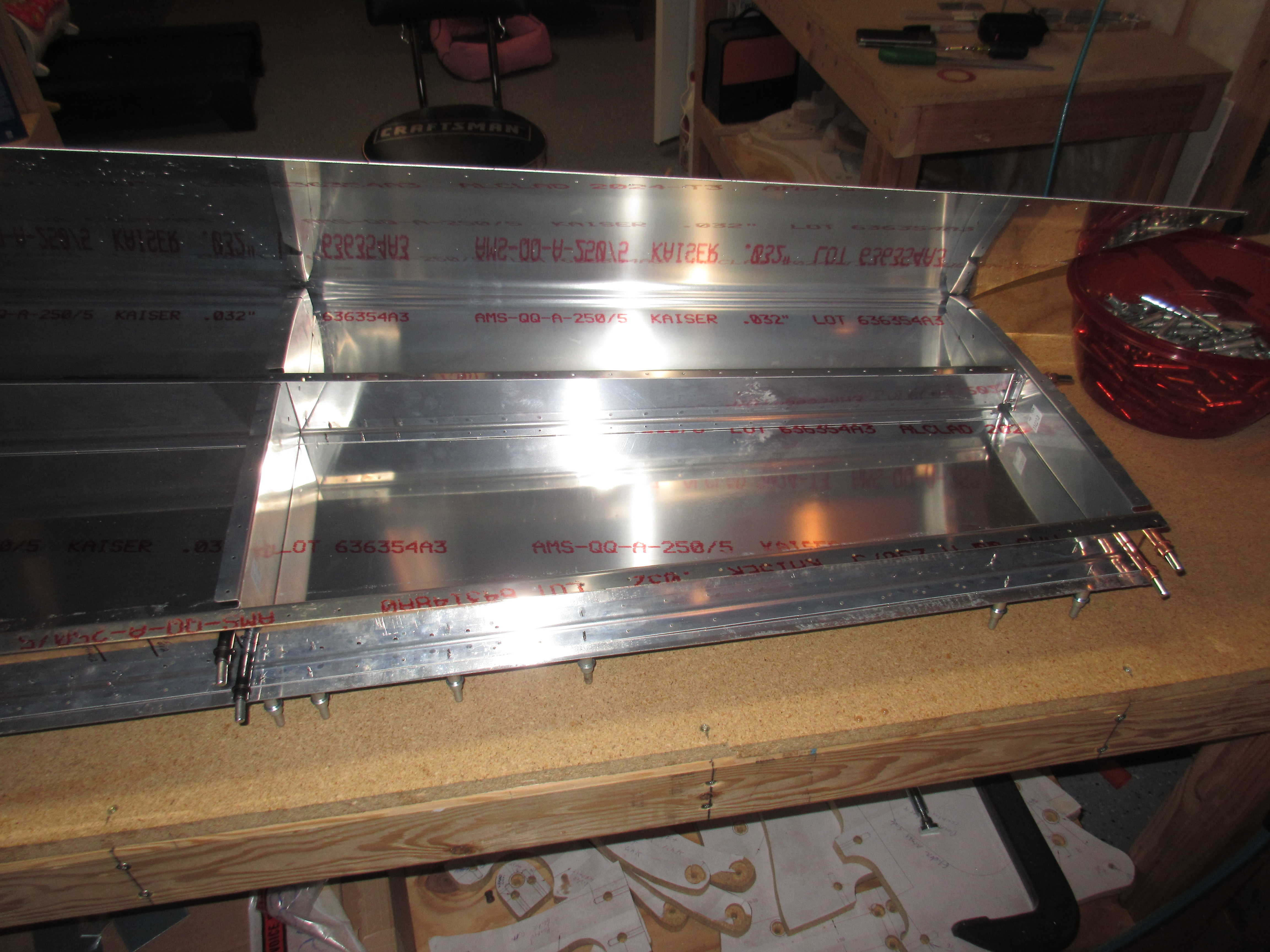
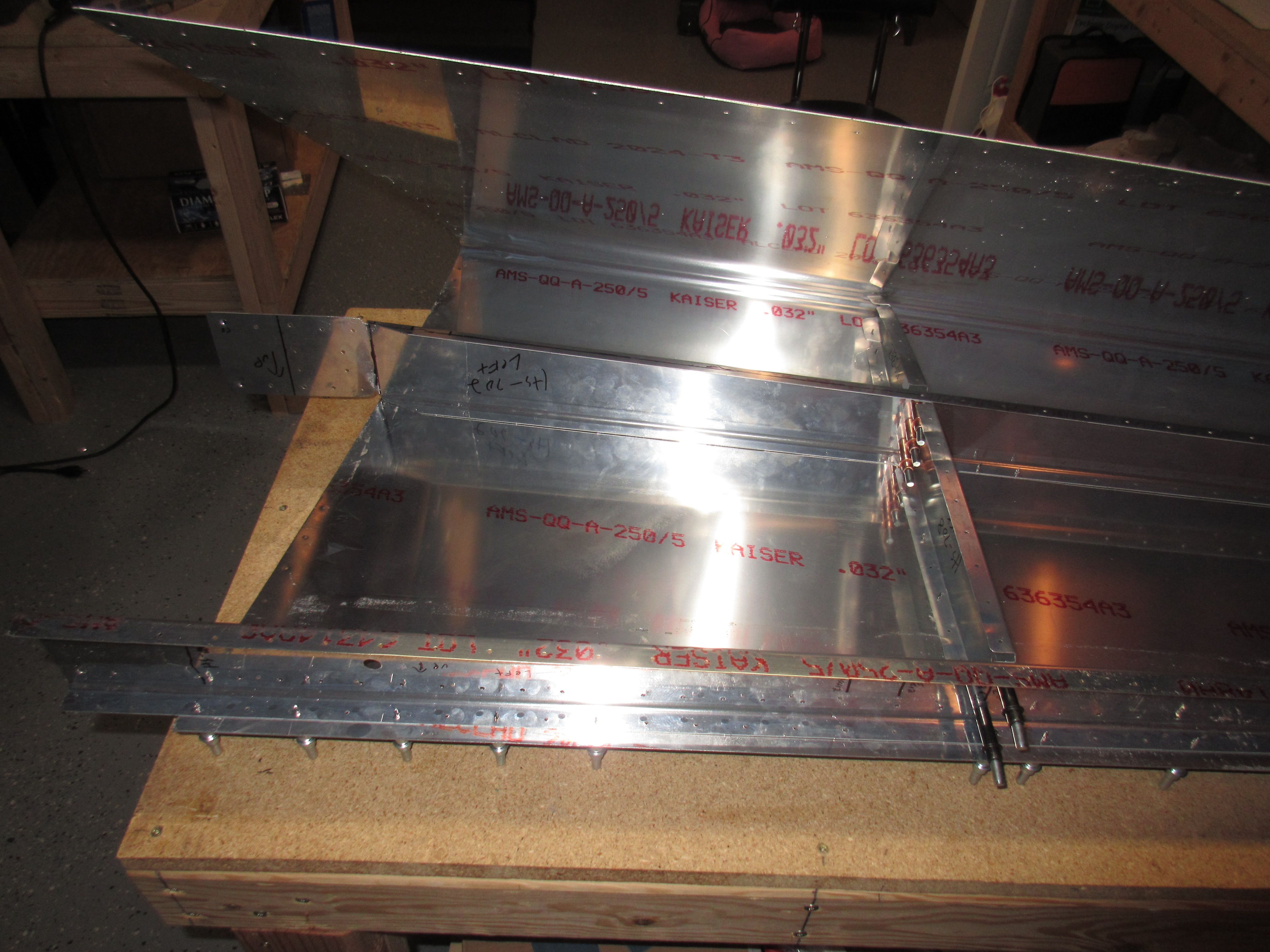
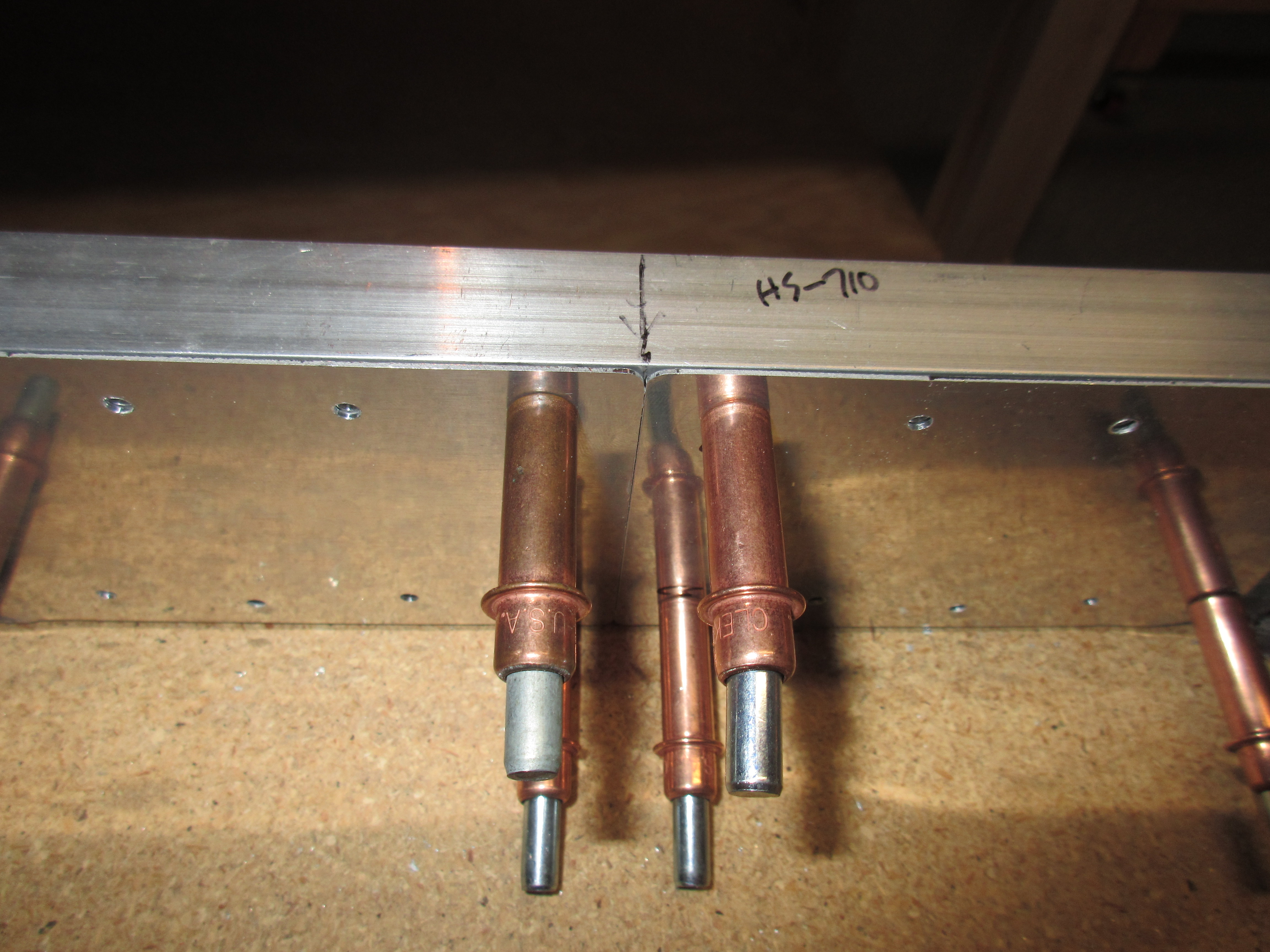
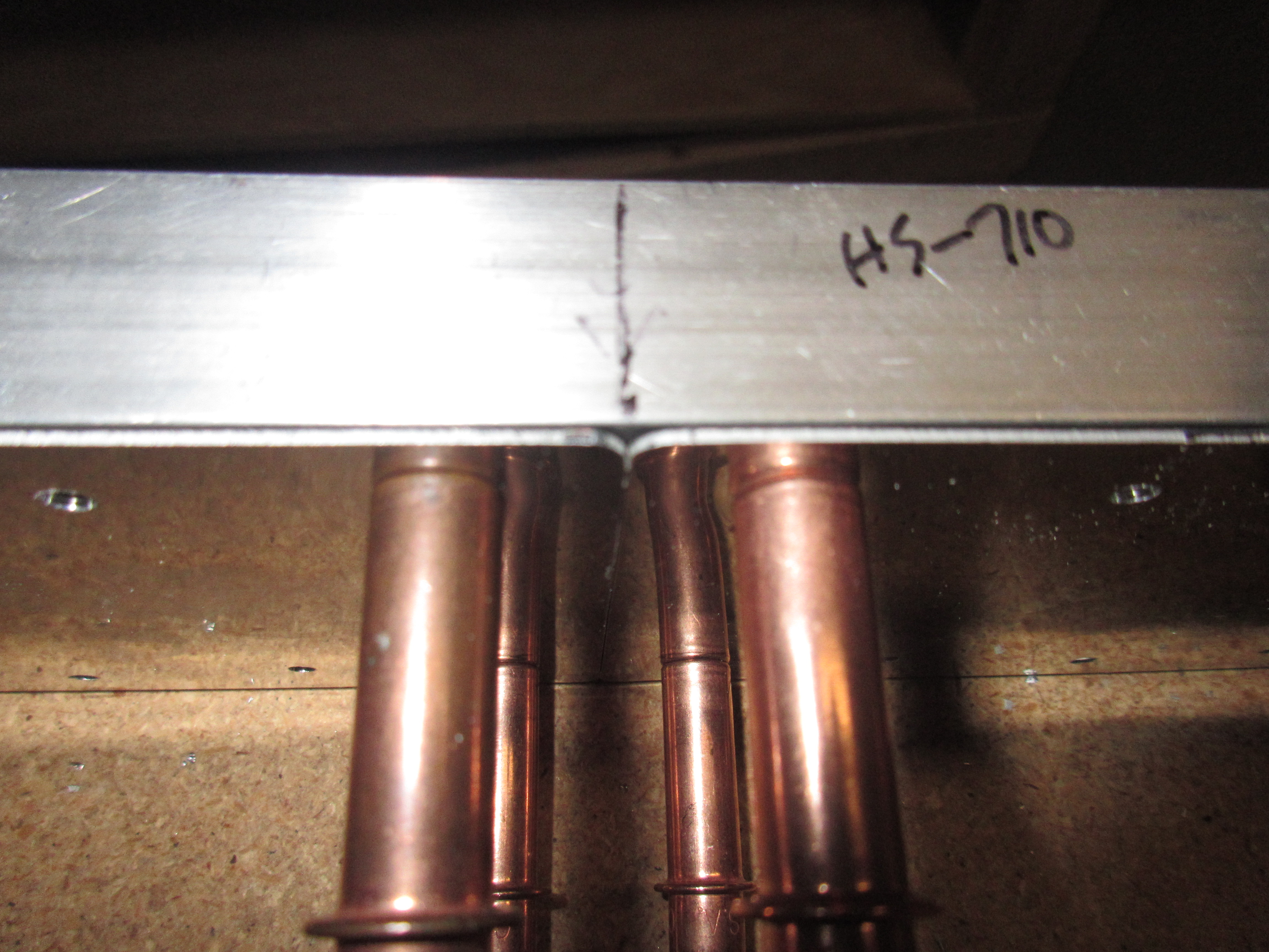
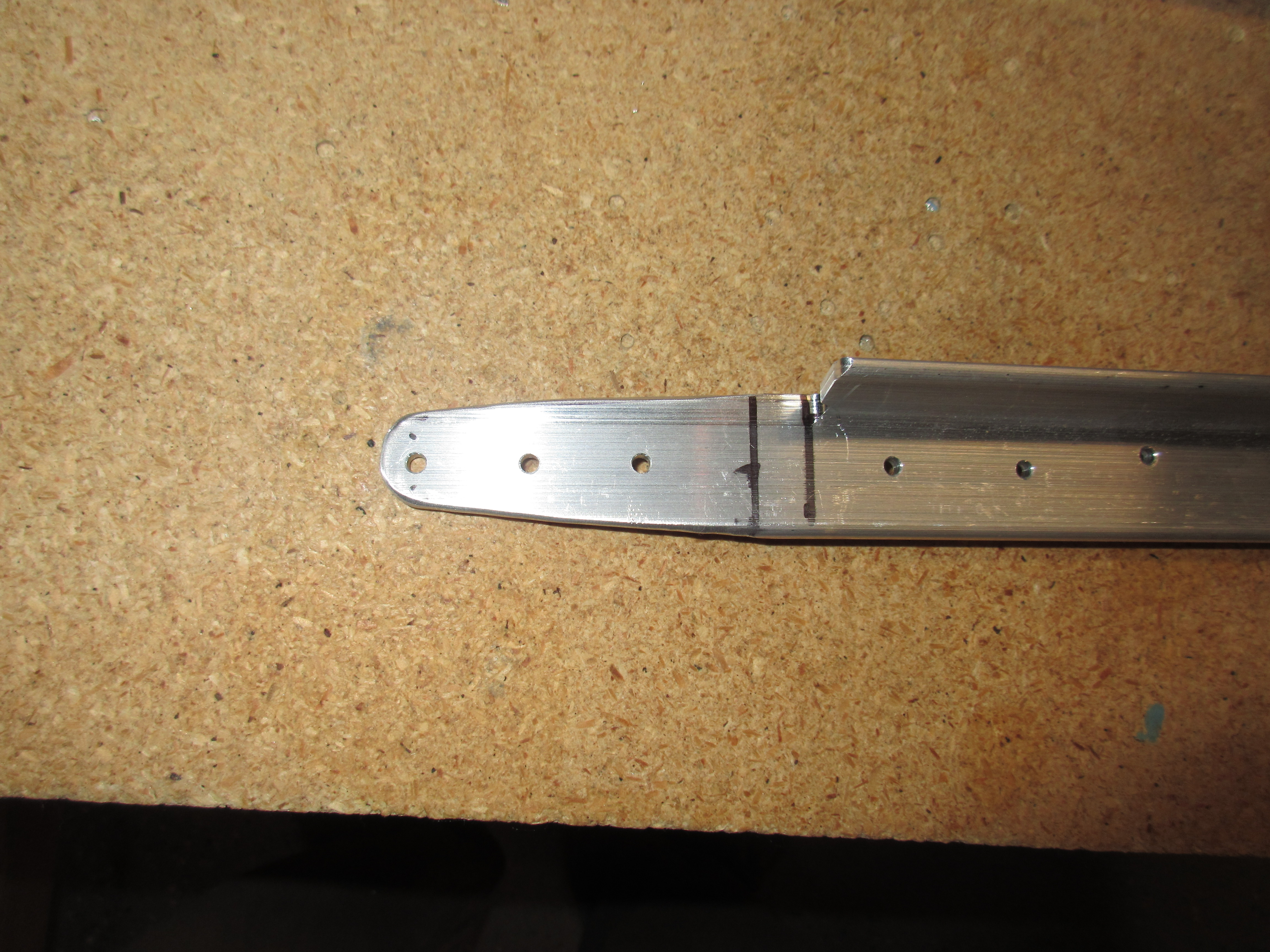
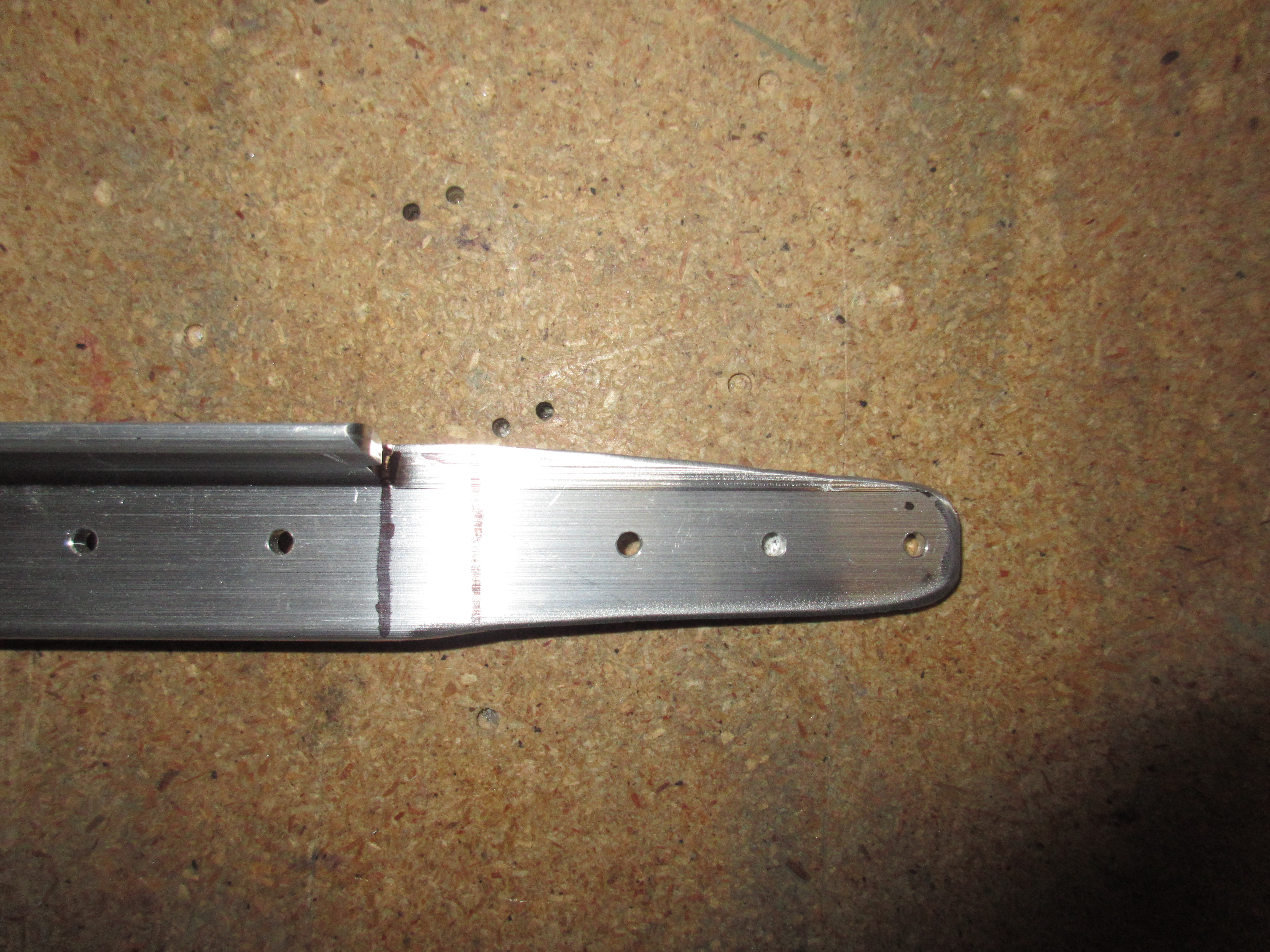
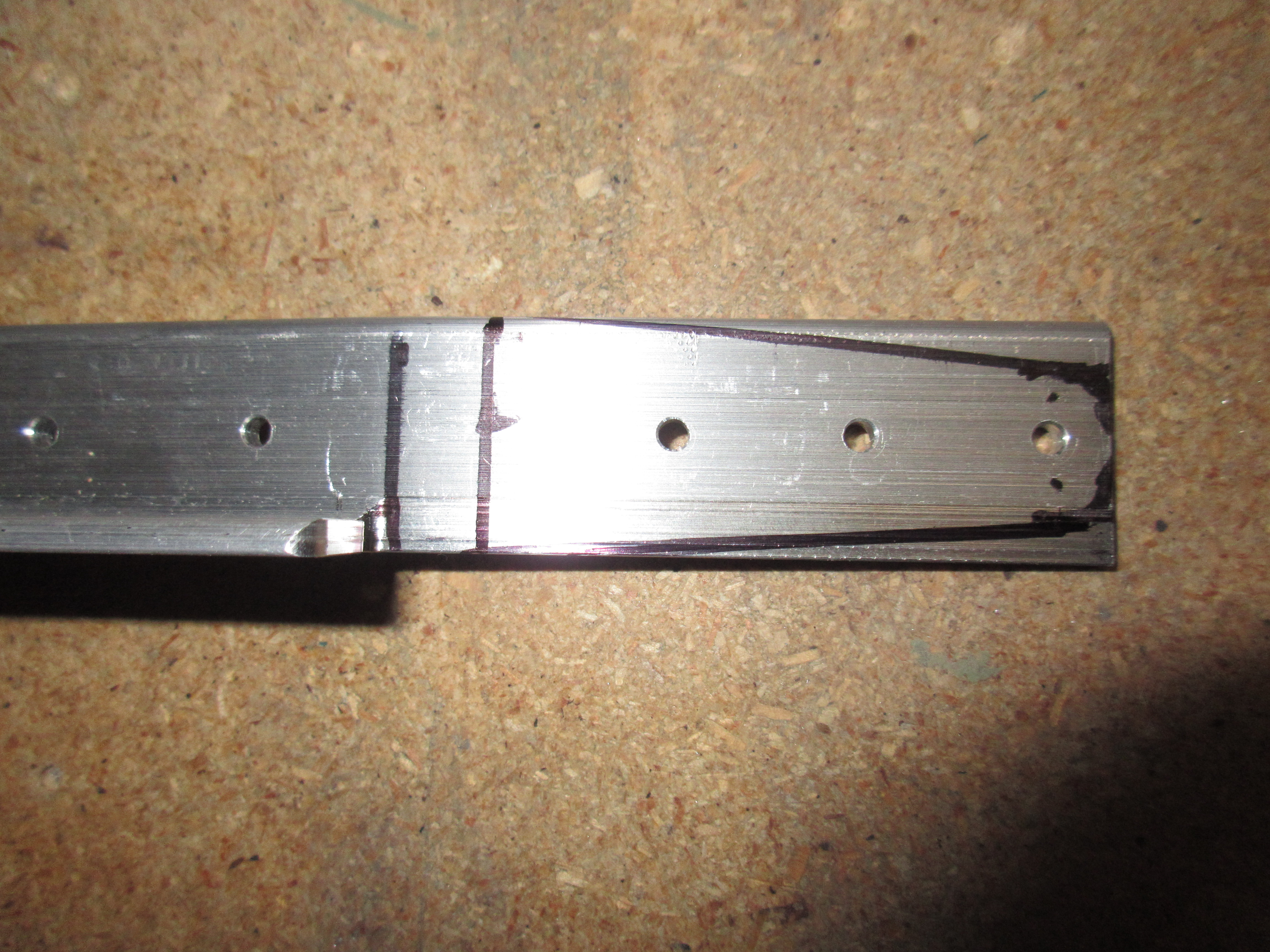
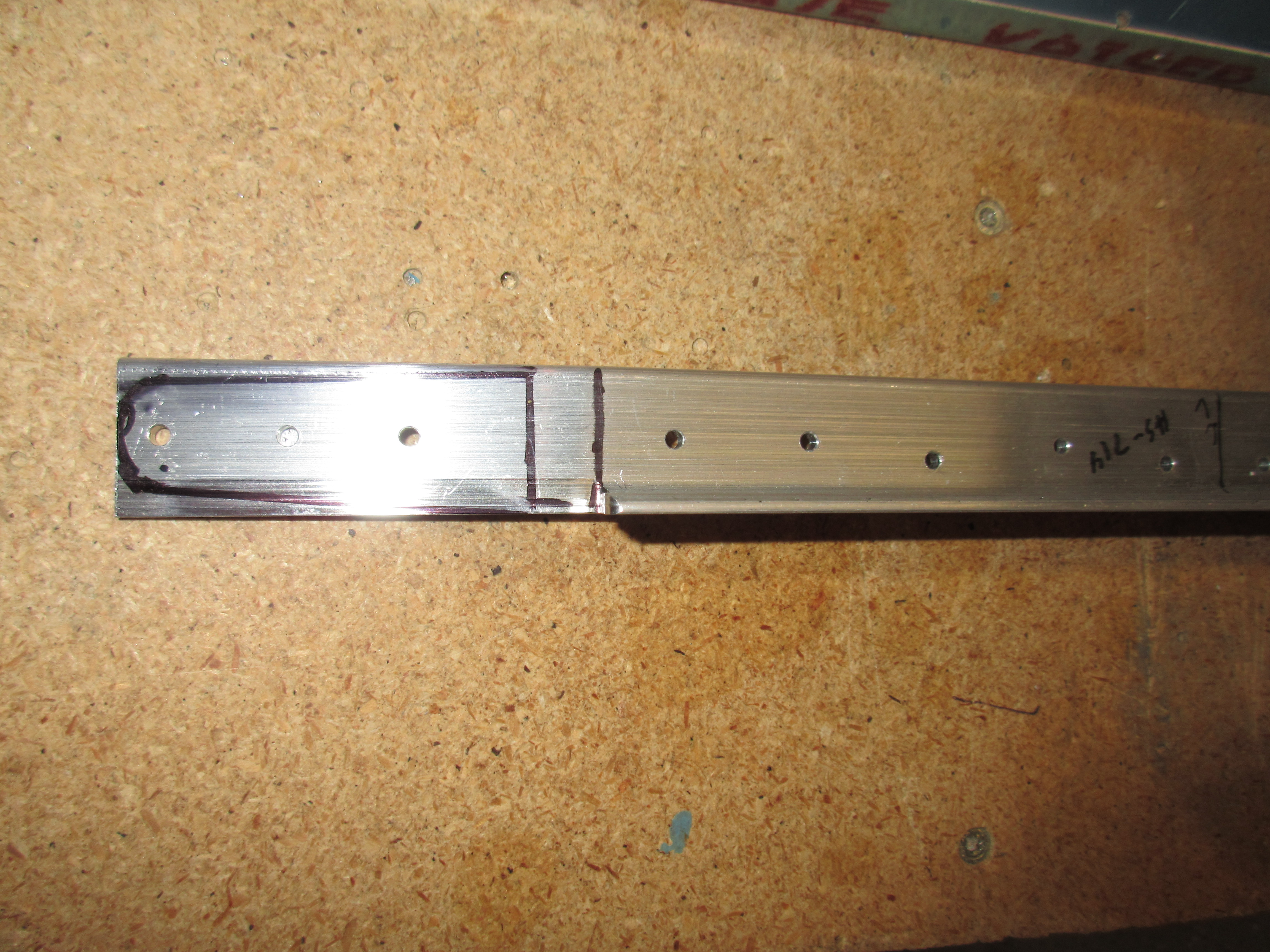
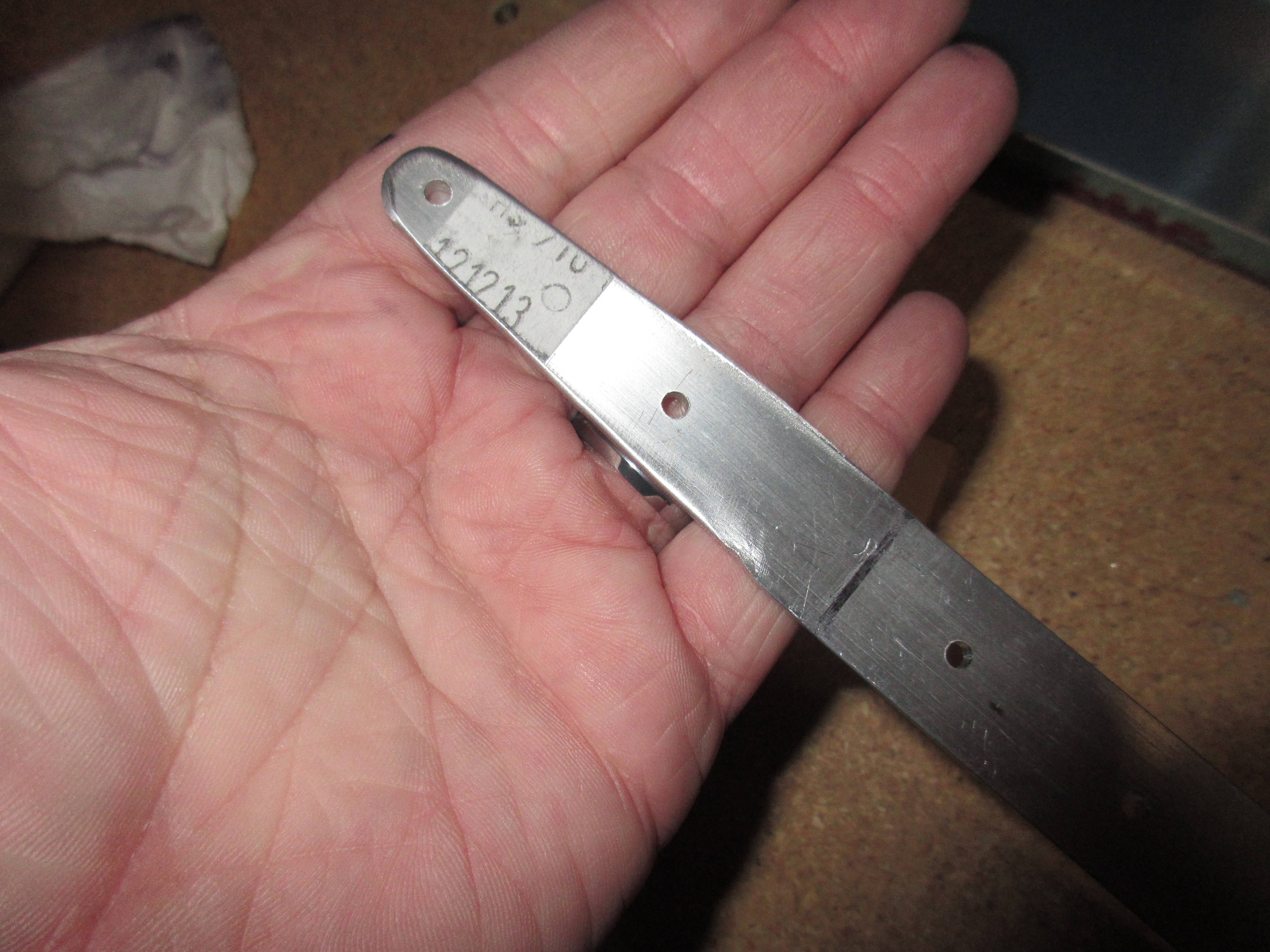
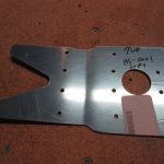
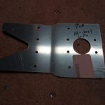
I cleco’d HS-710 and HS714 to the HS-702 spar channels and marked the lines for center line and the bend lines per the plans. Then it was time to do a little fabricating on the spar channel. I cut off the flanges of the spar channel inboard of the bend lines and smoothed the edges. Then I drilled the relief holes and enlarged it to 1/4 on the channels. I only trimmed the angle back just a bit for now until I could measure and cut after the bend was made.

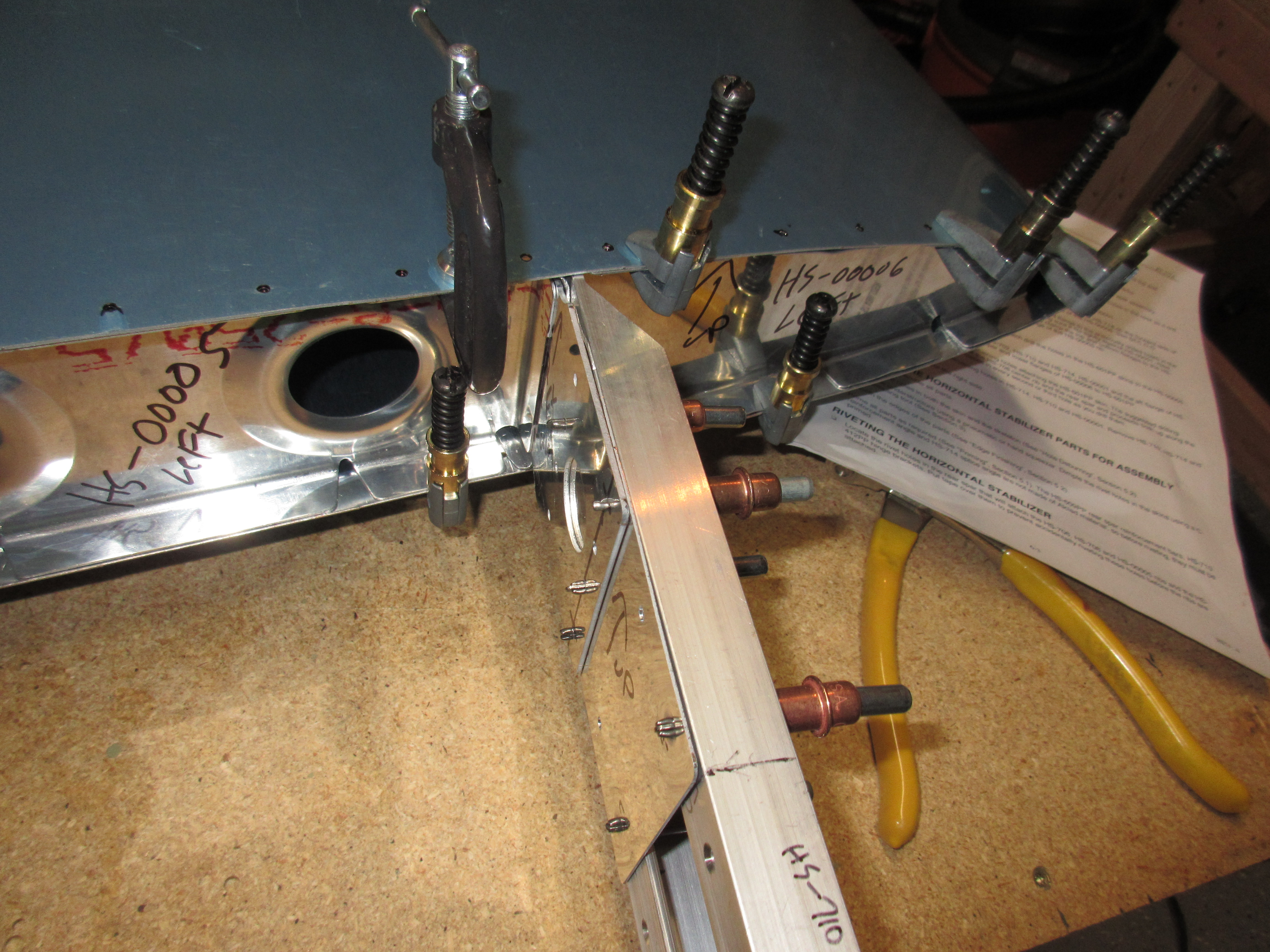
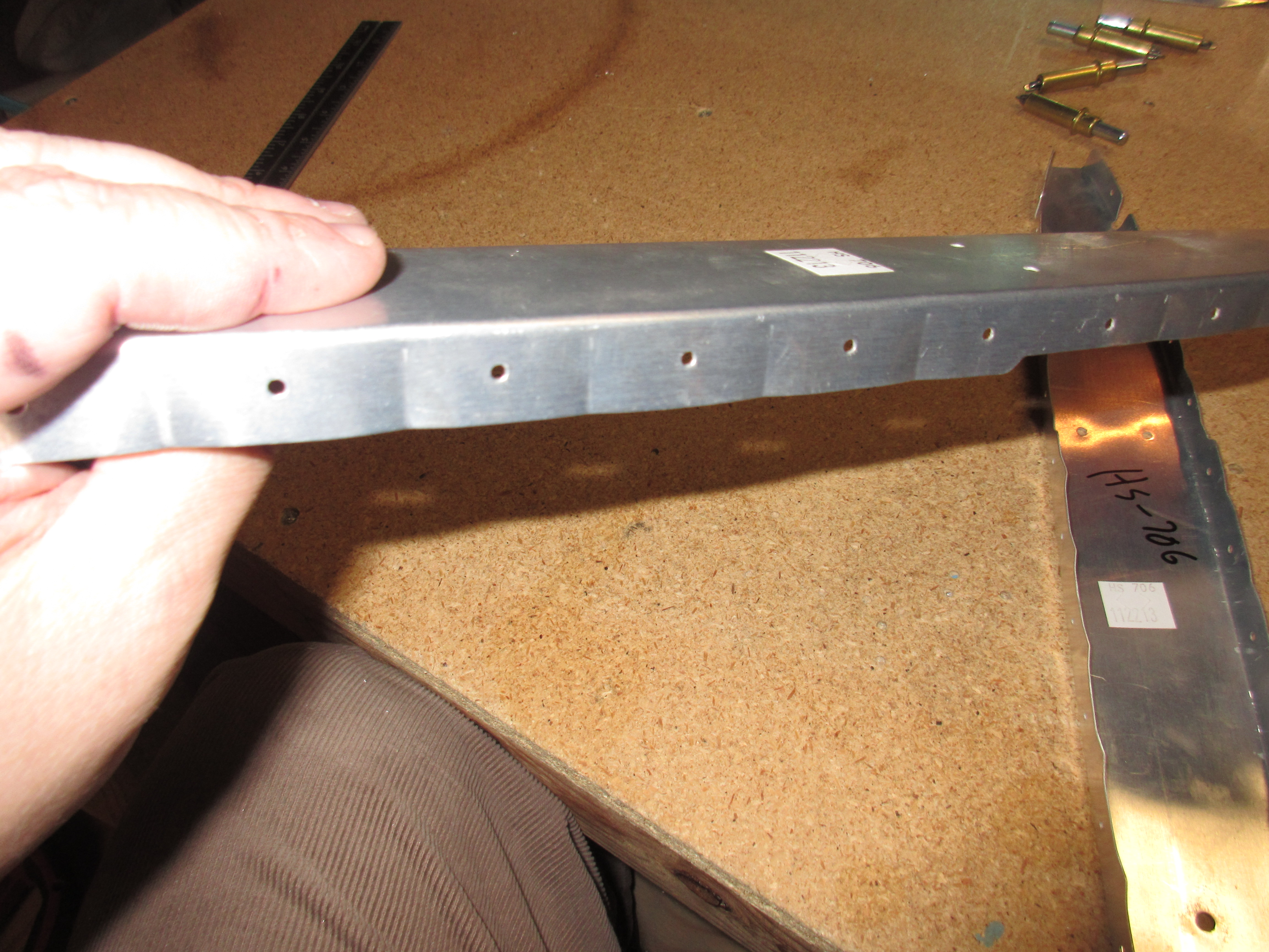
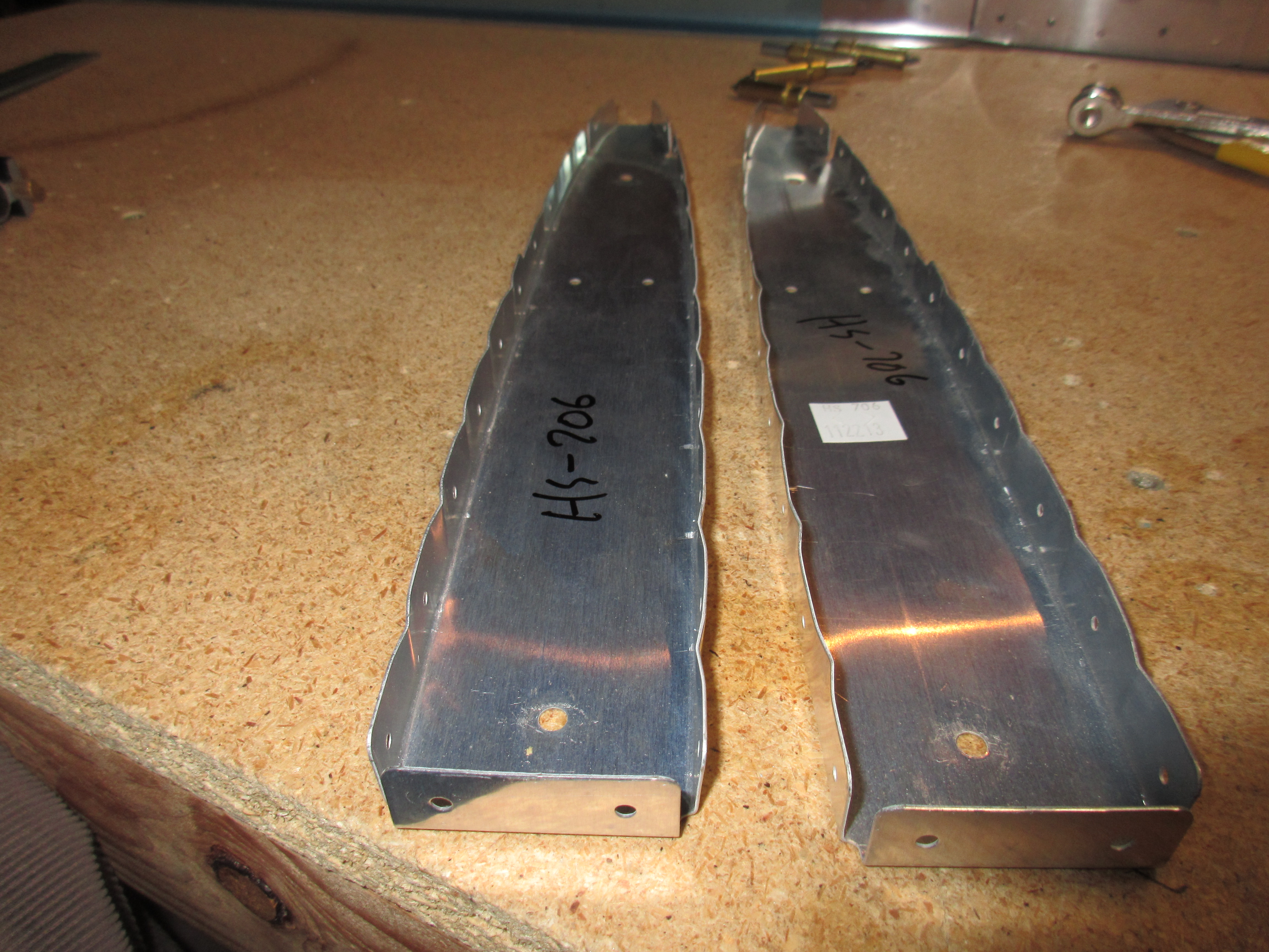
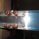
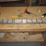
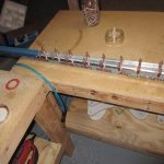
Then I bent the HS-702 spar channels to the exact 6 degrees using my hand seamer and a protractor. They turned out nicely. From there, I re-clecod the HS-710 and HS-714 so I could match drill everything inboard of the bend lines and rib attachment holes.

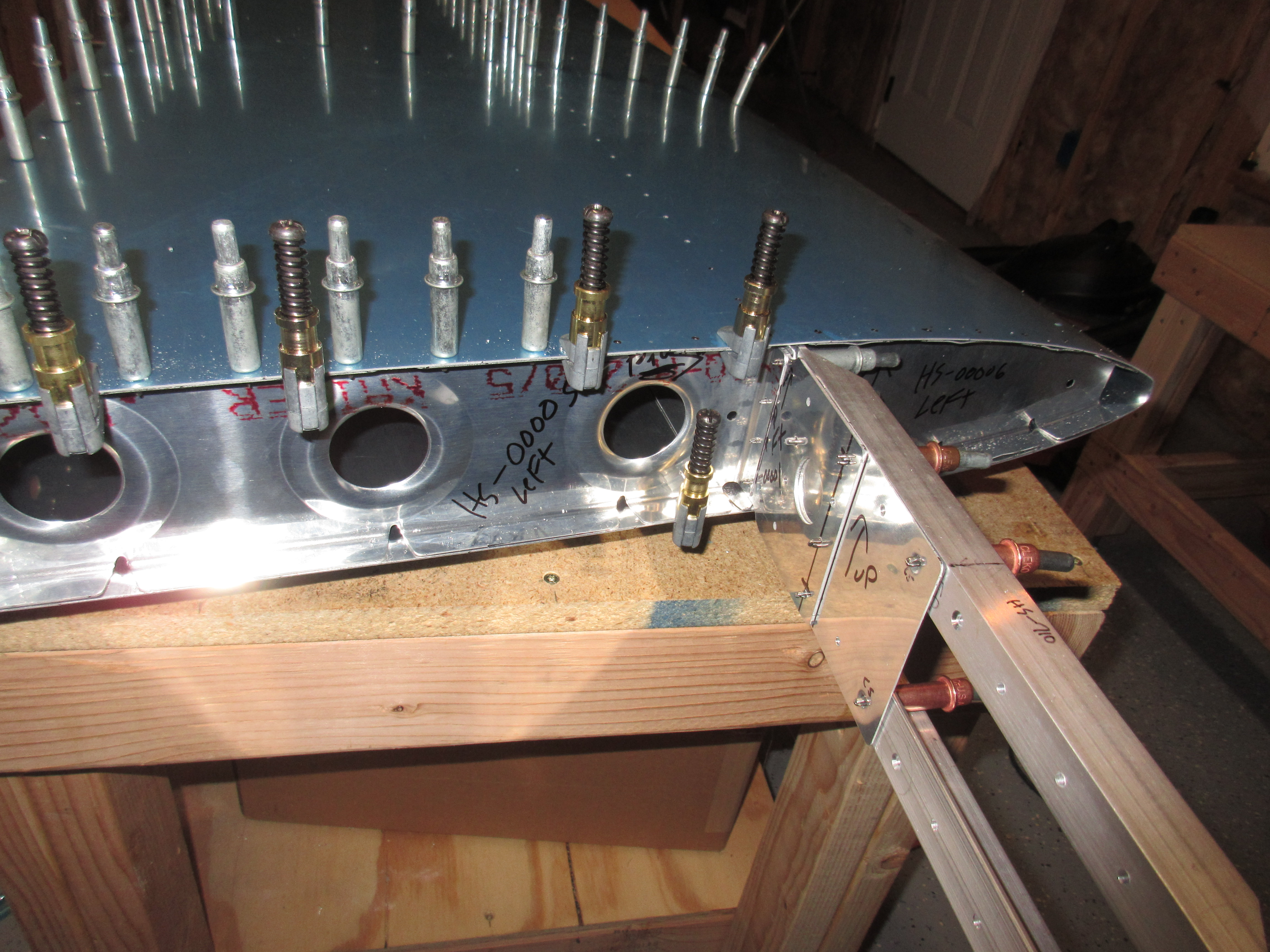
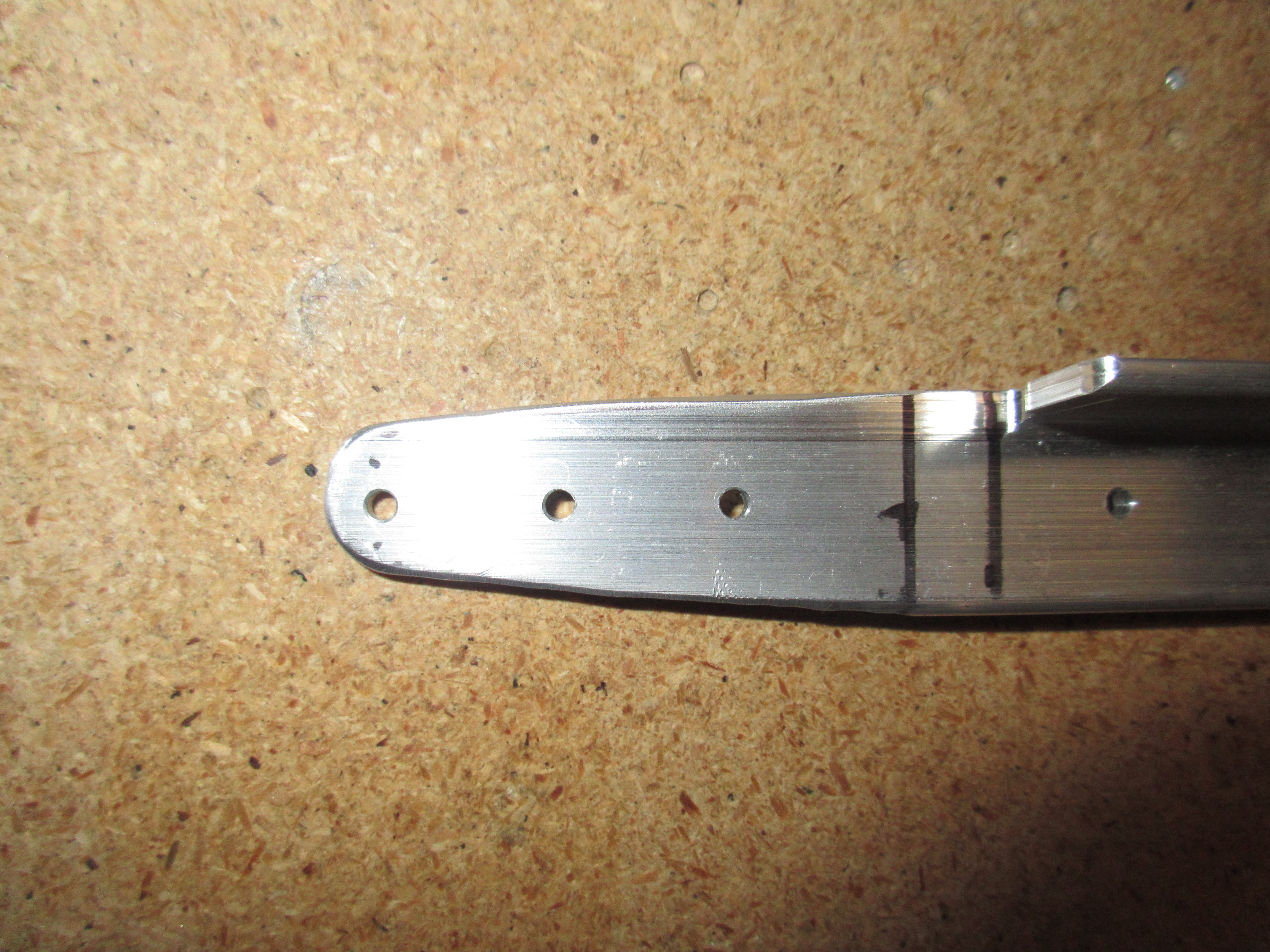
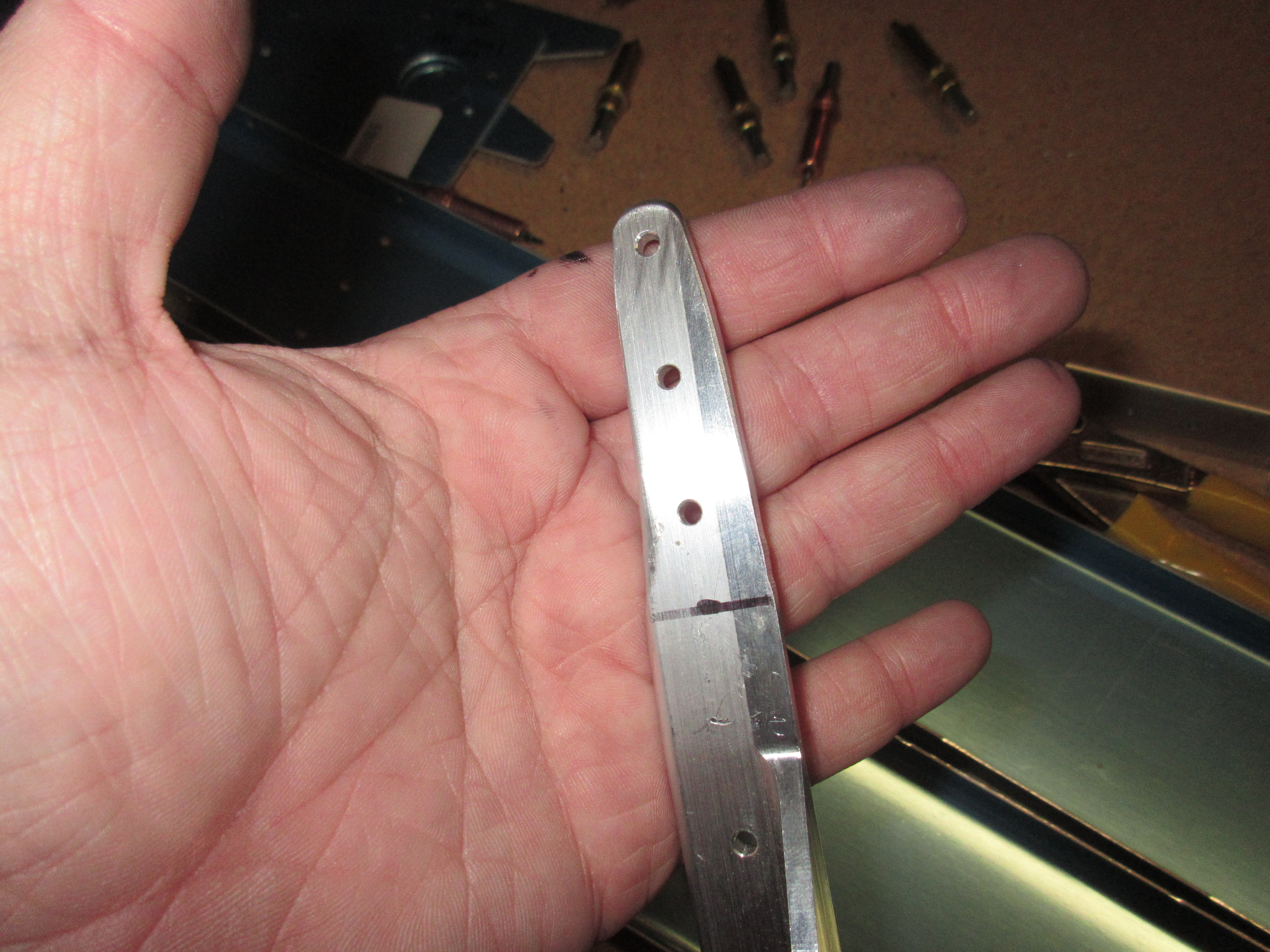
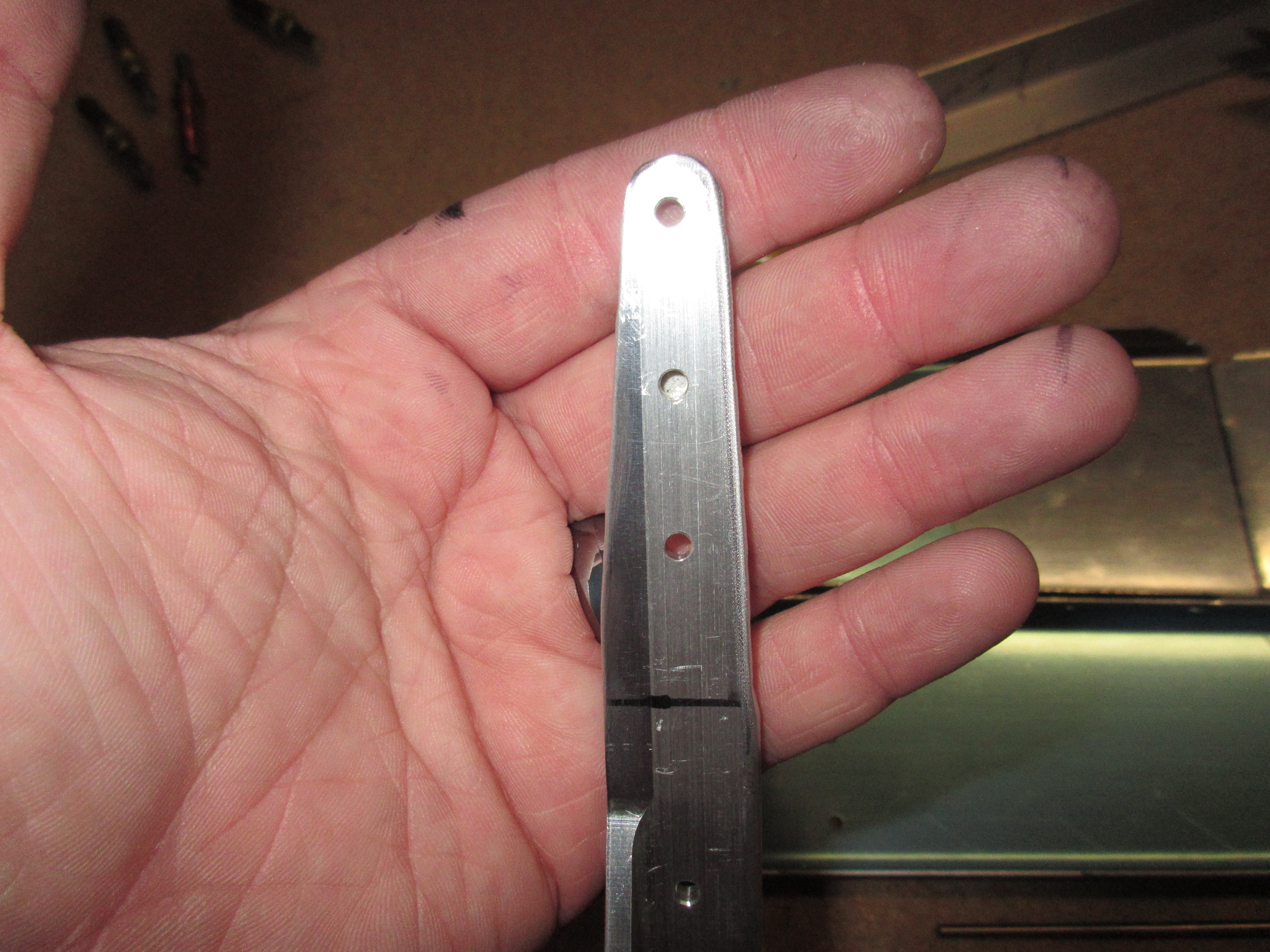
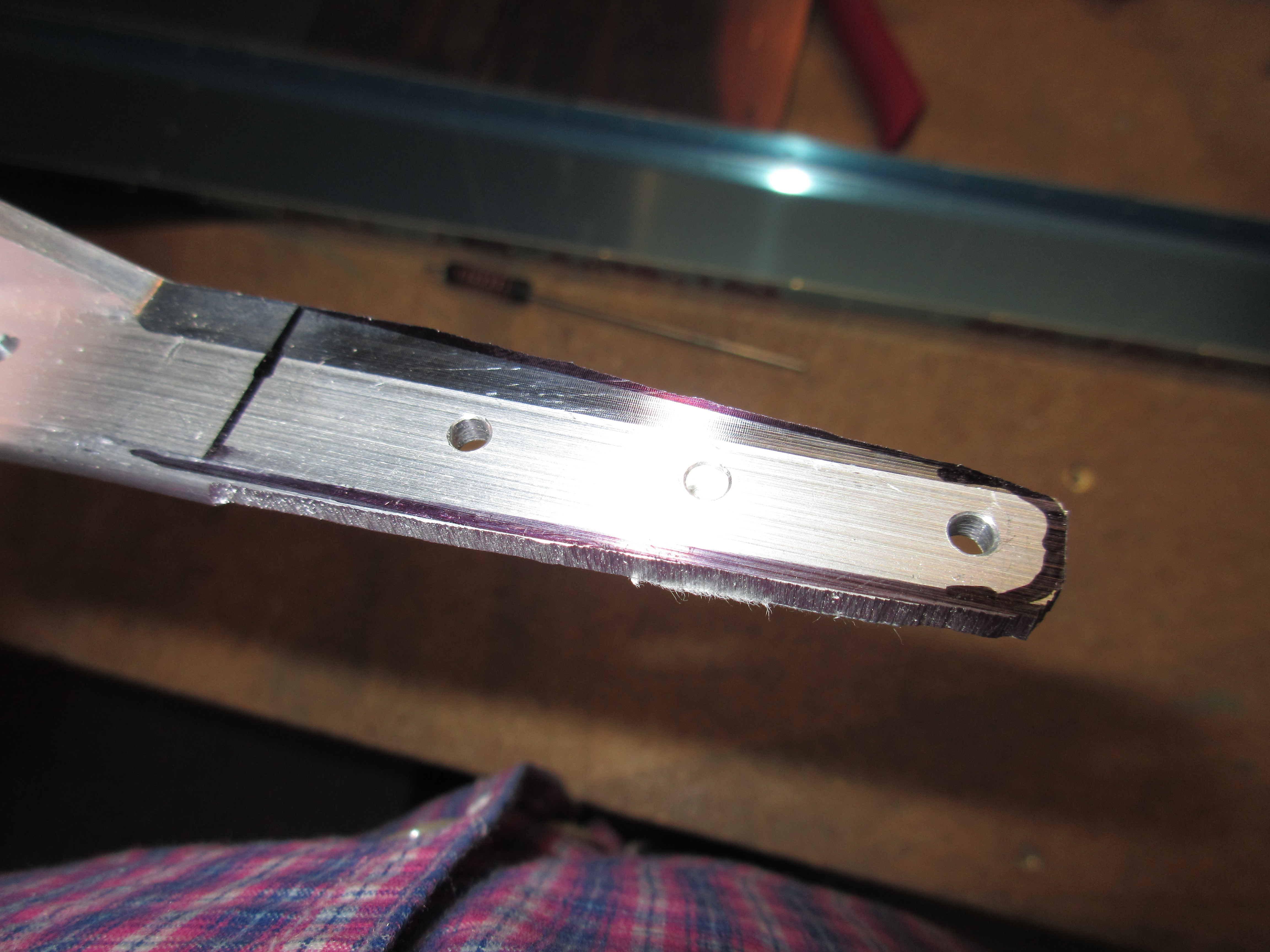
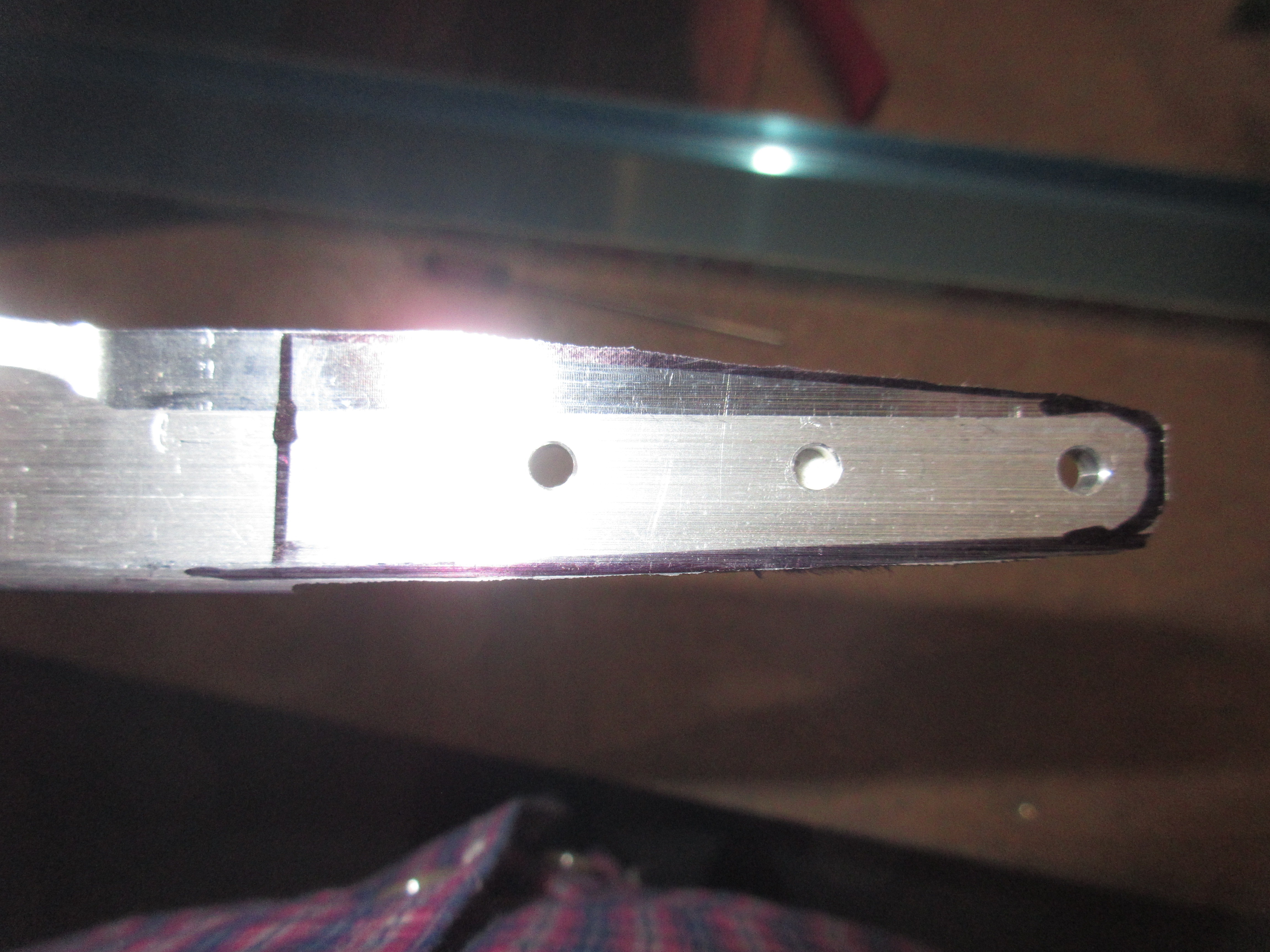
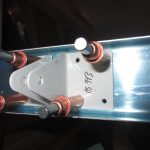
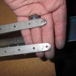
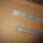
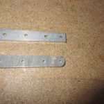
Next I tapered the ends of HS-710 and HS-714 per the detail section of the plans. I used my bench grinder on this part to make it easier. I marked the lines a bit large so I didn’t over-grind anything. Once I got a taper that I liked, I polished the edges off with the scotchbrite wheel so I wouldn’t scratch the spars or my hands. I will finish them off better once I get ready to prime everything. I left some notes in my plans to do this. After the taper was set for them, I measured for my bend lines and then bent them using a vise to the 6 degree angle per my protractor. While the tapers may not be as beautifully done as the pros, I hope they will be OK. They meet the edge distance requirements with some meat left, and they taper nicely along the spar channels and the edges are broken clean. I think thats the only requirements for this to be a safe part. I may ask the folks in the RV-7 sub just to make sure, since I can always trim them down more if I need to before priming.

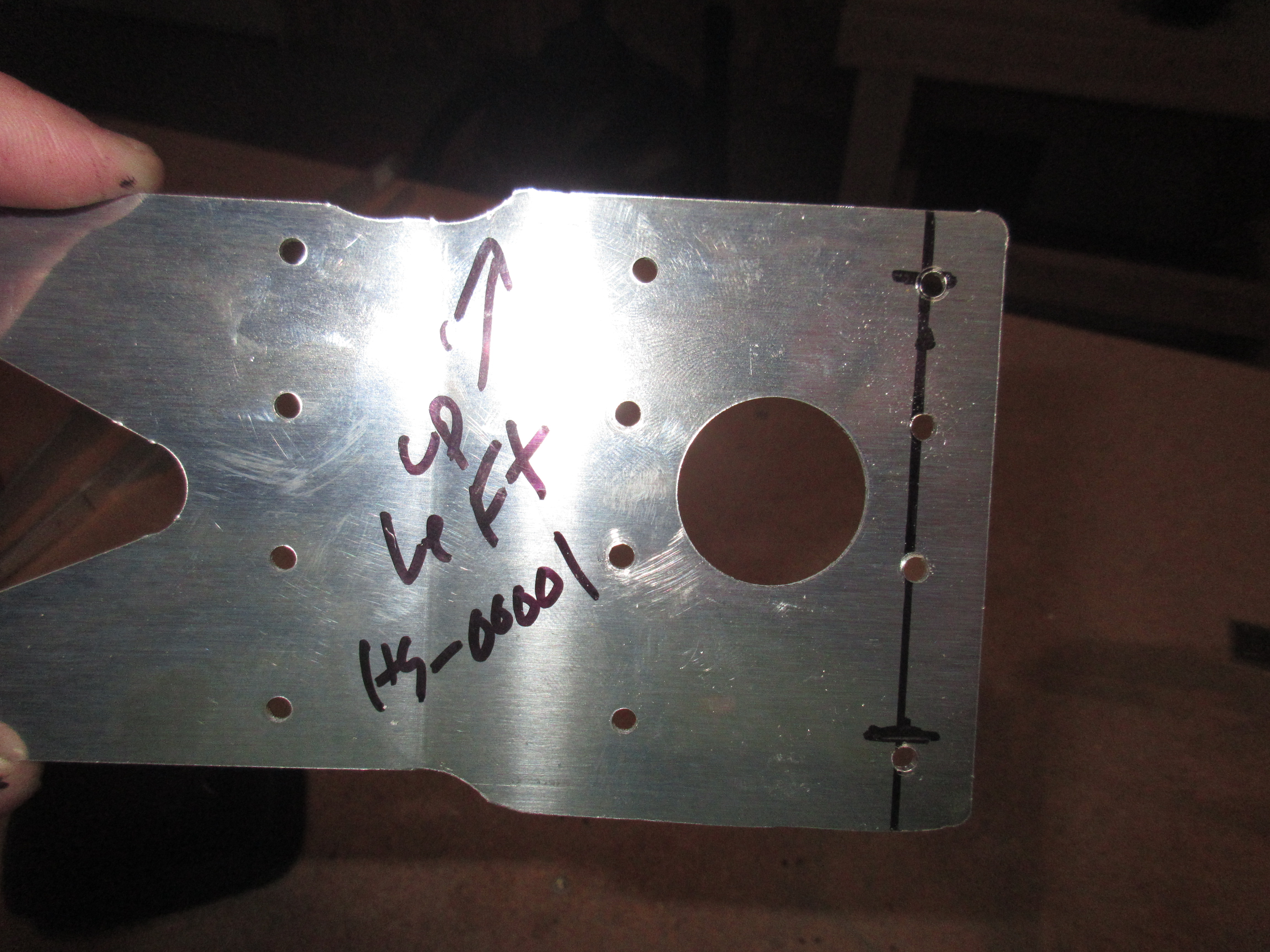
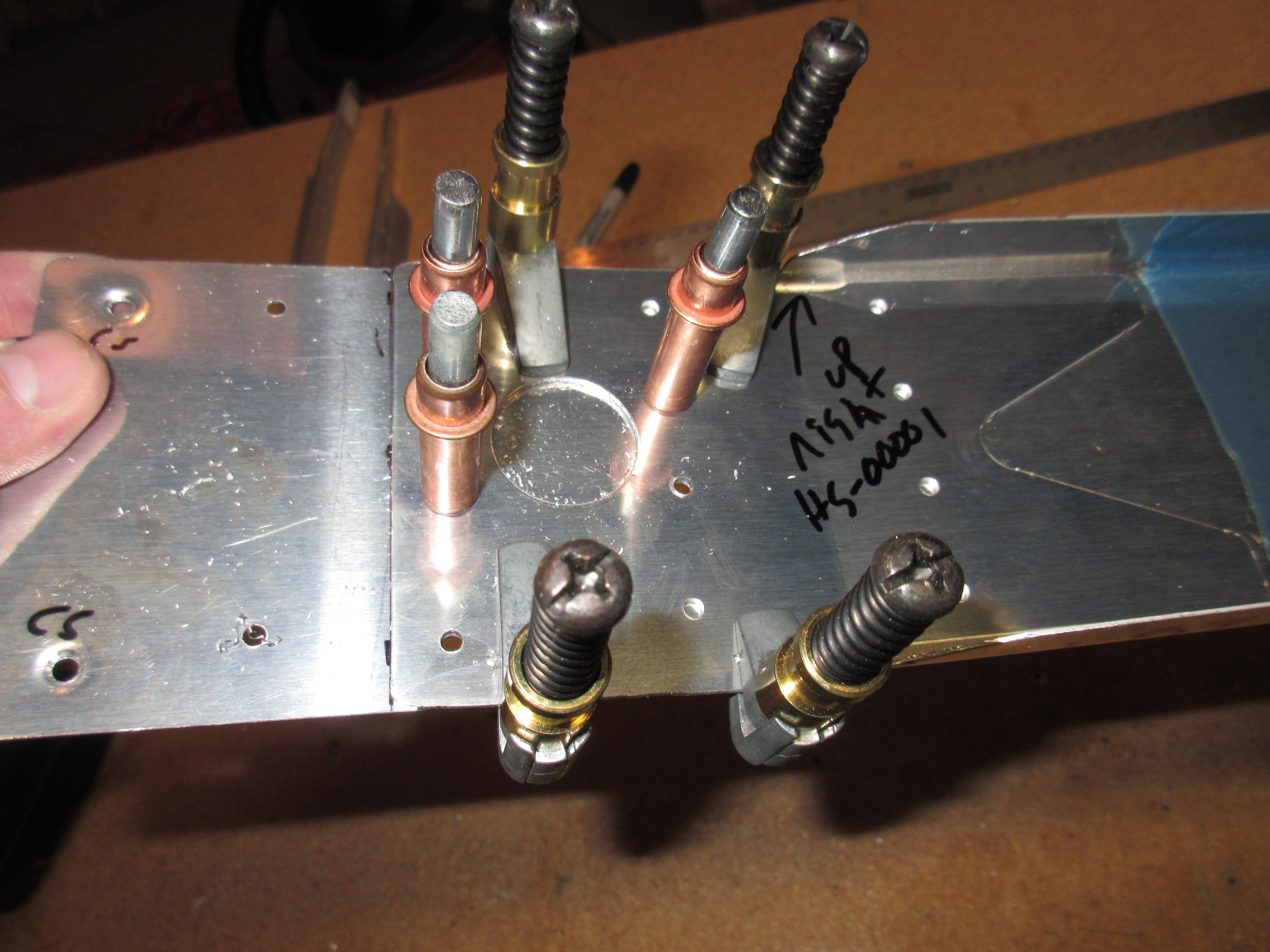
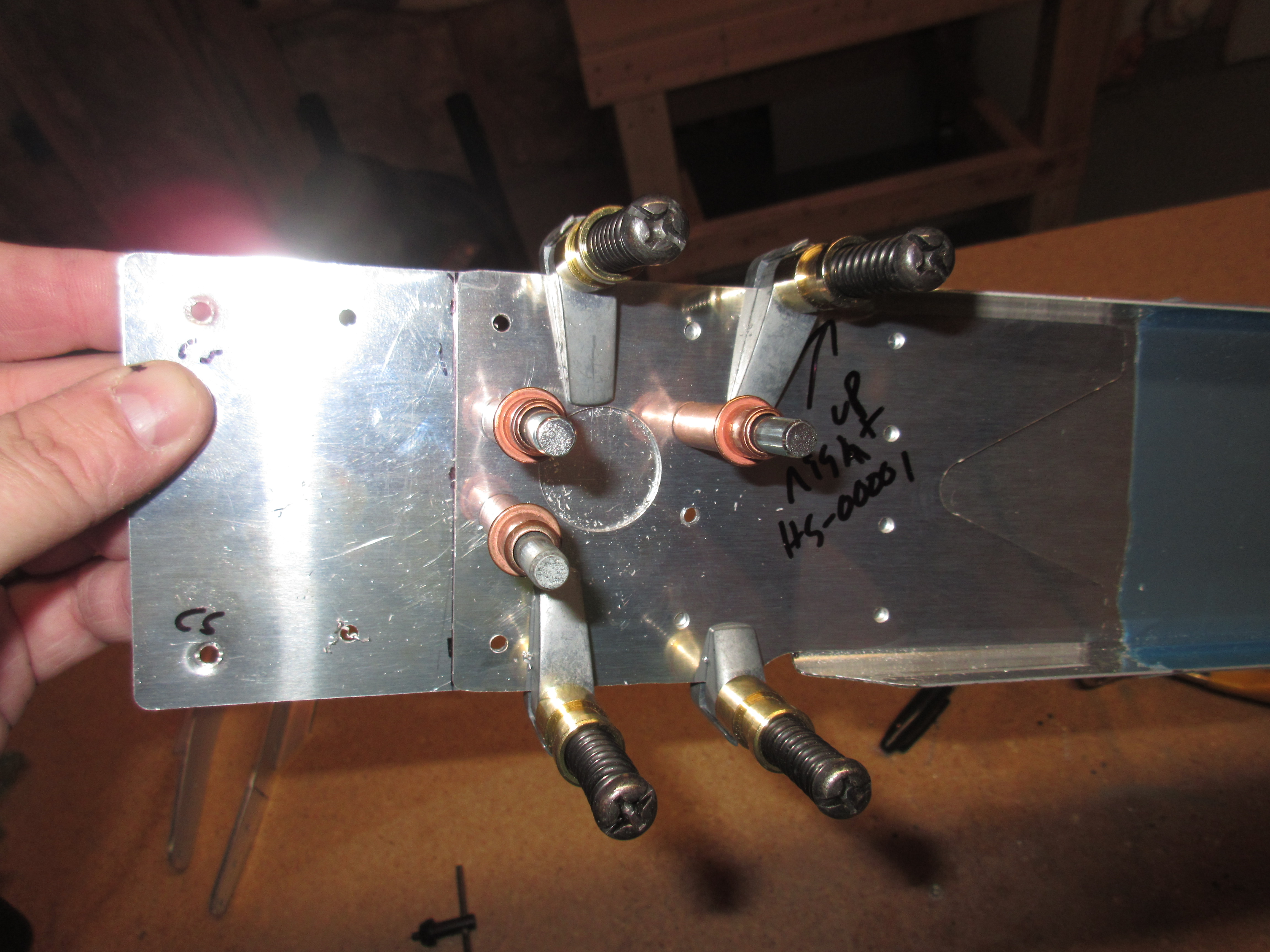
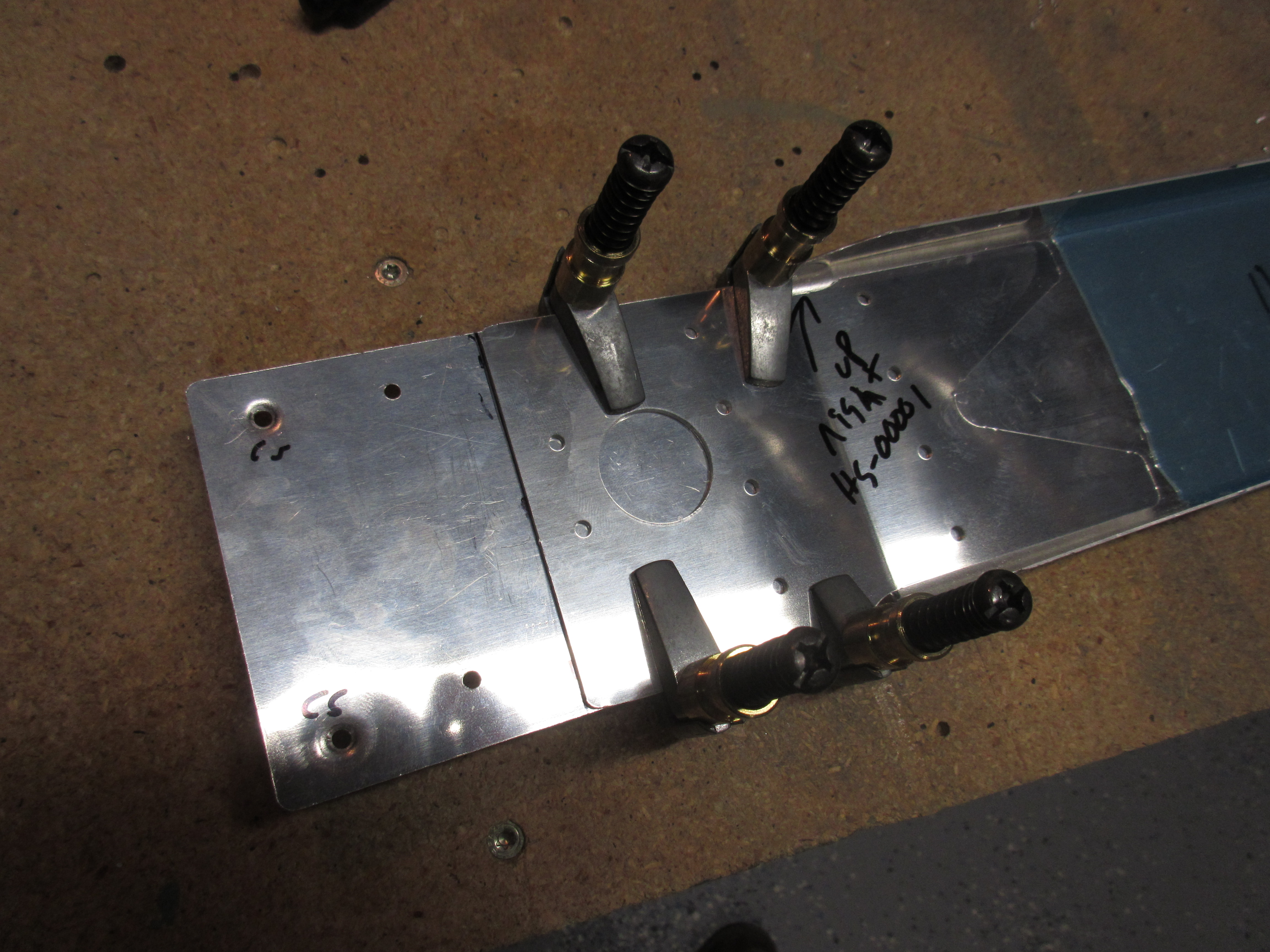
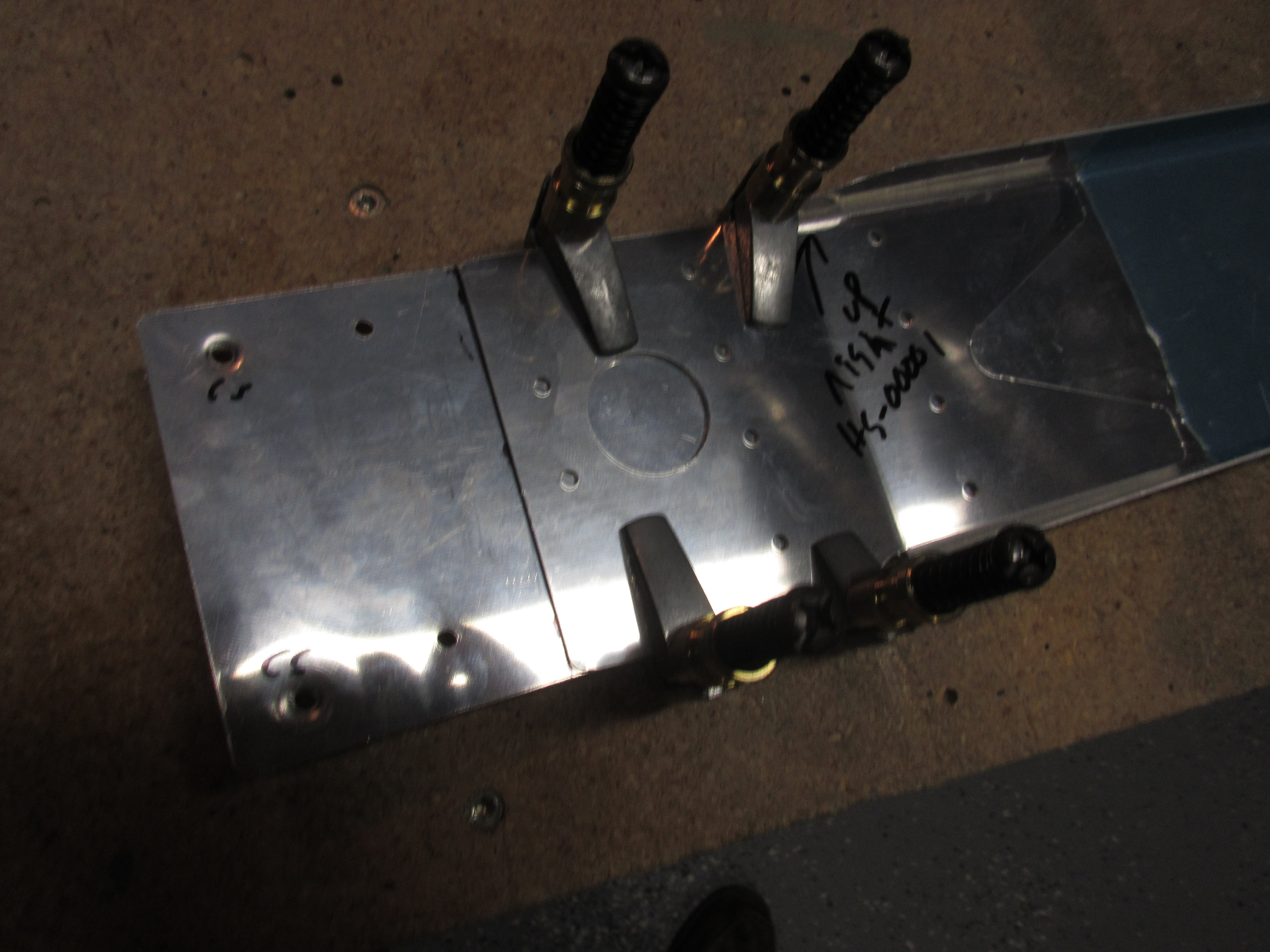
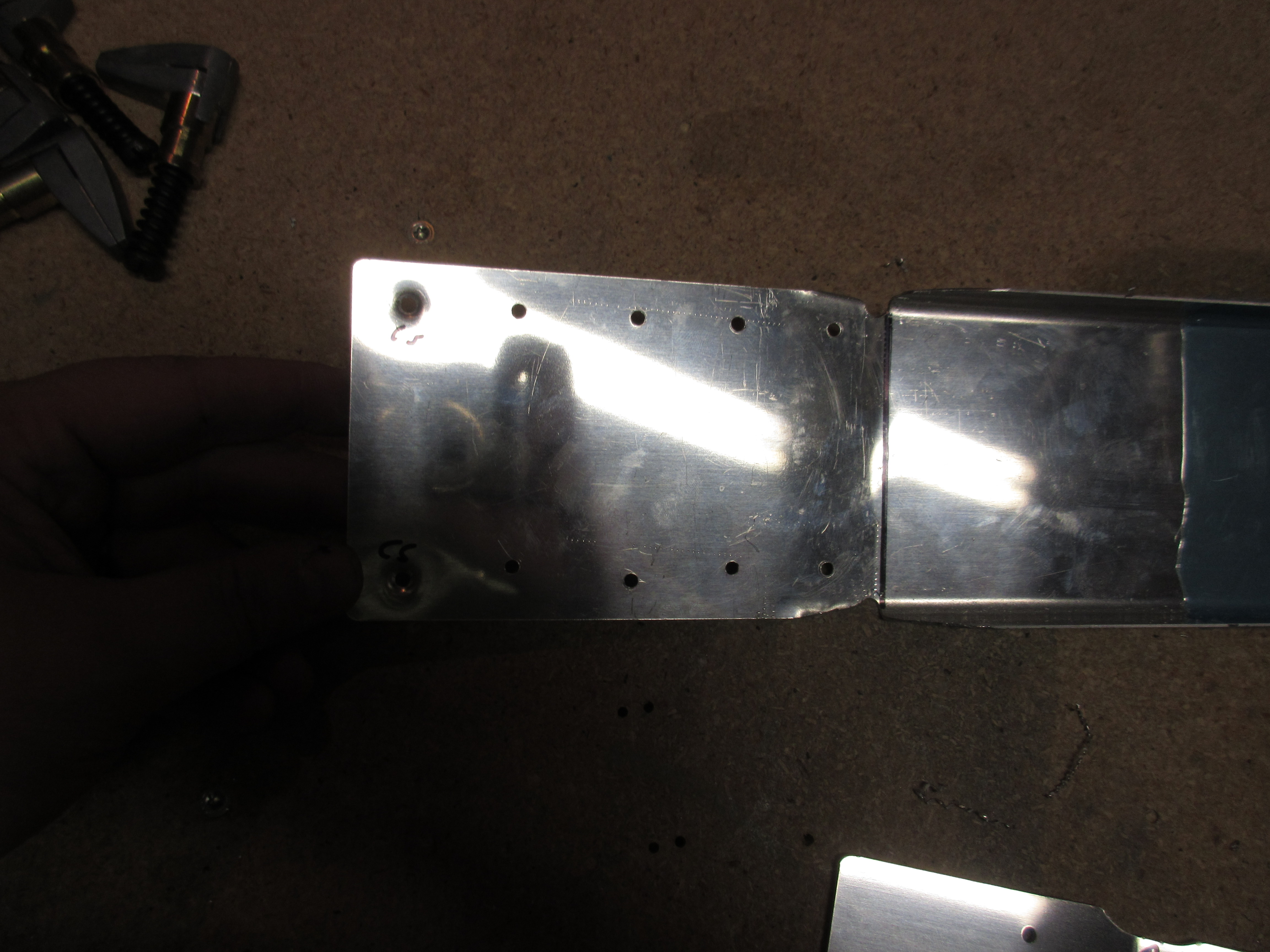
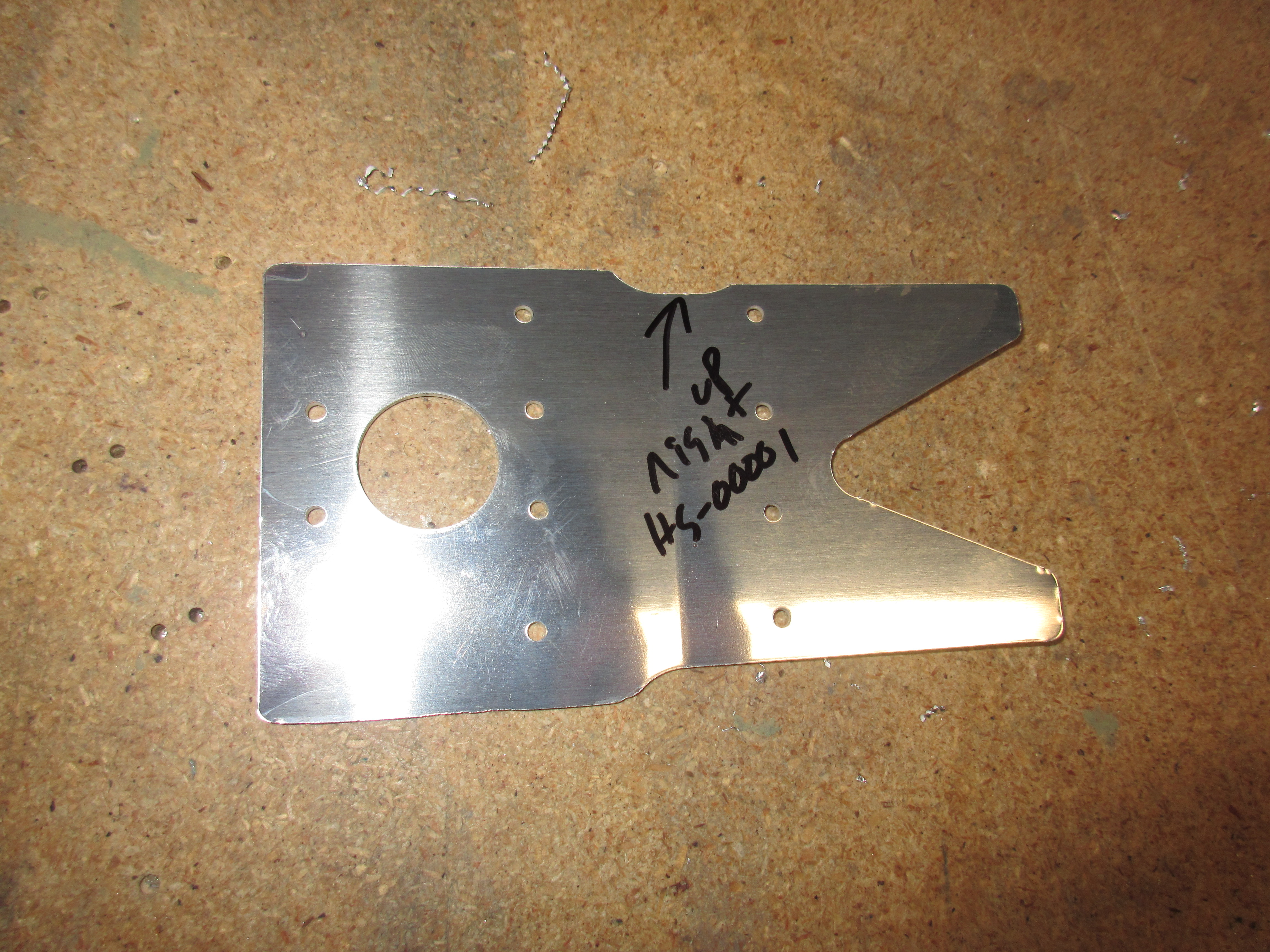
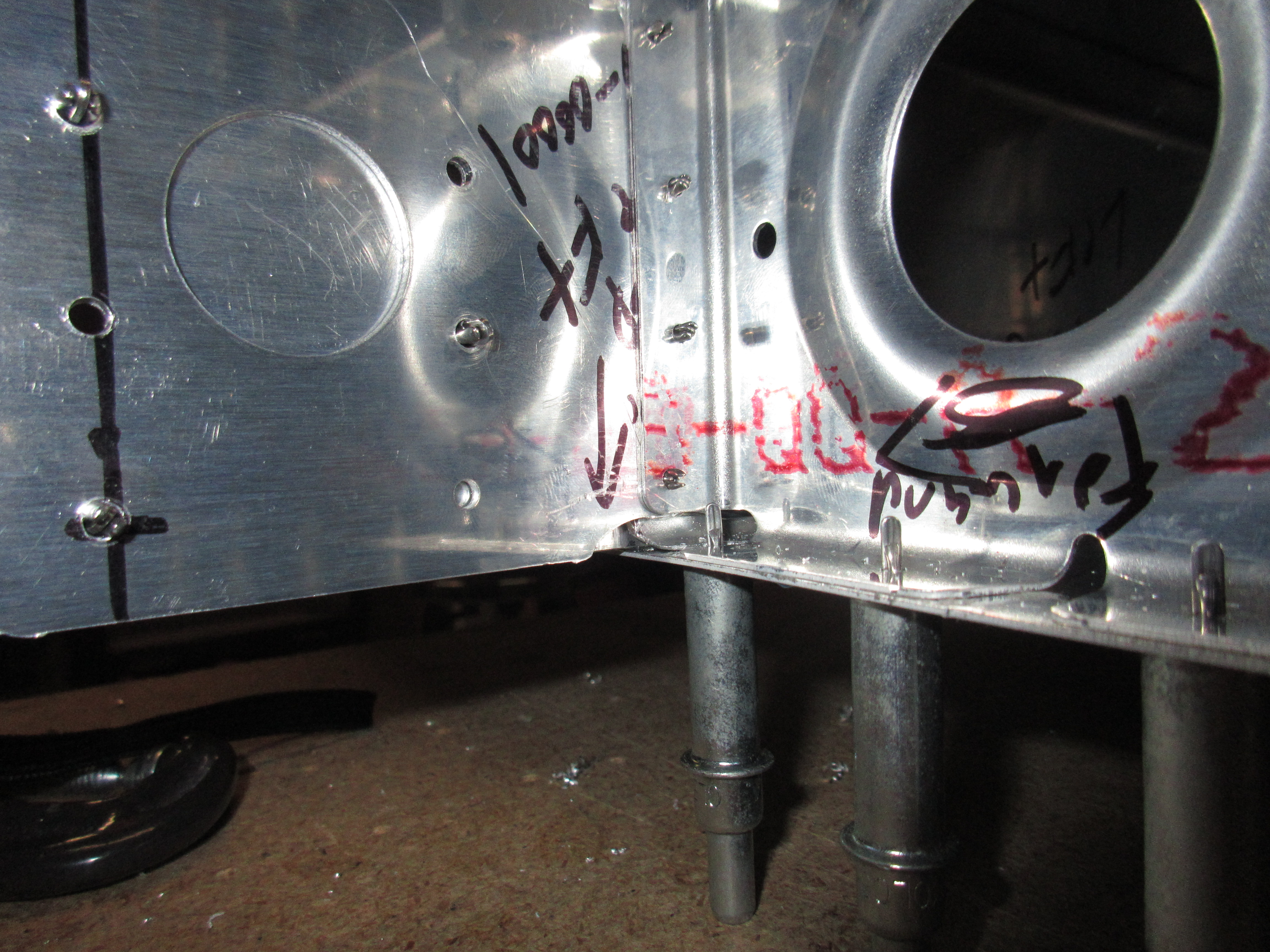
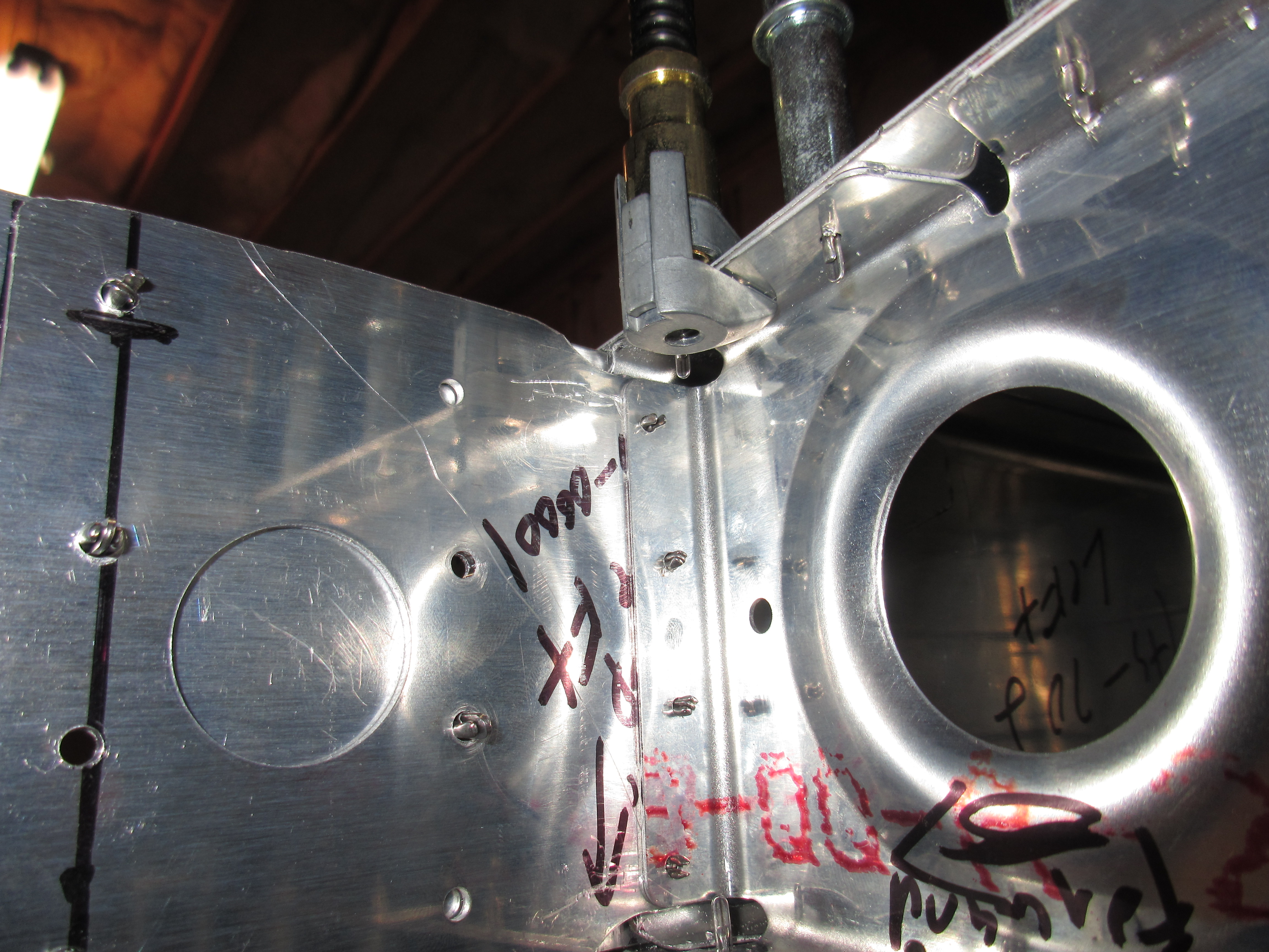
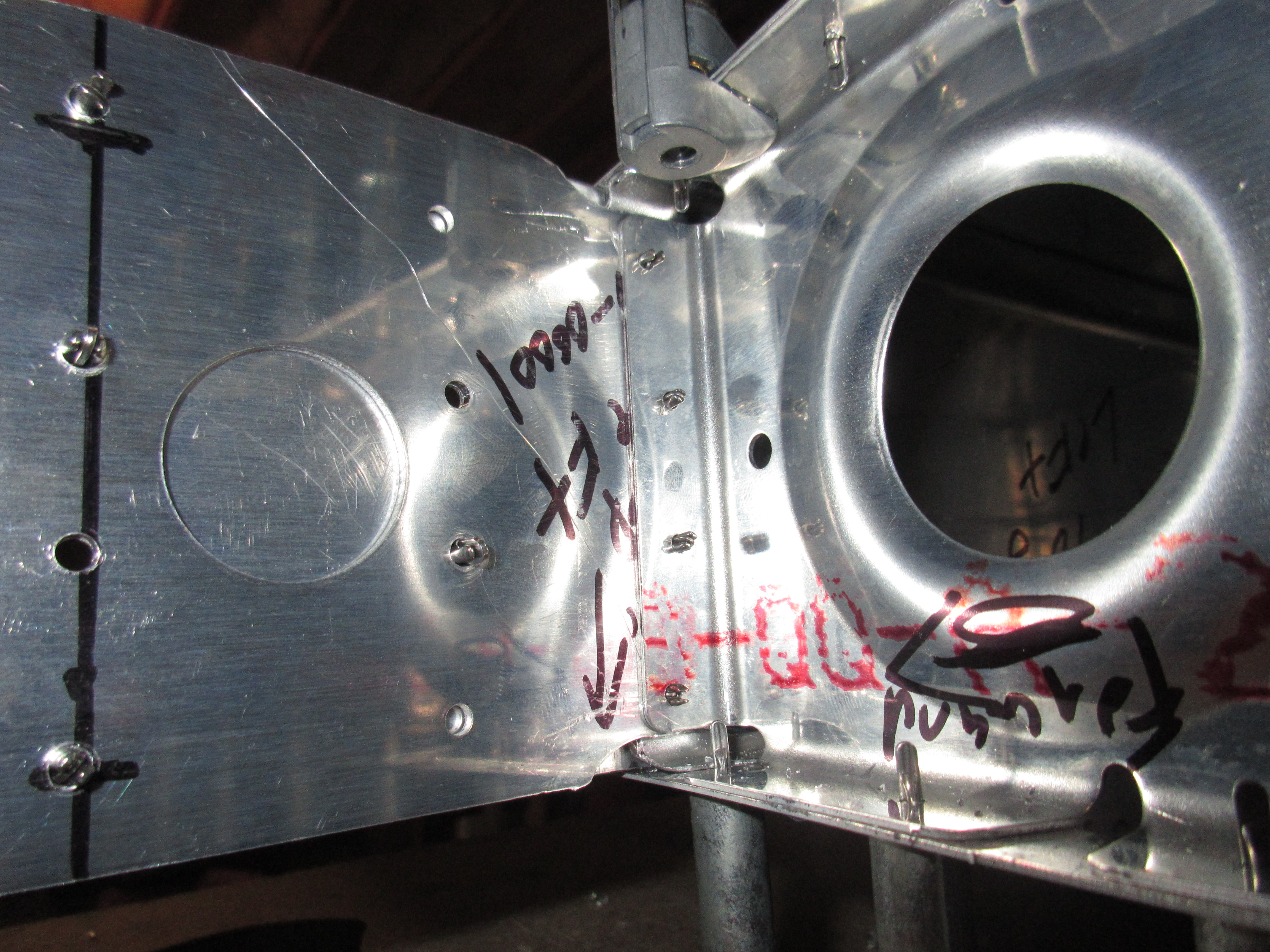
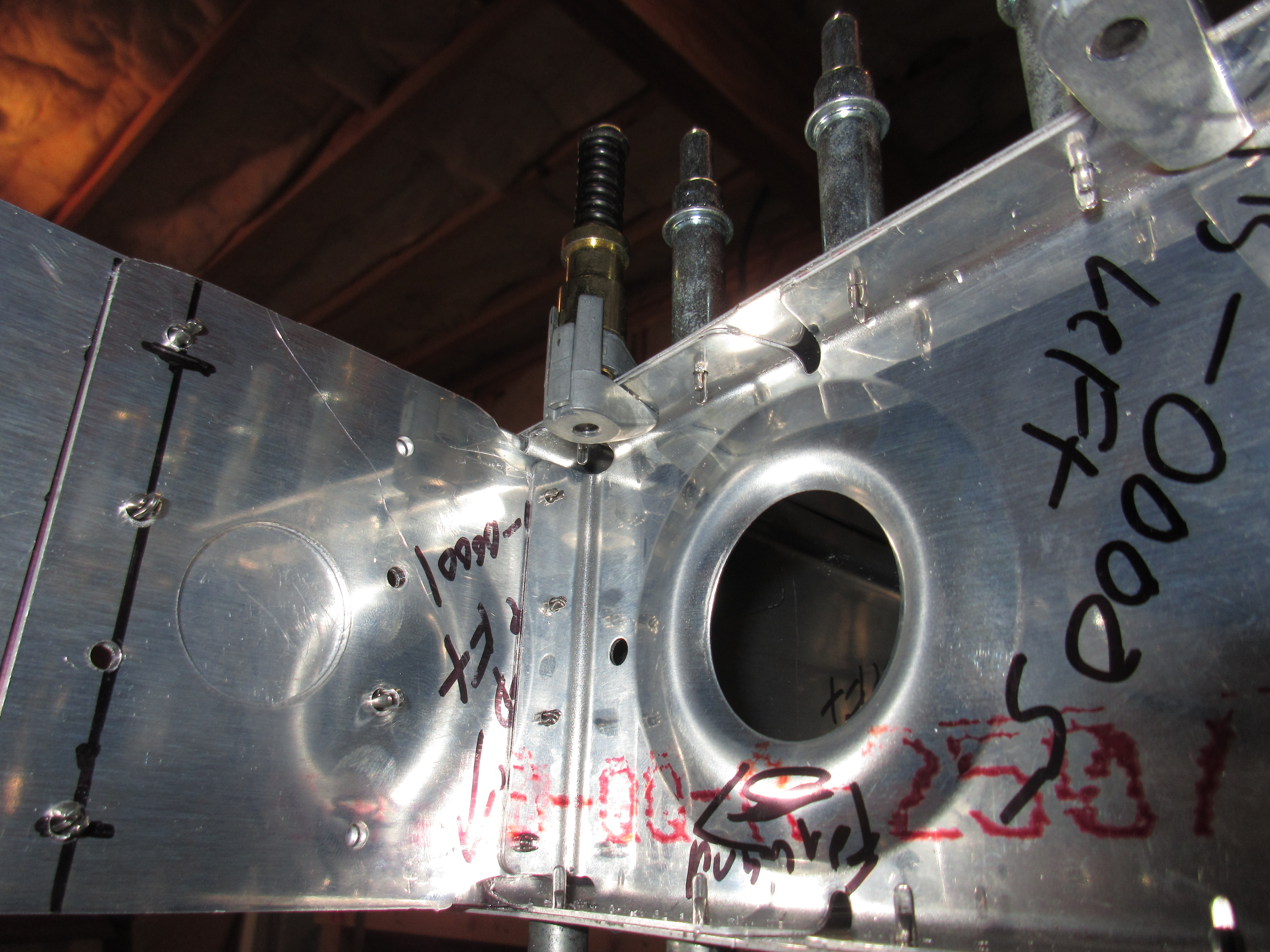
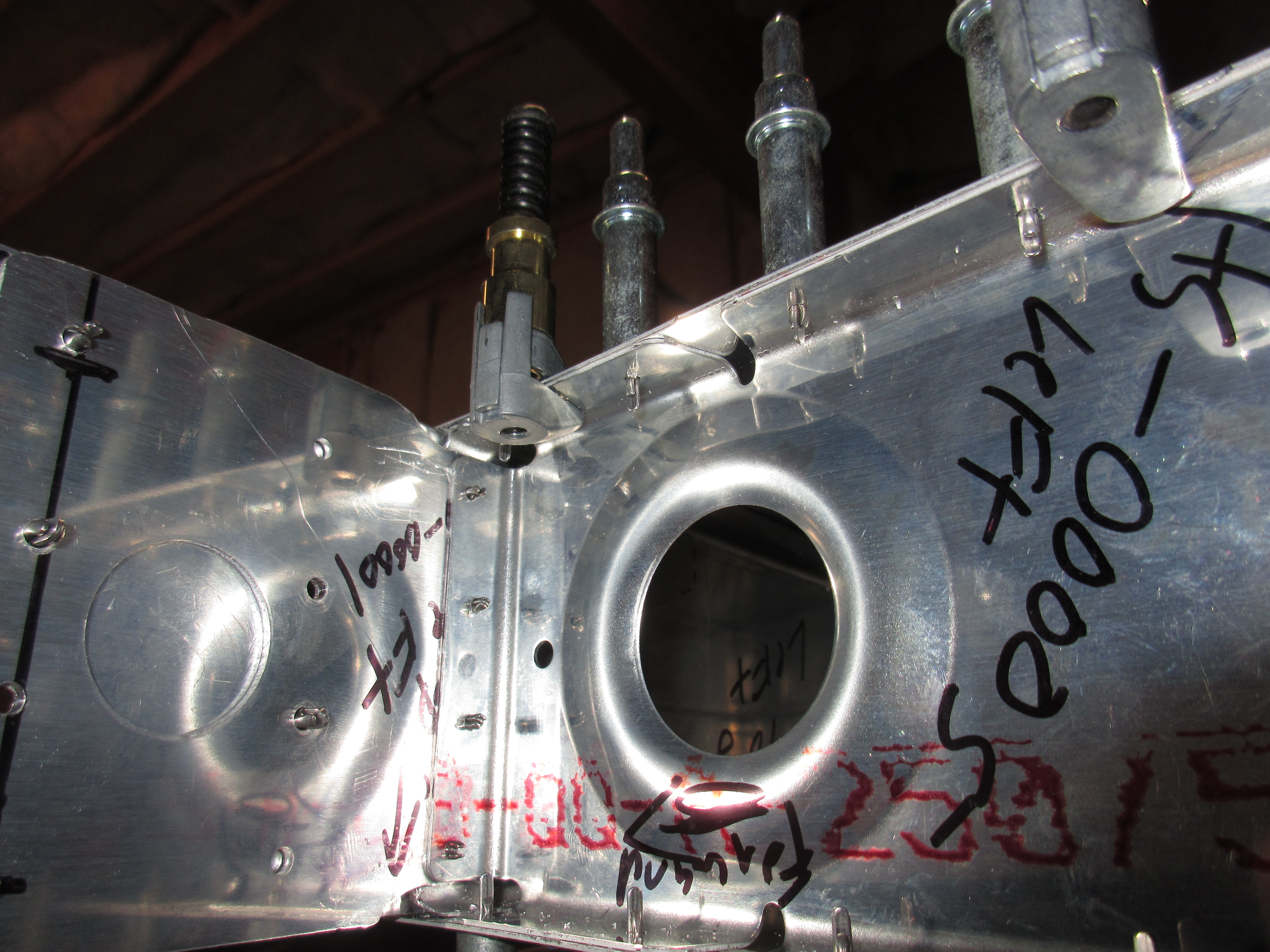
I am still a bit confused as to how the HS-00001 doublers go into place, but I will read the SB some more and try cleco’ing everything together and lining them up before final prep and assembly. I left a note in my plans to come back to this.

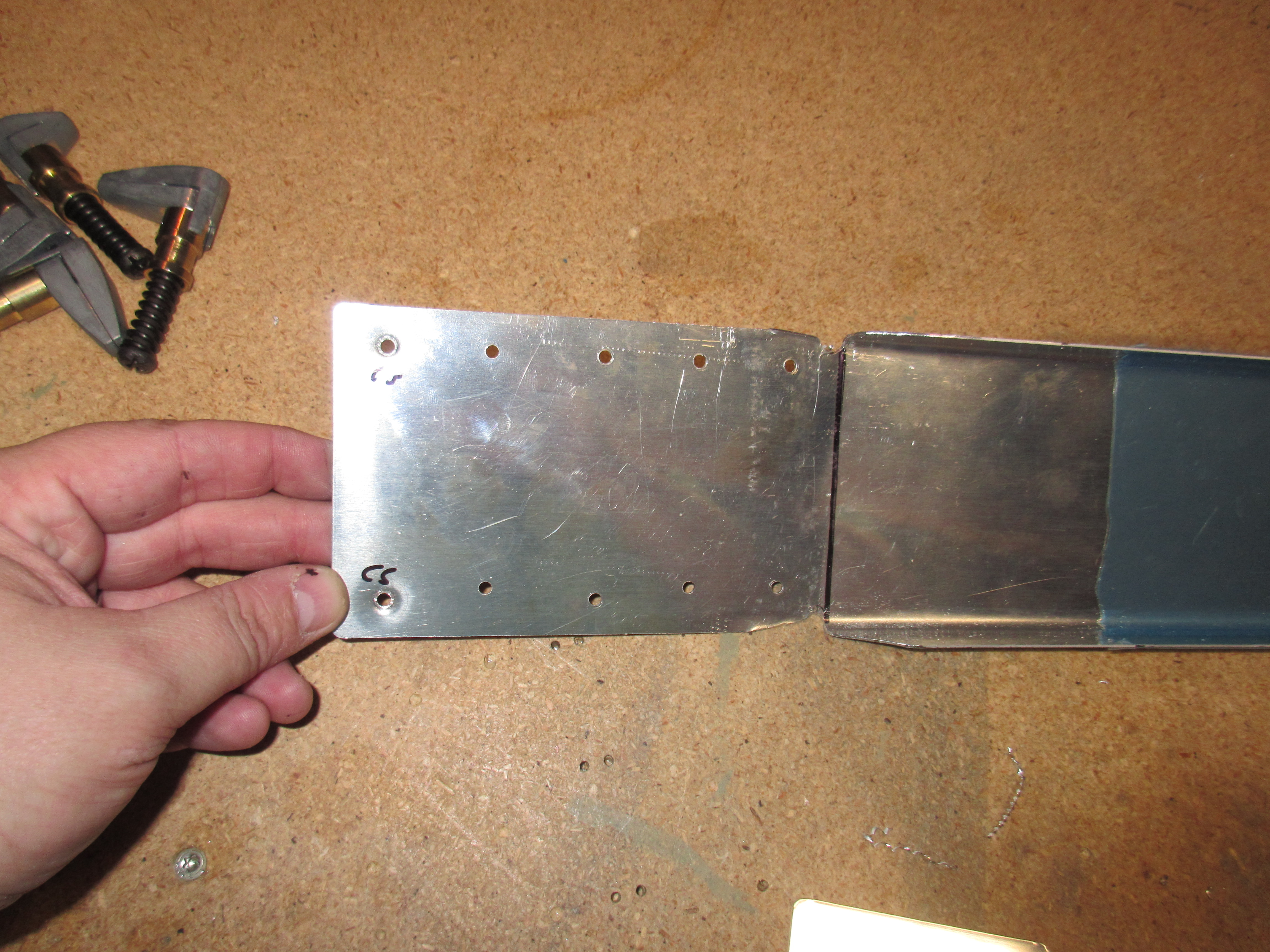
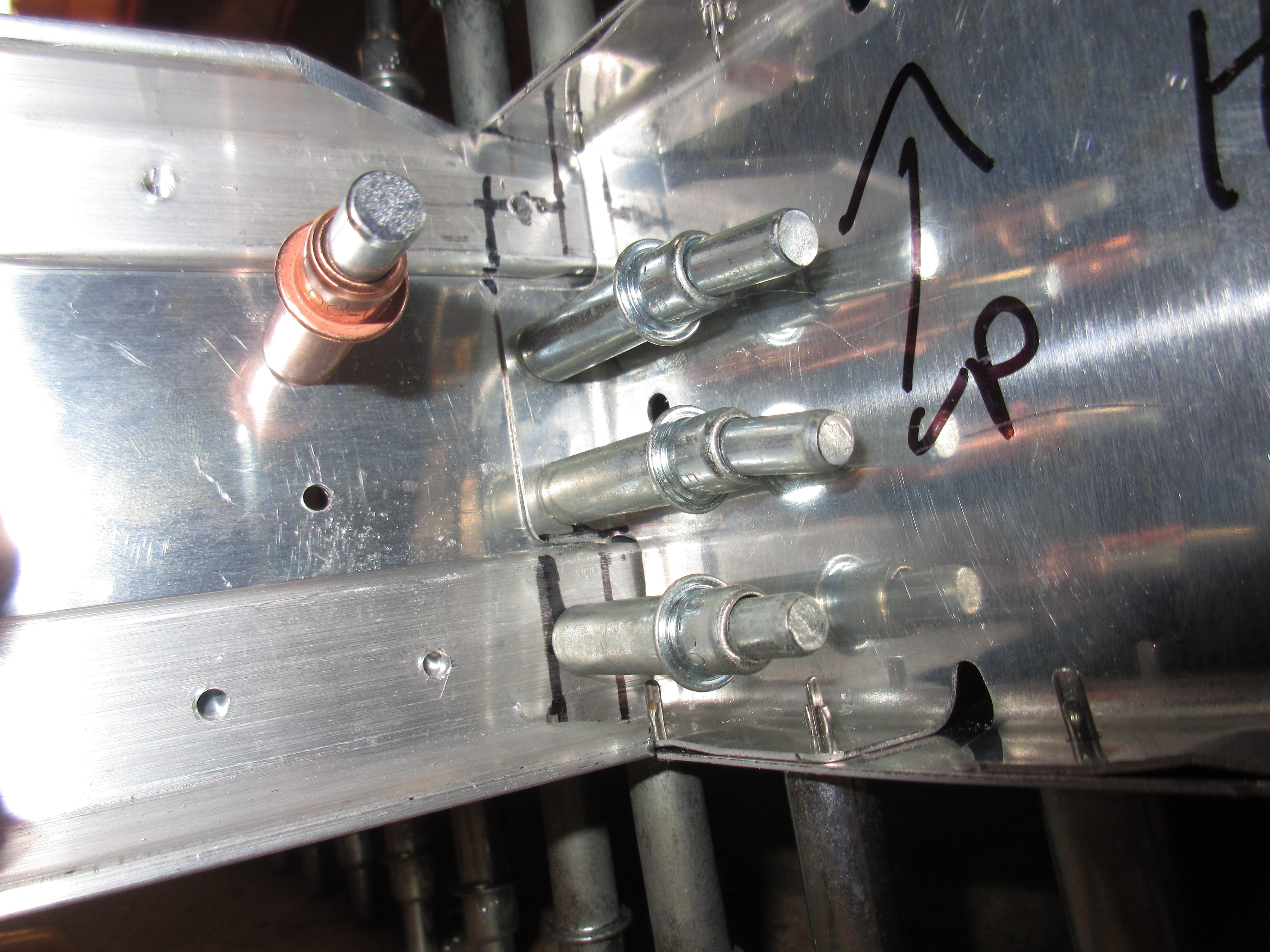
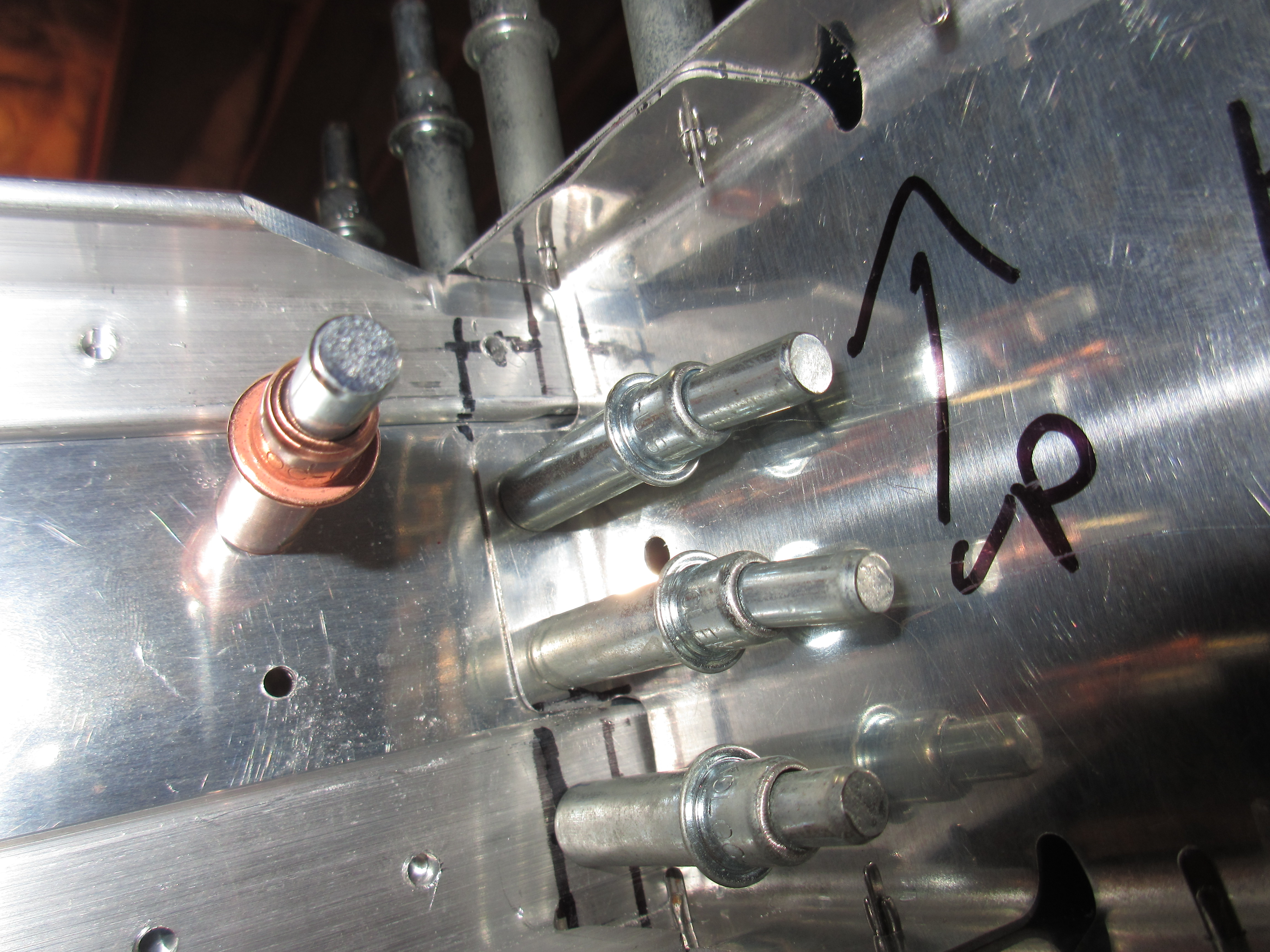
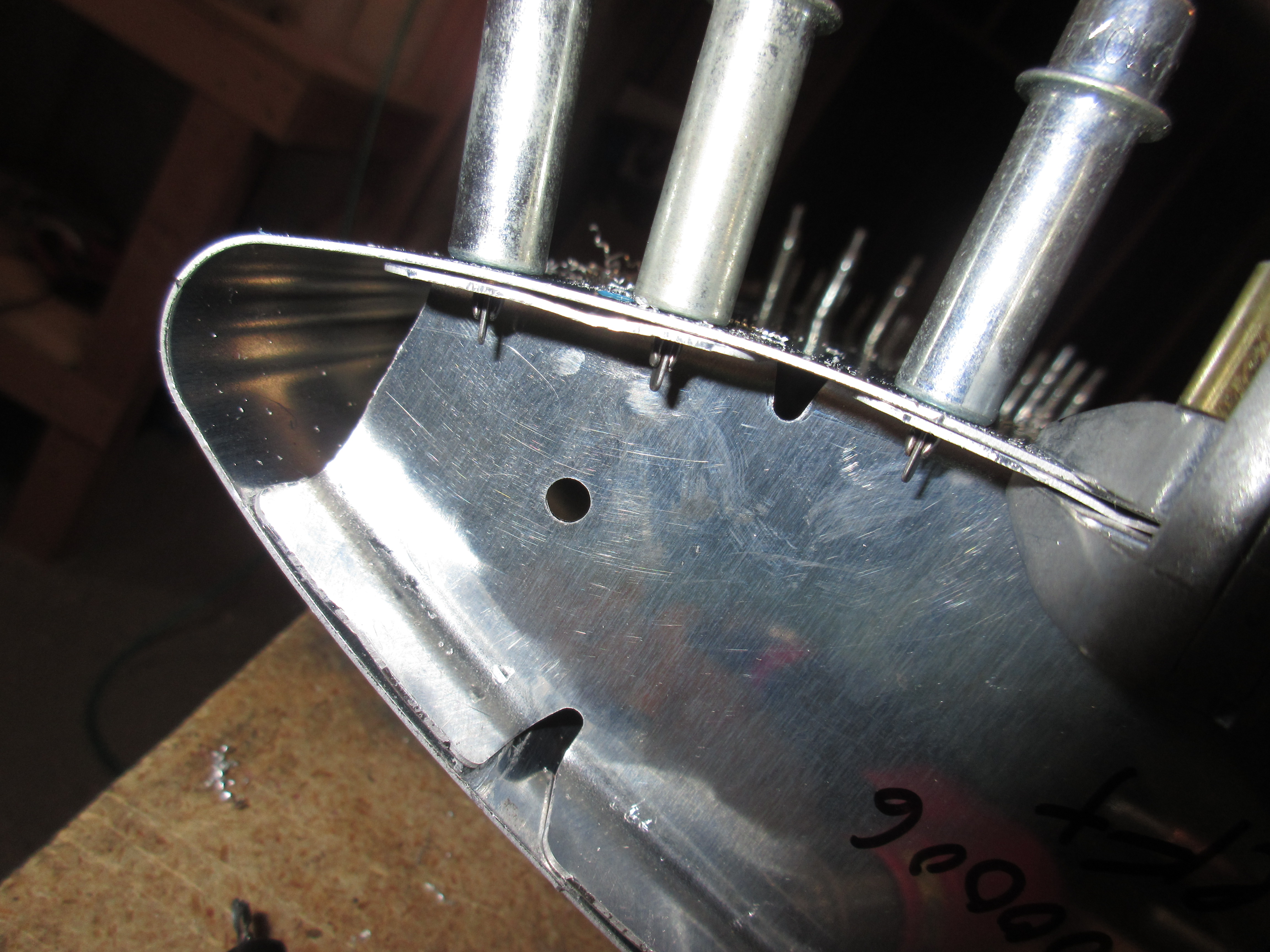
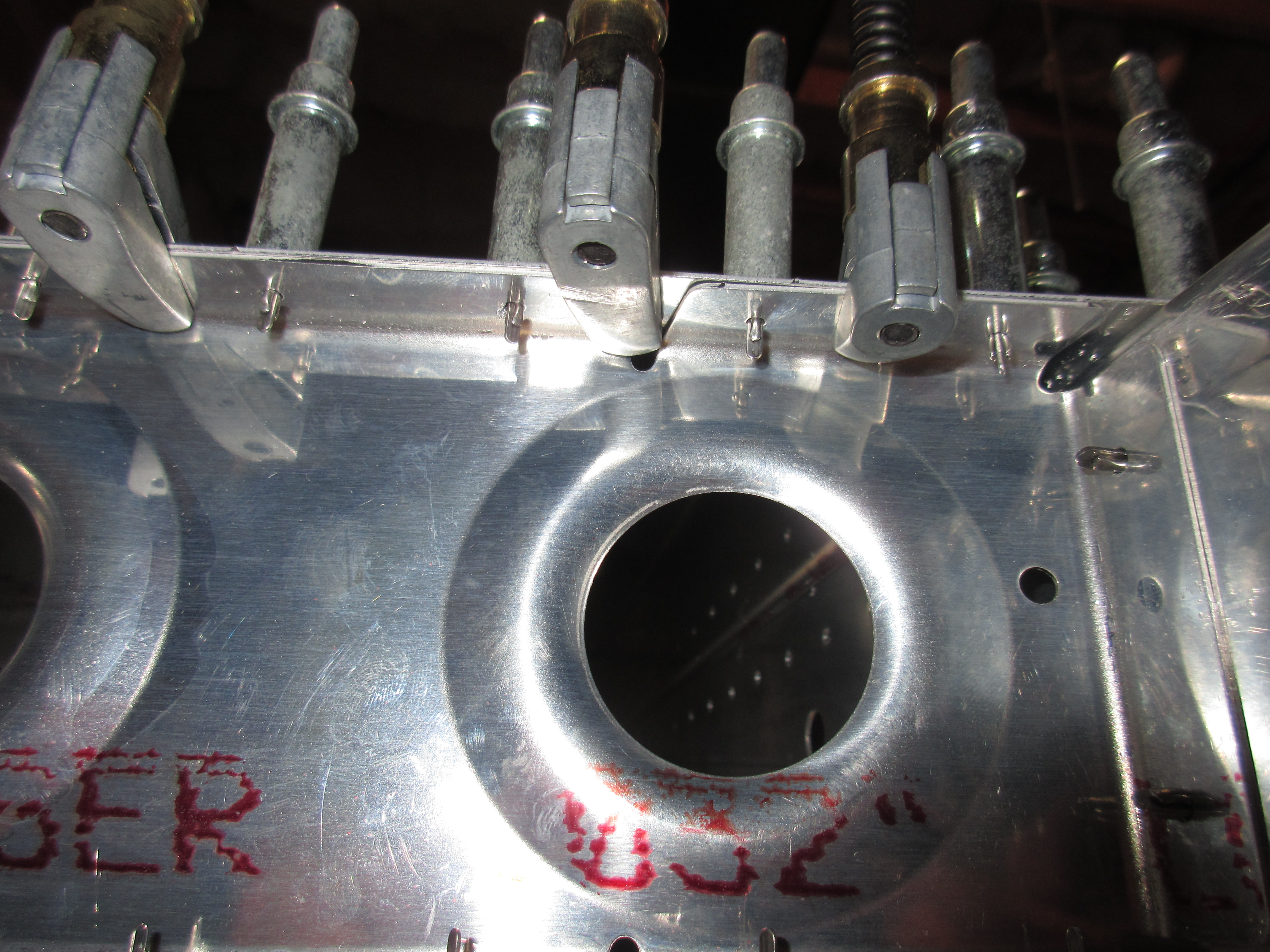
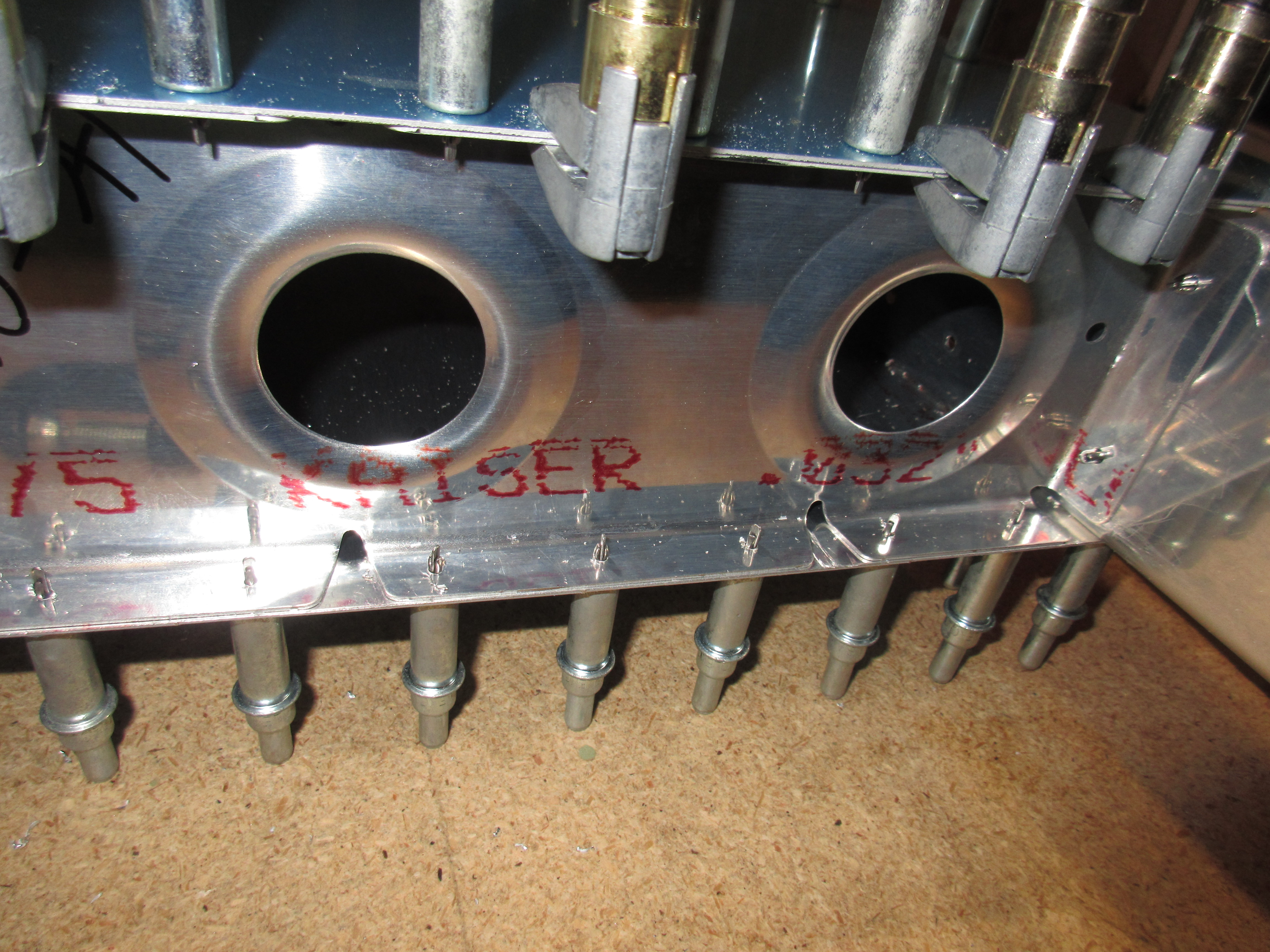
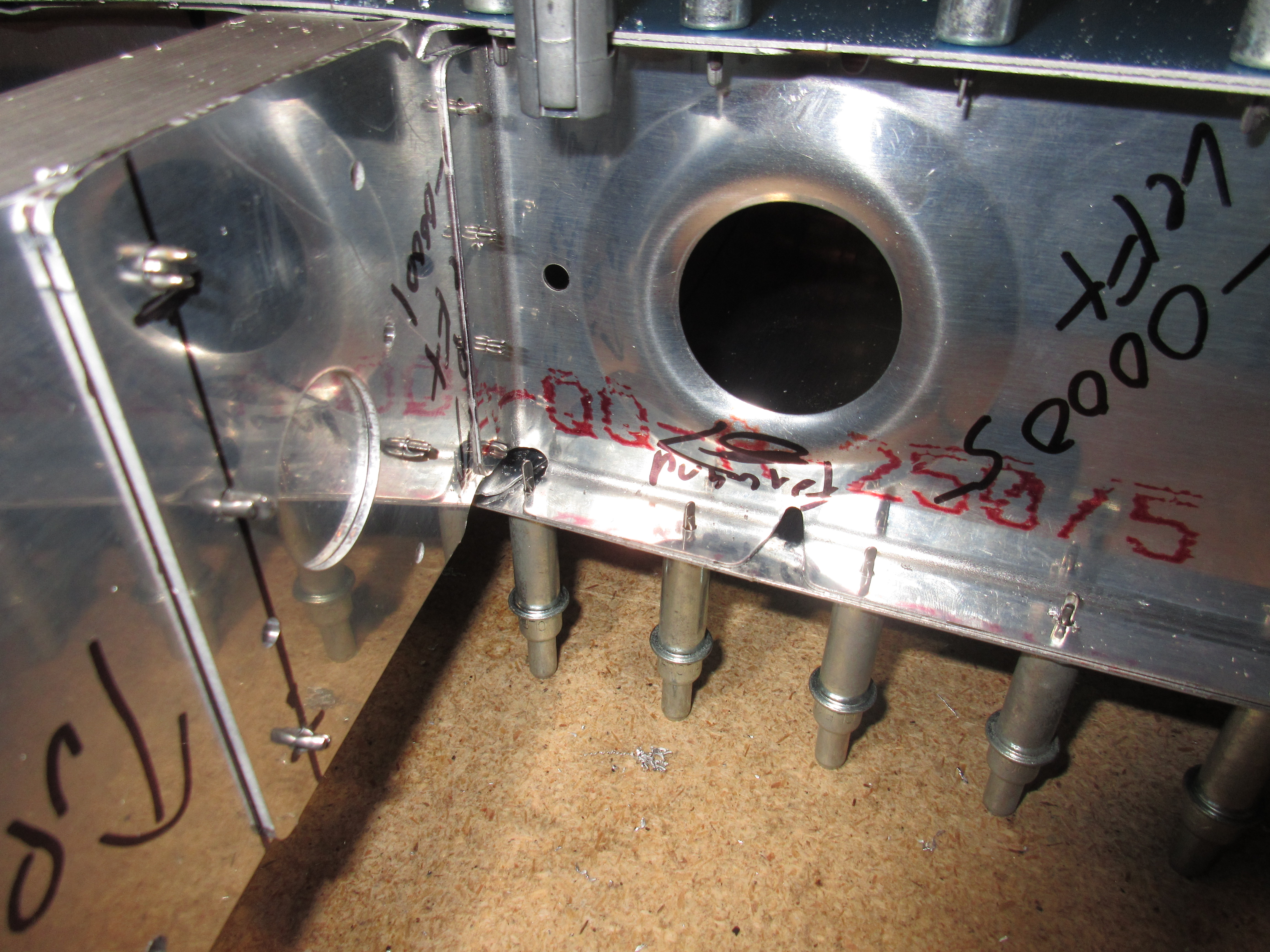
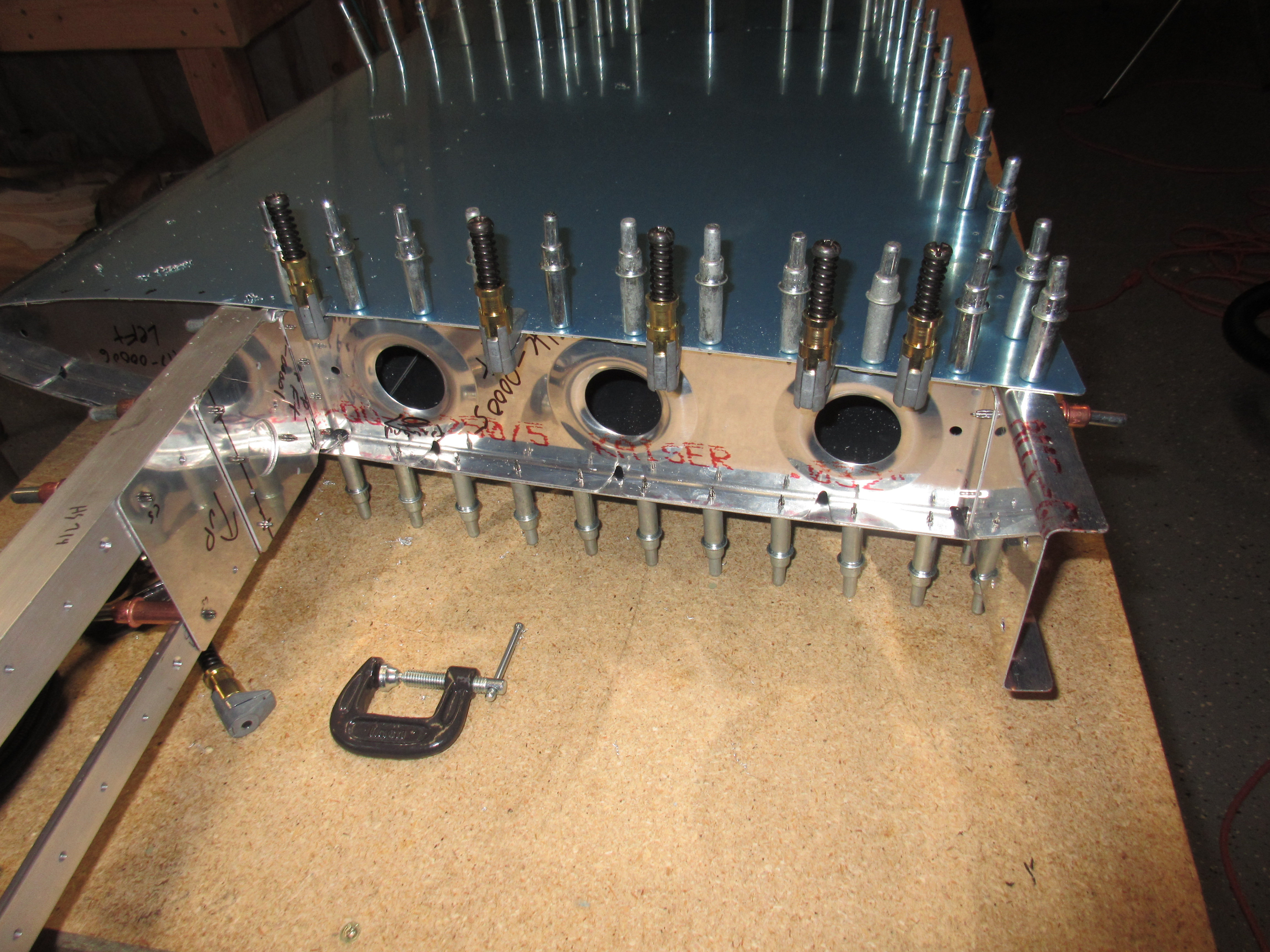
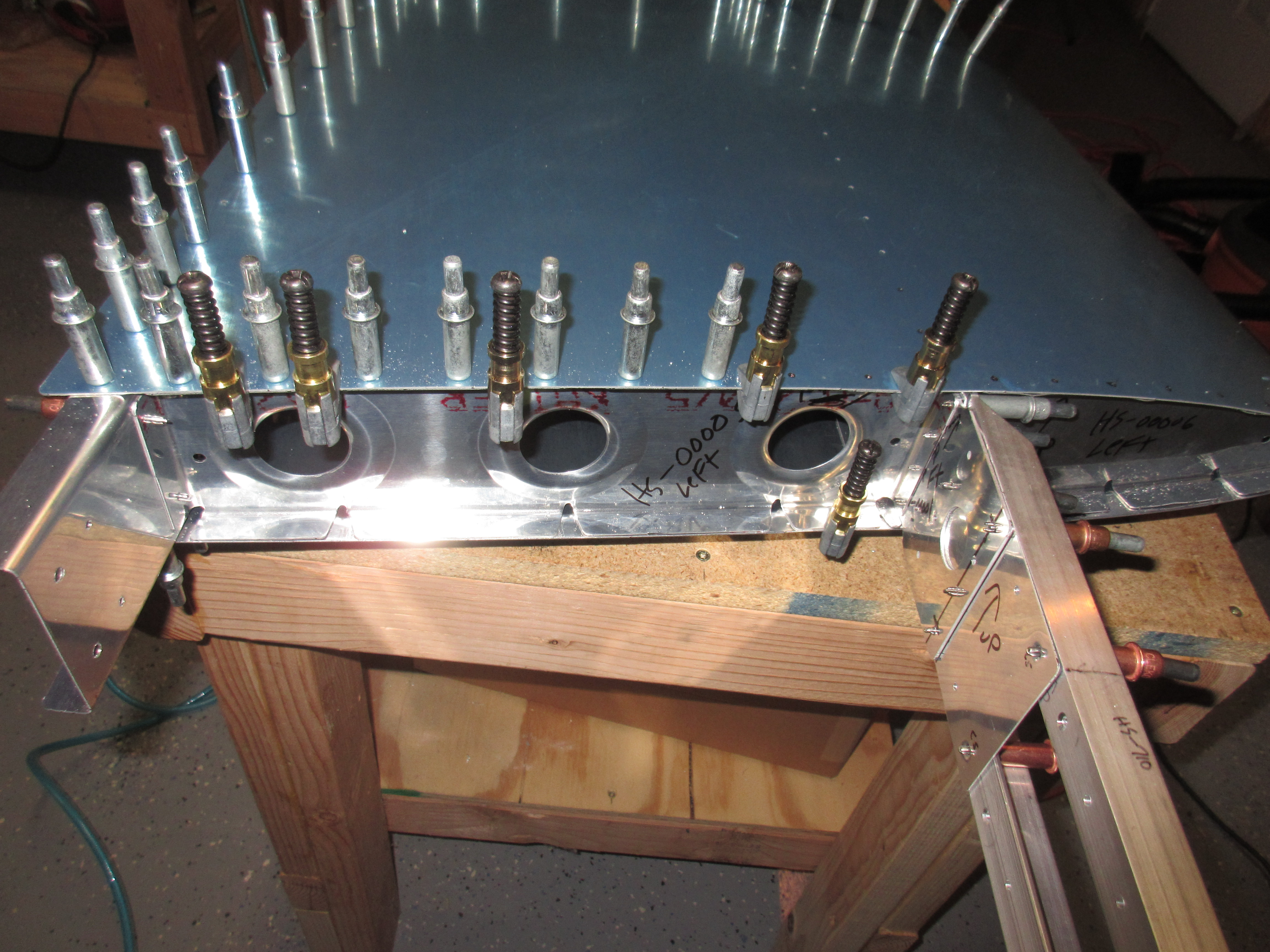
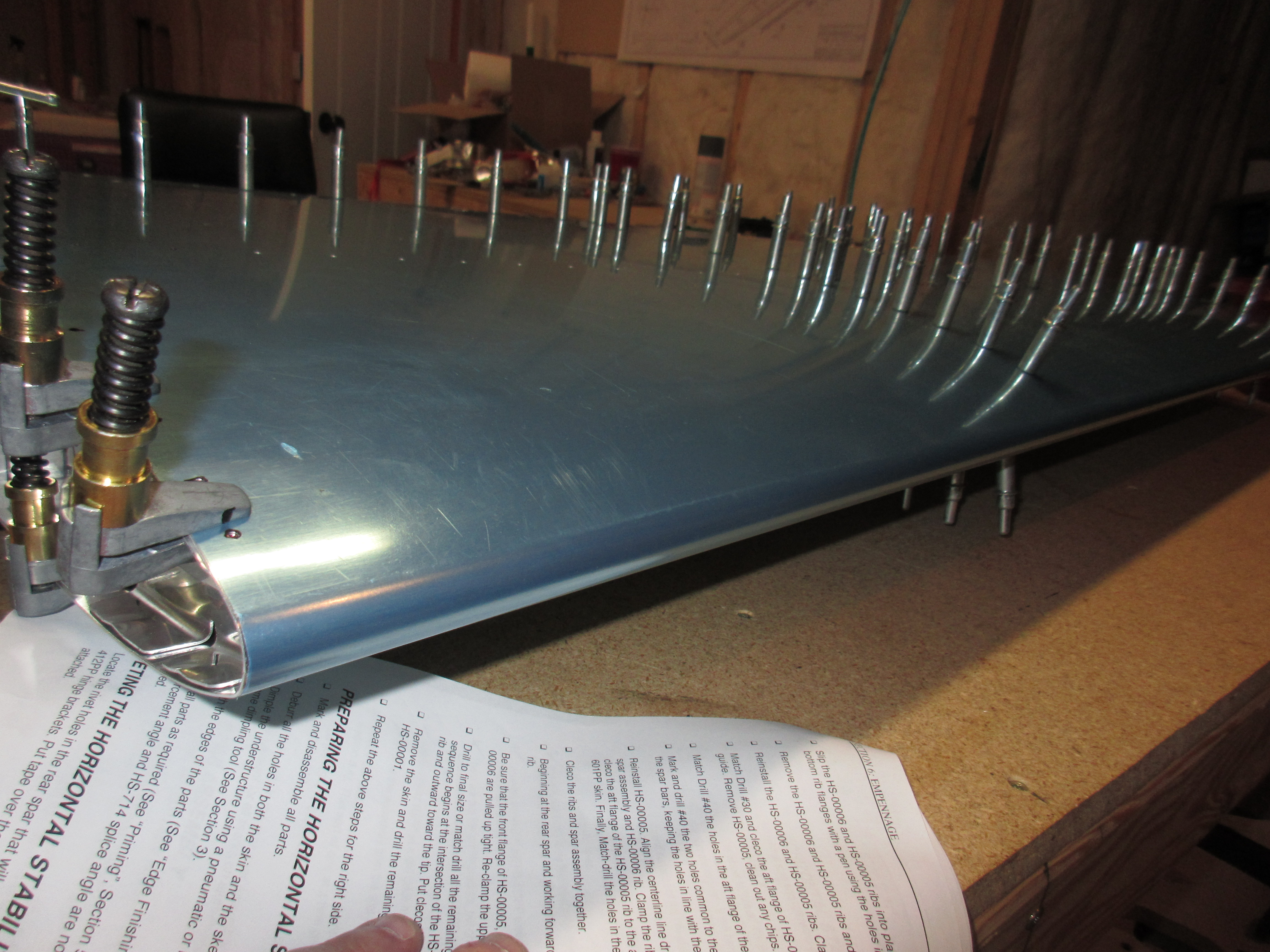
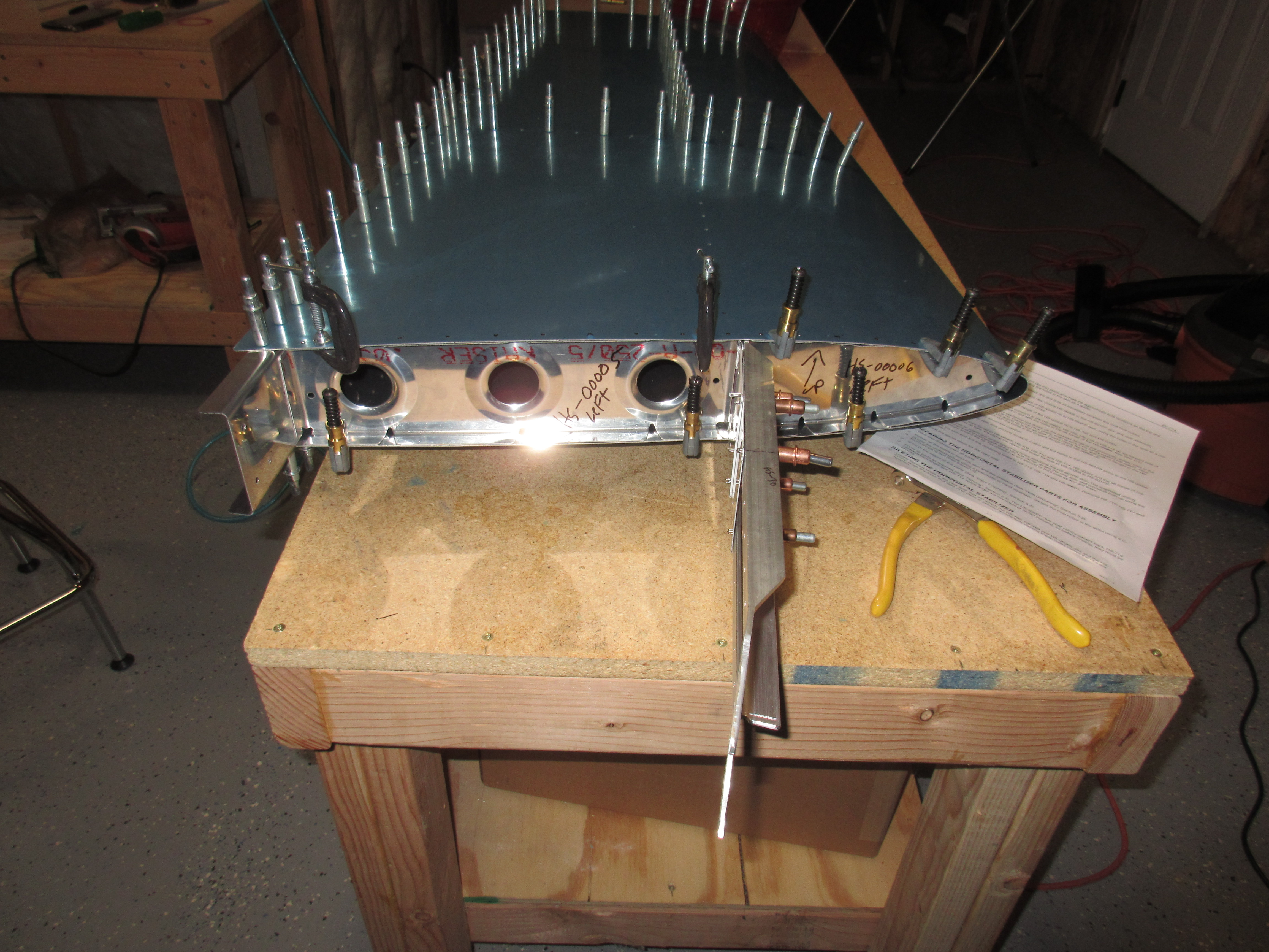
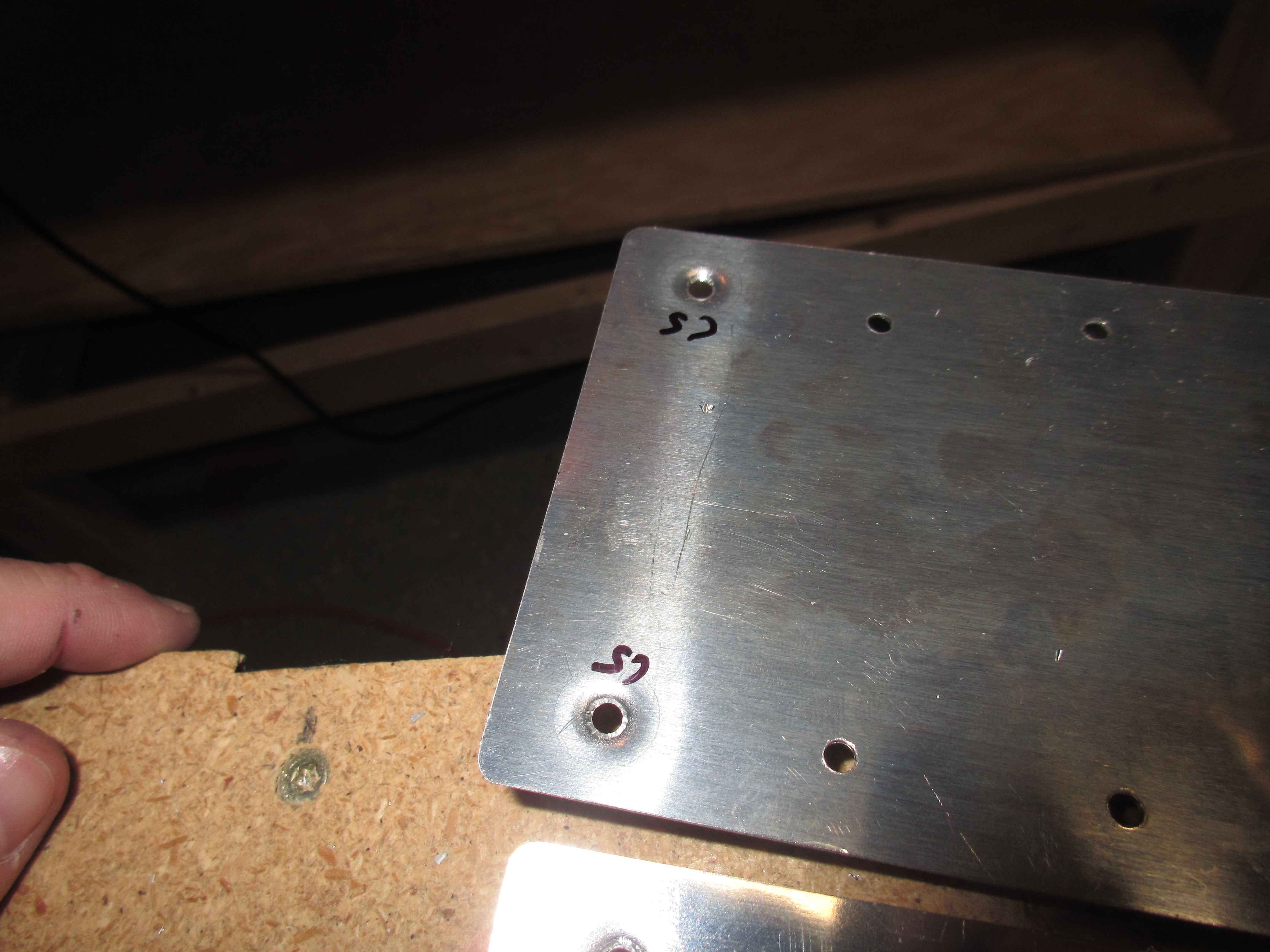
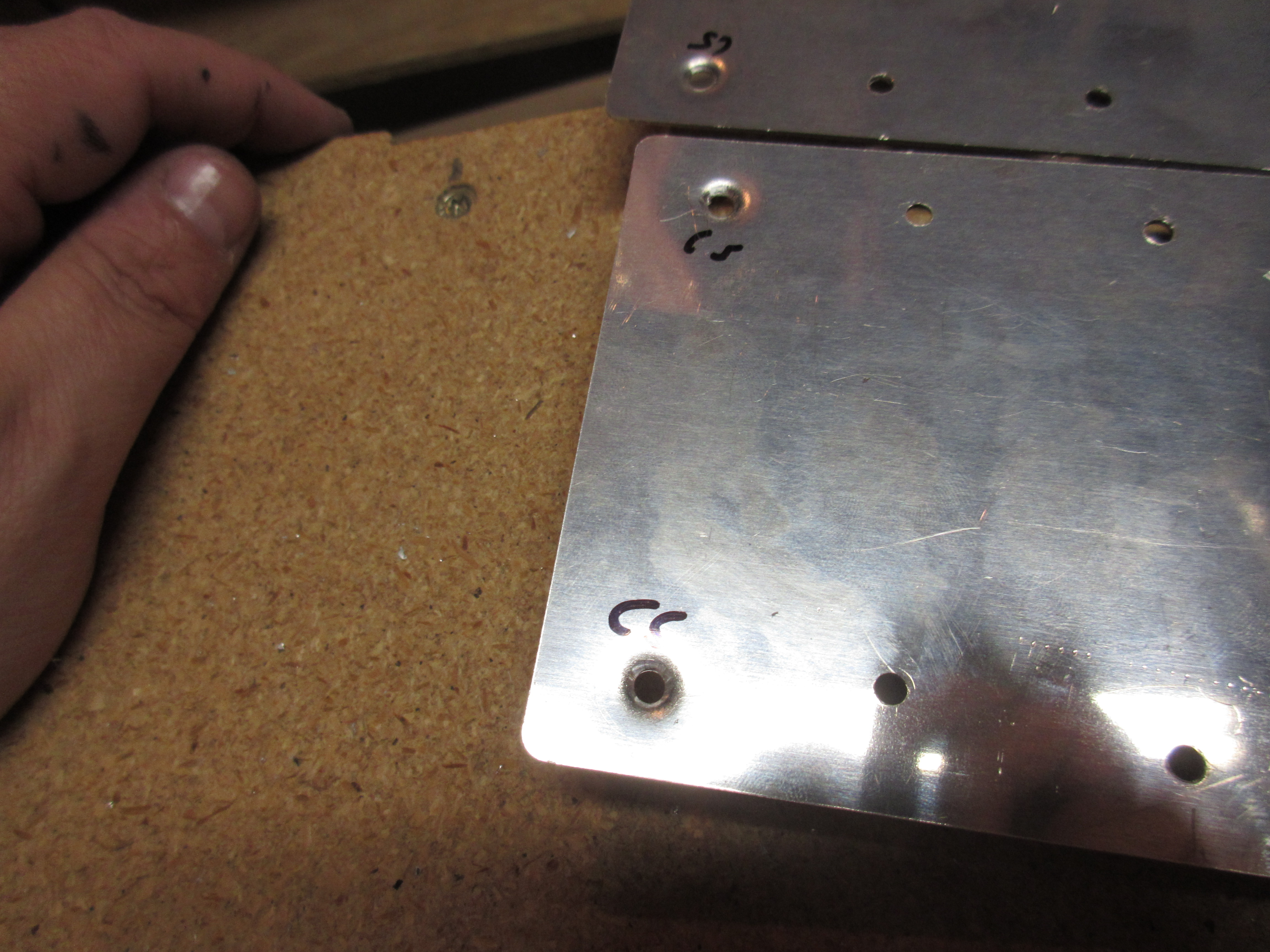
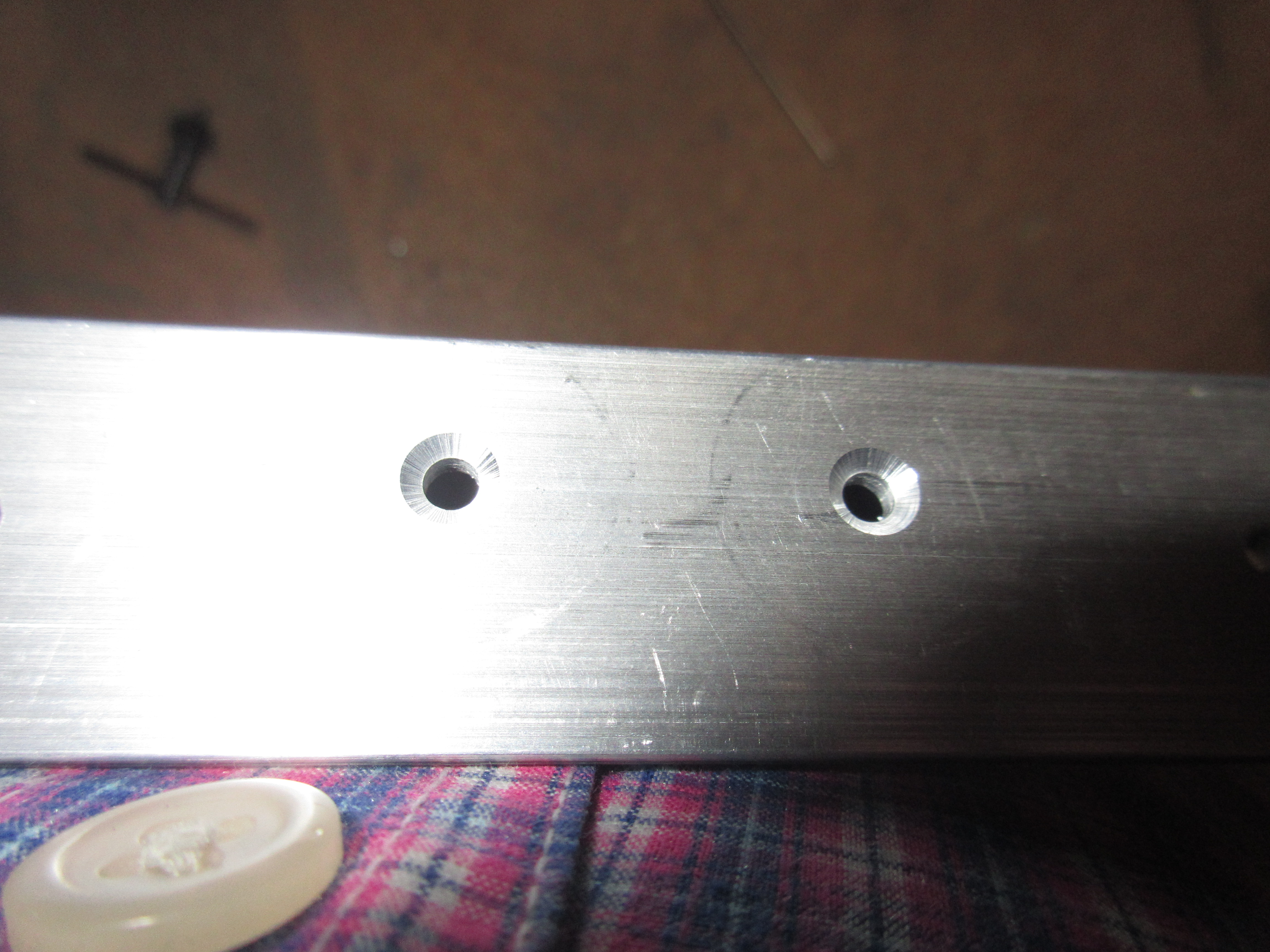
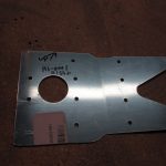
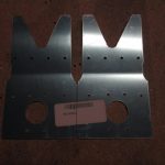
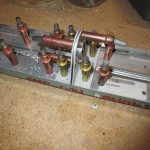
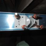
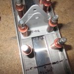
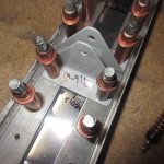
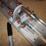
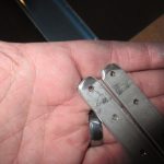
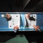
Then I moved on to the last step and that was to countersink the holes needed on the front spar HS-702, HS-710 and HS-714. The plans state that the inner 4 holes must be countersunk from with the flush head facing aft. So, I setup my countersink cage using some scrap and a AN4264-4 rivet to get it at the perfect depth. Then I drilled the 2 center holes on each the HS-710 and HS-714 angle support bars. I used my DRDT-2 dimpler to dimple the light metal of the spar channel then test fit everything back together with clecos. They dimpled parts nestle together very nicely with no gaps. I was happy to close out the front spar assembly section with these results!

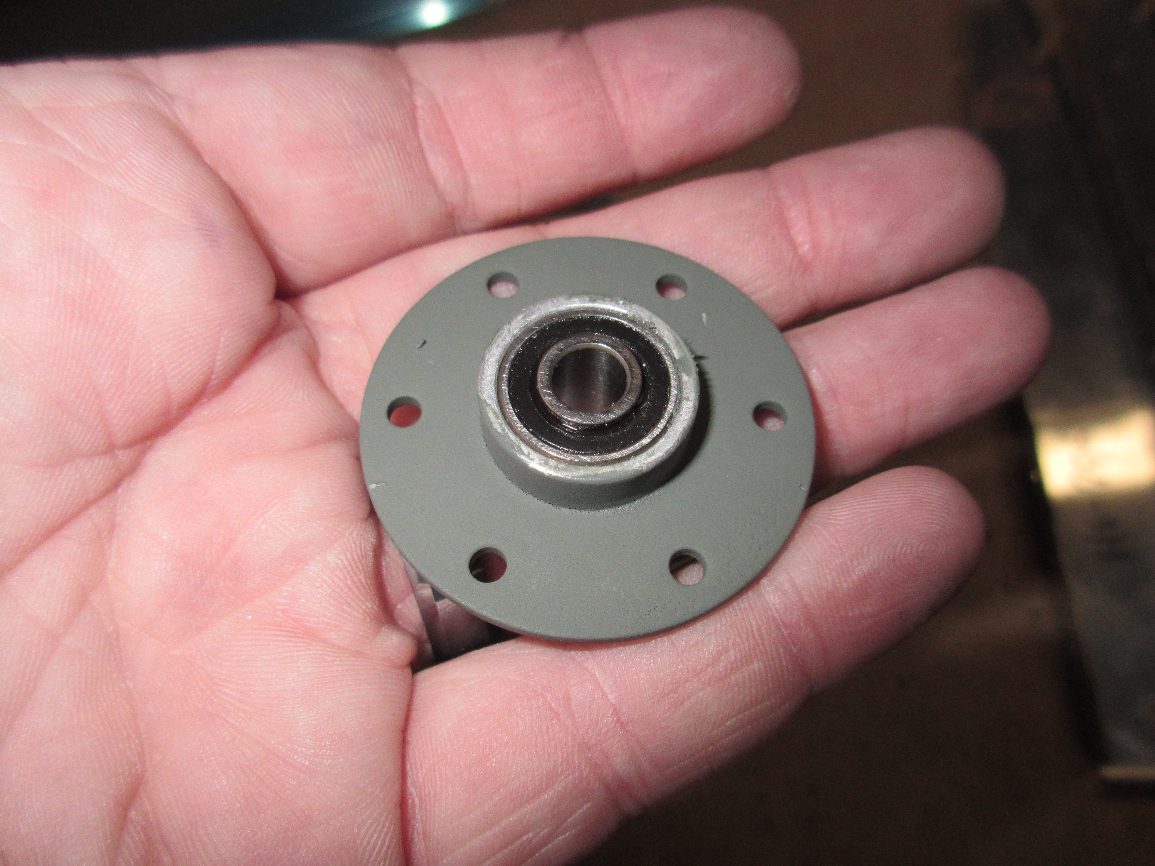
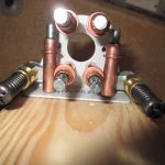
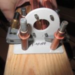
Some last few steps: After letting VS-146 dry, I noticed I was a bit light on my primer and missed the bearing housing a little. So I gave it a second light coat with the part on an angle to cover the sides of the bearing housing. I’ll let it dry overnight before assembling it.

The next section of the plans was “preparing the ribs” which was really only two easy little steps, so I figured I would go ahead and knock it out while I was in the mood. I fired up some Blackberry Smoke to listen to, and prepped some metal!

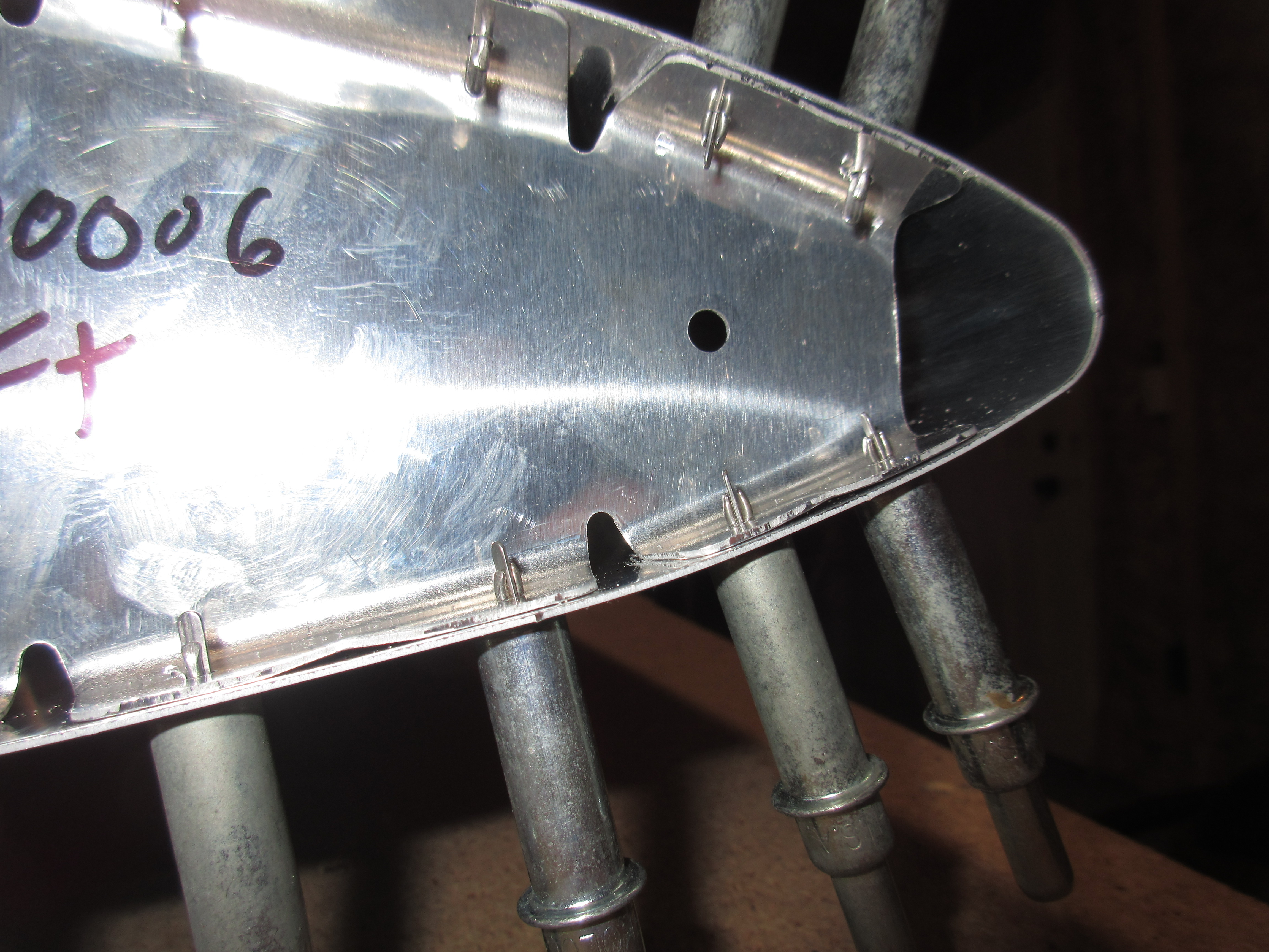
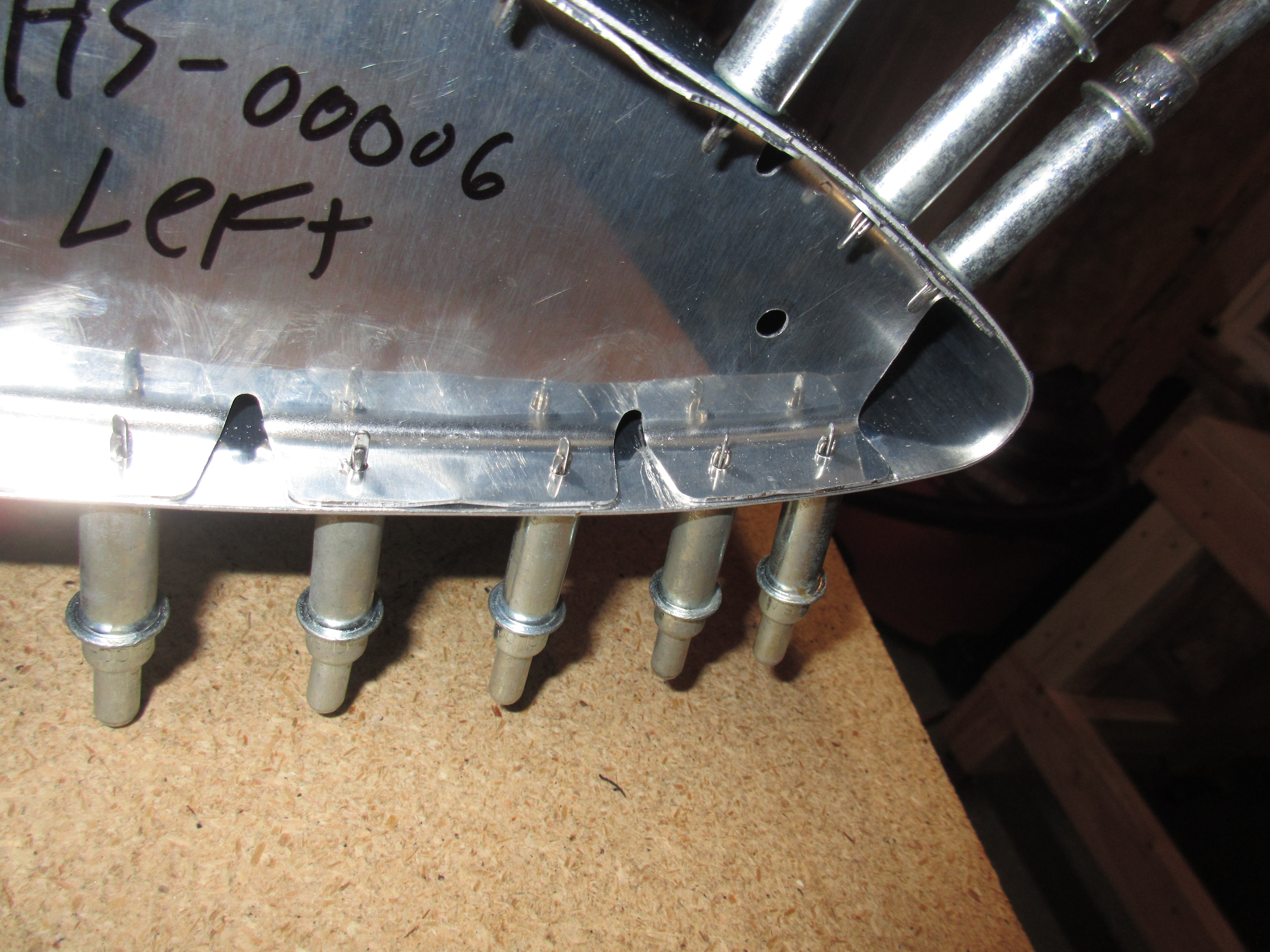
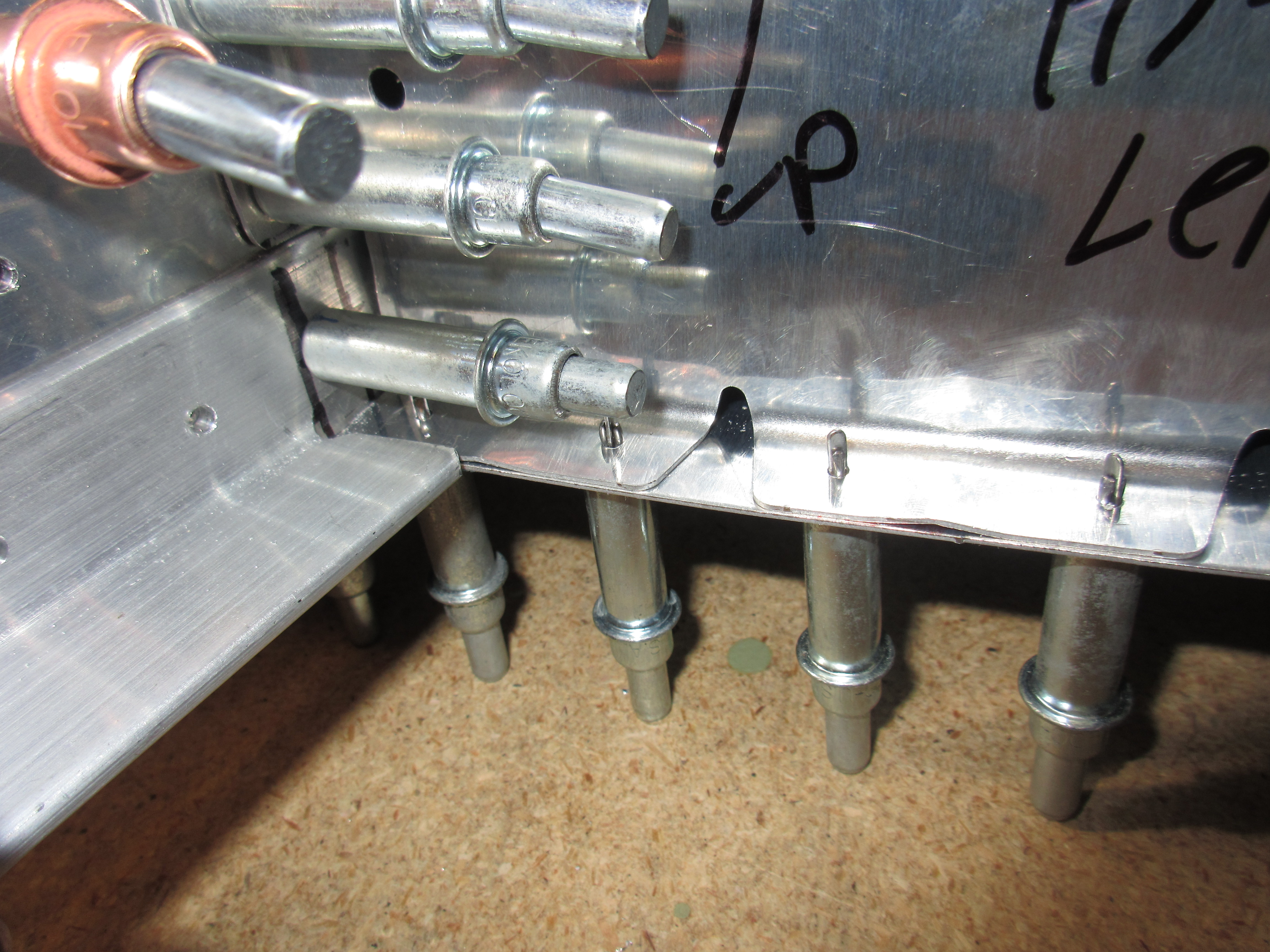
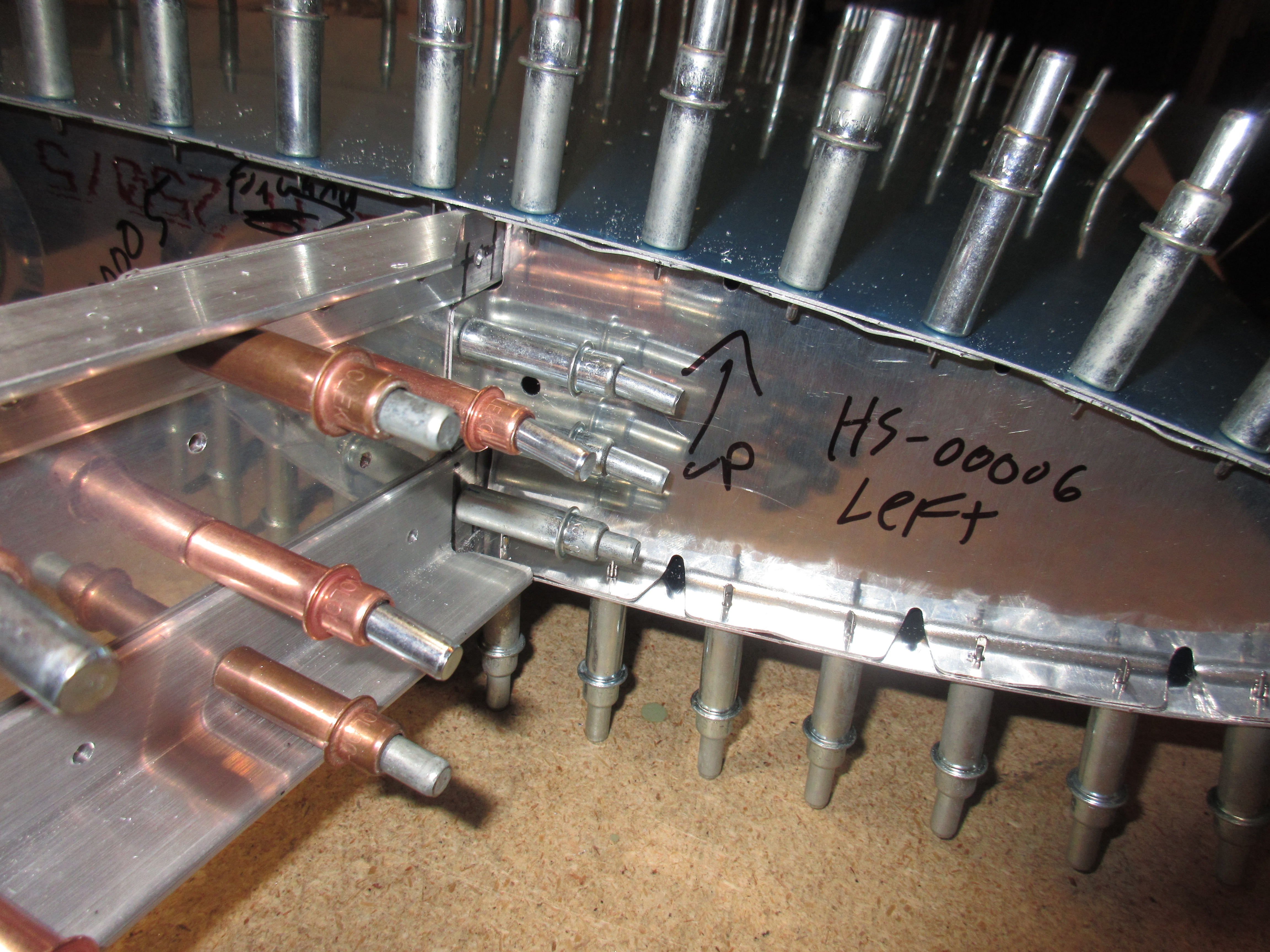
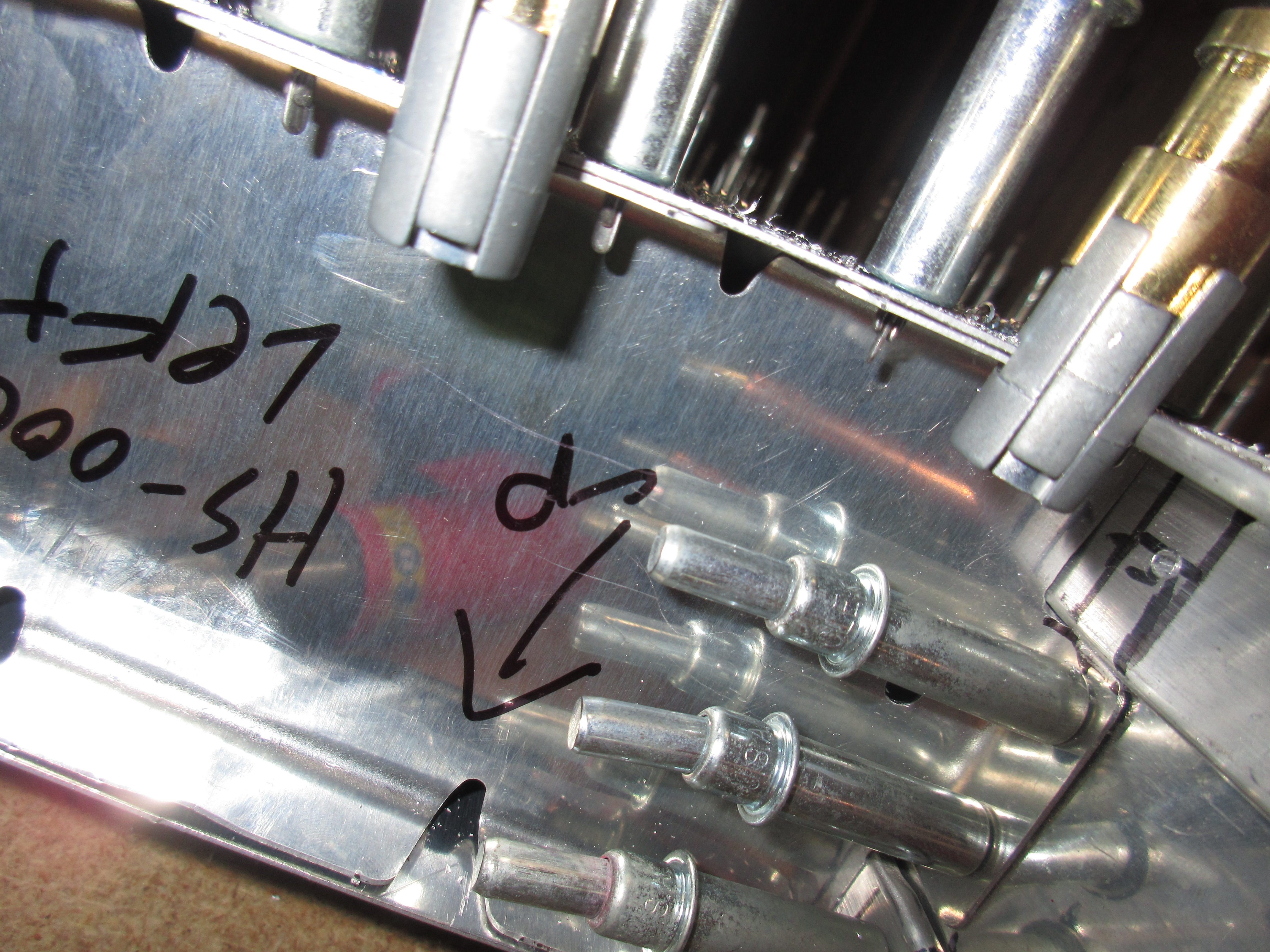
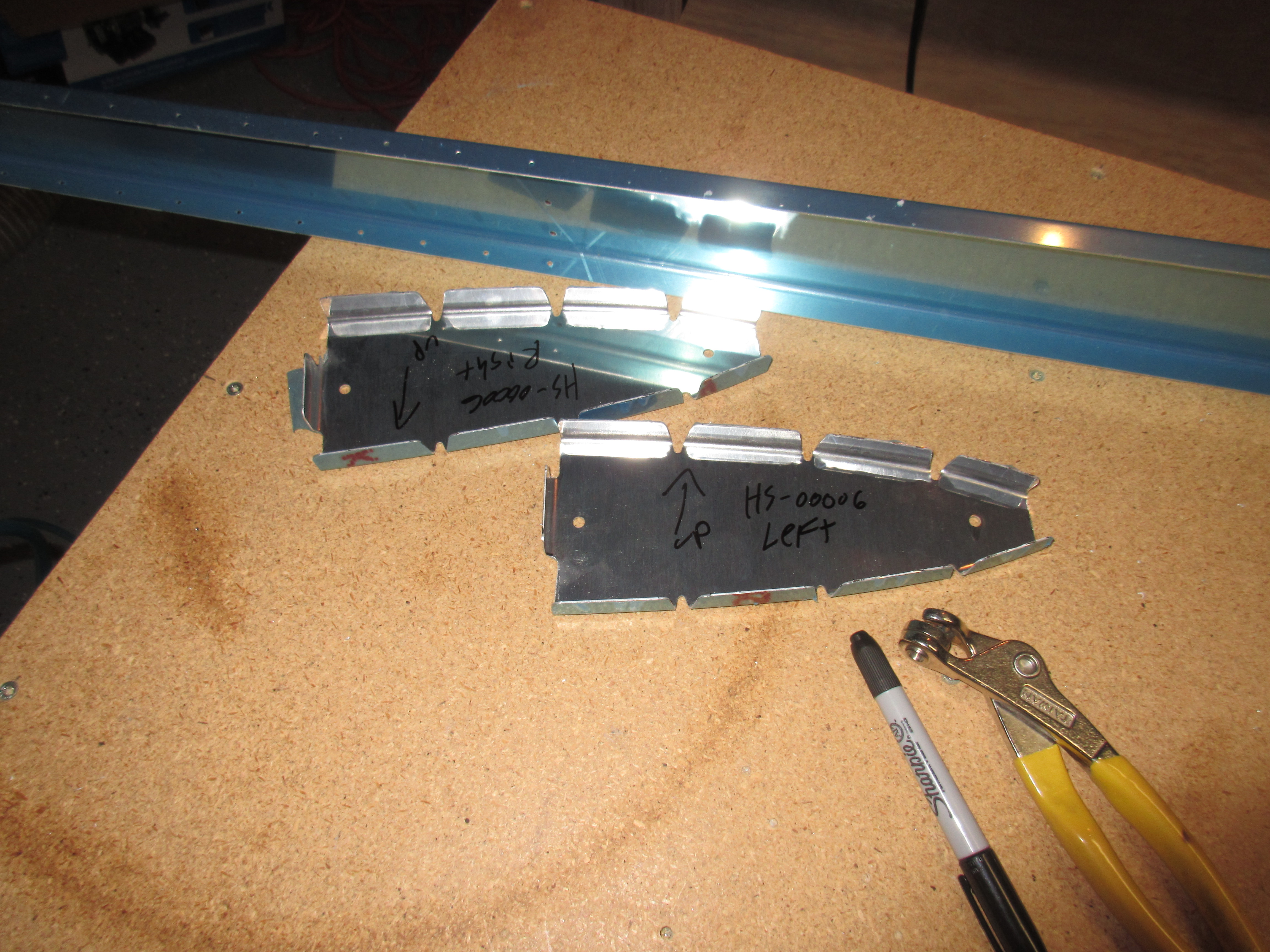
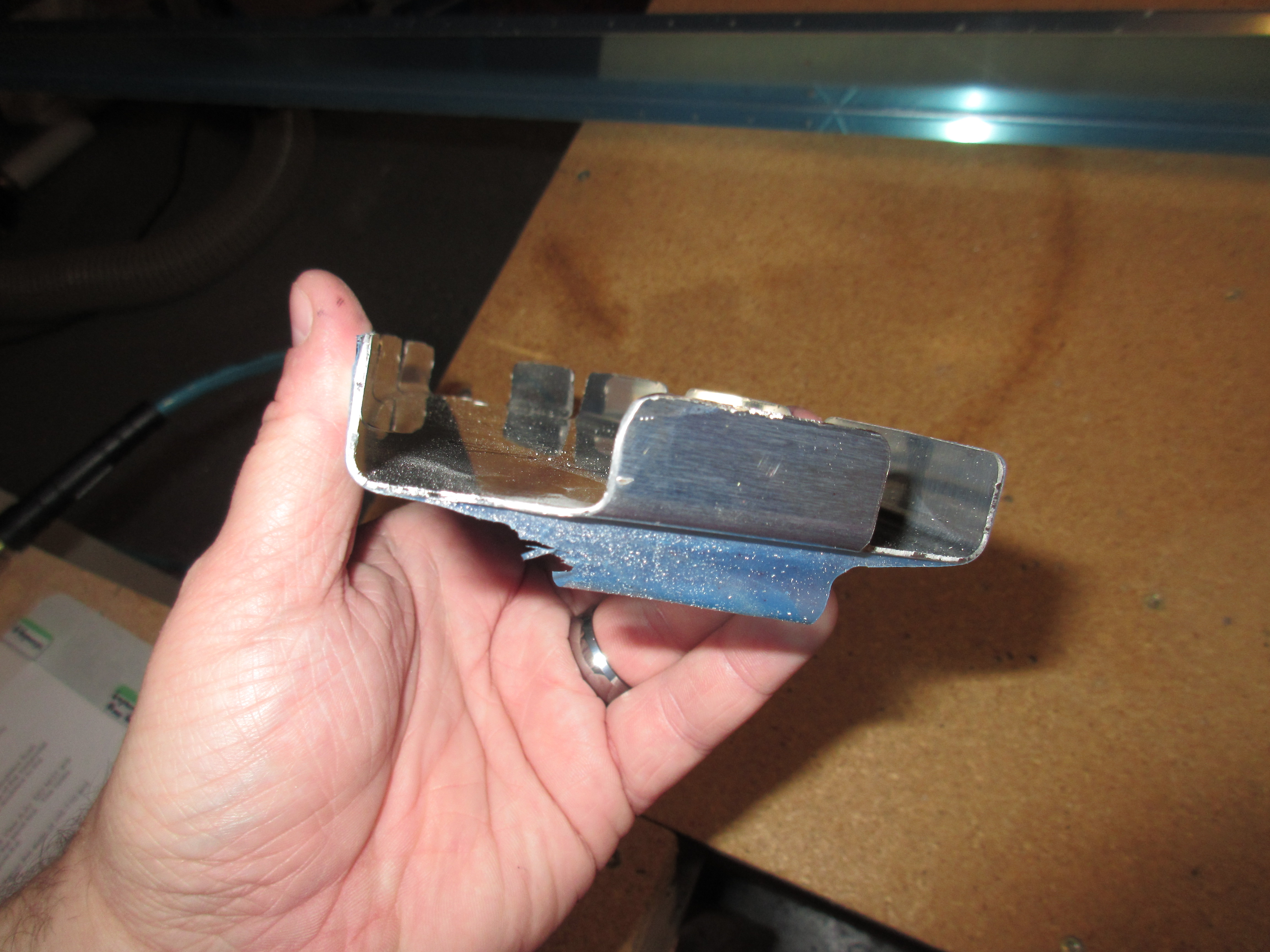
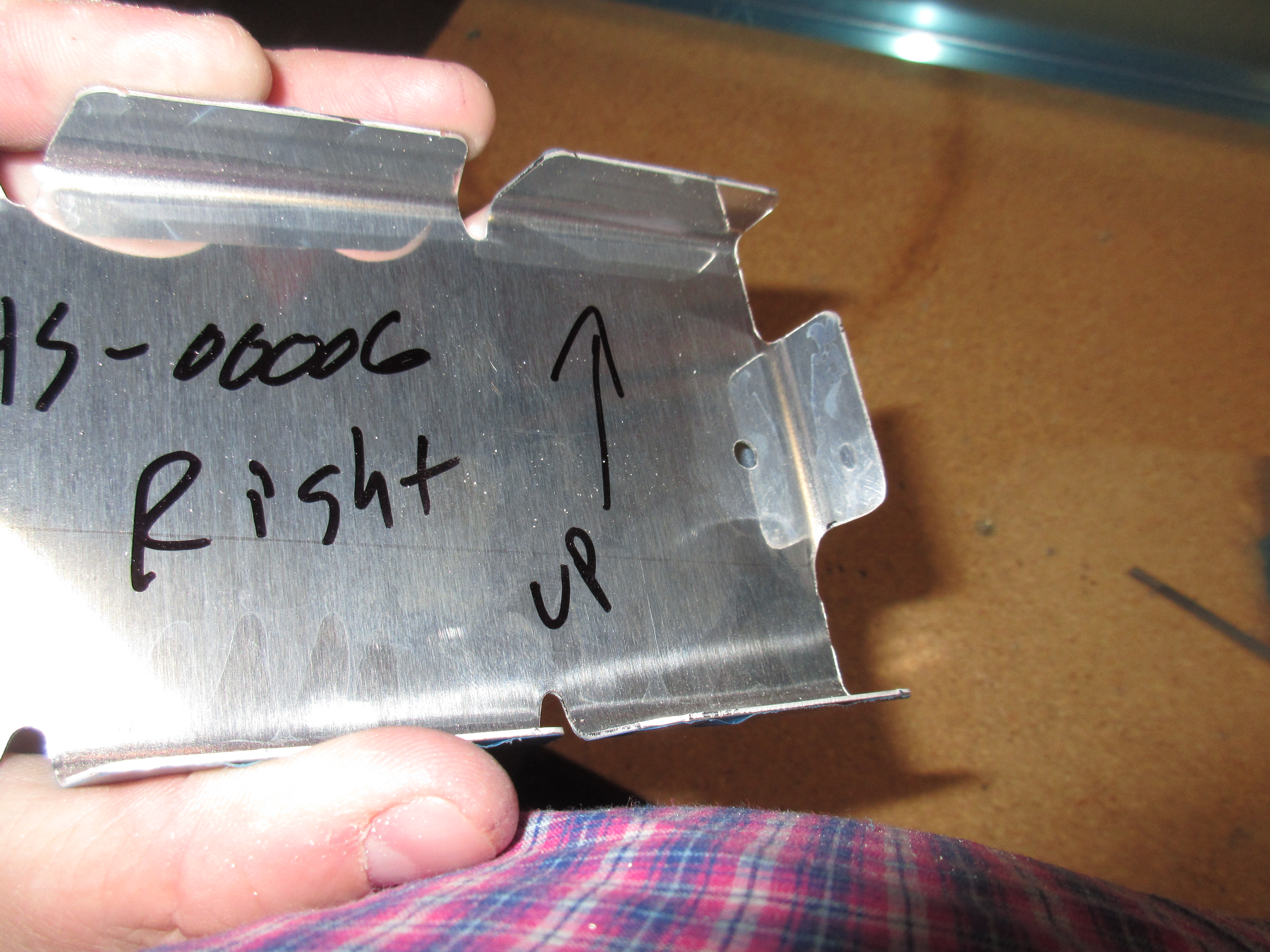
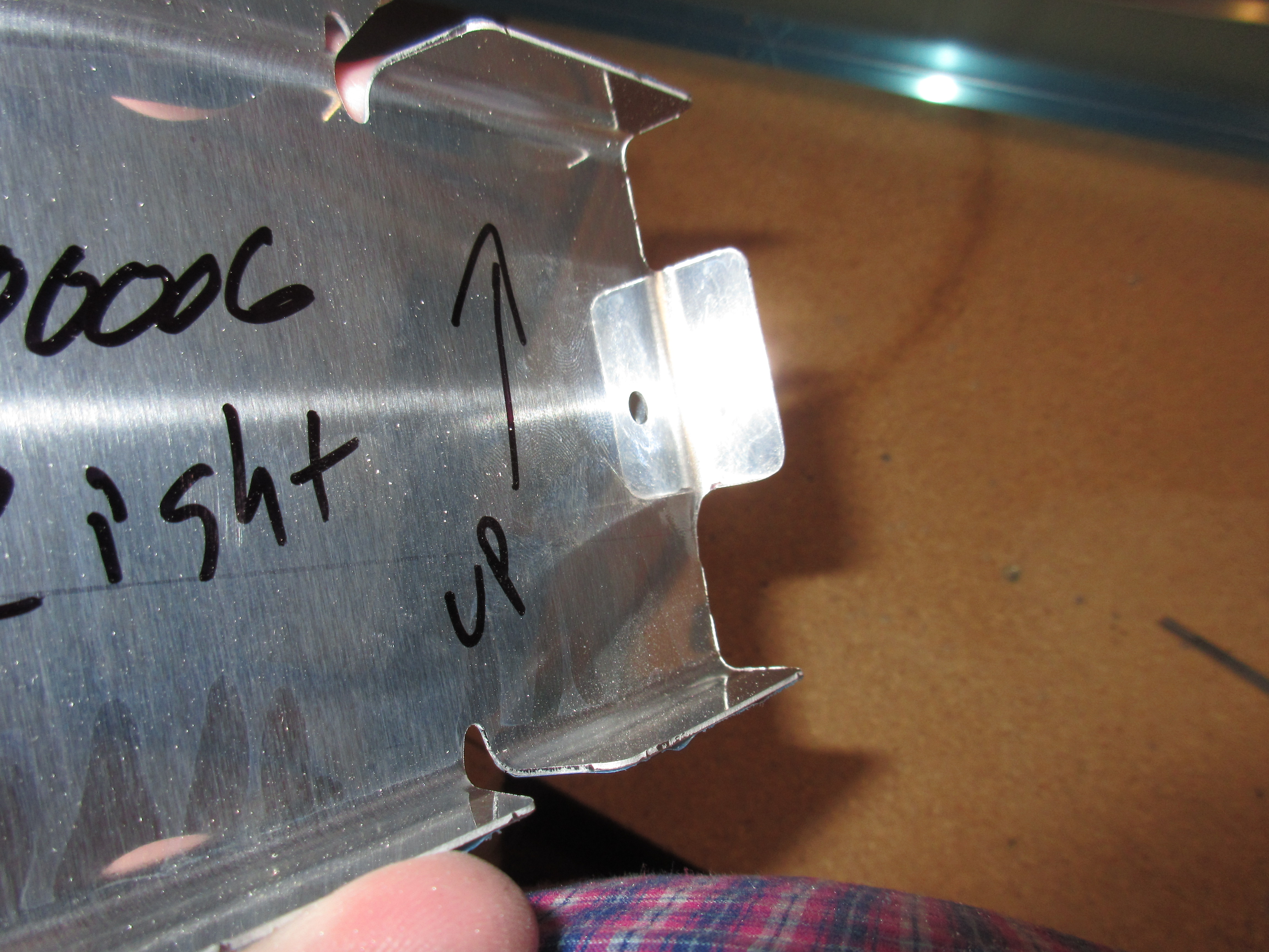
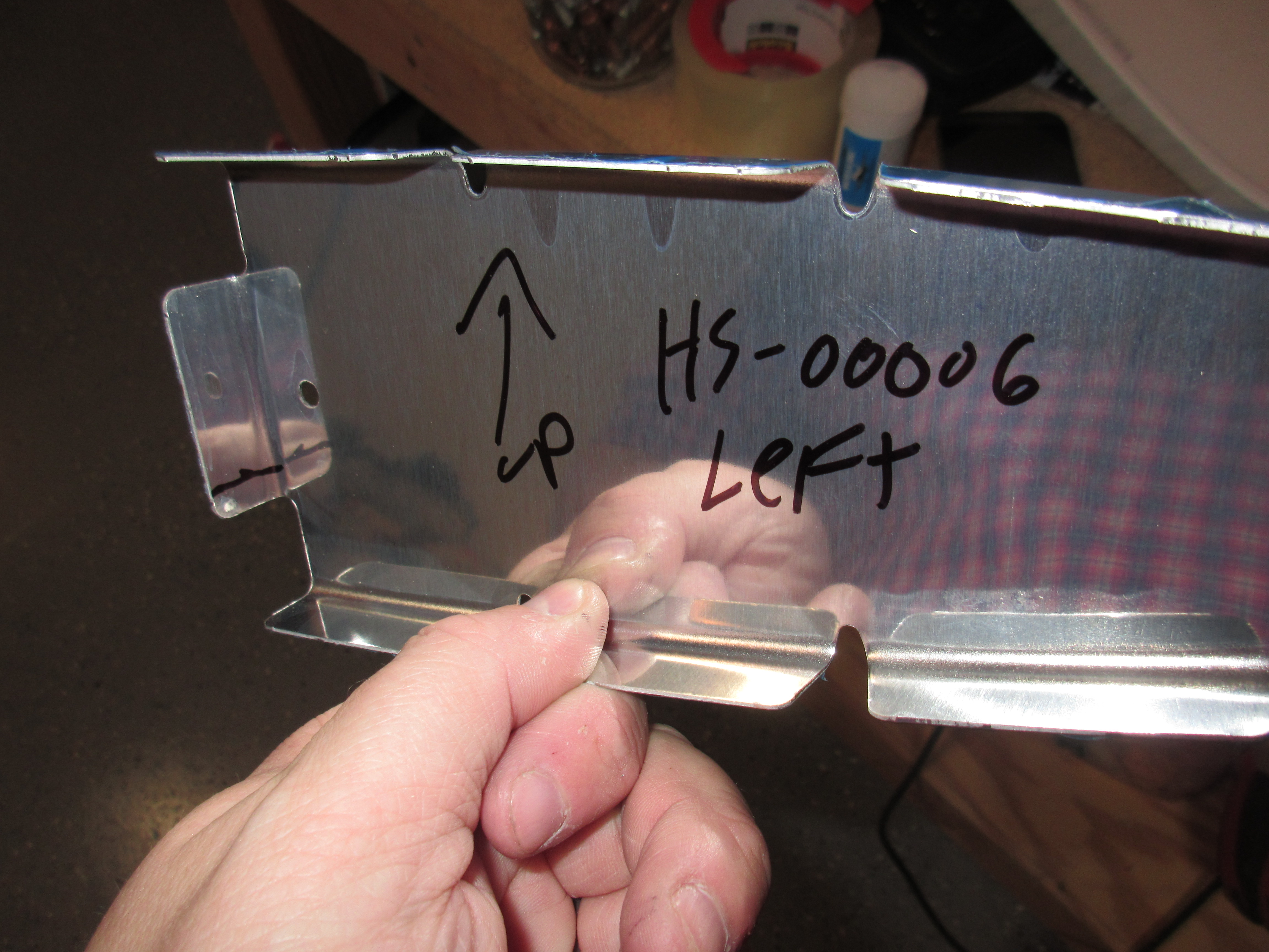
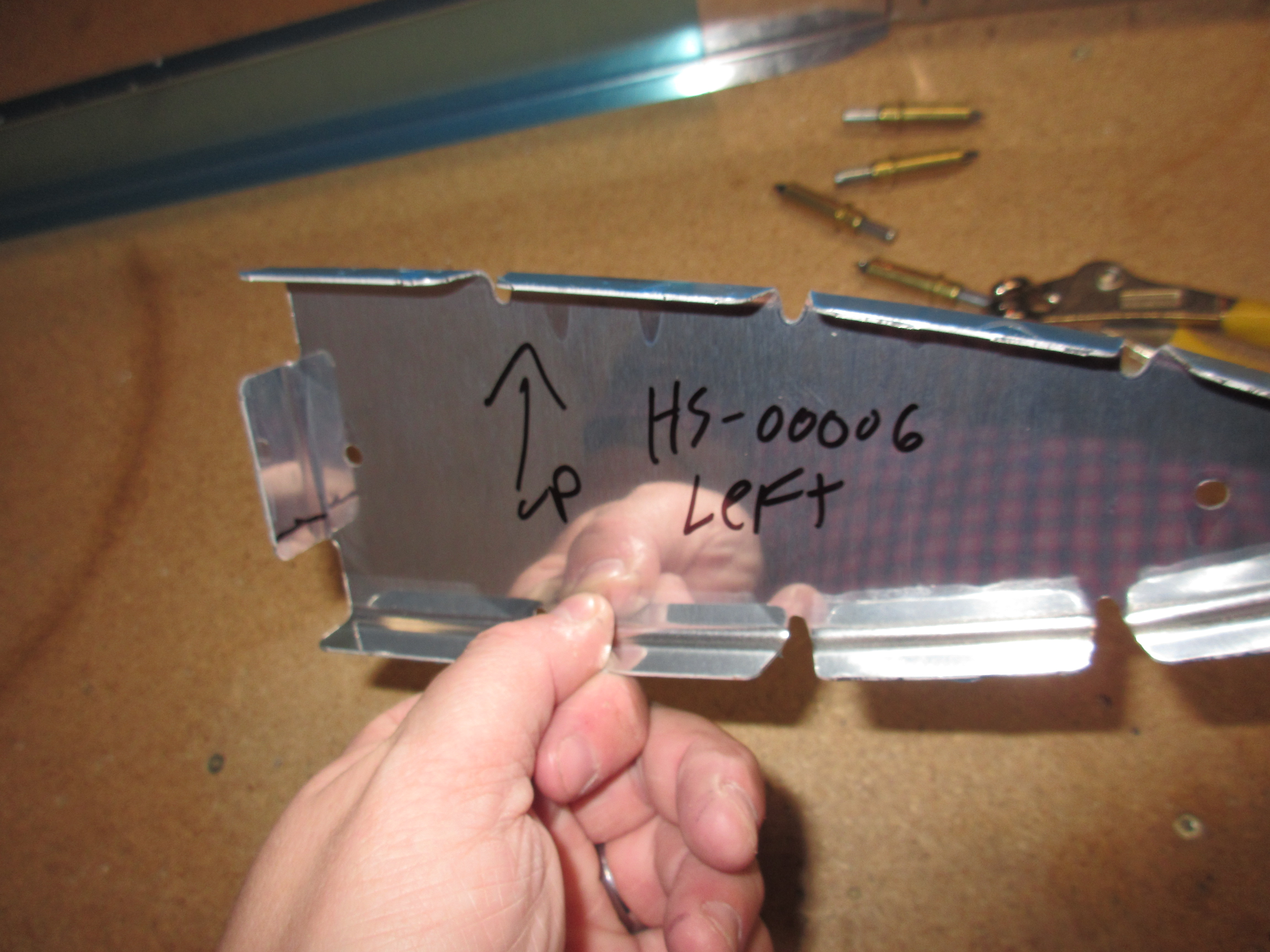
I trimmed both HS-00006 parts making sure to take note of left / right orientation and then marking accordingly. If you are reading this and are on this step, make sure you double check the orientation on the plans!!! After smoothing out the edges I moved on to the others.

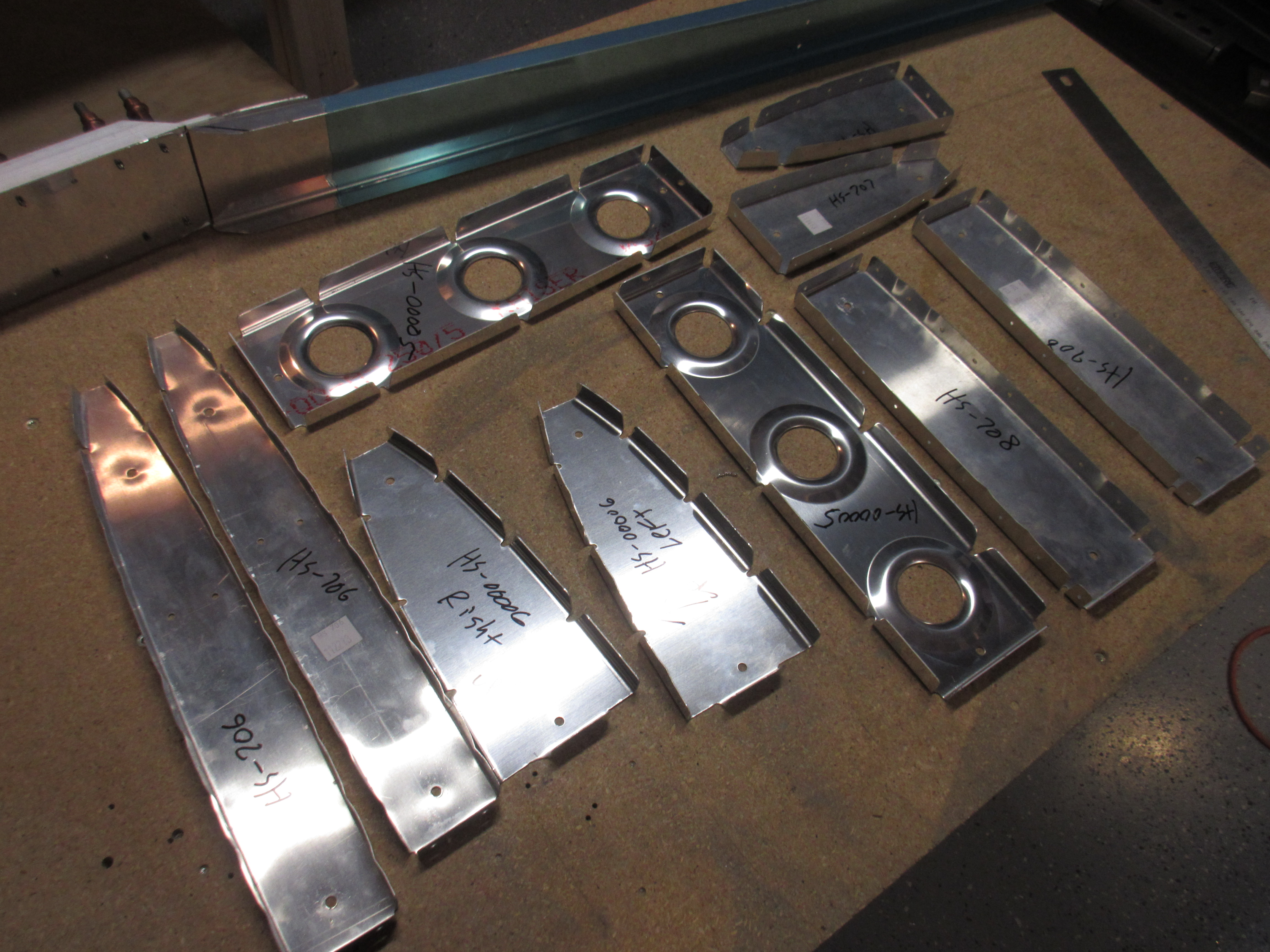
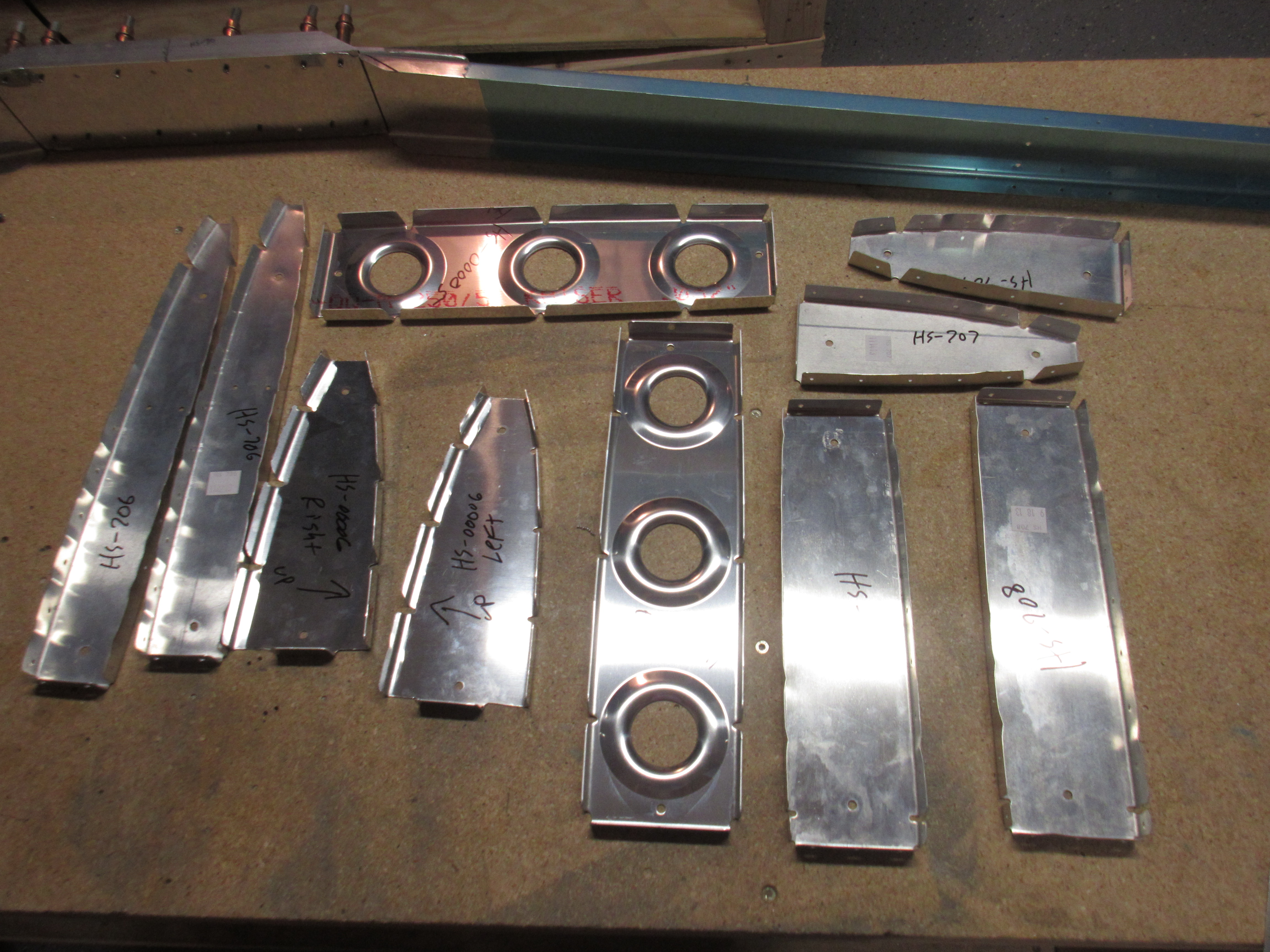
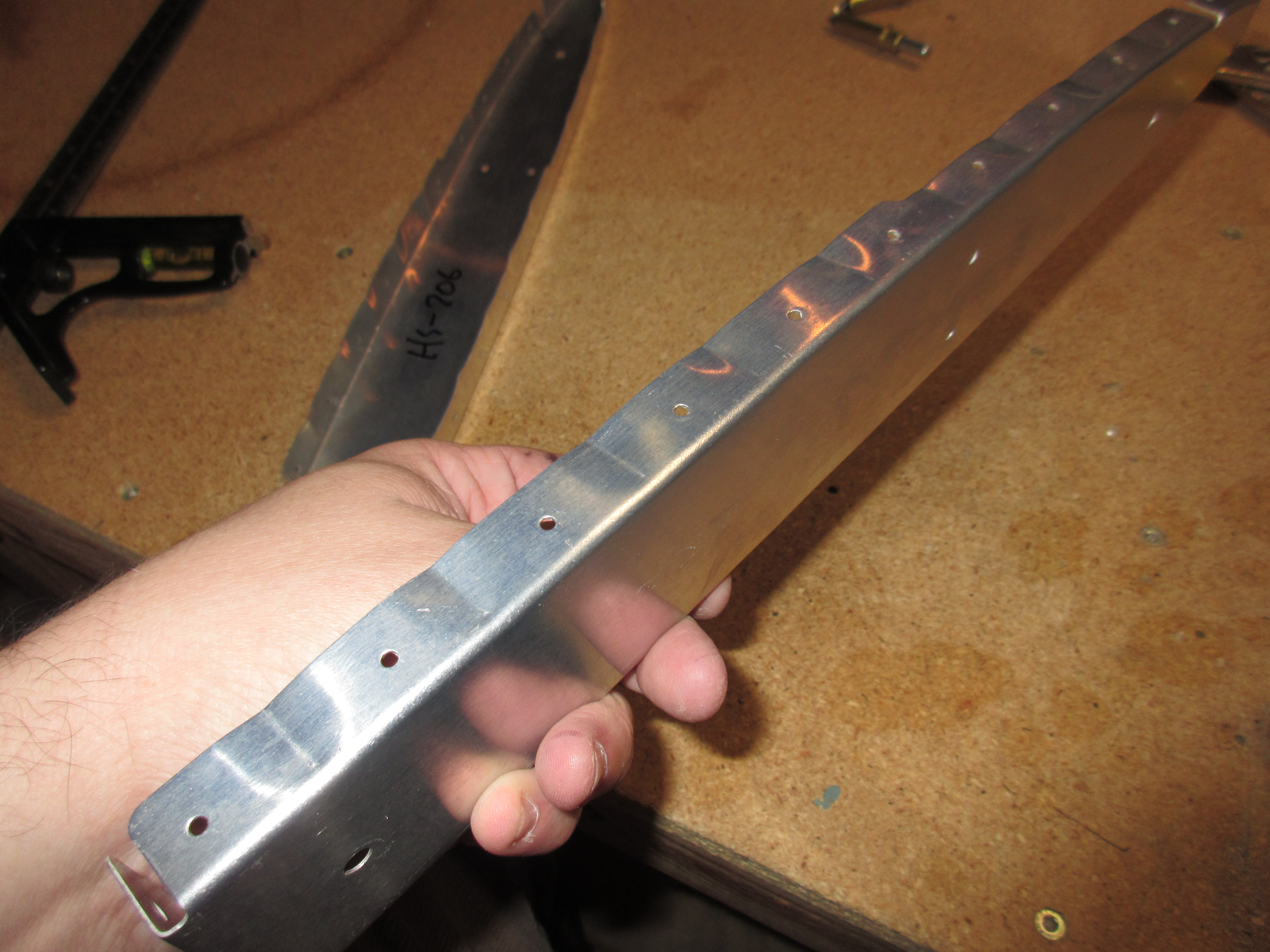
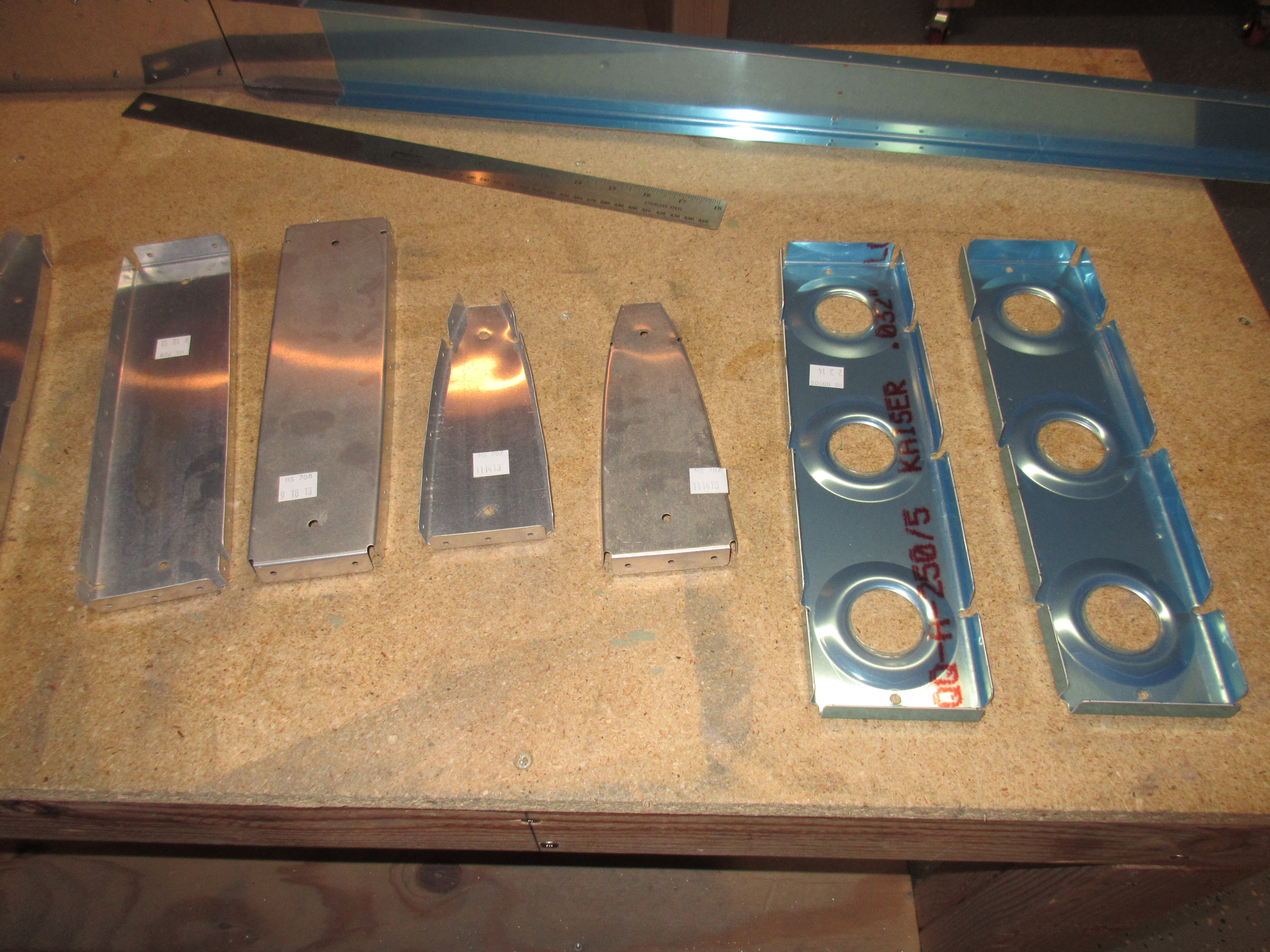
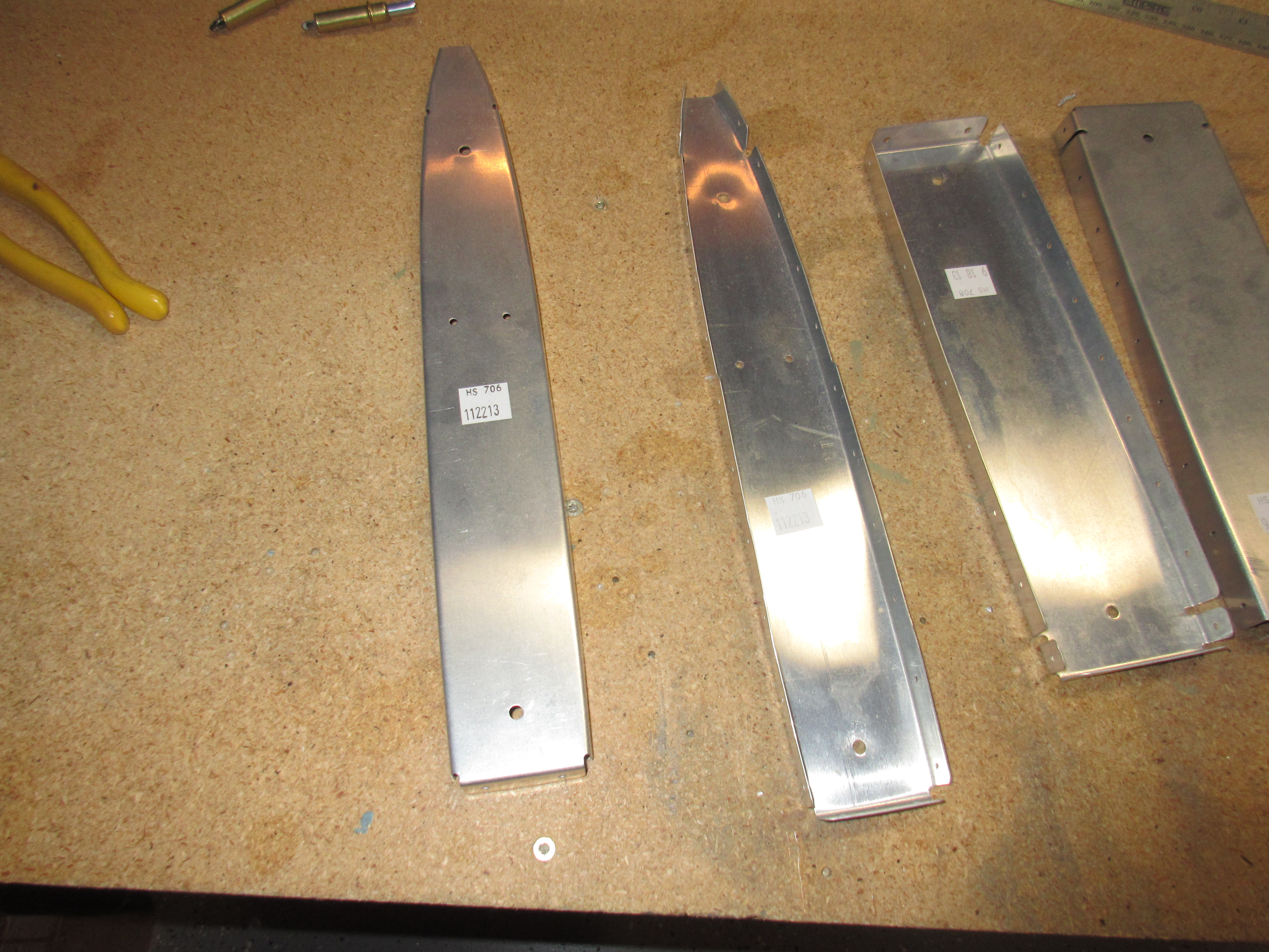
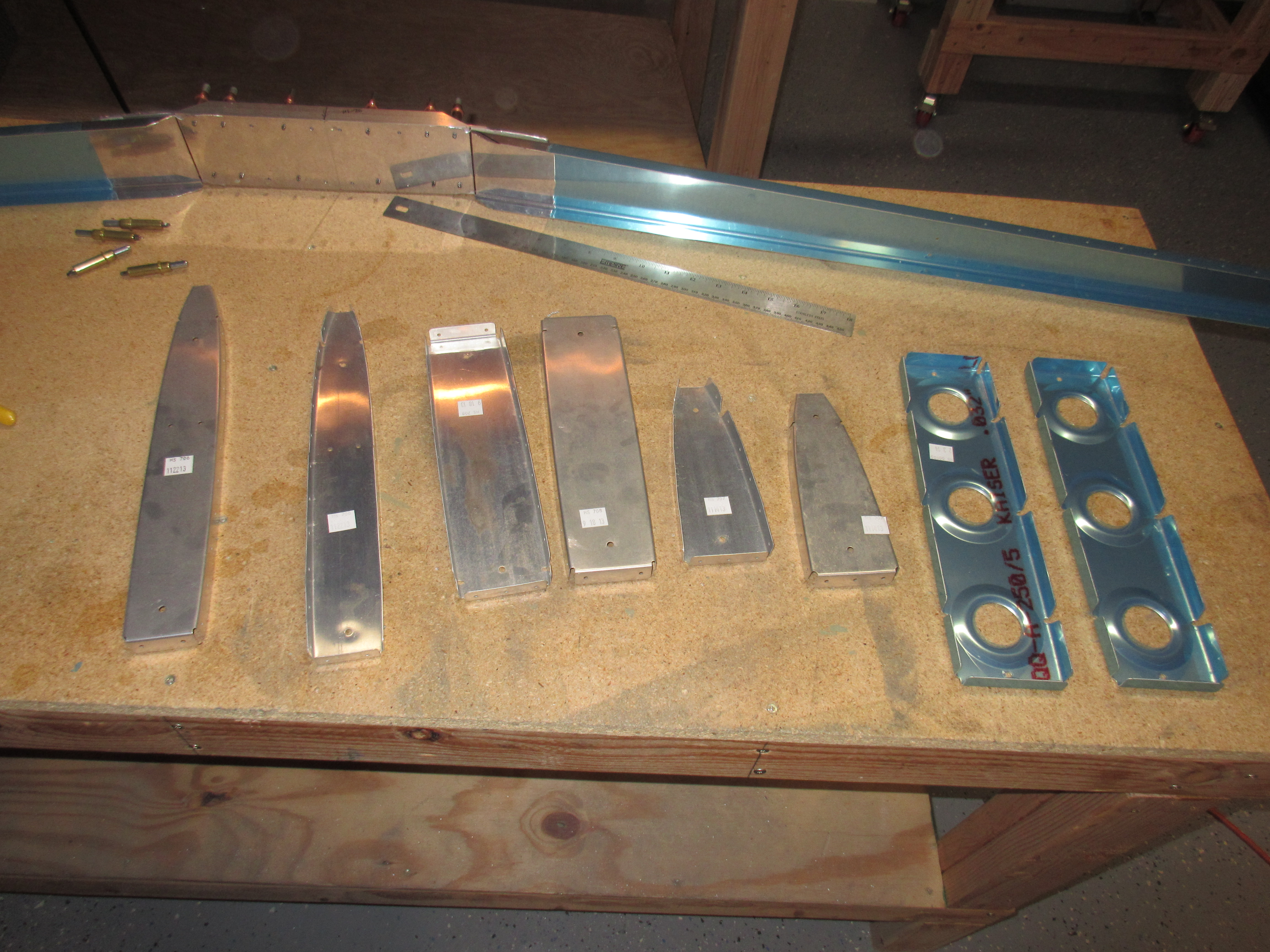
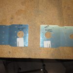
I picked parts (2 each) HS-00005, HS-706, HS-707, and HS-708 from their shelves and removed the blue plastic from them. I have read leaving the blue plastic on parts that will be mated together is not a good thing because it affects your measurements. These are all internal parts that I am going to be scuffing and priming anyways so it wasnt needed anymore. I used a 90 degree straight edge combination square to make sure all the flanges of each part were at a true 90 degrees. Some were pretty good, others needed a little tweaking with my edge seamer. Then I moved on to fluting the parts. These parts are fairly complex punched parts and due to the nature of press punched parts sometimes they are “warped” as slight degree. I laid them on my bench (both sides of them) to check their flatness. If any were not flat, I would make a couple of flutes and re-check, repeating the process until they were laying flat and true. Once I had a part trued and flat I marked its part number in sharpie and laid it back on the shelf. Some parts only needed 1 or 2 flutes, others needed more. I was happy with how they turned out. I will leave the deburring, edge finishing and scuffing until I get ready to bundle all the parts together and prime them.


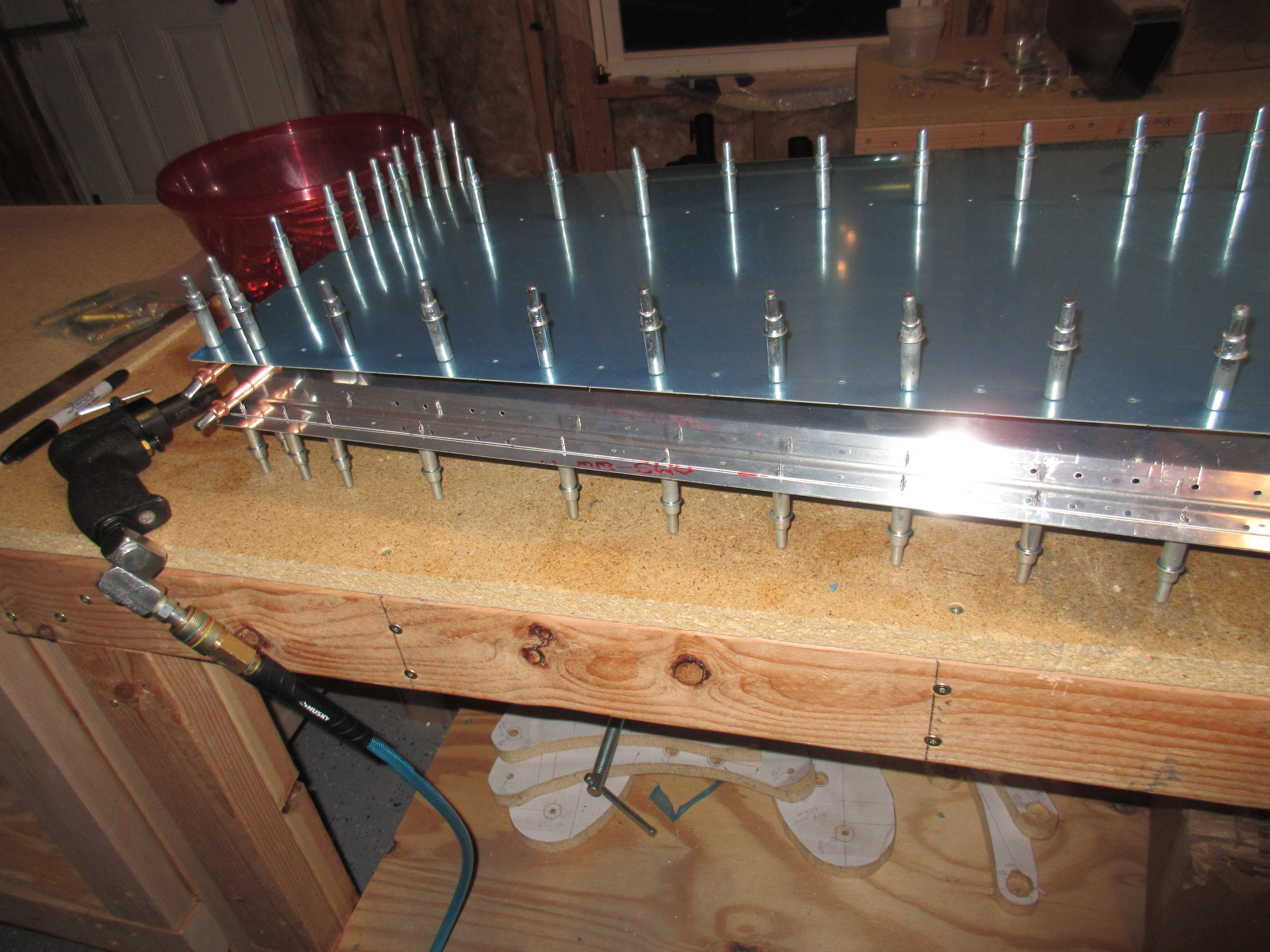
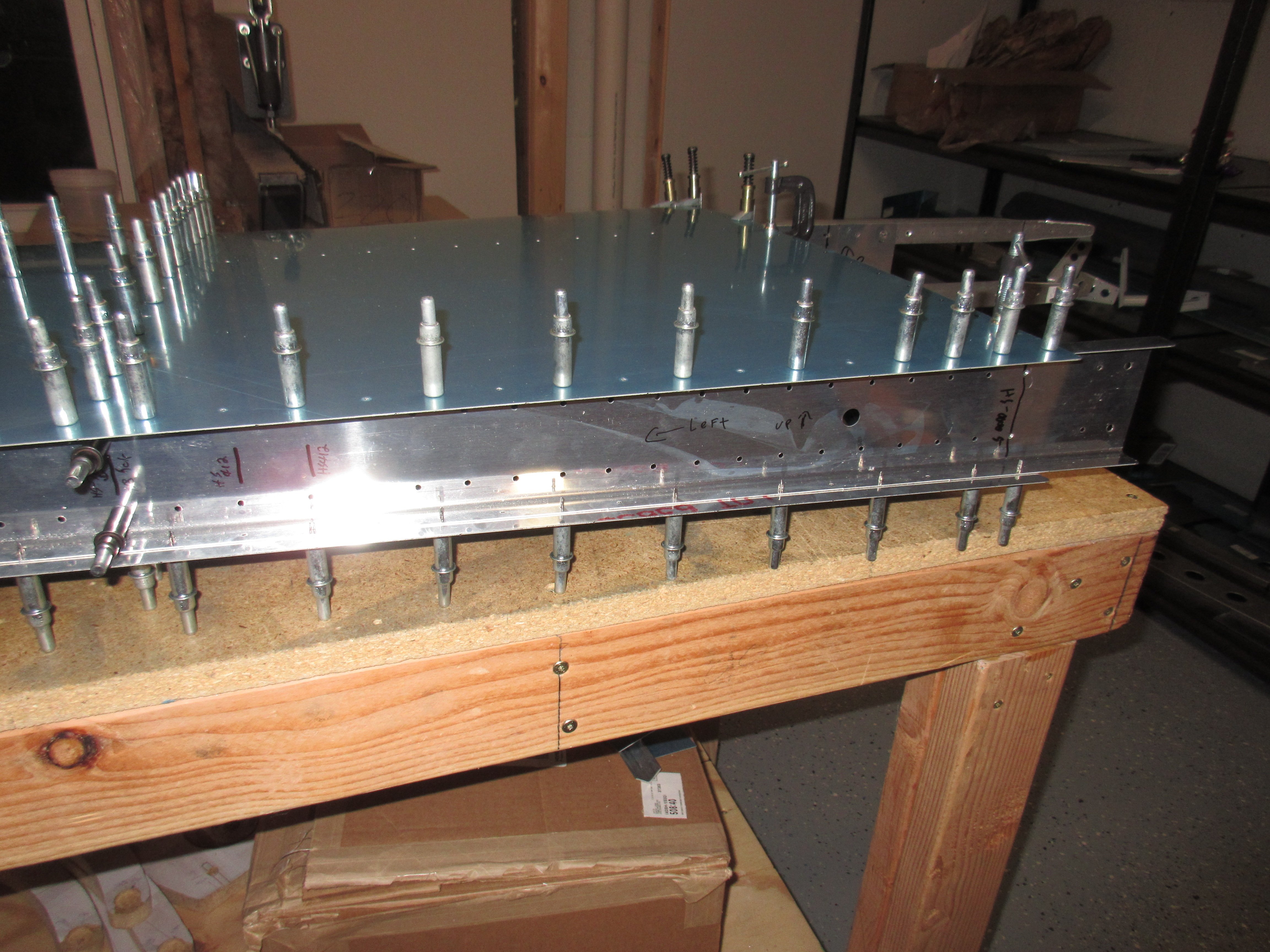
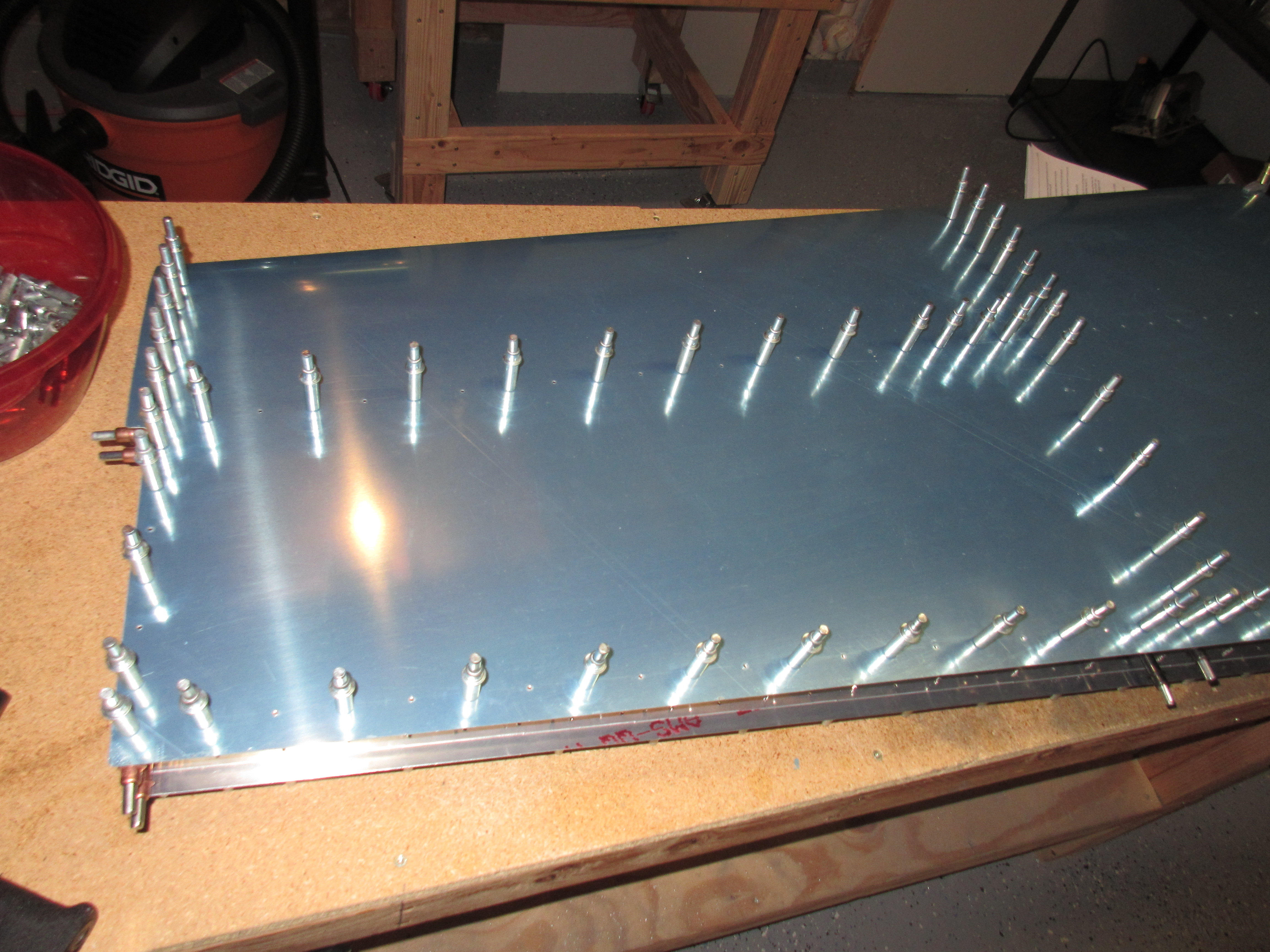
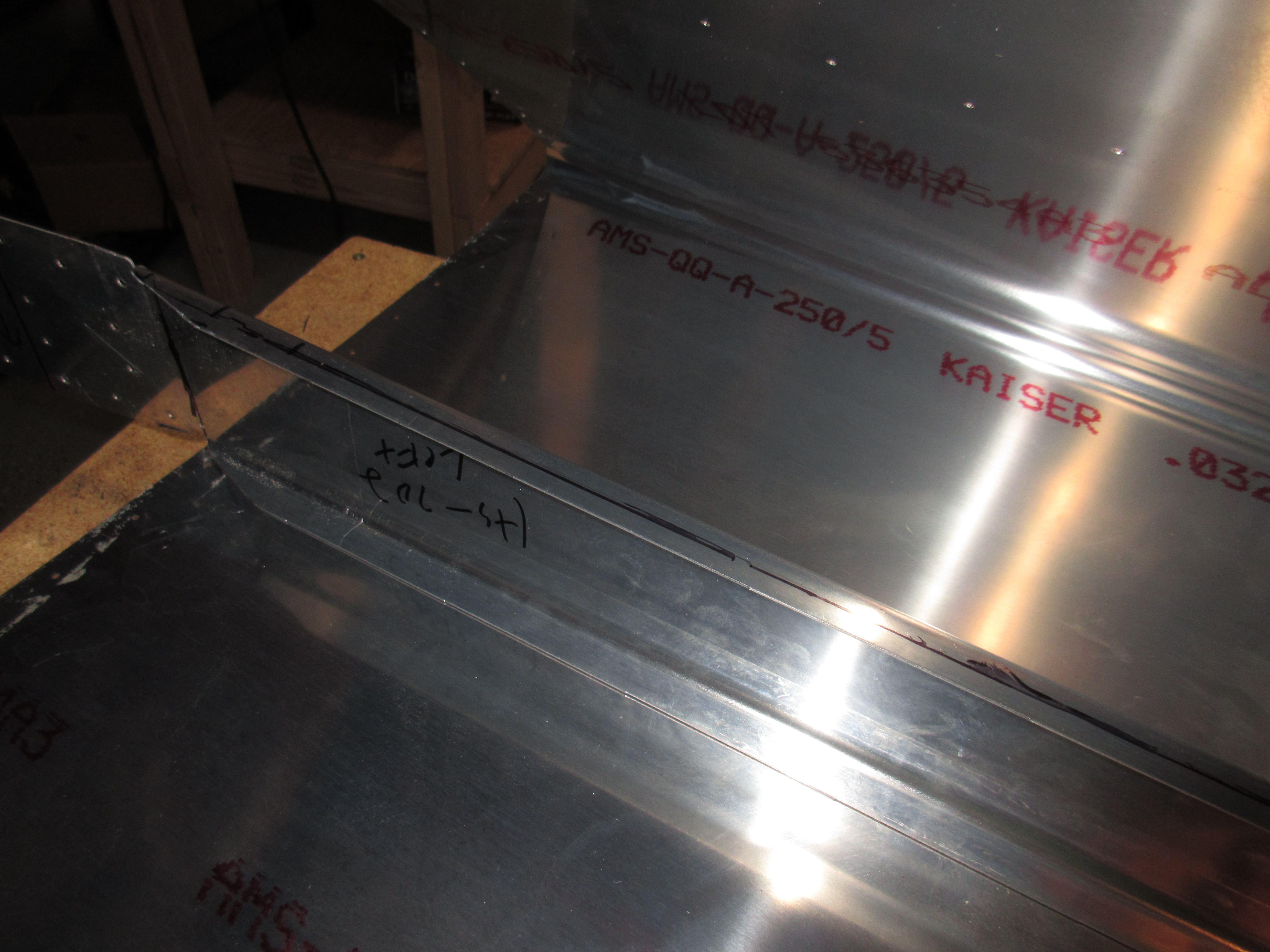
Here are the photos from tonights work: https://goo.gl/photos/o96i7MN8sSrisw2H7


Hours Worked: 4.5

Front Spar Assembly

Today I started the “Front Spar Assembly” of the tail kit. After feeling good about the rear spar, I figured this would be just as easy. That wasn’t the case.

I spent much of my time just looking at the planes and holding parts together to visualize what was needing to happen. 3.5 hours of work later and I didn’t really have much accomplished on my bench. I separated the doubler plates and cleaned their edges. This was required by Vans Service Bulletin 14-01-31. My kit came with these parts already which was nice.

I also measured and marked the bend lines for the spar itself, but will wait until the next session before bending. I want to make sure all is correct before I proceed, and I have fresh clear mind. Thats all for today, 3.5 hours of fiddling around.

Here are the photos from the nights work: https://goo.gl/photos/PVqvHELHftMQZQ7A7


The Journey begins!

Like every journey starting with the first footstep, I started my journey on the rear spar, like so many others who have gone this way before me.

I worked a solid 2.5 hours tonight. I didn’t want to push myself to do to much in my first session, and really wanted to just dig in and start cleco-ing stuff together to help motivate me.

Tonight I completed all the steps for the “Rear Spar” section of the first page on the plans. I found that using my bench grinder with a course wheel made quick work of the thick HS-609PP reinforcement bars. I had to break the edges and then taper the ends off. I rough outlines my shape with a sharpie and used the course wheel to work the metal down to the marks. Once i was happy with the rough shape, I used my file and the scotchbrite wheel to smooth the edges. I really like that scotchbrite wheel, its a great tool.

I am leaving the flat surfaces unfinished for right now, so I highlighted that step in my plans so i don’t miss it. I am going to prime the interior sections with AKZO, and I am going to try to consolidate all my priming so I will leave the surface as is, until priming day.

I made sure to mark that 8th hole on each side where HS-708 will attach so as to not rivet it by accident.

Then I moved on to building the HS-411PP bearing assembly. I actually picked up a good trick from George Ordorffs videos of drilling the VA-146 bearing assembly. I clamped HS-411APP and HS-411-BPP together u

sing cleco clamps. The I clecod those two down to a 2×4 block. I used BPP as a drill guide for APP and clecod to stabilize as I worked my way round. Once it was done, I test fit VA-146 between them and it fit beautifully. Deburr’ed the holes, and then sprayed VA-146 with some rattle can self-etching primer after I gave it a good roughing and cleaning. I will let it sit overnight to dry before riveting this assembly together.


Here is a link to the photos from tonights work: https://goo.gl/photos/Pk6pCY4hnbneTEA17

Hours Worked: 2.5