Finishing the Rudder Stiffeners

Tonight I finished up the rudder stiffeners.  I filed down all the corners and smoothed the edges down.  After that I ran them over the scotchbrite wheel to get the edges completely smooth and burr free.  Once I had the edges and corners took care of, I moved on to deburring the holes.  I finished all 16 stiffeners, 8 for each rudder skin, tonight and put them on the shelf until I can prime them.

After that I removed the protective plastic from the inside of the rudder skins, and then a few strips along the outside where the stiffeners will get riveted. I’ll leave the majority of the plastic on the outside surface to protect the skins until painting, sometime down the road.  I’ll prime the interior side in a few days.

Once I had the plastic removed, the skins are ready to be deburred and dimpled, along with the stiffeners.  I’m holding off on the dimpling until I get the skins and stiffeners primered, then I’ll deburr and dimple.  The skins went back on the shelf until priming time, and that was it for this session. Here’s the photos from this session:

Google Photos Link: https://goo.gl/photos/FTb5cd7oJkv4A7fB7

Hours Worked: 2.5

Fitting the Stiffeners to the Rudder

I started on the sections of the plans labeled “Building the Rudder” and more specifically, the sub-section “Fitting the Stiffeners to the Rudder”. The rudder is made of thin .016″ aluminum, so Vans uses tiny L-shaped brackets called stiffeners to help support the skin, and keep it from wobbling.  In the kit, these are parts that you have to fabricate a little.  The kit ships with 8 pieces of L-shaped aluminum that you have to trim into the shape of a stiffener.  The plans has the dimensions, and there are some notches in the stock to help you align your cuts.  I used my bandsaw with a metal cutting blade to make the cuts instead of using snips. Here is what the stock looks like:

And here is what it looks like after you rough cut the two stiffeners from one piece of stock:

After we have the stiffeners cut from the stock, we have to trim 7 out of the 8 per side to fit the rudder because it gets smaller towards the top.  In the RV-7, Vans has made this really simple: You cleco on the stiffener and then mark the hole on the forward edge that is the closest to the spar, and then trim off the excess.  It’s important to note in the plans, that we need to leave a 1/4″ edge distance from that hole which I did.  I then used the non-trimmed stiffener as a template to mark the cuts for the end angles.  Repeat this until you get 16 stiffeners and you are good to go!

Next up was to cleco the stiffeners to the skin to match drill.  I started with the left side, marked my stiffeners and skin and then match drilled them right down into a sacrificial piece of particle board to hold everything secure. I did the same to the right side.

After everything is match drilled, I disassembled everything so I could prep the edges and debur the holes.  This is going to take some time, so I only started on the left side stiffeners.  I was able to round off all the corners of the stiffeners, as well as knock down some really rough edges.  All 8 of the left stiffeners are ready for deburring, and then a trip on the scotchbrite wheel to smooth them out.  But, thats work for another session, I have already put in 4 hours tonight cutting out the stiffeners.

Here is all the photos from tonights work:

And the link to the Google Photos: https://goo.gl/photos/1RtwoBeyMD8rGqJo7

Hours Worked: 4

Assembling and Riveting the Vertical Stabilizer

Tonight I worked about 4 hours and completed the Vertical Stabilizer, except for the rear spar, which I am leaving off until the EAA Tech Counselor can come by and take a look at my work.  This will give them access to view and check my riveting and assemblies.  Once they sign off, I will rivet on the rear spar to both the Vertical and Horizontal stabilizers.

I started off tonight by assembling the skeleton for the vertical stab but clecoing VS-704, VS-705, VS-706 and VS-707 ribs to the front spar, and making sure everything still aligns correctly.  I temporarily attached the rear spar to double check, and then remove it to continue on. Then I riveted on VS-706 and VS-707 using AN470AD4-4 universal head rivets. I used my squeezer on them to set them perfectly.  BUT, VS-704 and VS-705 end ribs were a COMPLETE pain in the butt! The plans calls for a AN470AD4-5 rivet to hold these two ribs with the VS-703 front spar sandwiched between them.  The rivet was a little long, but I trusted the plans.  I could not get my squeezer in there so I had to buck them.  However, I could not use a standard AN470 rivet set, because the ribs did not have any clearance even if I flexed them out of the way.  I had to use an offset head, and ended up folding a couple rivets over.  After drilling out a couple of rivets, I FINALLY was able to get all three of these buggers set correctly.  After reading on Vans Airforce, a lot of builders have trouble with these suckers, so I’m not alone 🙂  Heres what the skeleton looks like after it was all riveted:

Once the skeleton was done, it was time to cleco on the skin and make sure it was lining up correctly.  This was about the time I realized I hadn’t dimpled the skin yet…whoops. heh.  So, I rolled the DRDT-2 over to the bench and spent the next 15 or 30 minutes dimpling the skin. Before dimpling, I made sure to tape up the holes along the root that are marked in the plans for nut plates to hold the fiberglass fairing in the future.

NOW, I can finally cleco the skin to the skeleton and get it ready for final riveting. I clecoed every hole on both sides because this is a large surface with some complex curves around the leading edge.  I figure a little extra work of clecoing will pay off when the results are smooth and oil-can free. After the skin was clecoed fully on both sides I begin to rivet it down. The plans has us start out at the intersection of rib VS-707 and work towards the top along VS-702 front spar.  This first rivet is a little longer due to the converging ribs, but thats the only one.  All the others were a AN426AD3-3.5.  After working up the spar to the top, I came back and worked toward the root along the front spar, alternating to the VS-707 center rib.  This is to get the skin down flush and prevent pillowing or oil-canning.  Once all the rivets were driven along the ribs, it was time to squeeze the ones along the end ribs.  I started on VS-706 and the leading edge and worked toward the trailing edge, and did the same thing with the VS-704 and VS-705 root ribs.  Once I had the left side done, I flipped it over and did the same to the right side. I am happy with the results! There’s no dents, dimpling, smiley’s or oil canning. This thing will paint up nicely along with the horizontal stabilizer.  If I can keep this quality of work up, I might end up with a decent looking airplane!


After I got it all riveted up, I temporarily clecoed on the rear spar so I can hang it on the wall to keep it out of the way and safe.  I am going to round up an EAA Tech Counselor tomorrow and see if they can come out and inspect them.  Here’s all the photos from tonights work:

And of course the Google Photos album link: https://goo.gl/photos/z48dTJShJuPsuRUQ6

Hours Worked: 4

Riveting the Vertical Stabilizer Rear Spar

I worked about 2 hours tonight on the vertical stabilizer rear spar. I also spent a few minutes coming up with a way to mount my horizontal stabilizer on the wall to keep it safe and out of the way.  For about 2 bucks in hardware, here’s what I came up with:

img_0842

And it actually looks pretty decent against the wall.  At the very least, I will have some nice looking aviation related wall art 🙂

img_0841

After that, I continued on to working on the Vertical stabilizer.  Vans has us start on the rear spar of the vertical stab by clecoing on the Vs-803PP spar to the VS-808PP doubler, as well as the hinges VS-410PP, VS-411PP and VS-412PP.  I also taped off the holes where the VS-704, VS-706 and VS-707 ribs would rivet on later, so I didn’t accidentally rivet those holes.  img_0843

Once I had everything clecoed in place, and taped up, I was ready to rivet.  The plans have a myriad of different rivet lengths due to the thickness of the doubler, and the hinge plates so I started out by riveting on the VS-412 hinges at the top of the spar.  Once I had those on, I moved to the shortest rivet size group and worked my way up to the longest.  Eventually I had all the universal head rivets squeezed with my squeezer, and I could finish up with the bottom section of the spar.  This section I previously dimpled and countersunk because we need to use flush rivets on the face so that the spar will sit flush on the fuselage when we mount it.  So, I put my flush set in my squeezer, set the depth and set all those flush rivets on the bottom, finishing up my vertical stabilizer rear spar.  It came out looking really nicely!

img_0852

Here are all the photos from tonights work:

And here is the Google photos link: https://goo.gl/photos/JJZC2YV1fNmMq3mVA

Hours Worked: 2

Finishing the Horizontal Stabilizer Skin

I was able to finish up riveting on the skins of both sides of the horizontal stabilizer.  I had only planned to rivet on the right side skin to HS-702 front spar and HS-708 rib, but that only took about a half hour to complete.  So, I decided I should continue on!  Here is how the riveting turned out on the spar and rib:

I was relieved to have finished off all the rivets that needed to be set using a rivet gun and bucking bar.  I am very happy that the skins turned out looking perfect and I didn’t dish or dent the skins.  These are going to paint up really nicely, and hopefully be show quality!

After getting the skins done, I continued on to riveting on the HS-706 end ribs and HS-00005 and HS-00006 end ribs on both sides.  These pieces are all done using a squeezer, so I wasn’t worried about them getting messed up or taking a long time to do.  Once you get the squeezer set to the right depth, every single rivet turns out the same, making for very pretty work.   I started out on the HS-706 end ribs, since they were easy to access. I worked them from the leading edge to the trailing edge to prevent oil-canning.  They turned out great, without needing any re-work:

img_0829 img_0830

Then I turned to the inner HS-00005 and HS-0005 ribs.  Like I did with the HS-706, I started from the leading edge and worked my way back to the trailing edge.  They also turned out really nice.  Once I had both sides done, on top and bottom, I decided to call it a night. I will leave the rear spar off until I can get the EAA Tech Counselor to come out and take a look.  With the rear spar off, they can peak down into the horizontal stabilizer and verify all my rivets look OK.  Once they have signed off on my work, I will rivet on the rear spar using the squeezer.

Here are all the photos from tonights work:

And here is a link to the Google Photos page for tonight: https://goo.gl/photos/FQVT4UEbrgBXFXVv6

Hours Worked: 1.75

Riveting the right horizontal stabilizer

Tonight I spent about 1.5 hours on riveting the right horizontal stabilizer.  I am very close to getting these skins riveted on, and almost to the point of attaching the rear spar.  I have decided to wait on attaching the rear spar until I can get an EAA Tech Counselor out to take a look at my work to see if I am on the right track, and that my rivets are looking OK.

I started this work session off my attaching HS-708 center rib, to HS-702 front spar and HS-707 nose rib using LP4-3 blind rivets.  From doing this on the left side, I knew it was going to be tight, so I took my time and got them set.  My hands were almost to large to work the pop rivet gun in that little space!

img_0808

Next up was to rivet in the AN470AD4-4 rivets that attach the HS-706 end rib to the HS-702 front spar.  These rivets set OK, but I did let the rivet gun jump a little and scratch my primer.  Luckily it didn’t do any damage to the end rib other than cosmetic primer.

img_0805

Then it was time to do the bulk of the work: Riveting HS-601pp to HS-702 and HS-708. Like on the left stab, I worked from the center outward to eliminate any oil-canning, and made sure to insert the single AN426AD3-4 rivet into the hole where HS-601pp (skin),  HS-702 and Hs-708 meet. Once that guy was set, the rest of the rivets were AN426AD3-3.5.  This turned out pretty well, and I didn’t have any dishing or denting.  I also checked the rivets with a rivet gauge to make sure they were set correctly.  I am finding that my “ear” is getting used to the sound of a correctly set rivet, and I am getting them at the perfect depth almost every time.  Here is how the skin turned out:

img_0811

I completed the whole bottom side of the right stab skin tonight. After setting those rivets, my left arm was pretty beat from holding that bucking bar, so I decided it best to quite for the night before I messed up that pretty skin.  I will finish up the top side tomorrow, and that will have the skins riveted, save for the HS-00005, HS-00006 ribs and rear spar, which I will hold off on so that the Tech Counselor will be able to look inside the stab’s to inspect.  Here’s all the photos from tonights work:

Here is the Google photos album link: https://goo.gl/photos/k3pWa5Hoduz2MCyf7

Hours Worked: 1.5

Riveting the Horizontal Stabilizer

I spent about 3.5 hours on riveting the horizontal stabilizer, and ended up getting the left side completed, and ready for the rear spar.  I also got a start on the right side and have it ready for final riveting.

First off I riveted the HS-706 to the front spar HS702 using universal head rivets.  These were quick and easy:

img_0790

The skin riveting work started out by riveting the ret of the skin to the skeleton, on both sides.  George Orndorf suggests riveting from where the HS-707 and HS-708 meet at the front spar (HS-702), and then working your way outward from that center point.  This helps to reduce any oil-canning that may occur and its also a lot easier to do. So, I started out at that junction but using an AN4263-4 rivet.  The -4 length is needed here because the ribs, spar and skin are all riveted together.  The plans calls for an AN4263-3.5 rivet everywhere else on the skin. Here is where I first started riveting:

img_0786

These came out pretty great and I checked each one using a rivet gauge to make sure I was setting correctly.  Then I just continued radiating outward from that center point, working left-right-center in order until I reached the edges.  I am happy with the results, there was no denting, dishing or smiles! Looks smooth and flush:

And here are a few shots of the completed left horizontal stabilizer, inside and out:

After I finished up the left stabilizer, I had some time left so I moved on to starting the right horizontal stabilizer.  Its done exactly the same as the left, so I followed the plans like I did last time.  I cleco’d HS-707 nose rib to the skin and then riveted it to the top skin.  Then I used HS-708 and HS-706 to hold the skin in place with clecos while I riveted HS-707 to the bottom skin.  Then I pulled HS-708 out and inserted the HS-702 front spar assembly.  Now this thing is starting to look like an empennage!

img_0803

After getting both sides of the right stabilizer clecoed in place to keep any undue stress from the skeleton, I called it a night.  I will rivet this skin to the skeleton as well as HS-706 to HS-702 in the next work session.

Here is all the photos from tonights work:

Link to the Google Photos for tonights work: https://goo.gl/photos/GxeabPSKq5DGGumt9

Hours Worked: 3.5

Riveting the Left Horizontal Stabilizer

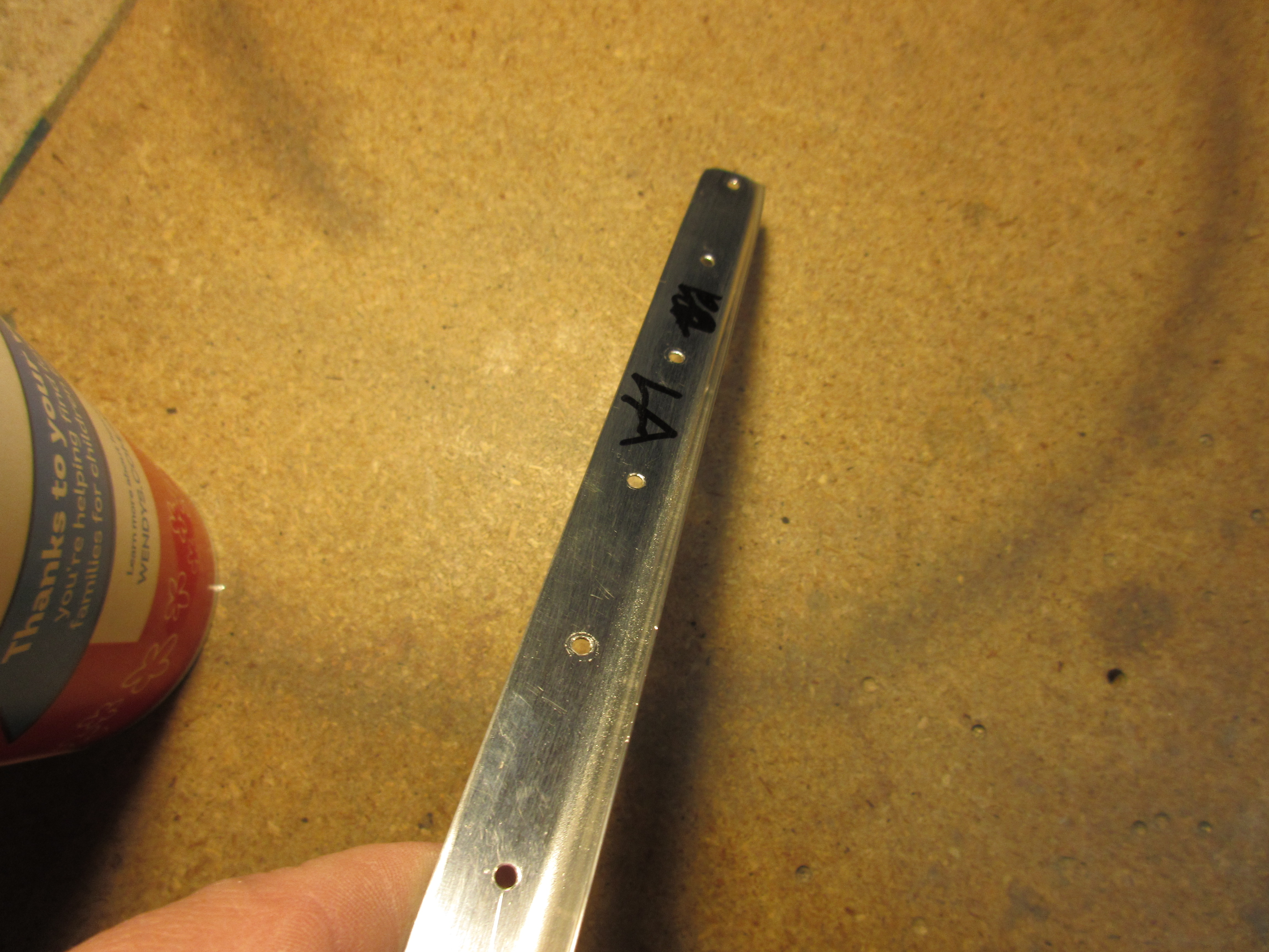
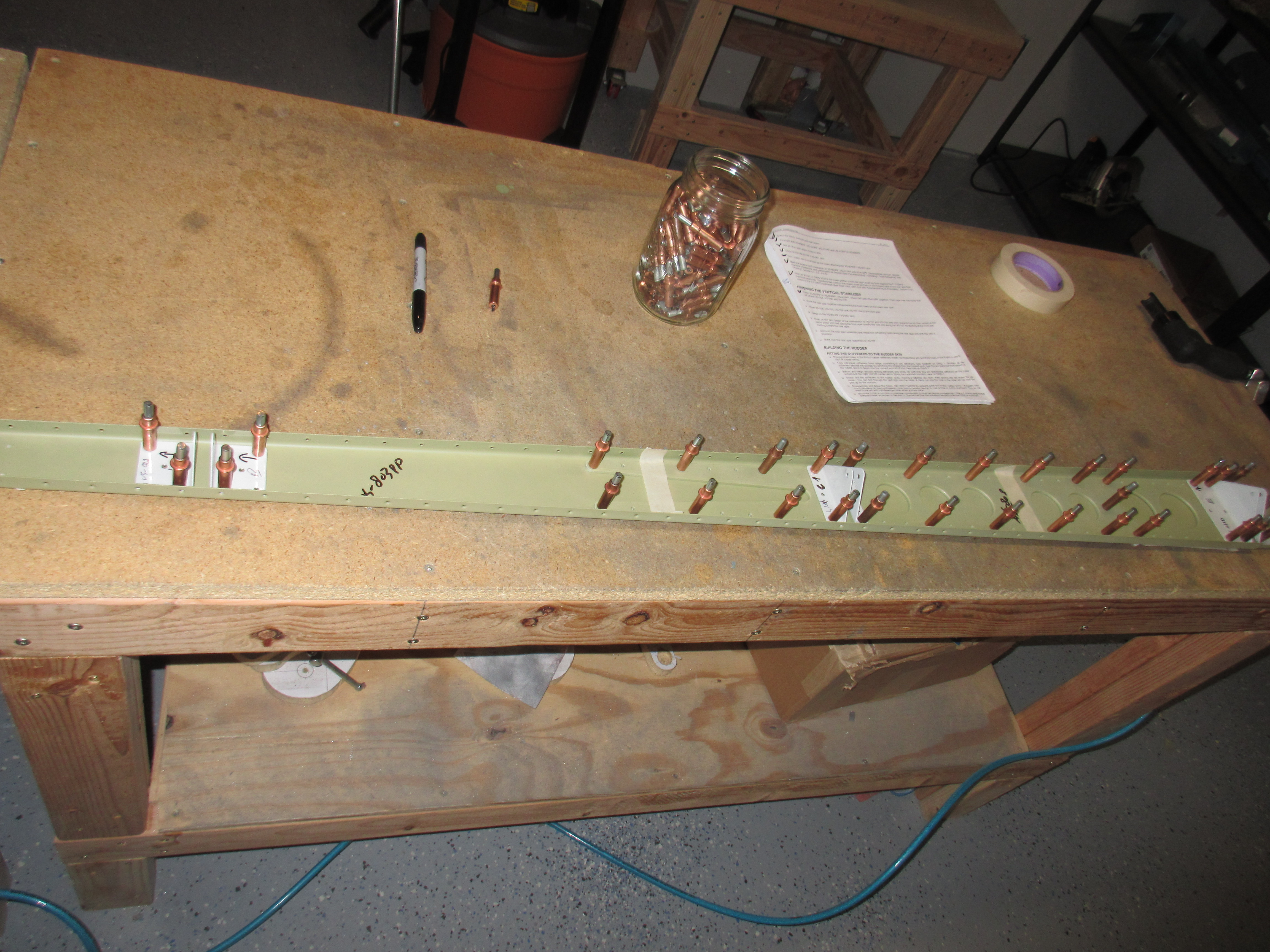
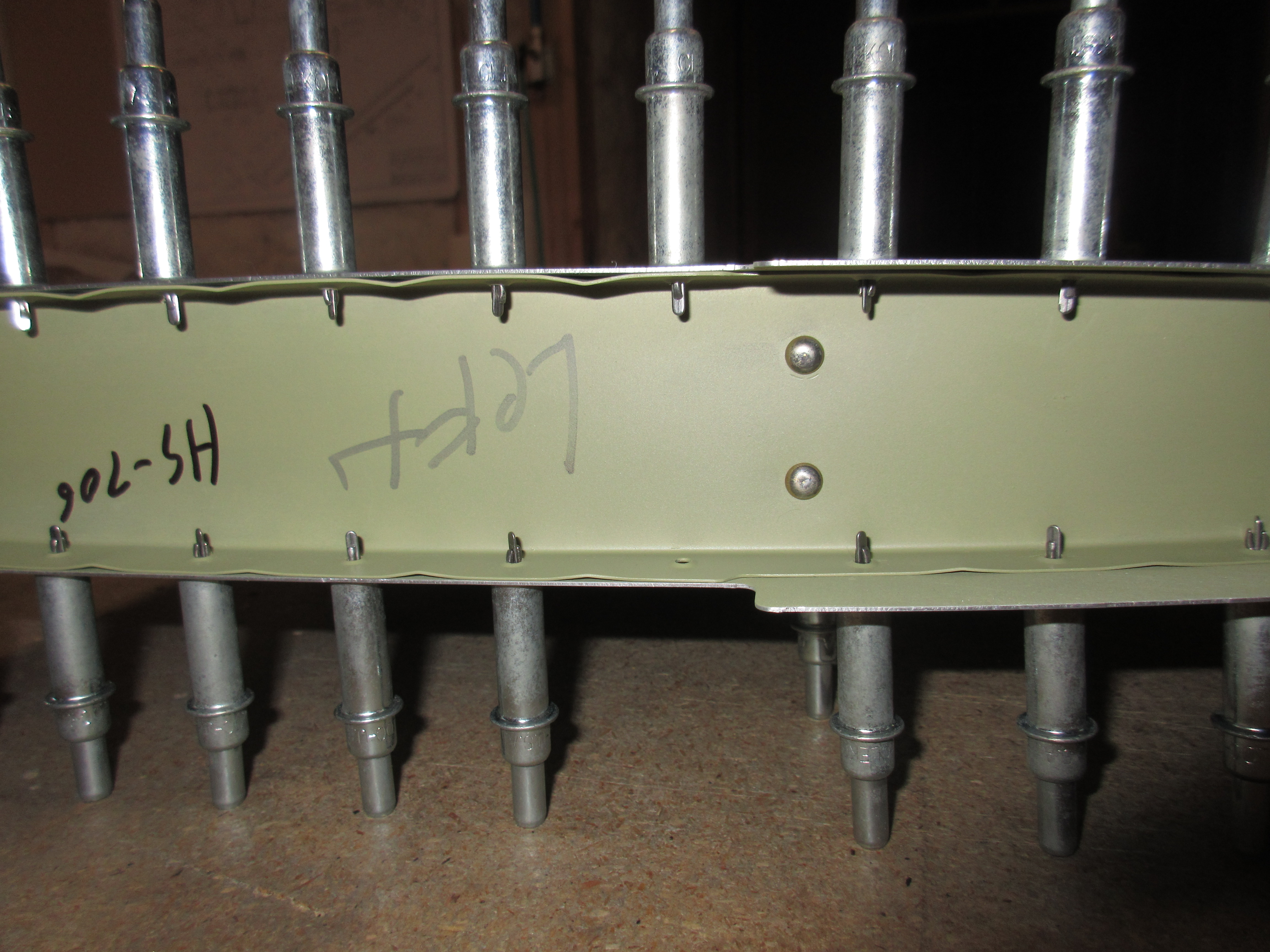
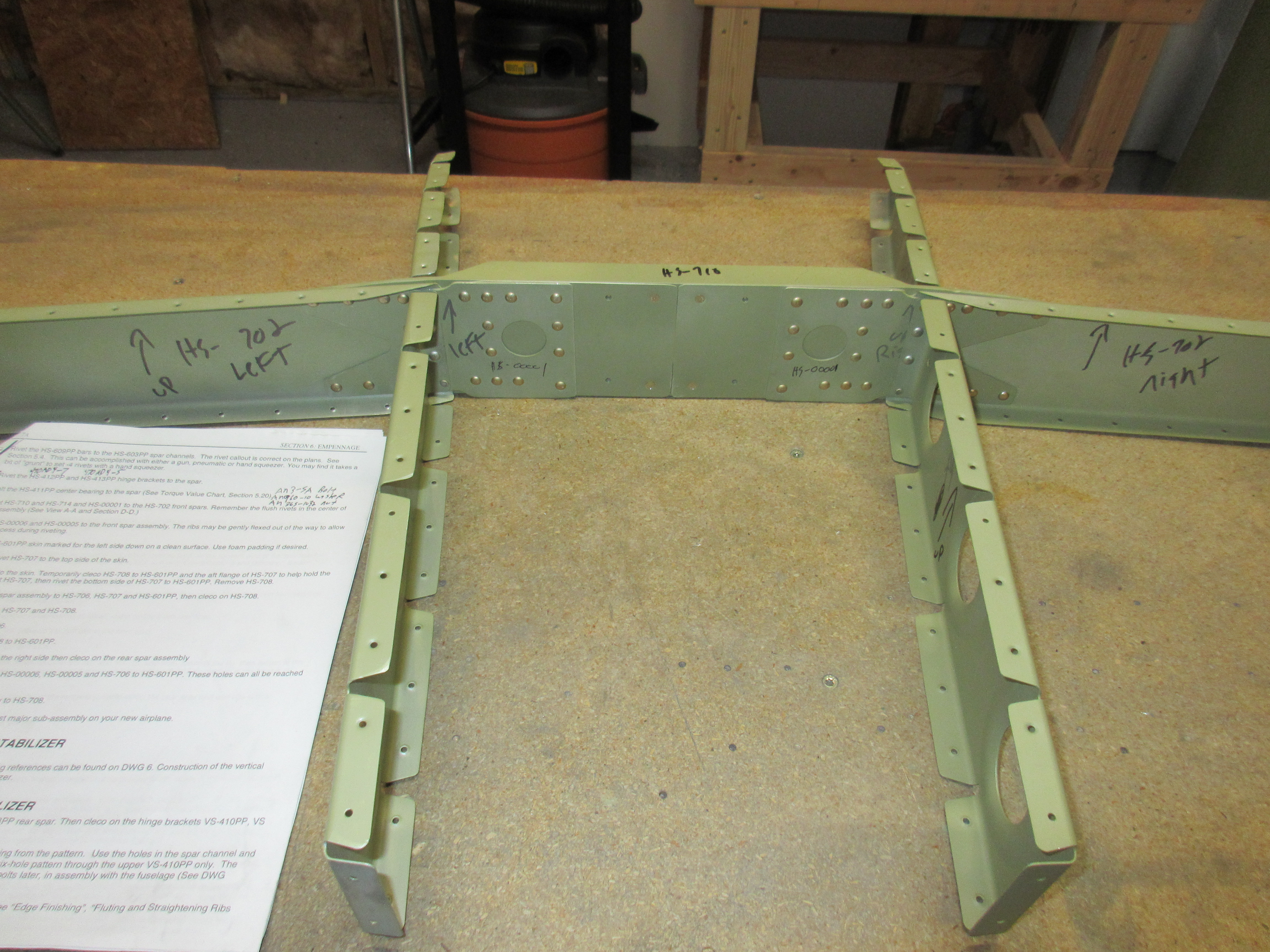
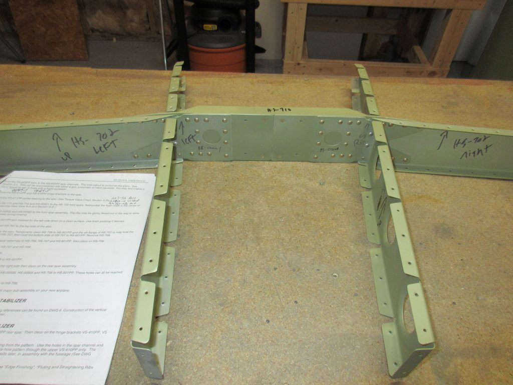
Tonight started off by riveting the HS-00005 and HS-00006 ribs to the HS-702 front spar.  I was able to use my squeezer to set these rivets, but only just barely! I had to do some finagling around the front spar support bars, especially the larger HS-714 to get the squeezer to line up on the rivet heads.  I did have to insert two rivets in the opposite direction in order to set them, but other than being cosmetic it won’t hurt anything.

img_0760

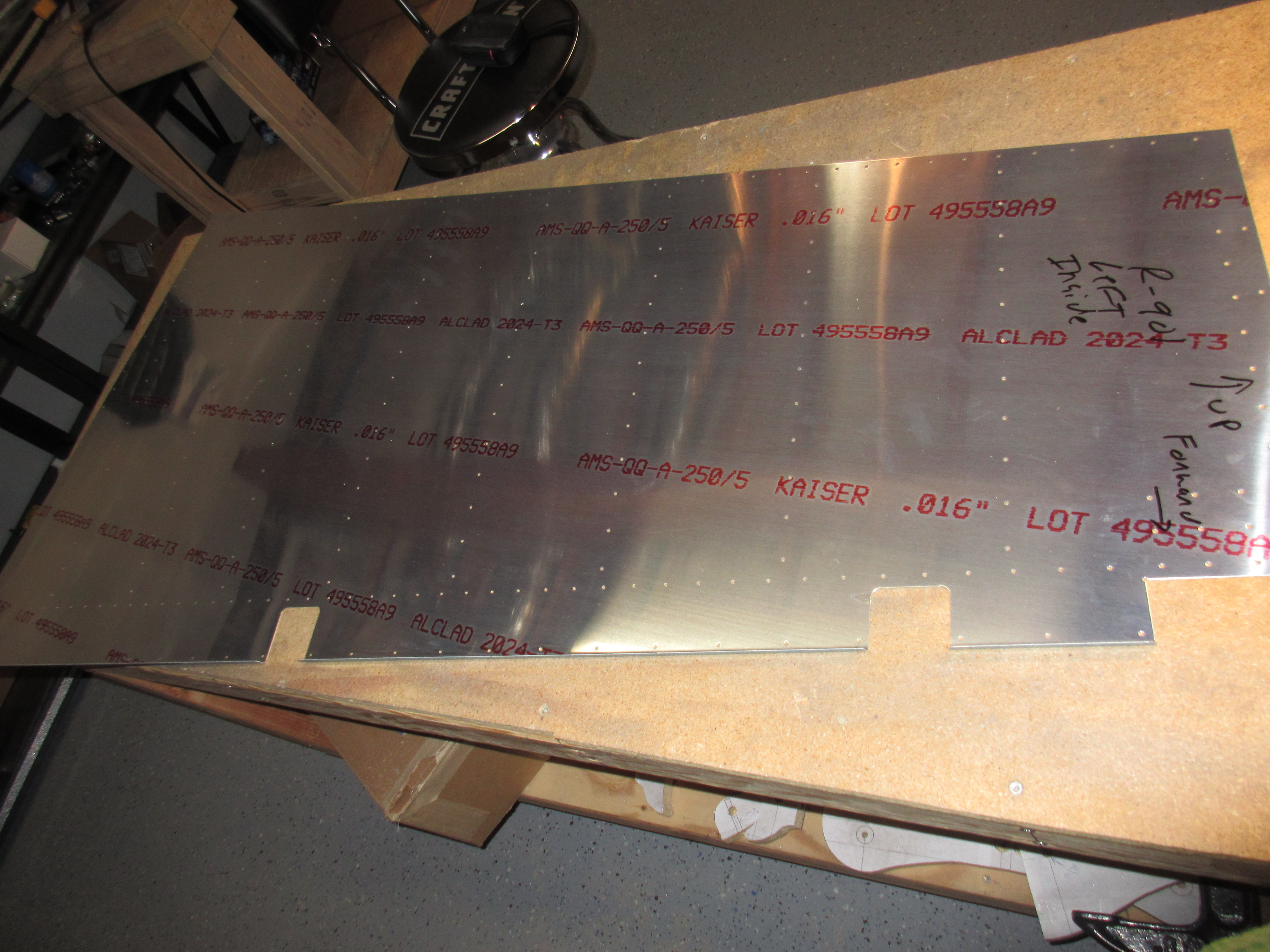
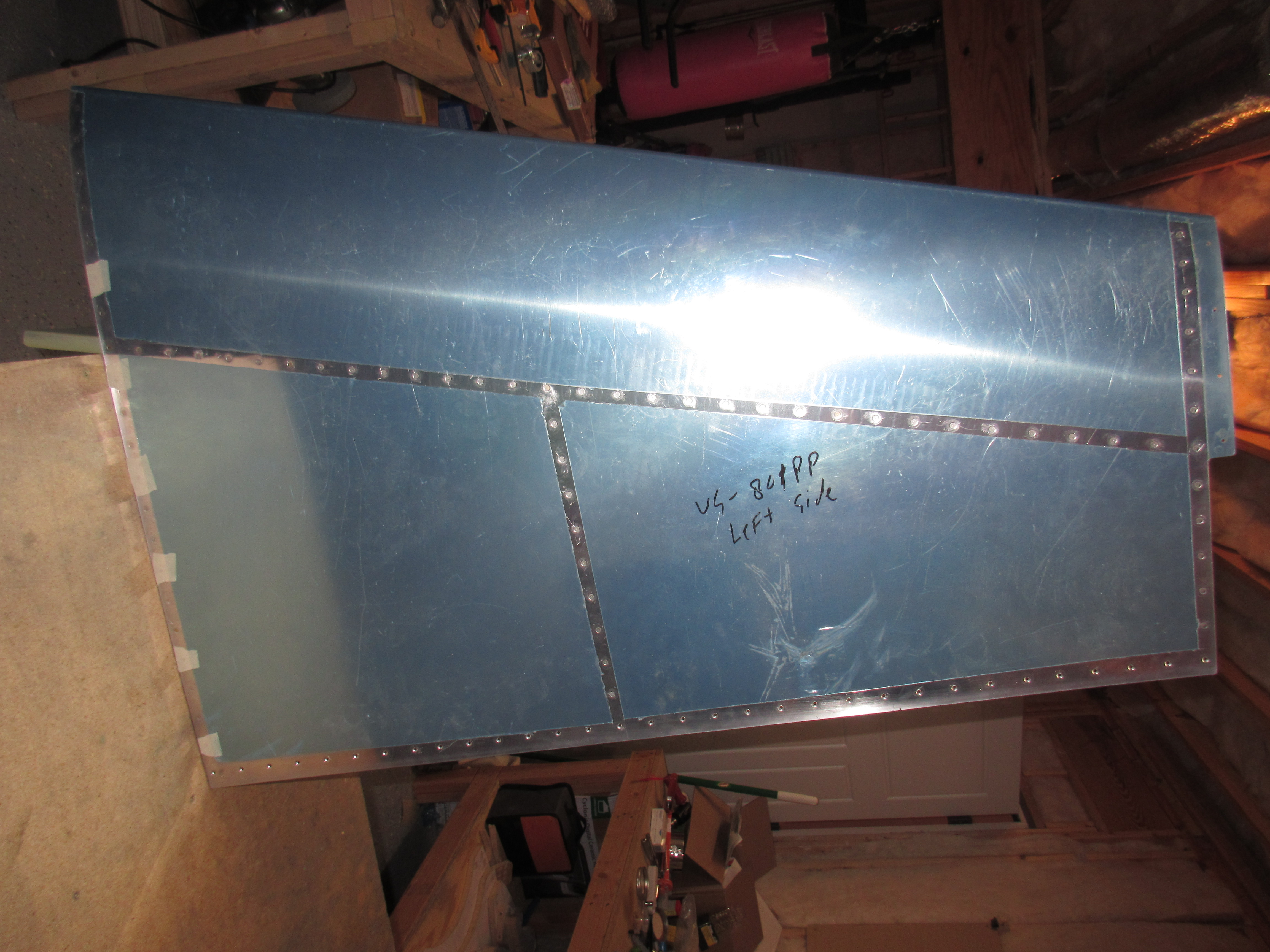
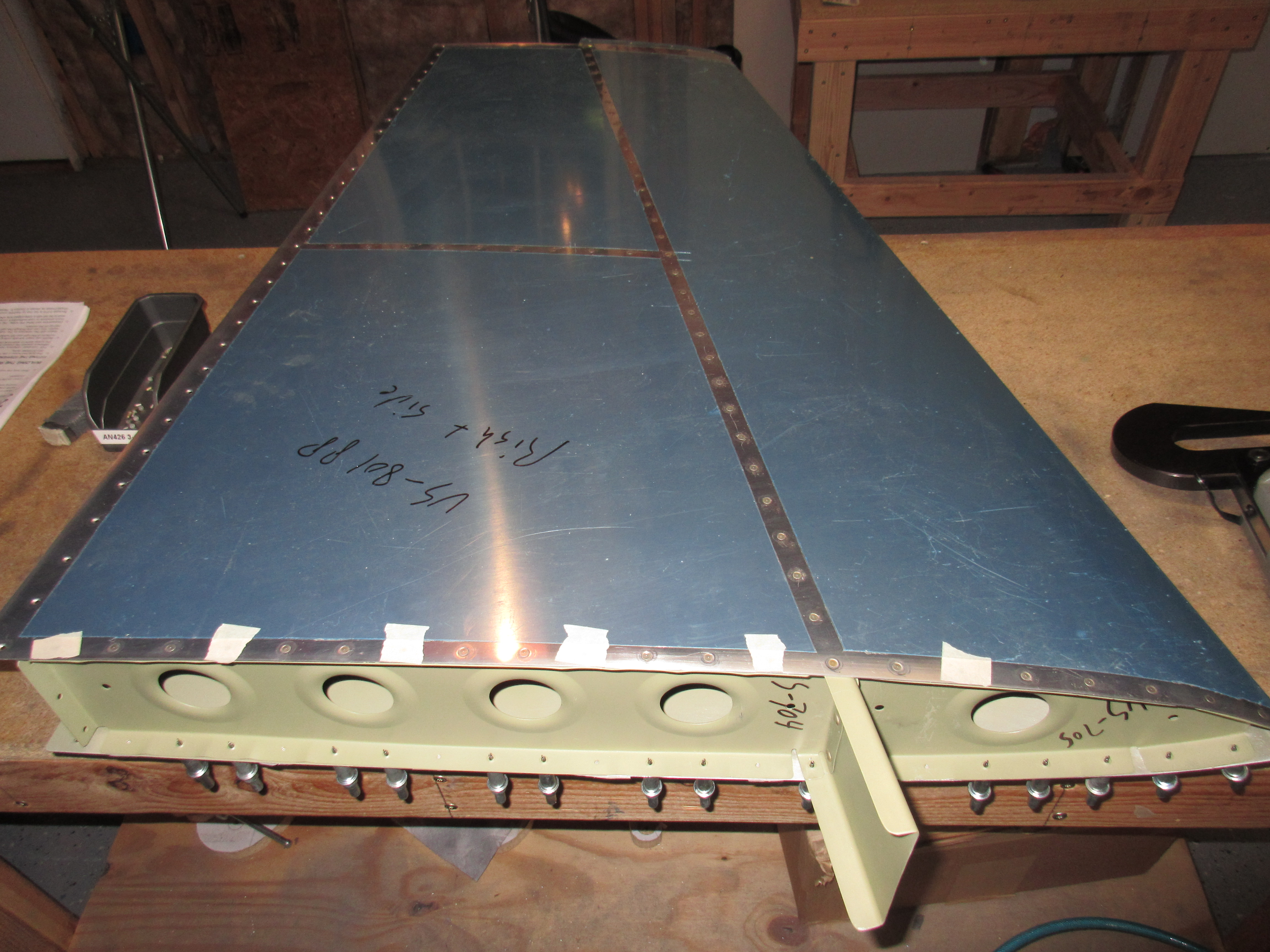
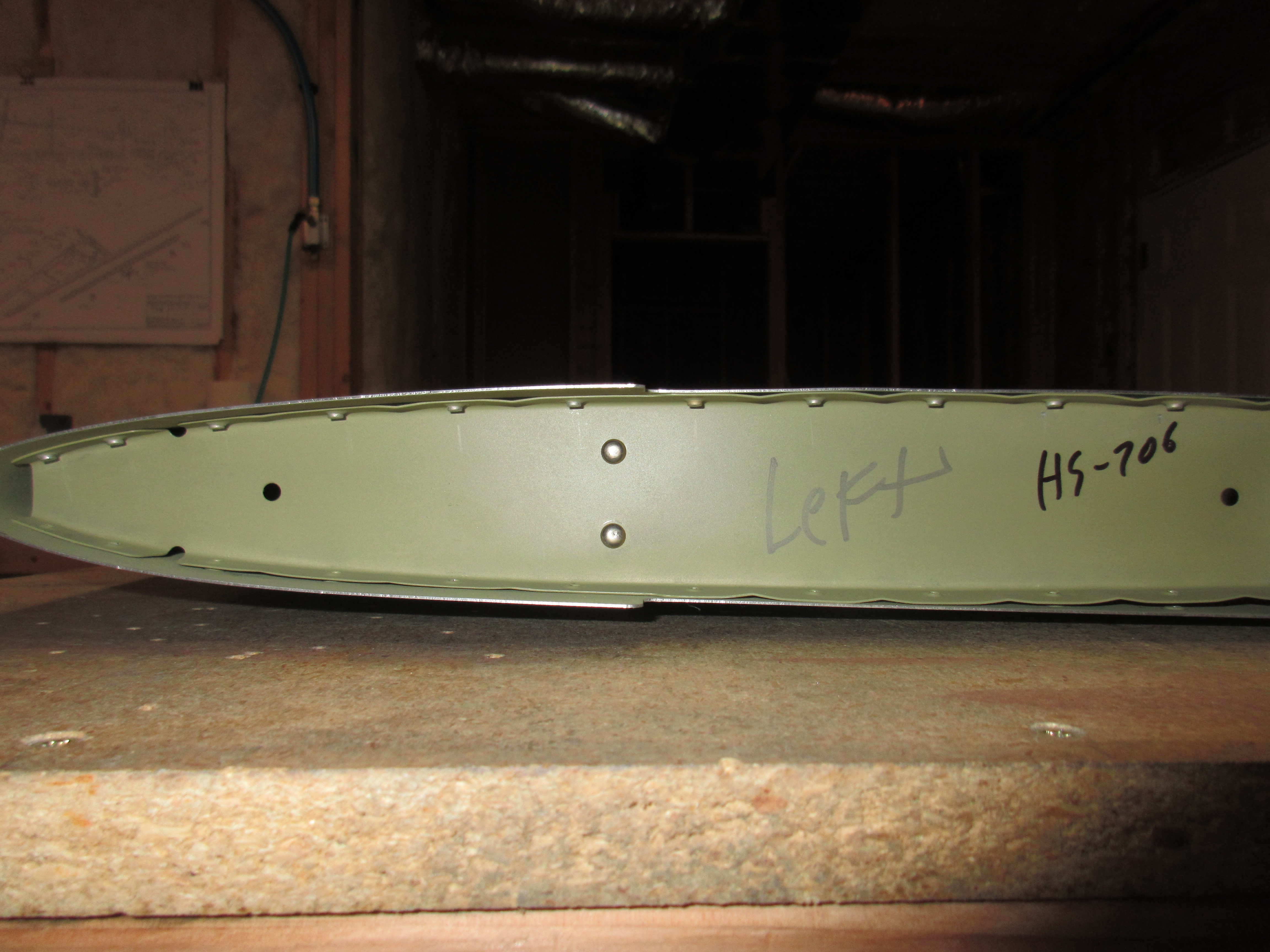
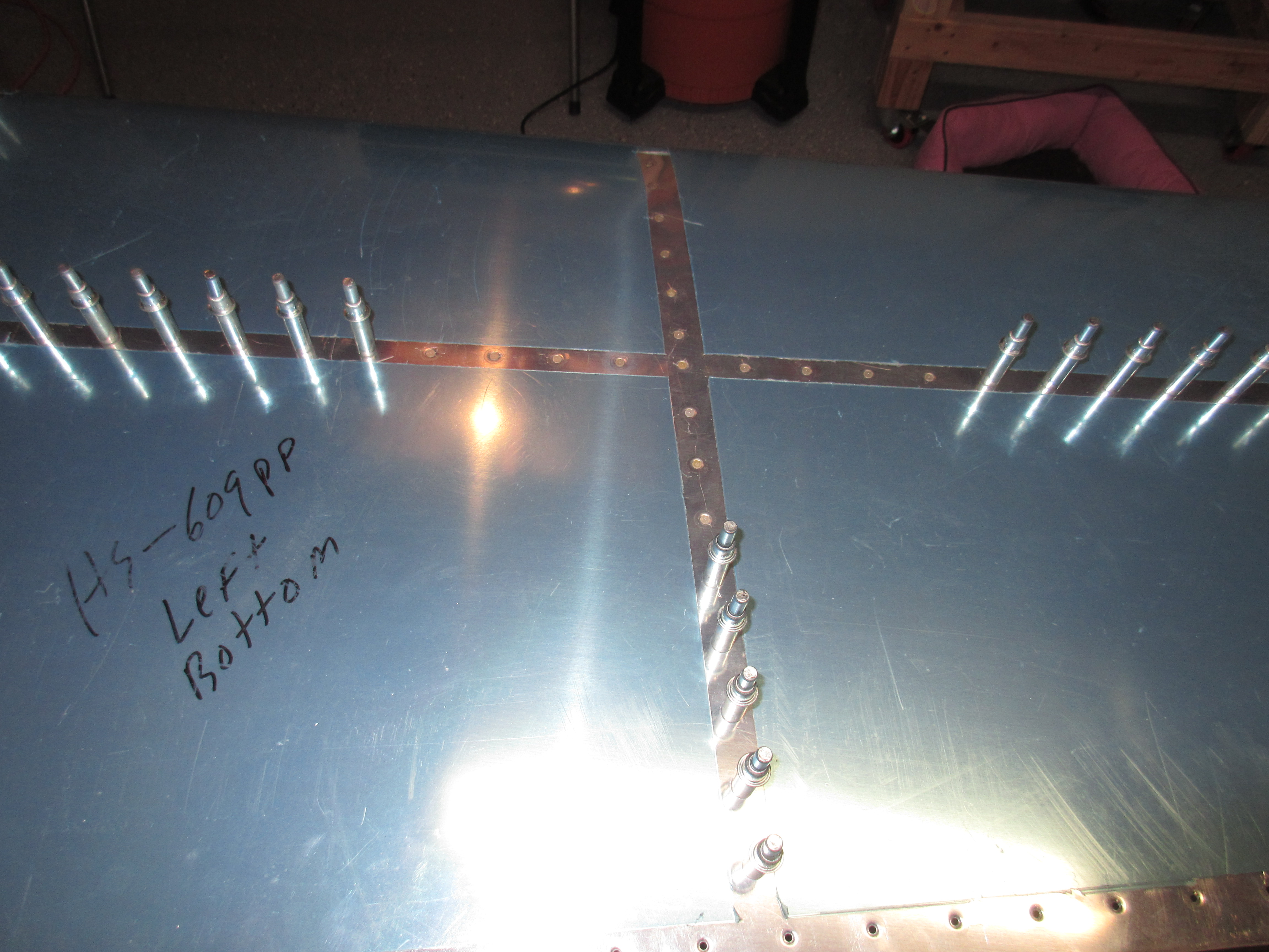
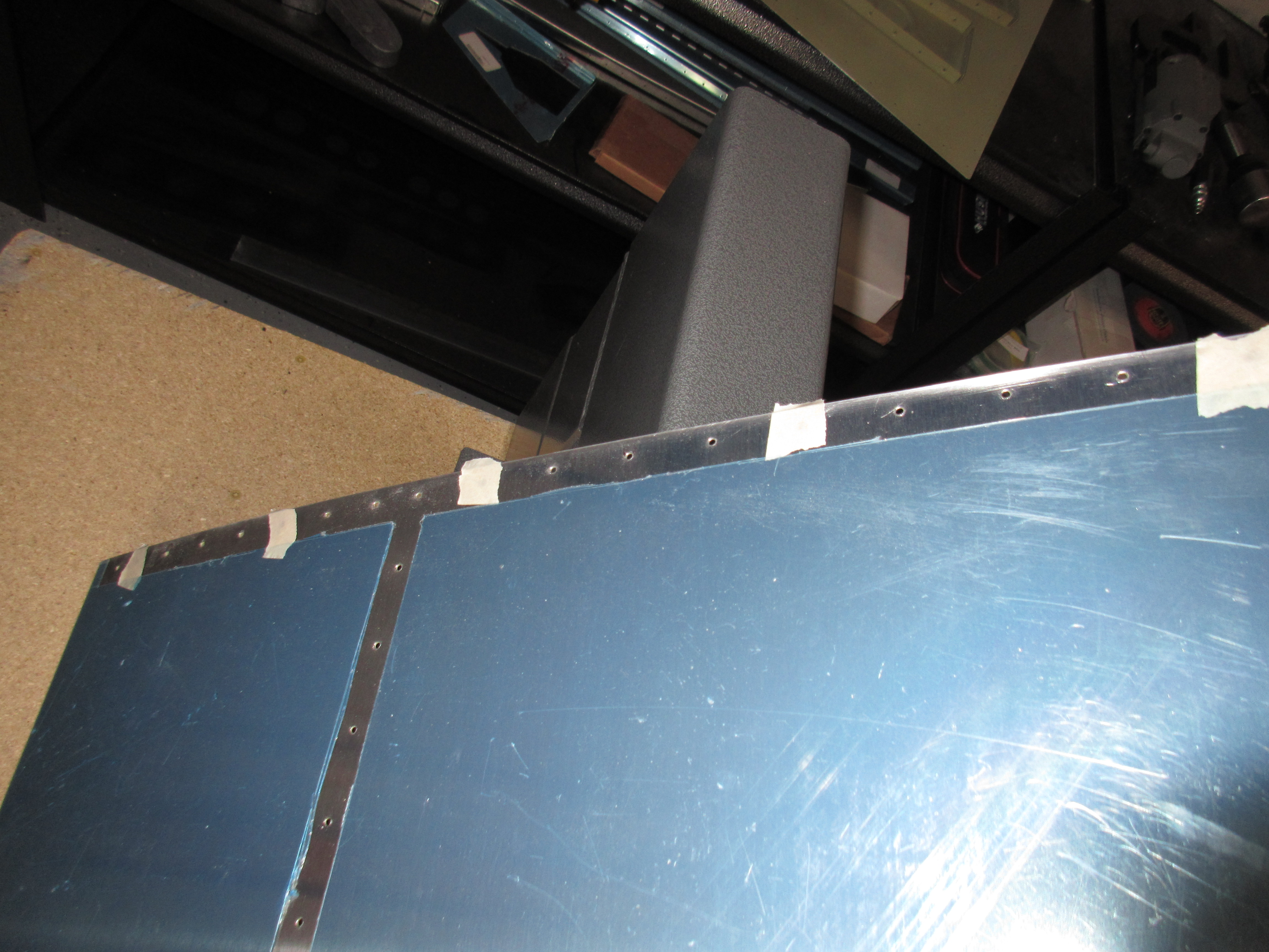
After completing the front spar, I moved on to the left HS-601PP skin. The plans have a unique way of final assembly, and after reading over the plans, and visualizing what would take place, I dived in.  This method is a bit different than the George Orndorf method I watched in his videos, but I am not using a RV-6 jig.

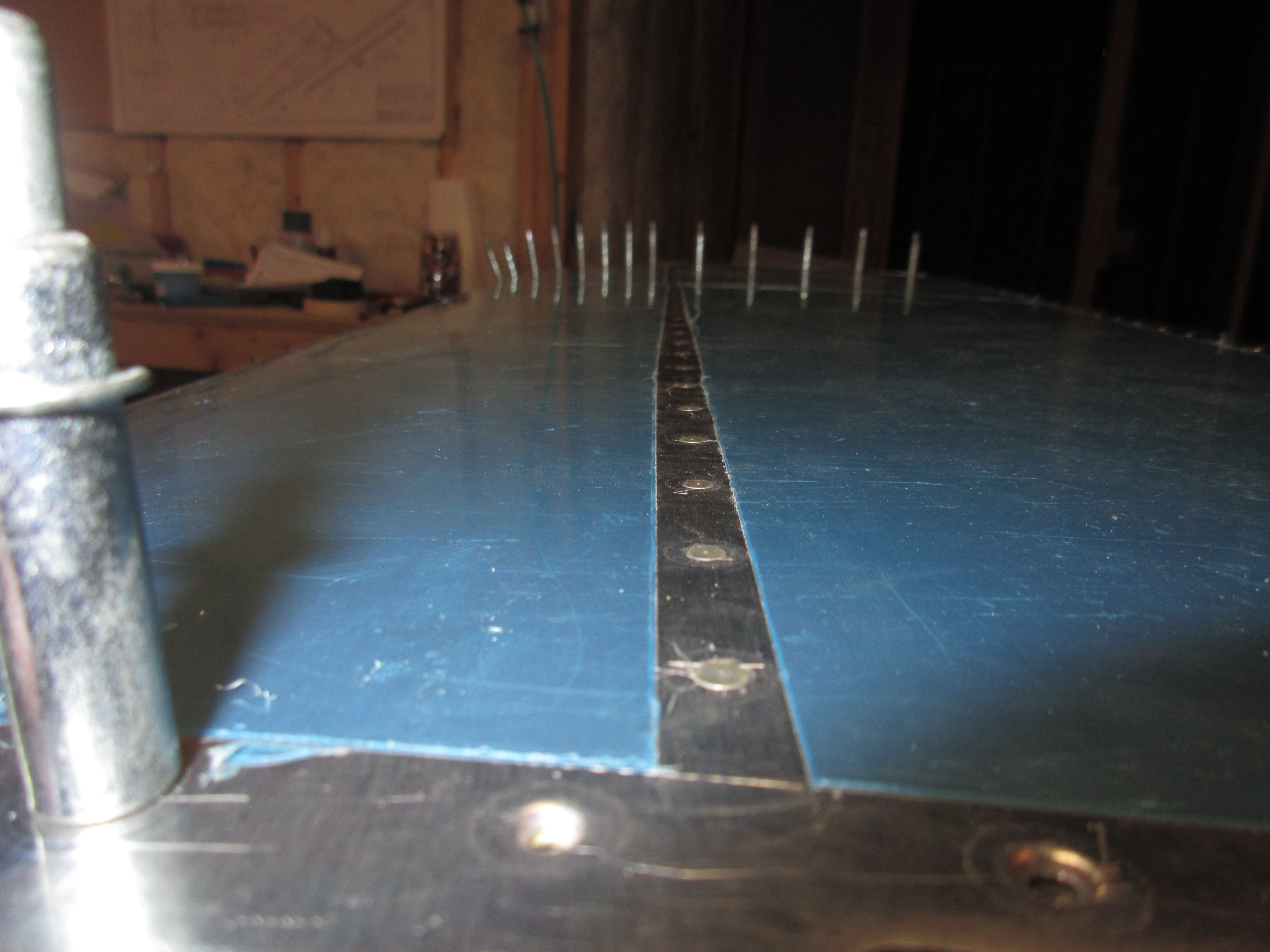
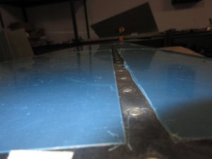
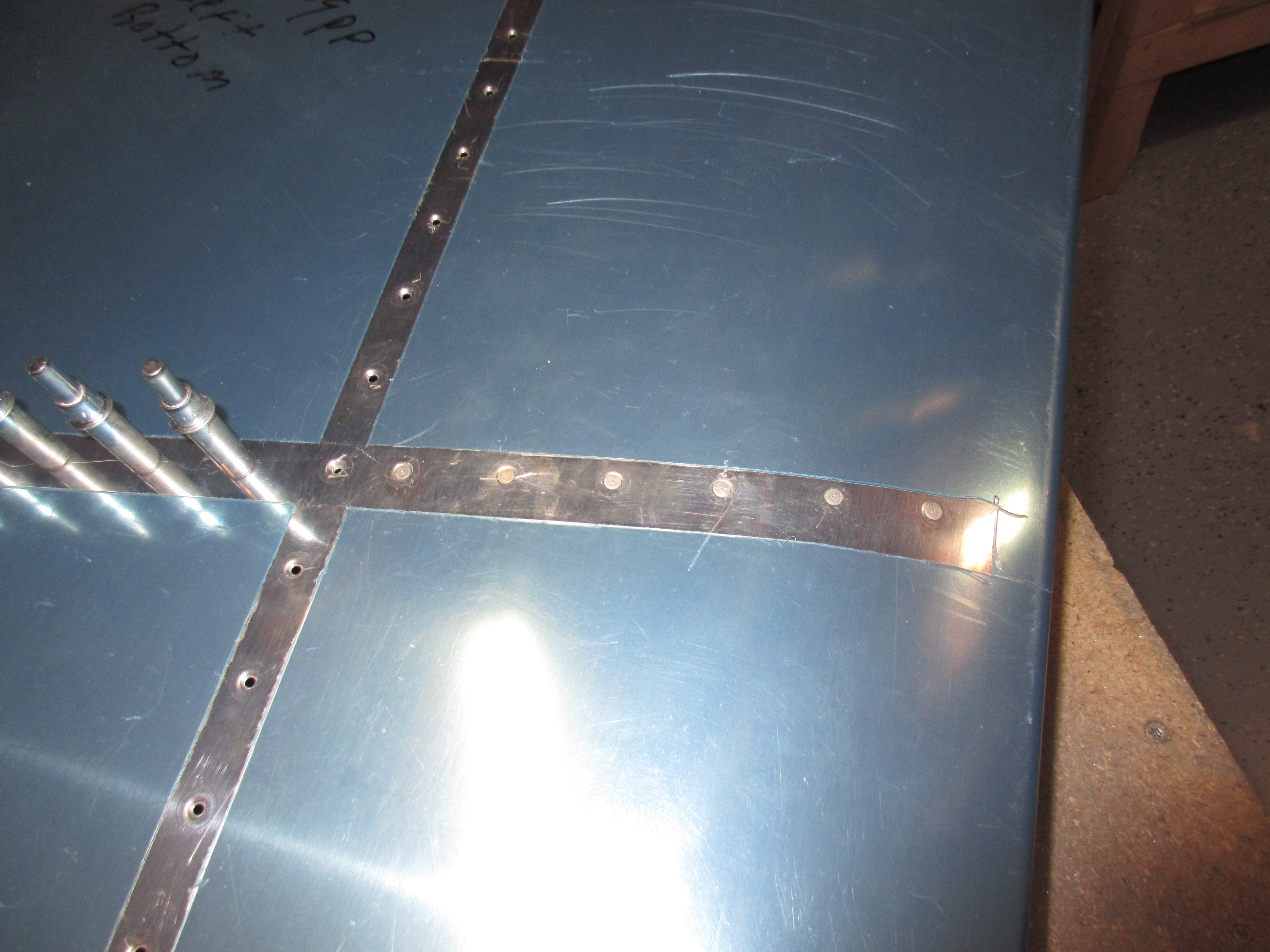
It starts off my clecoing HS-707 nose rib to the skin and then riveting it. After making sure everything looked good and flush, I riveted the rib to the skin.  This was the first official piece of work that I riveted that would be seen from the outside, so I went slow and took my time.  I was happy with the results!

img_0770

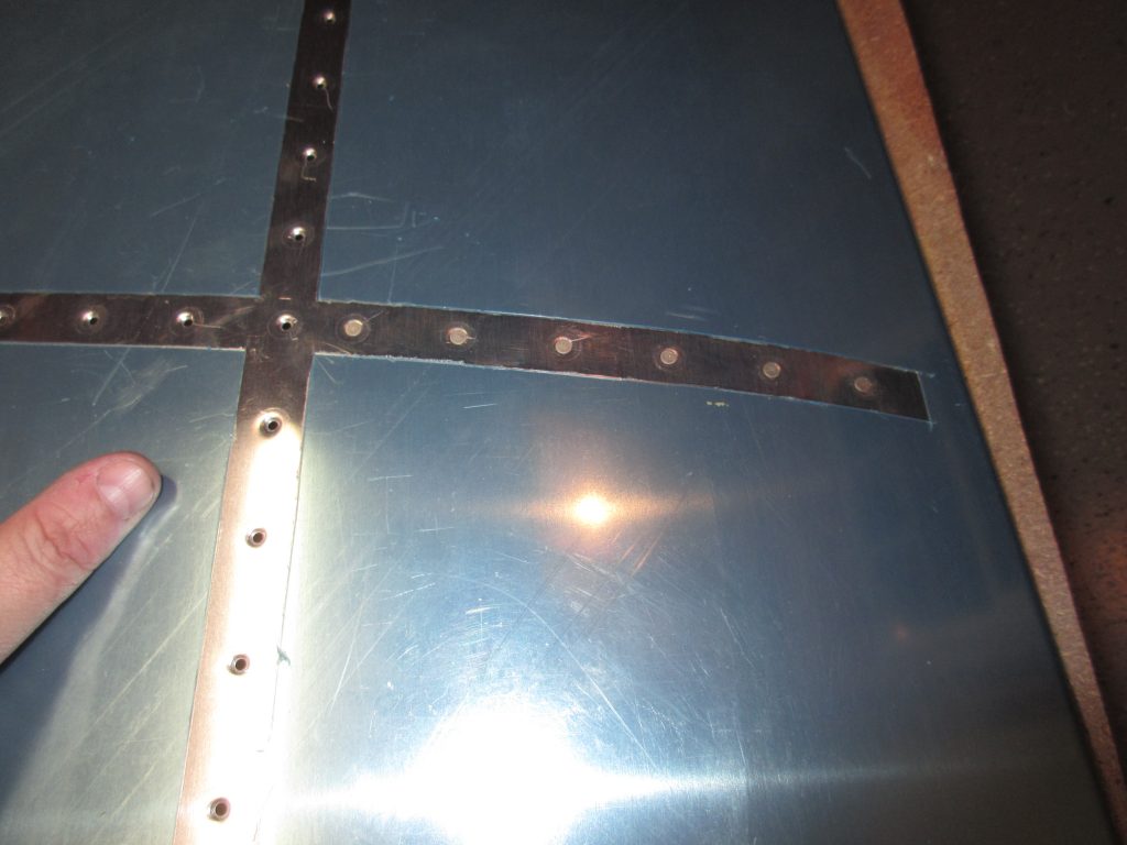
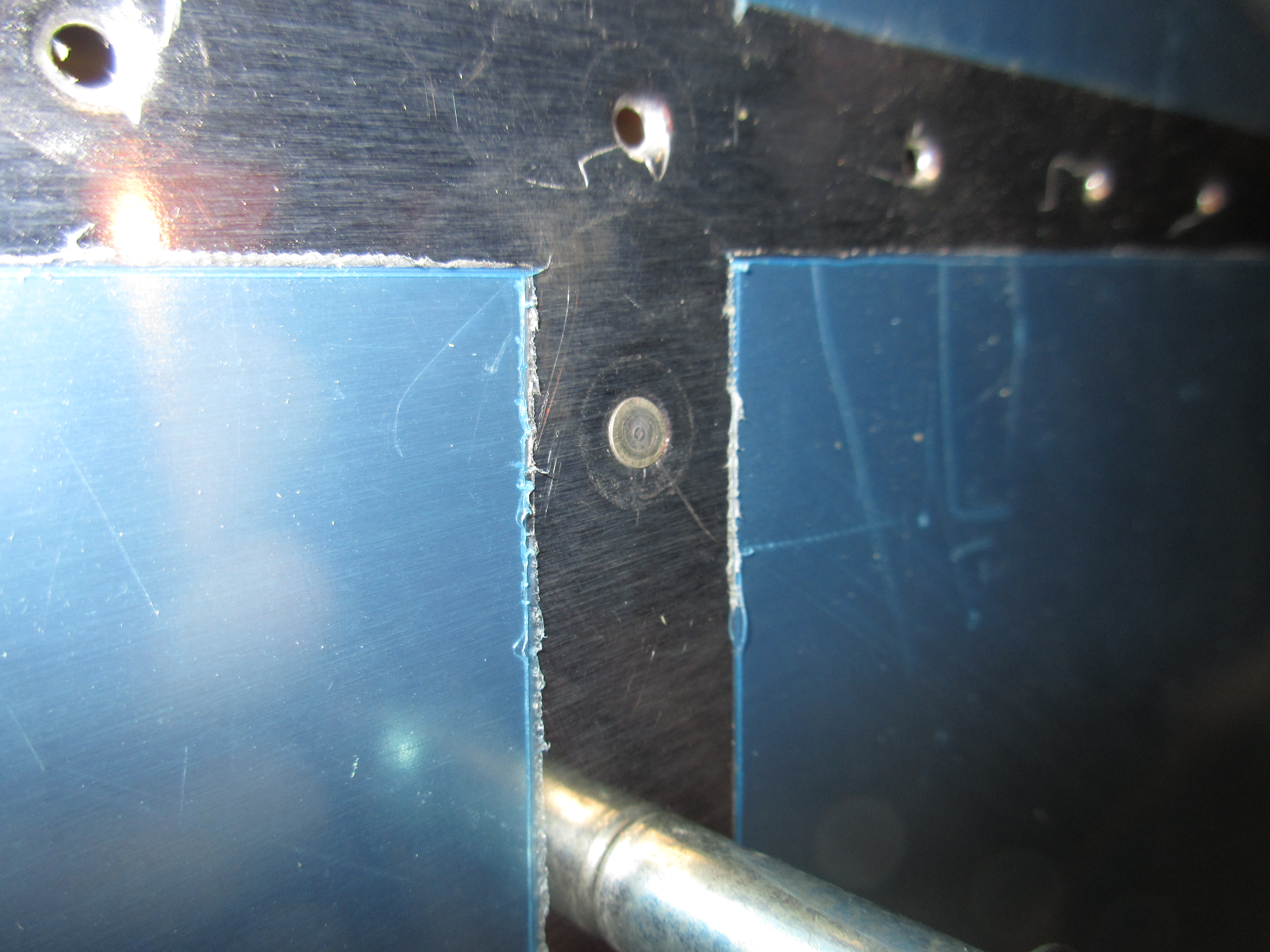
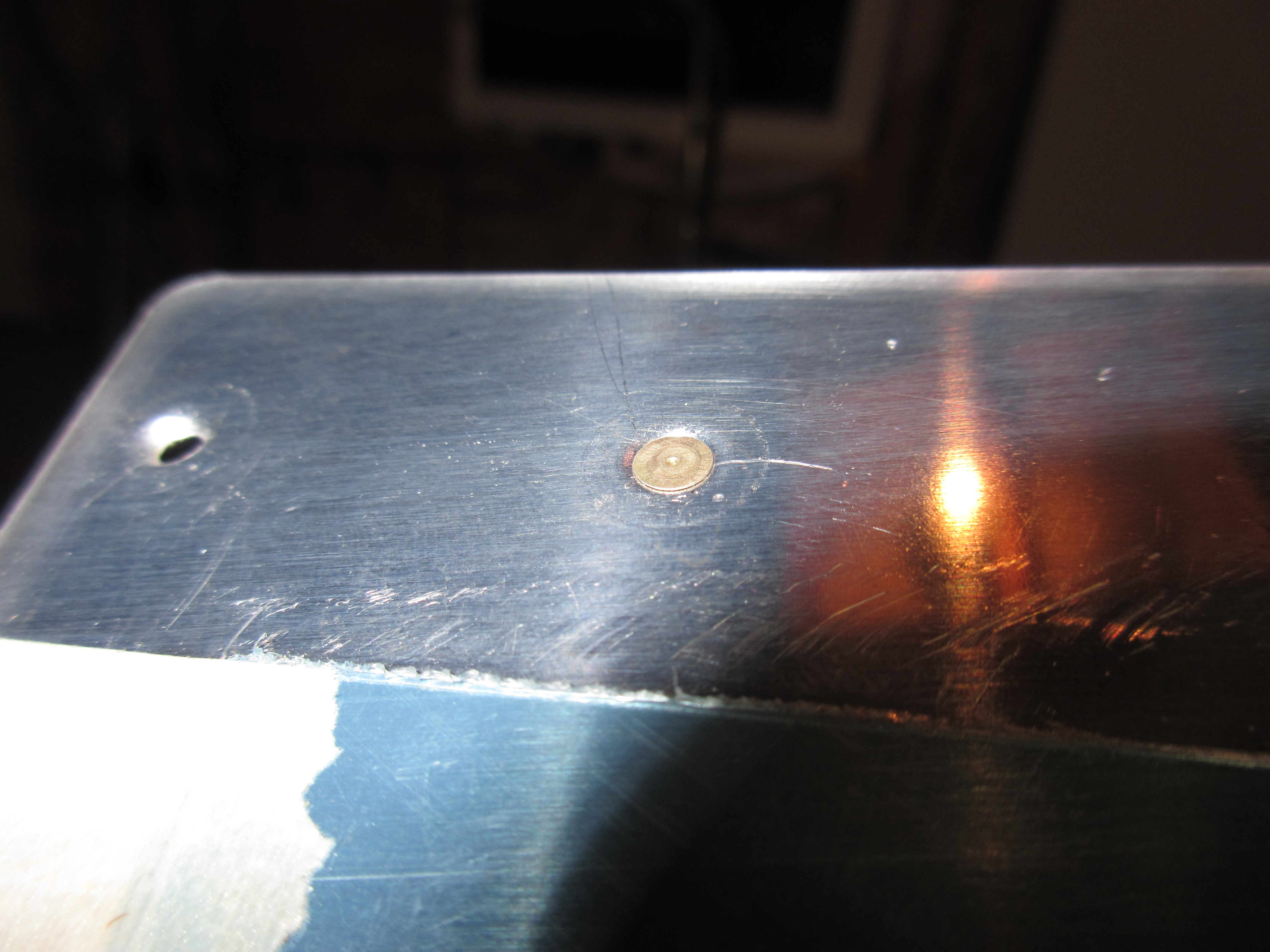
And this was the first ever flush rivet to be set!

img_0766

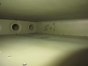
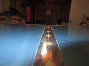
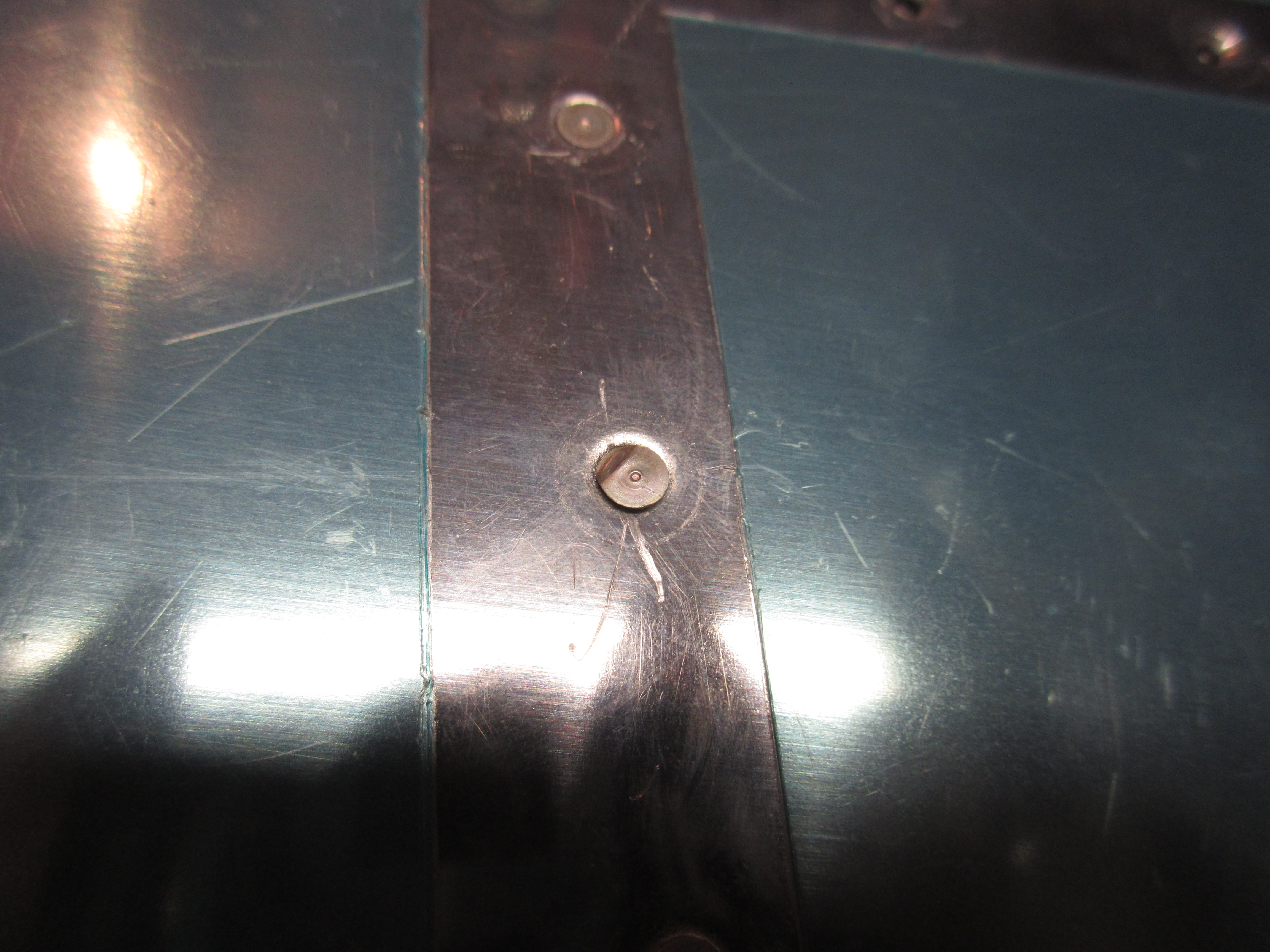
After riveting on the HS-707 nose rib to the top skin, the plans have me cleco the end rib, HS-706, to the skin, as well as HS-708 to help hold everything tight.  This makes riveting HS-707 to the bottom of the skin much easier.  HS-707 nose rib was a tricky part to rivet! I messed up two rivets so I had to drill them out and replace them after I got all the other rivets done.  I have practiced this on scrap material a bunch of times, so it was no biggie.

img_0775

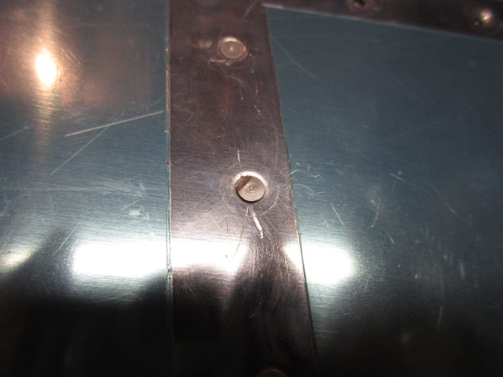
And voila! You can’t even tell it was fixed:

img_0779

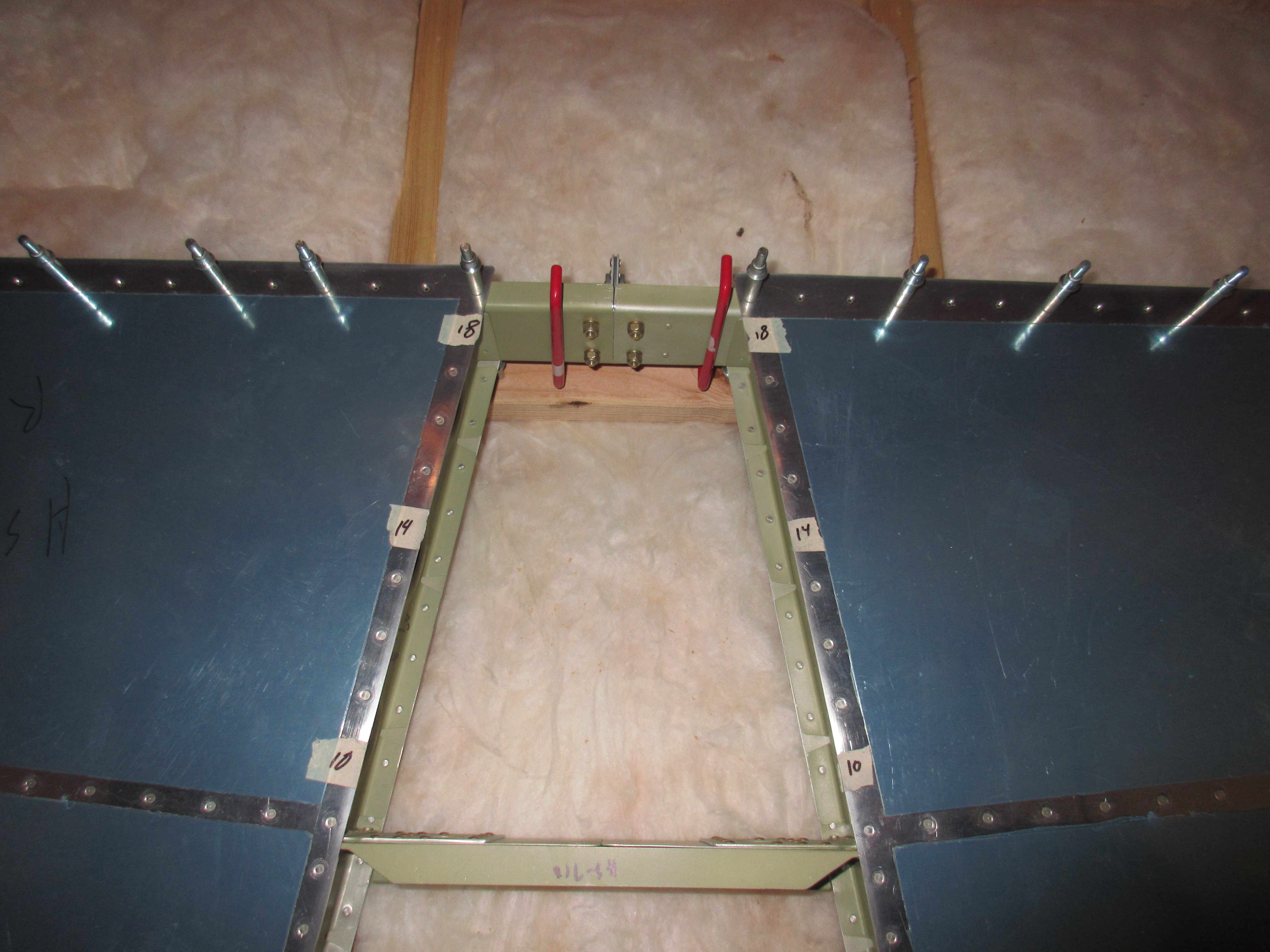
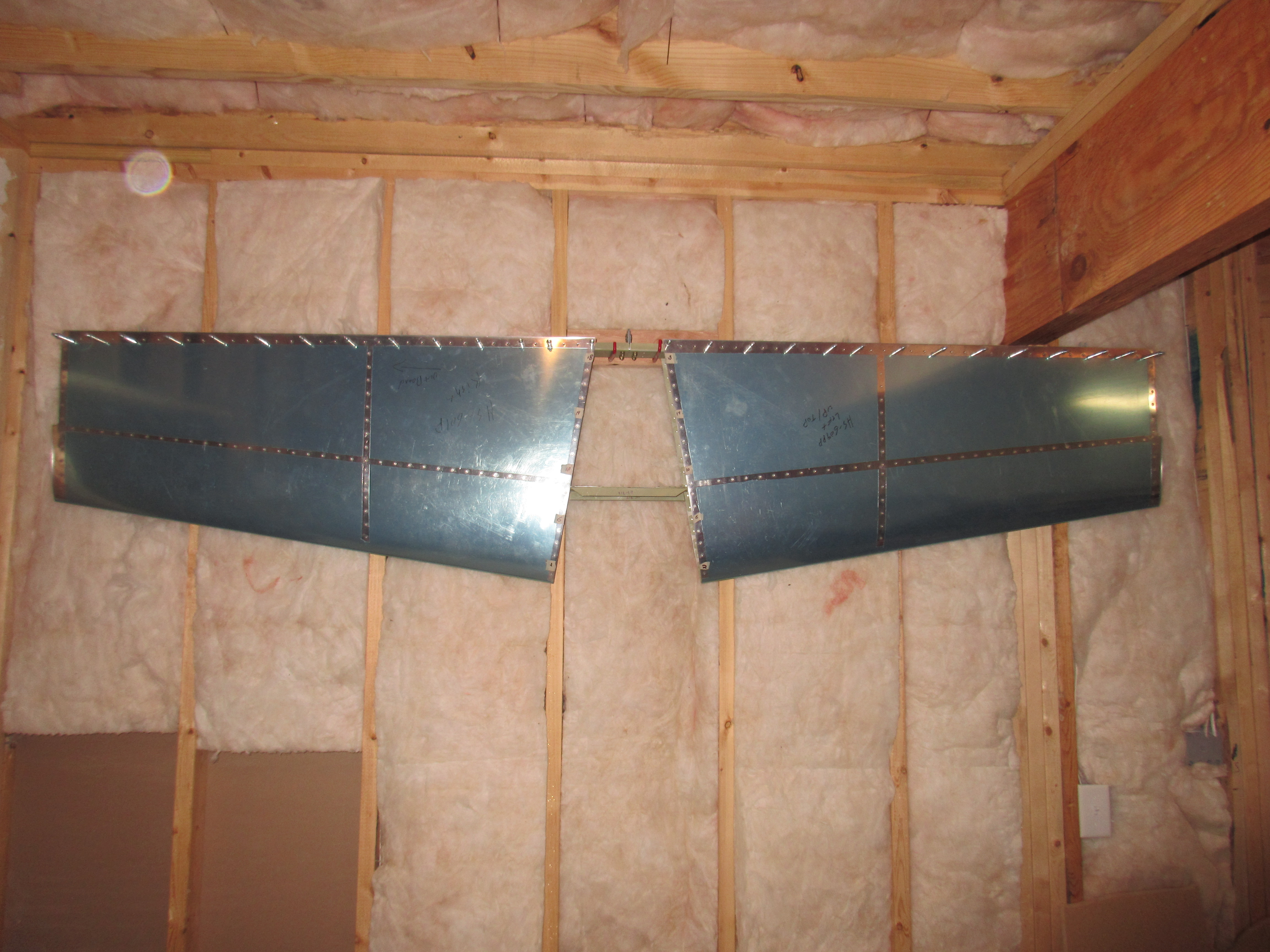
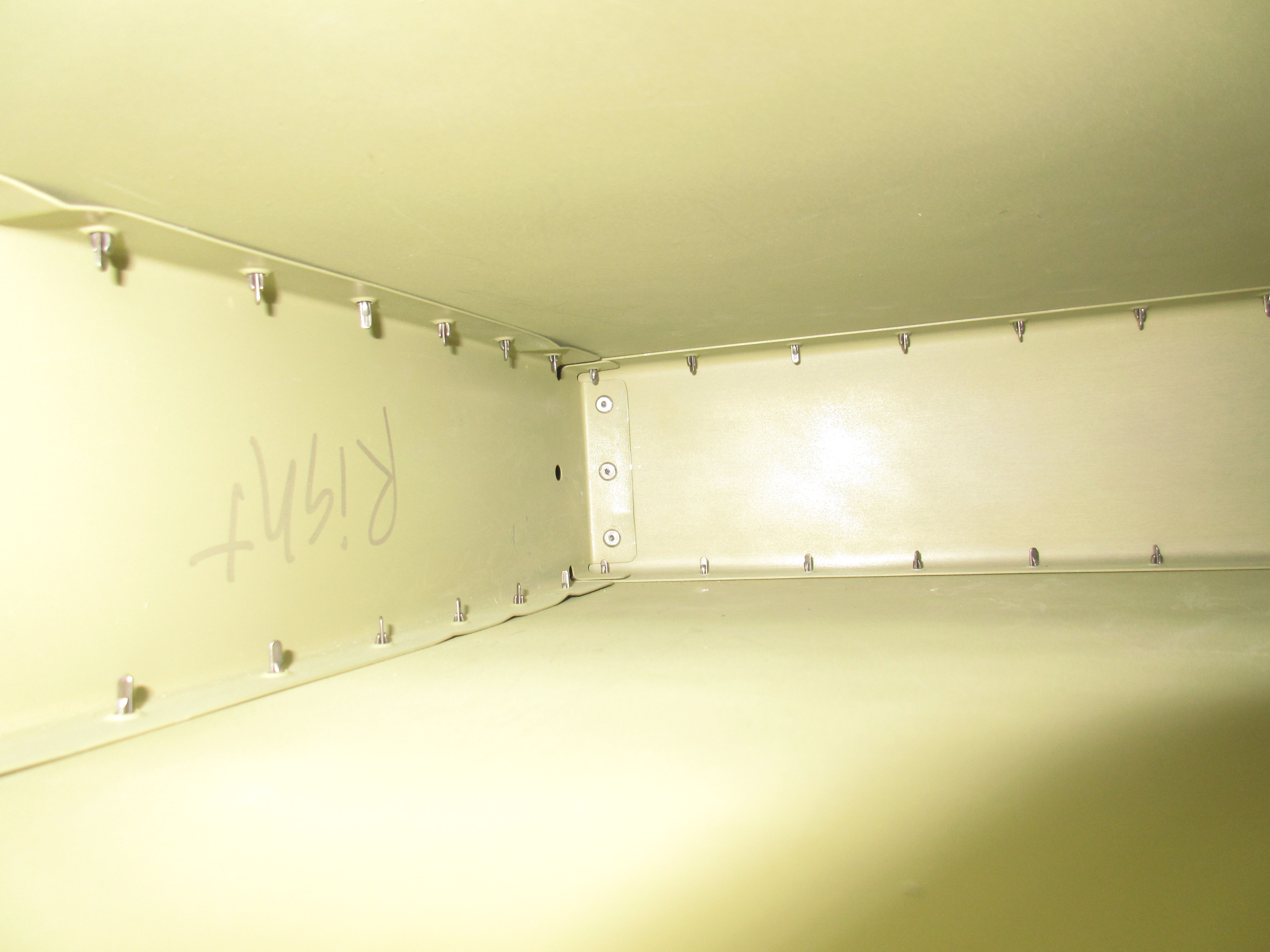
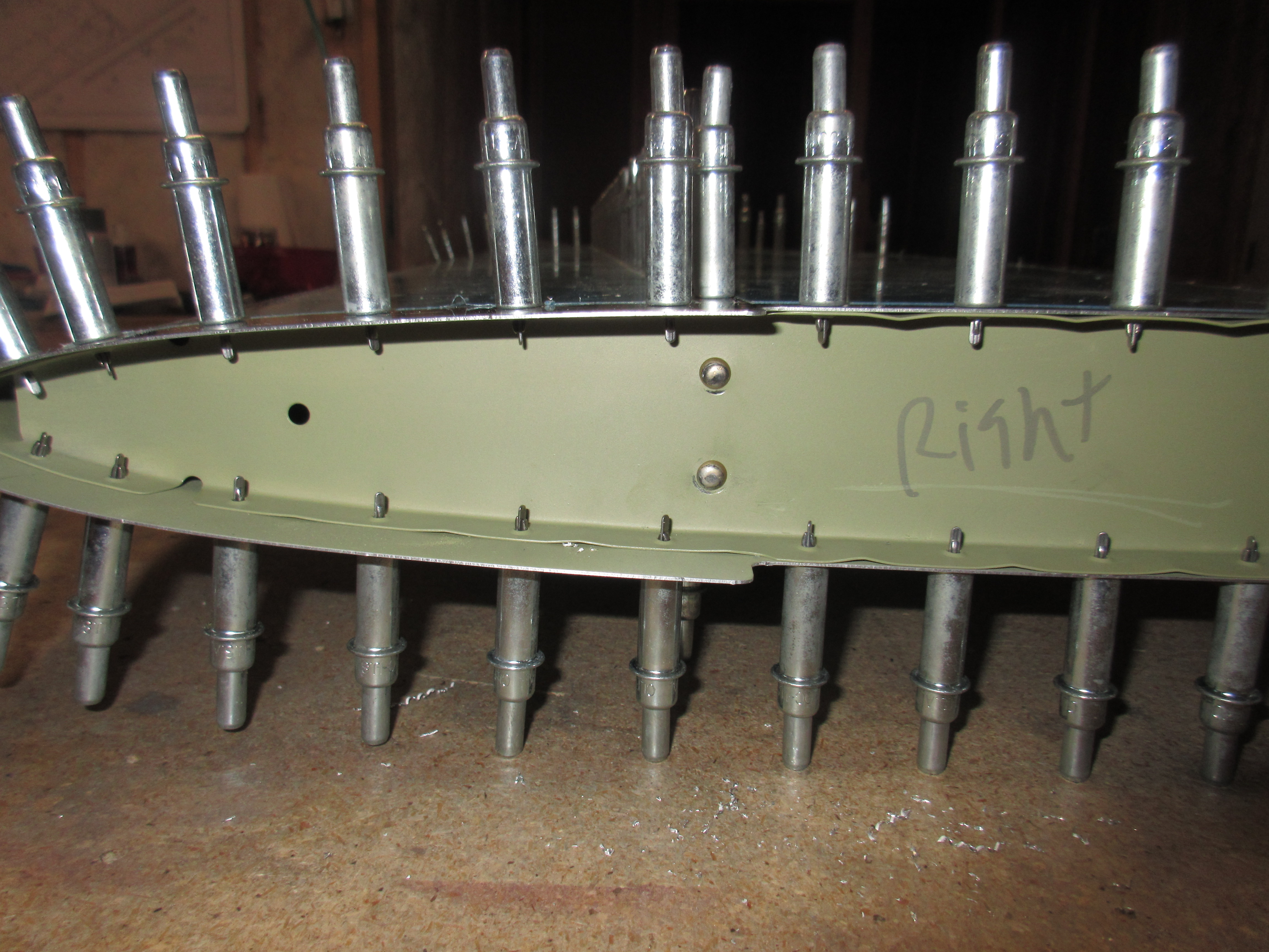
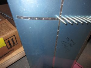
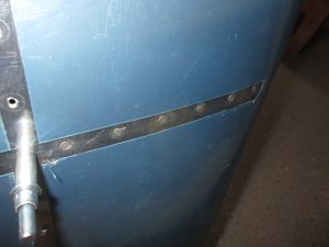
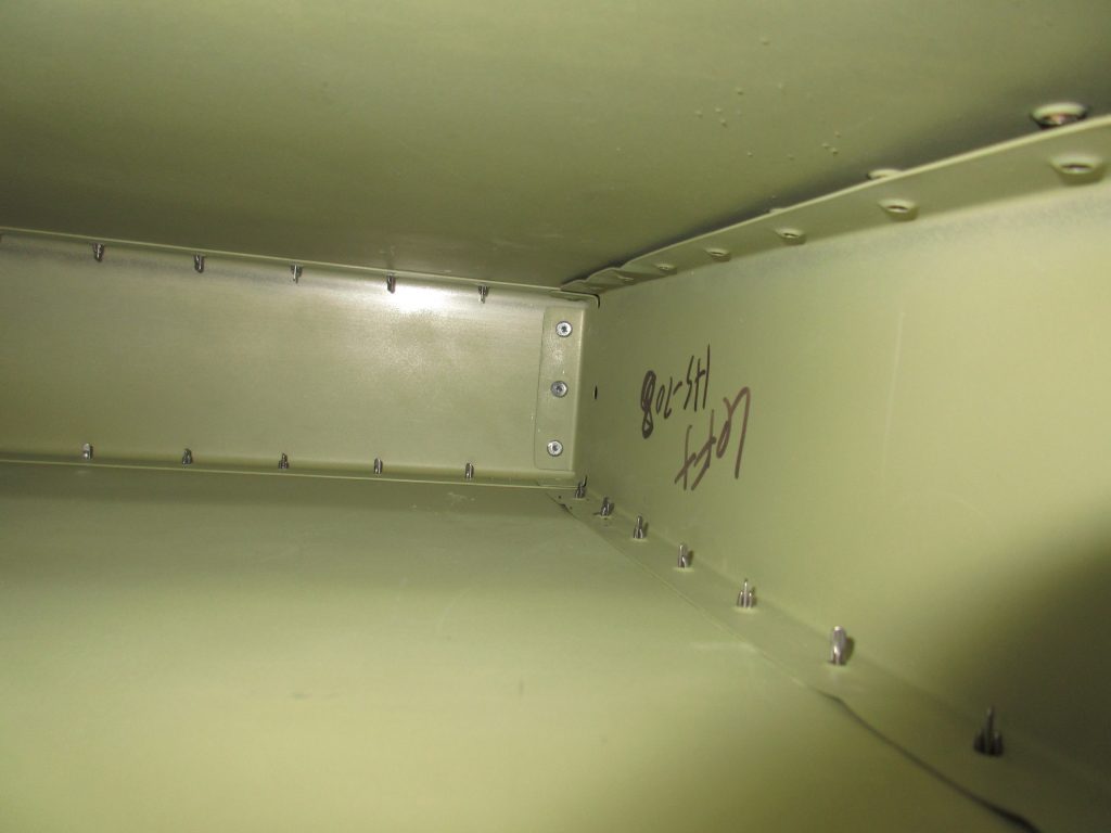
Once I had both sides of HS-707 nose rib riveted and done, the next step was to insert the front spar assembly so I can be riveted in place.  So I got it all situated, and made sure everything was lined up and clecoed every hole to hold it in position.  Once the front spar was fastened, the plans have you use a blind rivet (pop rivet) to hold HS-707 nose rib to HS-702 front spar and HS-708 middle rib. These rivets were a little tricky because the space is pretty tight and I have big ole gorilla hands.  Not to mention the head of my pop rivet squeezer barely fit between the rib and the rivet mandrel.  But, after some patience and a little wiggling, I was able to fully seat the three blind rivets that holds those two ribs to the front spart assembly.

img_0783

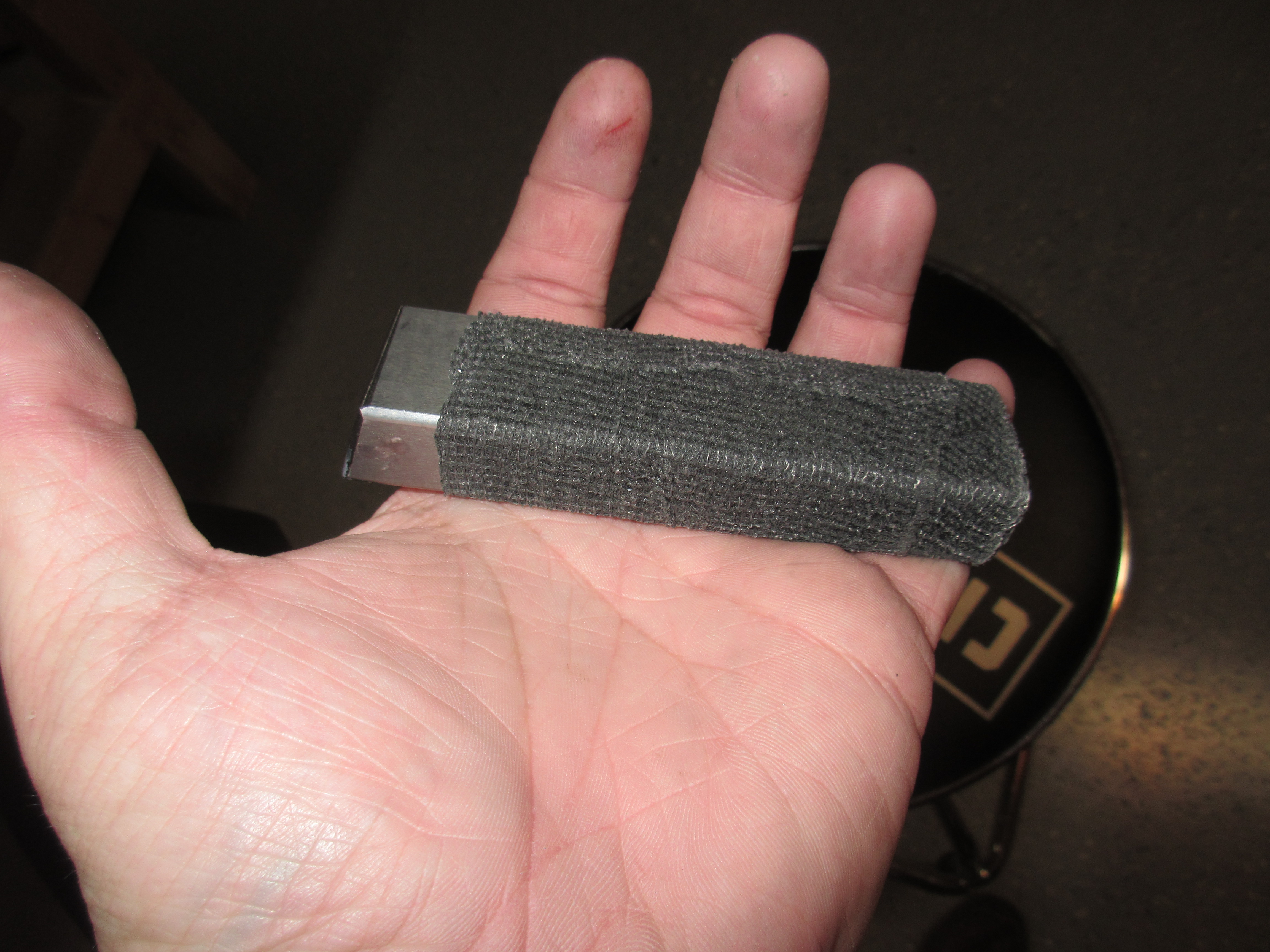
As a side note, I learned from the Vans Airforce Forums that a good trick to protect your skins during riveting is to wrap your bucking bar in athletic tape, except for the tiny bit you are using against the rivet tail.  This is a really good suggestion, because it helps you hold on to the heavy bucking bar, AND protects the primed surfaces from getting scratched up from the sharp edges.  Since the athletic tape doesnt stick to anything but itself, it leaves no residue on the bucking bar!

img_0784

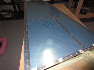
Thats all for tonight.  A little over 3 hours of work and I have my left horizontal stabilizer partially riveted and ready to finish up.  I will leave the other work for another session when I am a bit more refreshed and ready. Here is an album of all the photos, some showing better detail of the work.

And here is a link to the Google Photos album: https://goo.gl/photos/KbJZJgAqgg6pmFCt8

Hours Worked: 3.25

Dimpling the Left Horizontal Stabilizer

After riveting the front spar, I was still wanting something to do, but nothing very involved.  I realized I hadn’t dimpled my skins yet, since I was waiting to do that until after the primer had cured.   Since the next step in the plans call for me to rivet on a few ribs to the left skin, I figured this was just a good a time as any to start!

I used the DRDT-2 dimpling tool to dimple all my skins.  I used a piece of scrap aluminum to set the dimple dies and the compression on the dimpler to form a perfect skin dimple.  A lot of folks don’t do this step since, and just go right to dimpling.  There’s nothing wrong with doing that, but there is an issue of under-dimpling which causes the skin to look like it has a “dished in” surface around the dimple.  You end up with this weird wavy looking skin surface.  Again, theres probably nothing wrong with have an under dimpled skin, so long as the part fit together snug, but I am wanting to build a quality airplane that looks excellent, so I take the extra time to set these things.  After a few test dimples in my test coupons of aluminum, I started on my left horizontal stabilizer.

img_0748

The DRDT-2 makes this work a breeze!  I still need to get some carpet or moving blankets so that I don’t have to worry about my work surface scratching my skins.  Right now I am using the plans manual under the skin to keep it off the rough work bench.  It works, but not ideal.  It takes a good bit of pressure to get a solid, clean dimple.  I am also using spring-back dimple dies from Cleaveland tool and they need a good bit of pressure to form a good dimple. I spent about an hour going around the skin bottom.  Then I marked off the top side of the skin using masking tape.  There are a few rivet holes that will be used later on to install the tail fairing, and we use nutplates for that.  So, Van’s has you not dimple a few holes in the top skin.  I covered them with masking tape so I wouldn’t accidently dimple them.

img_0750

This process went pretty quickly because of the dimpler.  I did have a few tricky holes towards the leading edge of the skin (where it curves/wraps around).  I had to take the skin off the table, and hold it with the opposite hanging down in front of the dimpler so I could reach them.  All in all, I think the dimples came out great.  I test fit them with a spare AN426AD-3-4 rivet, and the rivet fits in perfectly and there is no wavy-ness or under dimpled holes.

img_0752

Since I won’t be working on the right skin for a few more work sessions, I figured it was time to stop.  It was also close to 1:15 AM, and I was a little tired by this point.  I’ve always heard its good to stop before you get tired, because you will make a mistake.

Heres all the photos from tonights work session: https://goo.gl/photos/8H9dqyZWPKZR22A77

Hours Worked: 1.0

Dimpling the Right Horizontal Stabilizer

I didn’t have much time tonight, I was working on my parade car most of the day. But, I did find a little over an hour to get some work done on the airplane.  My beam torque wrench was delivered today, so I also torqued the bolts that hold the HS-411 hinge bracket to the rear spar.  Referring to the chart in the Van’s manual, I am supposed to torque the AN3 bolts down to 20-25 inch pounds, adding in the torque required to turn the nylon lock nuts.  My beam wrench was showing 5-8 inch pounds required to turn the nylon nut on the AN3 bolt, so I figured I would torque the bolts down to a total of 28-30 inch pounds.  After torquing the nuts down, I marked them with an “X” using a sharpie.  I will apply some torque seal once it gets here. This way I know which bolts have been torqued.

img_0754

Having completed that, I figured I should go ahead and dimple the right horizontal stabilizer skin, since I had a little bit of time left for the night. I used my DRDT-2 dimpler to do the work, and it went smoothly. I already had the dimpler set up from last nights work, so I just popped in the sets, and went at it.  I also remembered to mask off the holes in the skin that do not need dimpling, since they will be getting nut plates. The skin turned out well.

img_0751

And for some reason, my camera decided to make a little video.  I must have flipped a switch somewhere, so for fun, here is the video my camera made for us:

I spent a few minutes tinkering around with the pressure settings on my rivet gun.  I will be riveting the ribs to the skins in a few sessions, so I want to make sure I have everything set right.  I think I might spend some more time on the practice kits doing flush rivets over again.  This will give me some more practice, as well as let me fine tune my rivet gun for the -3 flush rivets.

Here is a full photo album of tonights work: https://goo.gl/photos/upb27wsi3J5HnDuu5

Hours Worked: 1.25