Riveting the Right Elevator Skeleton

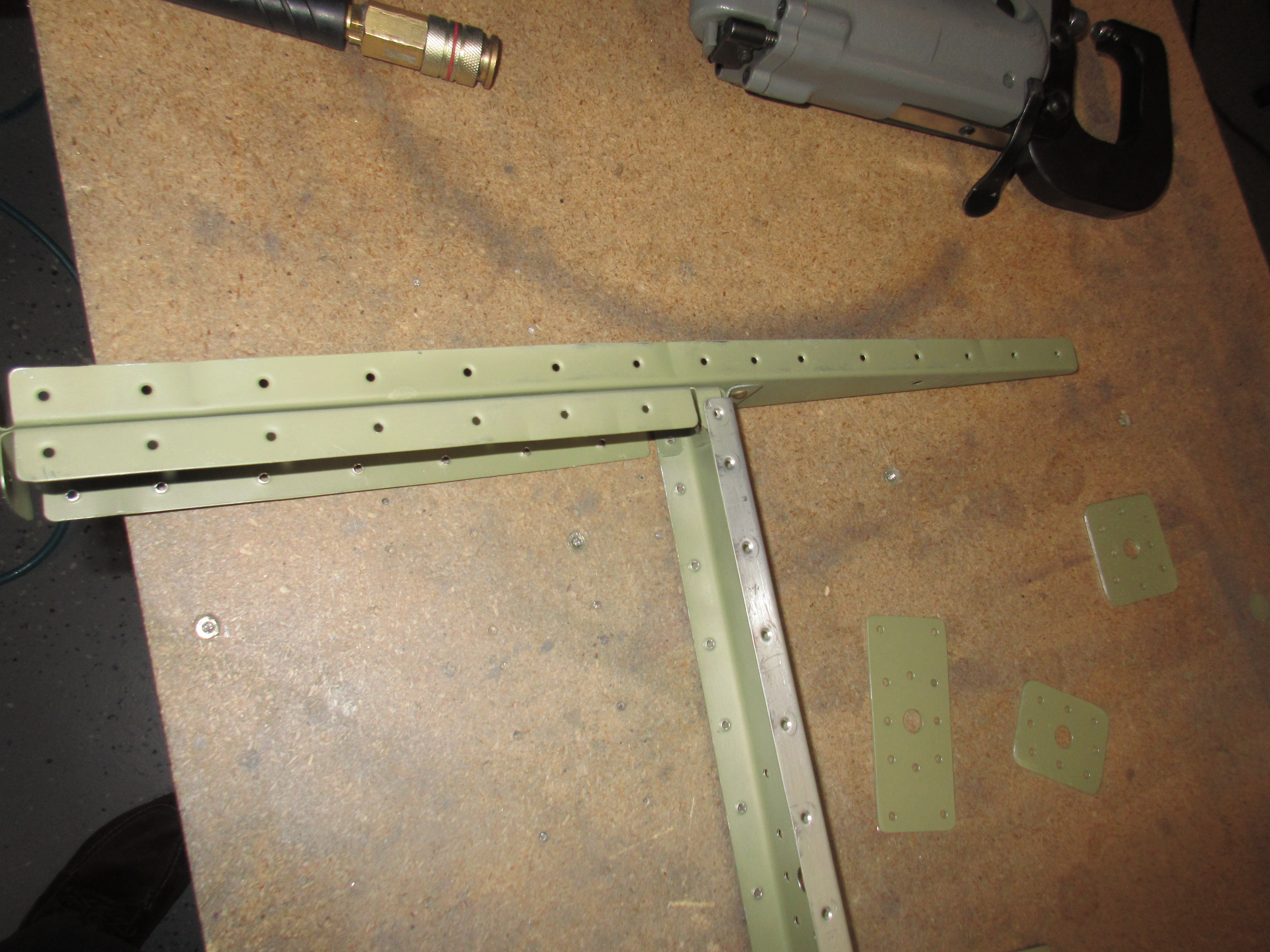
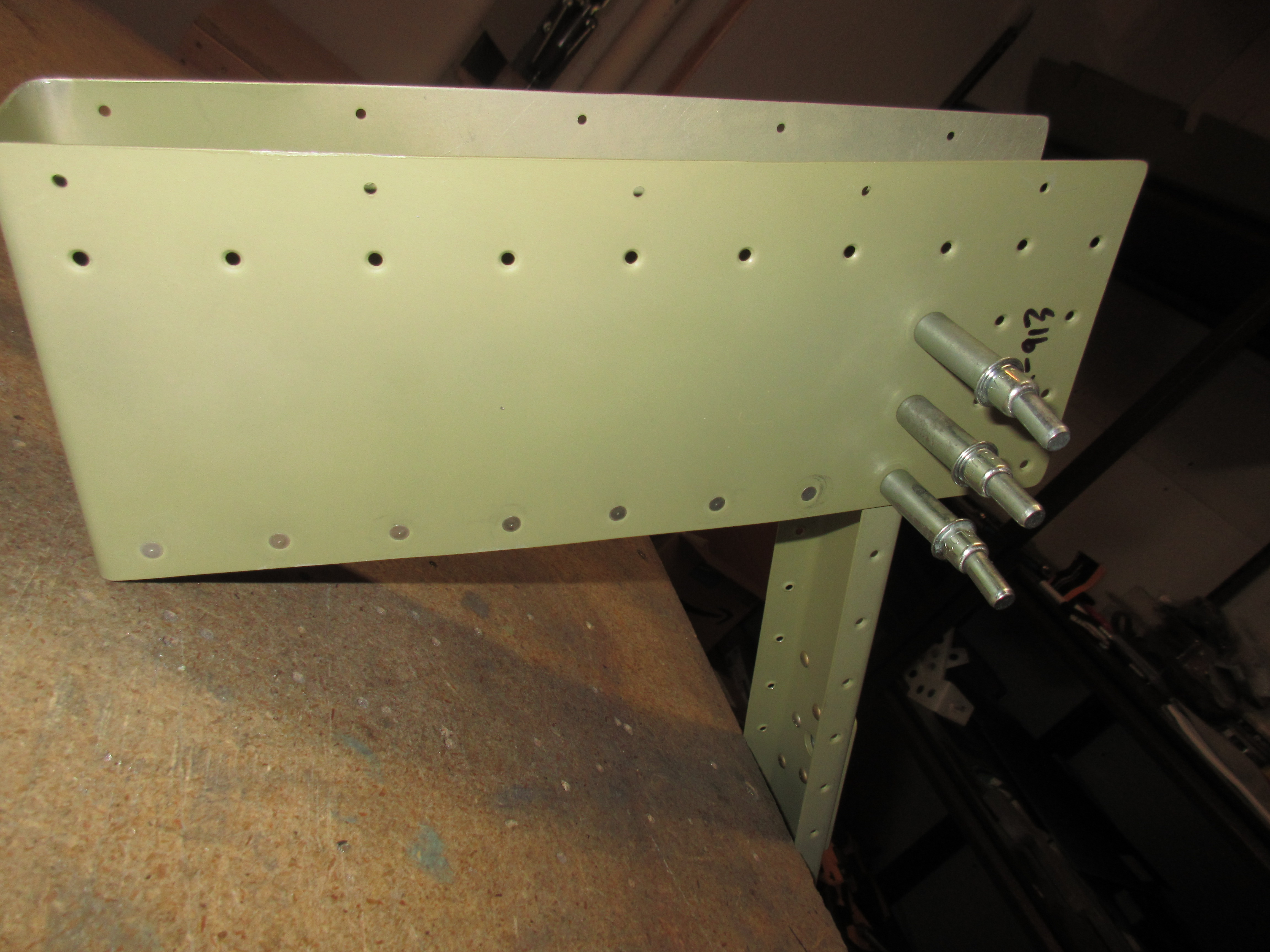
After taking short break from the priming session, I dug back into riveting together the right elevator skeleton.  This will give the primer on those doublers some time to dry. AKZO dries super quick, so by the time I get ready for them they should be ready for me 🙂   Per the plans, Vans has us start out by riveting together the E-703 and E-704 ribs which creates the counterbalance assembly  This goes easy enough with a squeezer and some AN470AD4-4 rivets.

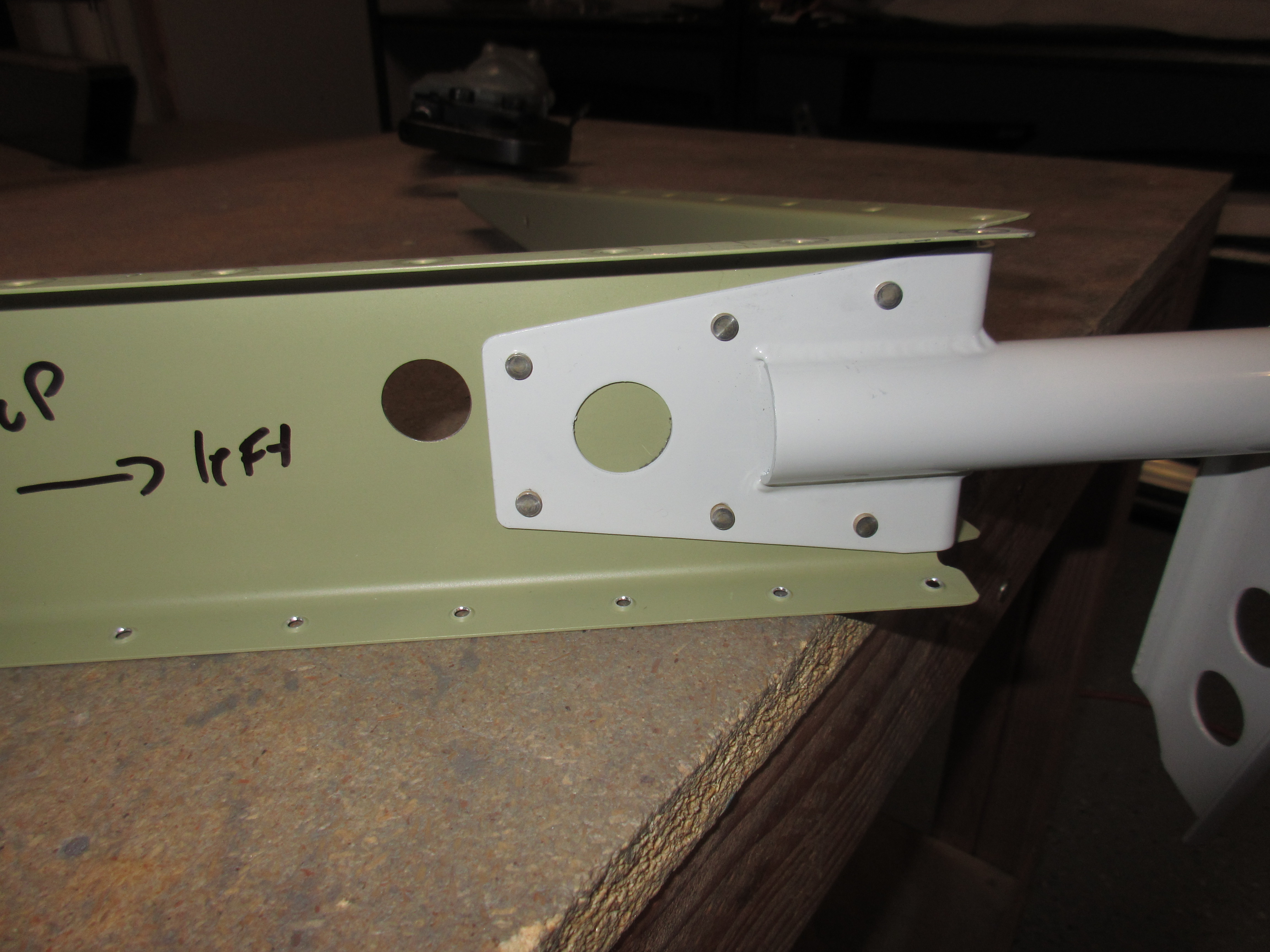
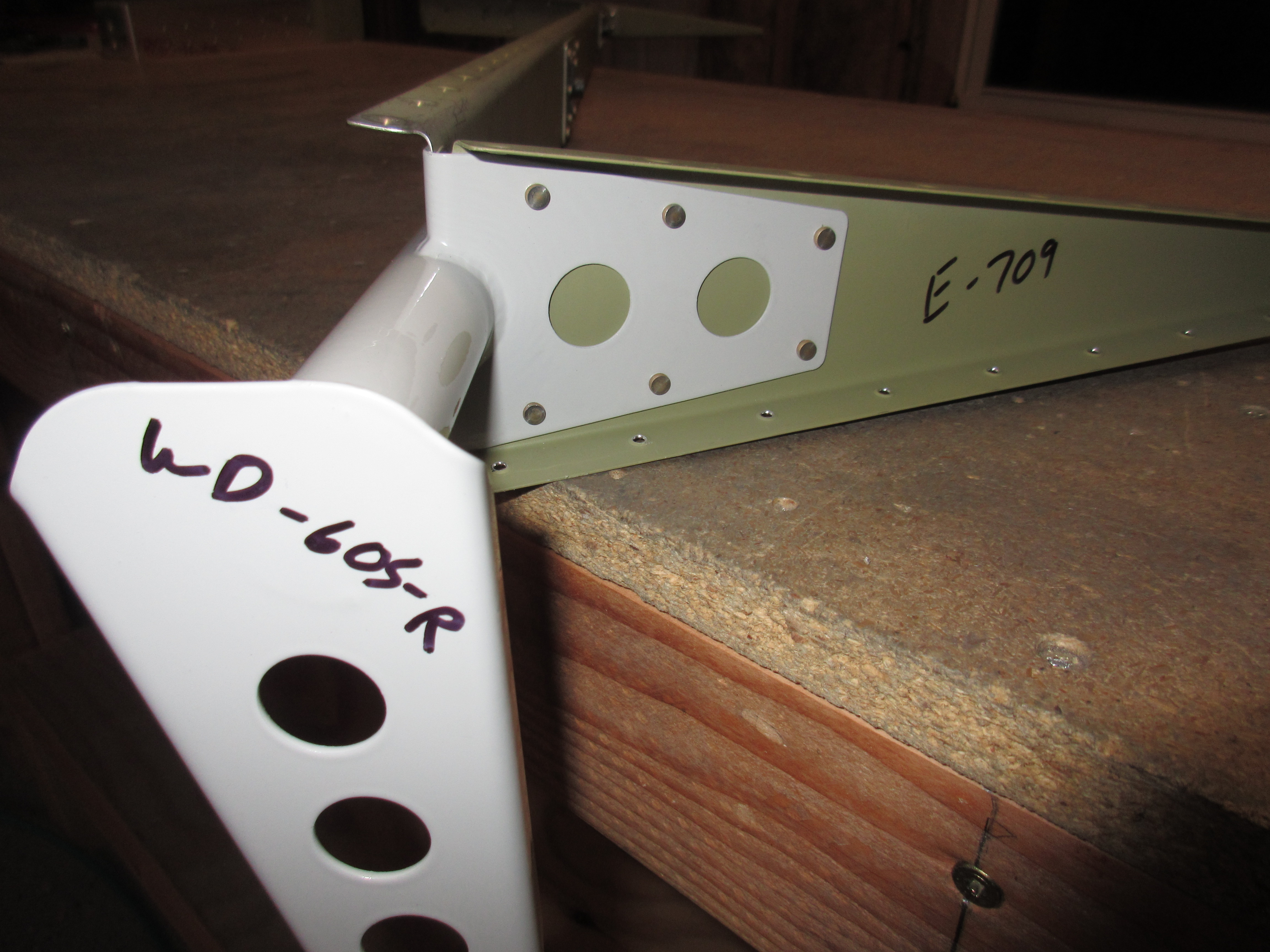
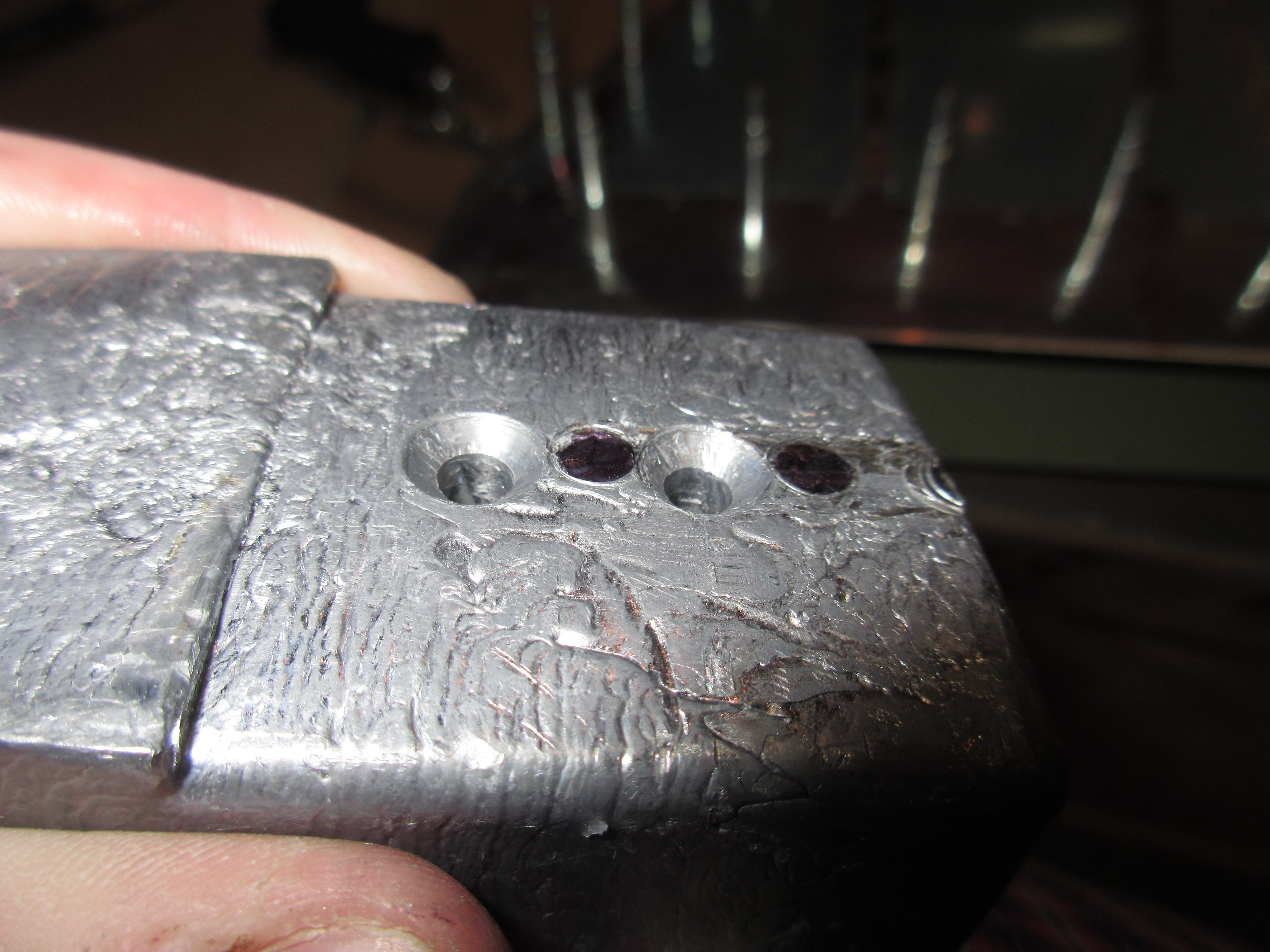
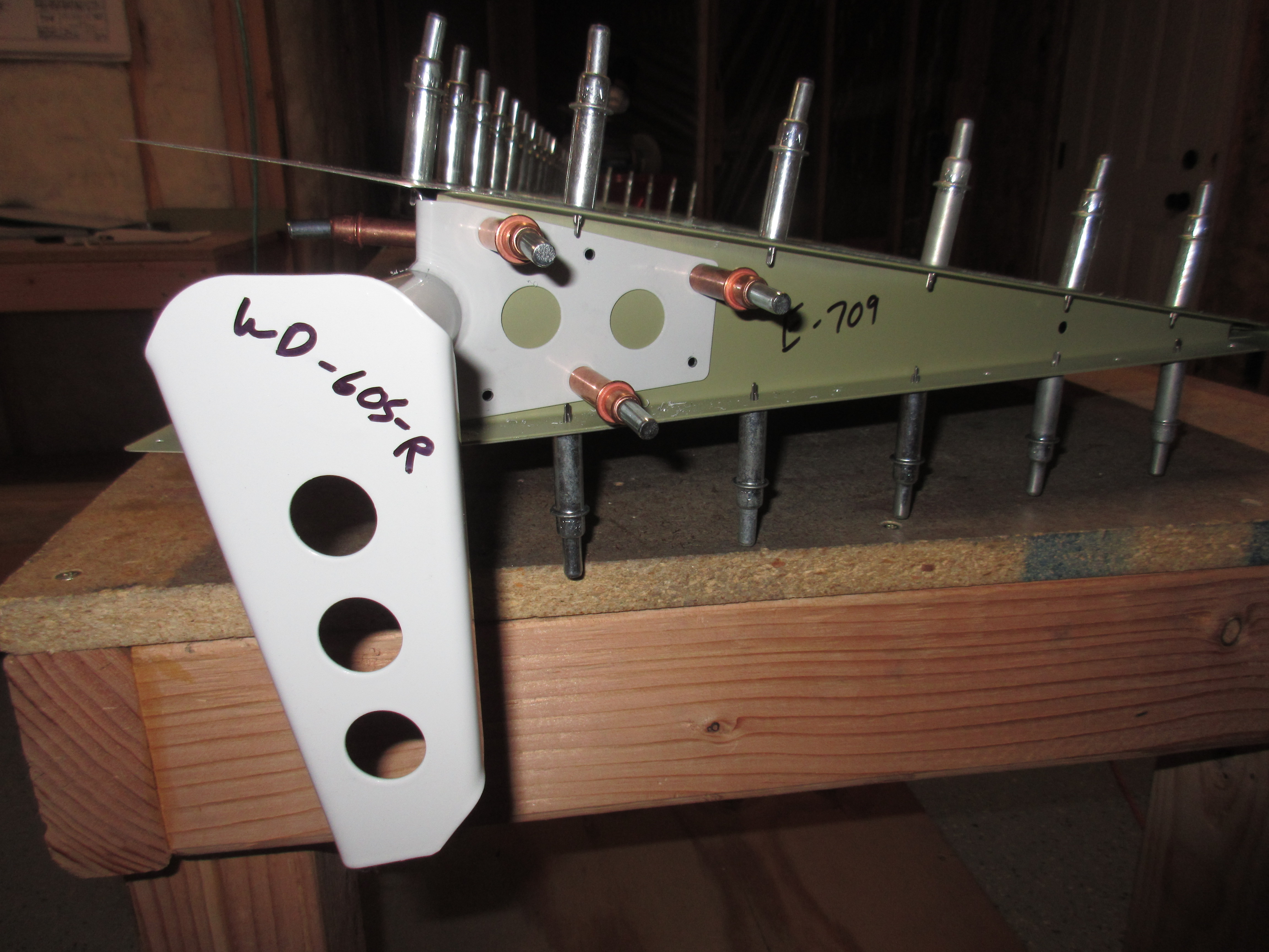
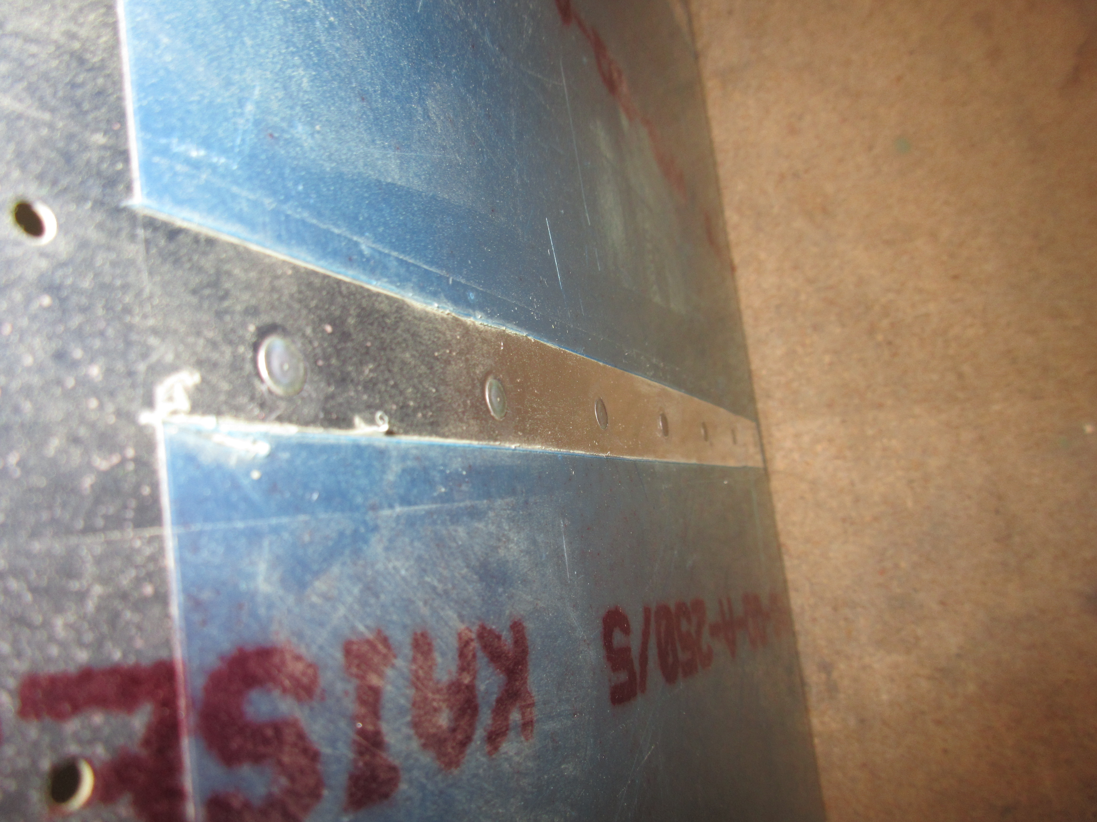
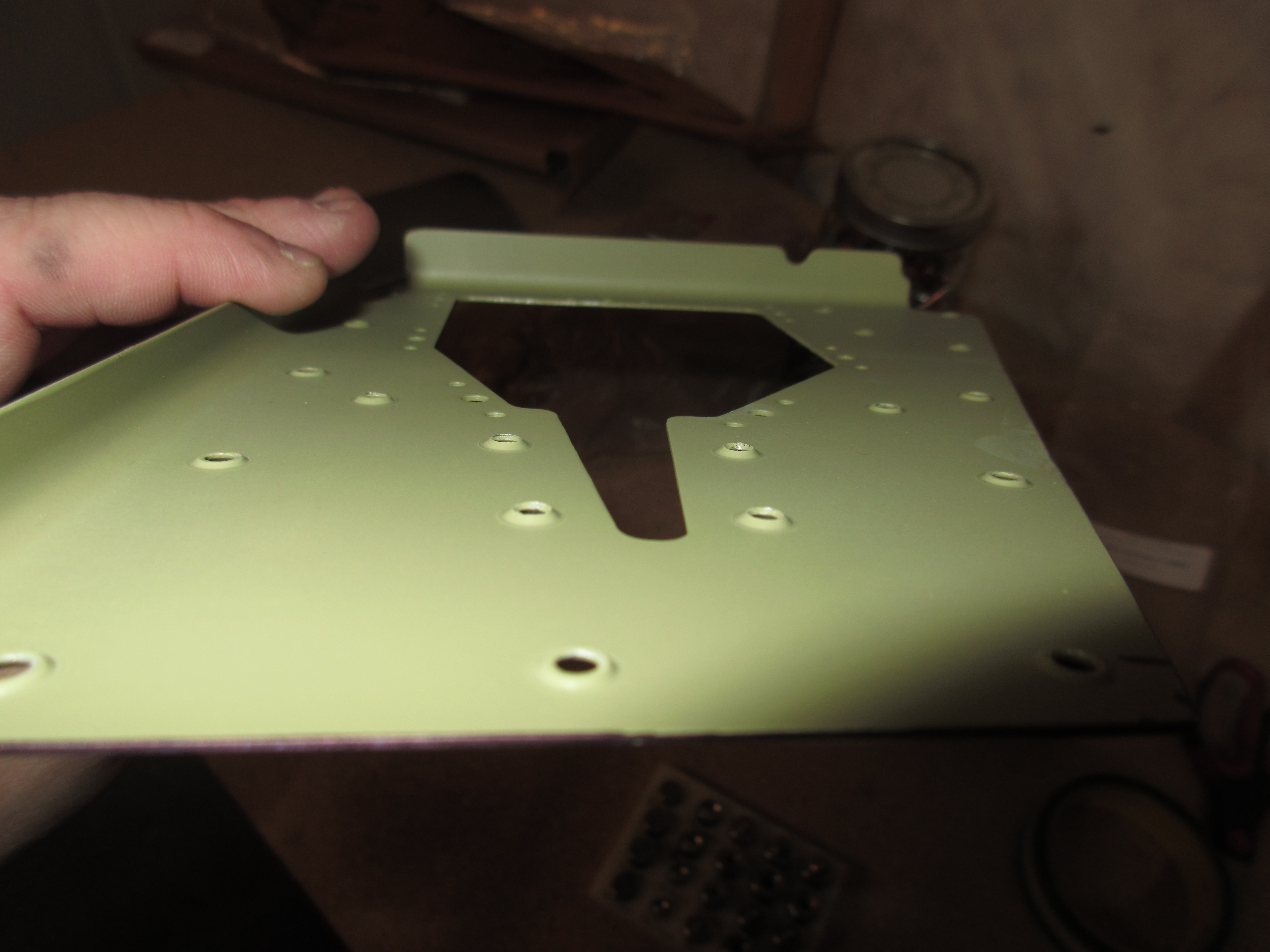
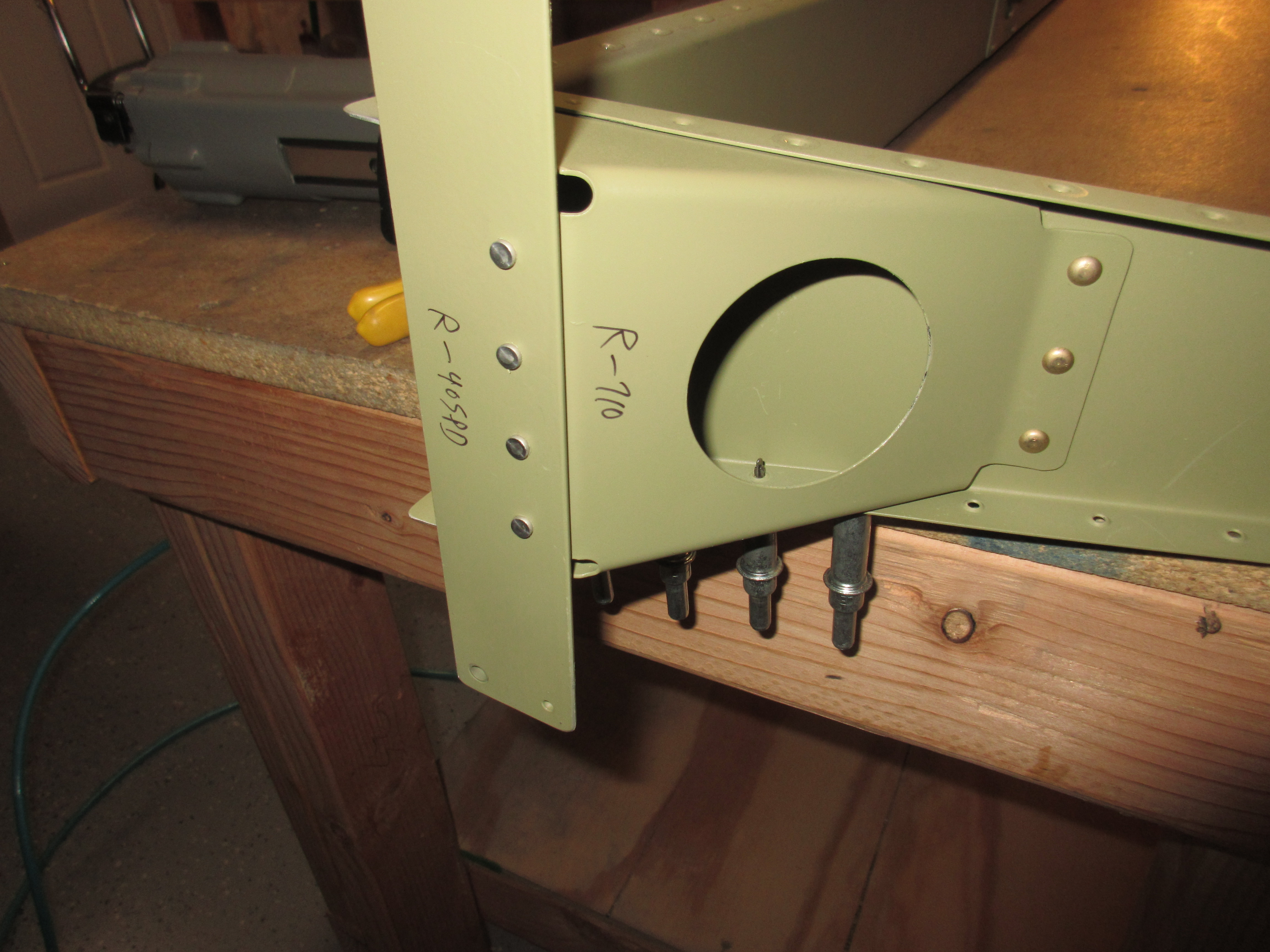
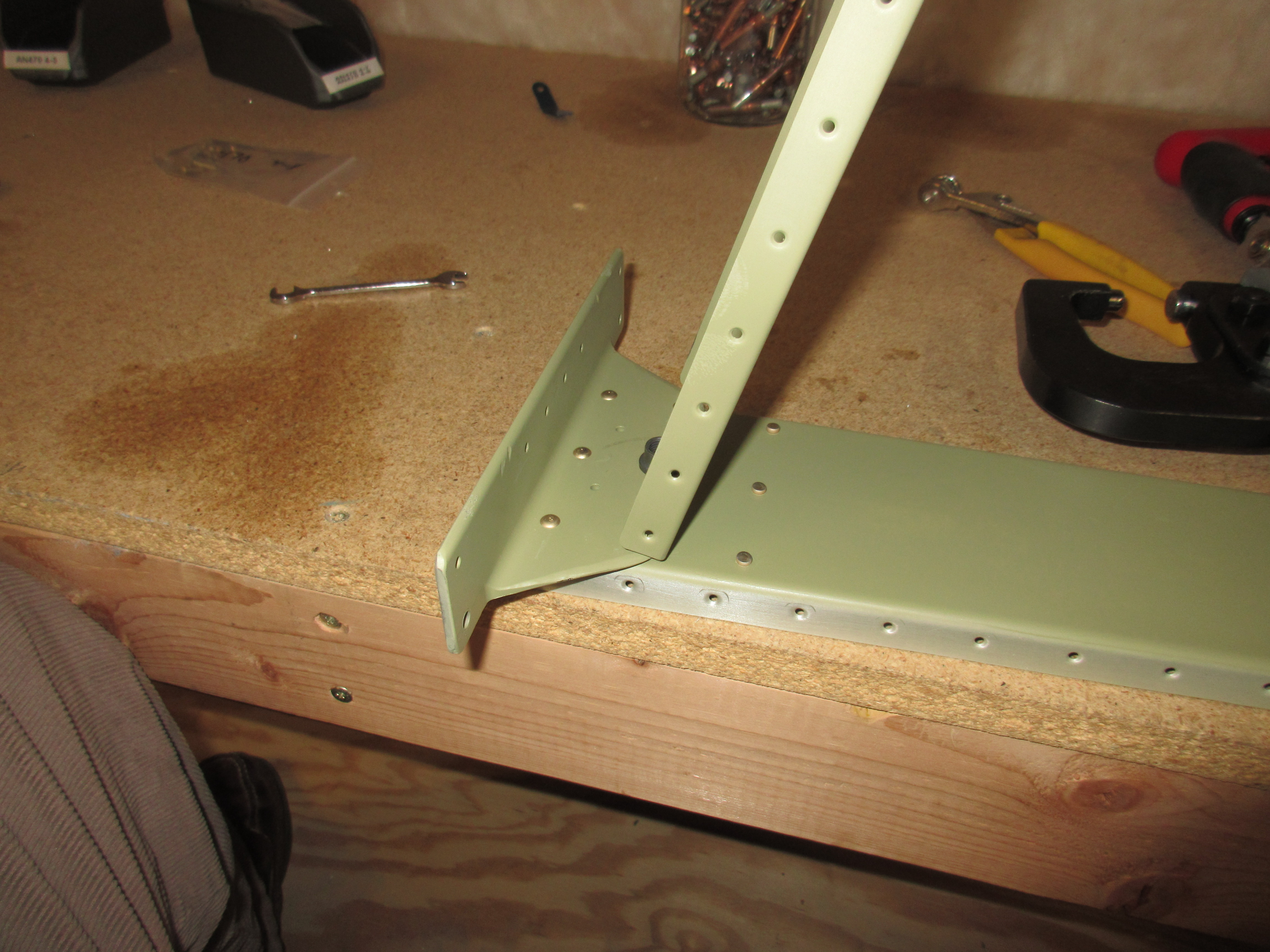
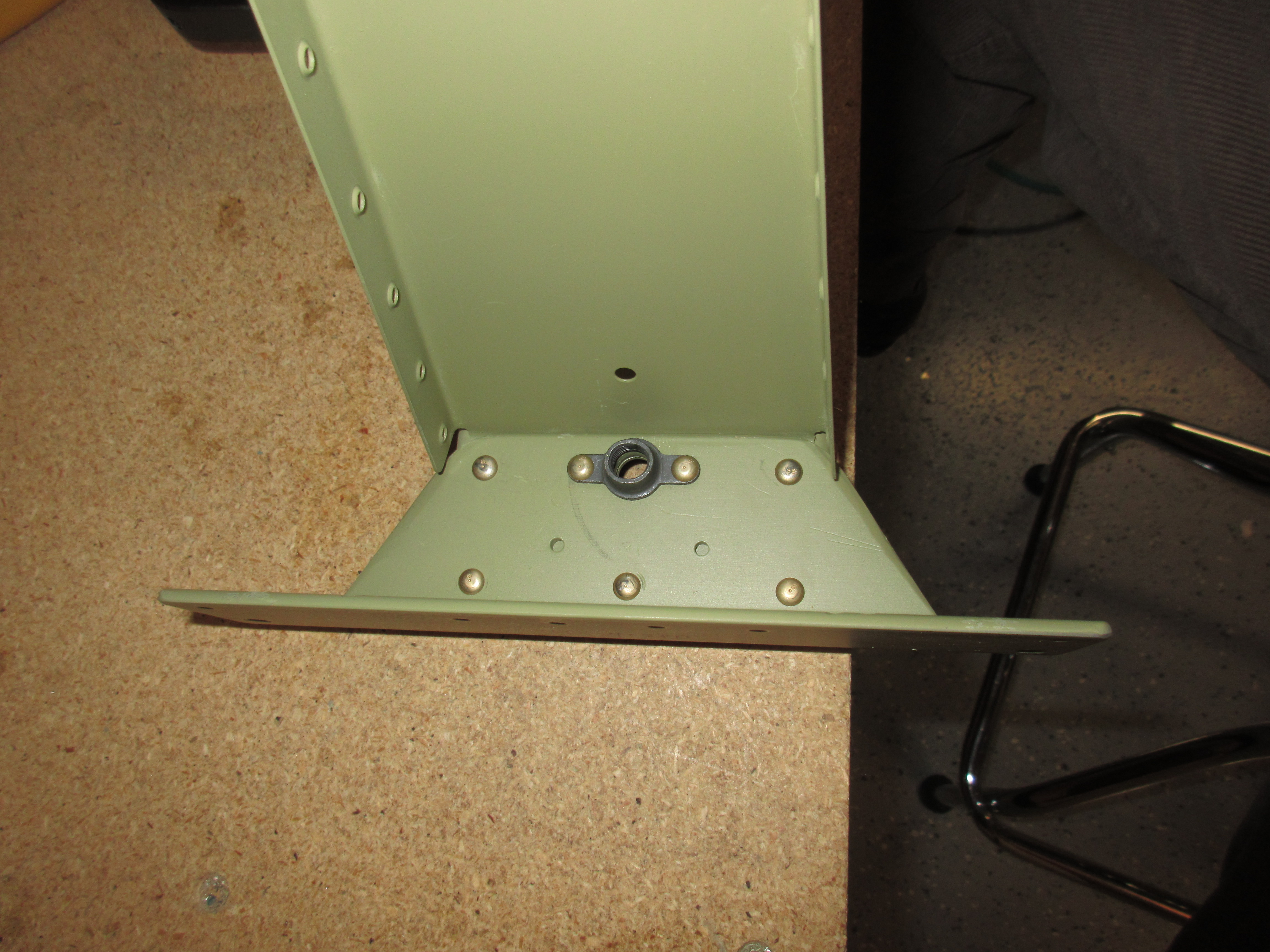
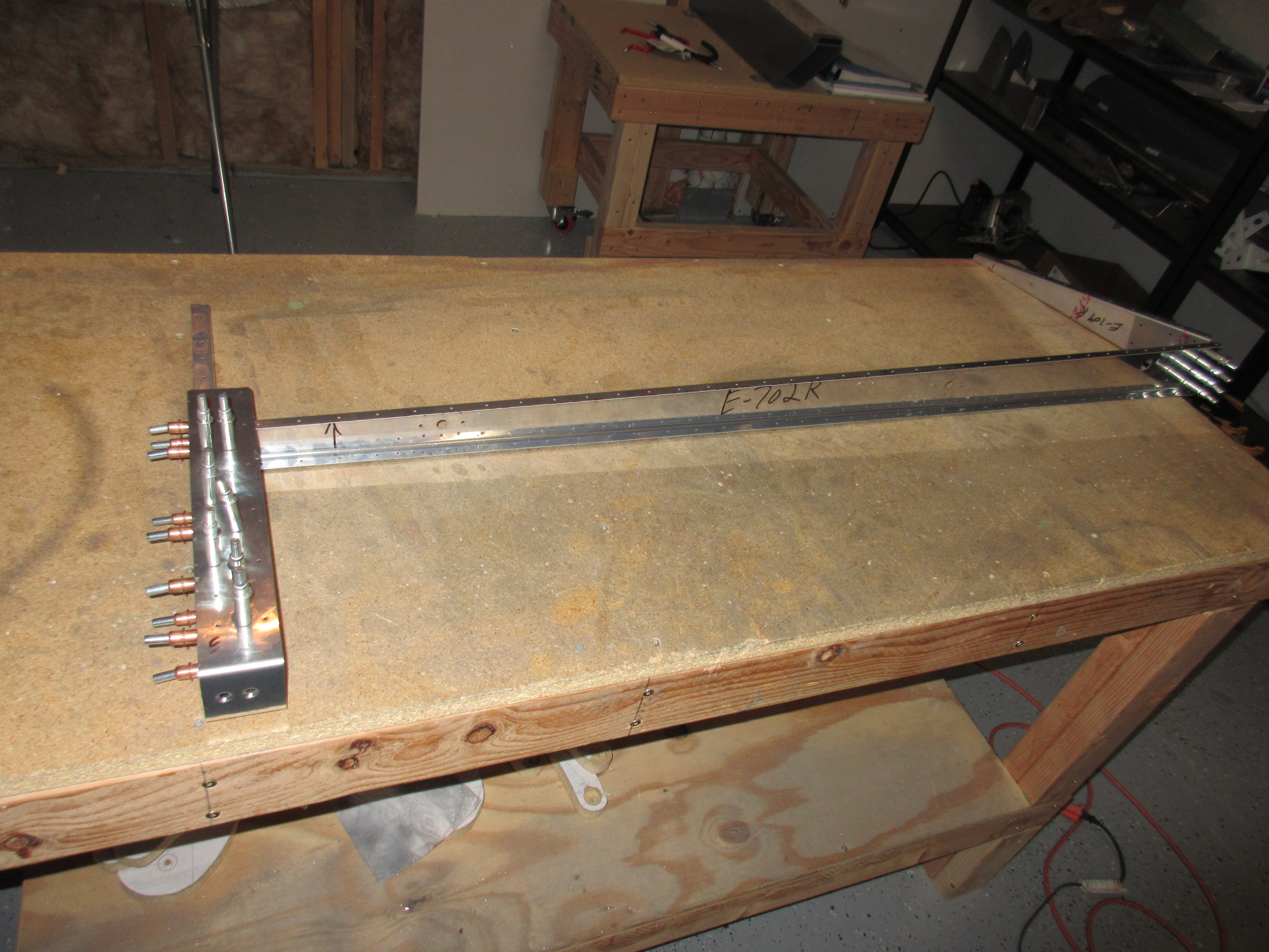
Next up the plans has us rivet the E-709 end rib to the E-702 spar.  I had to take caution here, because we use AN426AD3-4 rivets, which need to be dimpled and sit flush on the front side of the spar so that the WD-605-1-R elevator horn will sit flush against the spar.  I was able to set these rivets with the flush set in my squeezer and they ended up nice and flush against the spar.

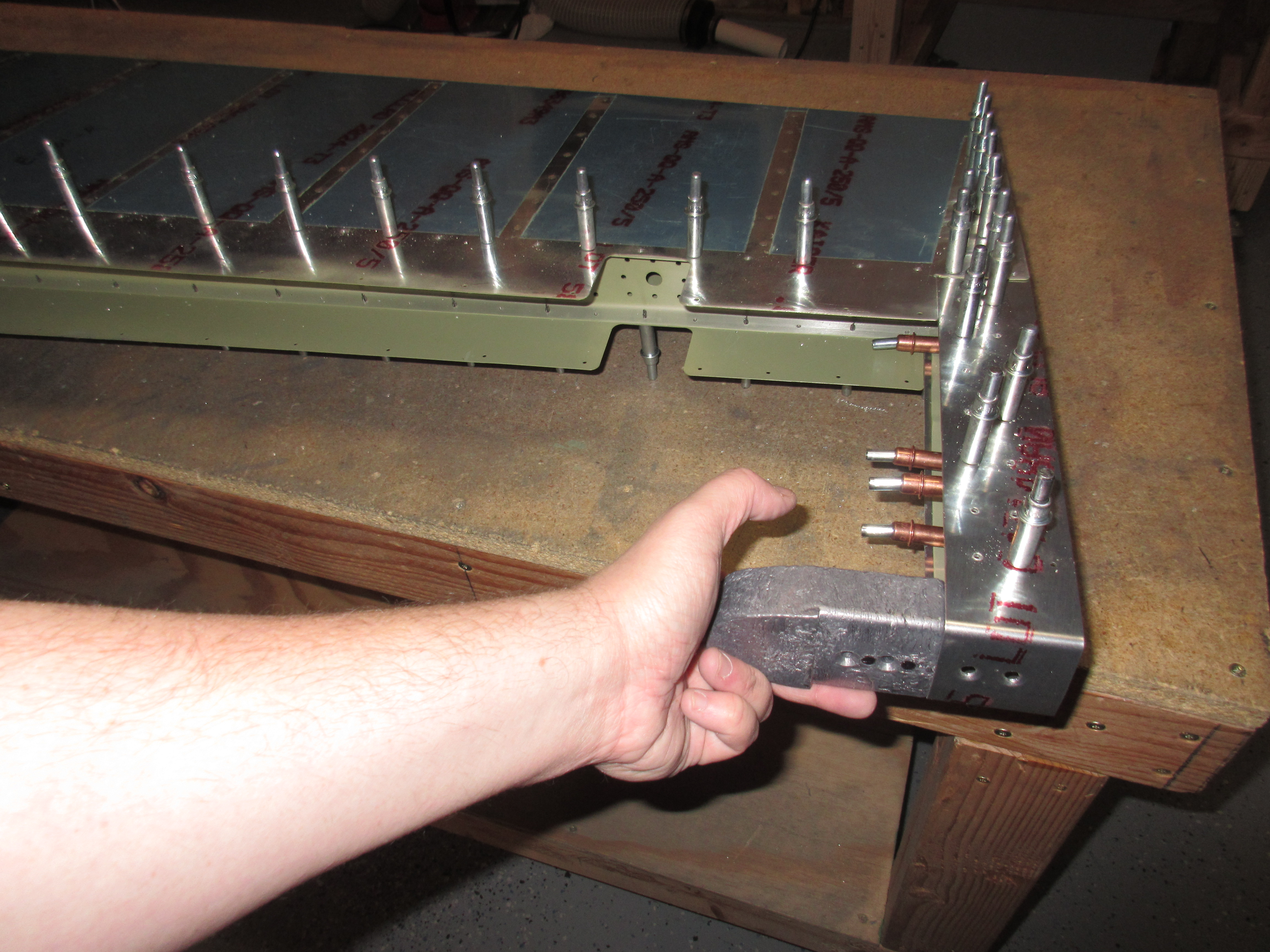
Then the plans has us rivet on the E-703/704 assembly to the E-702 spar.  This is where things got frustrating.  I was able to set the two rivets for the E-703 end rib with the squeezer. However, the two rivets for the E-704 were in a much tighter spot and I couldn’t get to then with the squeezer.  So, I drug out the rivet gun and bucking bar, but the straight 1/8 rivet set would not line up with the shop head of the rivet because of the gun body, so I had to use the offset 1/8 rivet set.  The first rivet I was able to set pretty well with the gun and bucking bar.  The second one?  Yeah, not so much.  I had to drill it out and try again.  Luckily, the second time went better than the first and I got the rivet set.

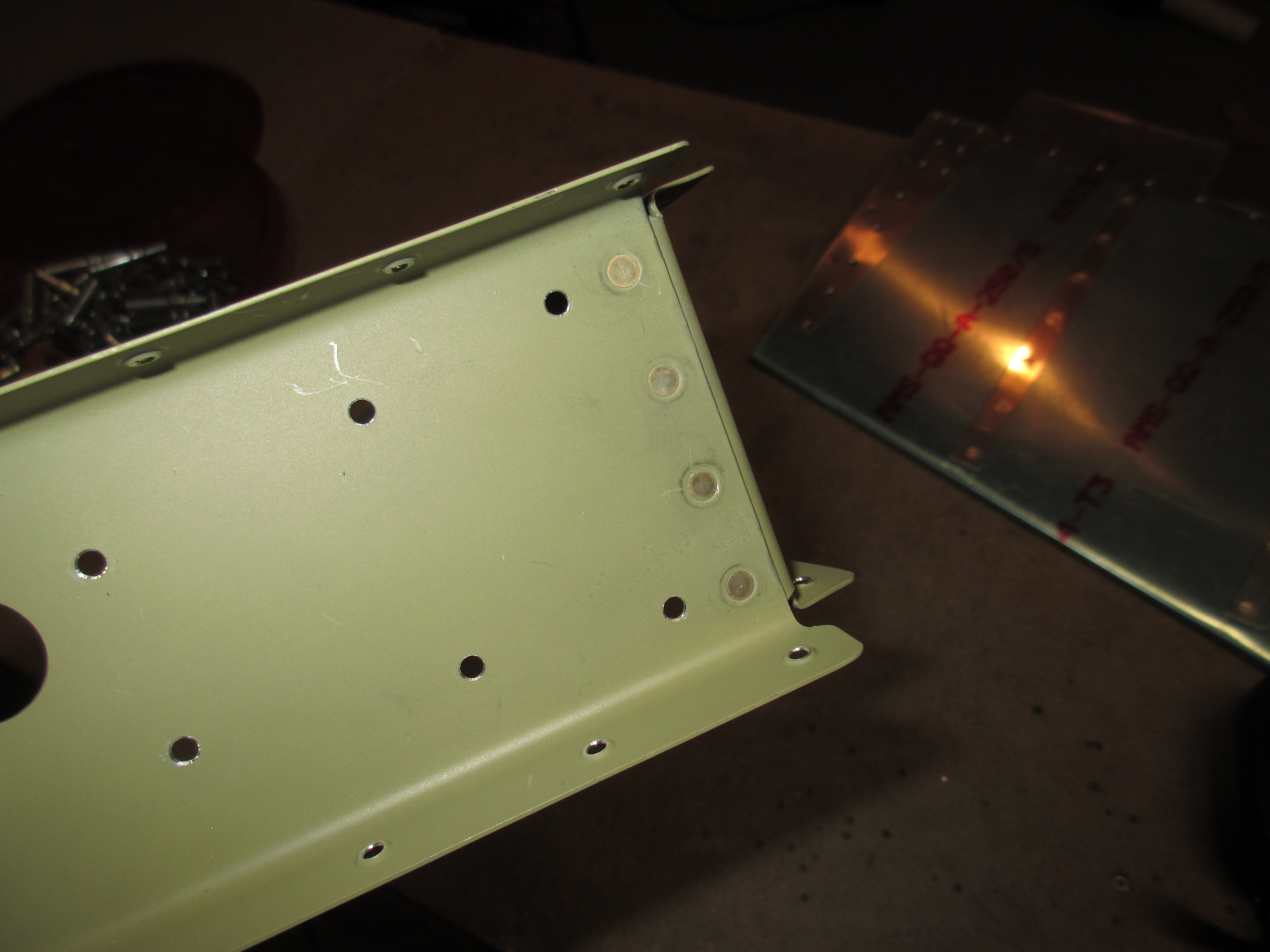
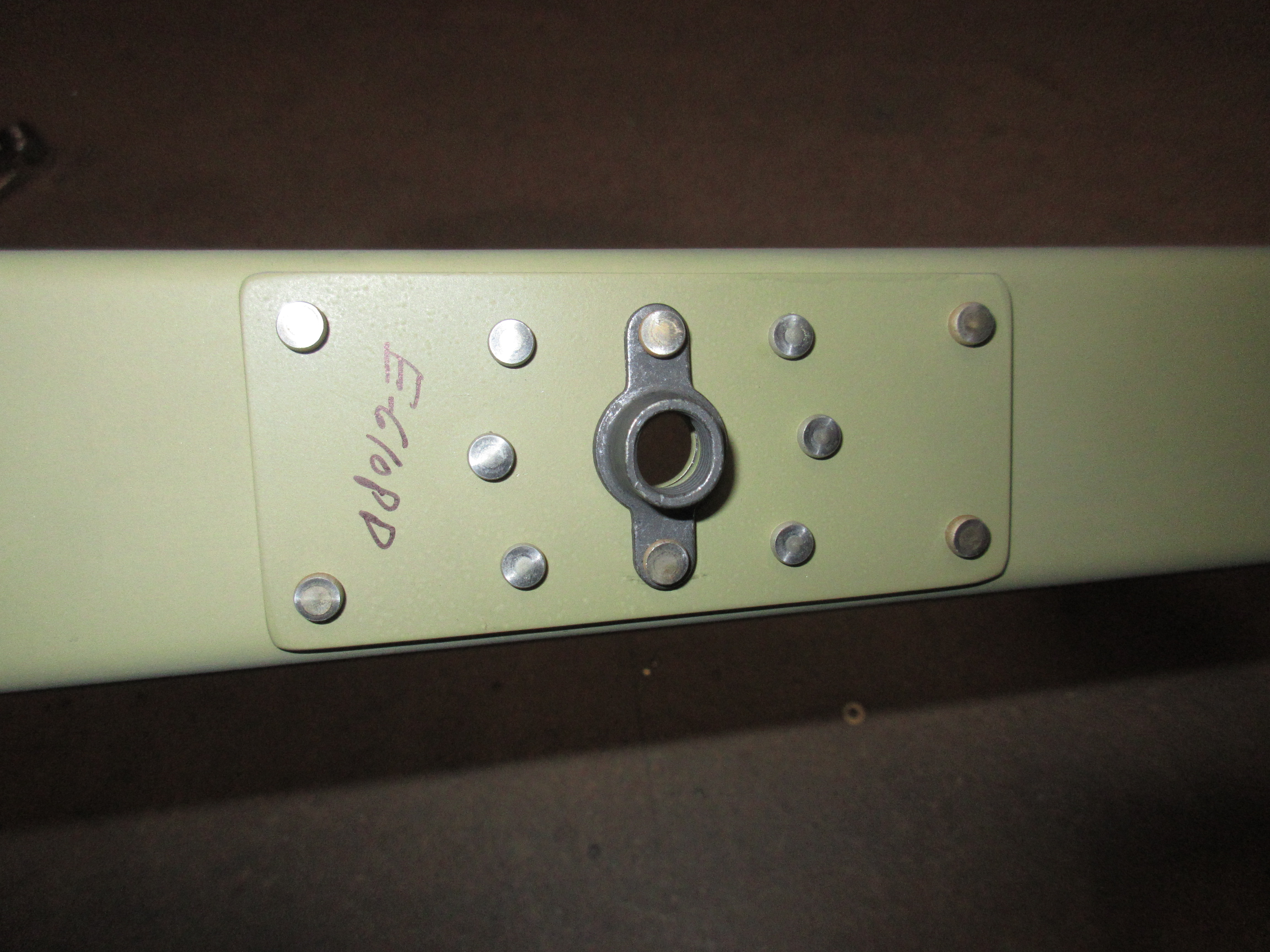
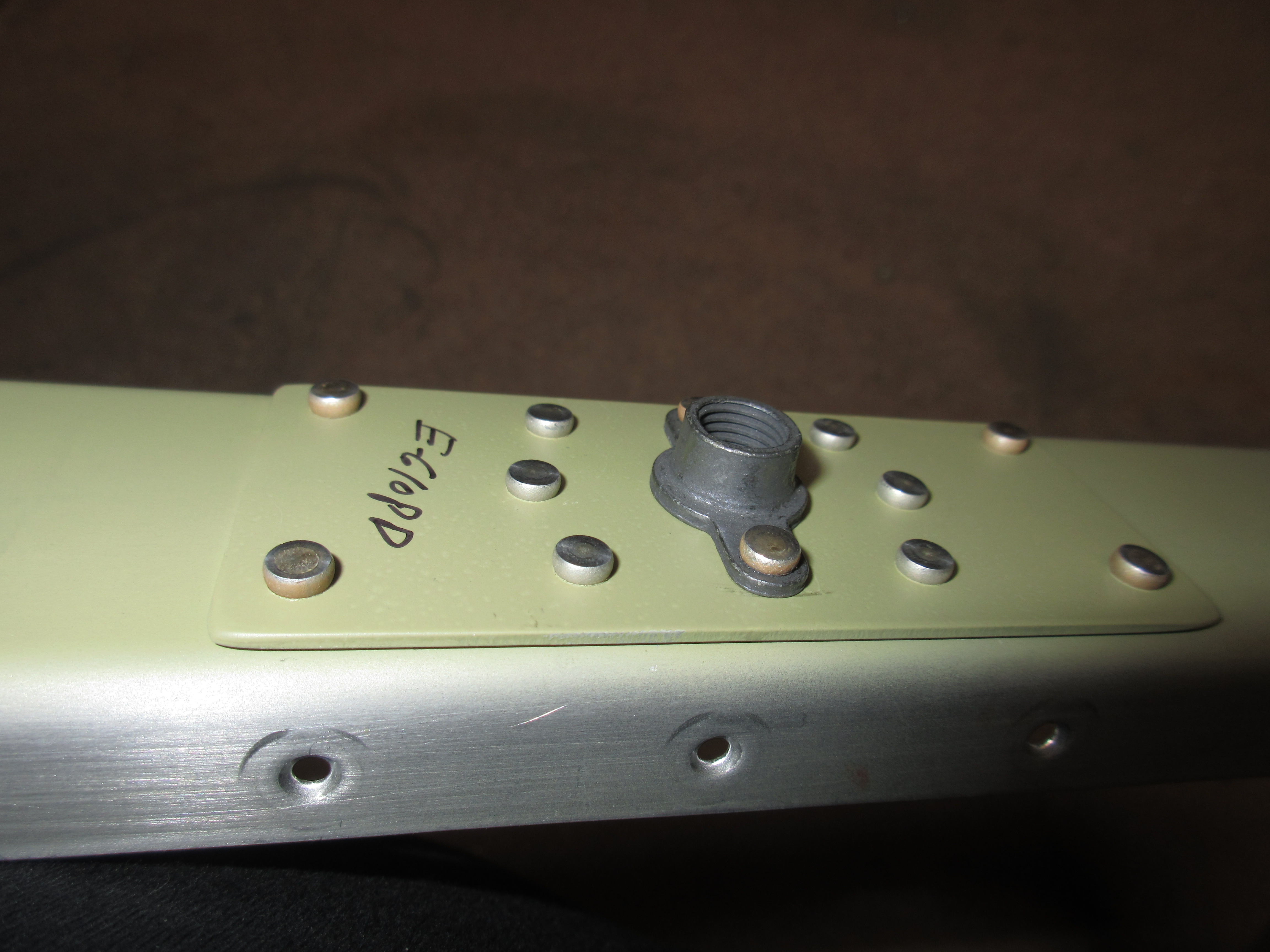
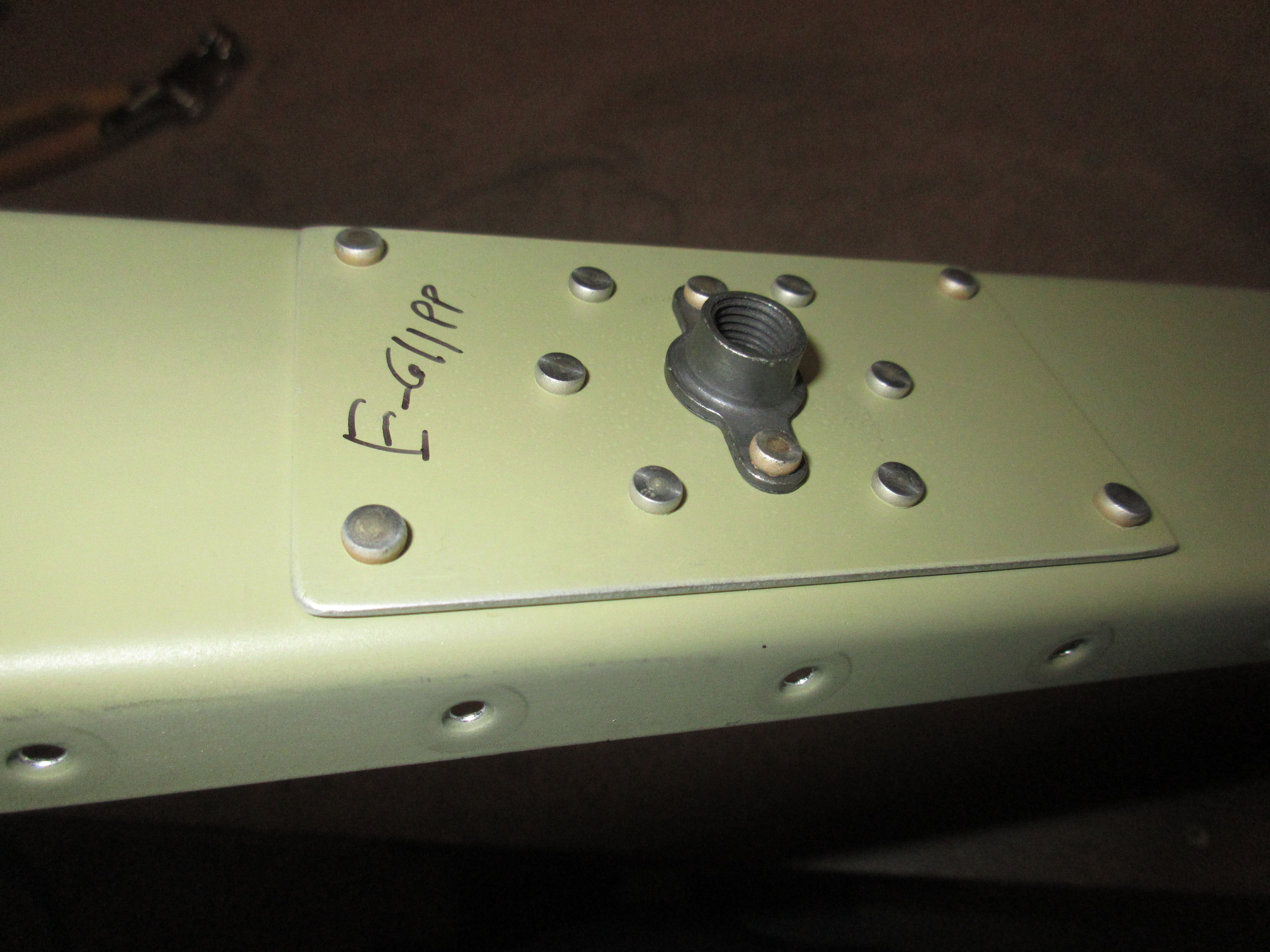
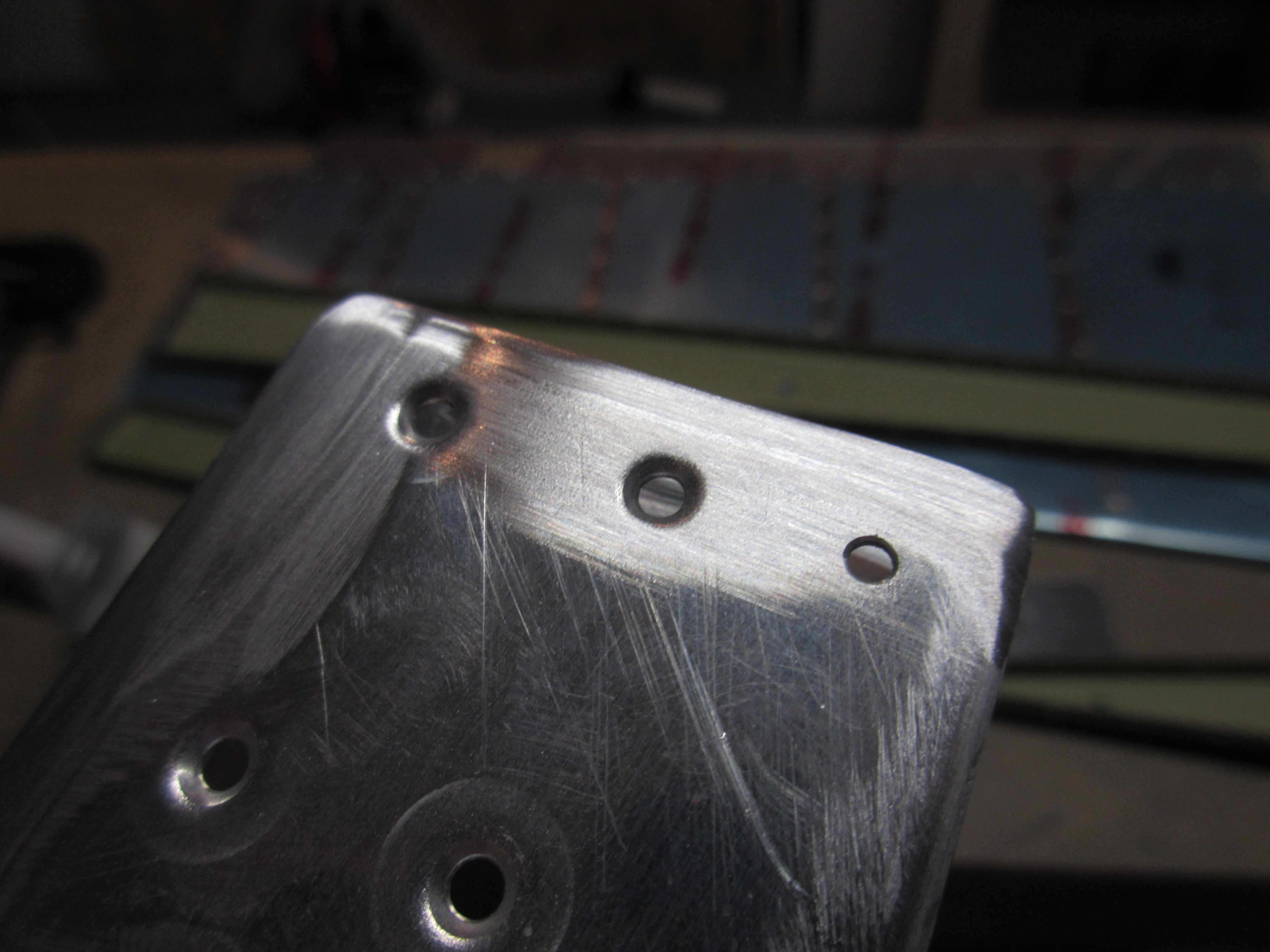
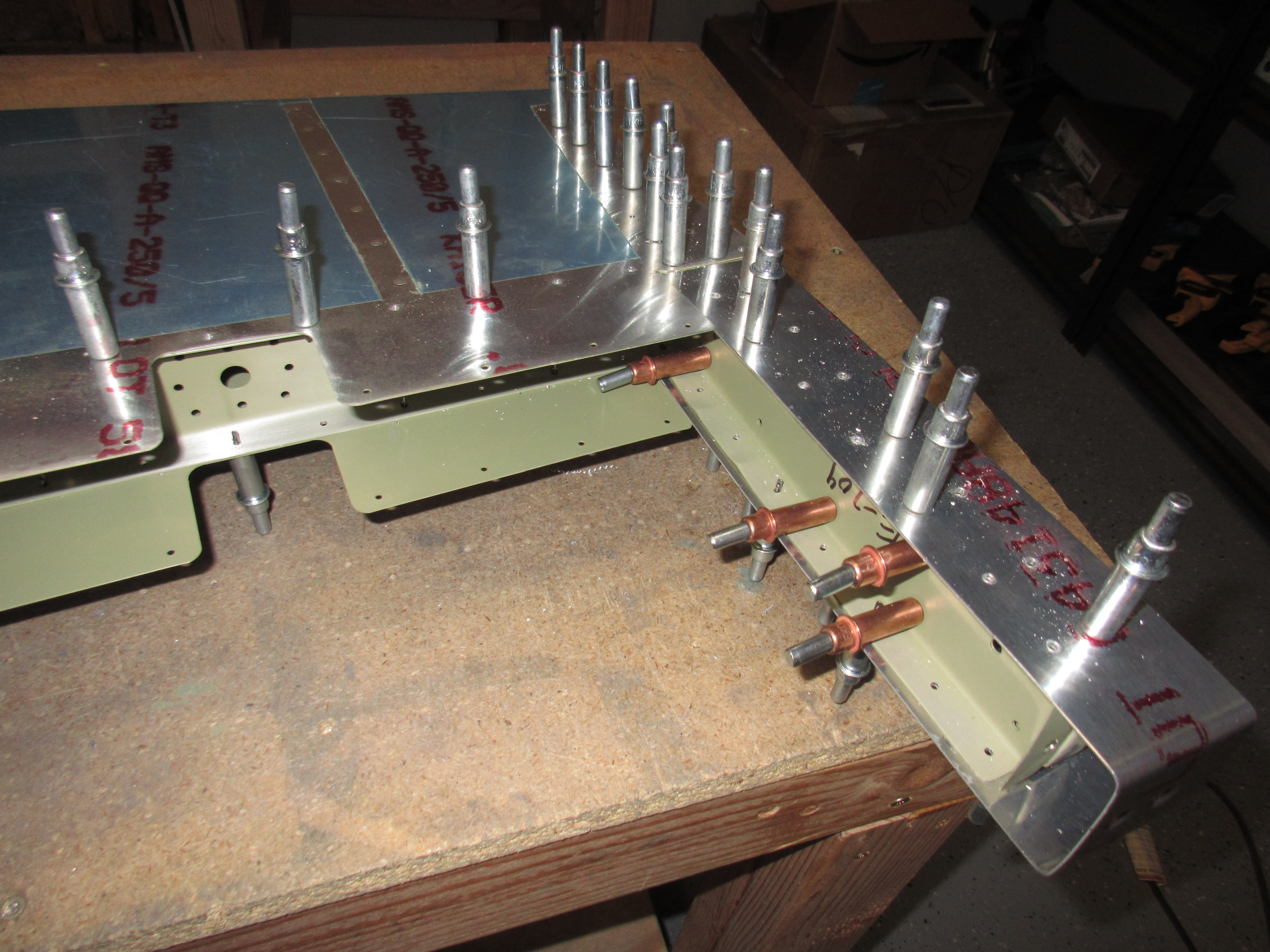
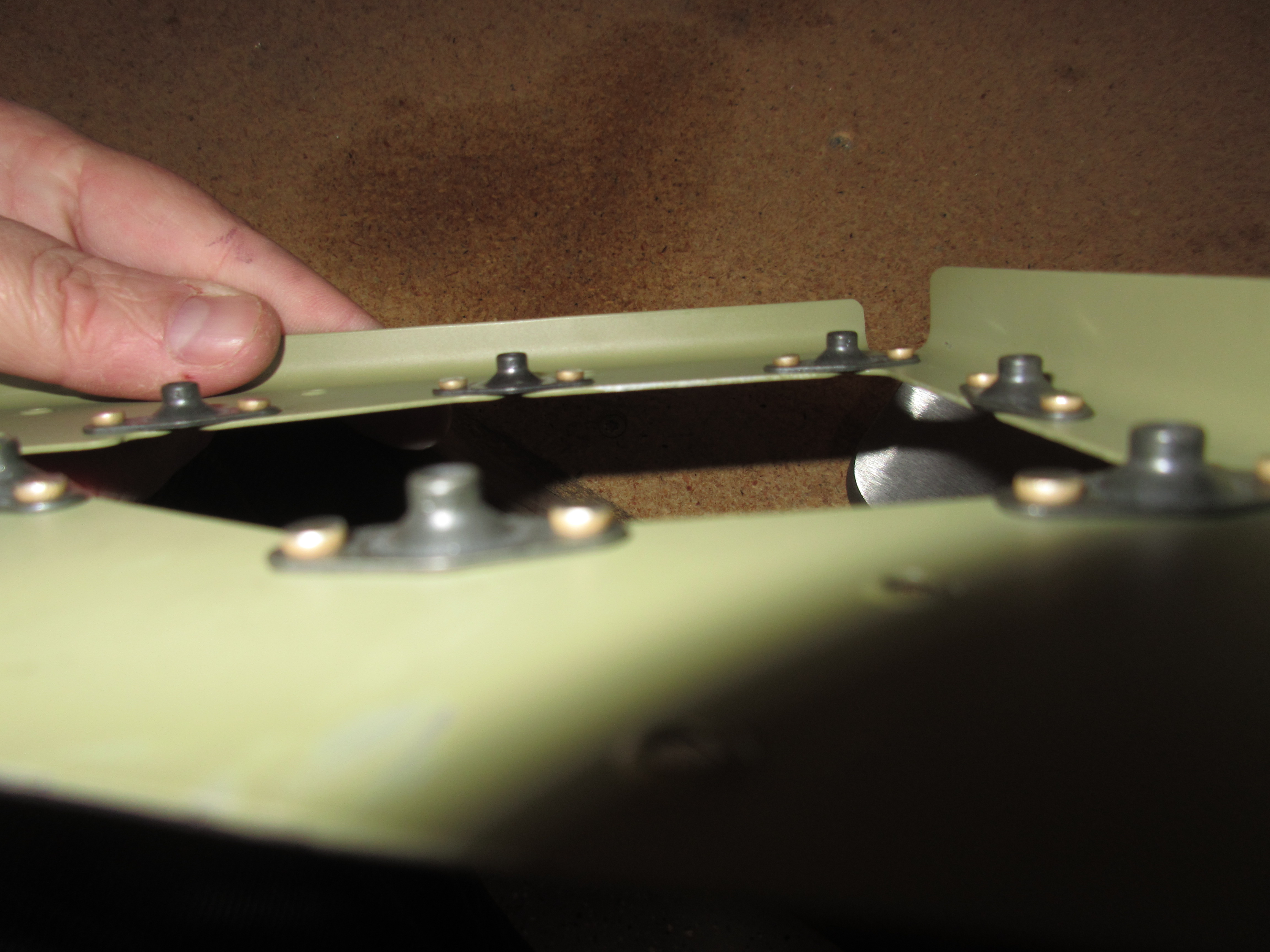
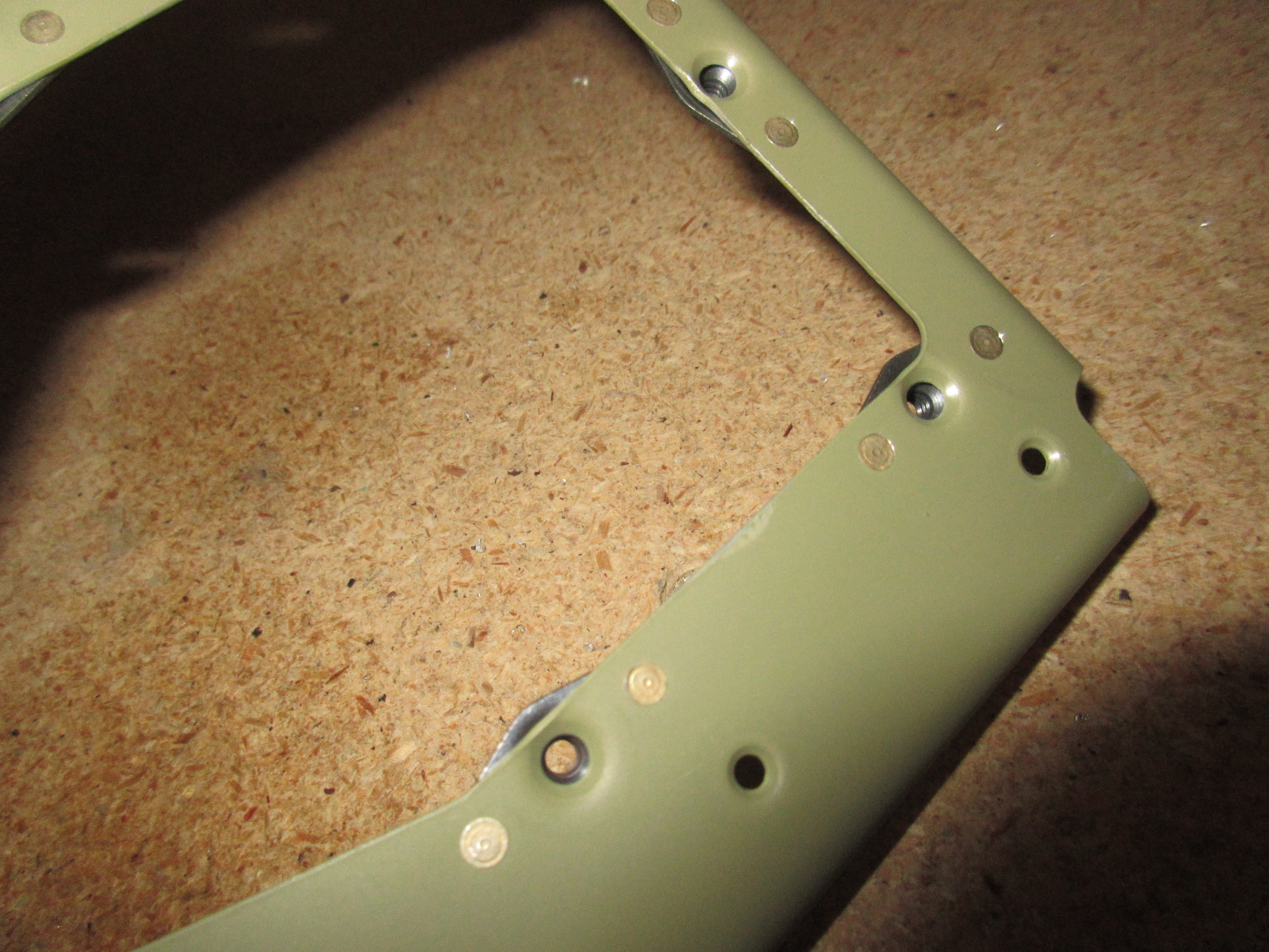
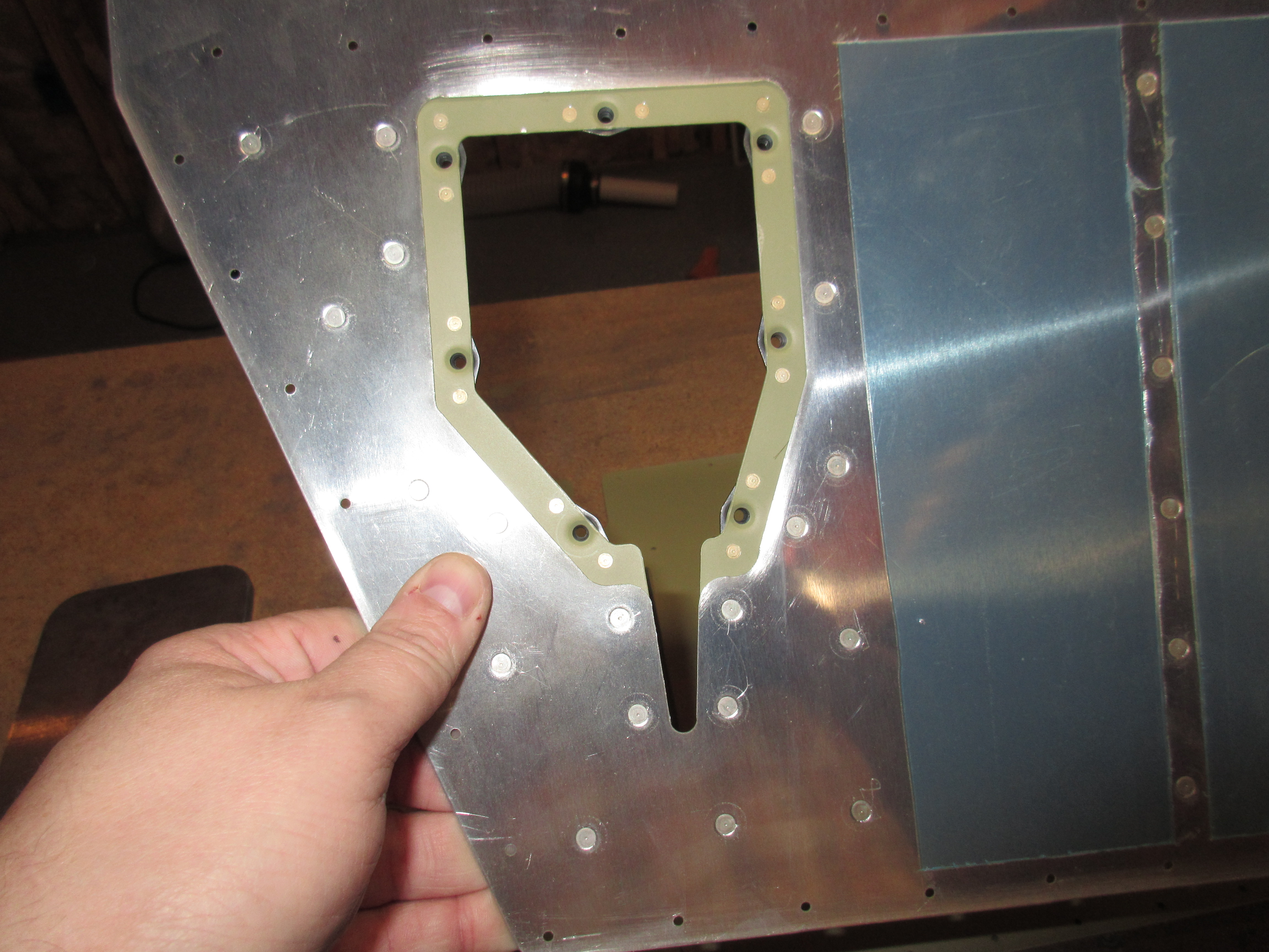
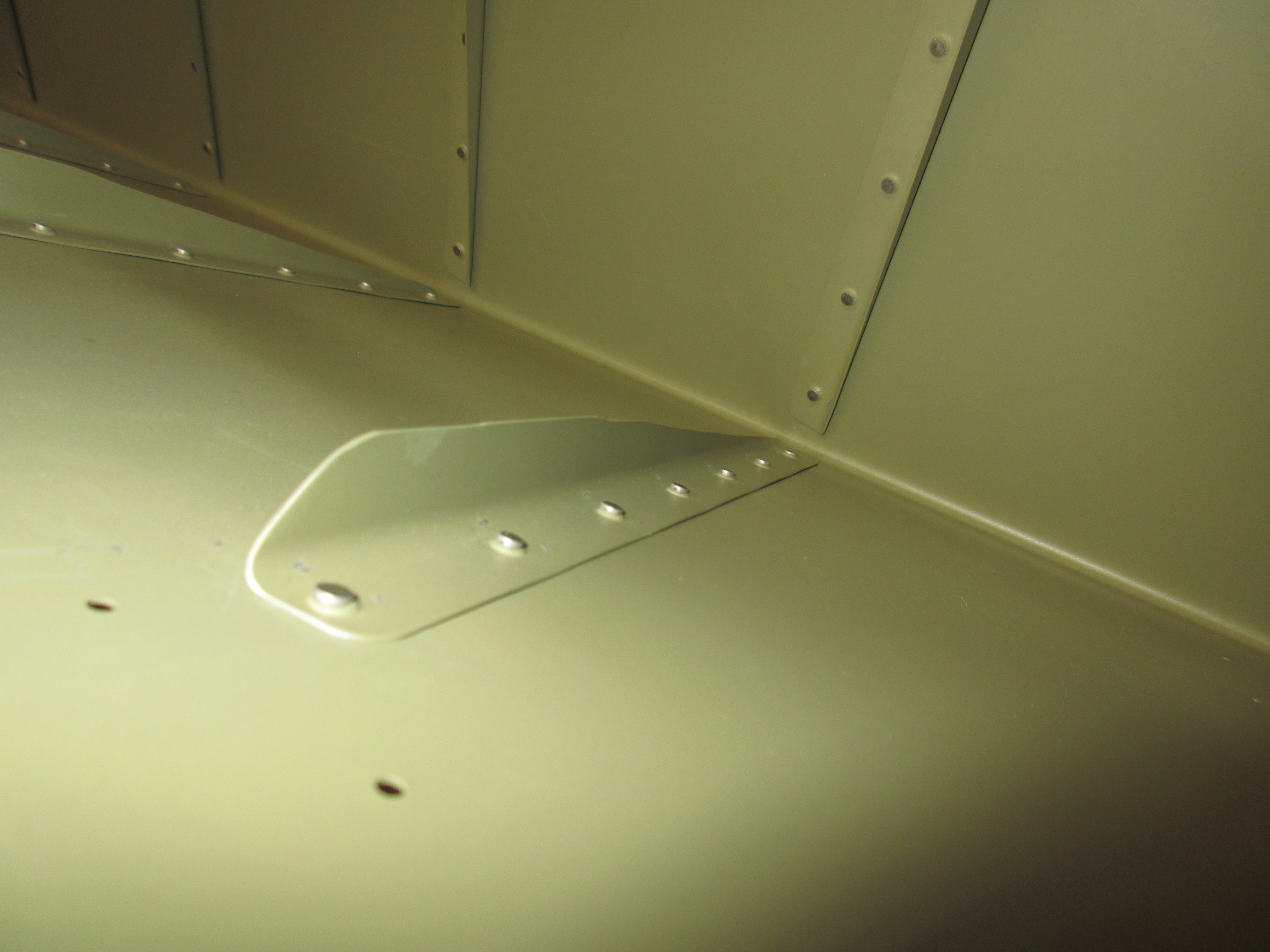
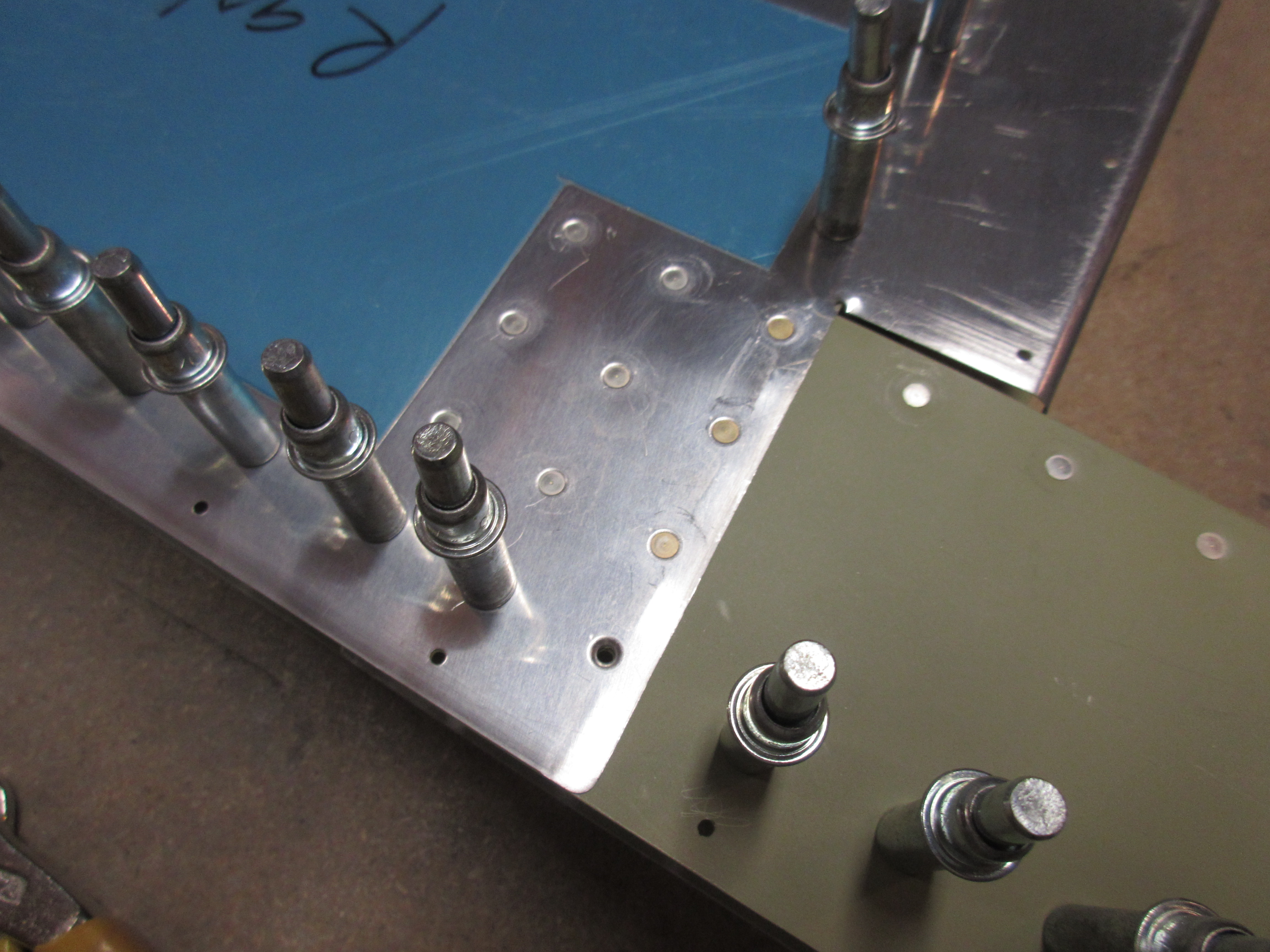
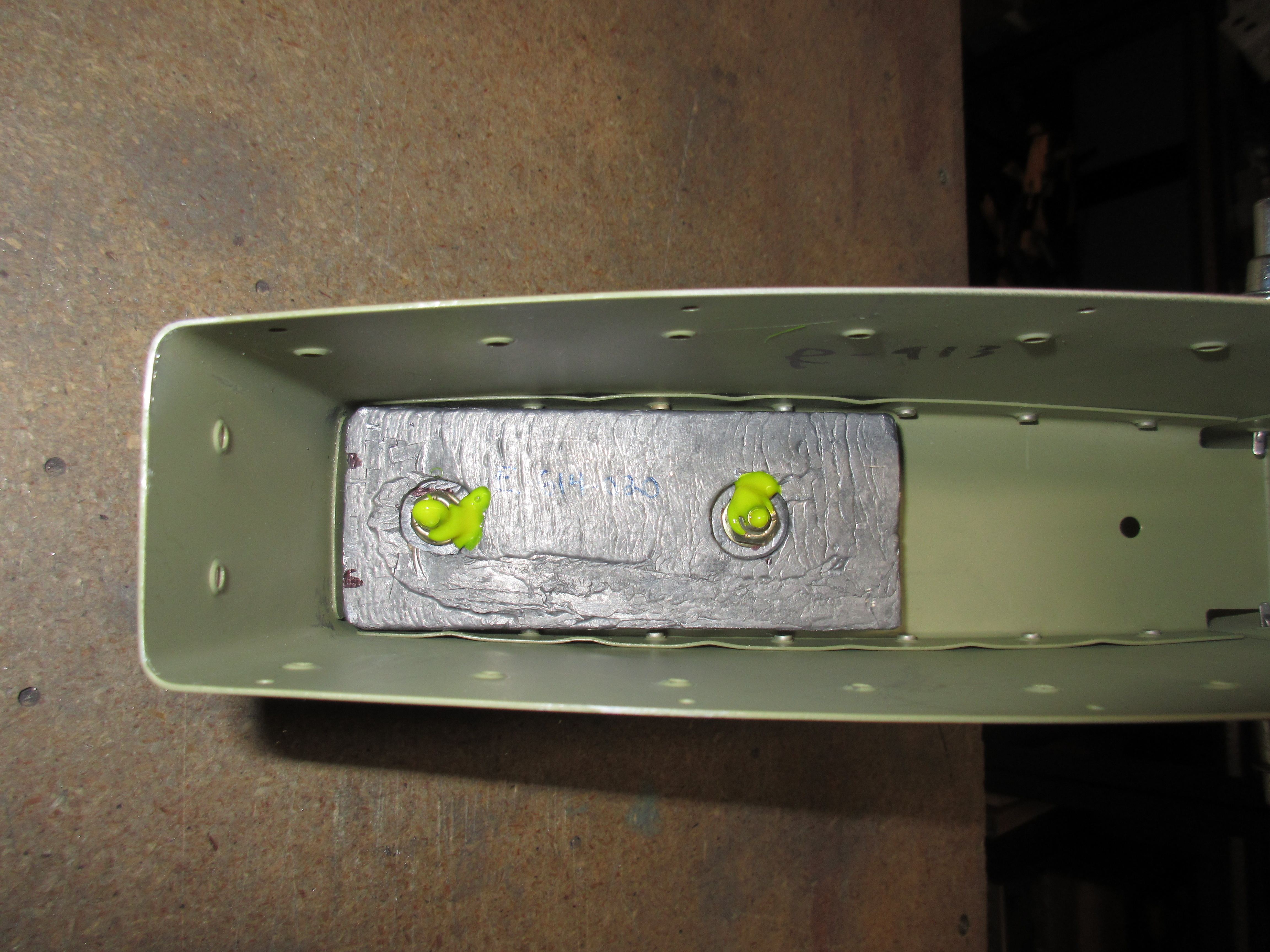
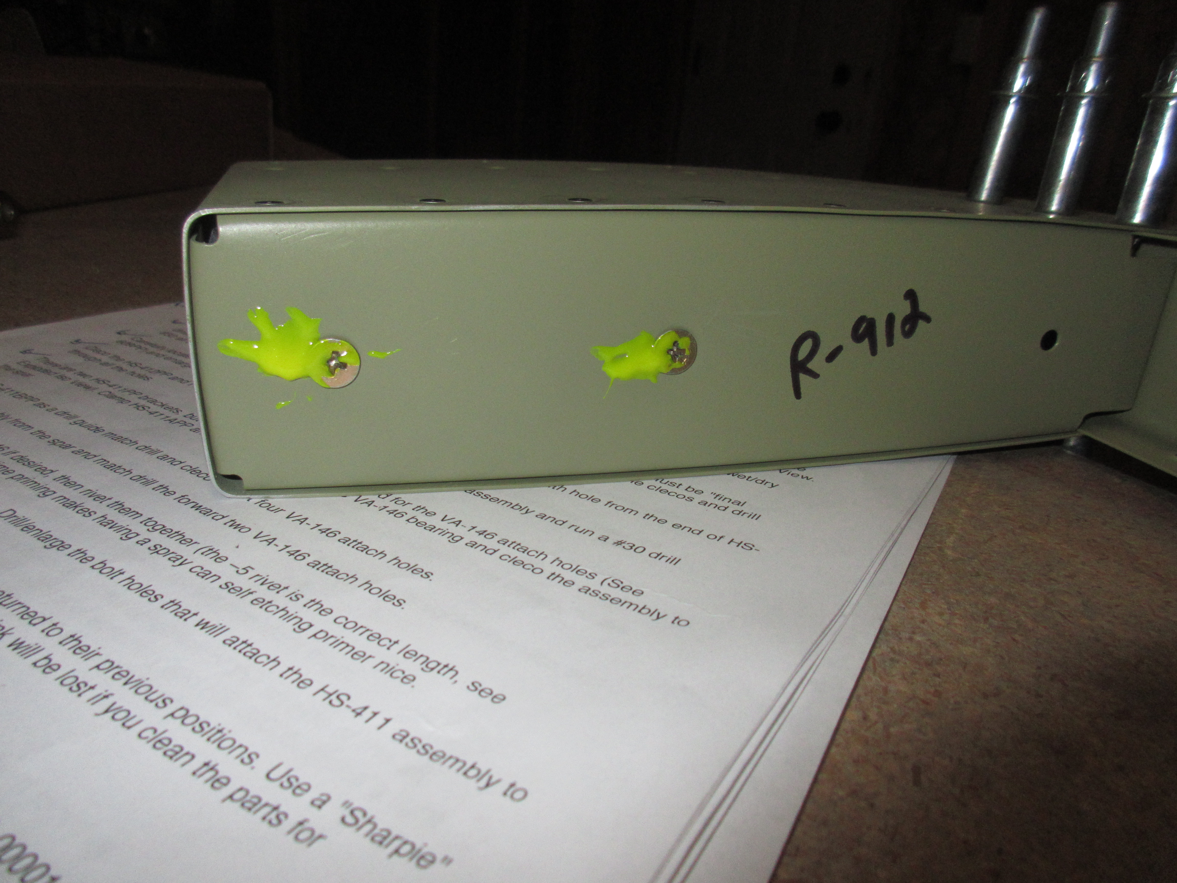
I then decided to skip back up to the doublers and platenuts on the E-702 spar.  These were fairly easy to do, I just double checked that I had the right length rivets in the right holes, as we use three different lengths in these sections.  I also double checked I had the orientation of the platenuts correct as well, and then used the squeezer to set al these rivets.  I love the way it came out!

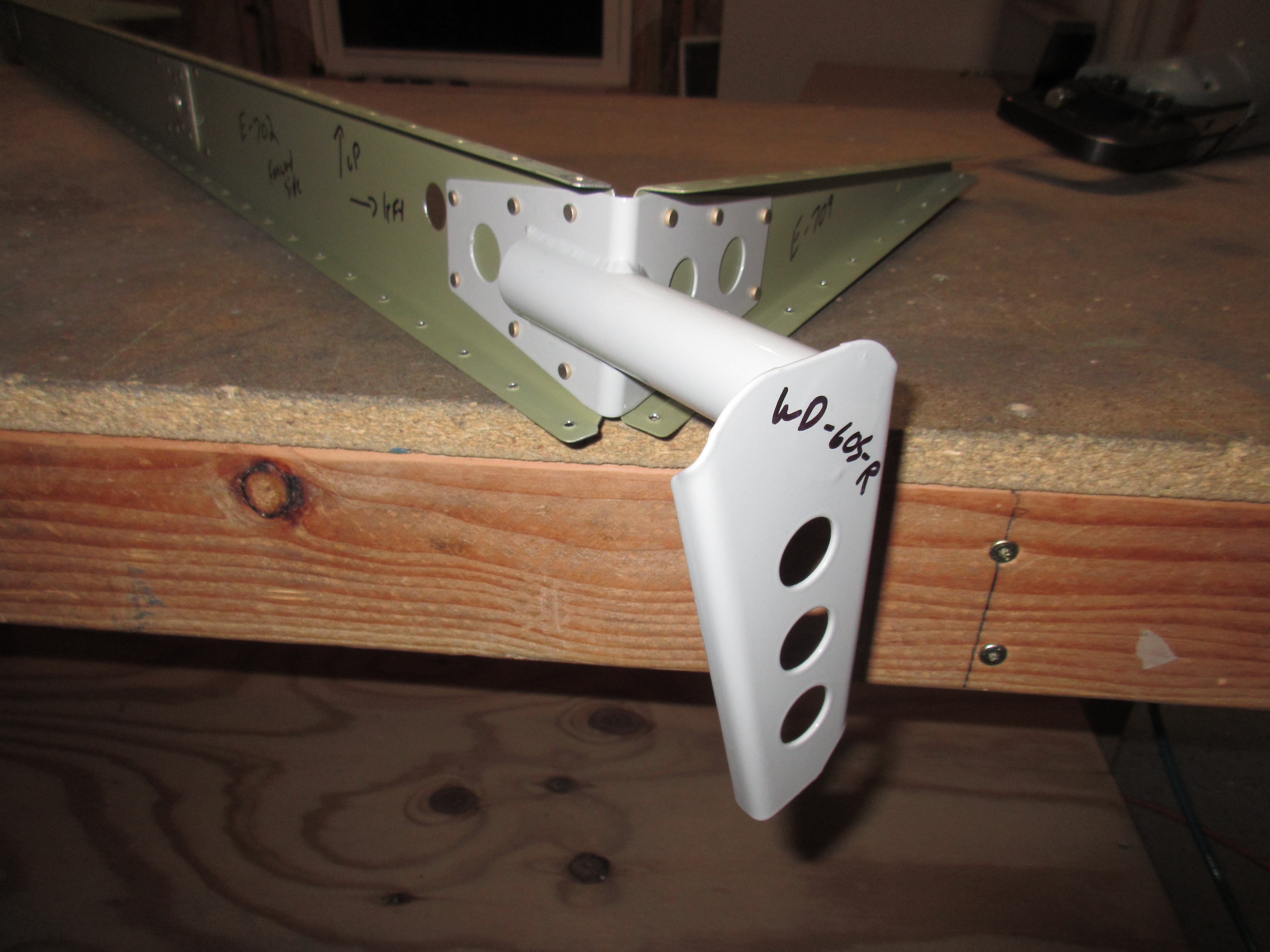
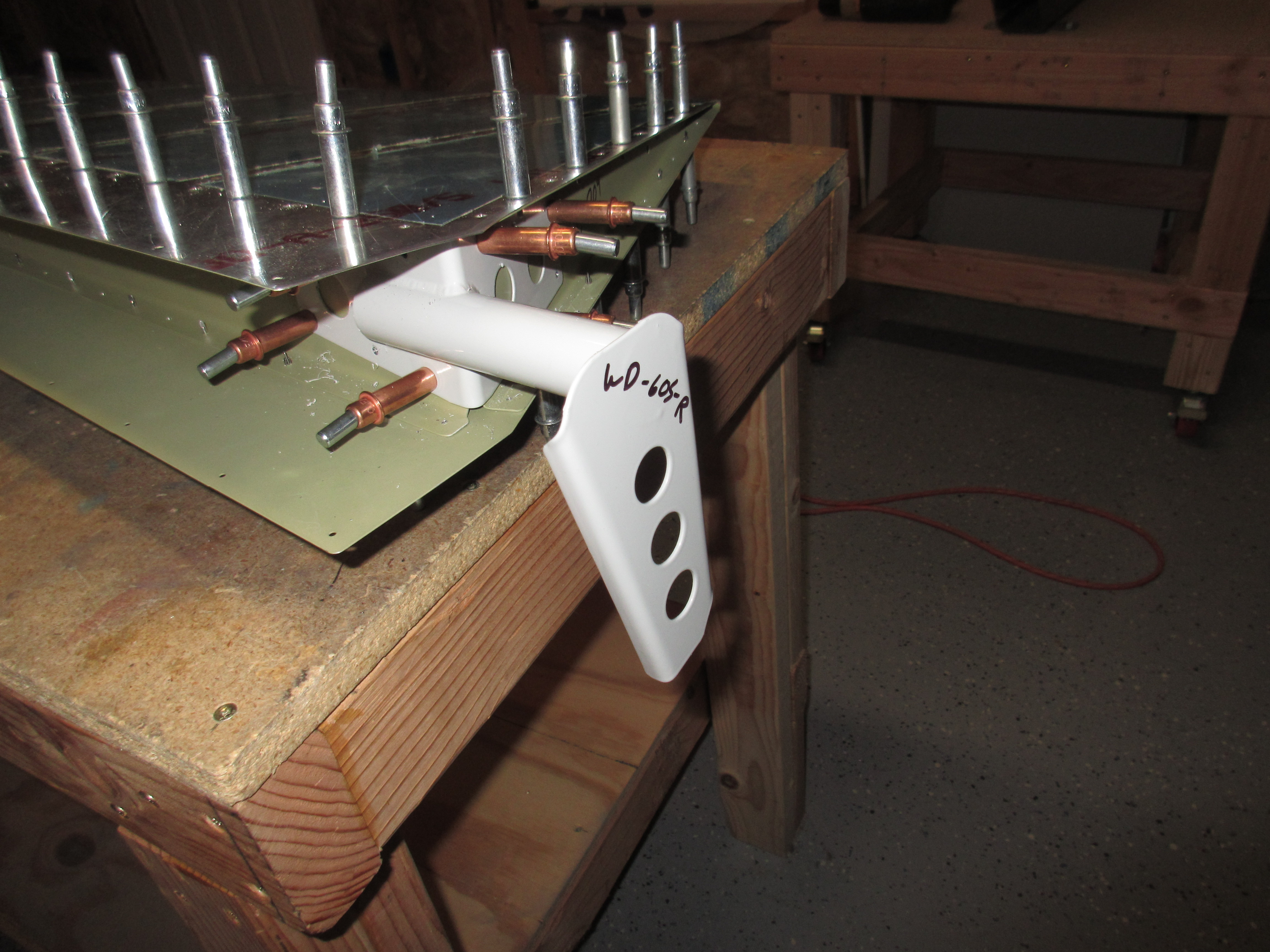
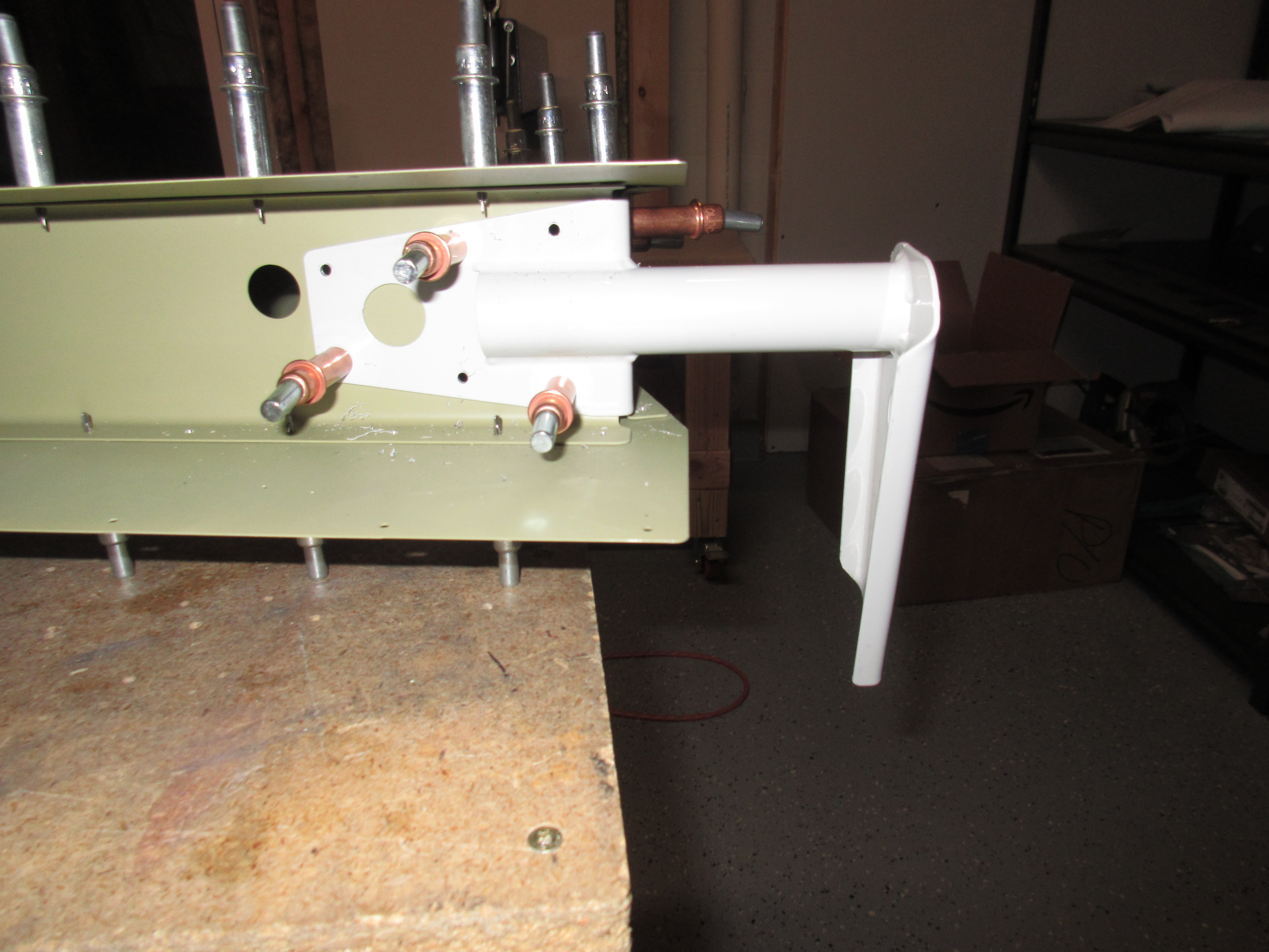
Finally, I decided to rivet on the WD-605-1-R elevator horn to finish off the skeleton.  Again, double checking the orientation, because it is possible to put this part on upside down if you’re not careful.  Then, I riveted in using AN470AD4-4 rivets and my squeezer.

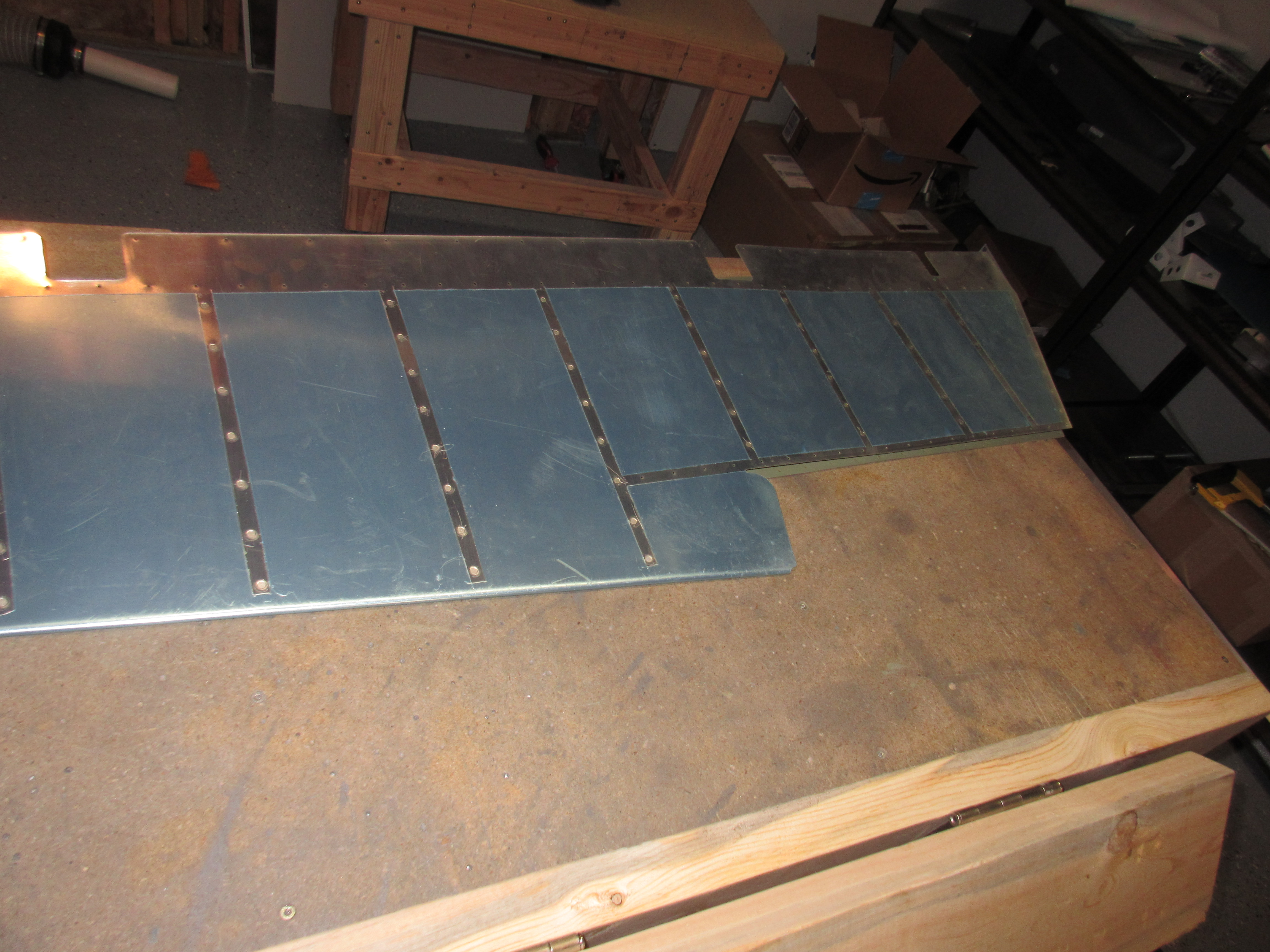
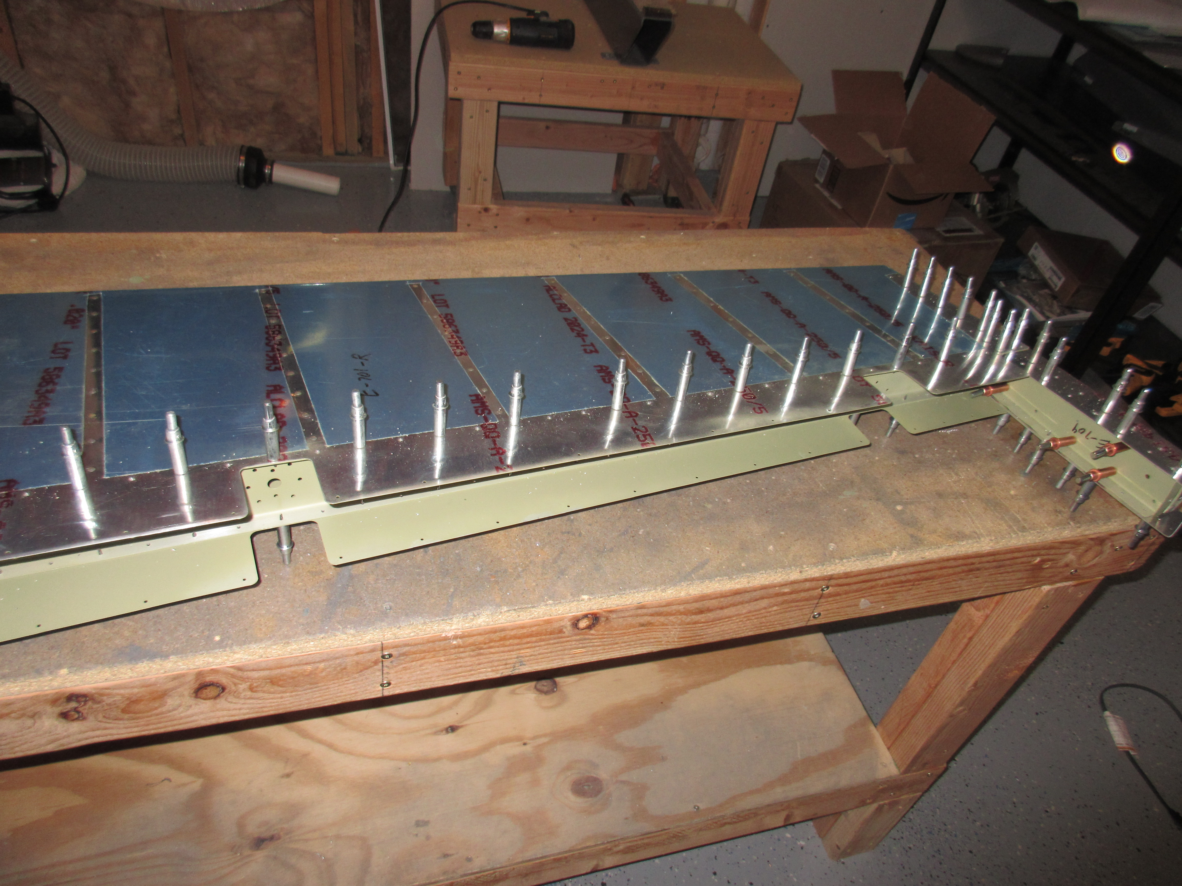
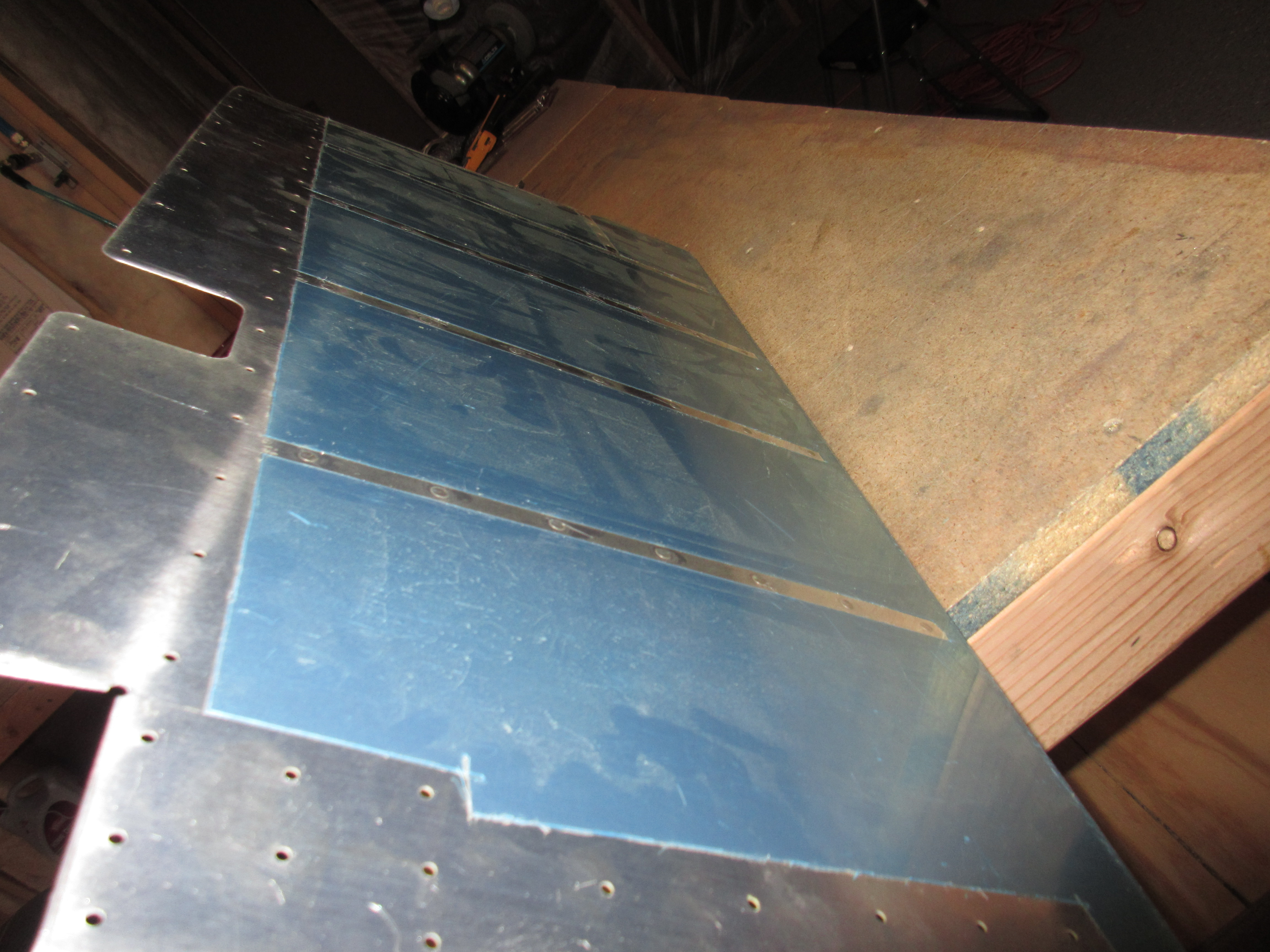
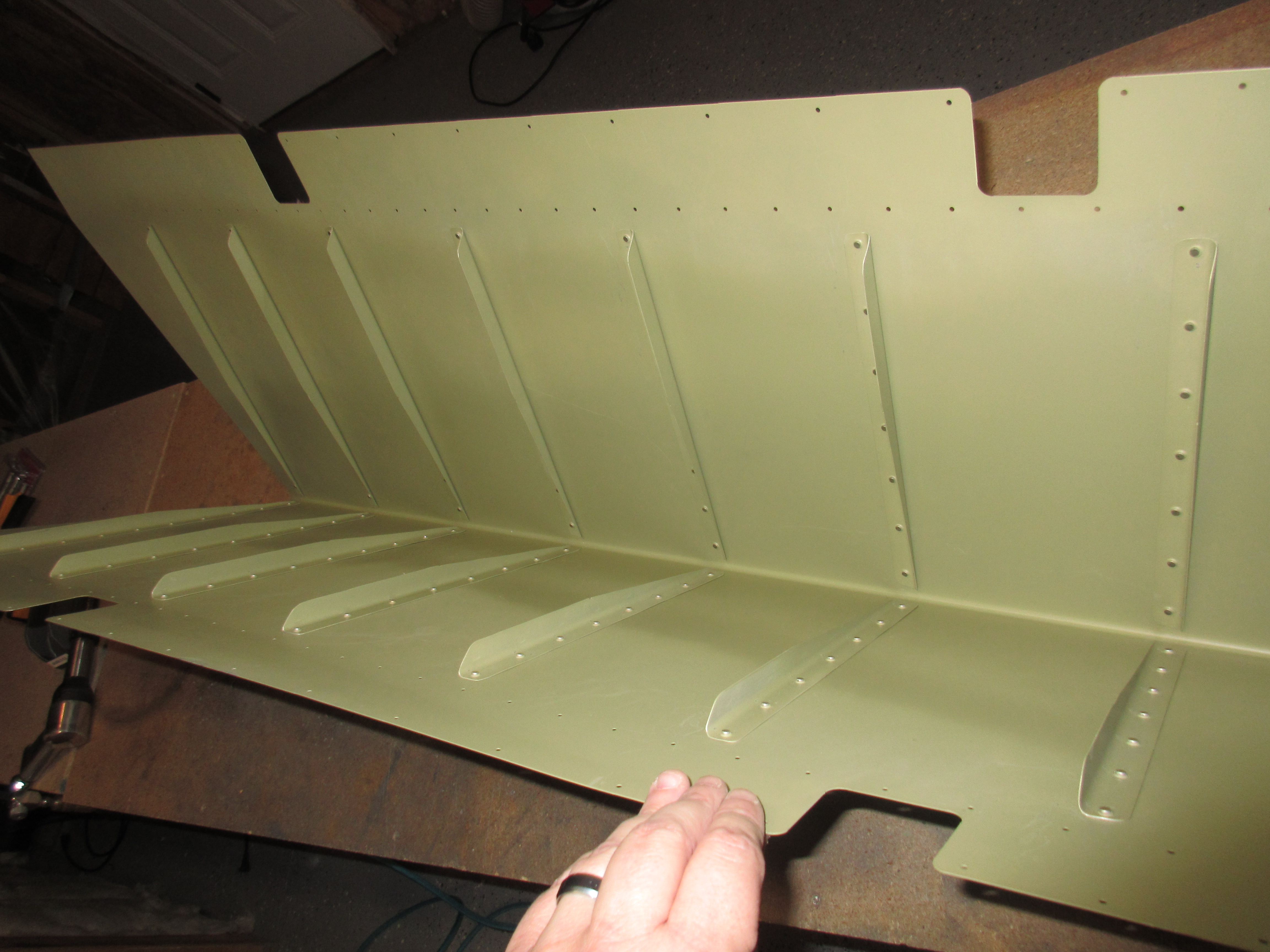
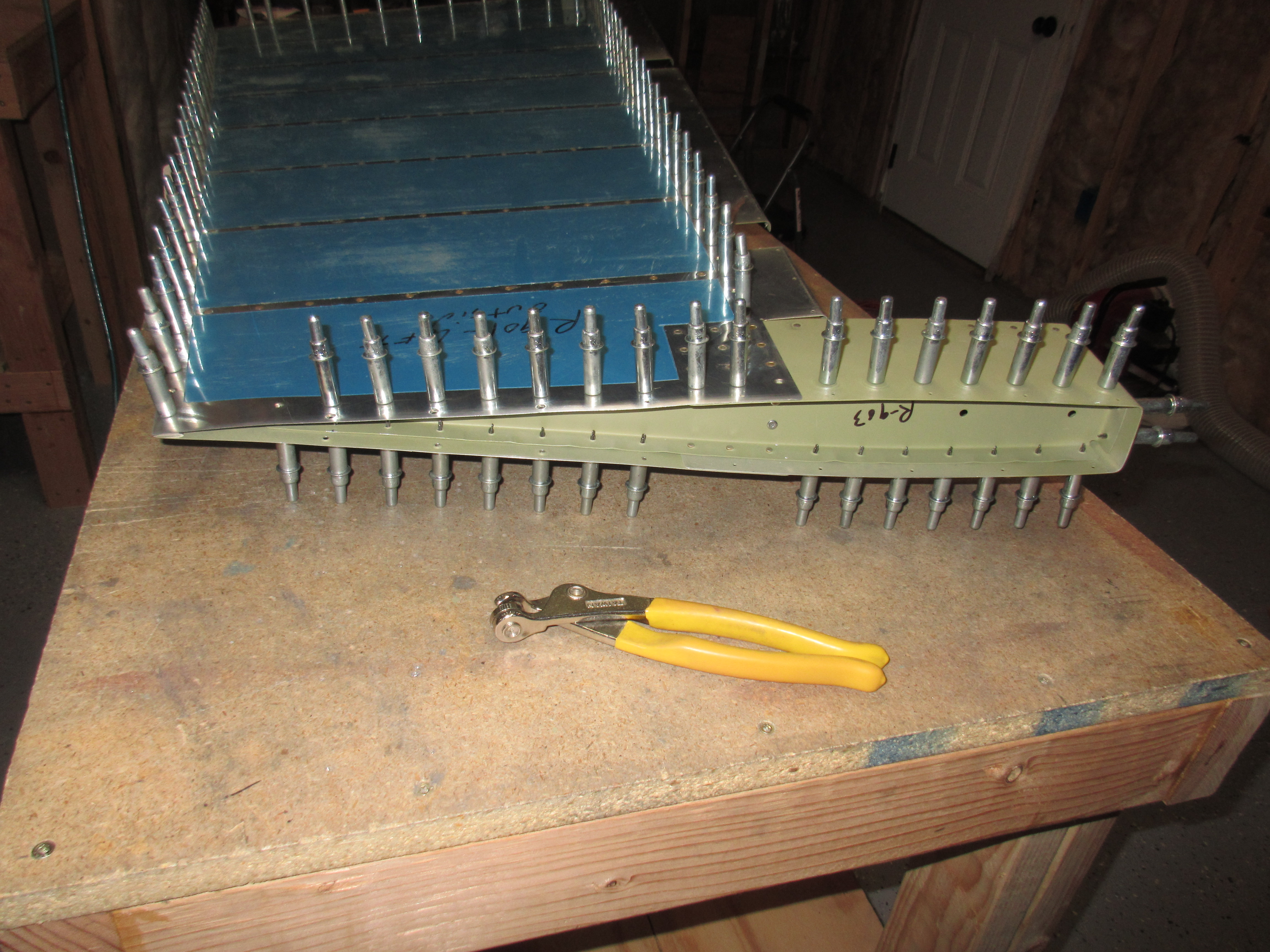
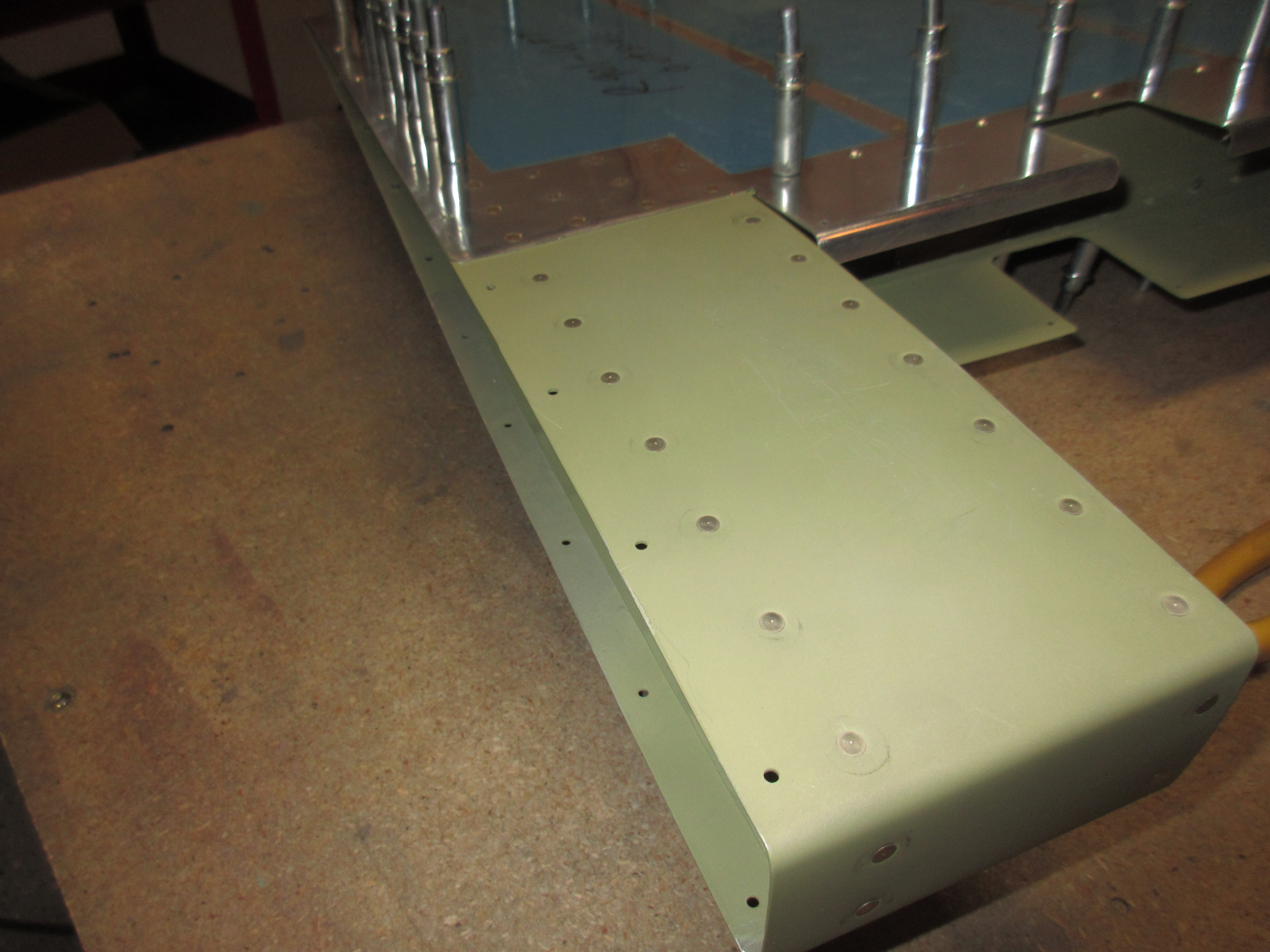
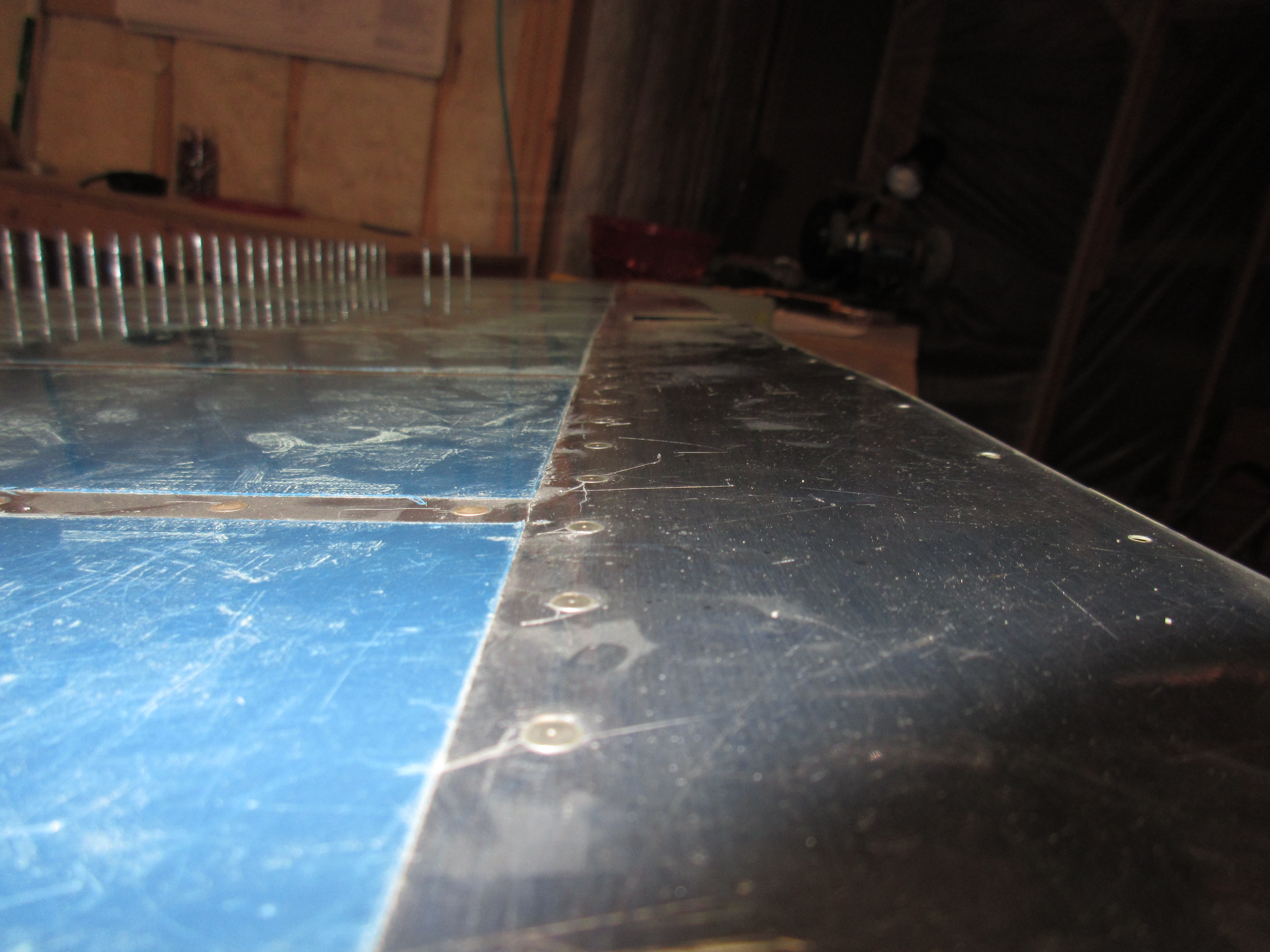
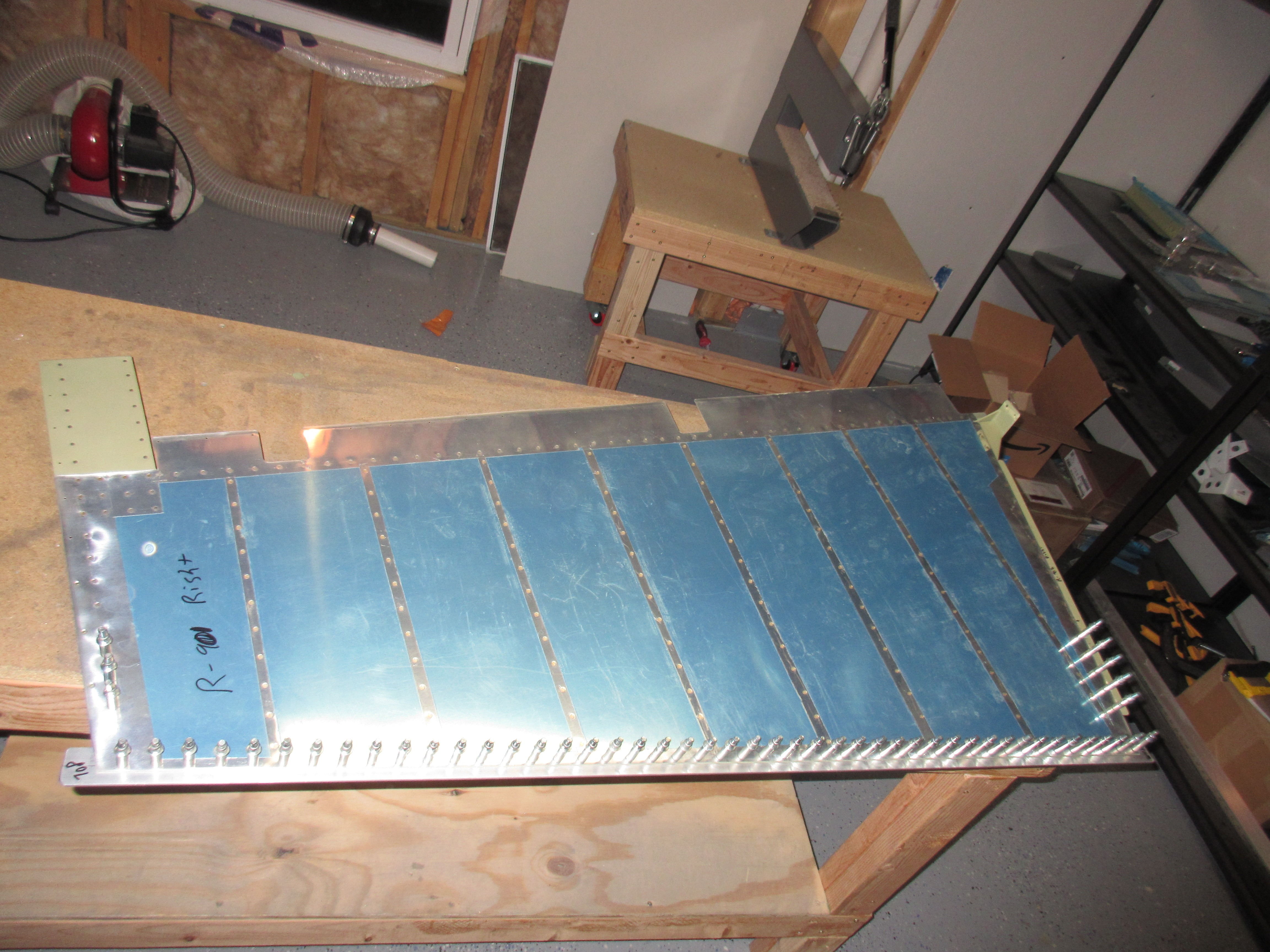
This finishes up the right elevator skeleton, and in the next session, I think I will rivet the skin to the elevator, but I am still debating on saving that portion until I get ready to pro-seal the rudder trailing edge.  This way I can use the same ProSeal to bond the trailing edges of the stiffeners of the elevators. We’ll see how it goes.  Here’s the photos from tonights session:

This slideshow requires JavaScript.

Google Photos Album link: https://goo.gl/photos/Mu4Tk4GGtpf46Rmq9

Hours Worked: 3


Priming a Few Parts For the Right Elevator

I started off tonight by priming a few little odds and ends for the right elevator. I had missed the little doublers in my first round somehow, and I needed to prime the replacement counter balance skin too. I decided to mix up a very small amount of AKZO and use my primer pistol to spray these few parts. The primer pistol is dead simple, and uses film cans as its paint cups which makes it easy cleanup.

This was the first time I have ever used this primer pistol, and its pretty convenient,  However, it sprays super heavy, so I had to back way away from the parts.  I did get a little bit of bubbling on one of the doublers from the heavy spray, but I’m not worried about it since its a part that will not be visible.  I followed my normal procedure of scuffing with scotchbrite, cleaning with acetone and priming.  I am pretty happy with the way these parts came out, regardless of the heavy spray from the primer pistol.  It done a decent enough job, and the next time, I will just keep the tip far away from the parts to get a thinner coat.  I do like how easy the cleanup is: Just toss the little film can and run a small amount of acetone down the tiny copper tube.

That was pretty much it for this small session.  After cleaning up, I took a short break and will come back down to finish up the skeleton in another session tonight. Spent about 45 minutes on this, counting the 30 minutes for the AKZO to catalyze after mixing it up.  I used that time to prep and clean the parts.  Heres all the photos:

This slideshow requires JavaScript.

Google Photos Album link:

Hours Worked: .75

Final Prep on Right Elevator

Its almost time to rivet the left elevator together, but first I have to take care of a few last tid bits. I disassembled the right elevator and deburred all of the parts, including the skin. The next step was to dimple the skin using the DRDT-2 and then dimple the skeleton parts using my squeezer, since some of these ribs have limited access.  On the trailing edge of the ribs, I had to break out the pop rivet dimple dies to get in those tight spaces, which takes a little time and patience.  The parts came out looking great and a test fit of a AN426 rivet seemed to agree:


Then I beveled the edges of the E-713 counter balance skin so that it would have an easy transition from the E-701 skin laying over the top of it. I started out getting it roughed out with a file, and then finished it off on the scotchbrite wheel to get a nice smooth bevel.  I also rolled the edges of the skin so that it will lay nice and flush against the E-713 when it comes time to rivet.  These little time sinks are things that take patience but are what creates a superb quality product in the end, so its time well spent.

Even though it doesn’t seem like a lot got done tonight, I had a solid 2.5 hours of work getting these parts prepped for final riveting.  Since I had to replace the E-713 counterbalance skin, I will need to do another small priming session to prime the inside of the skin, and I am going to also prime a few of the doublers for the nut plates as well.  I will probably setup for the priming session tomorrow and maybe start riveting the skeleton together.  Here are the photos from tonights session:

This slideshow requires JavaScript.

Google Photos Link: https://goo.gl/photos/D6SH5X6hfyLBFwYi8

Hours Worked: 2.5

Bending the Left Elevator Trailing Edge

I spent about 20 minutes bending the left elevator trailing edge in the bending brake tonight.  I figured since I already had my bending brake setup on my bench, I might as well go ahead and bend the left elevator as well.  Since this elevator doesn’t have as much trailing edge to bend (due to the trim tab), it was really easy to get bent to the right shape and only took about 20 minutes counting checking it with a straight edge. It came out great, and then went back on the shelf until I get ready for it.

I decided to do a little more work on the right elevator since it took less than a half hour to bend the left.  I thought I would go ahead and get the right elevator assembled so I could match drill the skin to the skeleton and get it ready for dimpling.  While I was assembling the E-713 counterbalance skin to the E-703 and E-704 ribs I realized I made my first mistake, and one so bad I would need to order some new parts 🙁  I made the mistake last month during the initial assembly  which you can see by this photo. Notice the counterbalance skin, I have it flipped over in the wrong direction.  This cascaded down to when I drilled the lead counterweight.  So, essentially what happened is I assembled everything with that skin flipped over, and then match drilled the counterweight to it.  Tonight, when I started assembling everything together, I noticed the counterweight holes were not lining up, which is when I noticed that I messed this part up.  You can see from these photos how the parts were drilled:

That counterweight should be on the OTHER side of the rib and you can see the sharpie marks I made tonight to see just how bad it would be to re-drill.  These holes are too close so re-drilling them is not an option.  But, it looks like only the counterweight and its skin are needing to be replaced, and since the kit came with two (one for the left and another for the right) I can just use the remaining  E-714 and E-713 that would have went on the left side,  to keep working until the replacement parts come in. Both the left and right parts identical.

Thank goodness that I only need to replace two parts, the E-714 counterweight and the E-713 counterbalance skin for a grand total of about $40 from Vans.  I am so glad I caught this now, before I wound up having to replace more parts!  Oh well, I guess its good that my first mistake was something that is easy to fix and cheap to replace.  Luckily it won’t hold up any progress while I wait on the new parts.

So, I pulled out the E-714 and E-713 from my stock and re-drilled the skin and counterweight MAKING SURE the orientation was correct this time :-).  Drilling lead is a pretty rough task on a drill bit, so I kept it slathered up in Boelube.  With that squared away, I decided I’d go ahead and assembly it to the skeleton and then match drill the left elevator skin to the skeleton to get it ready for dimpling.  This was pretty uneventful, and went quickly.

Lasty, I figured I would get the last little step done tonight which was to match drill the WD-605-R elevator horn to the inboard side of the rudder.  I cleco’ed it on to the inboard R-709 rib, double-checking its orientation (I bet this part is expensive to fix, compared to the counterweight ha!), and then drilled it with a #40 drill bit.

And with that, the right elevator is ready for disassembly, dimpling and then riveting. That will be in another work session, I was a bit frazzled after worrying about messing up the counterweight, so I called it a night.  Here is the album for all the photos:

This slideshow requires JavaScript.

Google Photos Link: https://goo.gl/photos/2i6PtVKFbjNHSrat8

Hours Worked: 2.5

Riveting the Left Elevator Stiffeners

More Stiffeners!! Tonight I think I should be done with stiffeners at least for a little while (wing kit maybe?).  I worked to rivet the last remaining stiffeners on the left elevator, and then moved on to attaching the E-615PP trim support plate.  First, I started off by working on dimpling and countersinking the E-615PP support plate to get it ready to rivet on the nut plates.  I found my #6 dimple die and I have decided to use NAS1097 3-3.5 rivets to hold the nut plates on.  I used my deburring bit and machine countersunk the E-615PP by hand.  This took a little time, but it guarantees a very nice finish.  I test fit each rivet in the holes to make sure they were nice and flush.

Then I dimpled the screw hole with a #6 dimple die to fit the dimple in the trim cover plate and its screw.  Once I had all the holes countersunk and dimpled, I began back riveting the nut plates onto the plate.  I decided to back rivet because this leaves a very nicely finished rivet and doesn’t take any extra work. I am really happy with how the nut plates turned out:

With the E-615PP completed, I moved on to the last of the stiffeners!  There isn’t much to talk about here, since I have done this several times in the past, and the process is the same.  I back rivet the stiffeners onto the skins and make sure everything is flush and straight.  The only difference is that this time, we are also going to back rivet the E-615PP support plate to the skin as well.  It serves as both a stiffener for the inboard end, as well as a doubler for the electric trim servo and its mounting plate.  I took my time, and everything came out looking really nicely.

This was about 2 hours of work, but I decided to take a break and then start working on my bending brake for the trailing edge of the elevators, and maybe bend one up.  Thats all for this session, here are all the photos from the build:

This slideshow requires JavaScript.

Google Photos Link: https://goo.gl/photos/JTmj5mFvK3qrvBbr8

Hours Worked: 2

Bending the Right Elevator Trailing Edge

I built my bending brake / jig for the trailing edge of the elevators tonight, and decided to give it a whirl on the right elevator.  It came out really good, and it looks like the trailing edge is going to be straight as an arrow.  I had been working on the plane earlier today, but took a short little break and started back at it.  First up, I had to build my bending brake / jig using some 2×6 boards that I picked up a couple of weeks ago from the Lowes Aviation Suppy here in town.  Van’s has some directions on how to build a simple little brake, but I have modified it very slightly per some suggestions from Vans Air Force members.  Instead of hinging the 2×6 boards so they fold width wise, I hinged them so they fold on their narrow side, which should make the break much more sturdy.

This lets me clamp the brake to my work bench so I can use it easier, and gives a nice flat surface for the elevator to lay against during bending. It also lets me use more leverage.  Bending the trailing edge took a bit more work than what I was thinking.  It takes quite a bit of force to get this thing to lay down! I did my bending in short easy bends so I didn’t over do it, checking as I went to make sure the elevator is bending straight.  After several rounds of applying pressure, removing the elevator and checking it, I finally started to get it close to being bent.

Once I get the skin to the point that it laid naturally across the front spar, I clecoed the front spar and the end ribs in place to get a better idea of how it was turning out.  I was pretty close at first, but had to put it back in the brake a few more times to get it perfect. I used my square to check that the bends were complete.  What we want to see is the skin flat against a straight edge, all the way from the front spar, down to the trailing edge, where the bend sharply drops off to a perpendicular to the square.  If the skin sort of “falls” slowly away from the straight edge, you haven’t bent it enough.  If the skin concave’s away from your straight edge, you have to much bend.  Too little bend is WAY easier to fix than too much, so I did this in small steps to make sure I didn’t over do it. I checked the skin from the top to the bottom at every stiffener and in between the stiffeners using my square and its looking really great:

However, I think I have a very slight twist in the elevator somehow.  When I laid a straight edge (4 foot aluminum drywall ruler) across the trailing edge from top to bottom I noticed that the trailing edge bowed about 3/32″ around the middle.  I thought I had a photo of that, but it was overexposed from the flash reflecting off the ruler.  But, I decided to call it a night at this point.  I am fairly happy with the trailing edge, and I’m going to post a question over on the forums about the very slight bow.  It’s probably easily fixable seeing as how I haven’t riveted the elevator yet. Heck, the 3/32″ may actually be in spec for the rudder, I’m going to do some research and find out.  Here’s all the photos from this build session:

This slideshow requires JavaScript.

Google Photos Link: https://goo.gl/photos/NrH78YdKxtHENdNV6

Hours Worked: 1.75

Riveting the Elevator Stiffeners

Stiffeners.  I swear this plane has more stiffeners in it than skin. Since I am holding off on bonding the trailing edge of the rudder for a few more days, I decided to move on to the elevators and start riveting the stiffeners on.  This will help get me to the point of bending their trailing edge and bonding the trailing edge stiffeners, which is what I am waiting on for the rudder.  This way I can mix up one batch of ProSeal and do them at the same time.  I already have my skins and stiffeners primed and ready, I just need to deburr and dimple them before riveting.

Thats where tonights work started.  I deburred the stiffener holes in the both the E-701 left and right skins.  Then I fired up the DRDT-2 dimpler and dimpled both skins, as well as all the stiffeners for both sides.  This went pretty quickly, since they were all AN4263-3.5 rivets. The dimples always turn out nice:

Next up was to back rivet all of the stiffeners to the skins, so i started on the right being that its the easiest.  Back riveting is one of my favorite ways to rivet, and I’d gamble probably most of the other builders out there as well! The rivets set so nice and perfect, and its pretty easy to do so long as you keep an eye on where your back rivet plate is.  I picked up a longer 16″ plate to have more room to work and its been awesome.  Here’s some quick shots of the end result on the right skin.

After I had the right skin all completed, I put it on the shelf and started on the left.  The left is slightly more complicated because it has the elevator trim system, so we have a few more pieces to work with.  I started out by marking where the E-615PP support plate went on the inside of the skin, and then deburred and dimple those holes on the skin and the plate.  This plate will get some nut plates around the inside opening, so I need to dimple the nut plate mounting holes and screw hole.  Here’s where I had a head-scratcher.  I have in my dimple die collection a 5/32 and a #6 dimple die….The plans call for a #6 screw to be used with the nut plate, so that means I need to use a #6 dimple die, but I cannot figure out which is the 5/32 and which is the #6!!! The markings are no longer on the side of my dies and they are VERY close in size.  I also took some time fitting the plate and pondering if I should dimple the AN4263-3.5 holes that the plans calls for, or if I should use some NAS1097 rivets and countersink them.  If I dimple, I will have to fiddle with dimple the nutplate ears, and that gets messy.  I am thinking about using some NAS1097, AKA “oops rivets”, instead.  They have a smaller countersink on the head, but since these are just holding the nut plate in place there isn’t much load on them.  Using NAS1097’s will let me machine countersink the plate and get a very close fitting rivet set and not have to worry about the nut plate ears.  I figured I would just call it a night here, and put some thought to this overnight and ask some folks on the Vans Airforce forums.  Maybe they can help me sort out which is a 5/32 and which is a #6 die as well! 🙂  Here’s the work I did get done one the E-615PP:

In the next session, I will back rivet on the stiffeners to the left skin, and figure out this E-615PP support plate conundrum, and probably make up the trailing edge bending jig.  Here’s the photos from tonights work:

This slideshow requires JavaScript.

And heres the Google Photos link: https://goo.gl/photos/ZMa9huaebXyCxRGS7

Hours Worked: 3.25

Riveting the Rudder

Tonight I started riveting the rudder together.  I planned on getting the majority of the rudder riveted, while leaving the out the last few rivets along the trailing edge.  This way I can more easily spread the trailing edge to make it easier to bond the trailing edge wedge and rivet it.  I spent about three hours on the rudder tonight, and it came out really great so far!

The work started by rolling the edges of the skins where it laps over the counterbalance skin.  I used my edge rolling tool to accomplish this, and it formed a nice little break that will let the two lap joints fit nicely with no lipping.  I also rolled the edges of the leading edge skin so that it will lap together very nice when I finally finish up the leading edge.  After that, I studied the plans, as there are several spots on the rudder that require different sizes, and made sure I had the proper locations identified.

I started riveting at the overlap of the R-901 skin and R-913 counterbalance skin.  These rivets have to be set first, because they become inaccessible once we install the R-903 tip rib. Once I had these rivets set on both sides, I installed the R-903 tip rib and clecoed every hole because this is a rather compound and complex curve. I started riveting by pop-riveting the rib to the R-902 spar per the plans.  Then I used the AN426 flush rivets on the very leading edge, where the tip rib fits into the counterbalance skin and began working my way toward the tip, removing one cleco at a time and then riveting in that hole.  Flipped the rudder over and done the opposite side.

On the upper side of the rudder, I left the last 6 or so rivets out of the tip rib/skin so that I can flex it open to install the trailing edge.  Once I had the upper tip riveted up, I decided to continue on and rivet the skin to the spar on both sides and then rivet the bottom rib.  I started out by riveting the skin to the rear spar in every other hole that way the clecos would hold the skin flush to the spar nicely.  Once I had every other hole riveted, I removed the remaining clecos and riveted those holes.  This worked really well, as I could insert all the rivets, and squeeze them in “batches” instead of one by one.  Once I had a side completed, I flipped the rudder over and riveted the opposite in the same manner. It turned out looking very nicely, but pardon the dust 🙂


All that was left as this point was the bottom rib,  the R-710 rudder horn brace and fiberglass mounting strips.  I started out by swapping out the nose on my squeezer so that I could fit into the tight space of the rudder horn in order to set those rivets.  I had BARELY enough clearance to get them done, but it worked out after being very careful with the squeezer.

Now that the hard part was riveted on, I continued on down the bottom of the skin and squeezed the rivets along the R-904 bottom rib, R-918 attach strips and the R-901 skin.  All of the rivets on the rudder I was able to set using my squeezer, so the results came out very clean and neat.  I did leave the last few rivets along the bottom rib out so that I can spread the skins to bond the trailing edge wedge.  I will set them while the trailing edge is bonding, so that will be in the next few coming weeks.  Here is what the rudder looks like after tonights session:

All in all, I am very happy with the way the rudder has turned out so far.  All the rivets are clean and flush, there is no warping or twist in the rudder that I can see, and I am ready to go for the trailing edge bonding.  That’s exactly what I had hoped to accomplish for this session, so I decided to wrap it up by clecoing on the my aluminum angle to the trailing edge and installing the edge wedge.  This way my rudder will be held perfectly straight while its sitting on the shelf waiting on the Proseal bonding, which I hope to do in the next couple weeks.   Here are the photos from tonights work:

This slideshow requires JavaScript.

Google Photos link: https://goo.gl/photos/zmNYk13To4x1Ju6c8

Hours Worked: 3

Rudder Final Assembly Continued

Tonight I continued working on the rudder final assembly.  I stopped by Home Depot and picked up some 1.5″ aluminum angle so that I could use it when I bond the trailing edge. It came in an 8 foot length, so I trimmed to be just a few inches longer than the trailing edge, finished out the rough edge on that cut and then marked the center of one side of the angle to help align my drill holes. I laid one of the rudder skins on flat against the angle and the lined up the mark I made with the pre-drilled holes in the skin.  Then I match drilled a hole to start and clecoed the skin and angle right into my work table.  Then, to keep from over-drilling the skin, I just drilled every two holes all the way through and clecoed.  For the remaining holes, I simply ran the bit for a few seconds to start a hole using the clecoed skin as a guide, and then pulled the skin off and finished drilling the holes through the angle.  I then laid the skin back over my holes and clecoed it in a few spots to make sure it was still lining up, and it was.

Then I set the angle aside and kept on working on the rudder itself.  I decided to fit the bottom R-710 rudder horn brace to make sure I could rivet everything in place with the brace installed, and luckily my squeezer will fit in the tight space of the horn brace and set the rivets easily.  I decided to use the AN470 rivets instead of the blind rivets that is optional for this part.  I used my squeezer to set the rivets and left the ones that the skin rivets too for later.  You can see in the photo below that the access hole in the R-710 horn brace gives just enough clearance for the squeezer to get in and set the rivets along the bottom rib.

After that, I decided to get the trailing edge ready for assembly before I cleco on the skins.  First I used the DRDT-2 to dimple the trailing edge of the skins, and the I used a new jig from Cleaveland Tools that makes countersinking the trailing edge wedge a breeze!  This thing is dead simple, its shaped to fit the angle of the trailing edge wedge, so that the working surface sits flush and allows all of the countersink cage to sit flush while countersinking.  This is something a lot of builders have a hard time with, and struggle to make a good jig, so Cleaveland made one from a solid piece of billet.  Here’s how it looks:

You can see how the trailing edge wedge sits perfectly in the groove, and the holes in the jig allow the nib on the countersink cutter to travel completely through.  This little $36 tool made this job so simple I was glad to have it.  I had both sides of my wedge done in about 30 minutes, counting the time I took to adjust the depth.


With the trailing edge wedge done, I was ready to cleco on the skins and make sure everything still aligned right before riveting them on.  I clecoed on both sides and then inserted the trailing edge wedge and clecoed it together.  My rudder is still in alignment and its looking great.  However, while I was sitting down admiring my work, I started questioning when I should insert the rod end bearings for the rudder mounts.  They thread into the plate nuts I installed into the spar, but the plans has some specific lengths they need to be, and it looks like its measured from the inside of the spar to the center of the hole in the rod end bearing.   Heres what I am talking about:

Of course, with the skins on, I wont be able to measure from the inside of the spar, and it looks like its calling for a distance of 51/64 in this particular instance.  So, I am going to ask in the forums if I should go ahead and install those rod end bearings before I rivet on the skins.  So, with that little dilema, I decided to call it a night and wait until I get some advice on how to proceed before I make it harder on myself down the road.  This is a good stopping point anyways!

Here’s an album of all the photos from tonights work:

This slideshow requires JavaScript.

Google Photos album link: https://goo.gl/photos/aHYpcitVP9jL4eYBA

Hours Worked: 3.75

Final Assembly of the Rudder

Well, I had some downtime, and didn’t get much done on the plane since I sprayed the primer.  I wanted to let the parts sit and the primer cure for a few days, but I wasn’t planning on this long 🙂  None the less, I got back on the ball today, and got some work done.  I want to finish up the rudder to the point of riveting the trailing edge, and then I will hold off on the Proseal until I need it for the elevator stiffeners as well.  So, lets build a rudder skeleton!

The work started off by gathering up and marking all the parts for the rudder.  Some of the marks were covered up with the primer, so I needed to find all the parts again.  I also took a little time to read the plans and get re-familiar with the rudder.  I had already deburred the parts before priming, so I needed to dimple the skins, spar and ribs. This went pretty quick with the DRDT-2, and using the pop-rivet dimple die tool to get the very end of the ribs.  I am still not sure how the heck I am going to rivet those things.

With all the parts deburred, dimpled, primed and ready to assemble, I began the work of final assembly on the rudder skeleton.  We start out  by riveting all of the reinforcement plates, R606PP, R607PP, and R608PP to the rudder spar R902. I also riveted on the K1000-6 nut plates to the proper sides of the rear spar.  I decided to leave these unpainted, since they have corrosion protection already applied.

Once the reinforcement plates are riveted on, I moved towards the bottom of the rudder and worked on the lower rib and rudder horn.  The R-904 has several different pieces that all fit together on the spar to form the lower assembly.  I attached the R-904 to the R-902 rear spar, fitted the R-917 shim, and finally fitted the R-405PD rudder horn with clecos.  Then I attached the K1000-6 plate nut to the assembly and riveted everything together.  There are several different lengths of rivets in this section, so I had to pay close attention and double check each rivet before setting it.

Now that the bottom of the skelton was done, I moved on to finish the top. Vans has us rivet the R-912 counterbalance rib to the rear spar, and then fit the R-913 counterbalance skin over the rib.  I attached the skin with clecos due to its thickness and the complex curve it has.  Then once I was happy the counterbalance skin was fitted nicely, I removed one cleco at a time and riveted it in place. It came out looking great!

The last step on this skeleton was to install the lead counterbalance weight.  I had pre-drilled and countersunk it a few weeks ago, but I still needed to do a little trimming to get the counterweight to fit around the rivet tails that were now sticking inside the skeleton.  I didn’t have to remove much material, so the balance shouldn’t be affected.  Then I secured the weight with the AN509 screws and torqued them down to 30 inch/lbs.  This is the 25 inch/lbs that is called for, plus the drag of the nylon lock nut, which I measured at about 5 inch/lbs.  I followed that up with a little torque seal to mark that I had them torqued, and also to show in case the screws start to work loose.

I called it a night at this point. I have a full rudder skeleton, and the next step is to cleco on the skins and start getting them ready to rivet, and then place the end rib on the top.  In the next session, I will cleco on the skins and make sure every thing is still lined up, and then use one of the skins as a guide to drill some aluminum angle for the trailing edge.

Heres all the photos from tonights work:

This slideshow requires JavaScript.

And the Google Photos link: https://goo.gl/photos/SRSXVZCsuYNEQqeY6

Hours Worked: 4.5