


Well, I had some downtime, and didn’t get much done on the plane since I sprayed the primer. I wanted to let the parts sit and the primer cure for a few days, but I wasn’t planning on this long 🙂 None the less, I got back on the ball today, and got some work done. I want to finish up the rudder to the point of riveting the trailing edge, and then I will hold off on the Proseal until I need it for the elevator stiffeners as well. So, lets build a rudder skeleton!
The work started off by gathering up and marking all the parts for the rudder. Some of the marks were covered up with the primer, so I needed to find all the parts again. I also took a little time to read the plans and get re-familiar with the rudder. I had already deburred the parts before priming, so I needed to dimple the skins, spar and ribs. This went pretty quick with the DRDT-2, and using the pop-rivet dimple die tool to get the very end of the ribs. I am still not sure how the heck I am going to rivet those things.
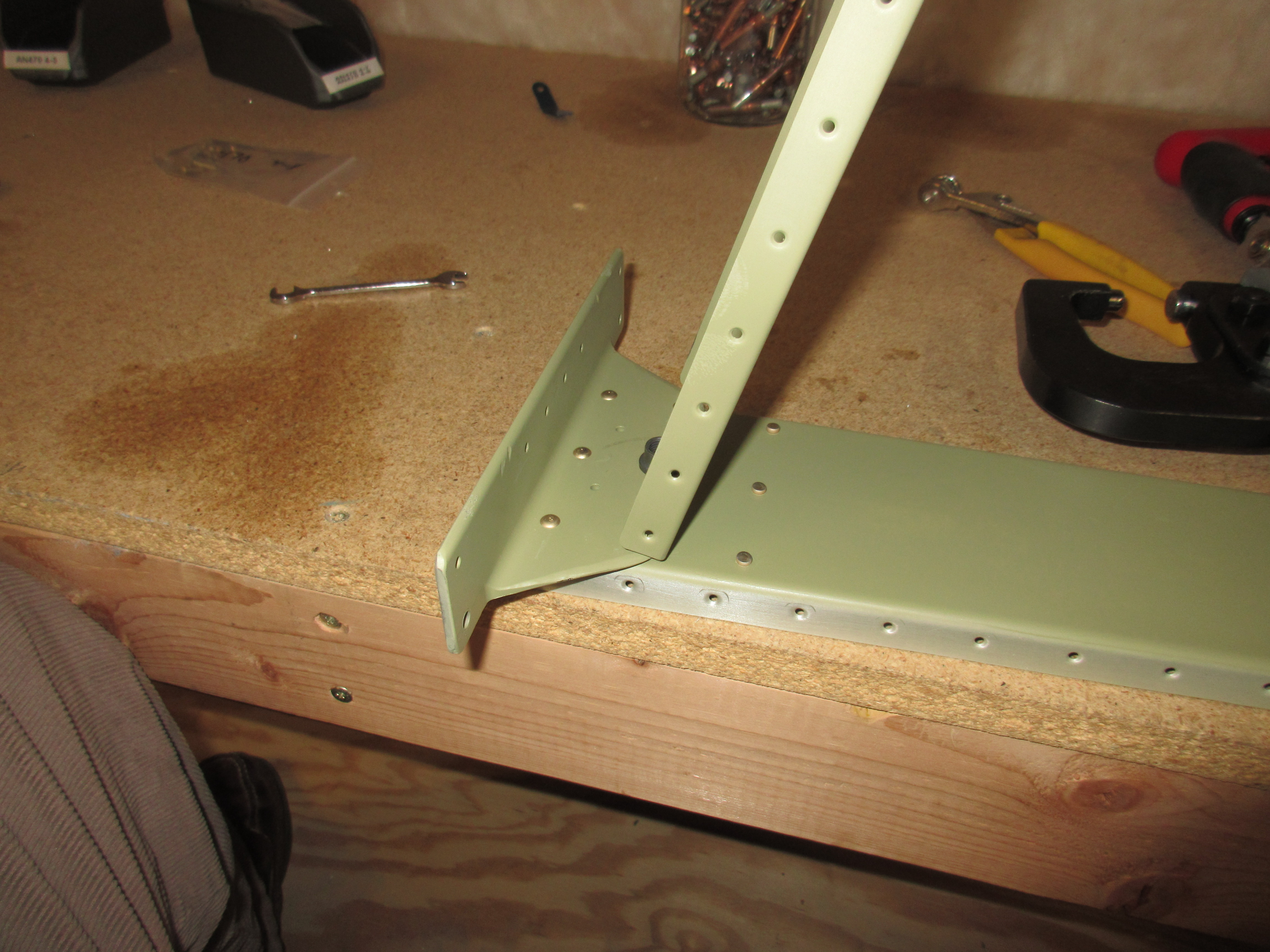
With all the parts deburred, dimpled, primed and ready to assemble, I began the work of final assembly on the rudder skeleton. We start out by riveting all of the reinforcement plates, R606PP, R607PP, and R608PP to the rudder spar R902. I also riveted on the K1000-6 nut plates to the proper sides of the rear spar. I decided to leave these unpainted, since they have corrosion protection already applied.


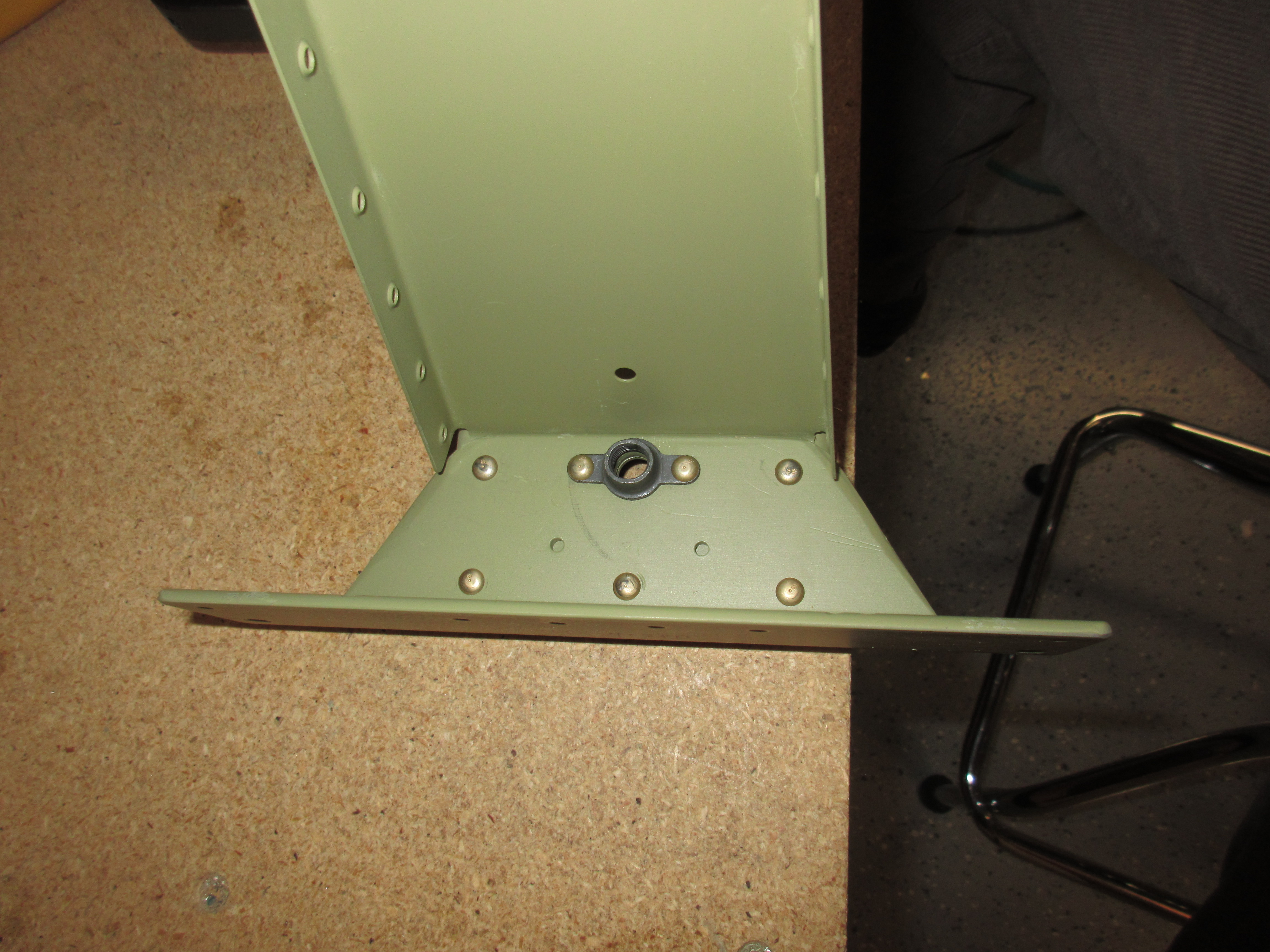
Once the reinforcement plates are riveted on, I moved towards the bottom of the rudder and worked on the lower rib and rudder horn. The R-904 has several different pieces that all fit together on the spar to form the lower assembly. I attached the R-904 to the R-902 rear spar, fitted the R-917 shim, and finally fitted the R-405PD rudder horn with clecos. Then I attached the K1000-6 plate nut to the assembly and riveted everything together. There are several different lengths of rivets in this section, so I had to pay close attention and double check each rivet before setting it.
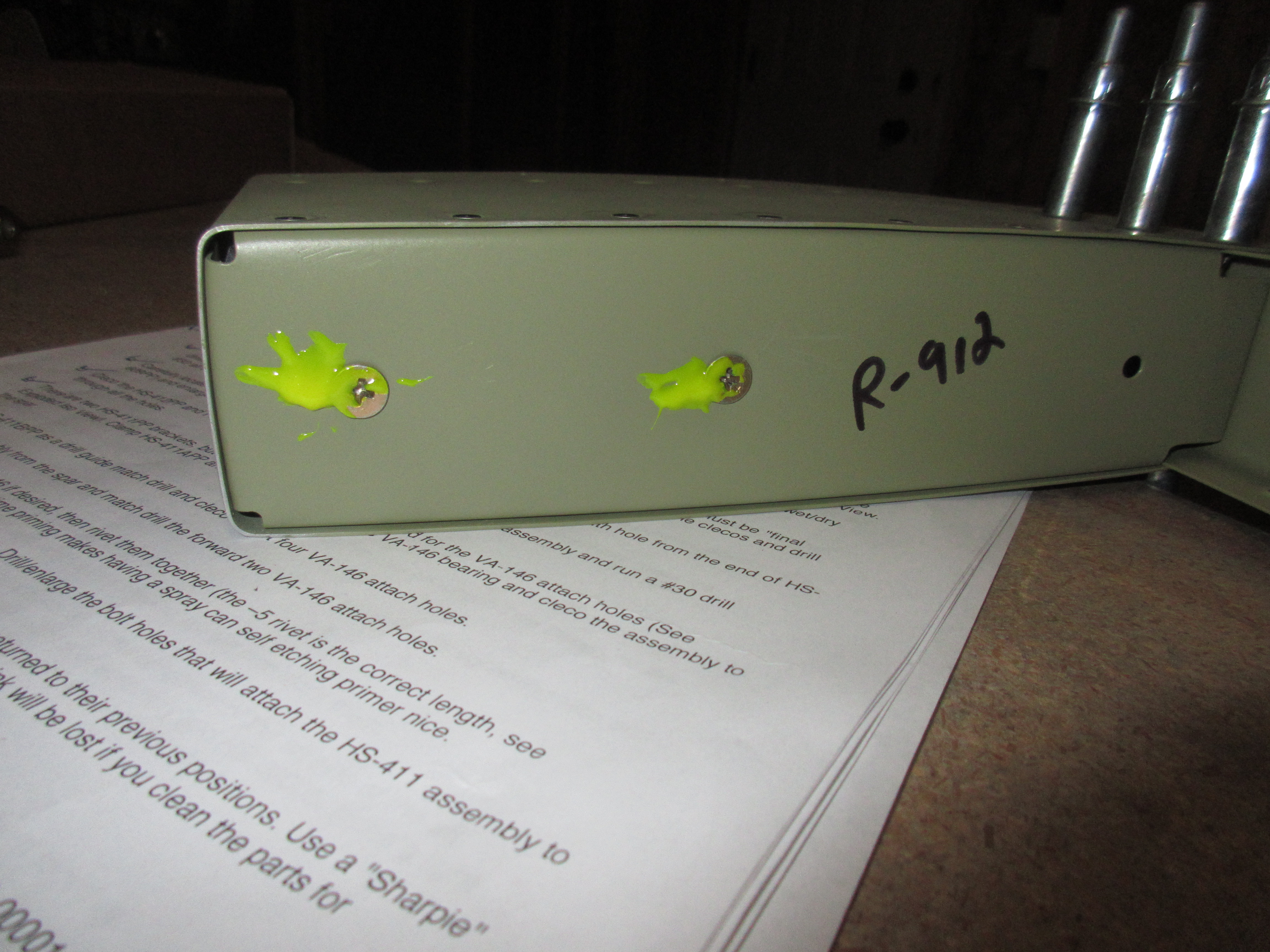
Now that the bottom of the skelton was done, I moved on to finish the top. Vans has us rivet the R-912 counterbalance rib to the rear spar, and then fit the R-913 counterbalance skin over the rib. I attached the skin with clecos due to its thickness and the complex curve it has. Then once I was happy the counterbalance skin was fitted nicely, I removed one cleco at a time and riveted it in place. It came out looking great!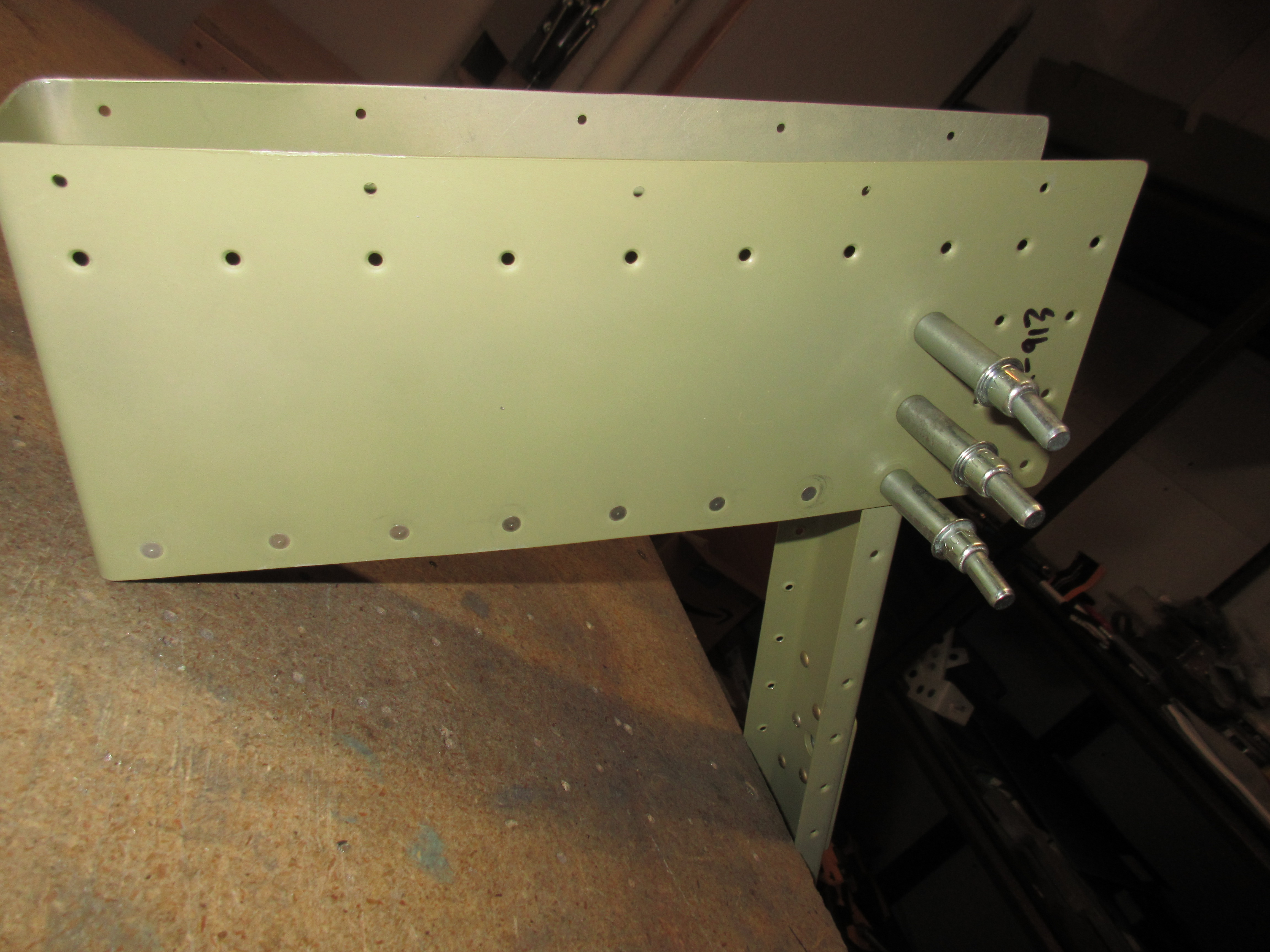
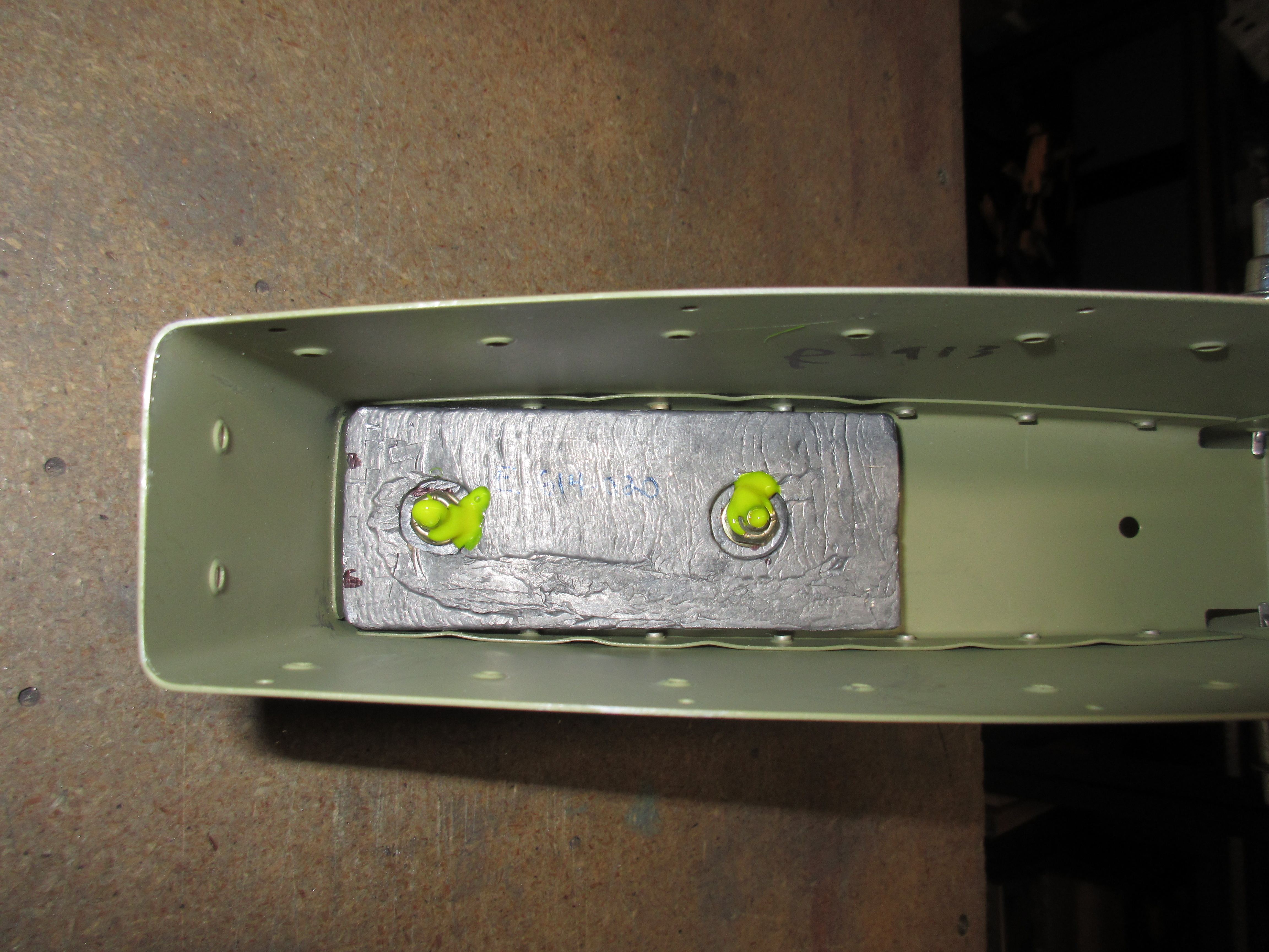
The last step on this skeleton was to install the lead counterbalance weight. I had pre-drilled and countersunk it a few weeks ago, but I still needed to do a little trimming to get the counterweight to fit around the rivet tails that were now sticking inside the skeleton. I didn’t have to remove much material, so the balance shouldn’t be affected. Then I secured the weight with the AN509 screws and torqued them down to 30 inch/lbs. This is the 25 inch/lbs that is called for, plus the drag of the nylon lock nut, which I measured at about 5 inch/lbs. I followed that up with a little torque seal to mark that I had them torqued, and also to show in case the screws start to work loose.
I called it a night at this point. I have a full rudder skeleton, and the next step is to cleco on the skins and start getting them ready to rivet, and then place the end rib on the top. In the next session, I will cleco on the skins and make sure every thing is still lined up, and then use one of the skins as a guide to drill some aluminum angle for the trailing edge.
Heres all the photos from tonights work:
And the Google Photos link: https://goo.gl/photos/SRSXVZCsuYNEQqeY6
Hours Worked: 4.5