Ordered the Wings!

I have submitted my order to Vans for the wings!  I have been working with a few folks over the phone discussing a few options, substitutions and additions to my wing kit, and finally got to the point of getting an order completed.  I am still a bit surprised at just how “old school” Vans is in this regard.  Things are done very much at a slow pace, and usually via snail-mail or fax.  I mean, this is 2017, do people still use faxes?

Never the less. I have decided on adding a couple extra longerons to my order.  These ship with the wings even though they are for the fuselage, to save crating and shipping charges. They are pretty cheap, so I figured I’d order a few extras just in case, and save on the shipping costs. I also decided on upgraded the standard fuel caps to the nice locking deluxe units, and I also added some extra angle aluminum and a few other bits and bobs to make things cheaper to ship.

Here is a spreadsheet I came up with to help me on my order:  https://docs.google.com/spreadsheets/d/1xvkFqz–8bHhM5vU3ZT5DI_iRKh0t4POcf_eJvk-3Hw/edit?usp=sharing

I am waiting on my invoice to get finalized, and then a crating date to be selected.  Then I will pay the rest of the monies, and the kit will be on its way.  It’s looking like an 8 week-ish lead time before they get here.  I wish I’d have ordered them sooner.  Thats it for this entry, no hours being added to the build log, as this is just paperwork.  I did add a new “Wings” category 🙂

Fitting The Elevators to the Horizontal Stabilizer

The empennage kit is wrapping up, and almost complete at this point.  All the major assembly is done, and now its just fitting the parts together and lining up the hinges to drill the elevator horns.  The first thing to do is make sure the eye bolts on the elevators are threaded in to the proper starting depth.  Van’s gives this dimensions in the plans, and I used a dial caliper to get the correct measurements.  After setting and adjusting the eye bolts to the proper thread depth on each elevator, it was time to re-arrange some furniture in the shop to mate the elevators to the horizontal stab.  Here’s how it ended up:

I moved my work benches so that I could drop the elevator horns between them, and then I could slide them back to the table edge to get full movement of the elevators to test their angles. Next up, I fit the elevators in their mounts, and marked the skin so that it could be trimmed to provide the 1/8″ clearance around the elevator horn.

Once I had my marks made, I used a #40 drill to drill the corner so it wouldn’t crack.

Then I snipped away the excess using the tin snips.

Now that I had both the top and bottom done, it was time to knock the rough edges down, and file the corners smooth.  A plain old bastard file made quick work of this, and I am pretty happy with the way it came out.

Once the left side was done, I moved over and did the same exact thing for the right side with equally satisfying results. I think at this point, I am getting the hang of sheet metal work! I am doing work that I’d be proud to show at Osh Kosh 🙂  Then, I decided to go ahead and re-fit the elevators to make sure all the clearances looked good, and that the elevator would move through its entire Max deflection as prescribed by vans.

I made a cheap little tool to help get the bolts inserted into the hinges.  This is a super tight area to work in, and there is hardly any room to get fingers in there to hold the bolts and insert them.  So, here is what I came up with:

Yep… that is a piece of Gorilla tape on the boxed end of a wrench! It worked pretty damn good!  I was able to snake the bolt down into the access hole, wiggle it into the hinge and fully insert it while holding the elevator in position.  Once I had the bolt in place, I could just twist the wrench and tape off the head and the bolt stayed right in place. I didn’t use any washers or nuts, since I am just test fitting everything together for now.  I want to make sure I have the eye bolts set correctly, and that the elevators can move their full range with no binding.

After checking both sides for binding, I used a simple little protractor to verify that the elevators each could move through their max deflection of 30 degrees up and 25 degrees down as instructed by the plans.  Being happy that they moved great, I decided to call it a night for now.  I still need to double verify using my digital angle finder and micrometer to make sure everything is perfect and then I will drill the elevator horns.  Thats work for another session! Here’s all of tonights photos:

This slideshow requires JavaScript.

Google Photos Link:  https://goo.gl/photos/AJgKvyhtcwidDZKn6

Hours Worked: 2

Finishing the Rudder

While Tammy and Acacia were taking a nap, I decided to sneak off to the shop and get some work done on the airplane.  Since the trailing edge of the rudder was completed a few days ago, its time to finish it up, and that means bending the leading edge and threading in the mounting hardware.  I started off by bending the leading edges, which is done exactly like the elevators in previous posts.  I used Gorilla tape on the leading edges, and then a piece of wooden dowel rod as a rolling pin to roll the edges gently into a nice curved shape.  

Once both sides have been rolled I had to finish the bends by hand to make sure the skins are lining up with the pre-punched holes, and to make the leading edge bend nice and neat and smooth.  This is not a gentle process, and takes a lot of work to get the metal where I wanted it, but ultimately I got the bends to where I was happy.  Then I used 3/32″ clecos in the #40 holes to hold the bends while I match drilled everything to a #30 hole for the AD-41-ABS blind rivets.  As I drilled the holes, I replaced it with the larger 1/8″ cleco.

Once I had all the holes match drilled, It was time to deburr the holes.  Since this part is hard to get to, I used a scotchbrite pad on all the surfaces I couldn’t reach with my deburring tool and made sure they felt nice and smooth with my fingers before moving on. Once the holes were deburred, I clecoed it all back together using 1/8″ clecos and started the blind riveting process, one hole at a time. These came out looking pretty good!

I decided to go ahead and thread the eye bolts into the mount holes of the rudder and get them roughly into position.  I picked through my hardware bags until I found the proper eye bolts, and their jam nuts, then I coated the threads with a good helping of Boelube to help with the platenuts.  I threaded them all in, and got them to roughly where they need to be per the plans as far as depth.  I will temporarily mount the rudder to the vertical stabilizer in a few days to do the final alignment of the eye bolts, and then tighten the jam nuts fully to set their position.  I am happy with how the rudder came out!

Here is a gallery of all of tonights photos:

This slideshow requires JavaScript.

Google Photos Link: https://goo.gl/photos/BqJkTwTFneTcLm1h6

Hours Worked: 1.5


Riveting the Rudder Trailing Edge

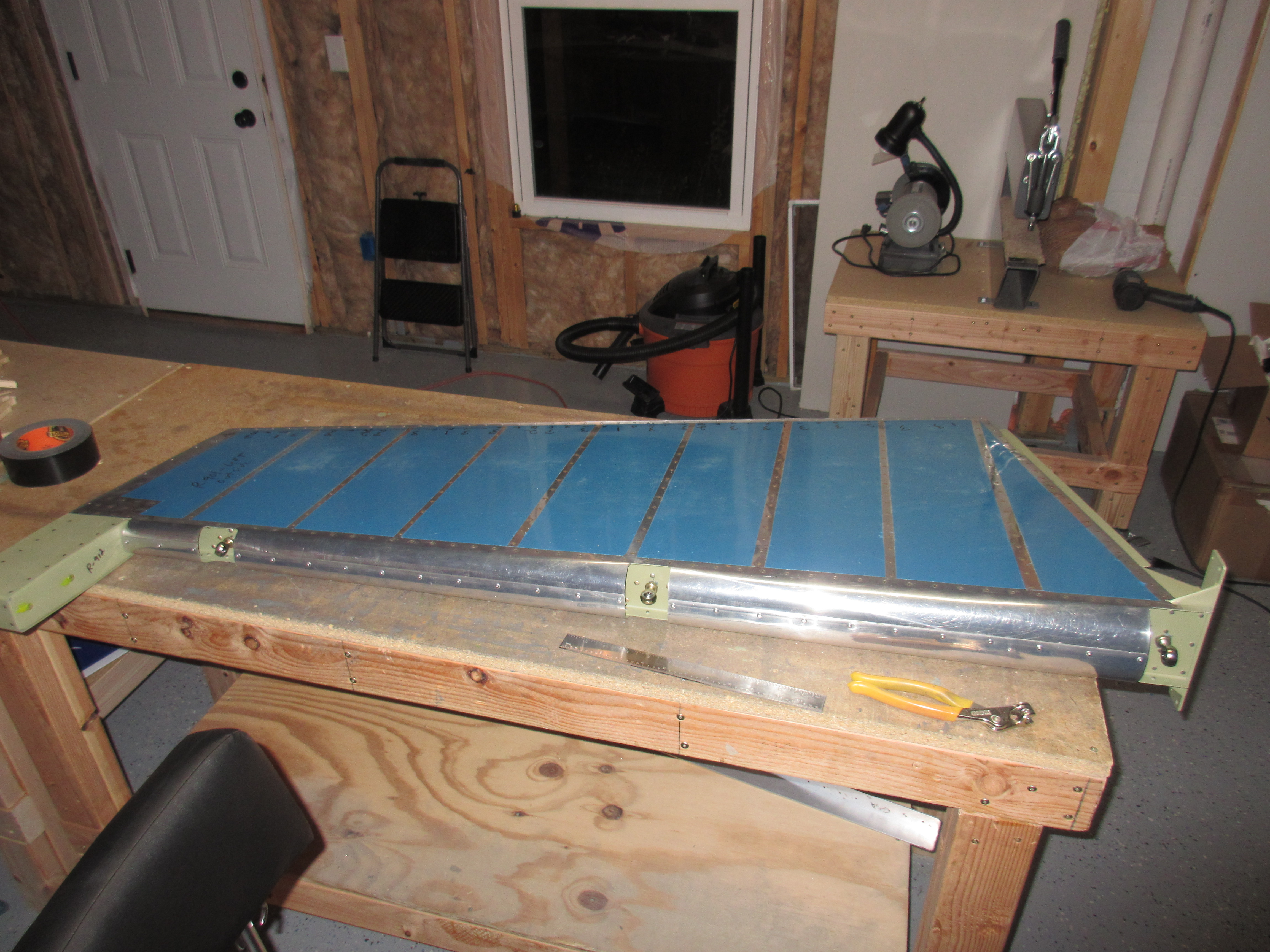
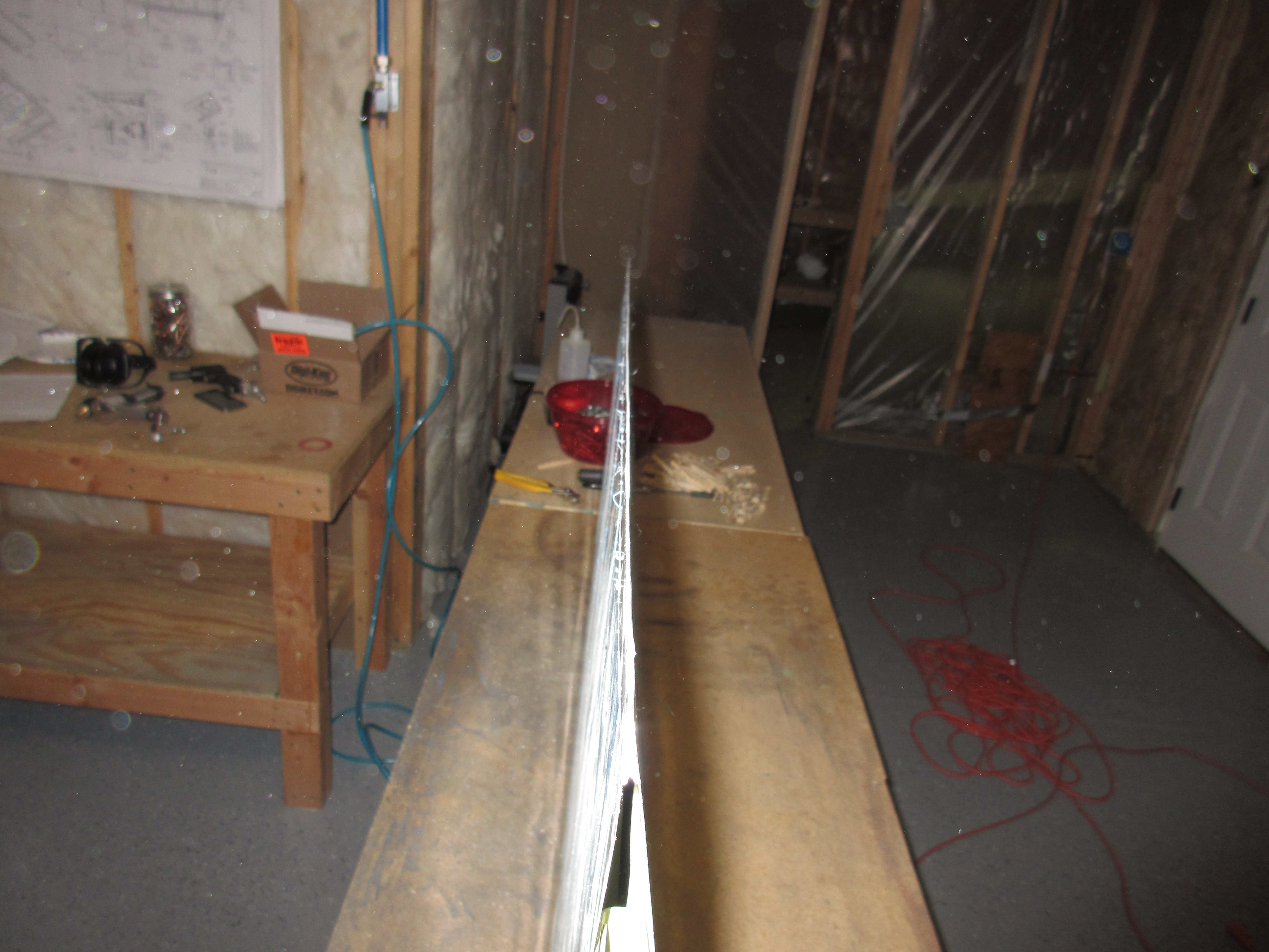
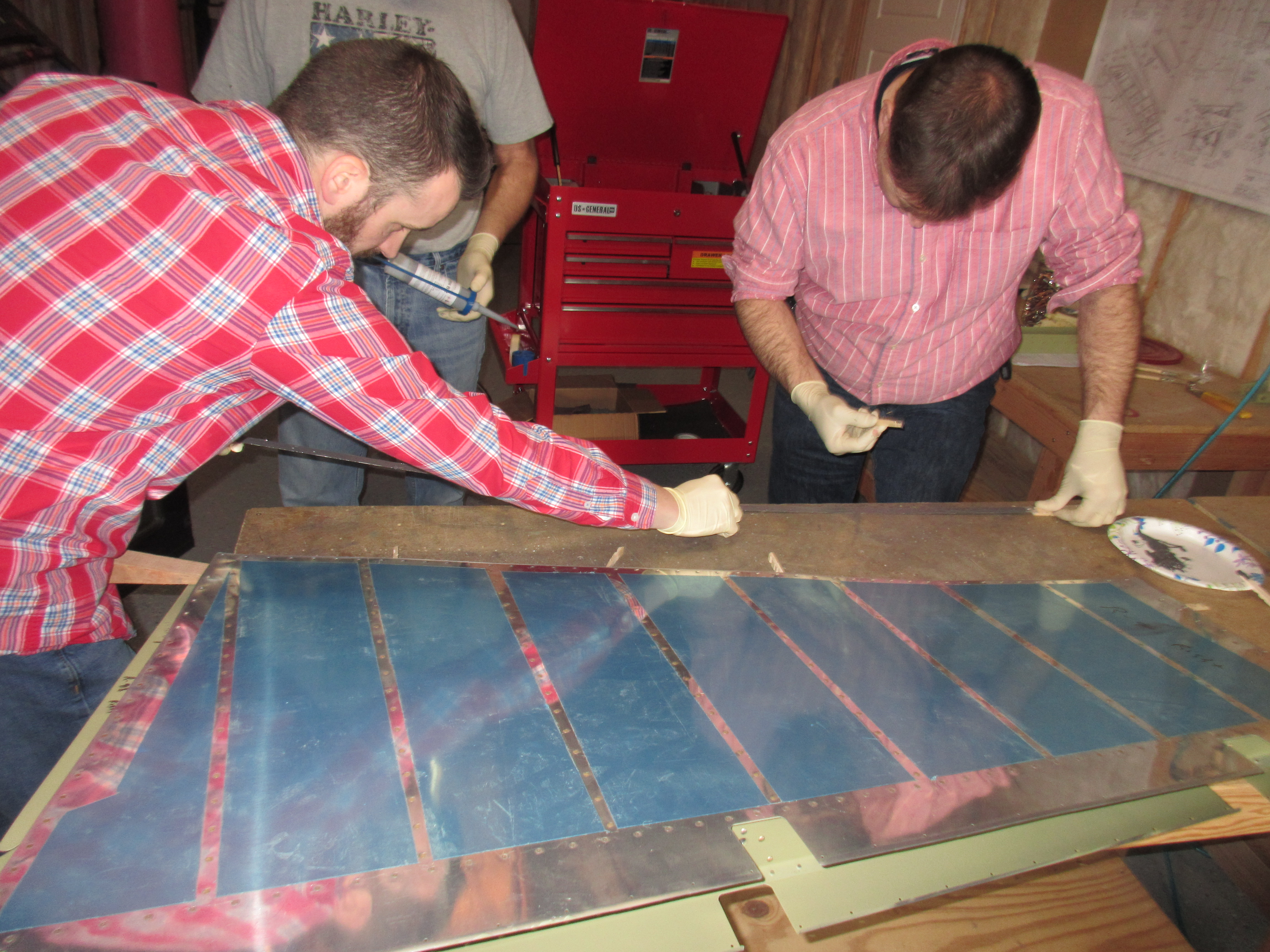
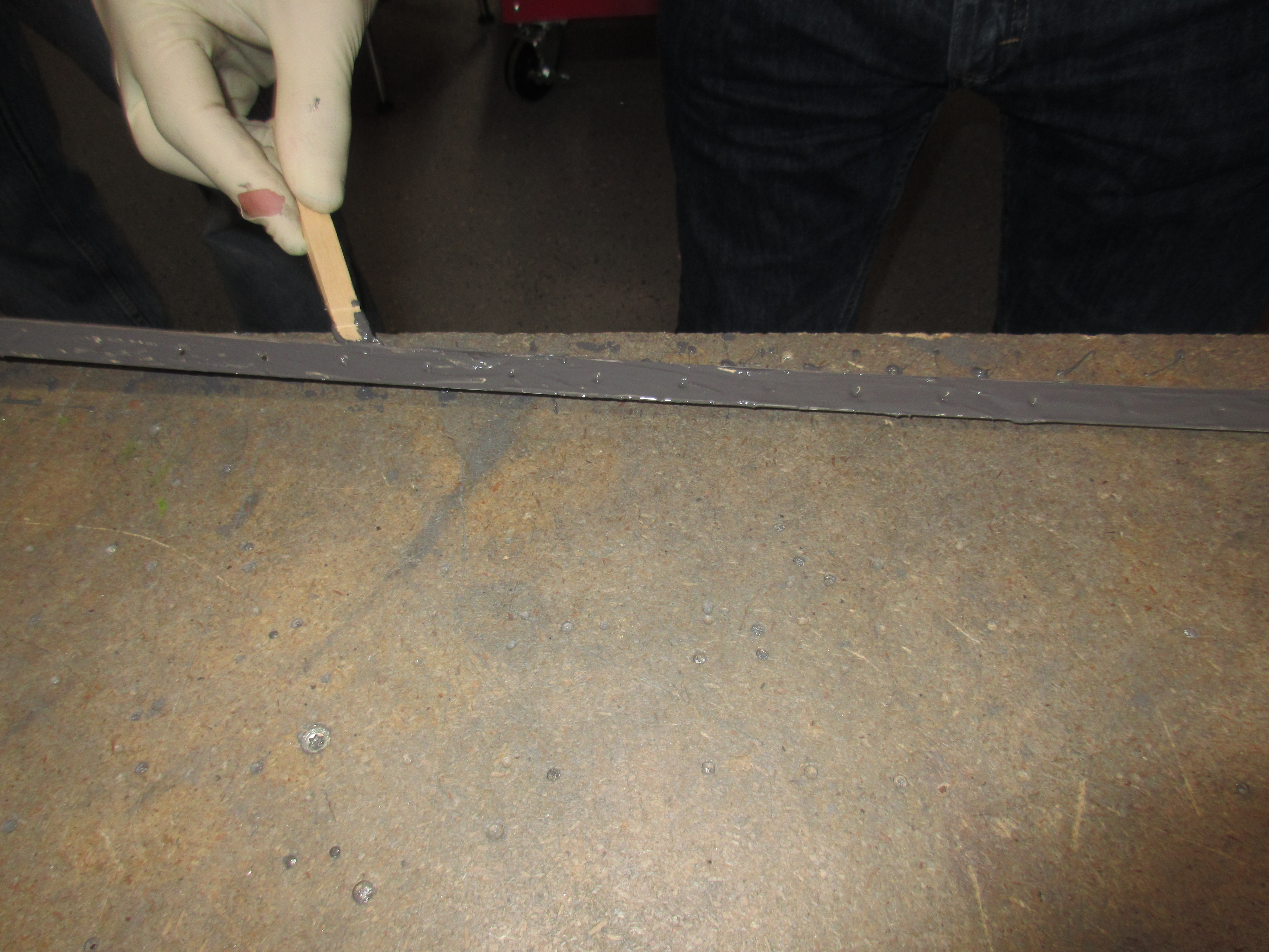
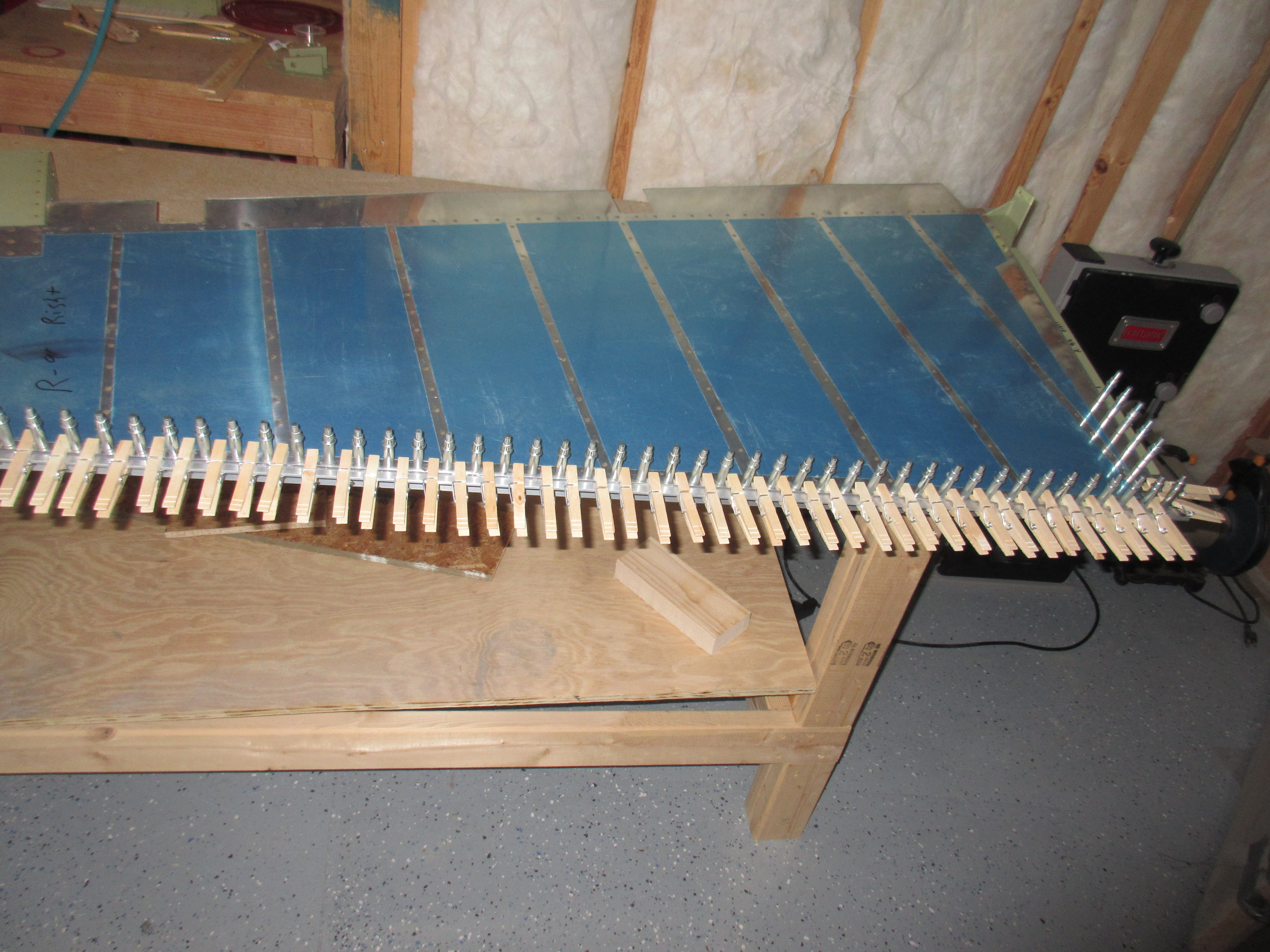
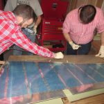
Tonight. I decided to take on the most difficult part of the empennage:  The Rudder Trailing Edge!  This one simple little piece of kit causes the most headache and heartache out of the entire tail section, and for good reason.  If you can’t get a good straight trailing edge on the rudder, you will have a hell of a time trying to get it all trimmed out and flying hands off.  I followed the Van’s recommendation (see previous posts) about using a piece of angle aluminum and Pro-sealing the trailing edge wedge into place and clecoing the trailing edge onto the aluminum angle to help it bond into a nice straight piece. That worked wonderful.  Then I used Van’s suggested method of double flush riveting the trailing edge.

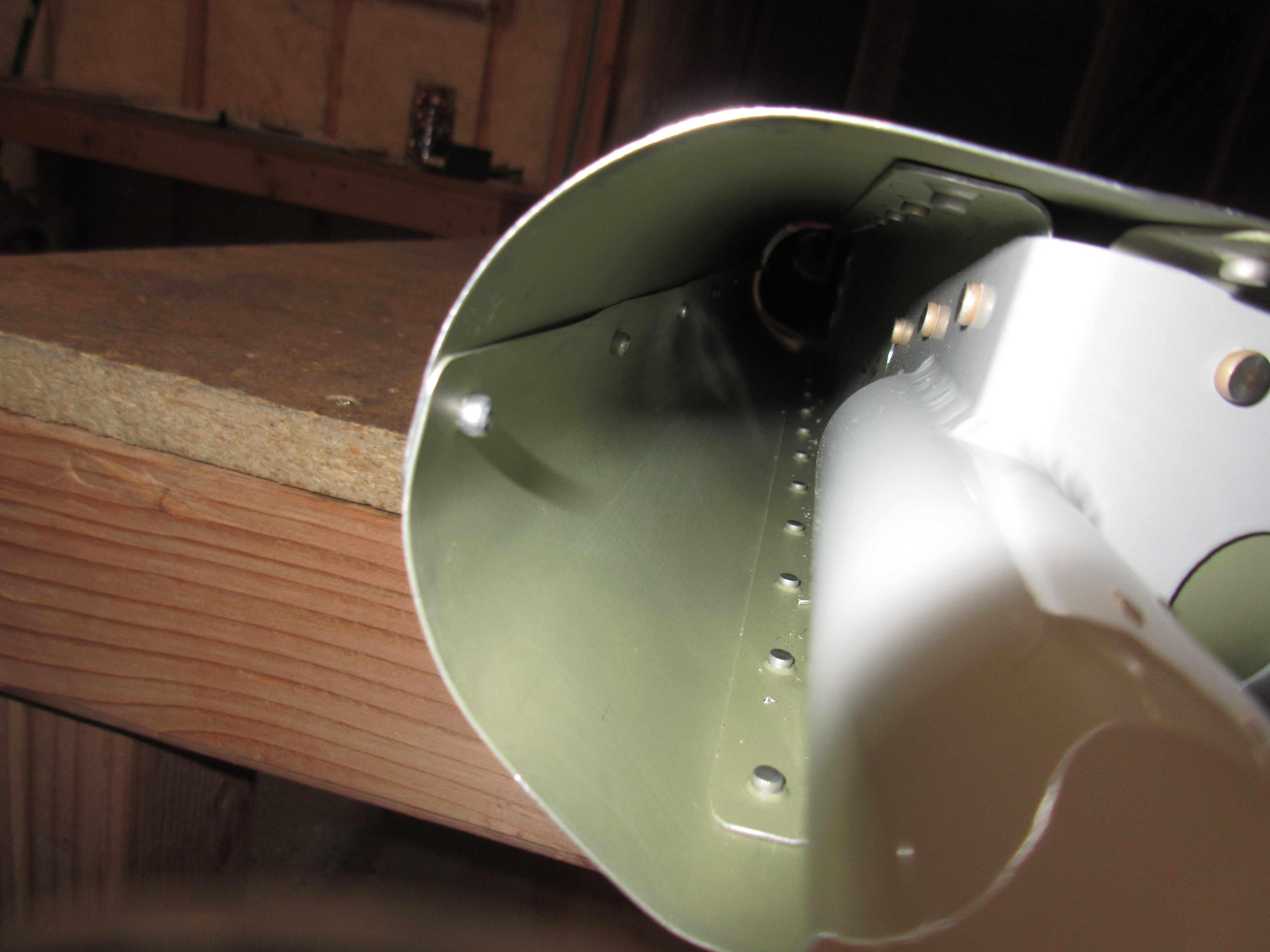
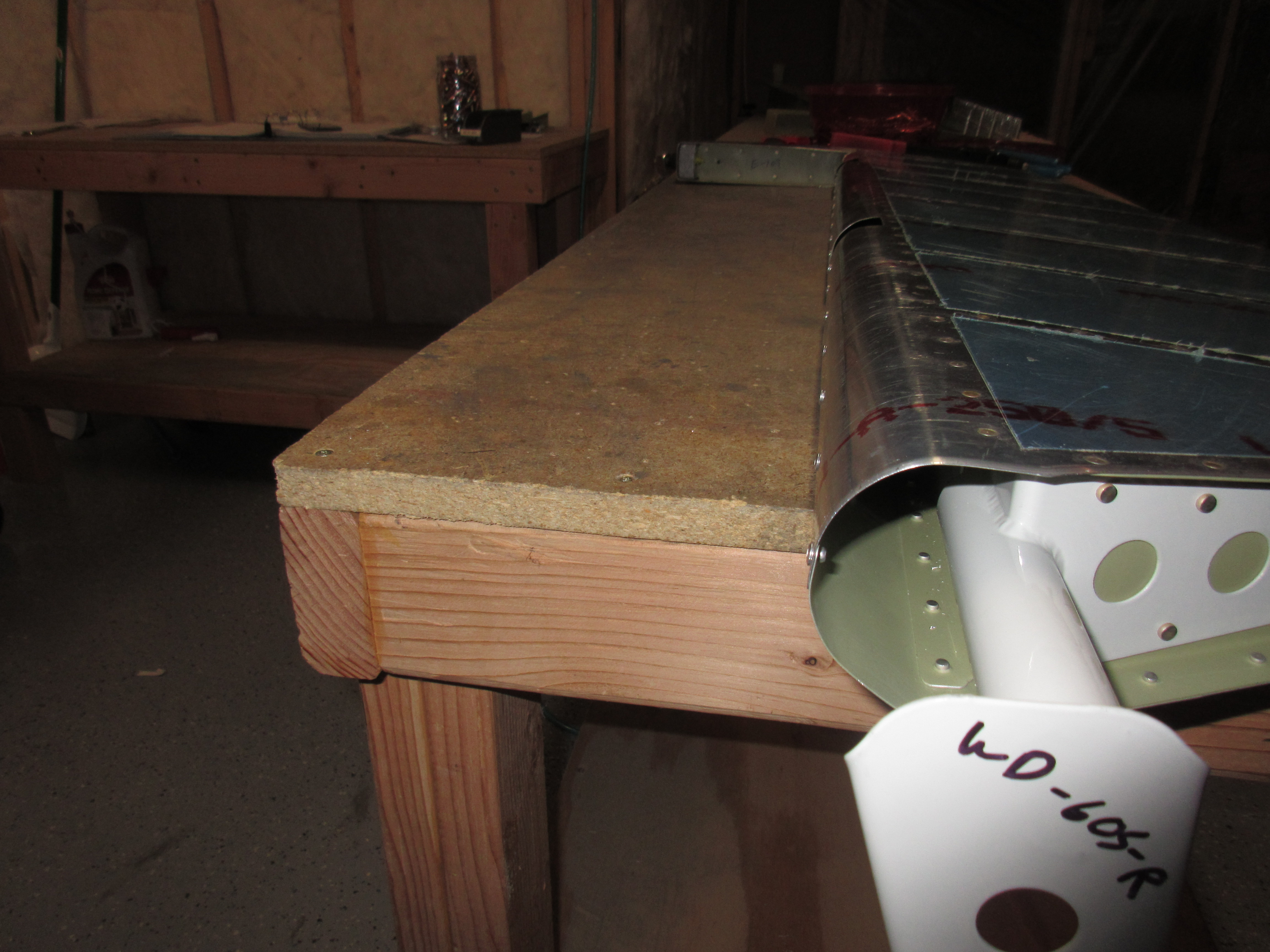
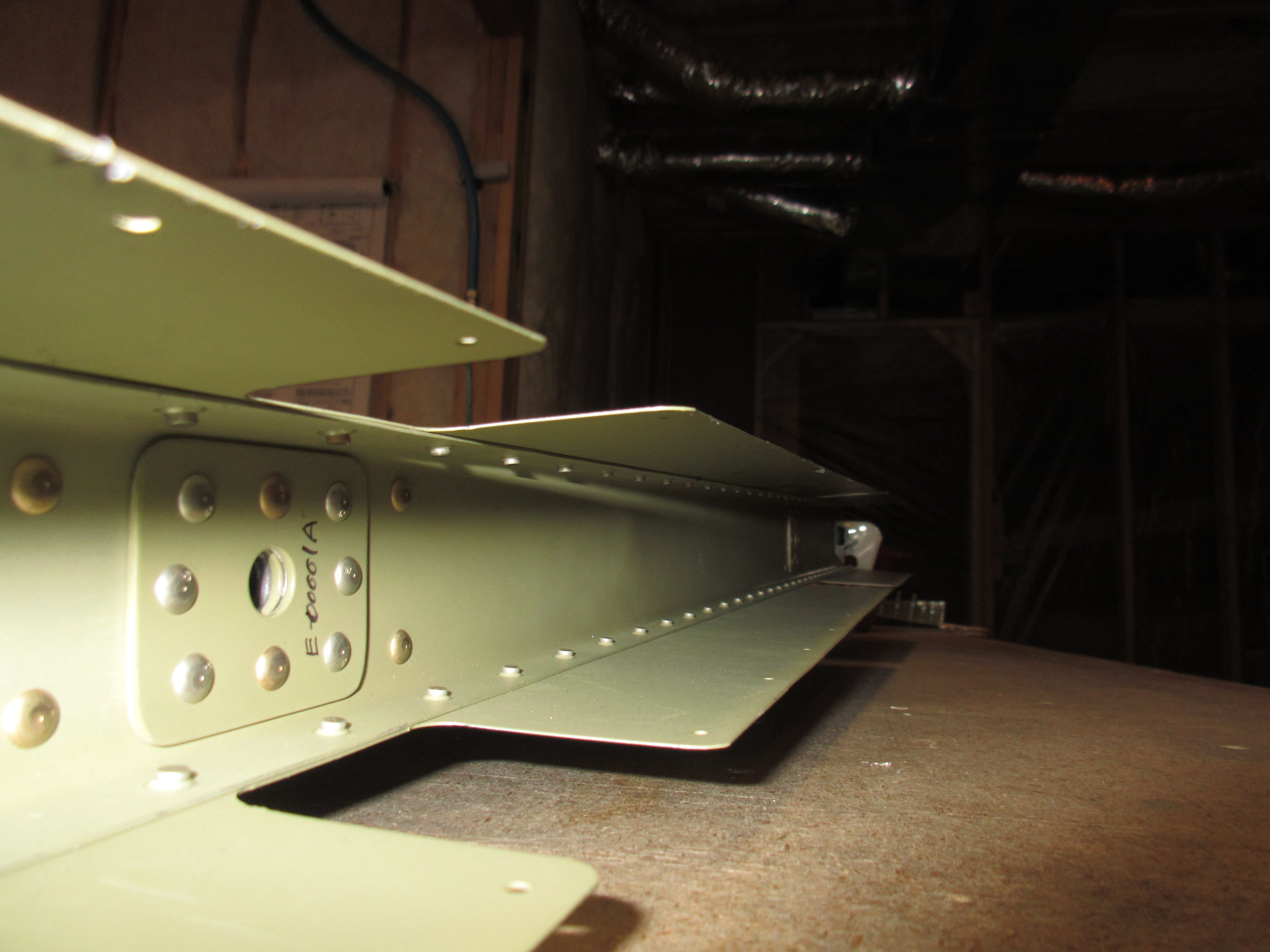
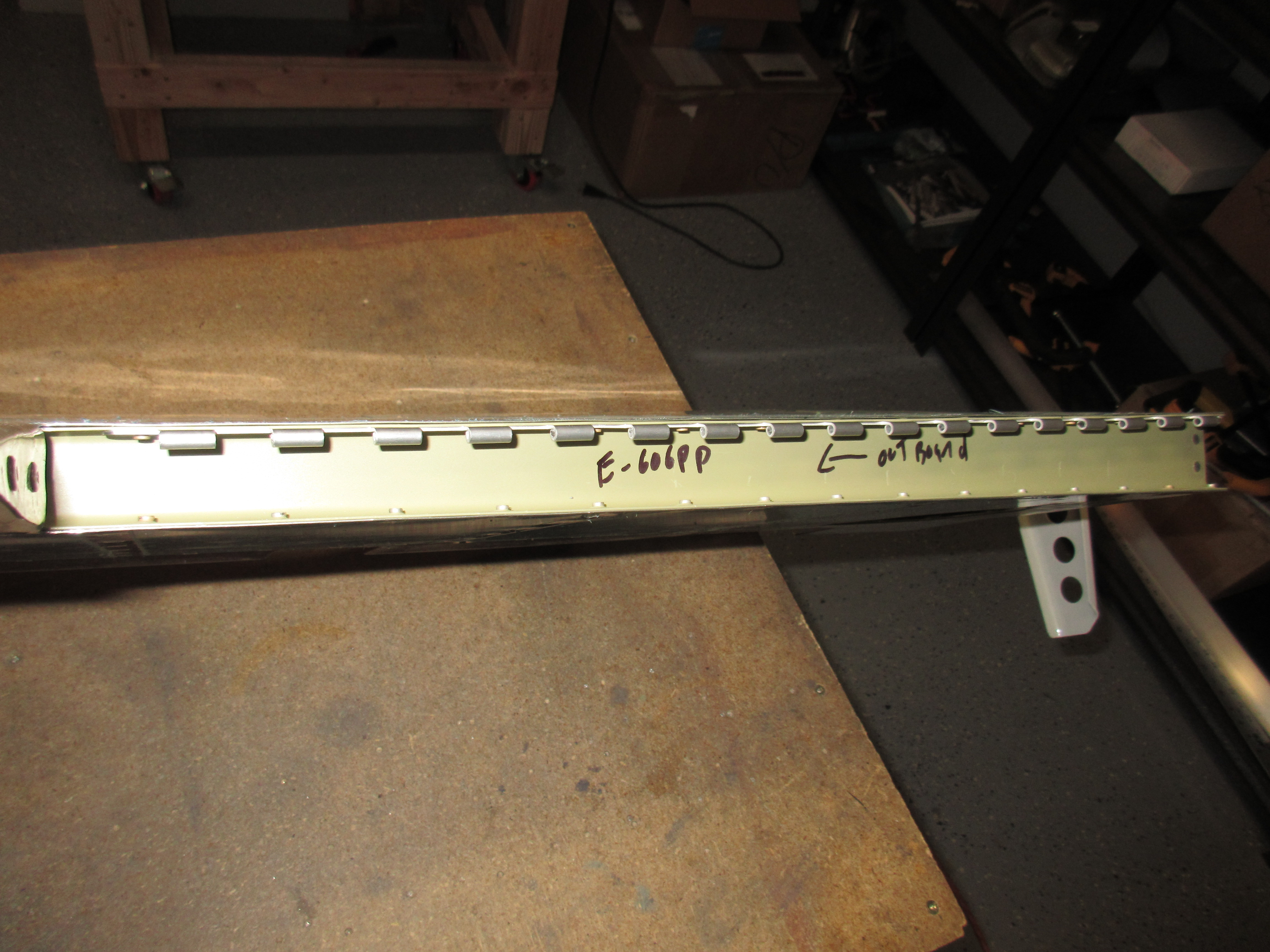
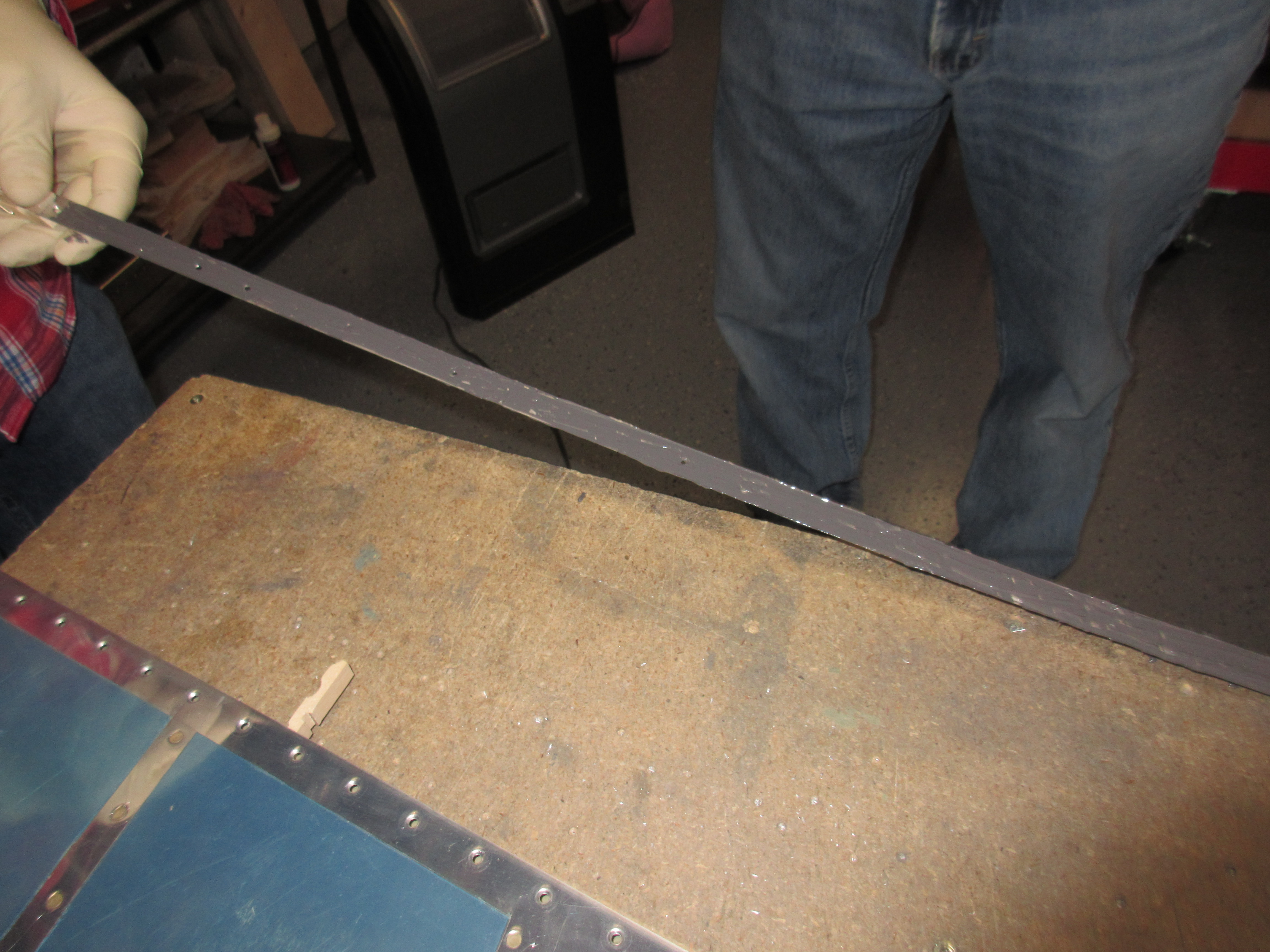
To start off, I had to remove the angle that has been holding the trailing edge in its curing position for the last 18 or so days.  The Pro-seal had squished out a bit, and bonded the trailing edge to the angle, but it was pretty easy to separate and remove the angle. 

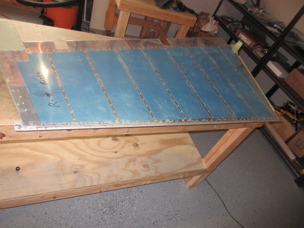
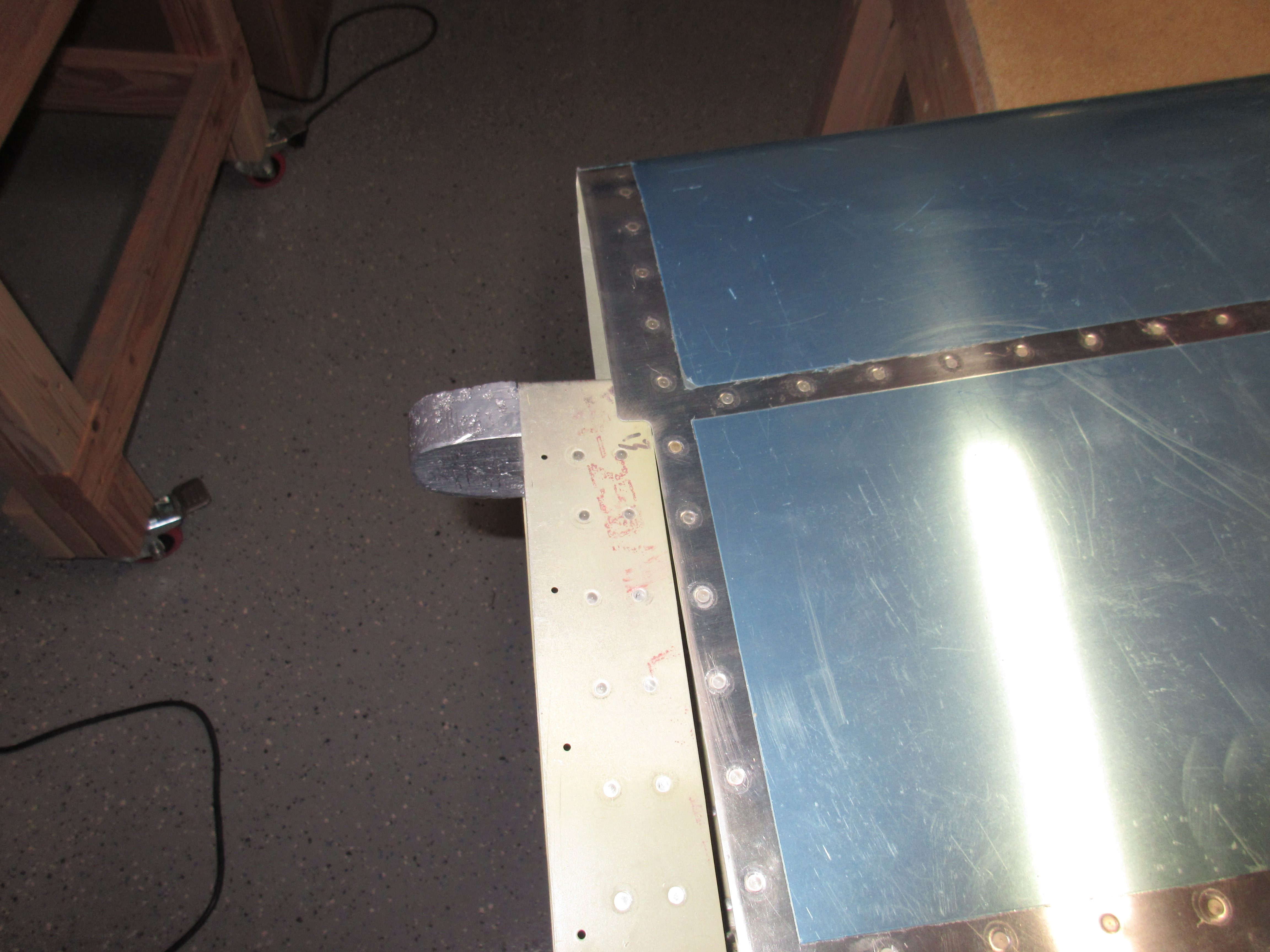
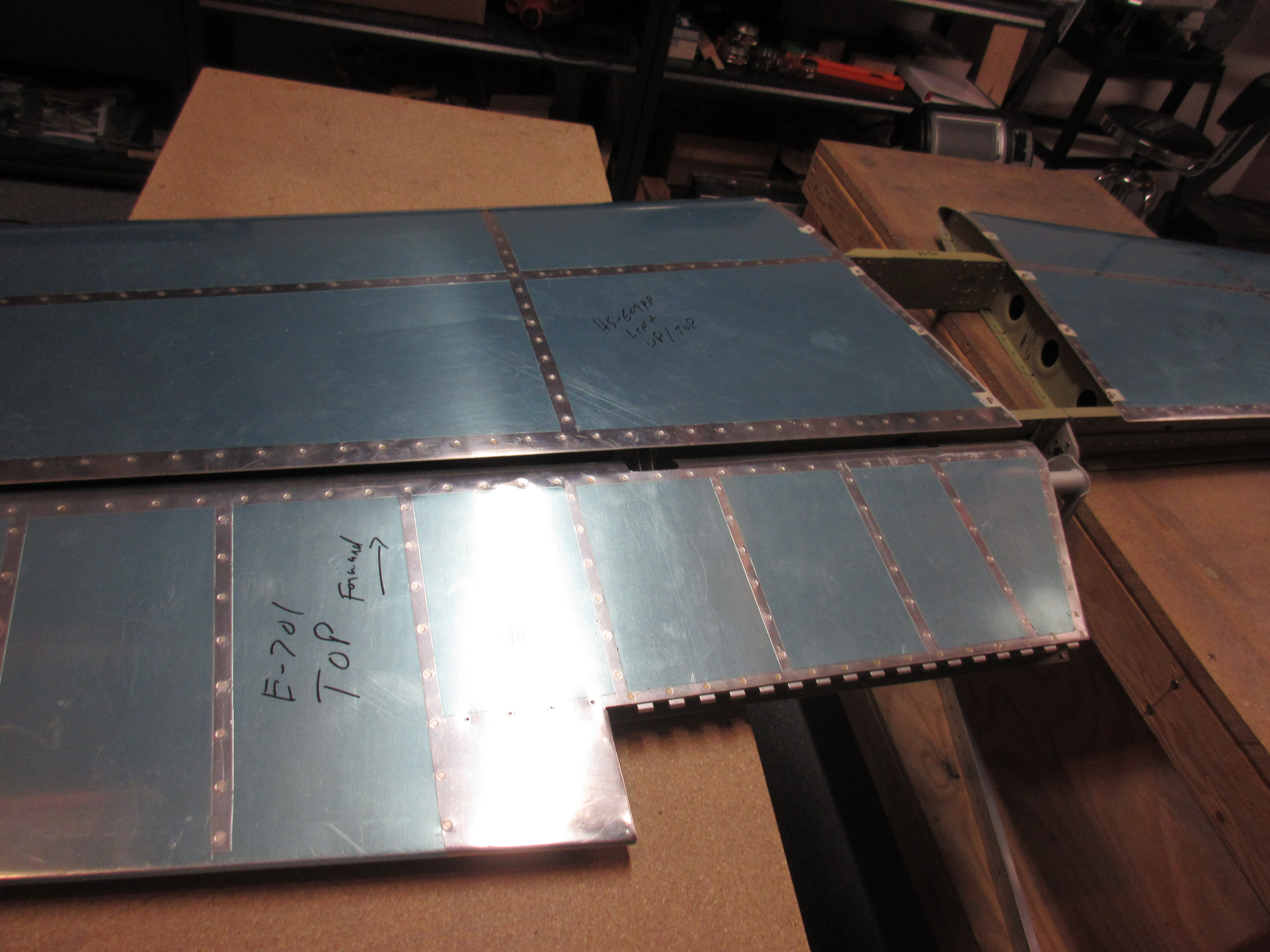
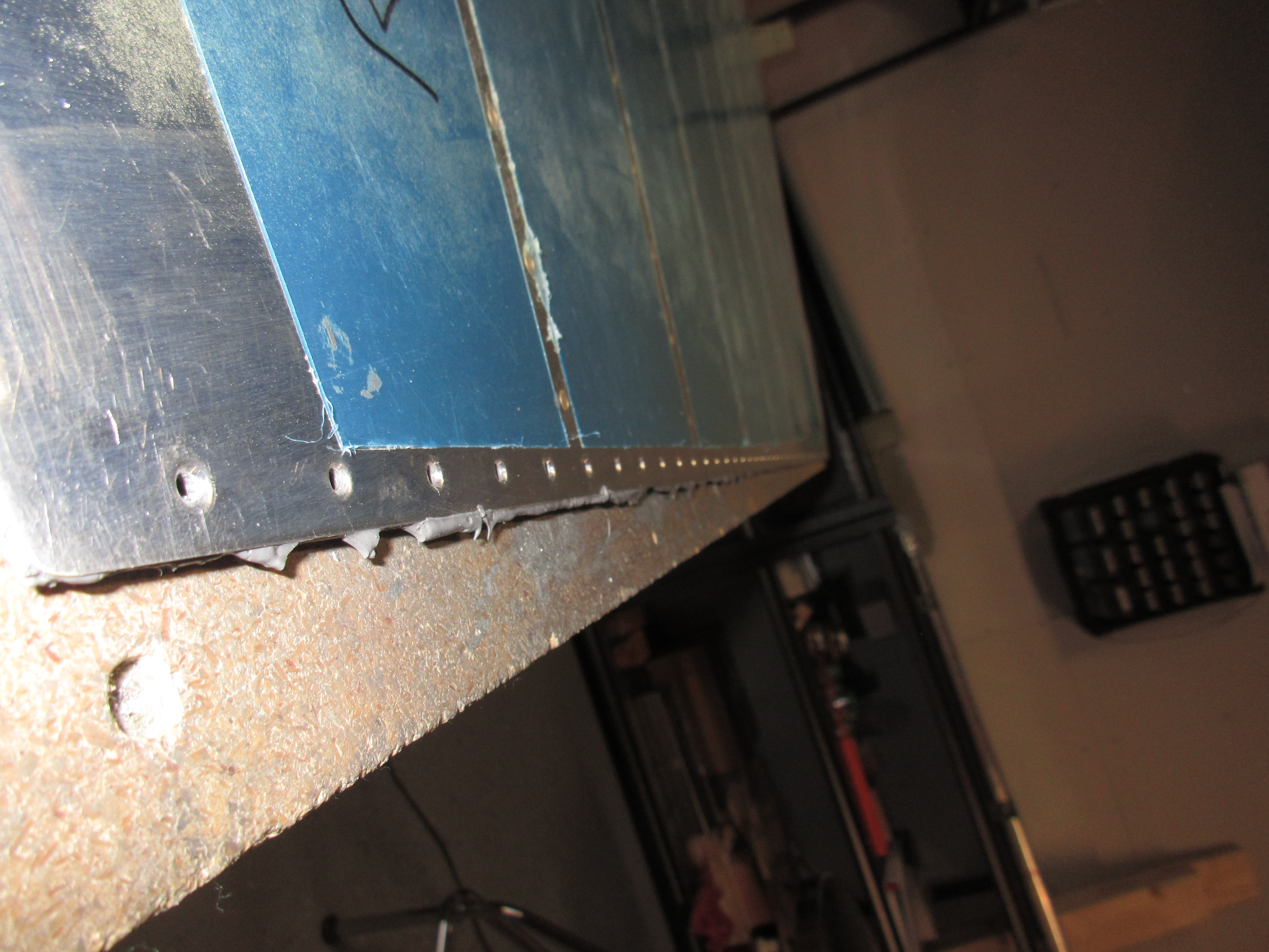
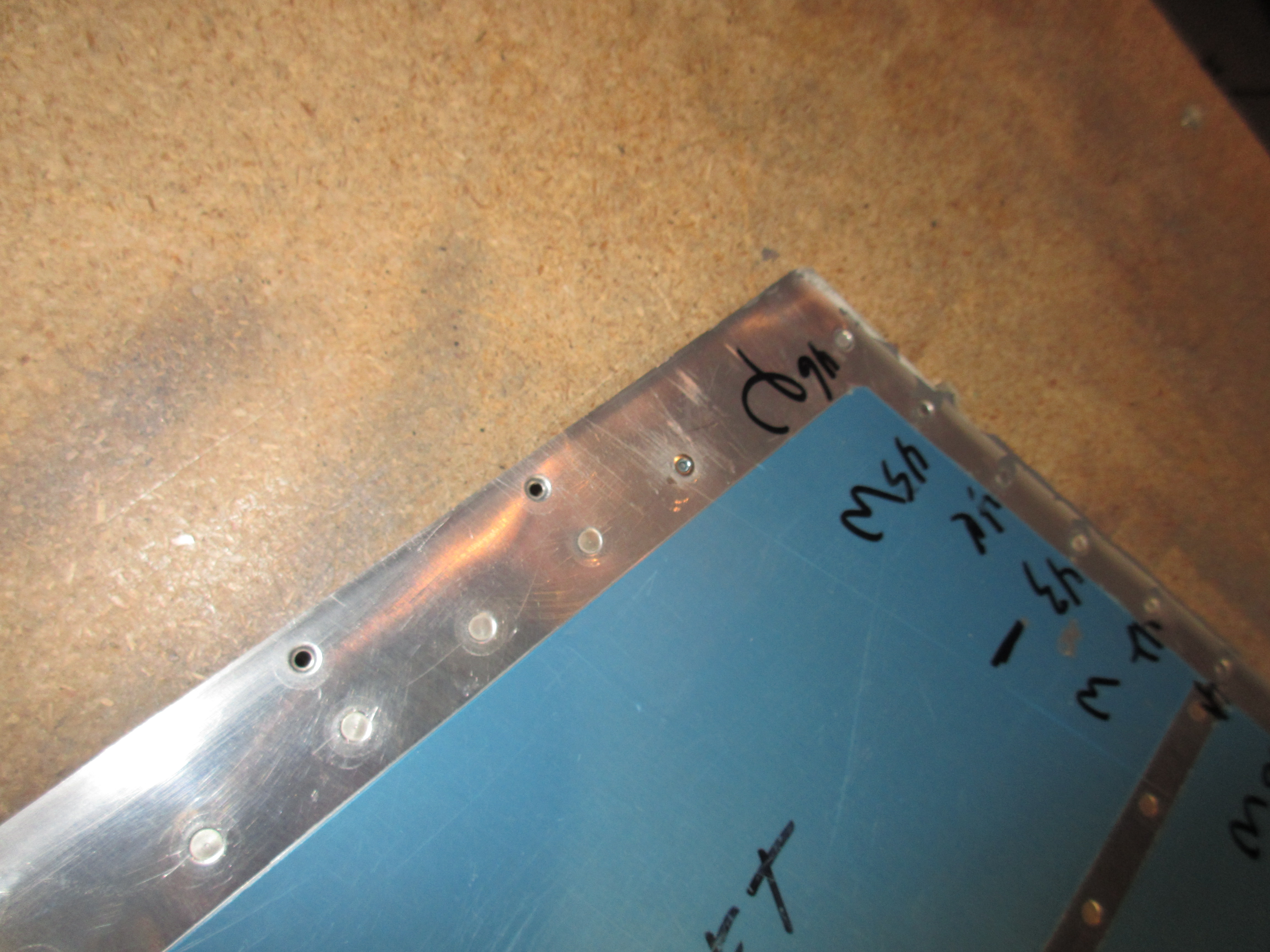
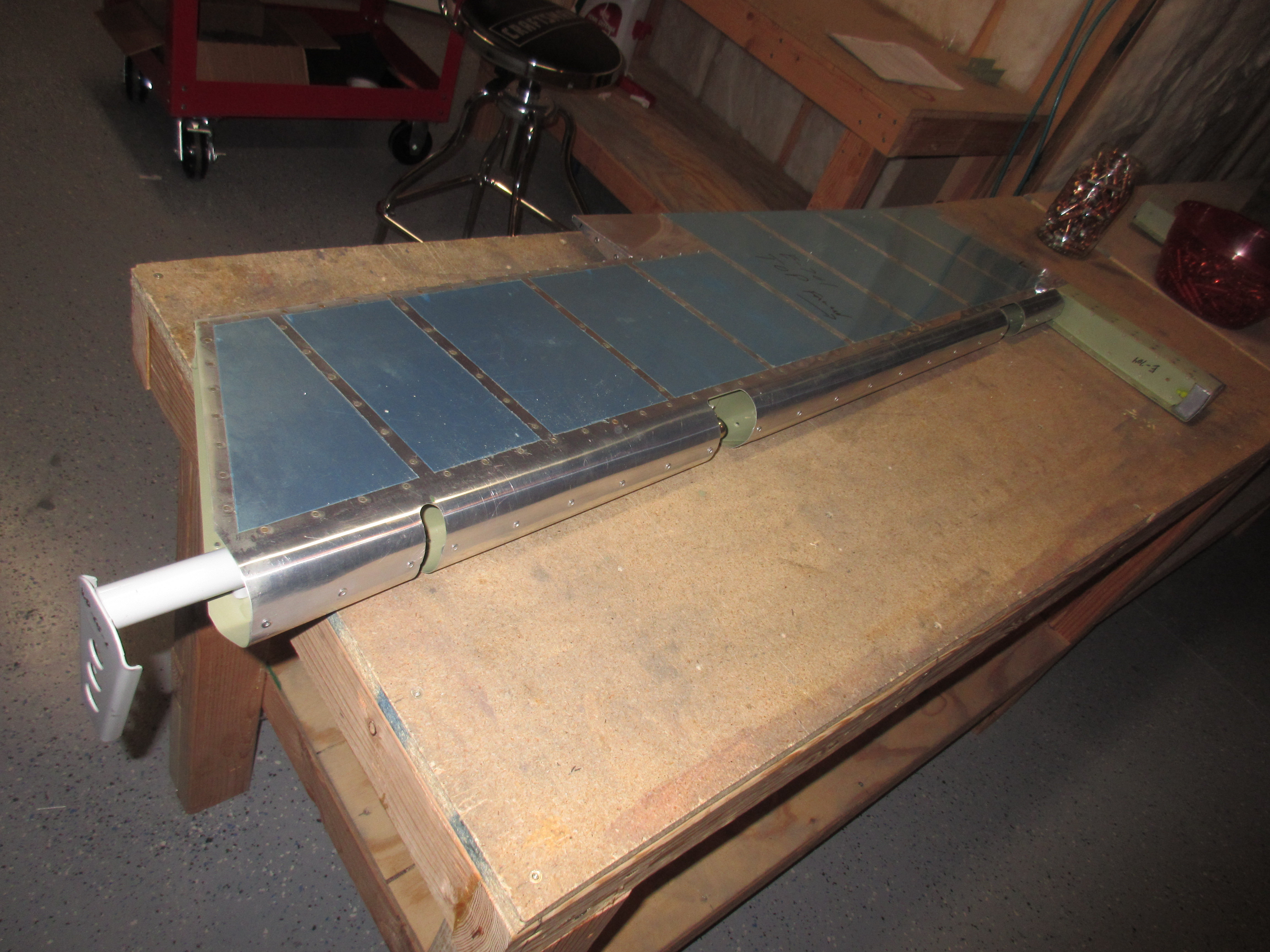
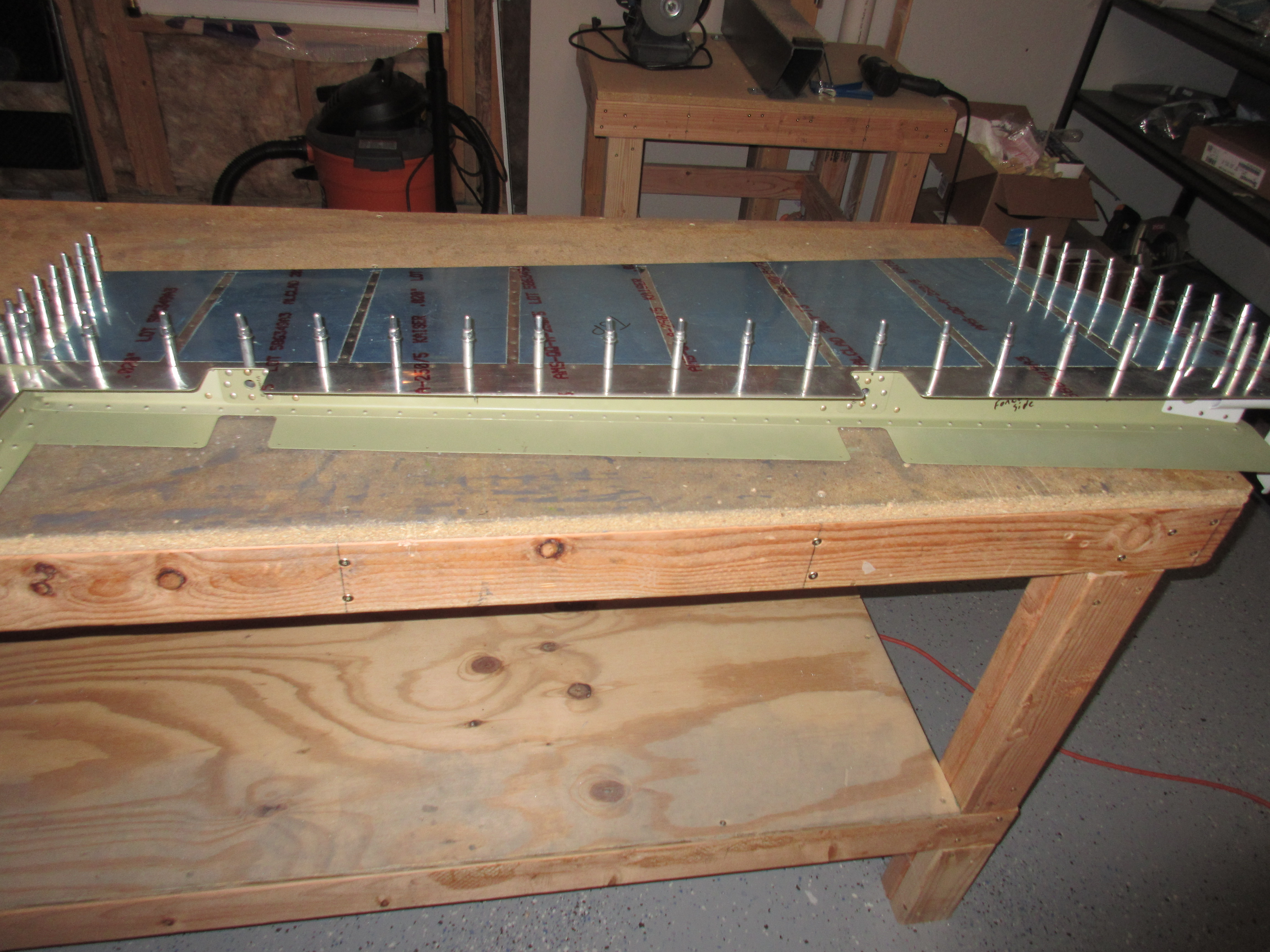
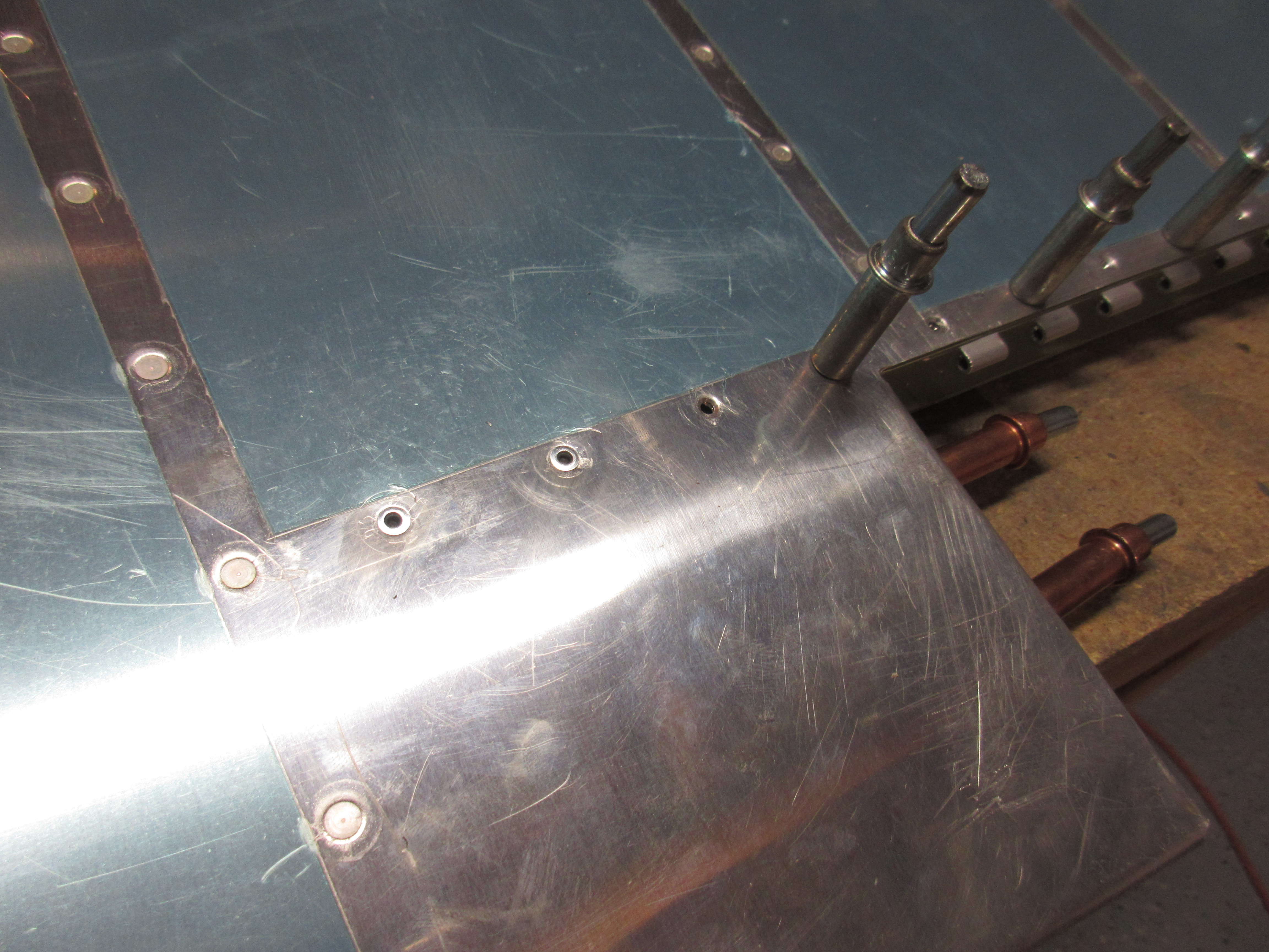
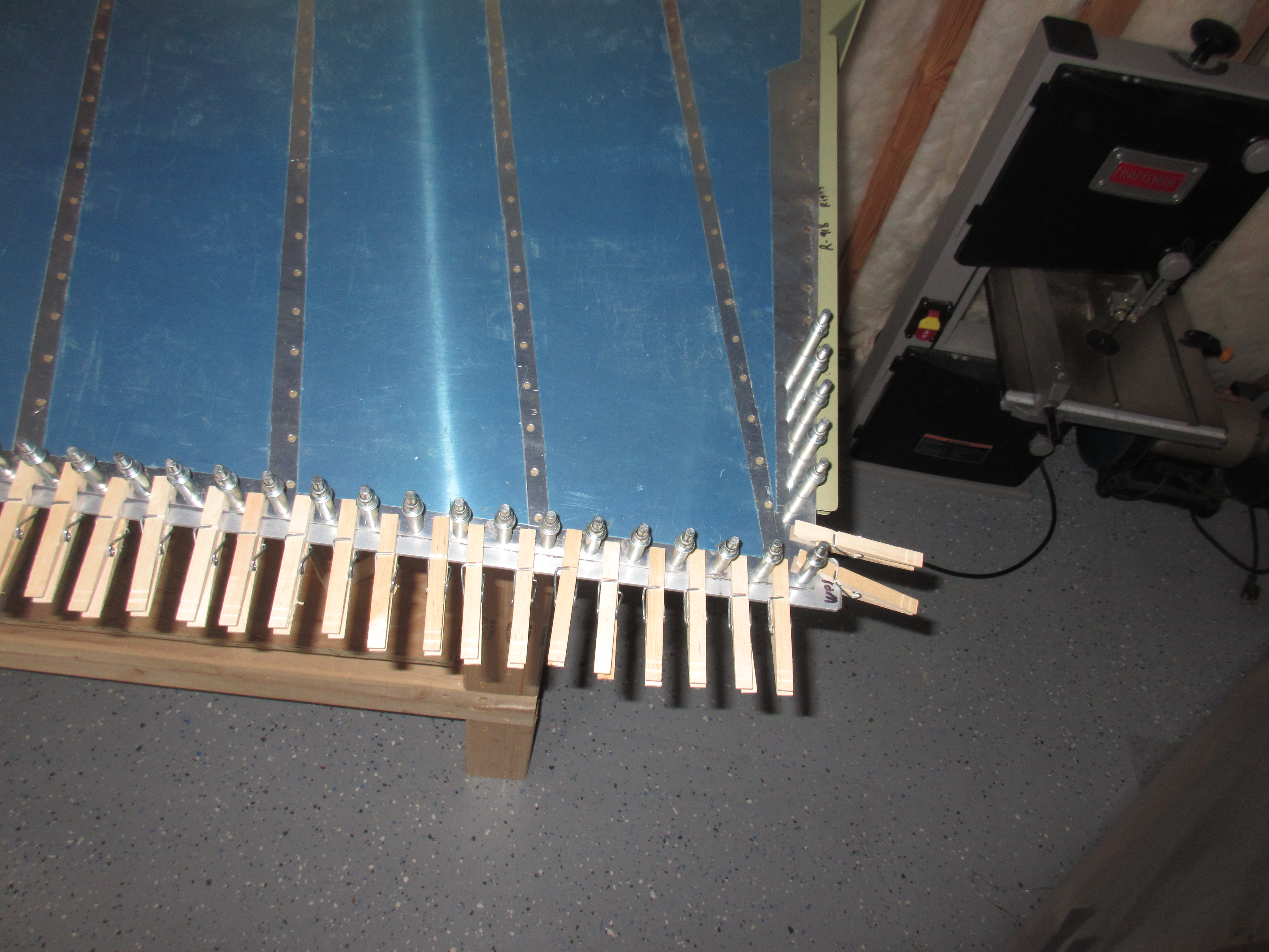
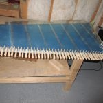
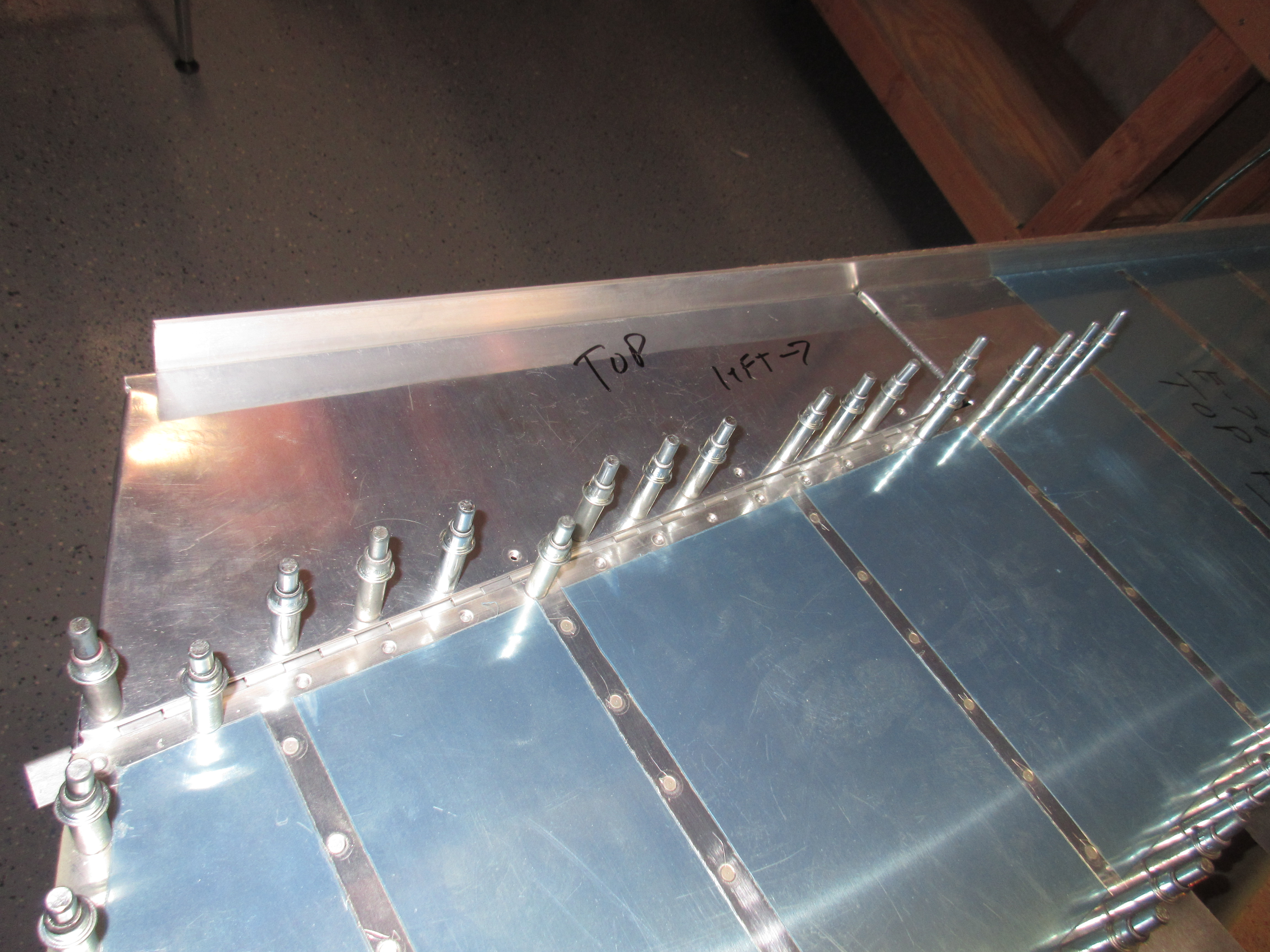
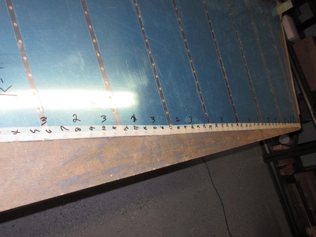
Once I had the angle off, I used a #40 drill bit in my hand to clear out the Pro-seal from al the rivet holes.  On quite a few of these holes, I had to use the deburring tool with very light pressure to remove some of the Pro-seal that oozed out into the dimple.  I also tried to clean up the edges and skin surface so that no Pro-seal would cause the trailing edge to not sit flush against the back riveting plate. I used some acetone to clean off the skin surfaces, because Pro-seal is some sticky stuff! Once it was all cleaned up, I inserted the AN4263-3.5 rivets and used some masking tape to hold the manufactured heads of the rivets into the dimples.

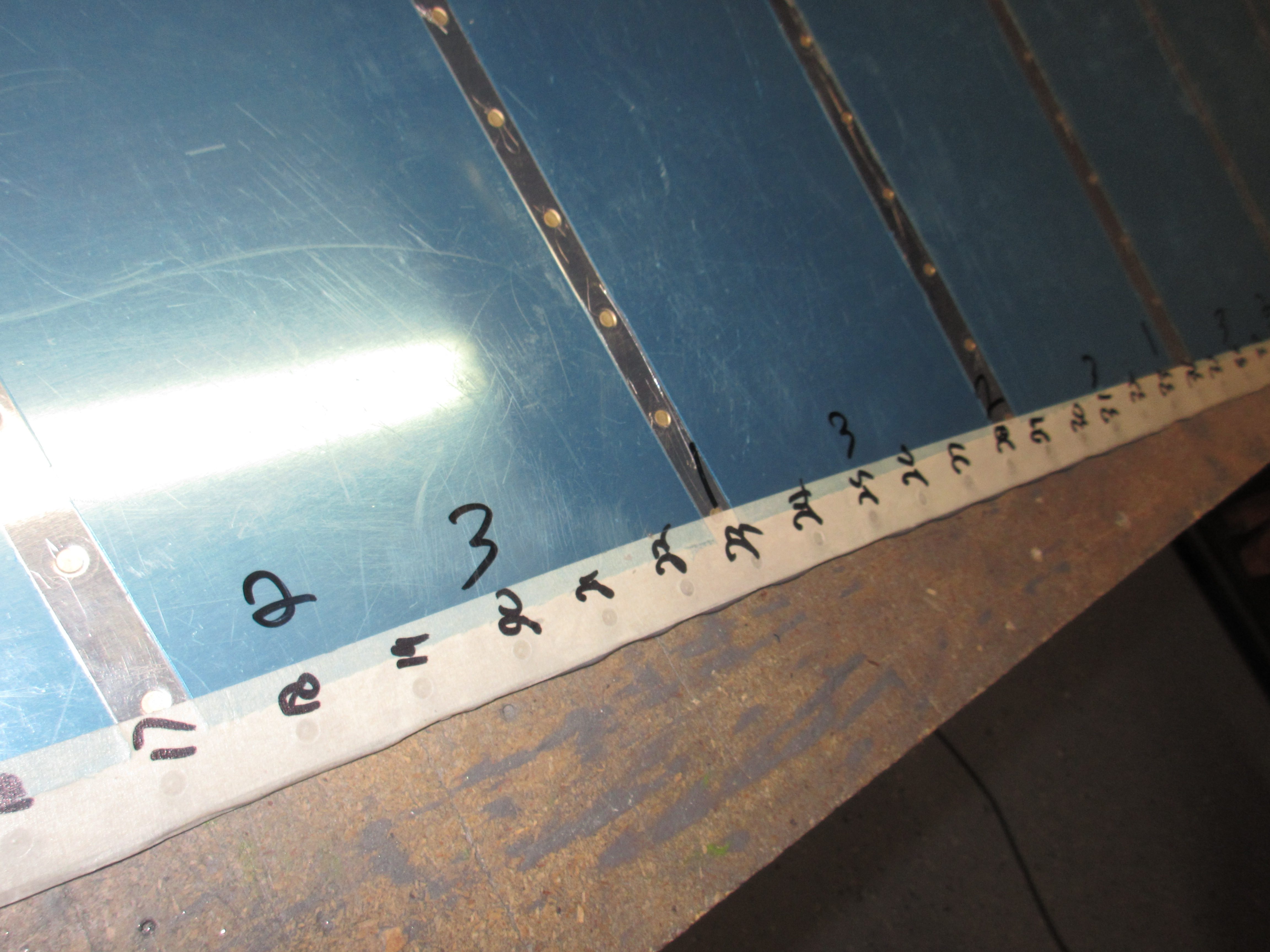
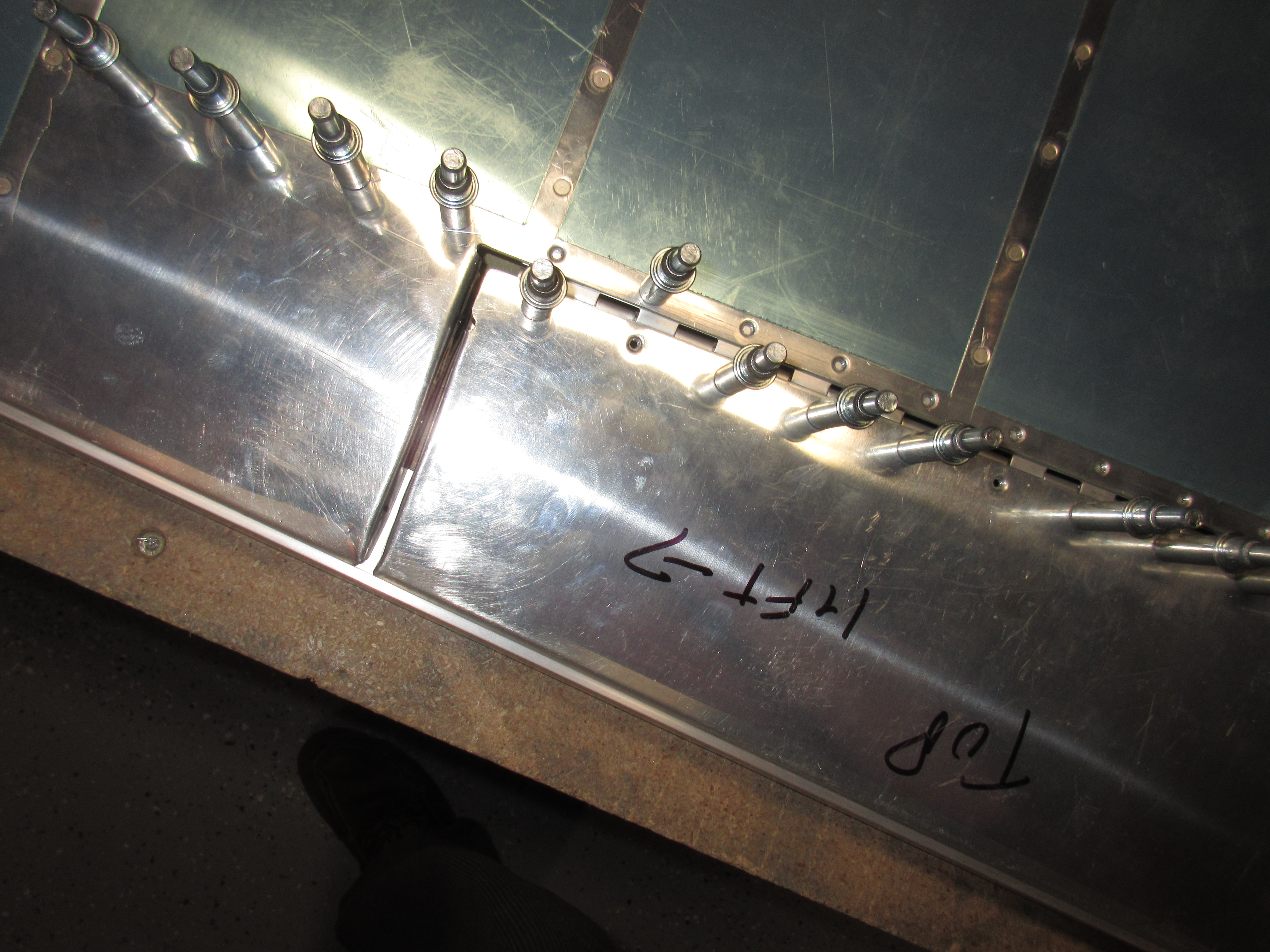
You can also see in the photo above, I numbered every rivet on the tape, and then wrote in my riveting sequence just above the numbers.  Van’s tells us to start off by half-way setting every 10th rivet using a back rivet set.  I started in the middle, and counted every 10th all the way to the top and bottom and marked the with the number “1”.  These would get set first.  Then I counted every 5th rivet and marked its sequence as number “2”.  Then I tried to roughly put my third sequence, number “3”, in between the 1’s and 2’s.

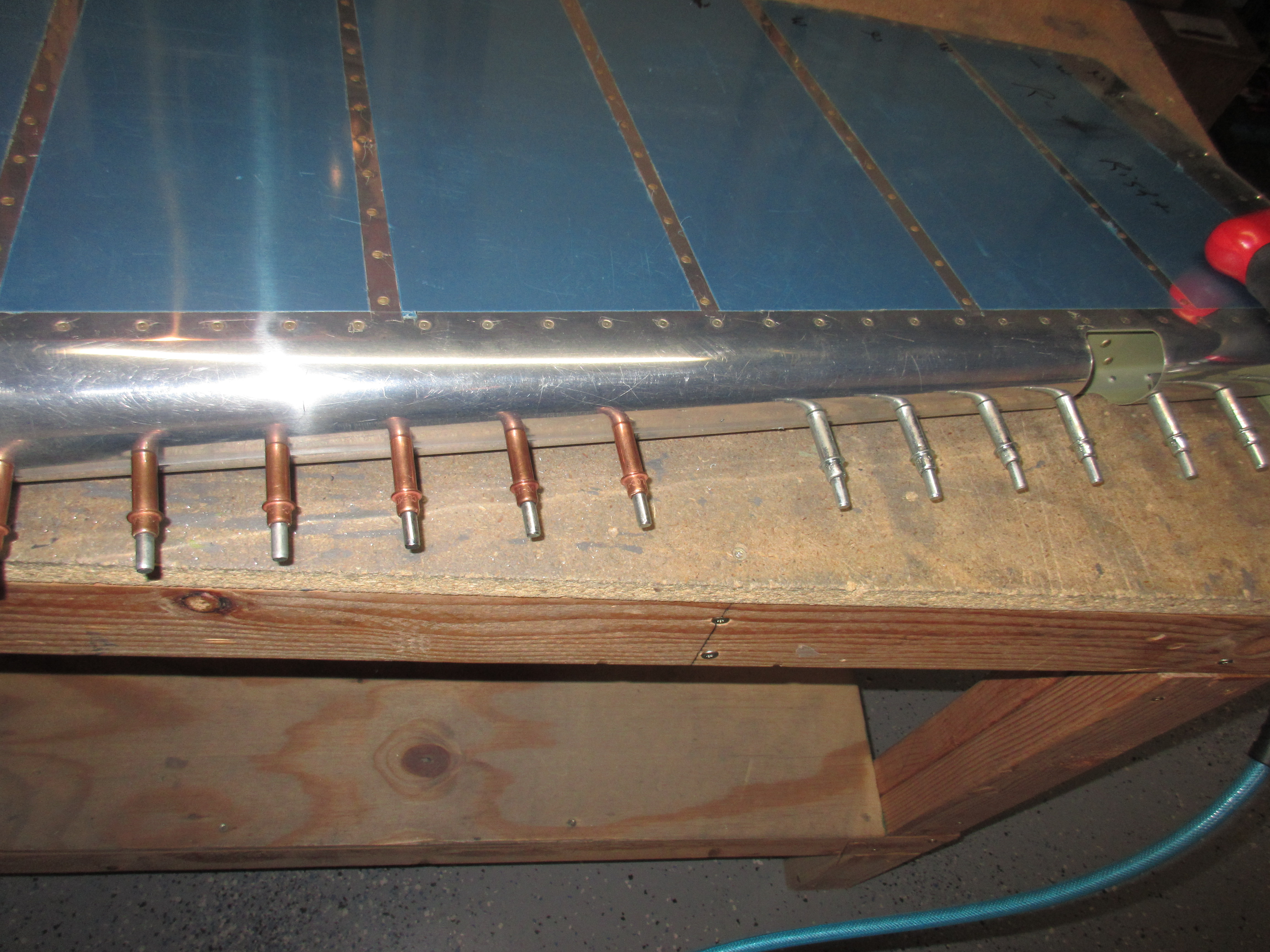
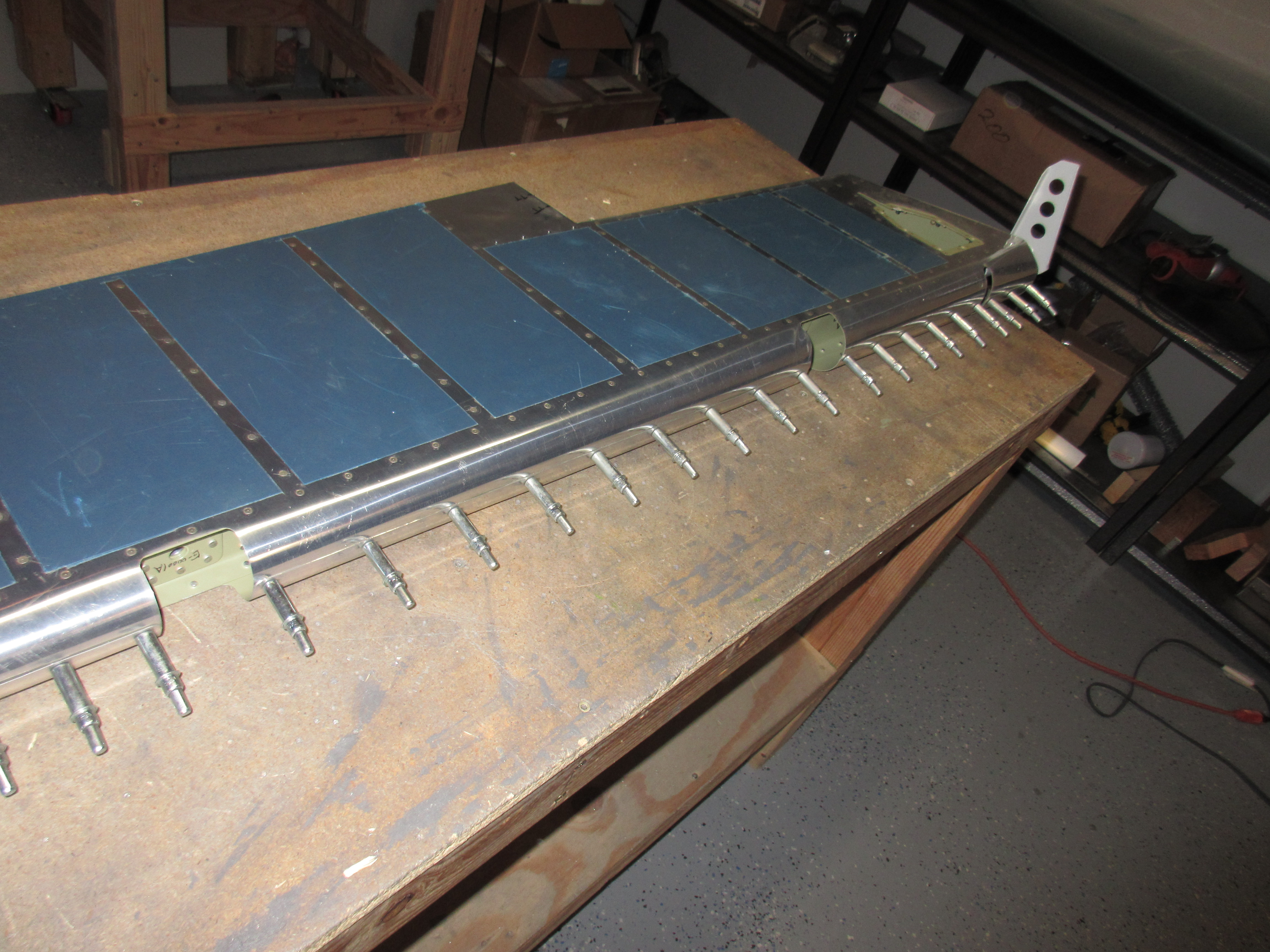
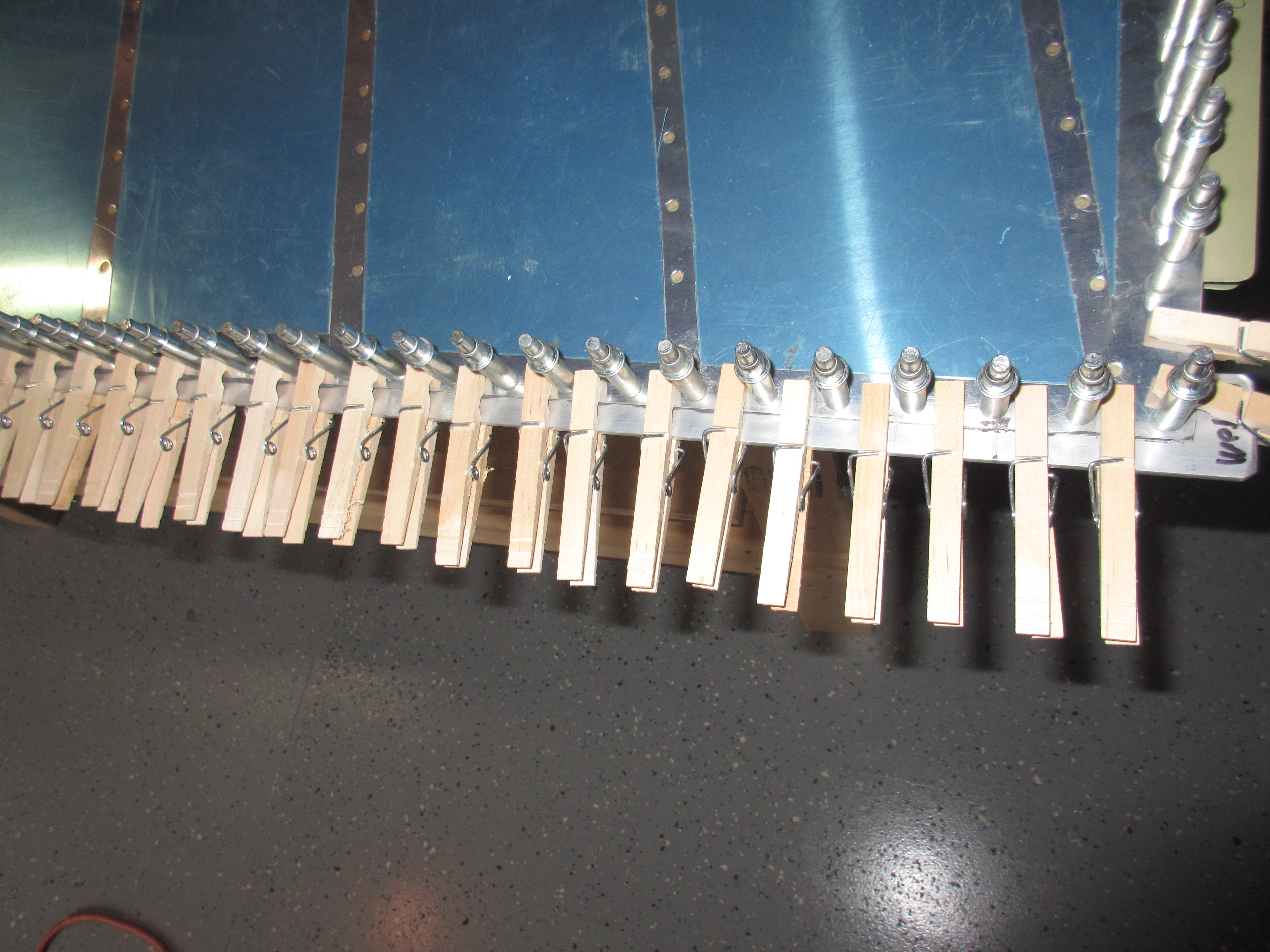
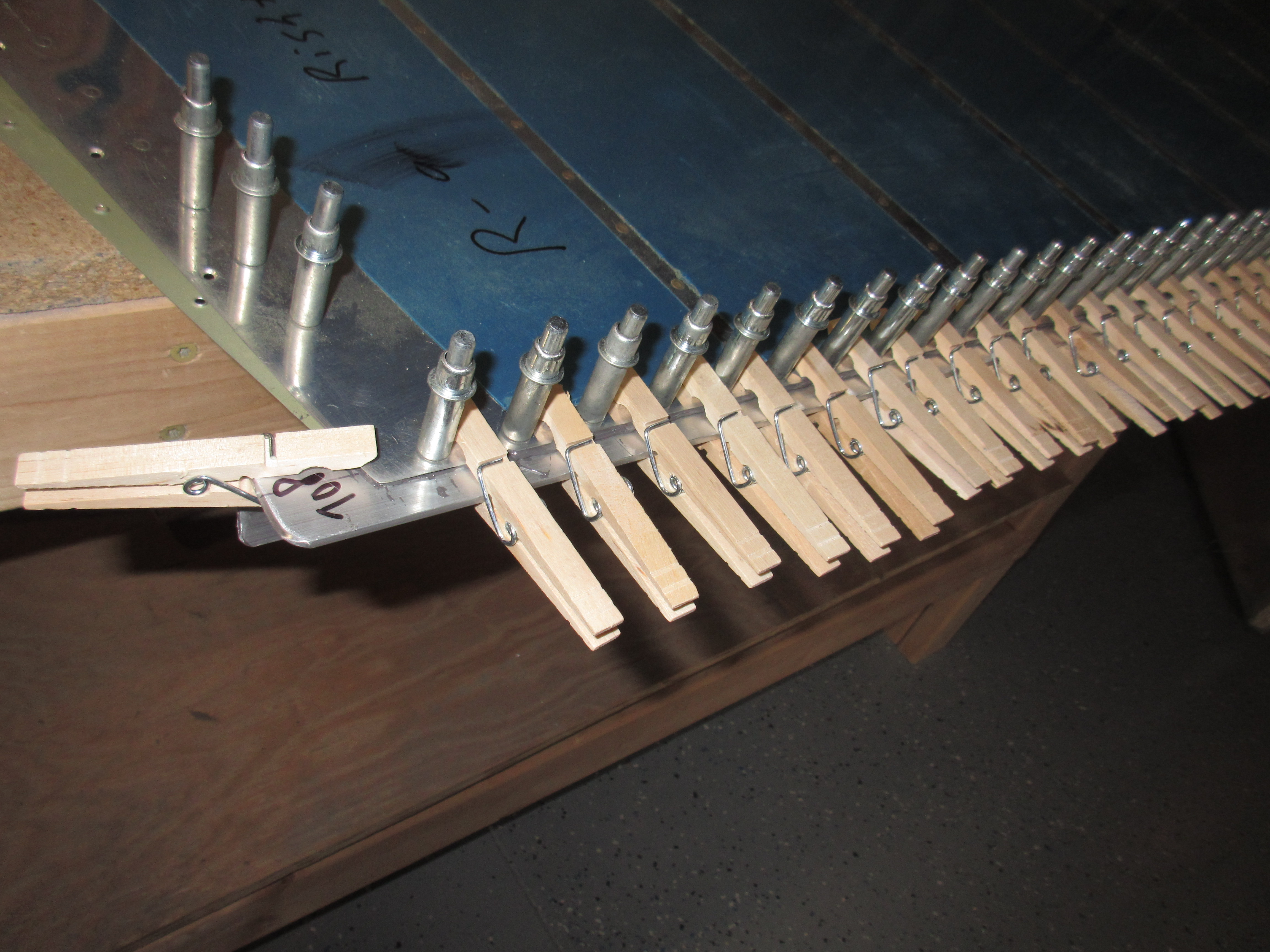
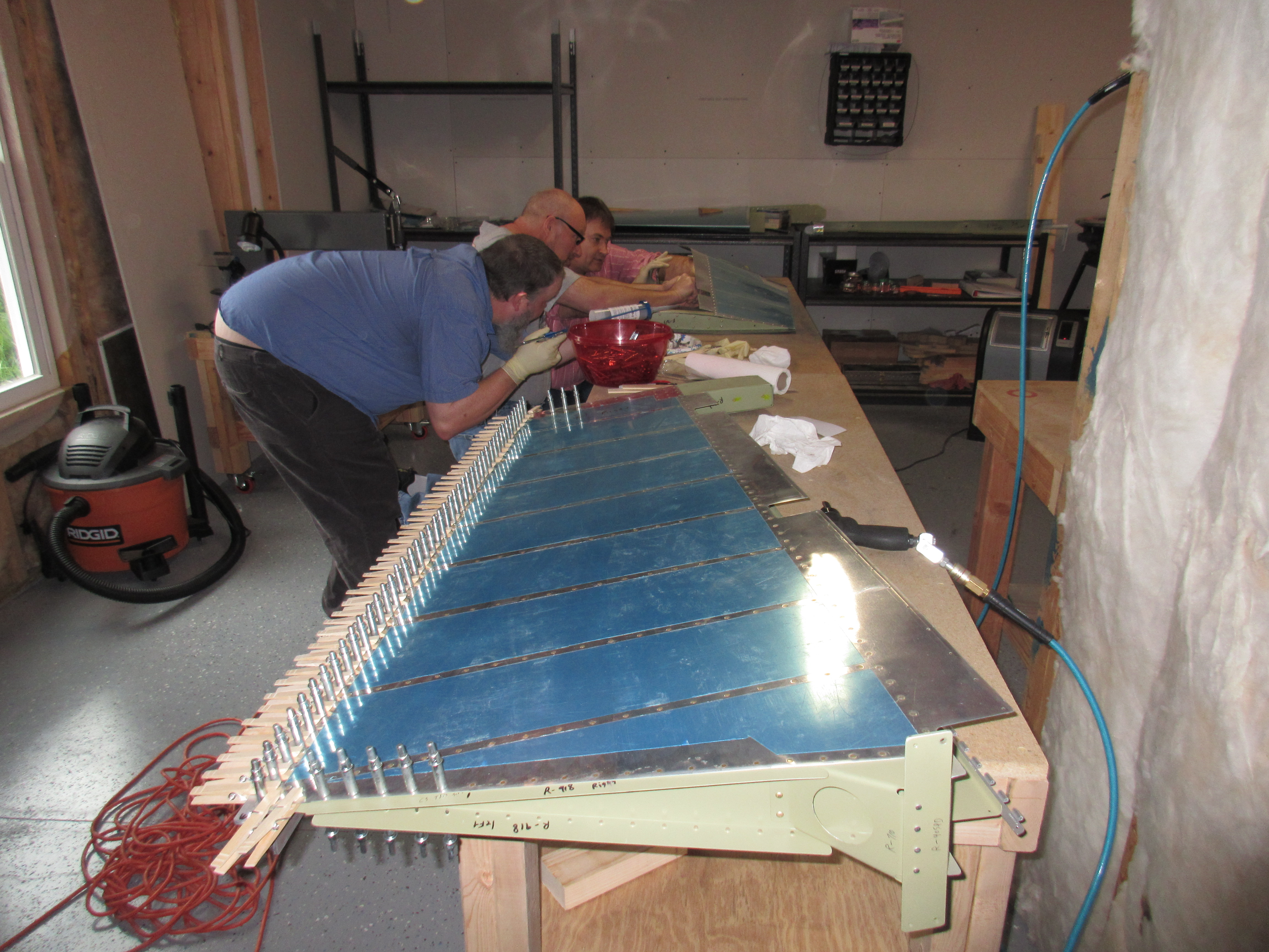
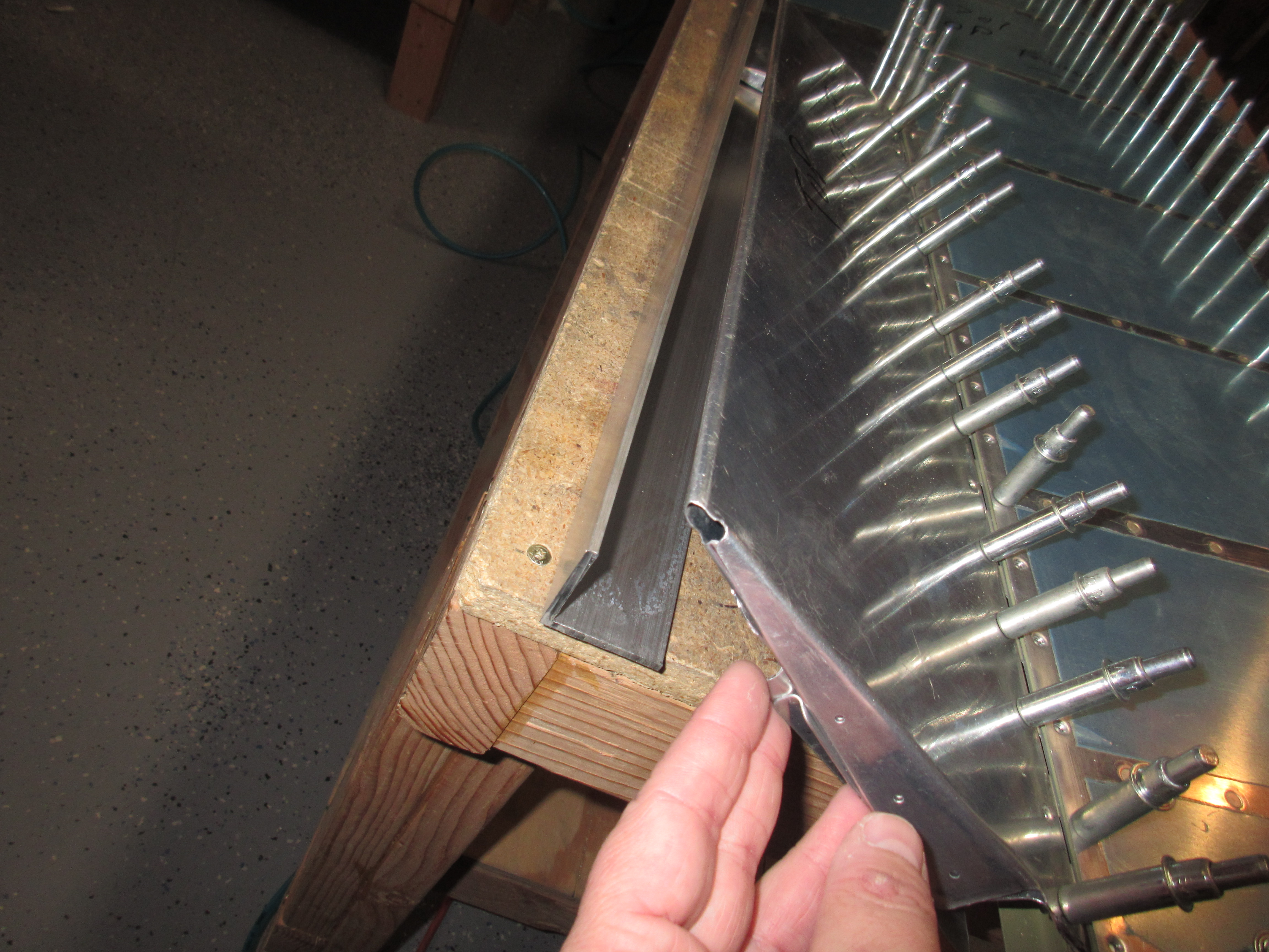
Just like the plans tells us, I flipped the rudder over and used my back rivet set on the tails of the rivets and the manufactured heads on the backing plate.  I have a longer backing plate so this made this part go really smooth.  I started out by half-setting all the number 1’s, then going back and doing the number 2’s and so on by working from the middle out on each sequence. Once I had them all half- way set, I flipped the rudder up to make sure the trailing edge was still perfectly straight….it was!!!

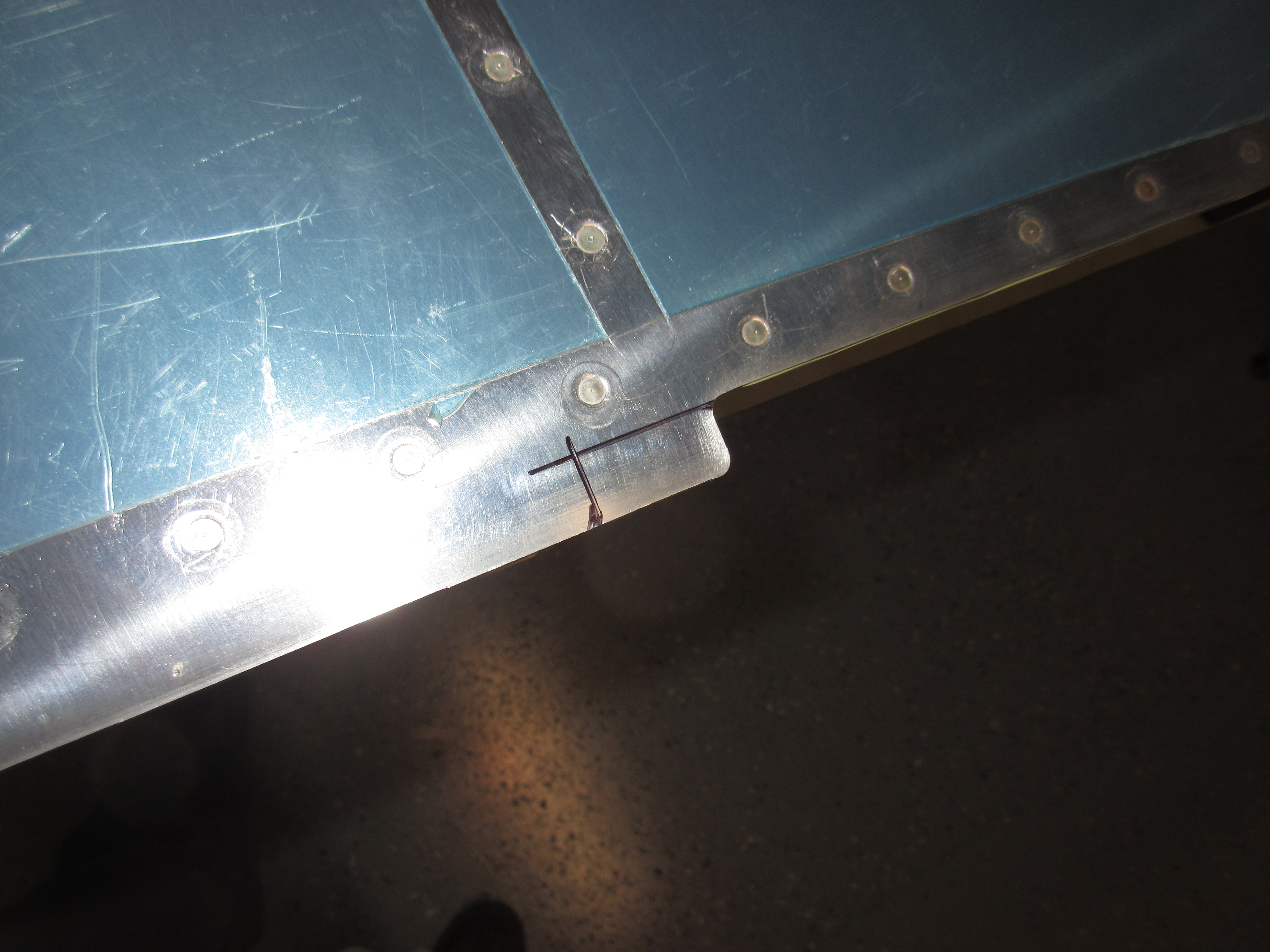
Now, I flipped the rudder over so that the tails of the rivets were facing the back rivet plate, and switched out the back rivet set on my rivet gun, for a mushroom style flush rivet set.  I used my same sequencing, and set the rivets fully by using the flush set against the manufactured head, and the tails were driven into the back rivet plate until they were nice and flush.  I only used the corner of my back rivet plate so that I could fit JUST the rivet I was working on against the plate, this would keep the other rivets from holding the trailing edge up away from the plate and causing it to bend.  It took a lot more fiddling to do this, but I think it made it turn out really straight.

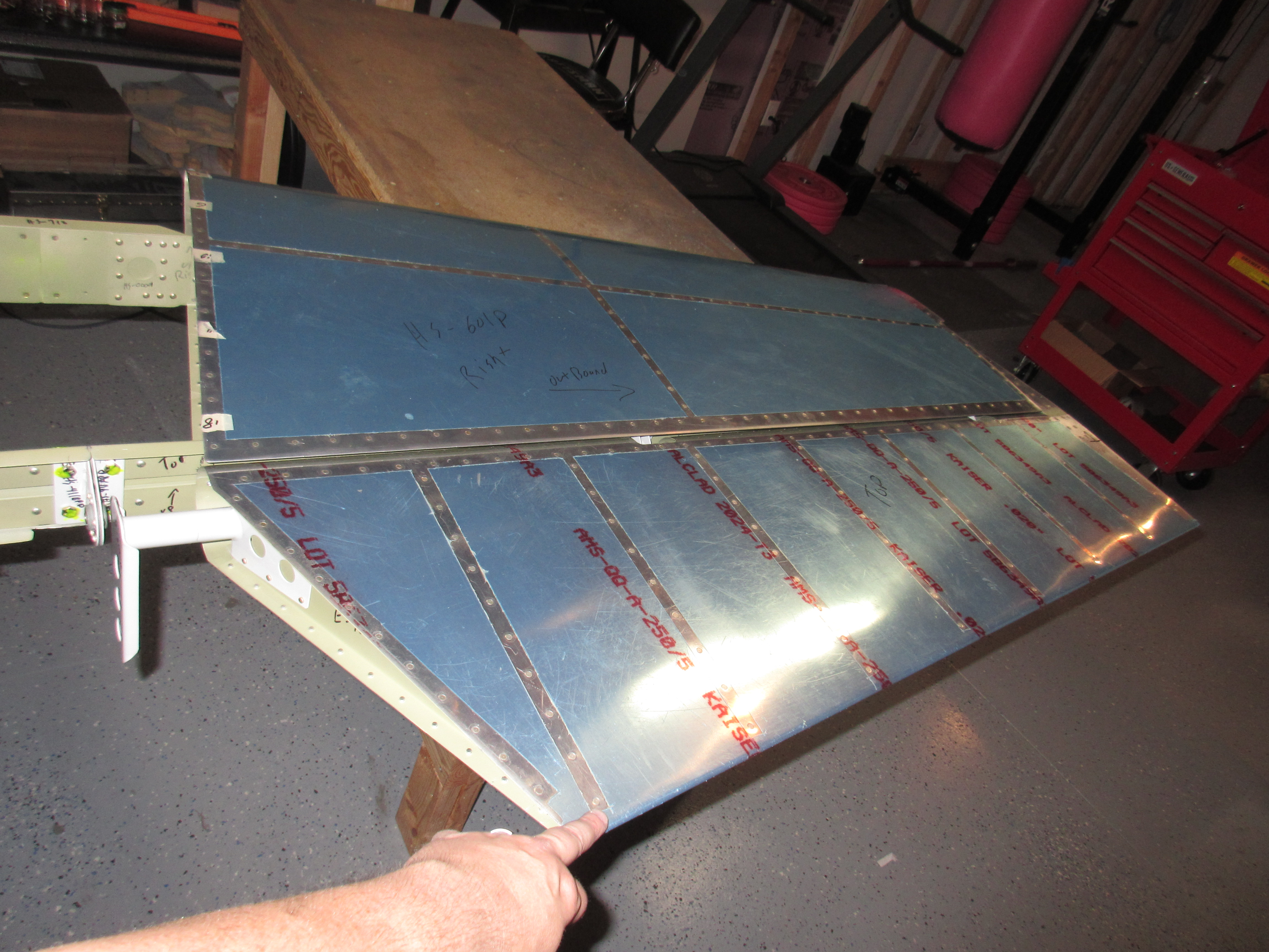
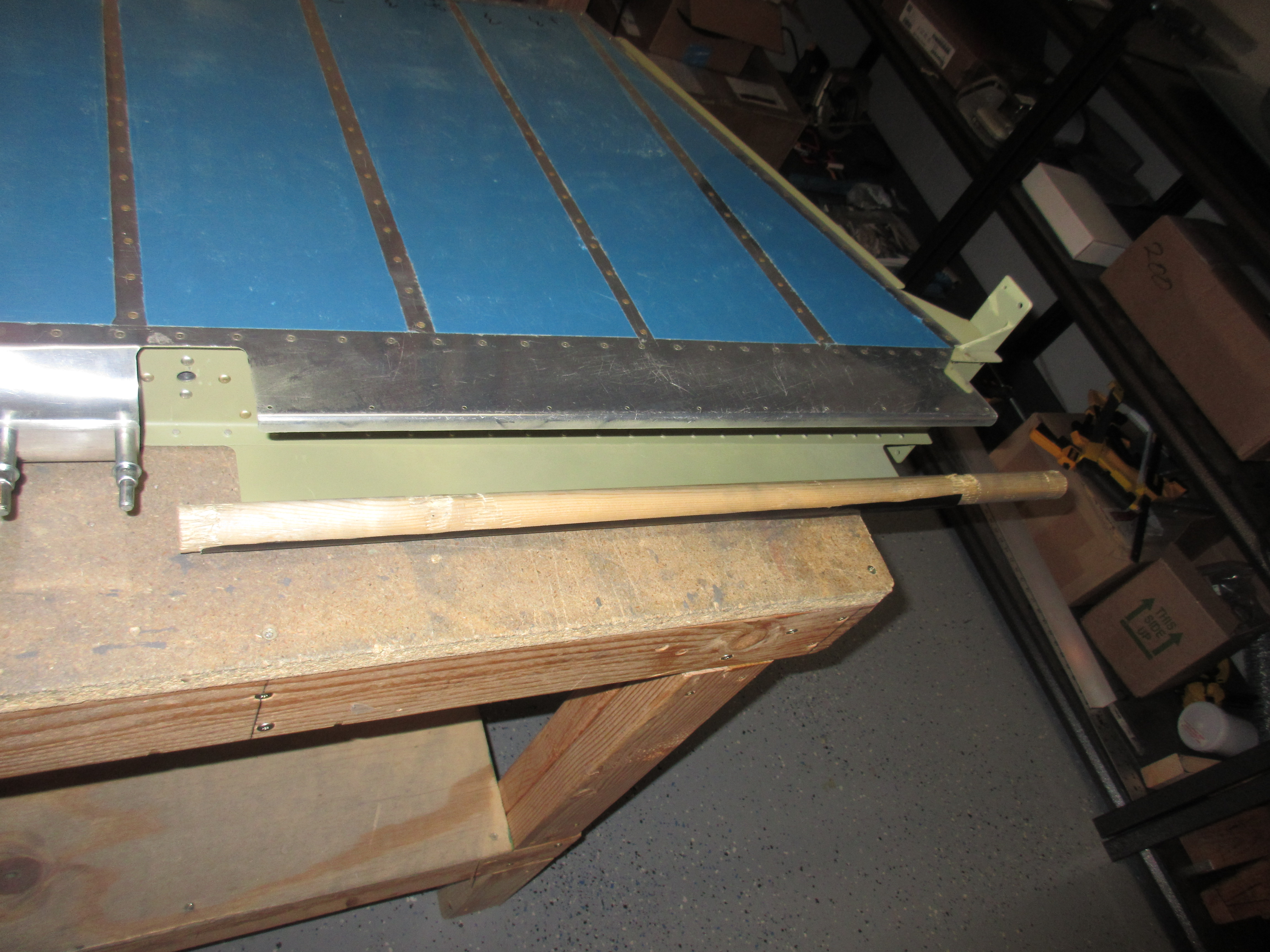
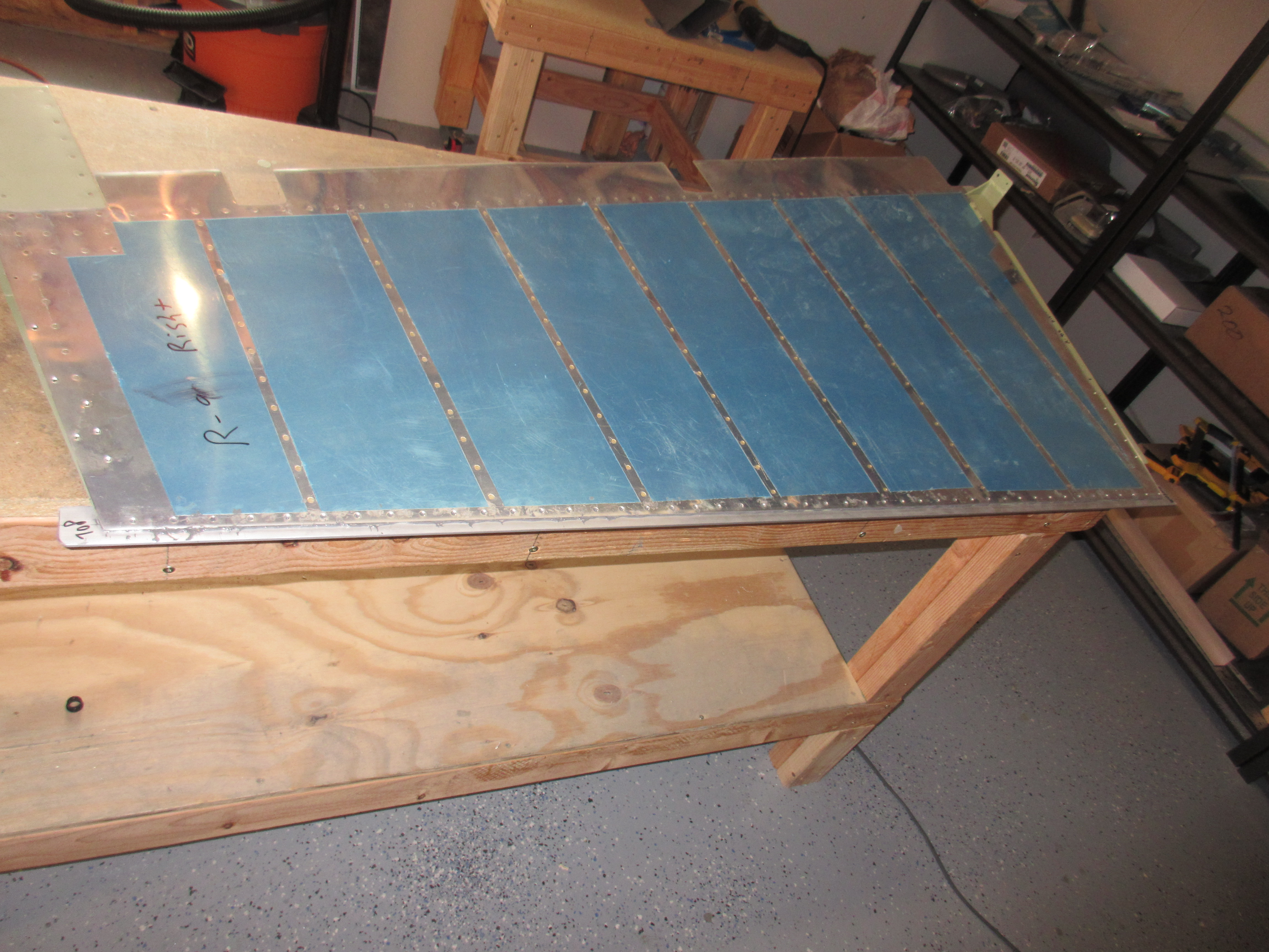
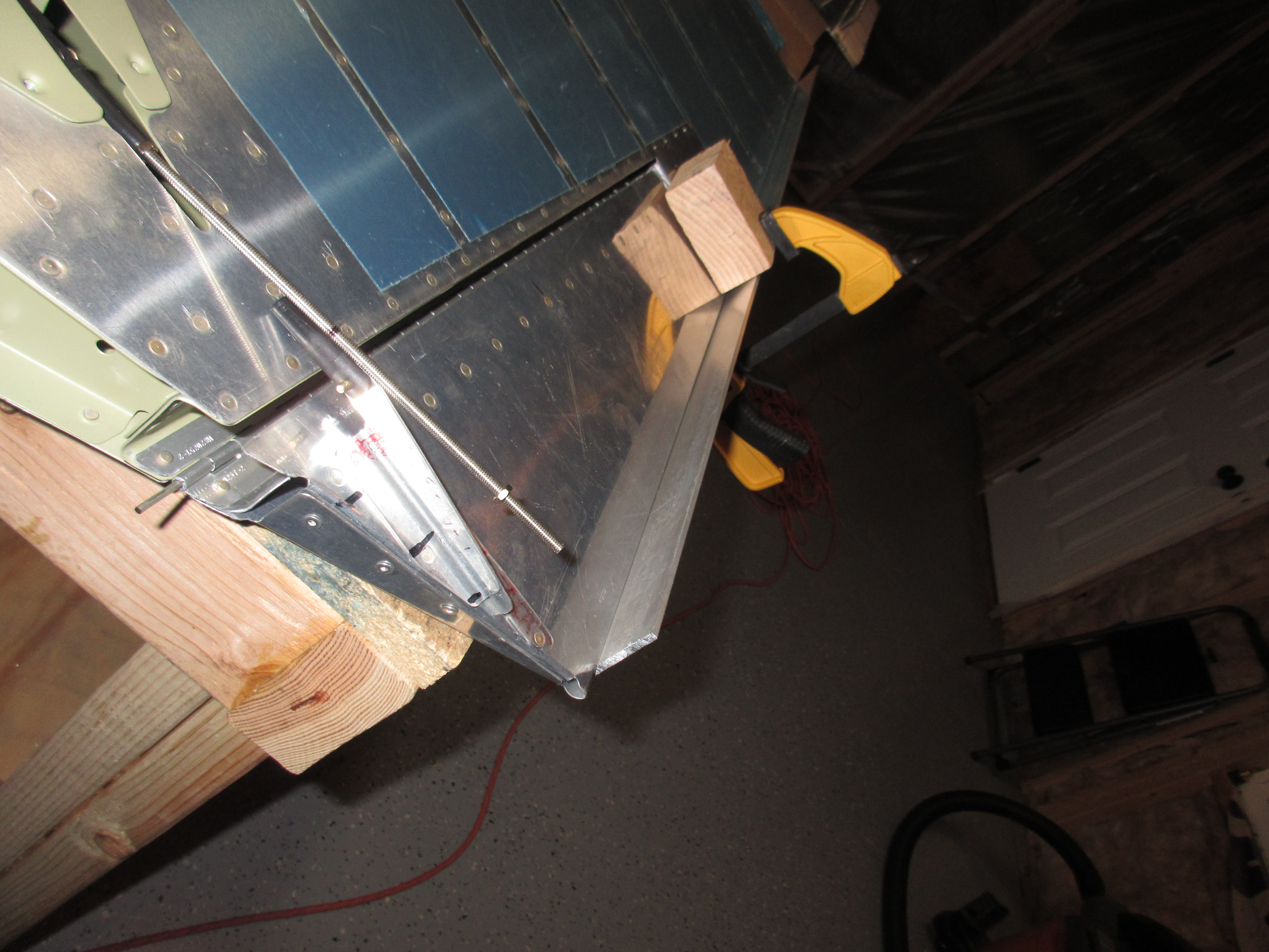
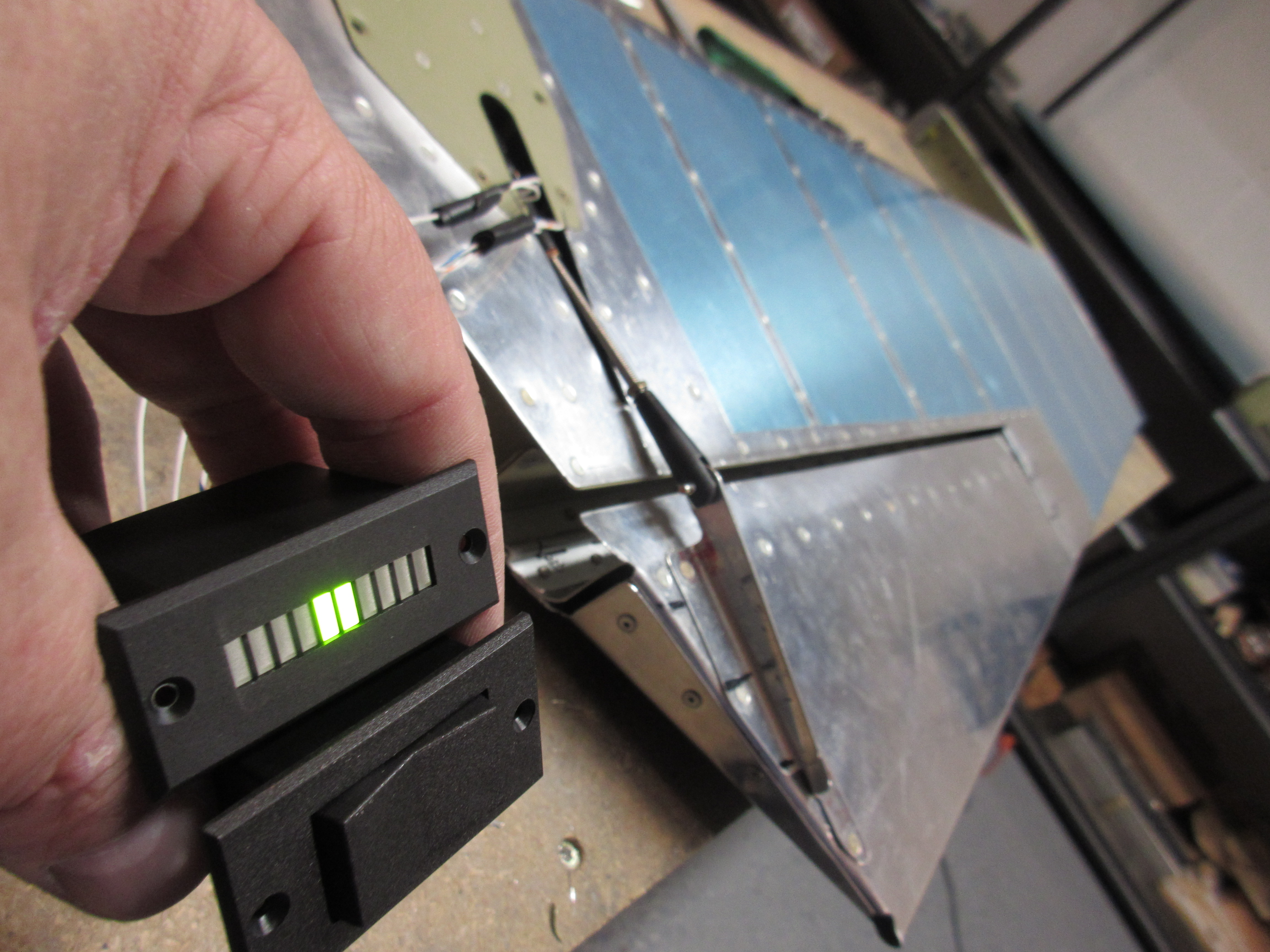
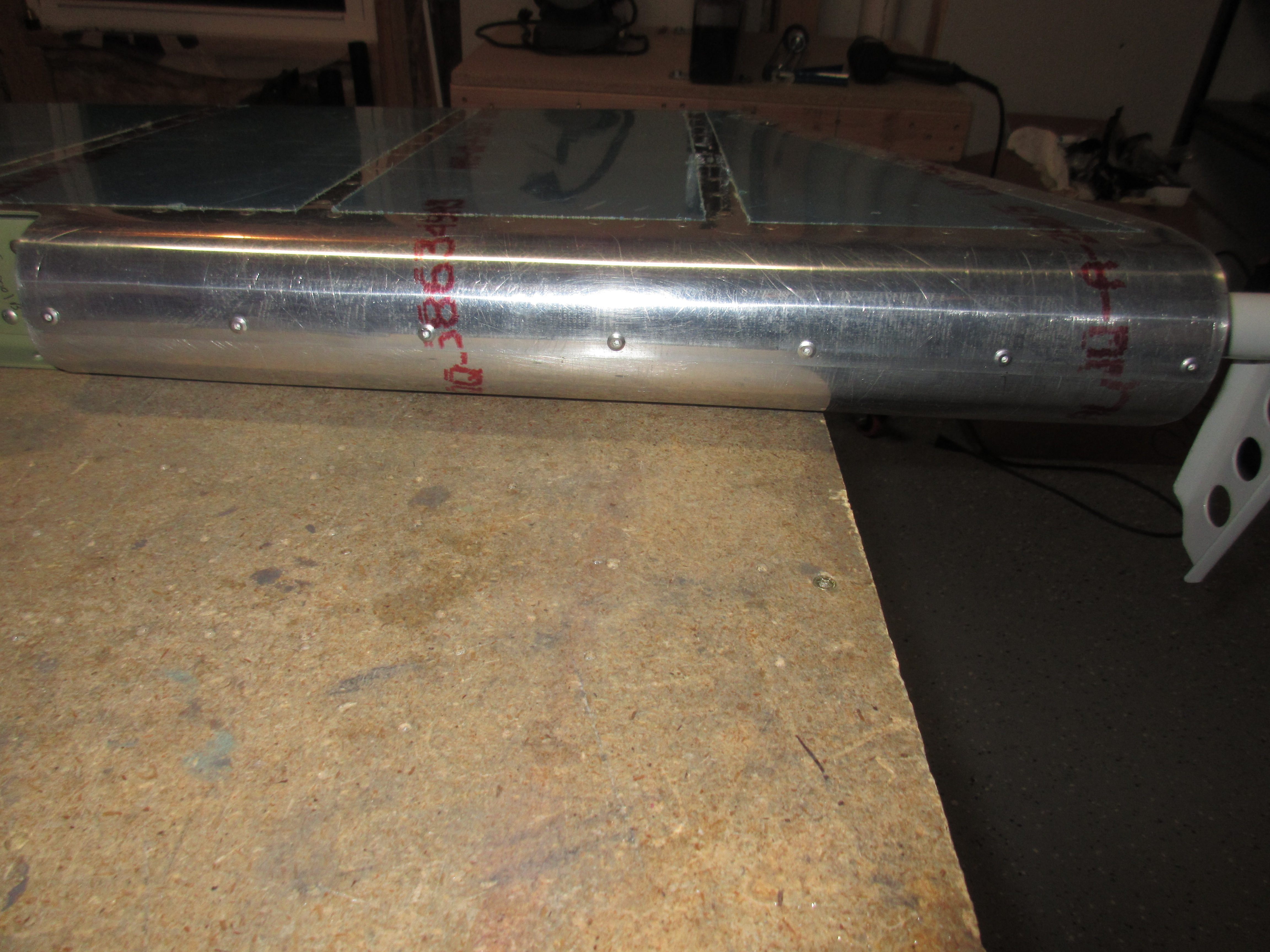
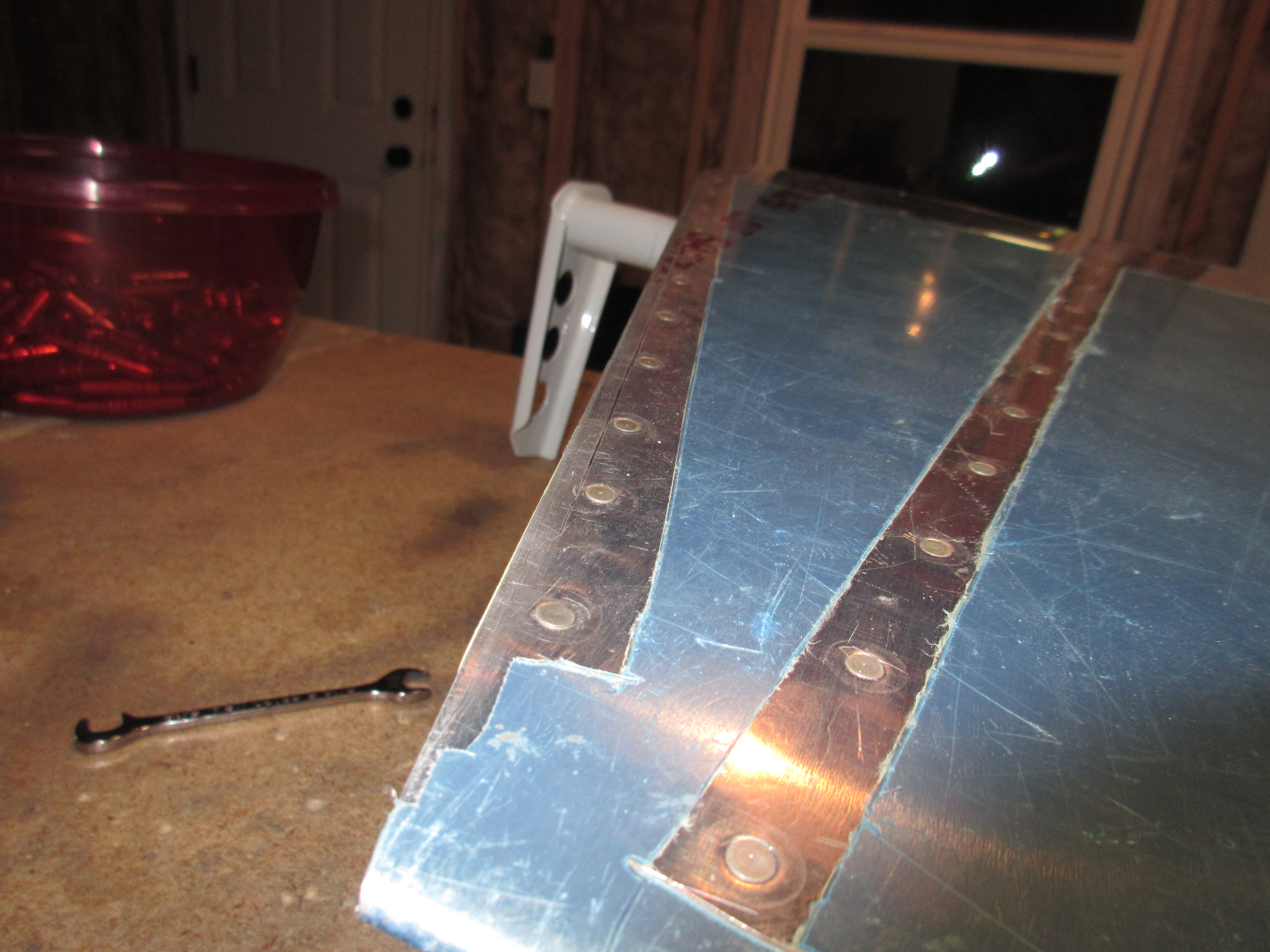
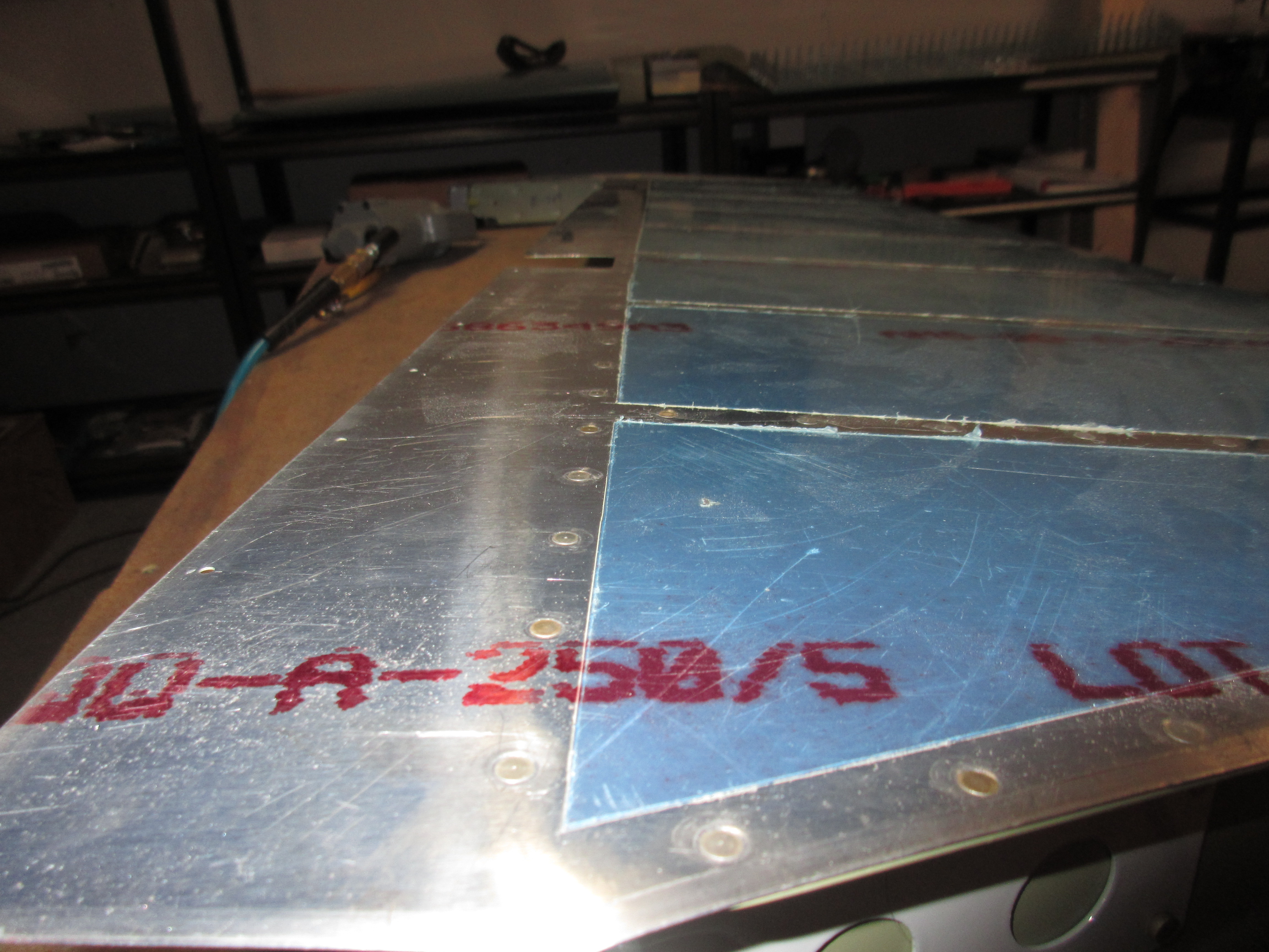
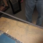
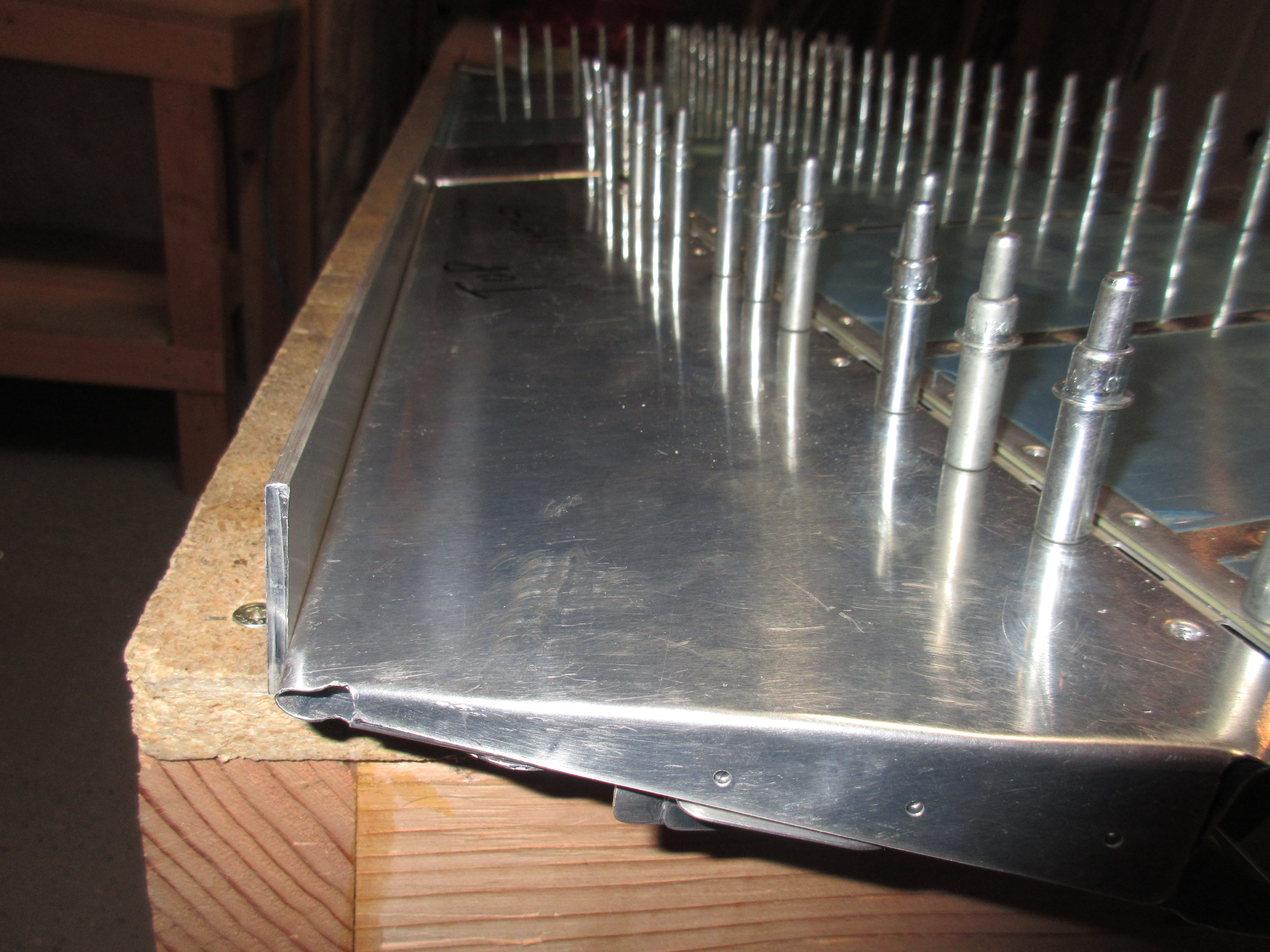
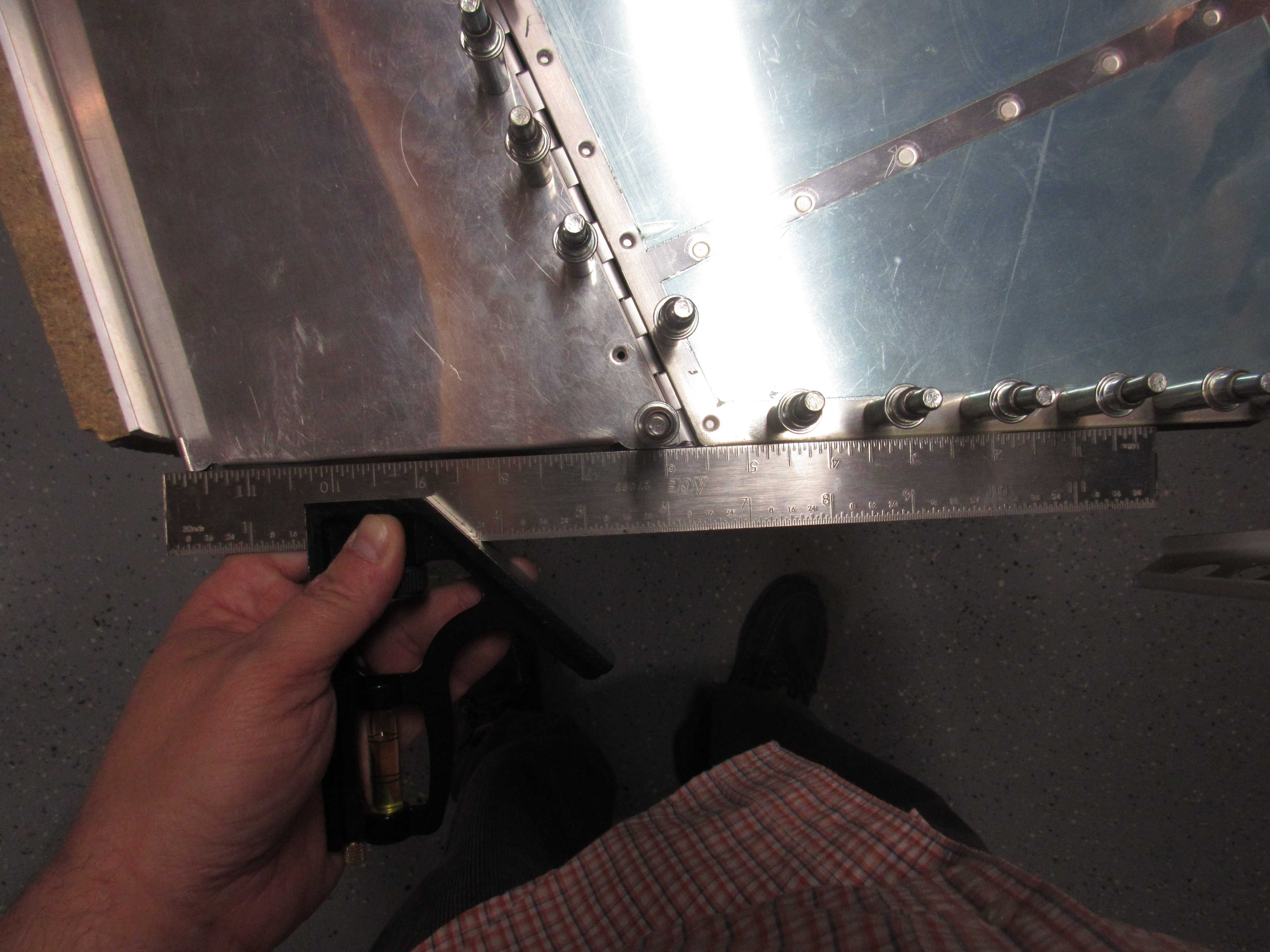
After I had worked my way out from the center of the rudder, using my riveting sequence, I turned the rudder up to make sure it was straight:

Yeah….I am definitely happy with that!! It’s not exactly perfectly straight, but it is WAY closer than the 0.100″ than Van’s says is tolerable.  I held the trailing edge against my aluminum angle to get a comparison, and to measure against my dial calipers, the worst I could measure was only about 0.05″ to o.075″ which is perfectly acceptable.

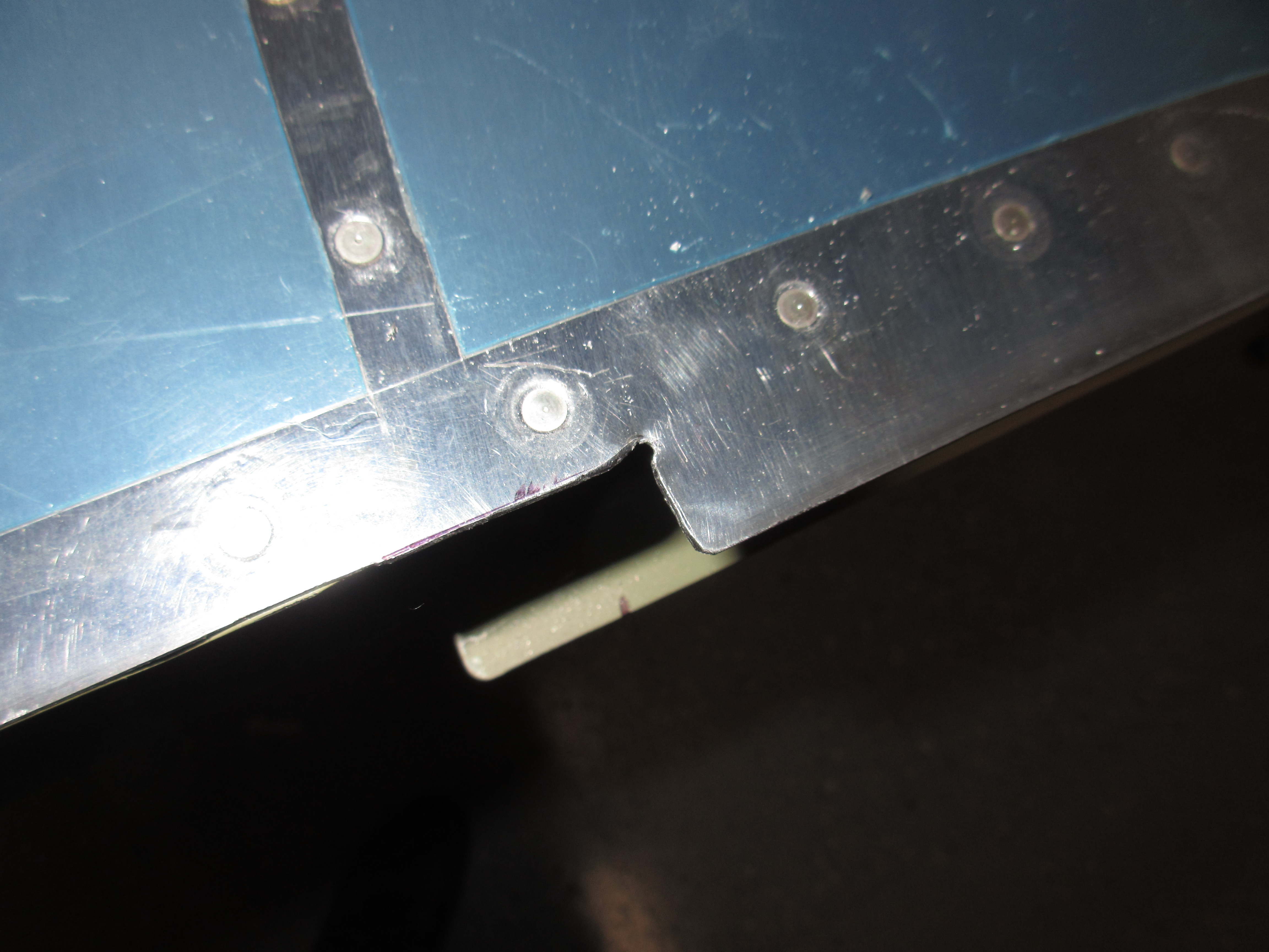
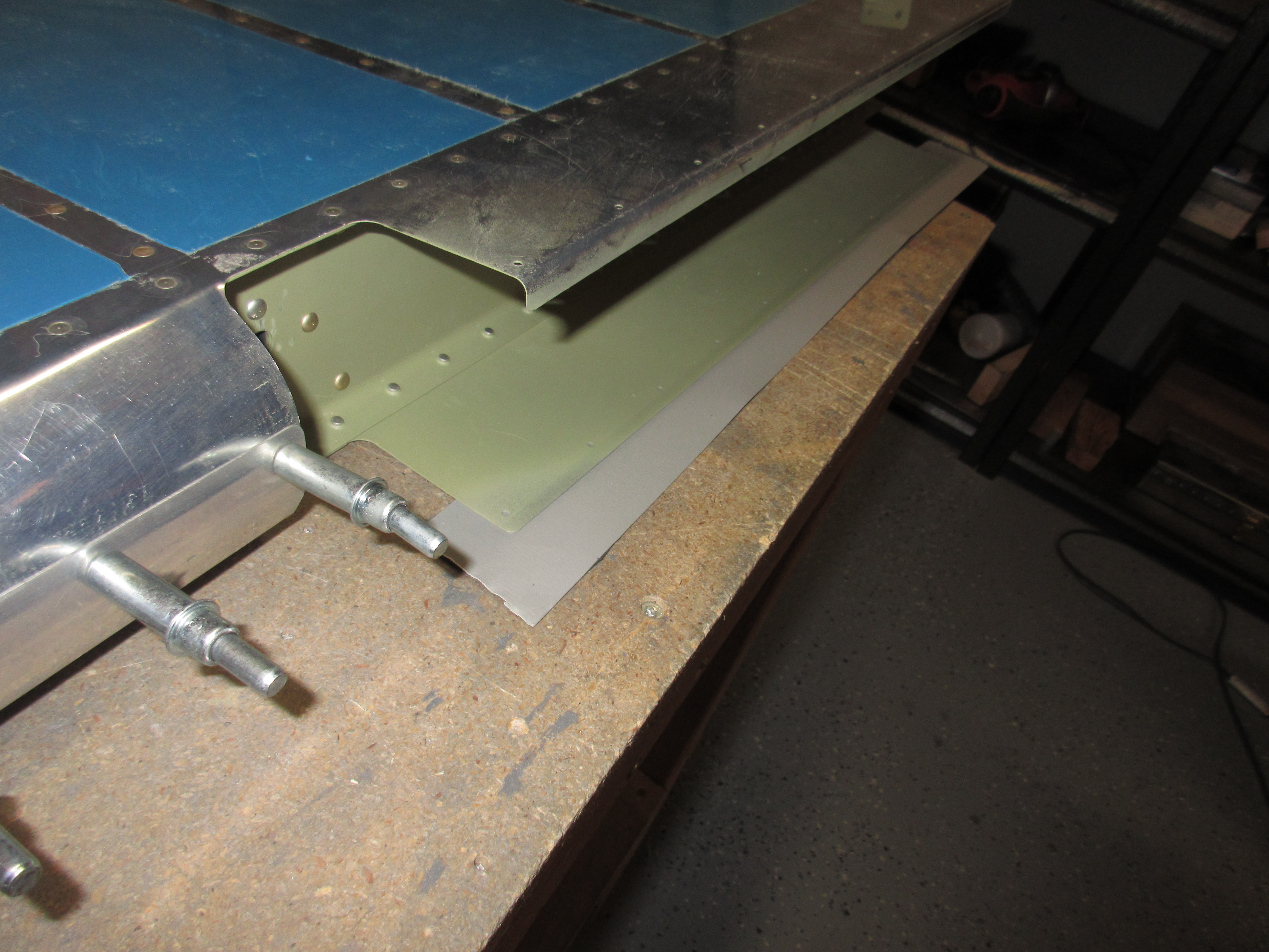
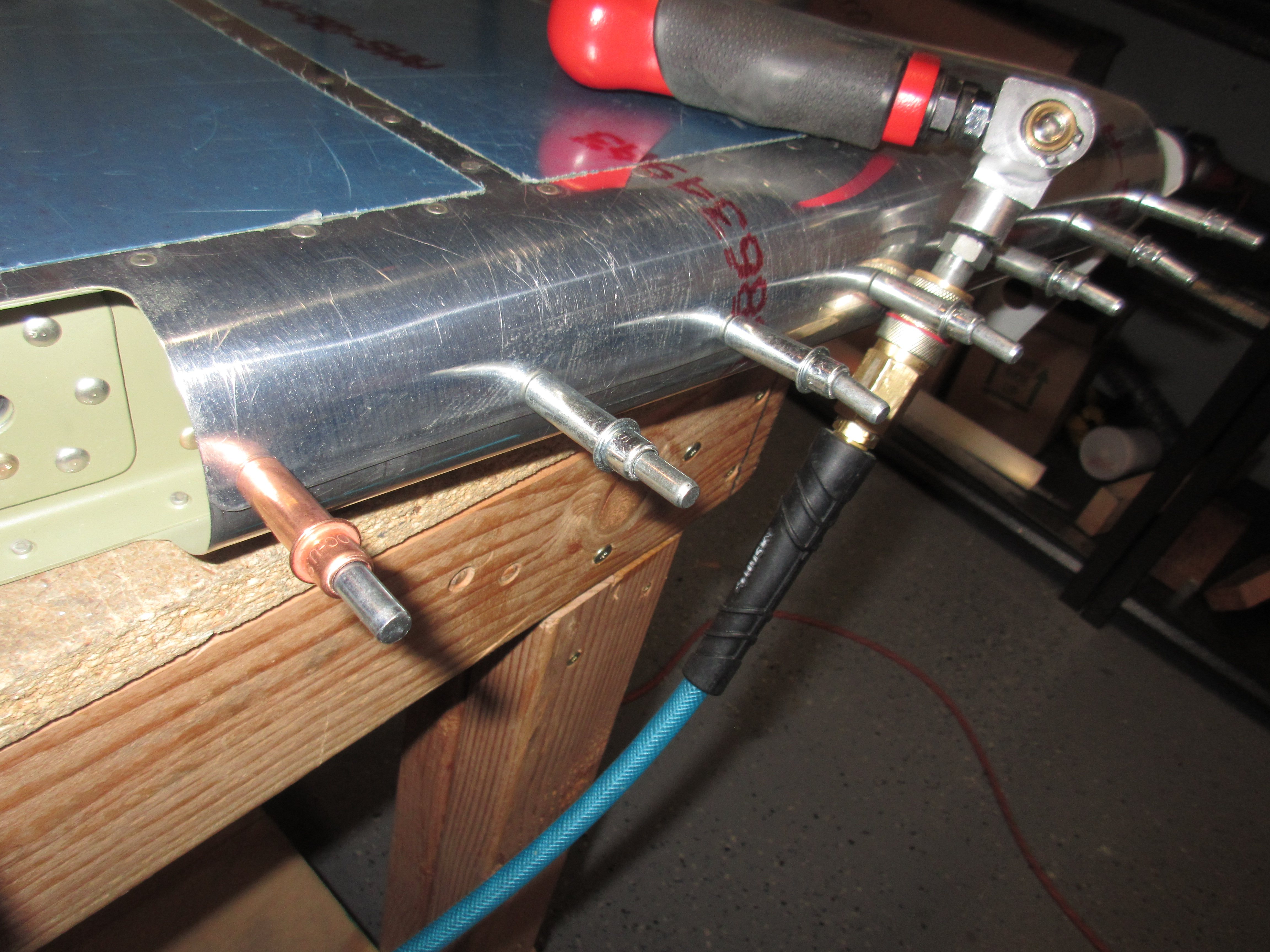
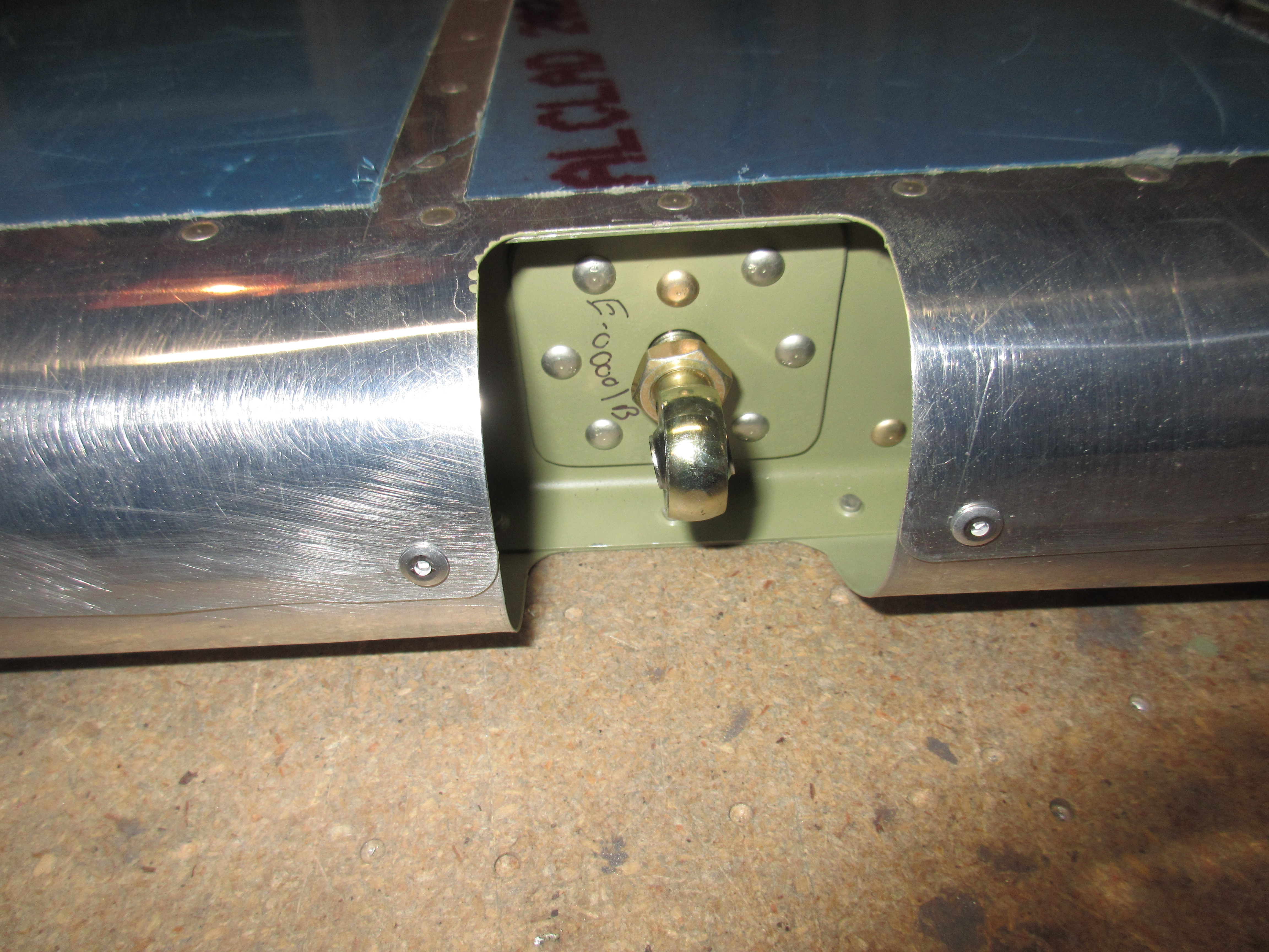
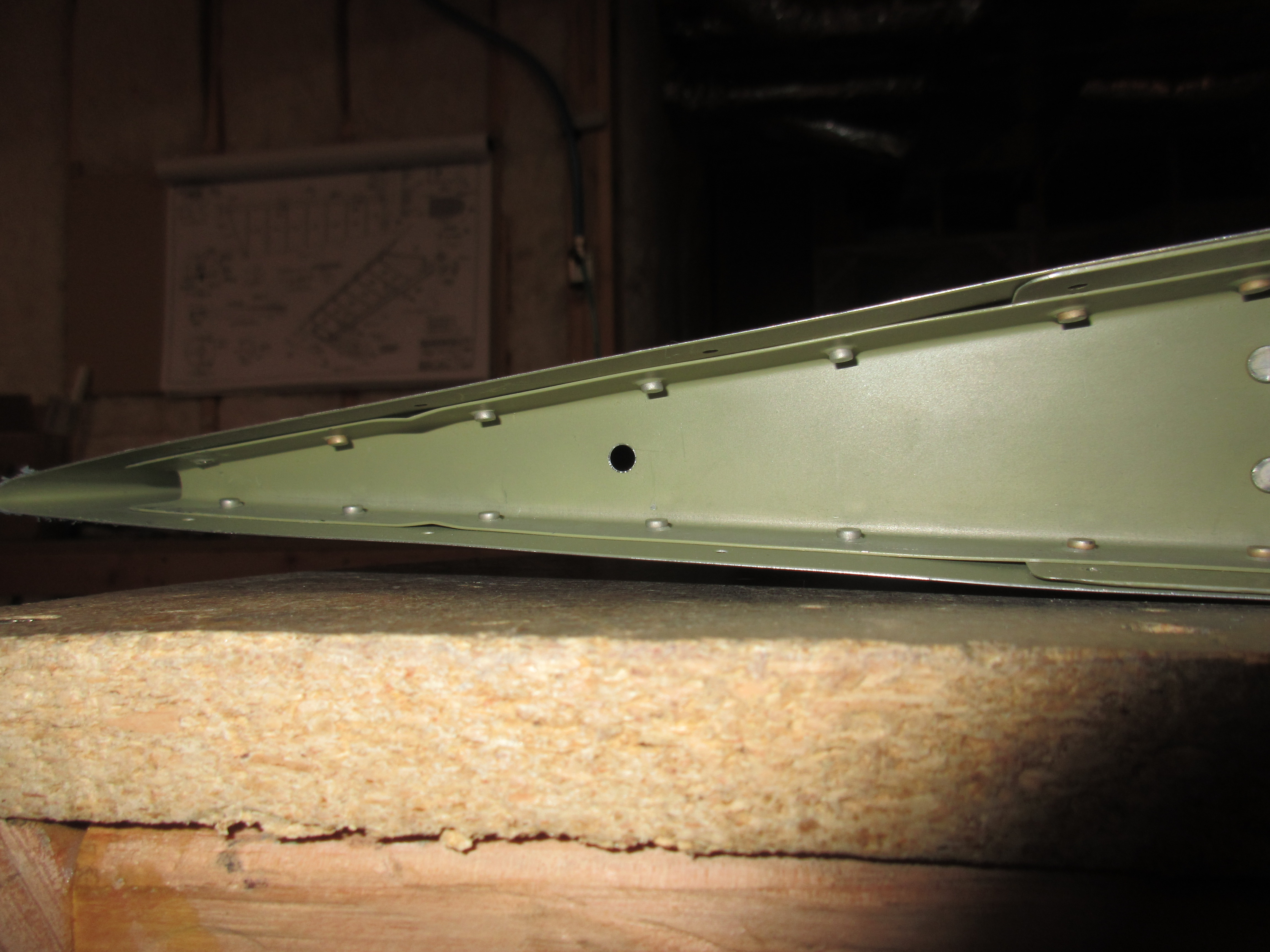
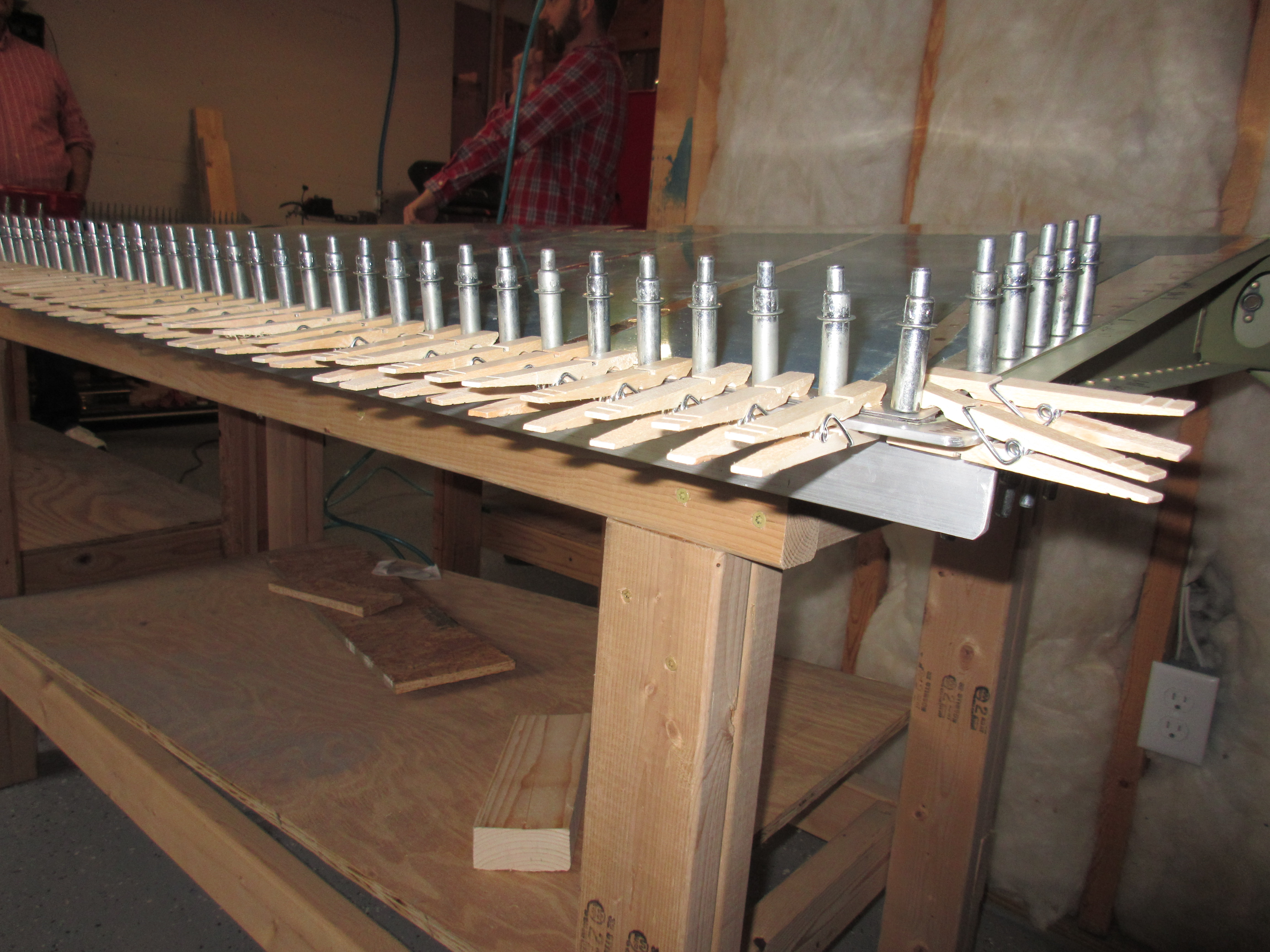
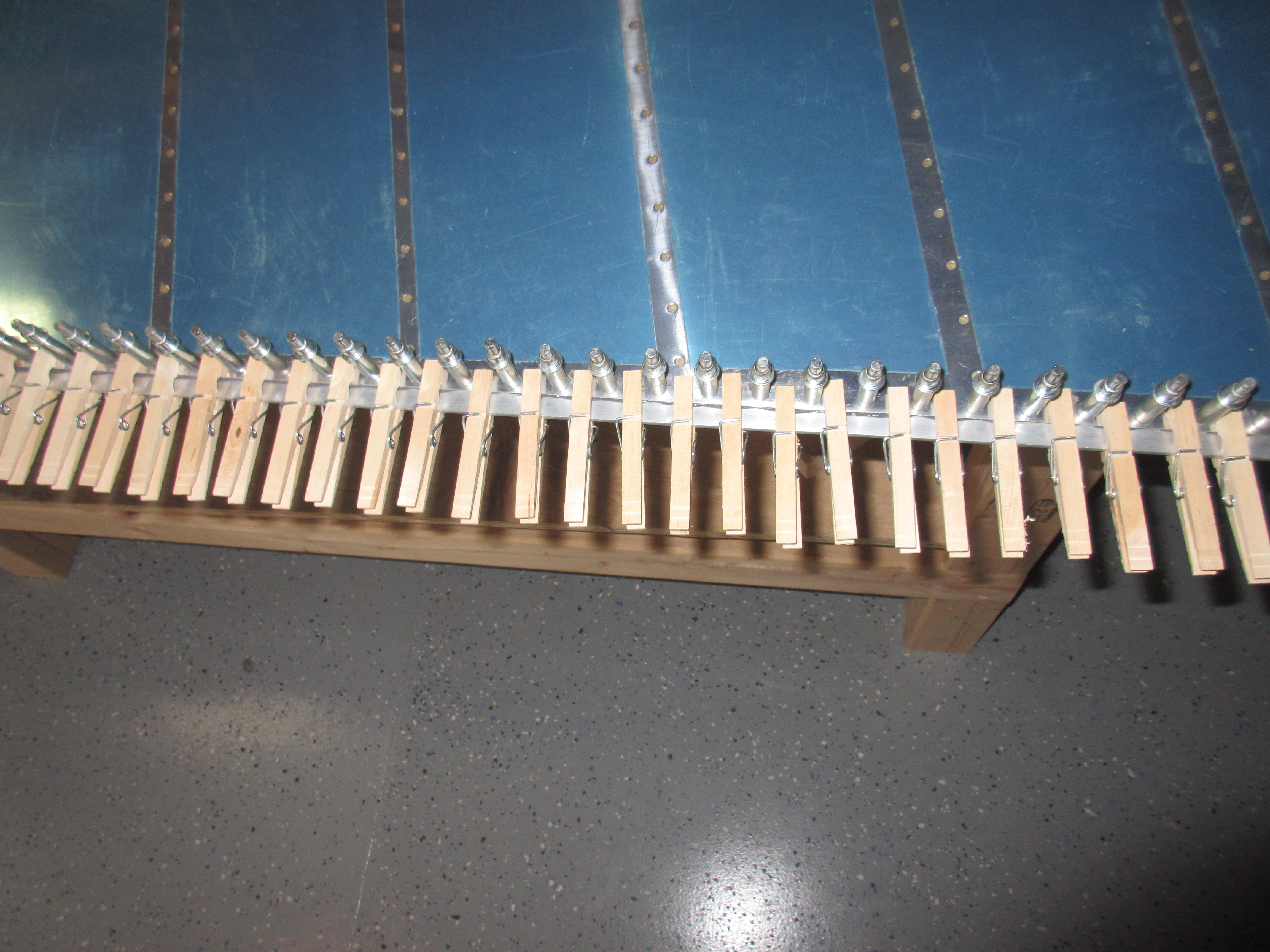
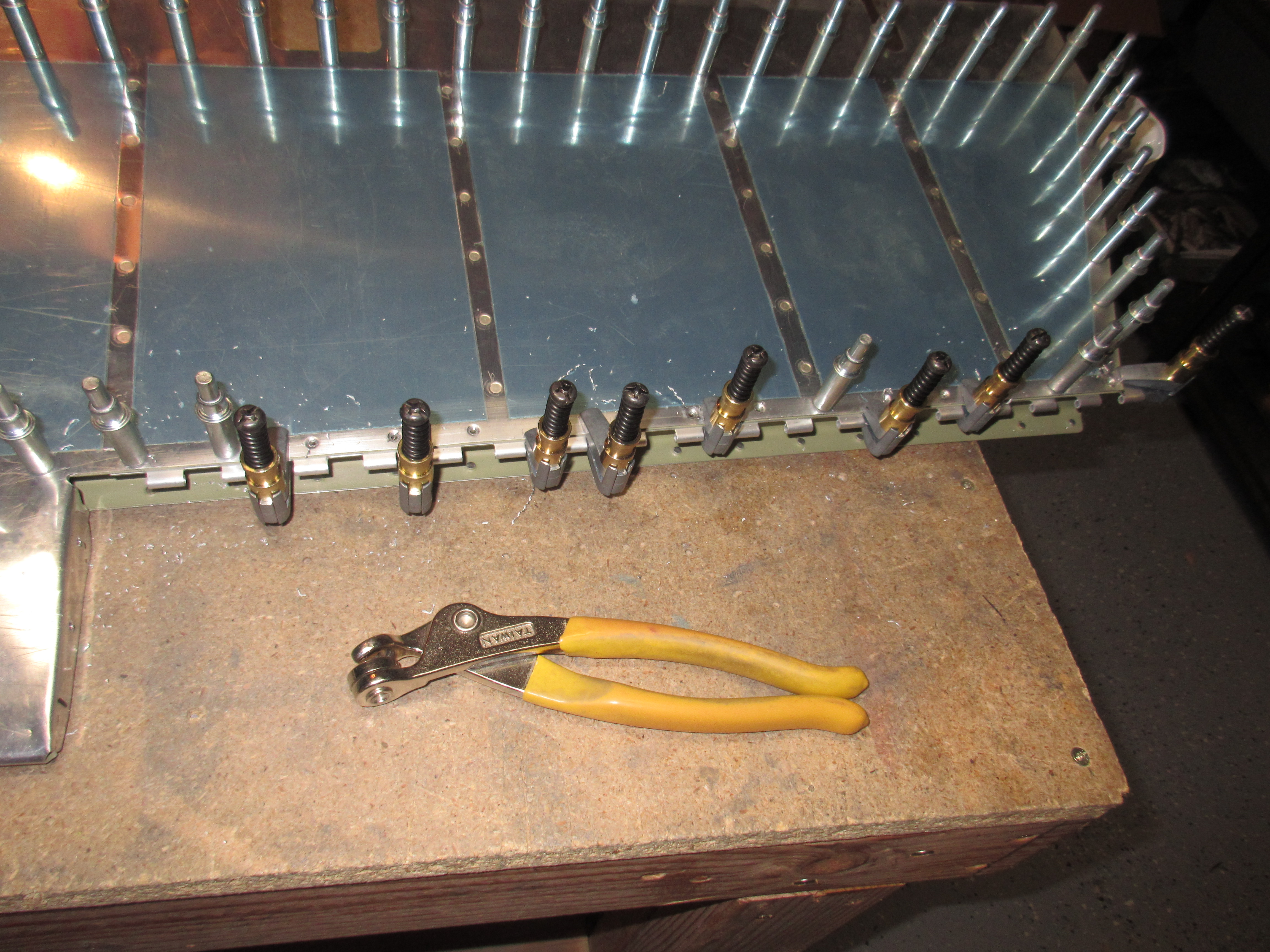
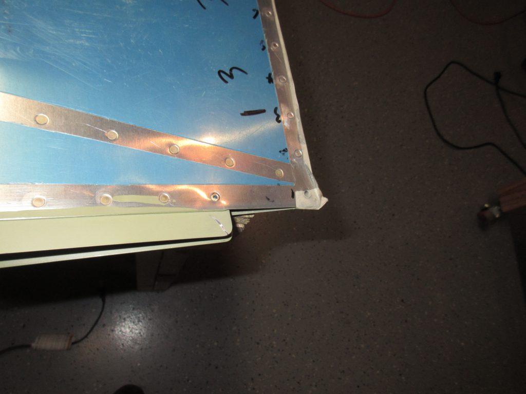
Once I had the trailing edge done, I had a few more rivets to squeeze on the top and bottom ribs.  I had left these out to make it easier to apply the pro-seal, so its time to set those babies.  I was able to use my squeezer on all of them except the very last one closest to the trailing edge.  Vans’ says its fine to use a MK-319-BS blind rivet in these last holes because of the super tight clearances.  I decided that’d be the route I’d go, because I did NOT want to mess up this beautiful rudder with trying to squeeze or rivet that very end rivet!  So, I stuck in a MK-319-BS blind rivet, and carefully set it using a pop rivet tool.  They came out really nice, and are almost perfectly flush with the skins. When she’s painted, this will get a little bit of filler and you’ll never know it 🙂

The rudder is now 100% riveted together!  All that was left was to clean up the edges of the trailing edge with some scotchbrite pads to break the edges, as well as to knock off any squished out pro-seal.  Then I rounded off the corners of the trailing edge using a file and scotchrbite pads.  That’s it for tonight! I am happy to have this part behind me now.  I have been dreading it for a while, but it actually wasn’t to bad to do.  I set aside a day when I’d have plenty of tie to concentrate and get it done slowly and correctly. This rudder will fly straight as an arrow!

This slideshow requires JavaScript.

Google photos Link: https://goo.gl/photos/auZhkD8hAYvLhdiH8

Hours Worked: 2.5

Mounting the Trim Tab Servo

Since my rudder trailing edge is still curing, I decided to work on the last remaining task left on the empennage: Mounting the trim tab servo.  I started out the work tonight by wiring up the servo, its indicator and switch to my 12V bench power supply to test its function and make sure it was in the neutral / take-off position.   I have a pretty good background with low voltage and electronics, so this was pretty fun for me.  After a little fiddling, I managed to get the servo working, and the indicator showing its true position.  I made sure it was in the neutral spot before un-wiring the servo to install it in the elevator. Here’s a video of it on the bench.

I mounted the servo to it brackets on the E-616-PP plate, and then inserted it in the left elevator so that I could cut the jack screw to the proper length.  The kit ships with a 7″ jack screw, which is WAY longer than you need.  I made sure my trim tab was in complete alignment and in trail with the elevator by using a long peice of angle stock, a block of wood and a small clamp with very light pressure.

Now that the trim tab was lined up in the take-off / neutral position, it matched the position of the trim tab servo.  You can see in the photo above just how long the jack screw is.  I used a ruler to measure from the middle of the clevis pin attachments on both the trim tab and the servo and came up with just about 3.5″ inches in length.  I used a hacksaw with a metal cutting blade, and a clamped the jack screw to my bench and made the cut.

After I cleaned up the threads on the cut end, I threaded the jack screw into the clevis pin attachments and adjusted the length so that it aligned perfectly.  Now I have my measurement, I use the jam nuts to lock the clevis pin attachments into place so I could continue working.  I then re-wired the servo so I could move it across its entire range and mark where  I needed to trim the skin.  Van’s mentions in the plans, that its OK to trim the elevator skin to allow for proper clearance of the jack screw.  I had to trim a decent amount to keep the jack screw from contacting.  I used a combination of tin snips, files and scotchbrite pads to get it roughed into shape.

Once I had the skin trimmed to where I wanted it, I ran the servo through its entire range of motion to check for binding and clearance.  I also checked the maximum angle of deflection using a protractor and angle finder and I have right about 25 degrees of up and down max deflection.  This is right at the lower bounds of what Van’s recommends for the maximums (25 – 35 degrees).   I left plenty of room for adjustment in the jack screw, but I am not sure if I have any room due to clearances if I need more travel.  I honestly think since I am at the lower end of the maximum range, I will be fine. This is a very big trim tab, and 25 degrees is a sizable deflection.  The important part was that when the indicator is indicating neutral / take-off position, the trim tab should be completely in trail and aligned with the rest of the elevator.  My trim tab hit this perfectly:

With the skin trimmed out, and the servo able to move through its range with no binding, all that was left is to clean up the edges.  I used a file to smooth all my cuts, round out the corners, and followed it all up with a good buffing with a scotchbrite pad and then vacuumed all the shavings out.  I removed the servo and stored it in its box, and I also took the trim tab off the elevator.  I am planning to store these separate to avoid them getting damaged. I think I might end up making some sort of shelves or hangers in the rafters of my basement/shop to keep my empennage parts up and out of the way.  That finished up tonights work session.  Roughly 3 hours spent total, most of that was trimming the skin and finishing those edges.  Here is the full photo album:

This slideshow requires JavaScript.

Google Photos Link: https://goo.gl/photos/VQUi3zfEgV4Lebcp6

Hours Worked: 3

Bending the Left Elevator Leading Edge

After getting the right elevator bent,  it was time to move on the left.  This process is pretty much identical to the right elevator, so I will leave out all the details.  I did it exactly this one the same way as I did the right.  First up is to break the edges of the top skin to help the lap joint form a nice tight lap.  I used my edge breaking tool to do this.  Then, starting out by bending the top skin leading edge, I used a dowel rod and gorilla tape to roll it to the right bend, and then finished it off with my hands.  I did the same with the bottom skin.   Once all the bends were made, I clecoed them together.

The next step is to match drill all the holes to a #30 hole for the AD-41-ABS blind rivets. I did one hole at a time, and replaced it with a 1/8 inch cleco as I went. Once all the holes were drilled to the proper size, I unclecoed everything and deburred the holes with a scotchbrite pad.  Then, re-assembled everything back with the clecos to hold them in place while I set the blind rivets. I worked my way down the leading edges, removing a cleco and setting a blind rivet as I went.  Eventually, it was all riveted together and looking good:

The last step for the night was to install the AN316-6 jam nut onto the  MD3614M rod end bearing, and then insert that into the plate nuts on the spar.  I used Boelube on the threads to make this a bit easier, because platenuts can be hard to thread into.  I don’t have my rod end bearing tool made yet to thread these all the way in, nor do I have a caliper to measure the distance, so I just threaded them in a few turns and I will come back and get them set to the proper depth when I have those tools.  I need to do this to the right elevator as well.  Here’s the photos from tonights work:

This slideshow requires JavaScript.

Google Photos Link: https://goo.gl/photos/Krv1f4cjMnk98k5NA

Hours Worked: 1.25

Bending Right Elevator Leading Edge

With the right elevator all closed up, one of the last remaining steps is to bend the leading edge.  This is a bit tricky to do, and I am using the tried and true method of using a wood dowel rod and some strong Gorilla Tape to get the bend just right. I started off tonights build by first breaking the top edges of the leading edge using an edge break roller tool.  This little tool has two rollers welded to the end of a pair of vise grips. You insert the skin edge and gently pull it along the edge, creating a slight bend / break along the edge.  This allows the lap joint between the top and bottom skins to fit snug together once they are riveted.

Then, I began by bending the smaller section of leading edge on the outboard side.  I bent the bottom first, and then the top by securing a large section of gorilla tape to the leading edge, and wrapping it around a dowel rod.  Then I used some channel locks to slowly rotate the dowel rod and curled the leading edge ever so gently to get the bend angle.  Once I had the top skin done, I done the bottom skin.  Then it was time to get a bit physical with the metal, and form the remainder of the shape with my hands by brute force and squeezing.  Eventually, I had the leading edge of the smaller section where I like it, and clecoed it together.

I moved on to the remaining sections of leading edge, but this time  I decided to bend the top section first, followed by the bottom section.  This seemed to make the lap joint much tighter and more rounded.  Once I had all the bends done, I clecoed everything in place.  The plans has us drill the #40 holes to a #30 in order to fit the AD-41-ABS blind rivets, so I removed one cleco at a time and drilled to proper size, replacing it with a 1/8 cleco.

Finally, I had all the bends where I wanted them, and the holes properly sized, I used my pop rivet tool to set all of the AD-41-ABS blind rivets into their holes, one by one leaving the clecos in place to help hold the metal to its shape. It didn’t quite turn out perfect, but I am happy with how it looks.

The last thing I did was to insert the rod ends into the nut plates.  I do not have the home made tool to get these to the right depth, but thats something for another session.  For now, I just threaded on the AN316-6 jam nuts to the MD3614M rod ends , and then screwed them into the nutplates on the spar. I’ll come back and adjust these to the right depth and torques later on.  I have made a note in my plans to do this.

That’s all for tonight.  A total of about 2 hours getting these bends just right.  I was hoping to knock both elevators out tonight, but only got one.  The other will have to wait till next time.  Here’s the photos from tonight:

This slideshow requires JavaScript.

I also took a time lapse of this work, and posted to Youtube:


Google Photos Link: https://goo.gl/photos/6Vi1DWoDC3t9vPEk8

Hours Worked: 2

Closing up the Elevators

Tonight I was able to close up and rivet both the left and the right elevators. They had been setting and letting the proseal cure, and now it was time to close them up for good.  I started out with the easiest one first, the right elevator.  This one is pretty simple, as there is no trim tab to deal with. I removed every other cleco, inserted a rivet and then squeezed them with my squeezer.

Since this is all along the edges, I was able to use my squeezer on all but one rivet.  I was not able to get the nose of the squeezer in the very last rivet closest to the trailing edge.  There was just not enough room to get it in there and squeeze. I am thinking I will use a blind rivet in that one hole, which is perfectly acceptable by Vans’s plans, and even recommended for the very end holes due to the tightness of them.  All the rest of the rivets were perfect.

I was able to set every rivet except that one on the end. I will set the elevator to the side, and make a note on this one rivet.  Once I make a decision I will come back to it .  I do think a blind rivet is the way to go, since it doesn’t involve risking any damage to an otherwise perfect elevator.  On the the left elevator!

I did pretty much the same thing on the left elevator as the right: Started by removing every other cleco, then riveting those empty holes.  The only exception was the work around the trim tab.  I left the trim tab off for now, but placed the forward portion of the hinge to the elevator and clecoed it on.  The I very gently used a long nose squeezer with a set that would let me get behind the hinge bends to set the rivets.  I did this slowly and carefully to avoid bending the hinge, and it turned out great.

Then, I moved over to the few blind rivets that the left elevator requires.  There are a few MK319BS blind rivets that we need to use on the E-701 skin to the E-606PP spar on the very outboard sections, 4 total.  I set them and made sure they were completely flush.  Then I moved over to the bent tabs on the elevator at the trim tab section, and riveted them with MSP-42 blind rivets per the plans.

The left elevator came out looking really great. I stuck the trim tab on the elevator with the hinge pin to make sure everything still lined up good. The plans has us attach the trim tab by bending the pin, but I did not feel comfortable putting the elevator in storage with the trim tab attached and it flopping around.  I think I will leave it off to keep it safe. That’s all for tonight.  Here are all the photos:

This slideshow requires JavaScript.

Google Photos Link: https://goo.gl/photos/DN8NBZXz4HrbjCLw8

Hours Worked: 1.5

ProSeal Party!

Today was actually a pretty fun day.  I decided to wait on prosealing the rudder and elevators until I could do it all at once, and save on the cost of mixing up two different tubes for two different sessions.  I also took advantage of having some helpful friends to come by and lend a hand at this super messy task, with the promise of feeding them some of Tammy’s awesome “Mississippi Mud Pot Roast” as payment for their help.  One of the helpers has had experience with ProSeal before, so he gave us some tips on using this stuff.  Best tip:  Double glove….

We started out by un-cleocing the trailing edge of the rudder so we could get the trailing edge wedge out and clean it.  I used acetone to wipe down the wedge as well a both sides of the skin to make sure we get good adhesion, although after using ProSeal, I think this stuff would stick to anything. Once we had the parts cleaned off, we mixed up the tube of Proseal.  This was actually a neat setup, and the rods made it pretty easy to get it all mixed up and proportioned correctly.   Then we gooped on a decent portion on the trailing edge wedge, and smeared it to a nice even consistency using the pieces of some clothespins.

Having plenty of hands made this job go much smother.  One guy squirted on the Proseal from the caulking gun, while we smoothed it out using the ends of the clothespins and pieces of some paint mixing sticks.  Once we had the wedge good and covered with this sticky mess, two guys held the ends of the wedge, while me and the other helper held the trailing edge of the skins open just enough so they could slide the wedge in place. We lined it up with the holes and then used a few clecos to hold it until we could set it aside and then cleco it down to the 2×2 angle aluminum which serves as our straight edge.  Before clecoing it down to the straight edge, I did run my finger using some force along the the trailing edge to make sure all the excess Proseal was squeeezed out to prevent pillowing between the clecos. Then, once we had all the clecos inserted, we went back and placed some clothes pins in between the clecos to help clamp it down even further. I also gave each one of the clothes pins an extra “squeeze” every so often by pinching the down on the nose of them.


With the rudder ready to be set aside and cured, we moved on to the elevators.  I wanted to put a decent glob/dab of ProSeal at the ends of the stiffeners near the trailing edges.  This is supposed to help fight off any vibration and keep the stiffeners from cracking, so I figured its worth the little bit of time to go ahead and do this.  We started out by unclecoing both elevators, and then using a combination of paint mixing sticks, the caulking gun and finese to get a good blob of Proseal on each stiffener junction.  Again, having several sets of hands REALLY made this job much easier.  We ended up using nearly the whole tube (medium sized tube from Vans) on the rudder and both elevators.

After we had both elevators prosealed, we clecoed them back together, and I will finish riveting them in a few days once the Proseal cures. Just some words of advice:

  1.  Proseal is incredibly sticky, and WILL get everywhere.
  2. Double glove…it makes it easy to pull off your outer layer, and slip on a new set. Sweaty hands from the gloves are hard to get a fresh pair on, so double gloving avoids this problem
  3. This stuff smells like sewer and new tires. Make sure you have good ventilation. Its not as bad as AKZO, but man, its a weird smell.
  4. It has a pretty decent working time of about an hour or so. Maybe more if you are willing to risk it.  It was a little cold in the basement, so we didn’t want to chance it.

Here’s the whole photo album:

  • IMG_1415
    IMG_1415
  • IMG_1414
    IMG_1414
  • IMG_1413
    IMG_1413
  • IMG_1412
    IMG_1412
  • IMG_1411
    IMG_1411
  • IMG_1410
    IMG_1410
  • IMG_1409
    IMG_1409
  • IMG_1408
    IMG_1408
  • IMG_1407
    IMG_1407
  • IMG_1406
    IMG_1406
  • IMG_1405
    IMG_1405
  • IMG_1404
    IMG_1404
  • IMG_1403
    IMG_1403

Google Photos Link: https://goo.gl/photos/4fRLG915Z8FAGnmZ6

Hours Worked: 1.25

Closing up the Trim Tab

I am coming down to the finish line on this empennage kit.  Tonight I finished up with the elevator trim tab, and it is ready to be permanently attached.  I had gotten it nearly completed the last time I worked on it, but I needed to get the elevator riveted up so I’d have a finished surface to work with.  I started out the night by getting the trim tab lined up with the elevator.  The trailing edge is critical, and needs to be perfectly in trail with the elevator trailing edge.  Luckily, I had an easy way to make sure of this.  I had some left over 2×2 angle, so I laid one side of the angle under the elevator, and let the other side function as my straight edge.  I made sure the angle was sitting flush up against the trailing edge, and then I positioned the trim tab so that its trailing edge also fit flush against the angle.  This made sure that both trailing edges were perfectly in alignment.


Once I was happy that the trailing edge was flush, I double checked the edges on the inboard edges as well, to make sure they are aligned together. Then it was time to clamp it all down and get to match drilling.  I used a cleco side clamp to hold it, while I drilled the first hole on the inboard edge.  Then I cleco’d that hole and re-checked my alignment and drilled the outboard hole which held the E-721 trim tab hinge from loosing its alignment.

Then I removed the trim tab, but left the forward half of the trim tab hinge clecoed to the elevator. I used all of my cleco clamps to help hold the hinge flush against the E-616PP spar. This also helped hold the hinge steady while I gently match drilled the remaining holes, using the E-701 as a guide.

After I got the forward hinge drilled to the elevator, I removed everything, and then deburred all the holes, and cleaned up the edges of the hinge, rounding the corners.  The plans also has us mark and trim off the excess hinge from the inboard side, which was easy to complete. I dressed these edges as well.  Next up was to rivet the hinge to the trim tab itself.  I had triple checked that everything was still in alignment with the tab on the elevator, and then I drilled the holes for the end tabs on the inboard side of the trim tab, using a #40, followed by a #30 for final size.  I clecoed those holes and then removed the trim tab to rivet everything.  I riveted the trim tab hinge using my squeezer making sure I did not catch the loops of the hinge in the squeezer.  Riveting this hinge cause a slight bend in the loops, so I spent some time gently bending the loops back into alignment, using the hinge pin to make sure.  With that being done, I drilled the outboard end tabs and then used CS4-4 blind rivets to finish up both sides of the end tabs.  With that, the trim tab is done!

Here’s all the photos for tonights session:

This slideshow requires JavaScript.

Google Photos Link: https://goo.gl/photos/pV1jmjChAmoVbwpH9

Hours Worked: 2.5