Tiedown Fabrication

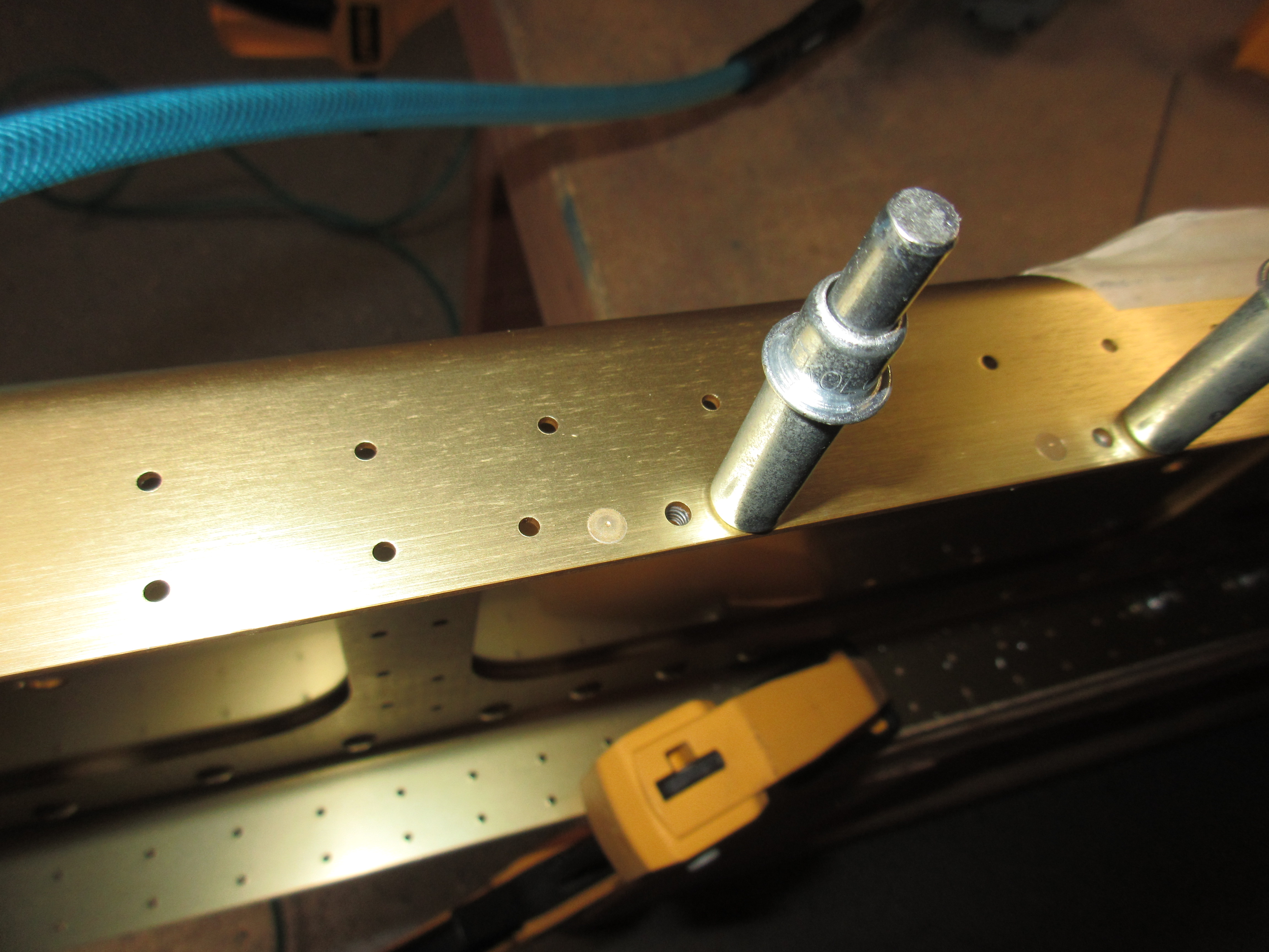
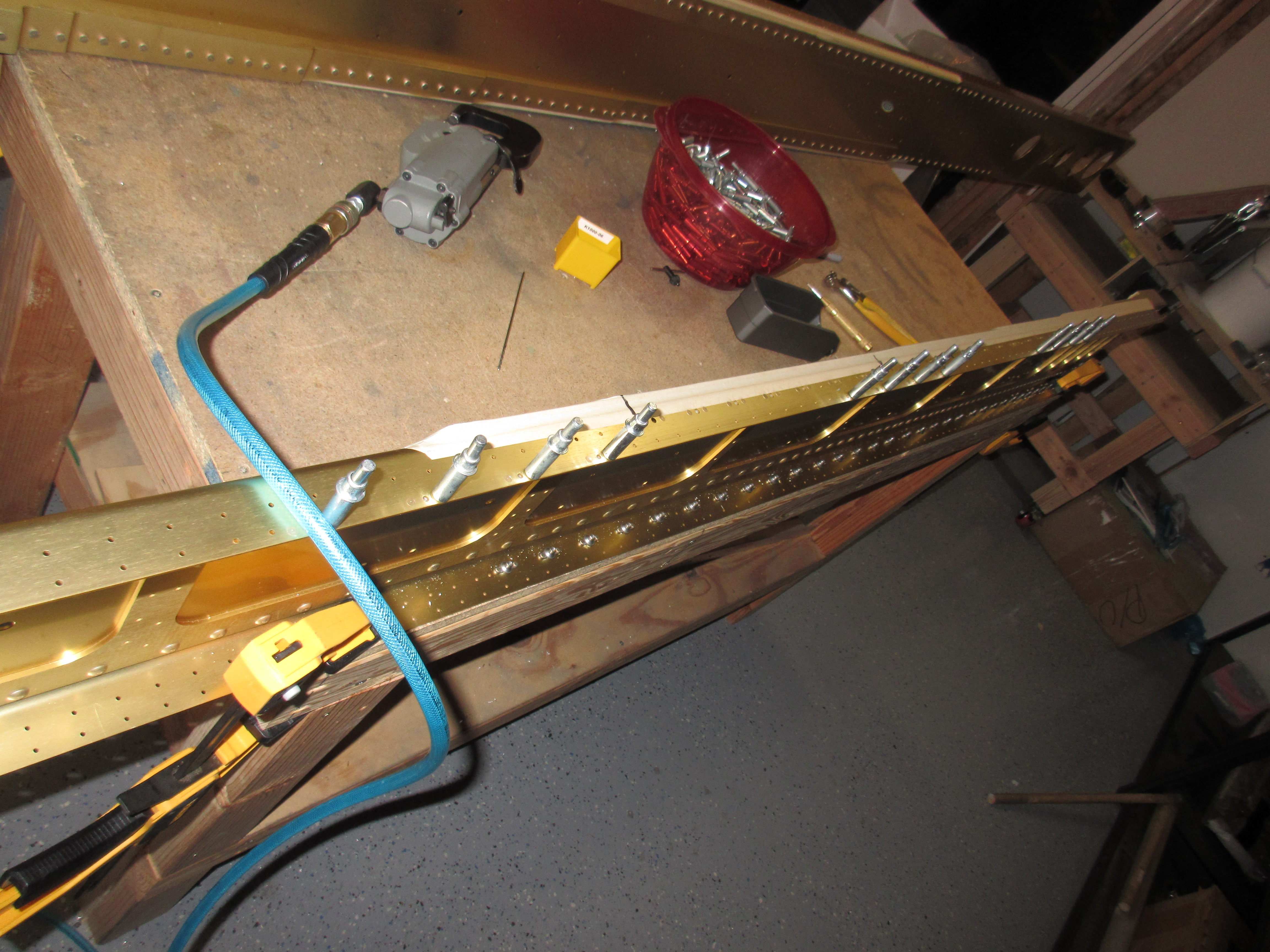
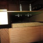
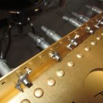
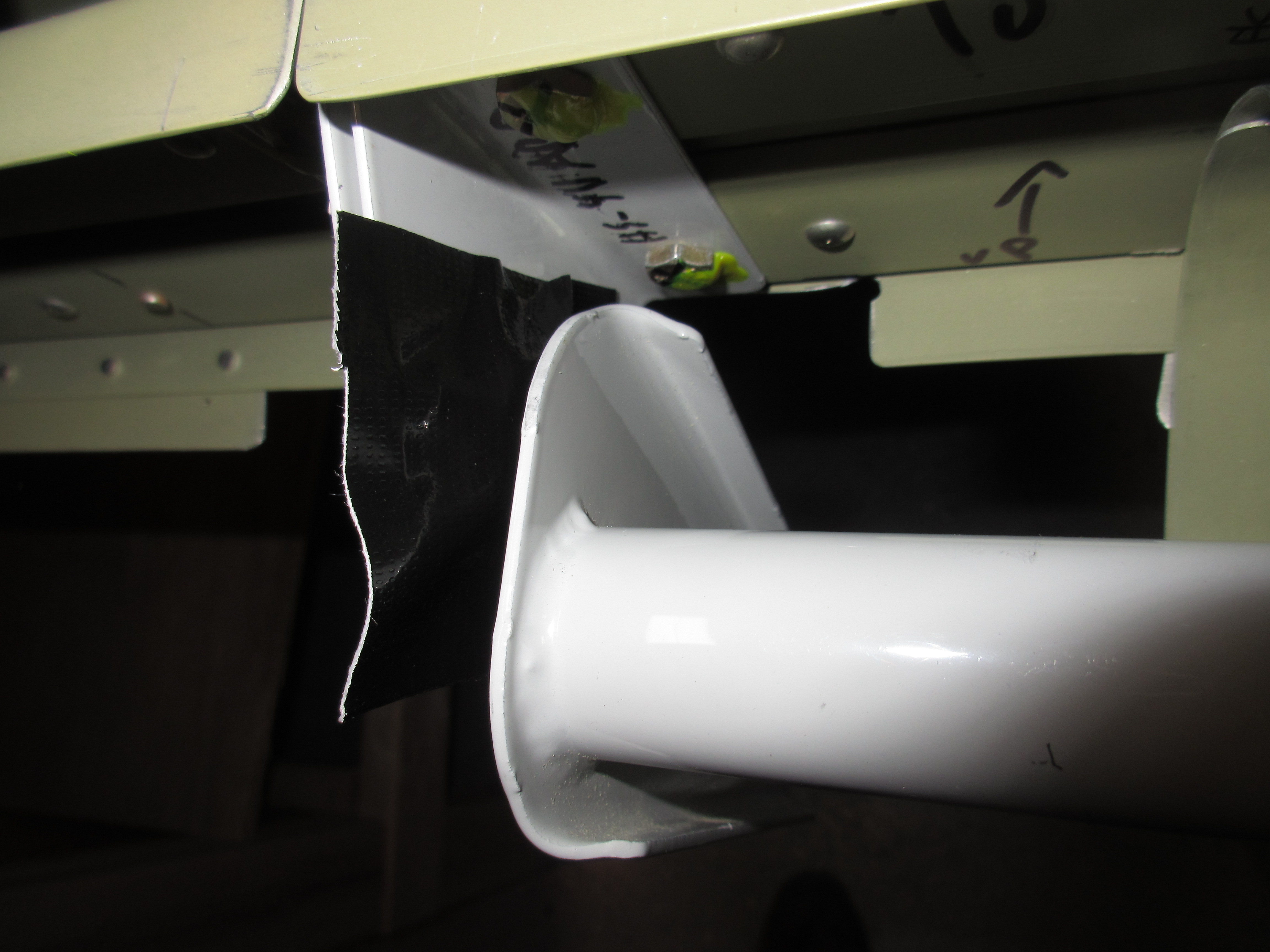
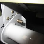
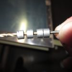
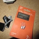
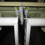
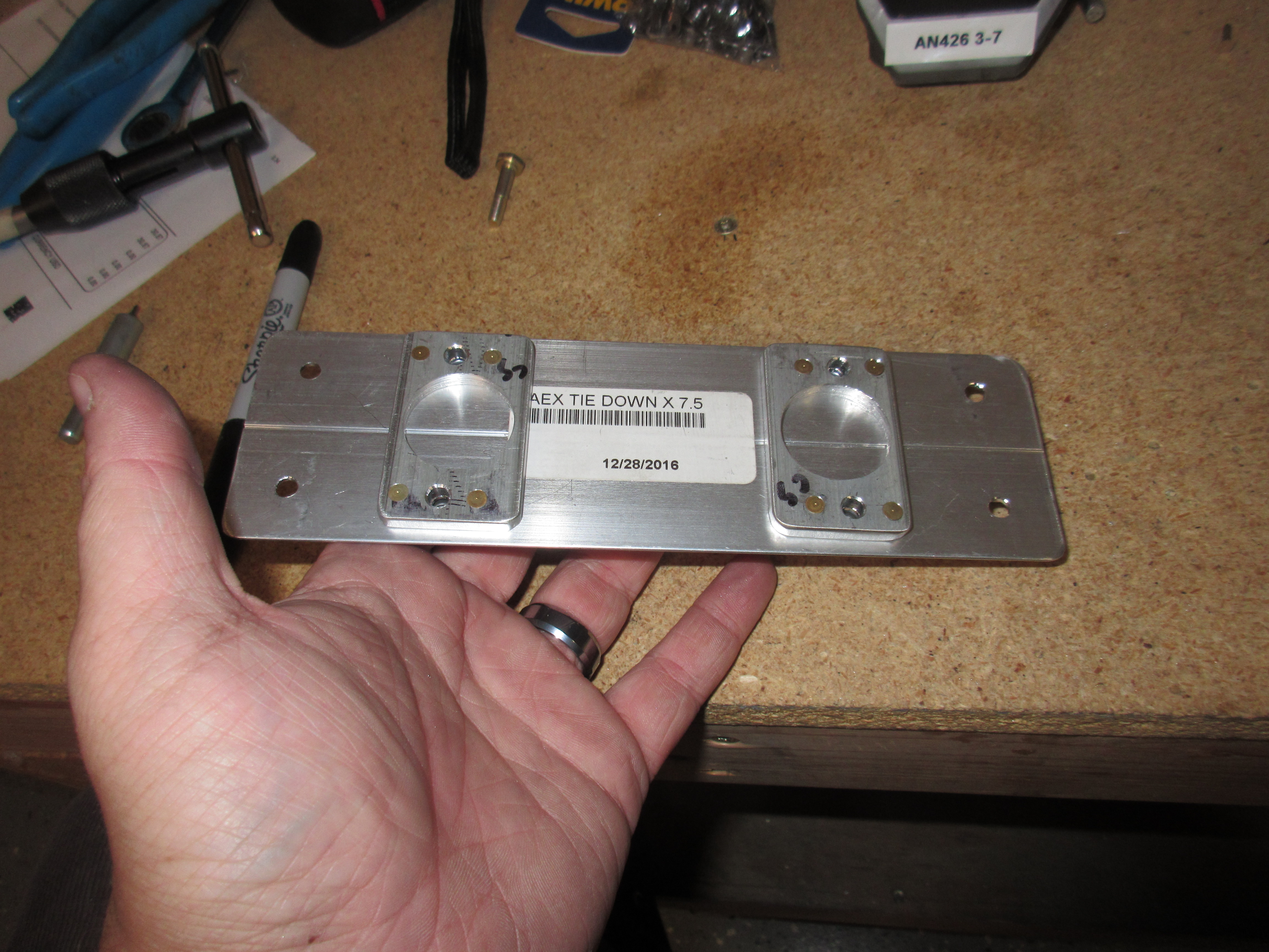
I actually fabricated some parts from the plans tonight.  This section of the plans has us fabricate the tiedown brackets that bolt to the main spar and help secure the aileron bell cranks as well.  There was a good bit of fabrication from raw materials so it was pretty much, but just a bit slower than I usually work.  I started off by tapping the holes in the AEX tie down stock for a 3/8 x16 threaded eye bolt. I had to actually run out to Ace hardware and pickup a tap and tap handle to get this done, so I did that while I was grabbing some dinner.  The plans calls for us to go 1″ of depth, so I wrapped some tape around the tap to mark 1″, and clamped the AEX stock to my work bench to start the process.

Almost finished with tapping this one

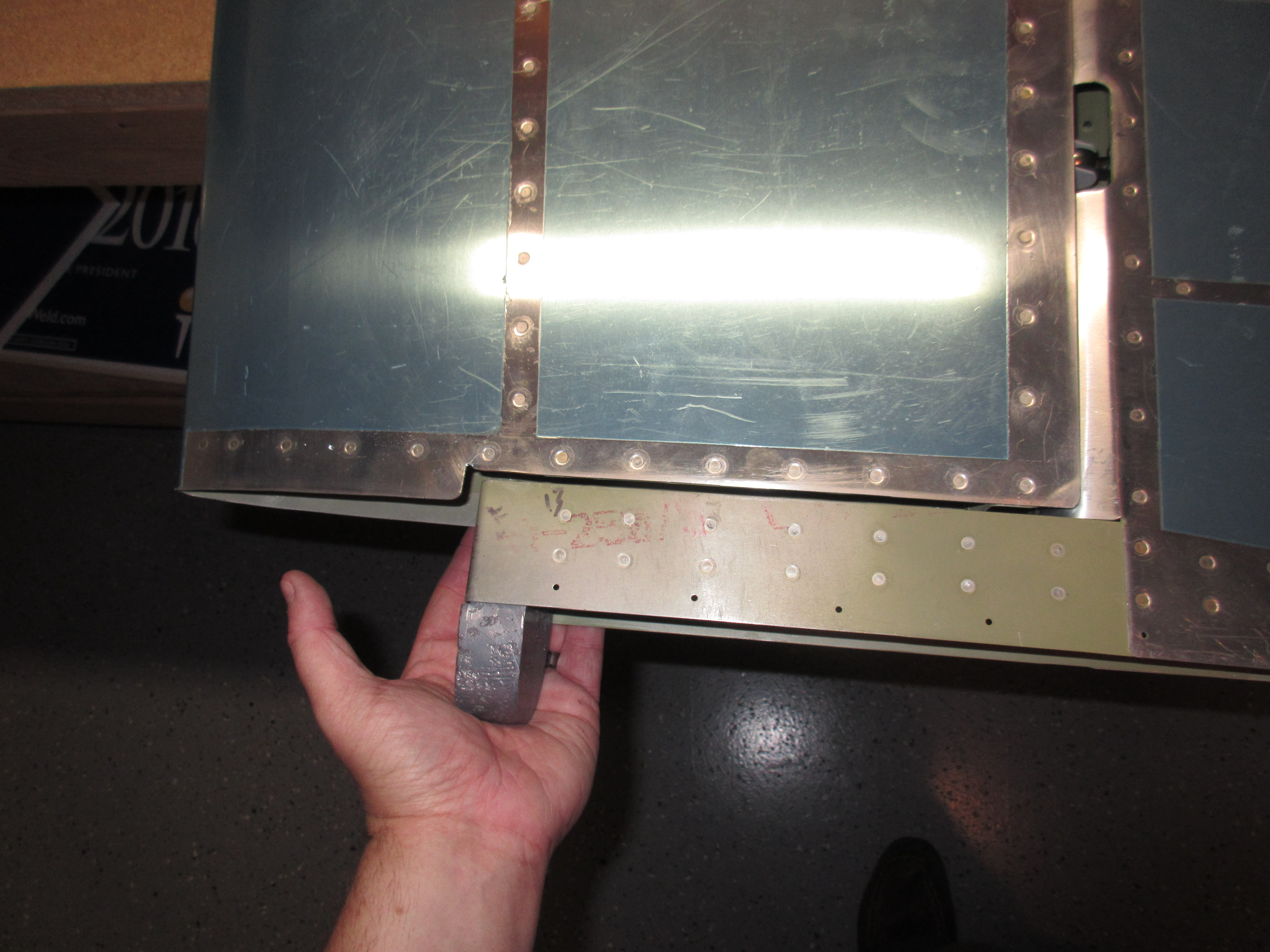
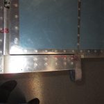
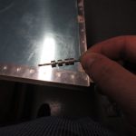
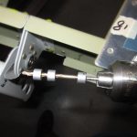
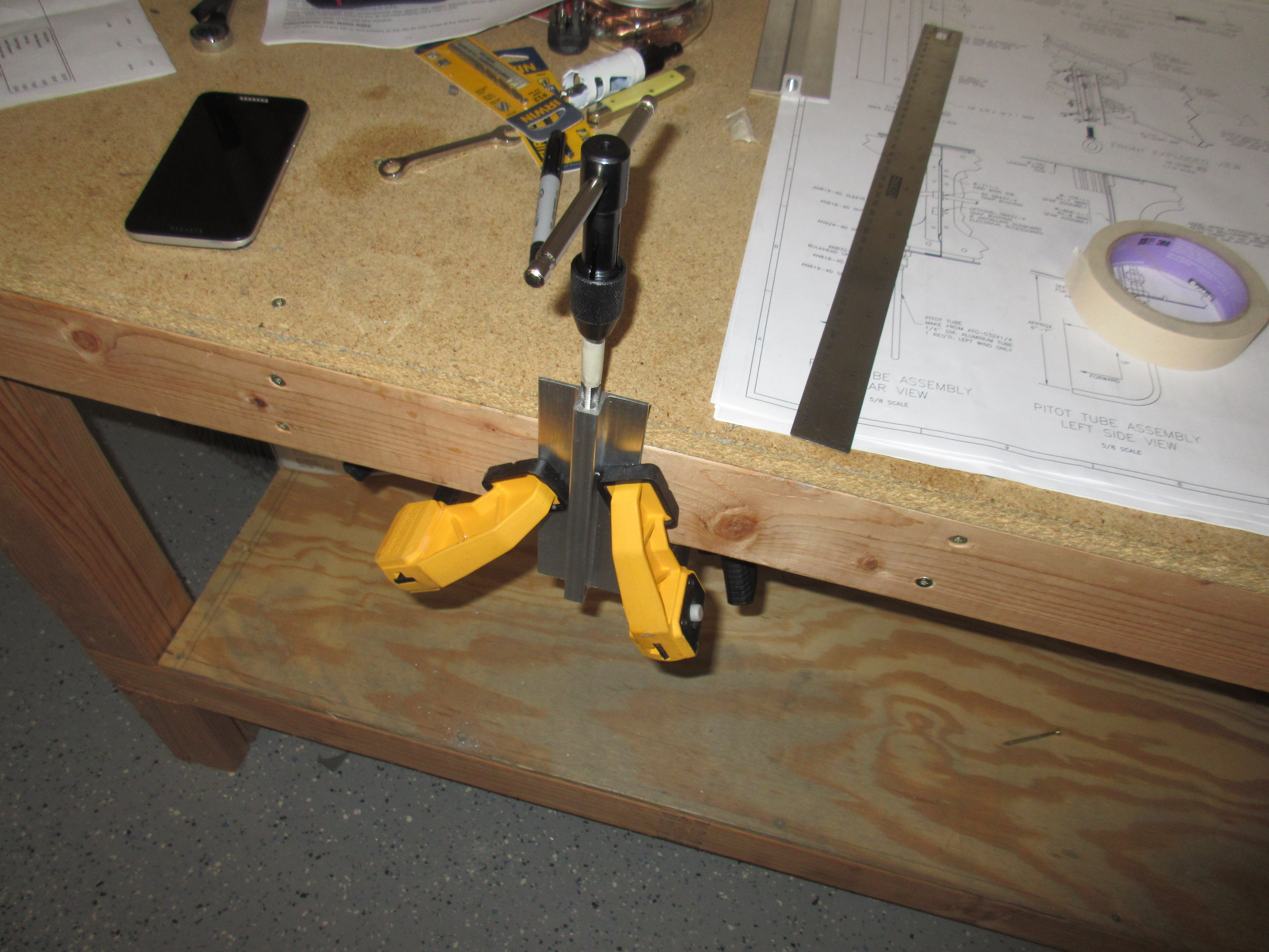
I have done this process before on other projects, so I lubed up the tap with some Boelube and slowly worked the tap into the AEX stock making sure it was straight.  I gave it a few twists into the metal, and then backed the tap out to clear some of the chips. I kept repeating this advance and retreat process until I had the full 1″ of depth as called for in the plans, and then did the second piece of AEX stock for the other wing.  The reason I did this first was so that if I messed up tapping the metal, I could just flip the piece around and use the other end, since both ends are identical.  Once I was happy with the threads I trimmed the 1/32″ of an inch that Vans calls for in the plans.  I am not sure why we need to take the AEX stock down from 7 and 16/32″ to 7 and 15/32″ using a bandsaw very carefully and then finishing it on the bench grinder.

New threads are kind of hard to see in this photo, but they are there!

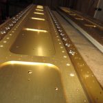
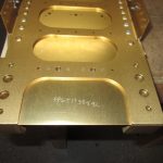
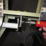
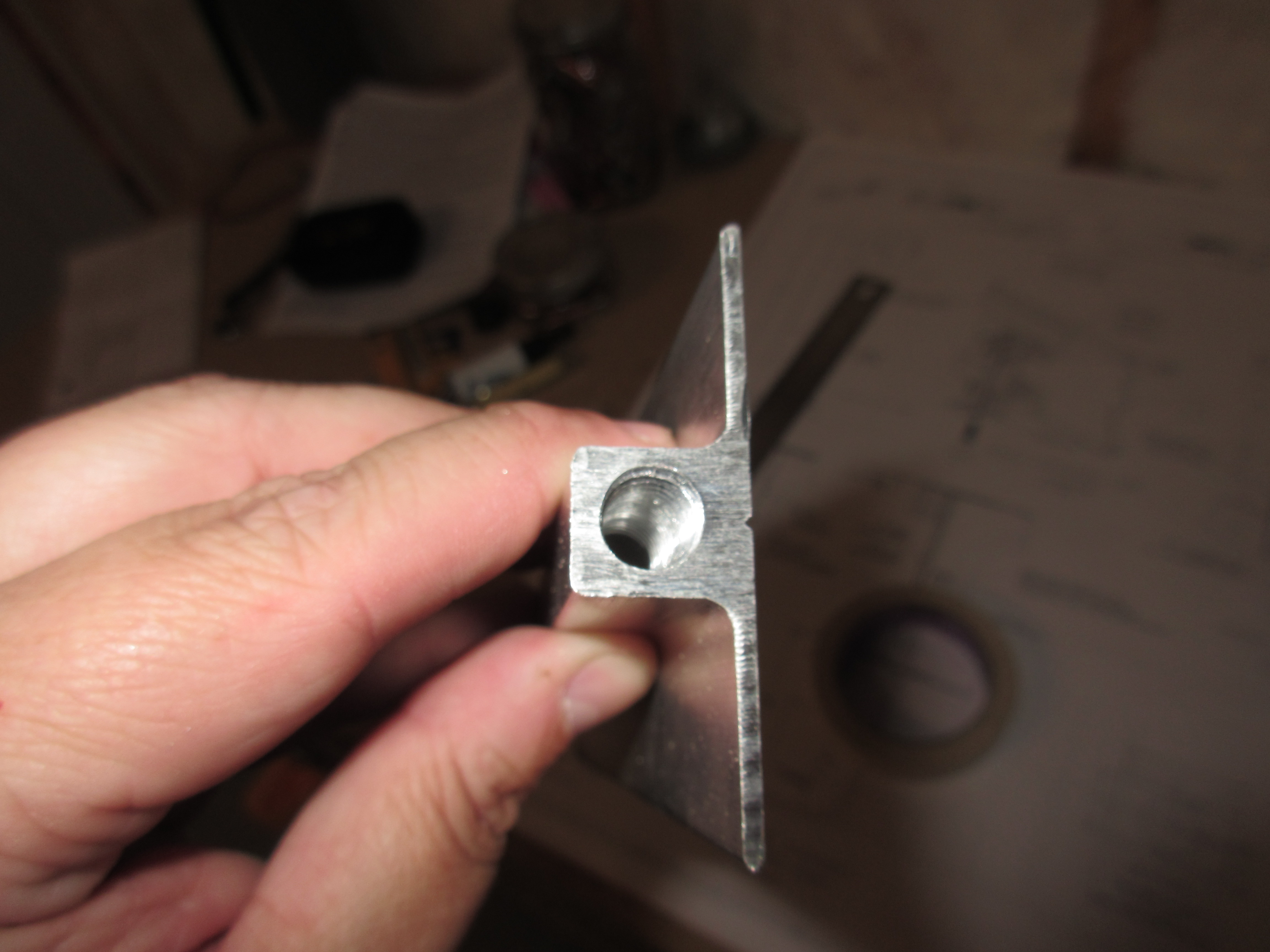
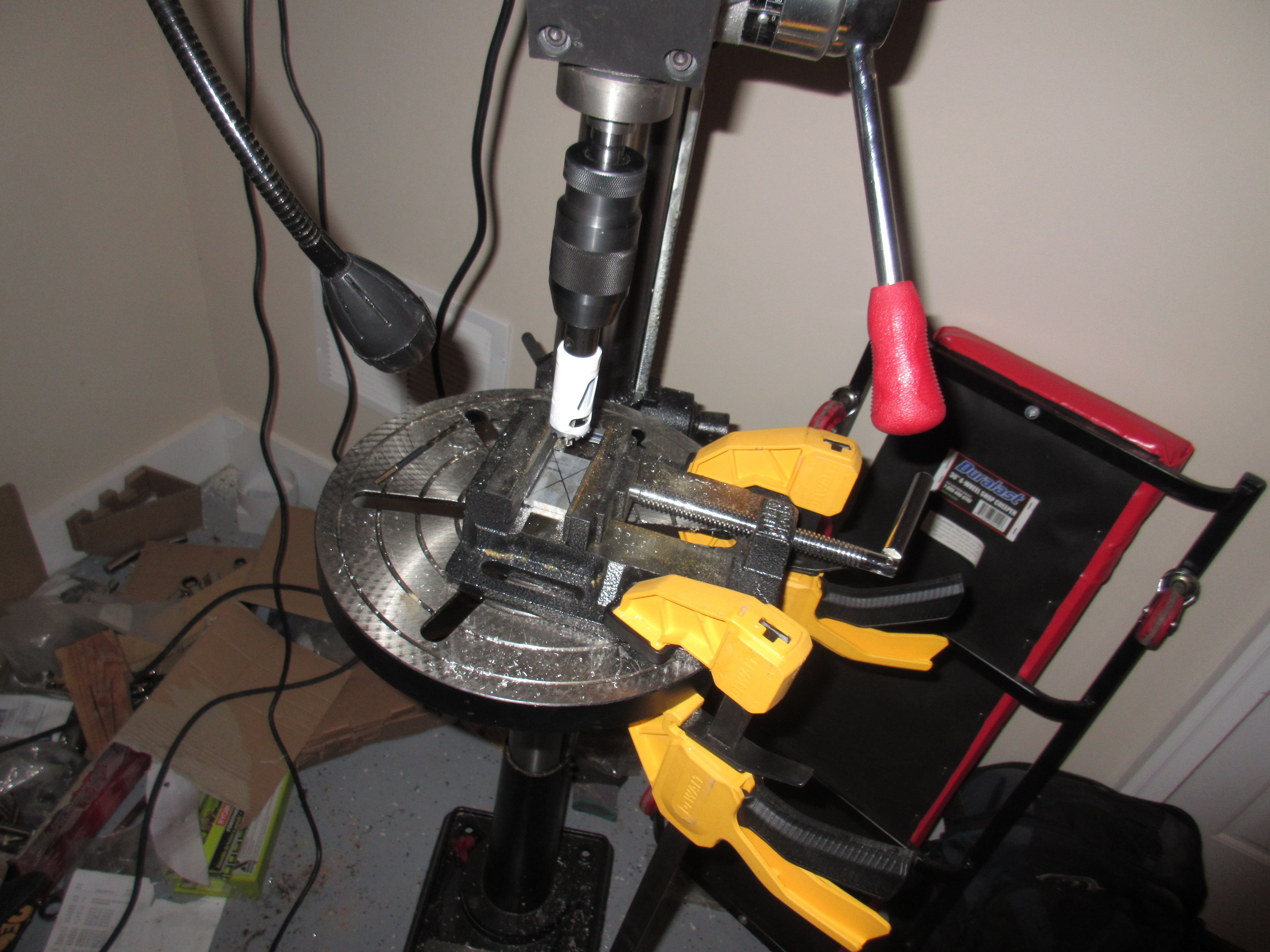
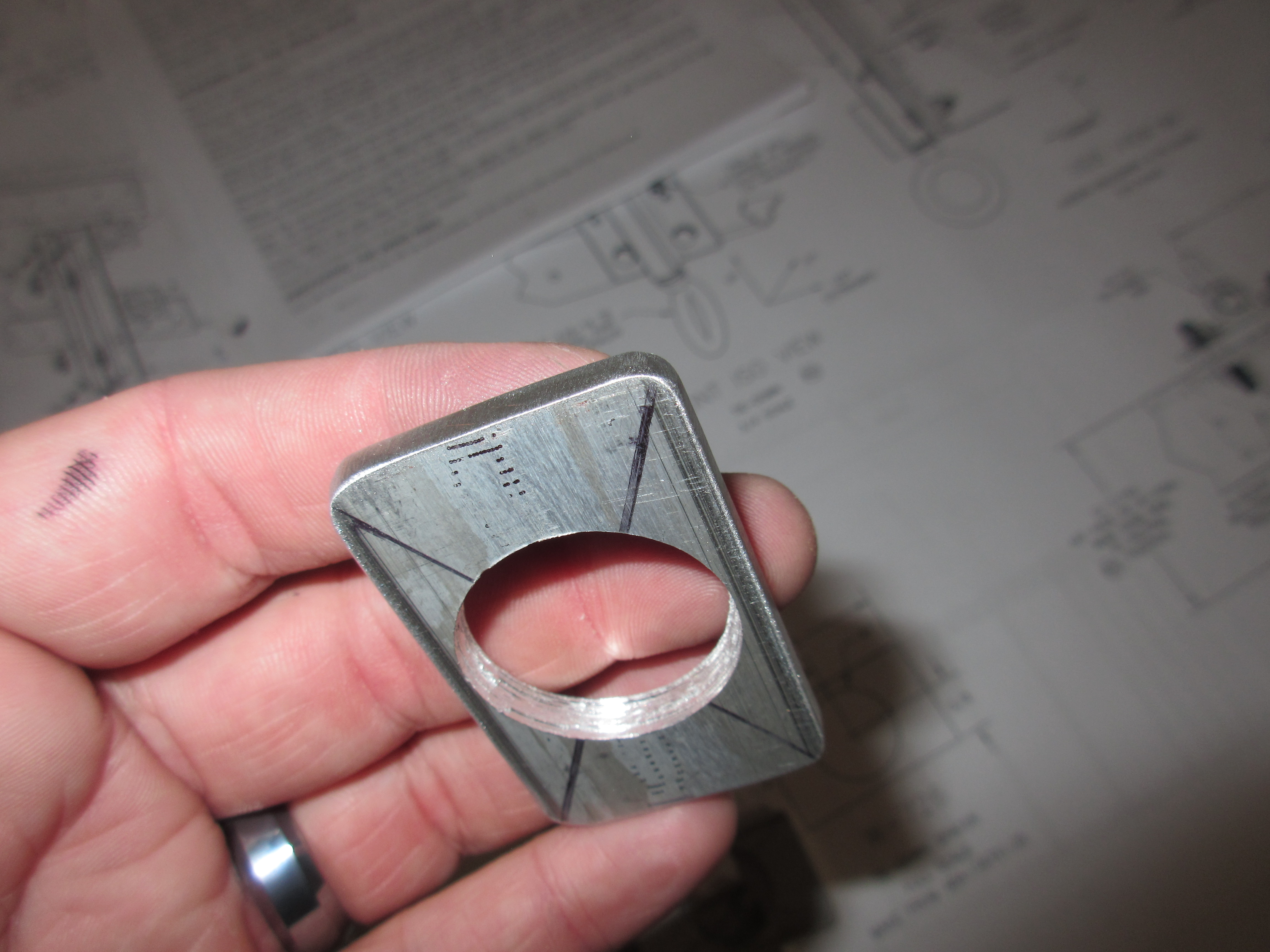
Next up was to fabricate 4 spacers to fit between the tie down bracket and the main spar. These are called W-726 and the plans has a full size drawing of what they are supposed to look like, so they are easy to make from the AB4-187×1.25 stock.  I measured them out for 2″ on my bandsaw and cut them out.  The next process was to mark the center and then drill the lightening hole using the drill press and a 1″ bi-metal hole cutter.

After I had the lightening holes done on all 4 of these parts, I was happy with them and moved on to finishing their edges.  I ran them on the bench grinder to round the corners, and then deburred the edges nice and smooth on the scotchbrite wheel.  Then I deburred the lightening hole to make it smooth. They were ready to be match drilled with the tiedown bracket and main spar.

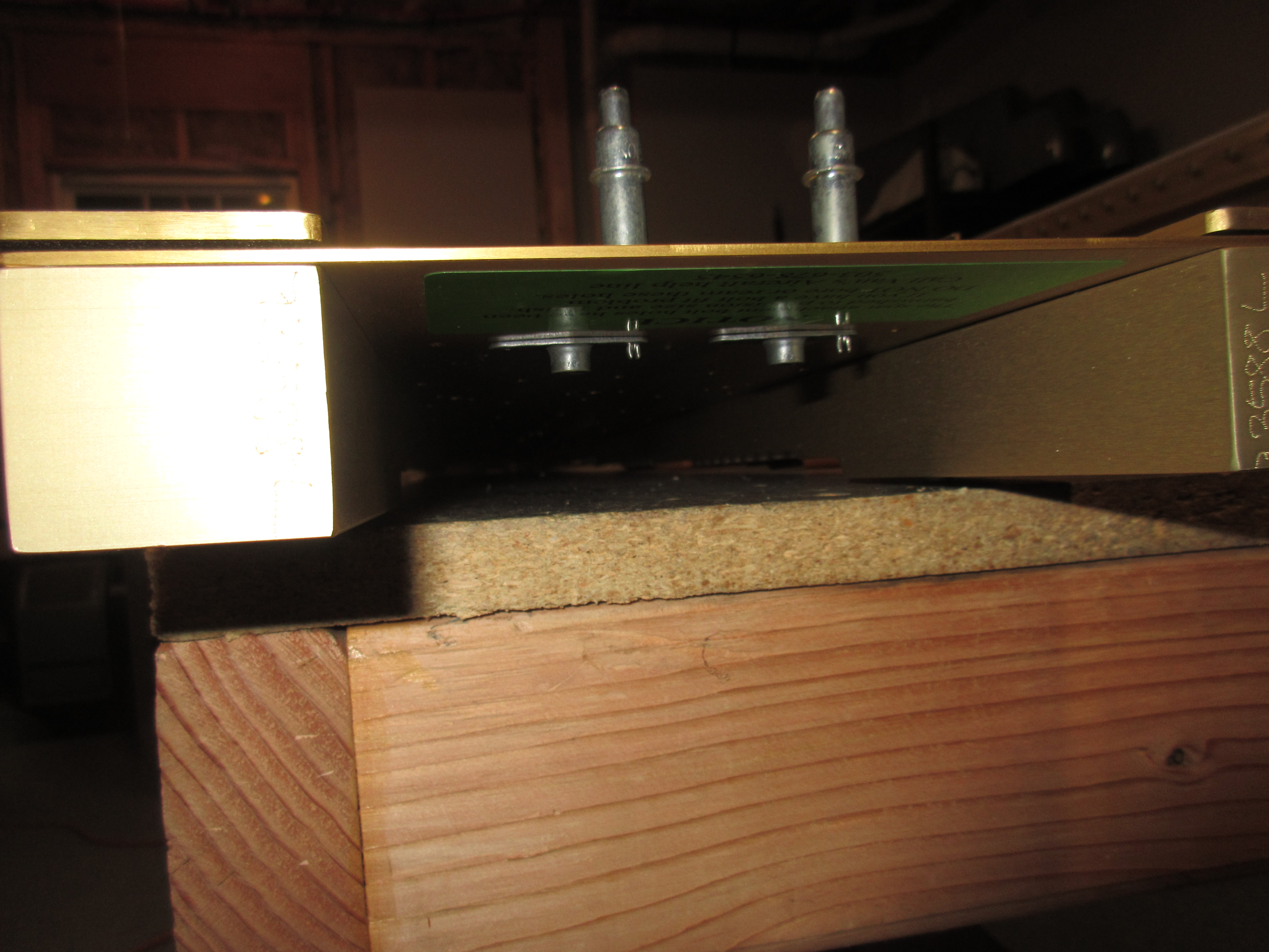
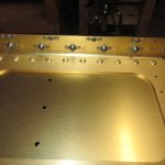
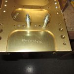
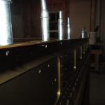
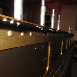
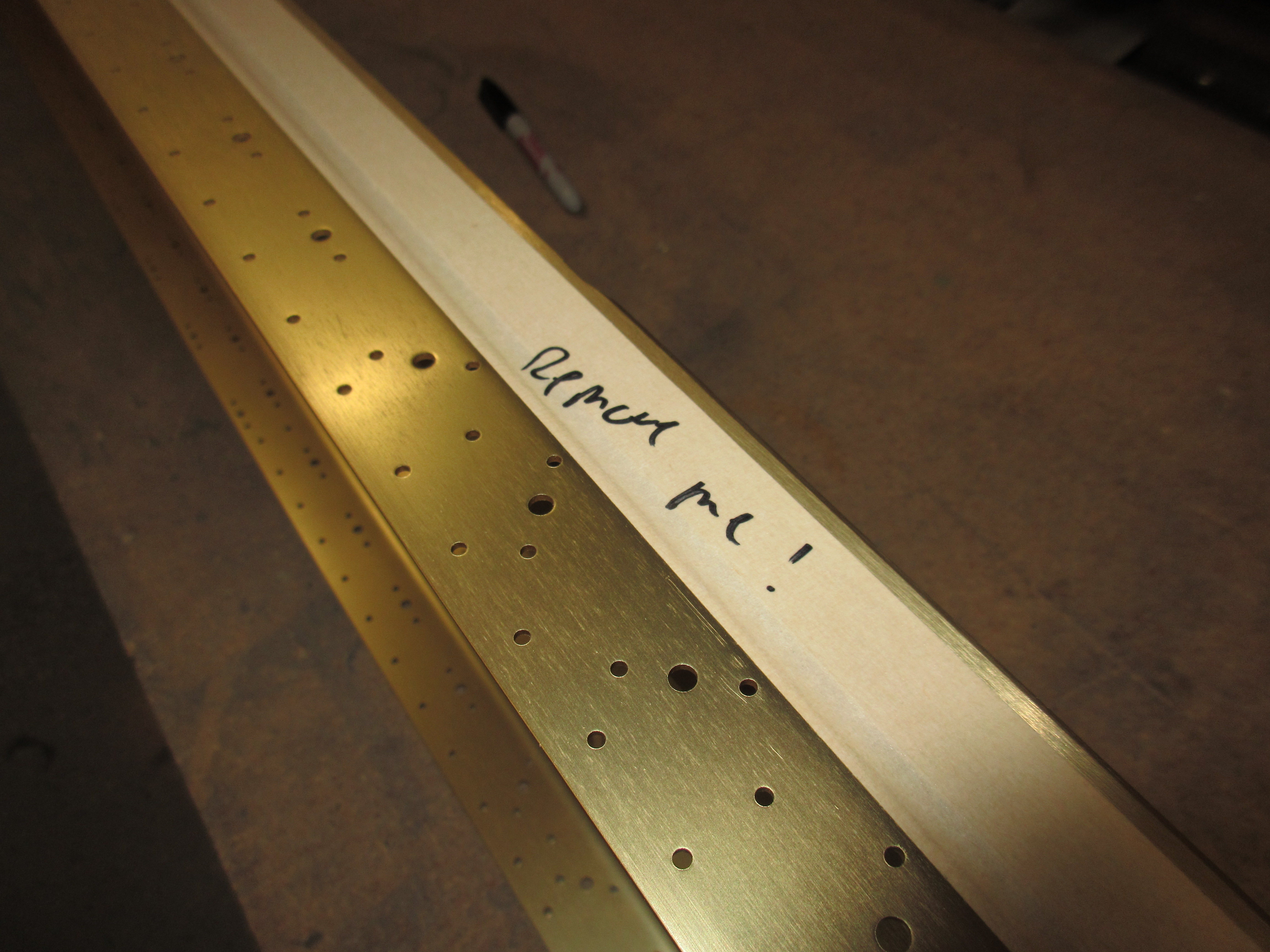
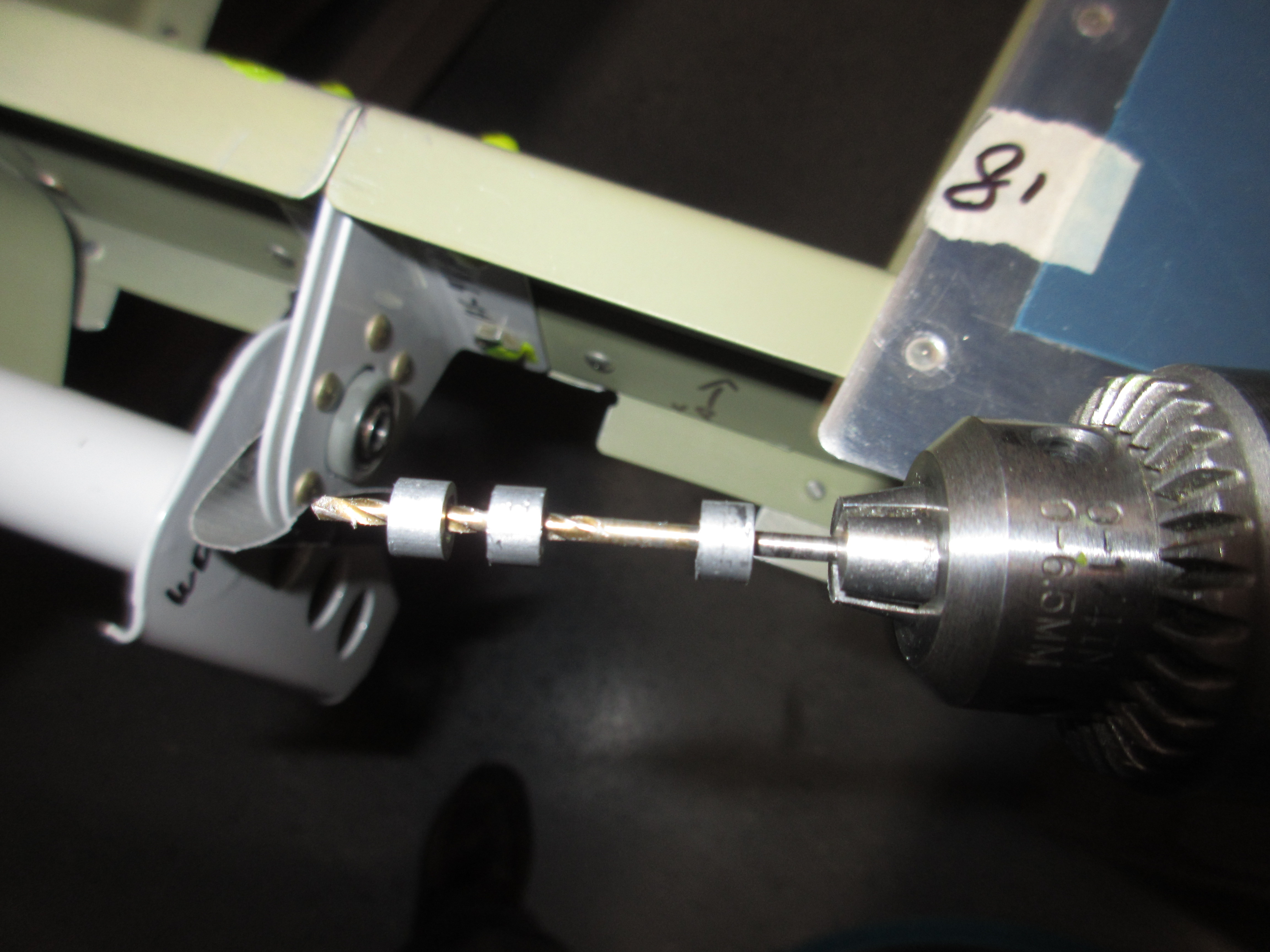
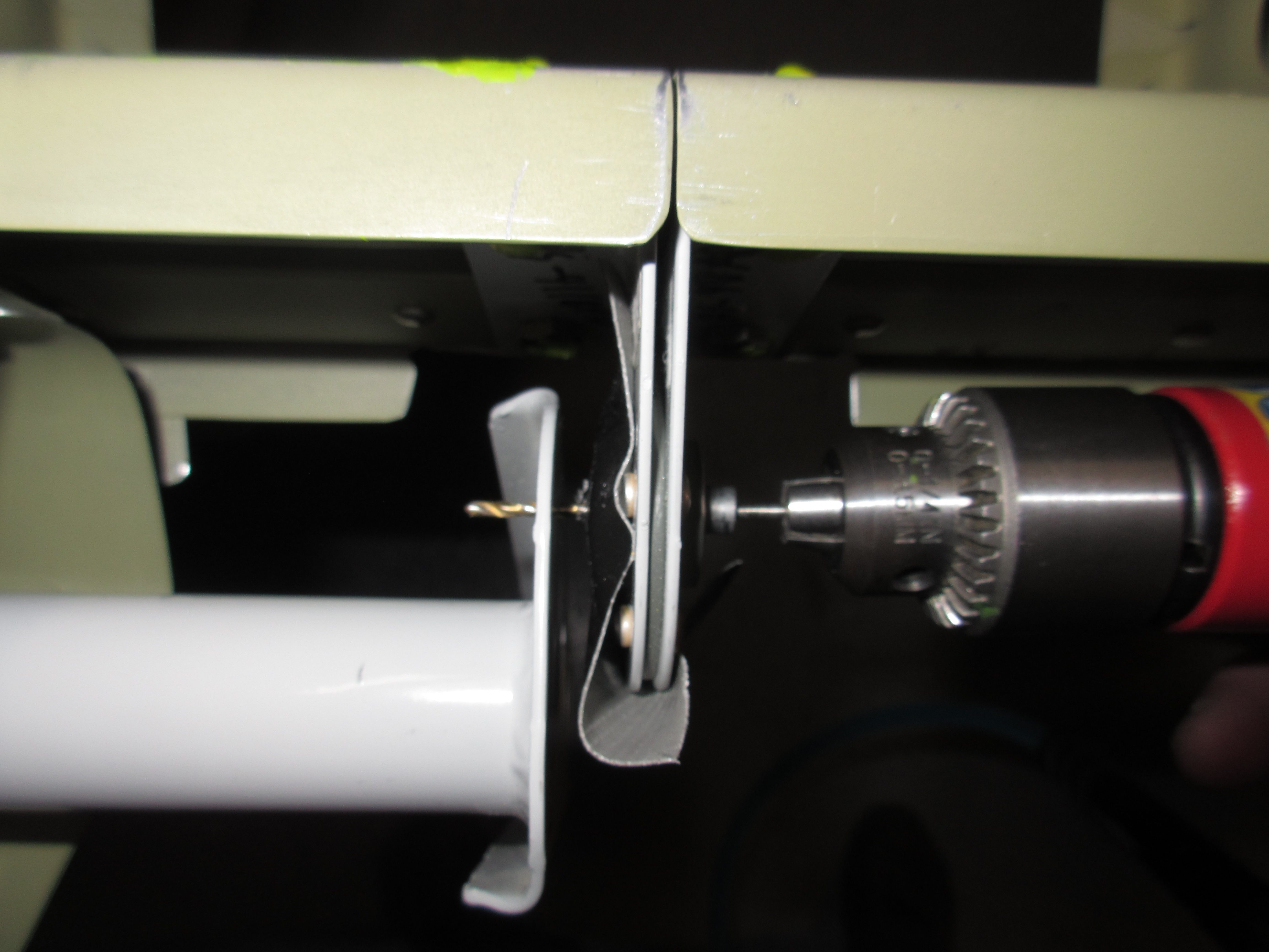
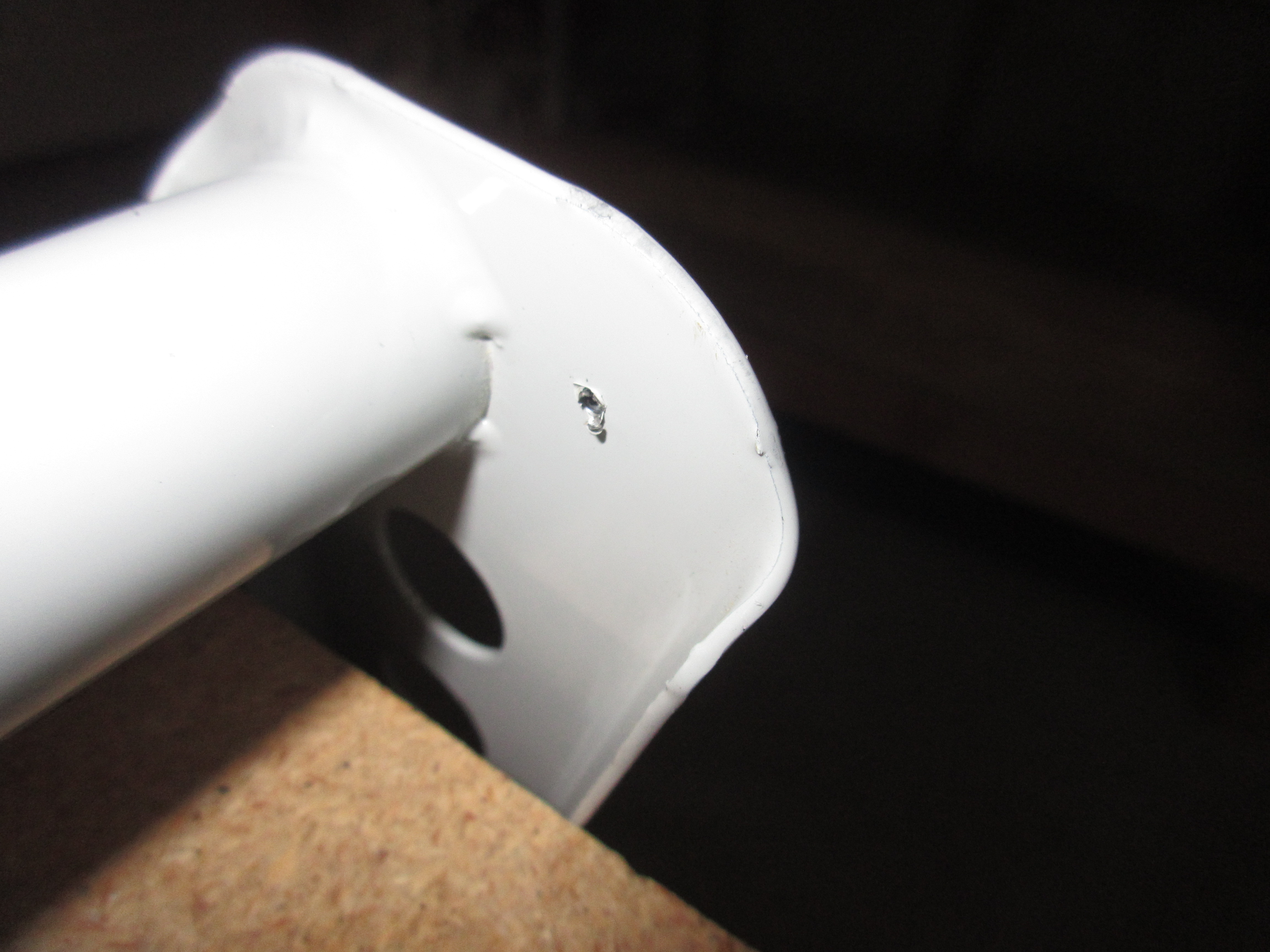
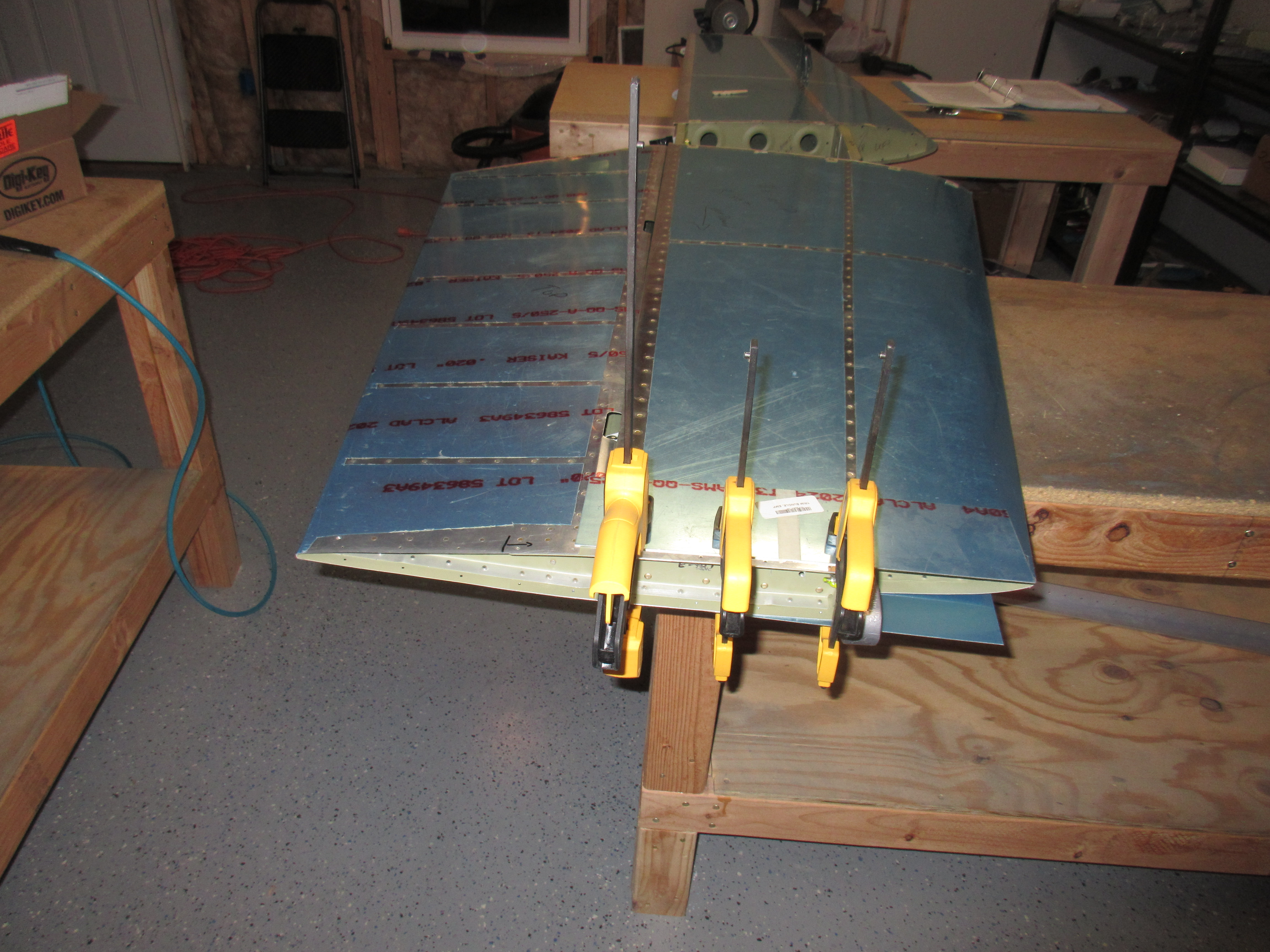
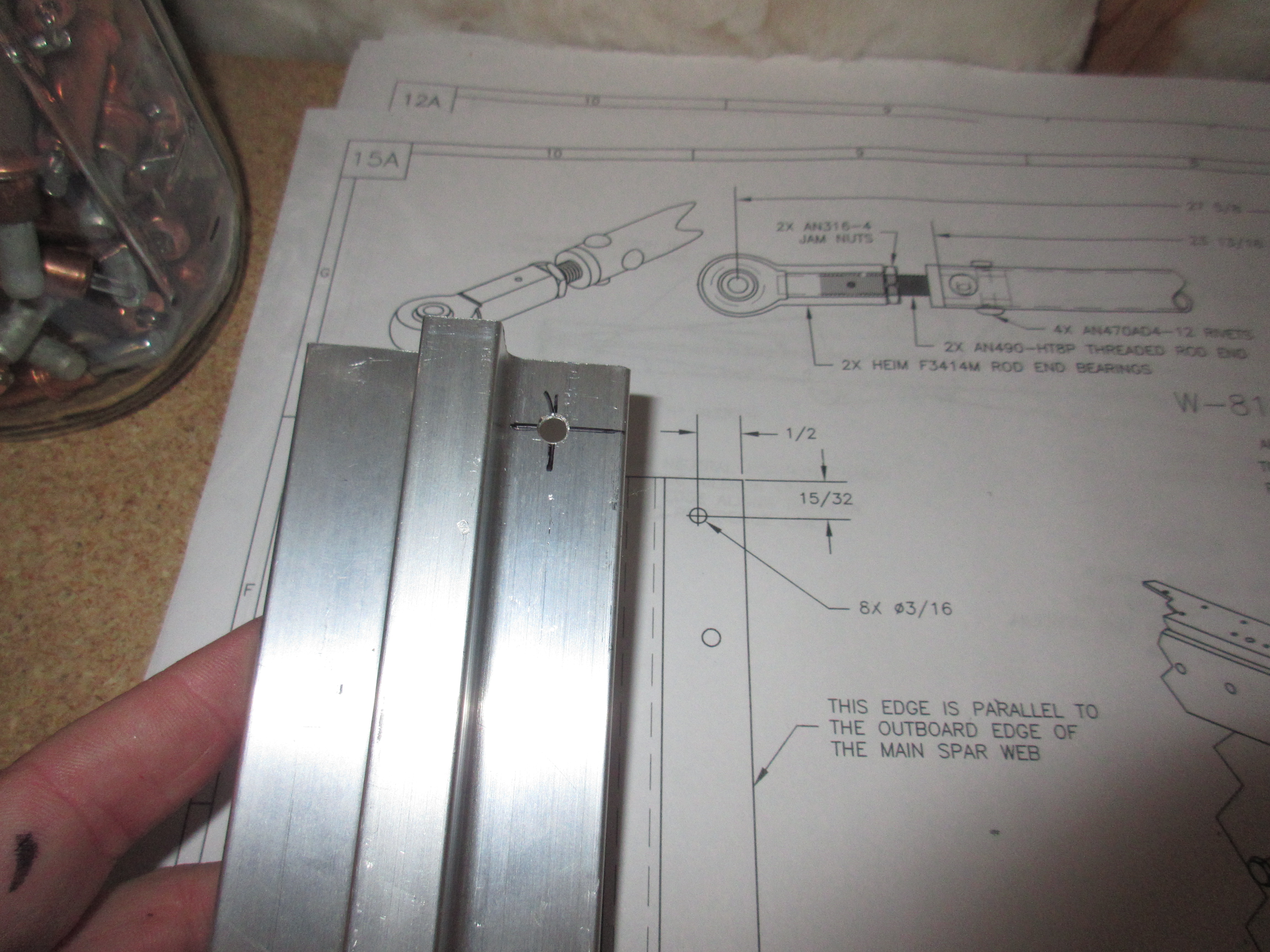
This next part required a bit of measuring, squaring up and clamping to make sure everything was perfect.  We first start out by drilling an index hole in the AEX tie down stock to be used to help guide it onto the main spar for easier back drilling.  The plans calls out the dimensions, I marked it up and drilled it on the drill press to make sure it was perfectly square, and then repeated the process for the other tiedown.

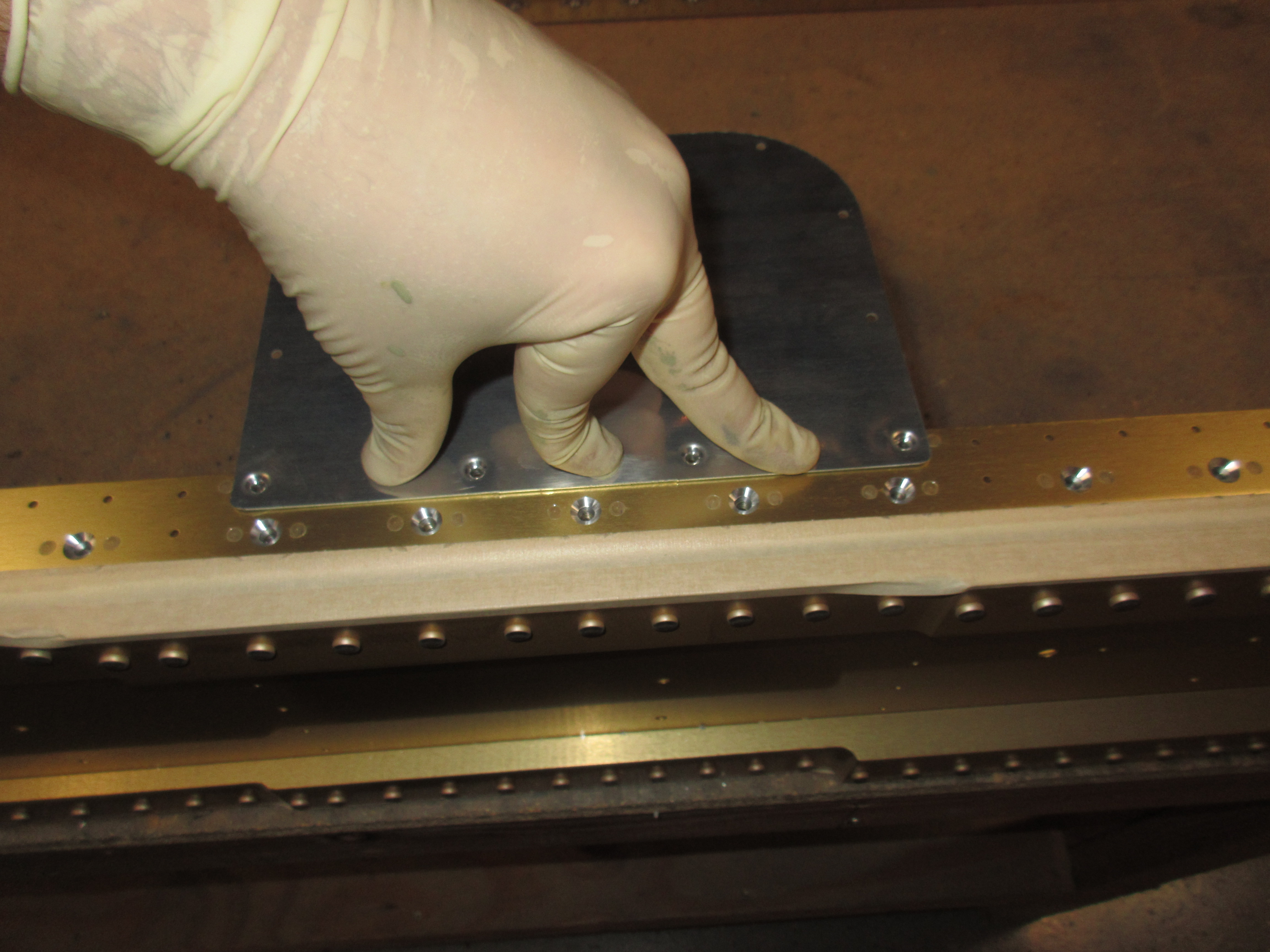
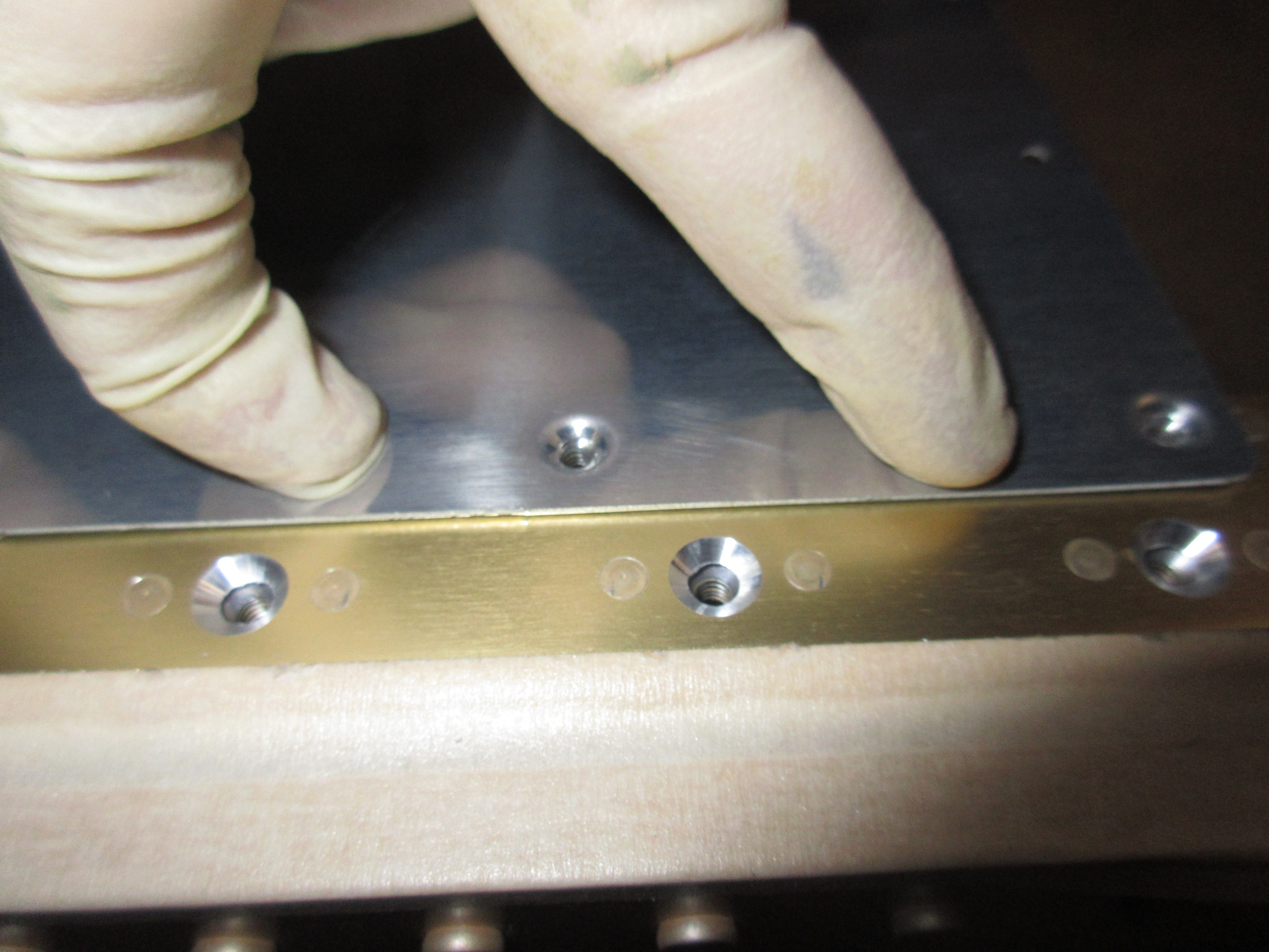
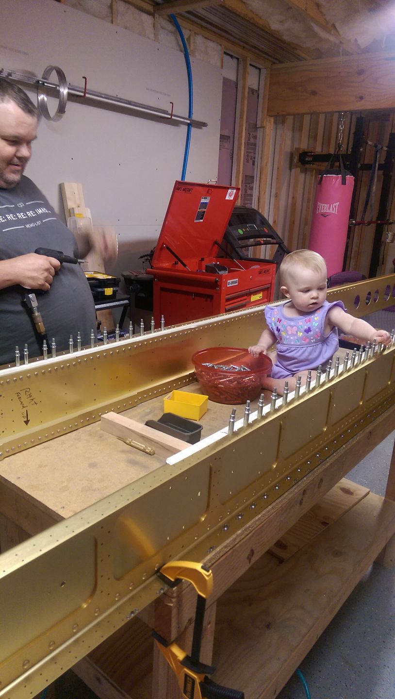
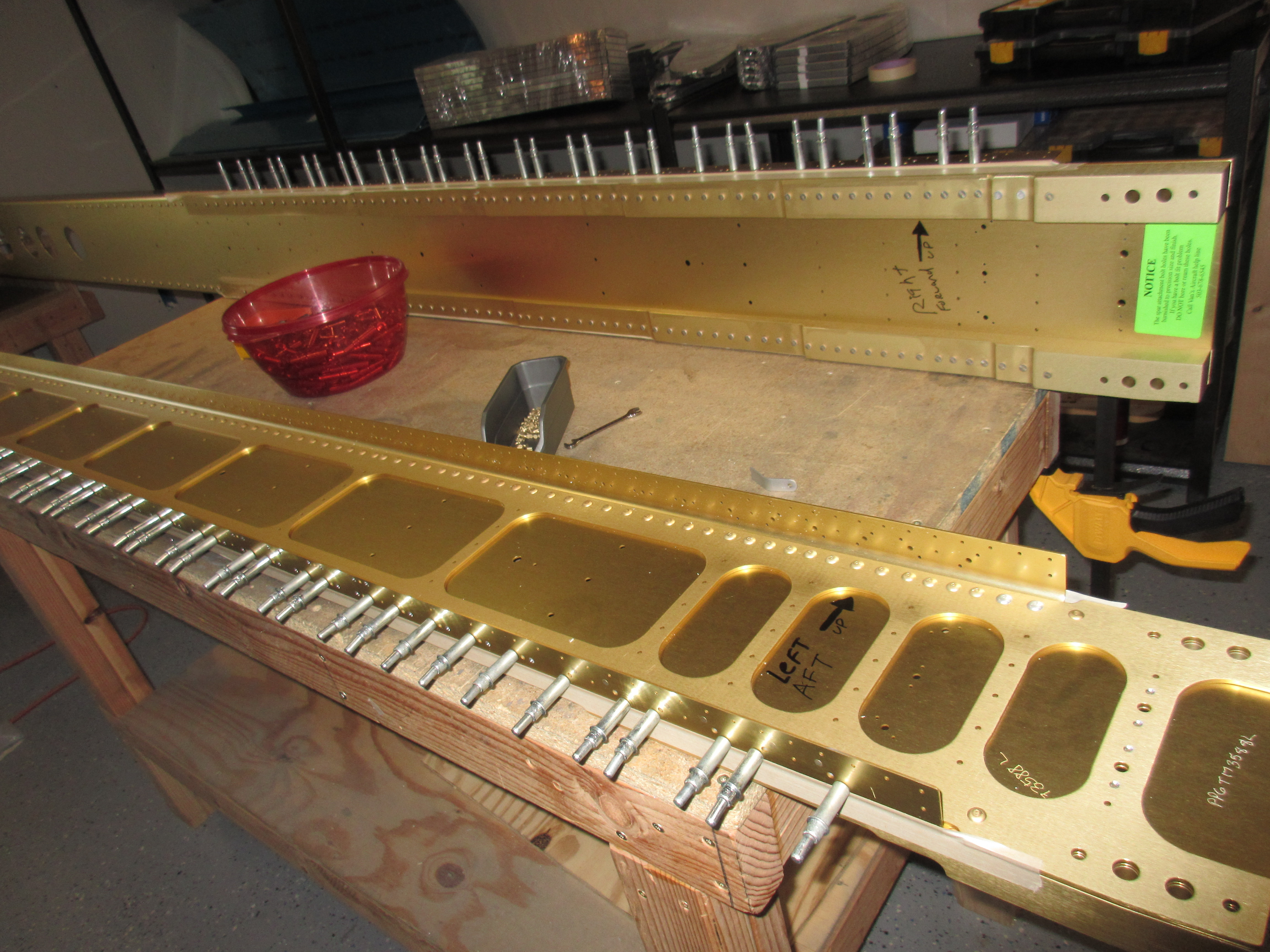
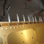
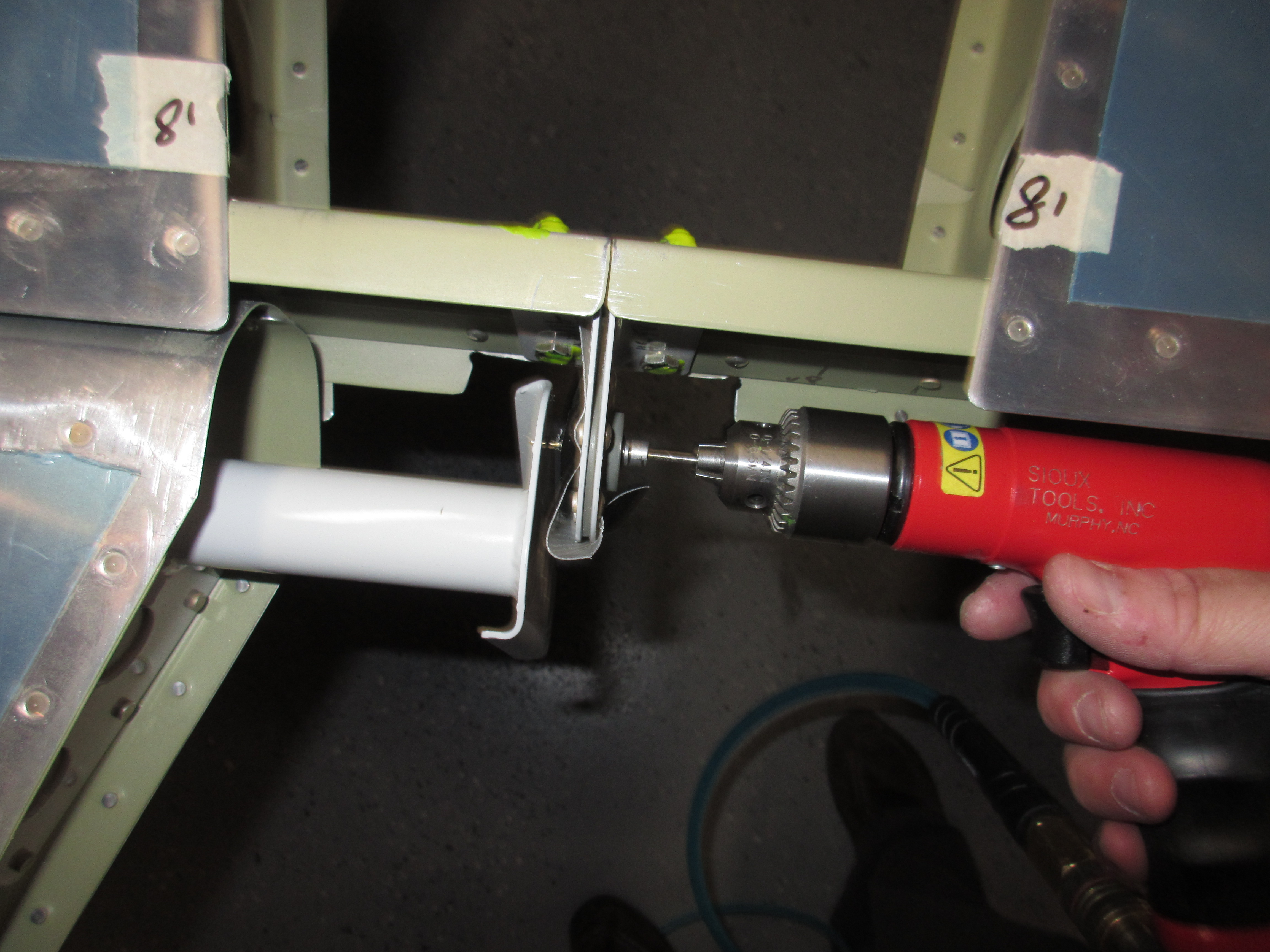
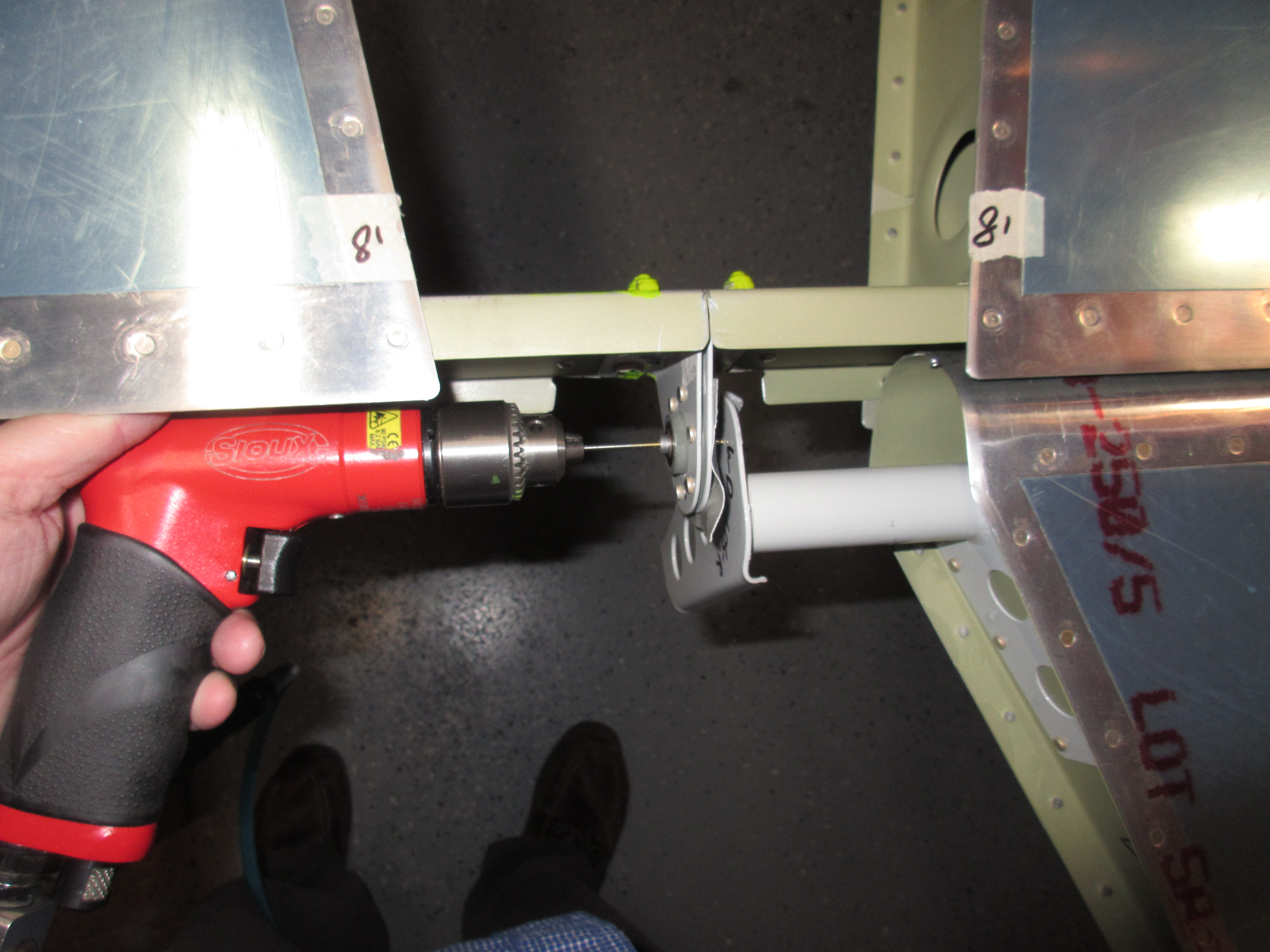
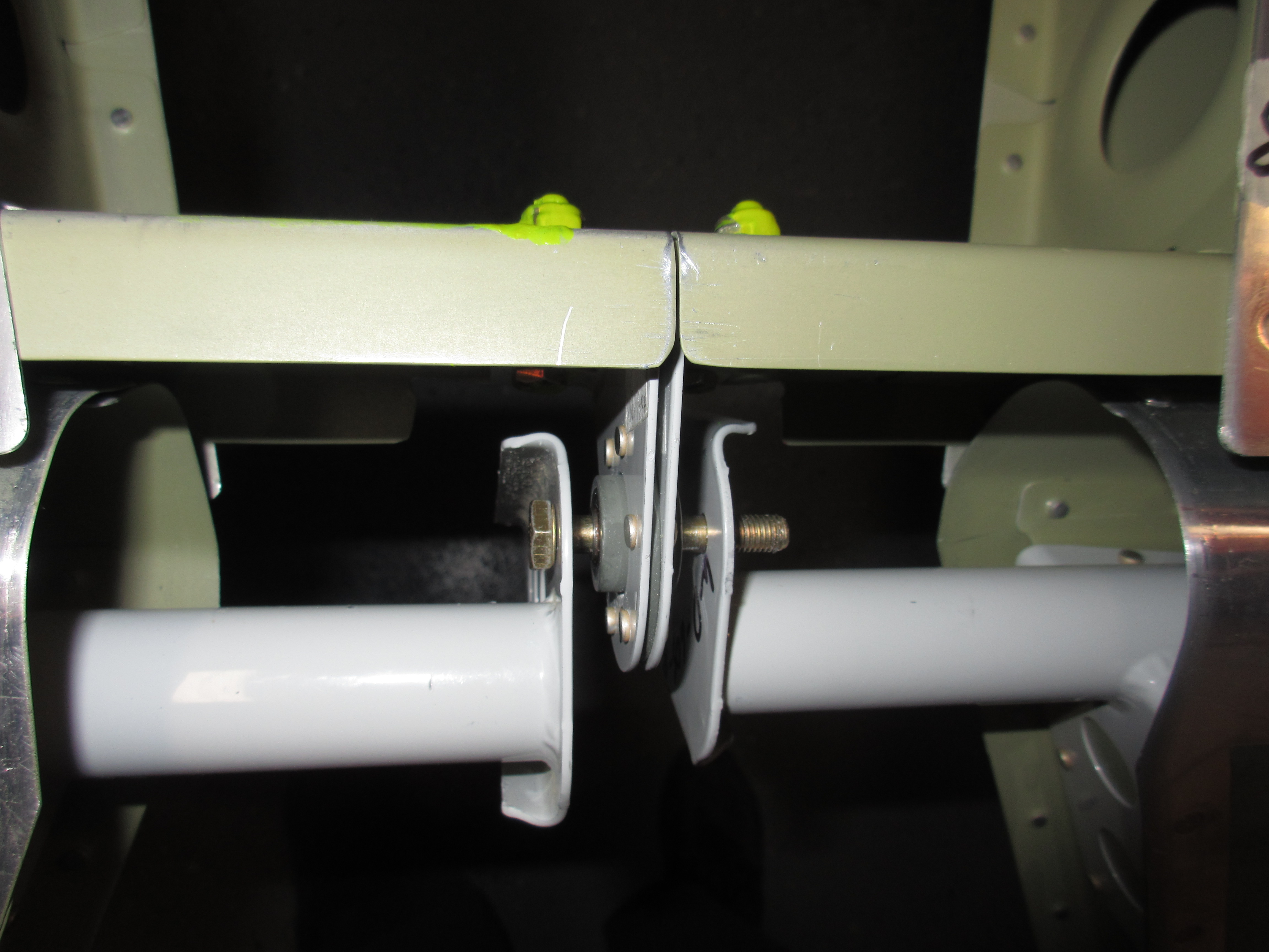
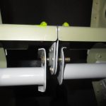
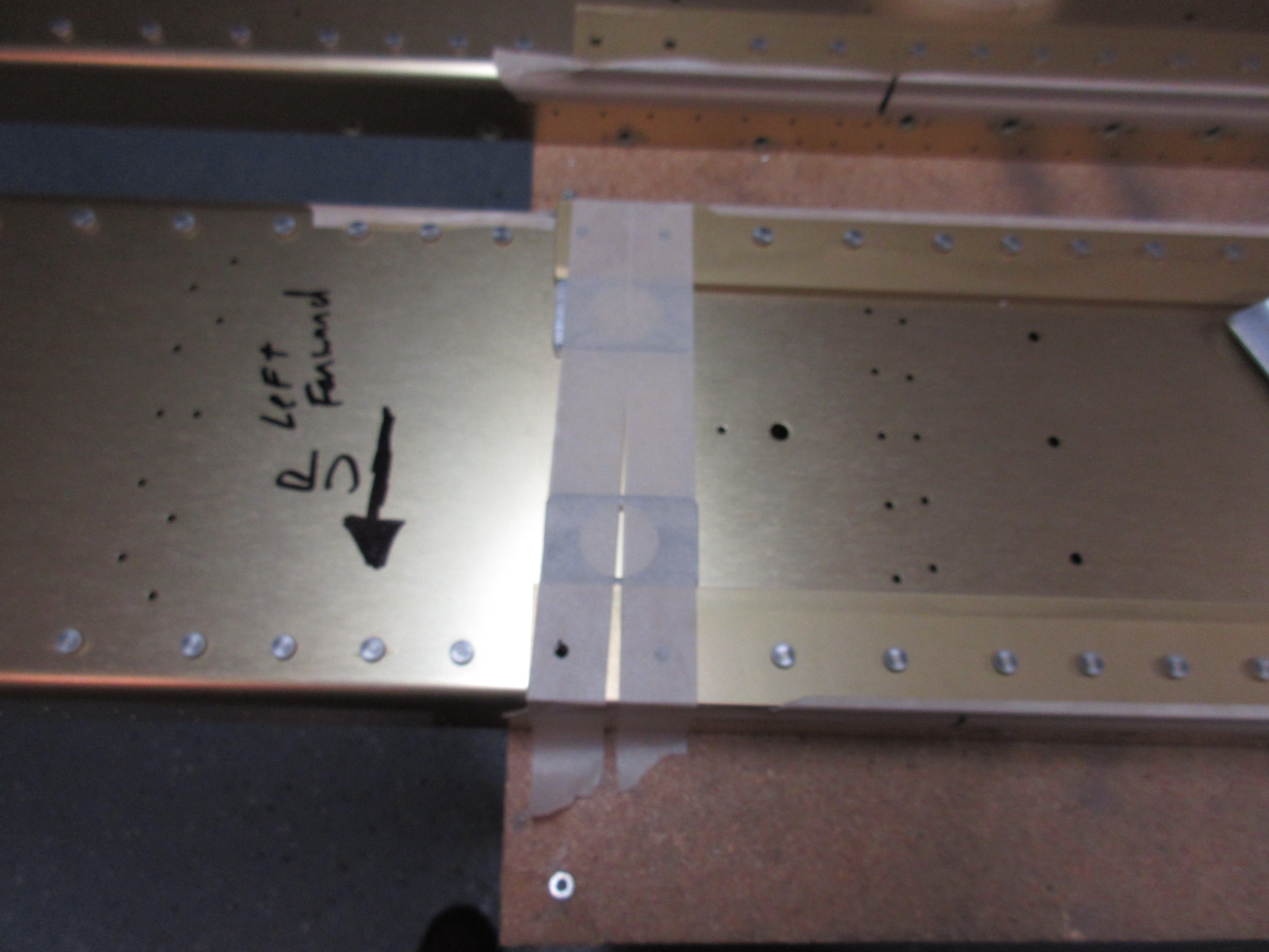
Then I used masking tape to hold the spacers on the main spars while I positioned the tiedown bracket and squared it up with the spar web using a square, using the index bolt to help with alignment.  Then I clamped it all down and back drilled everything using a #12 drill bit.

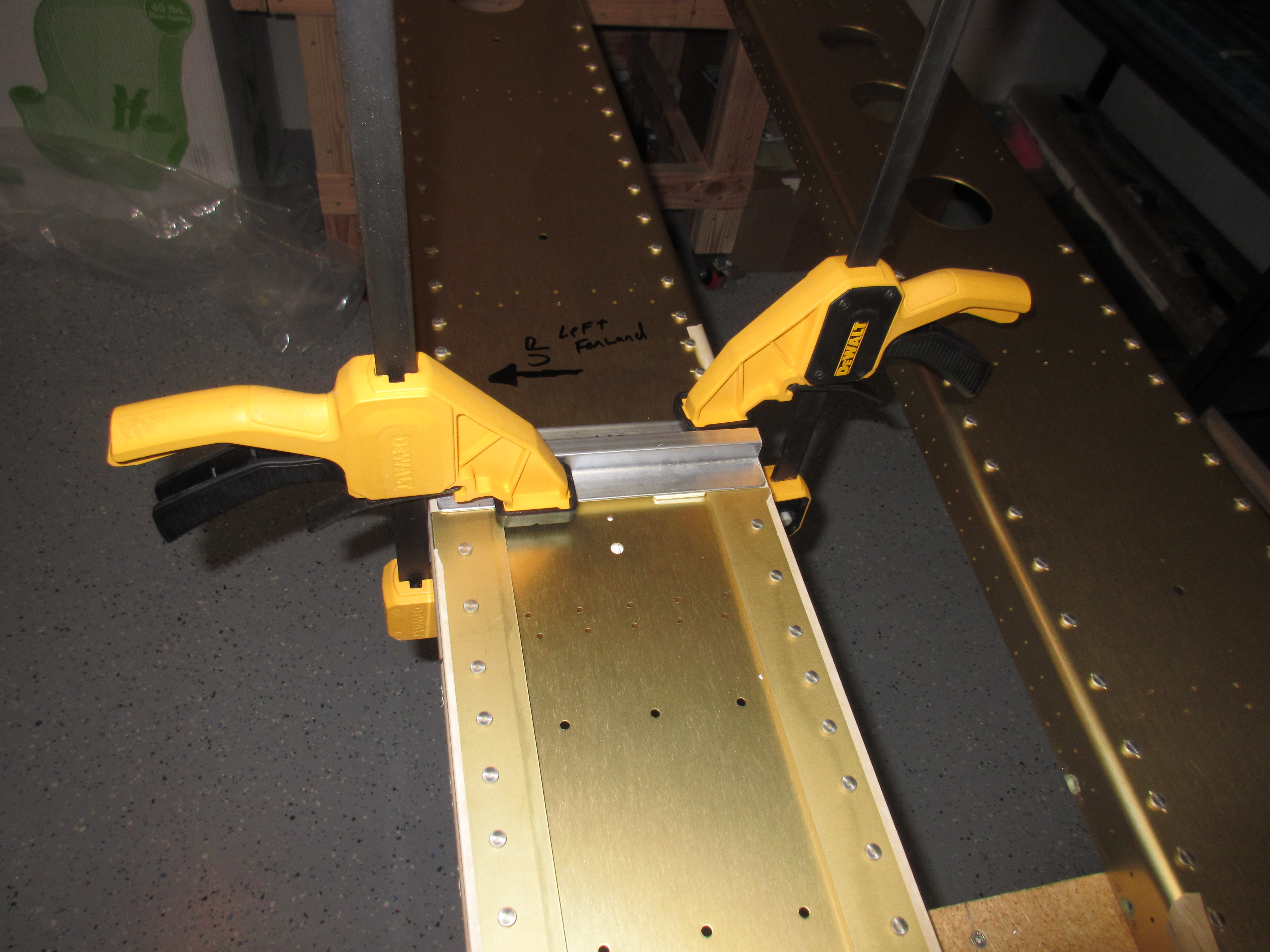
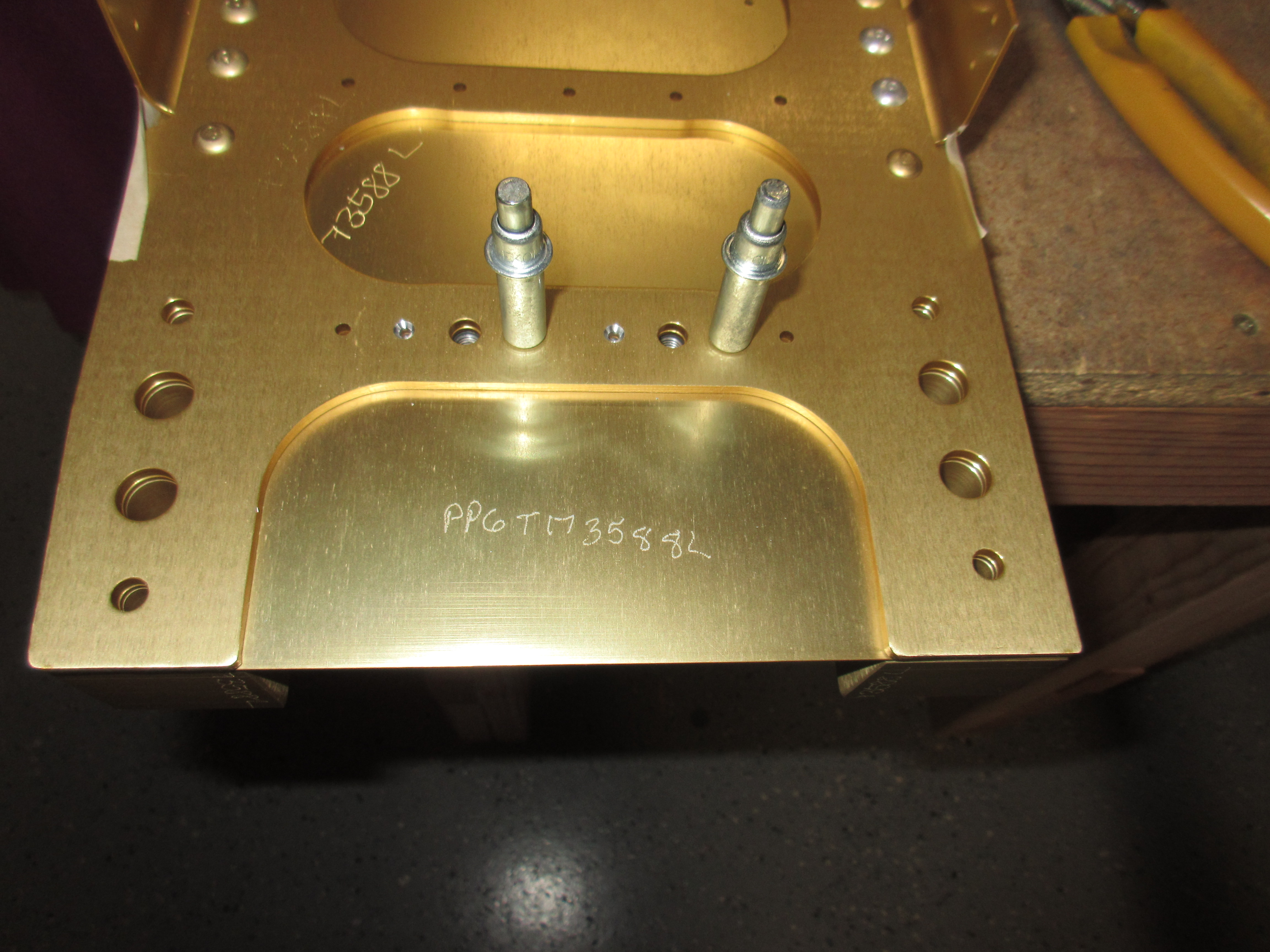
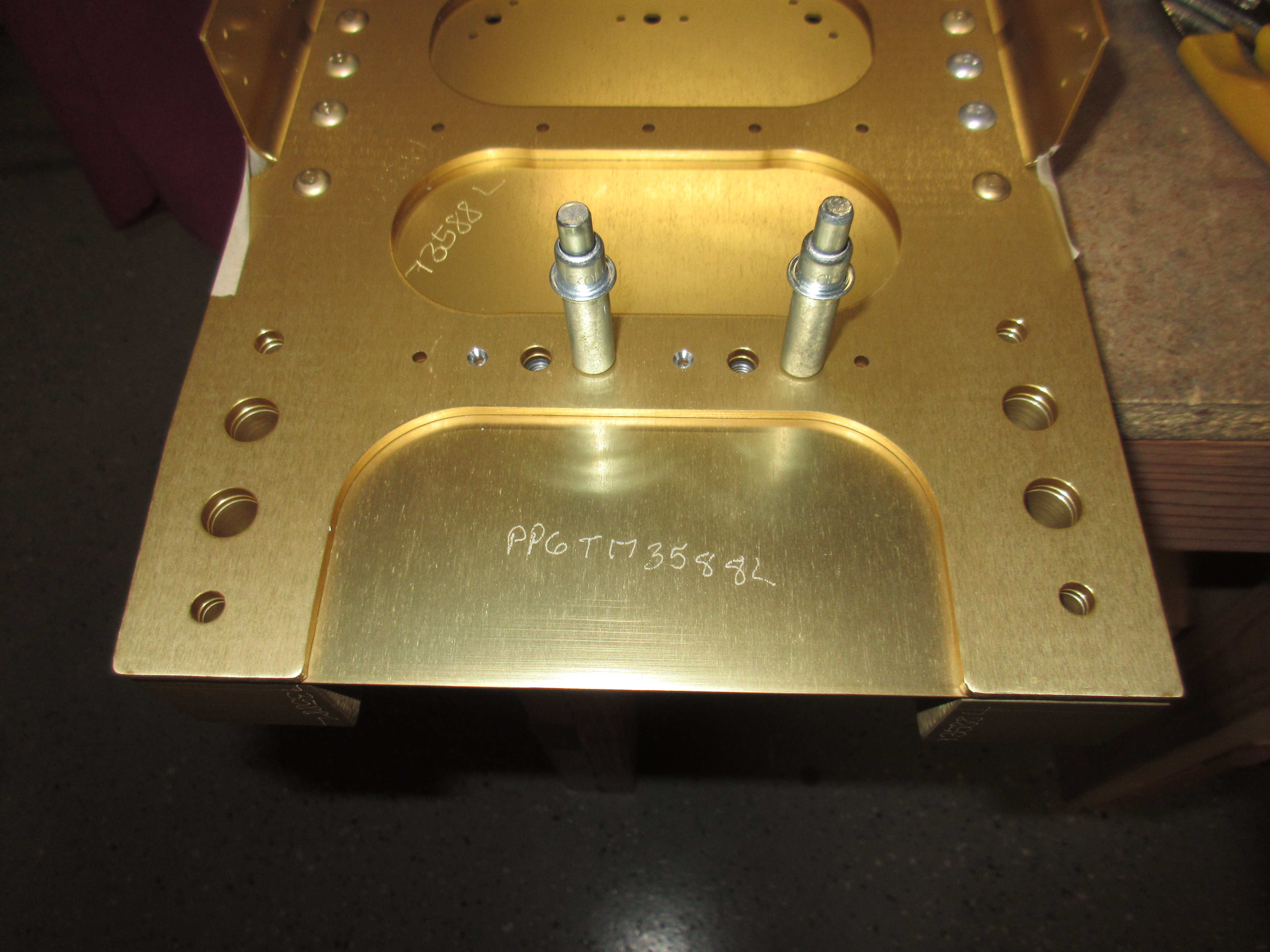
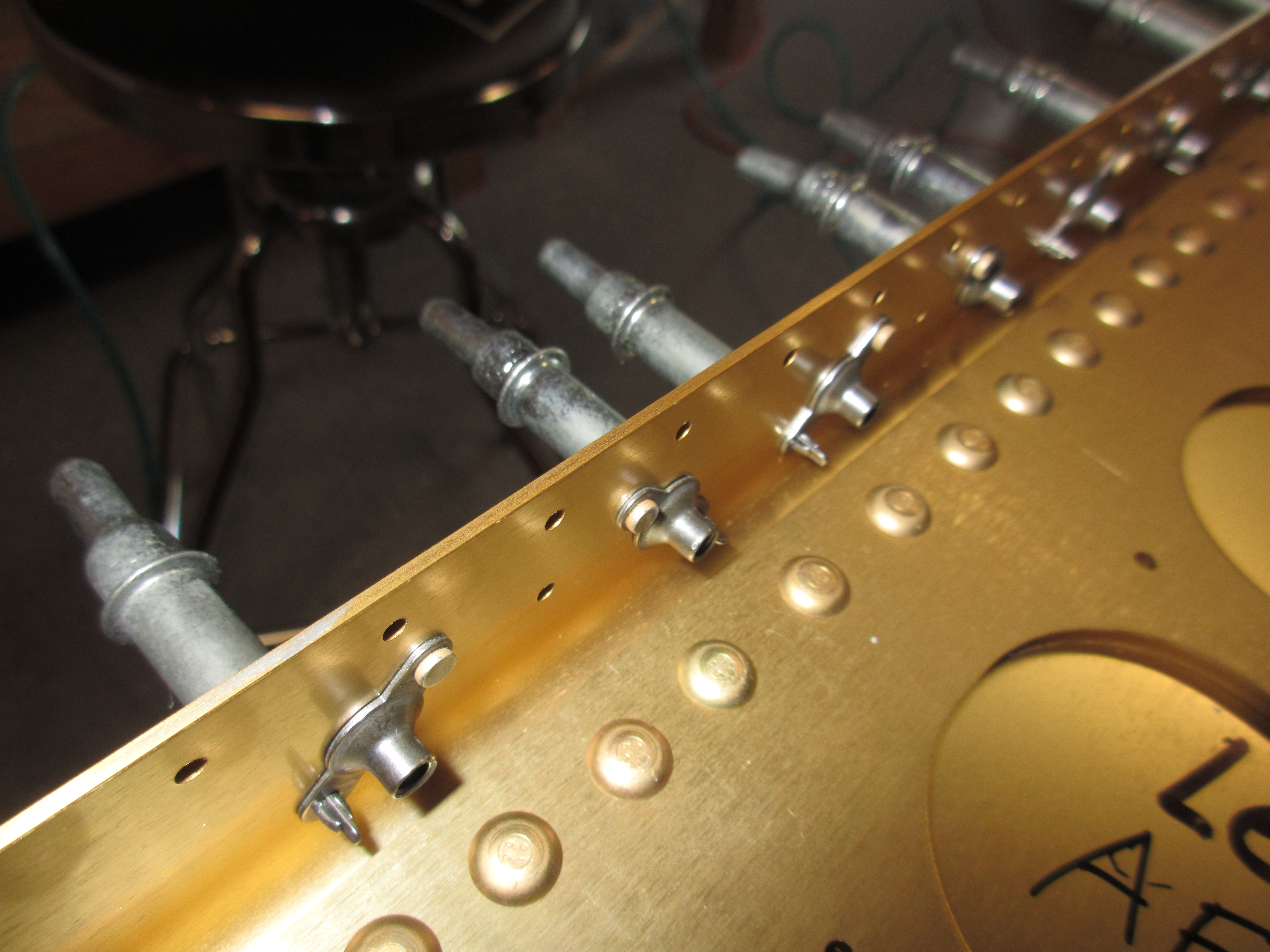
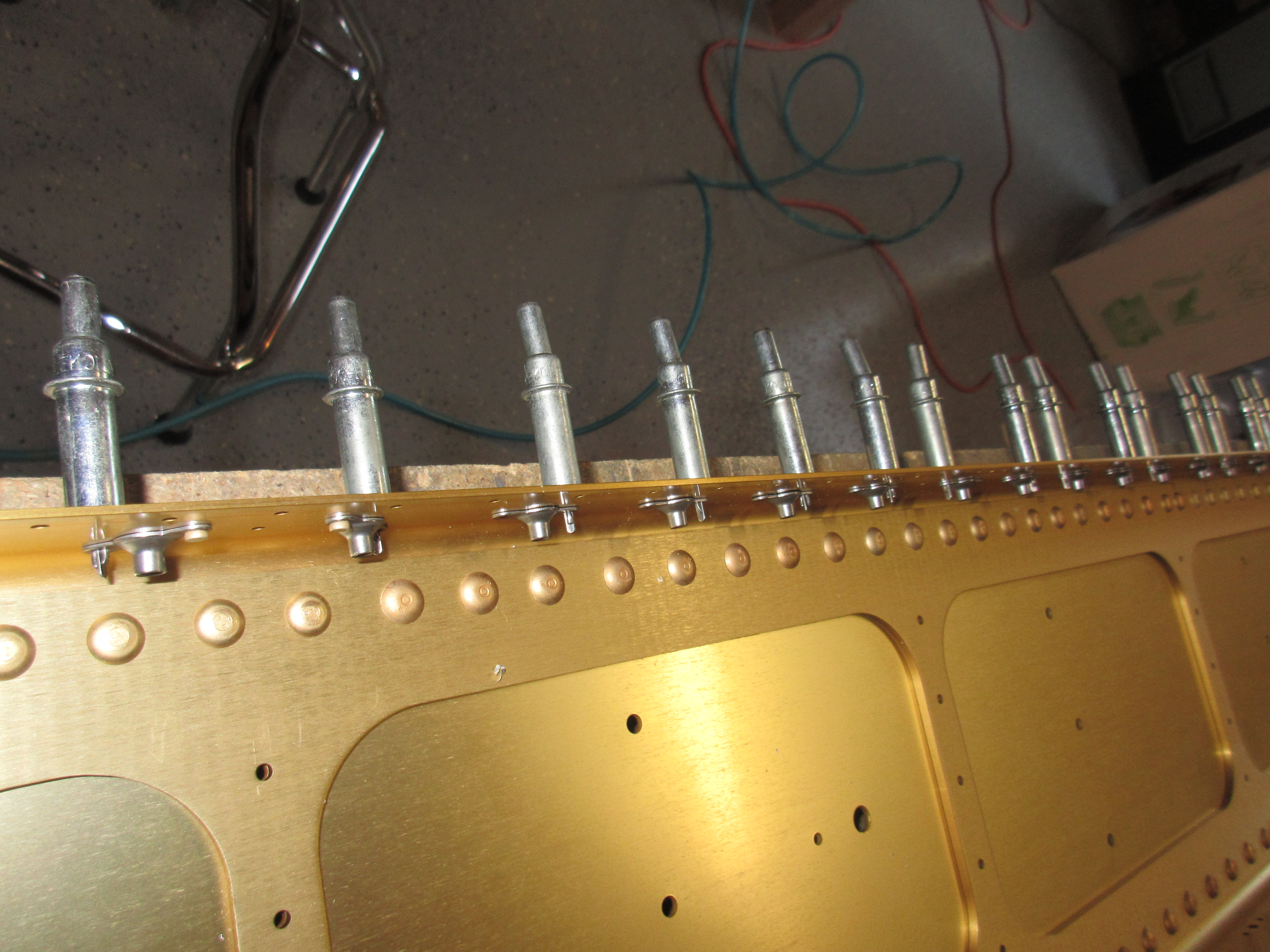
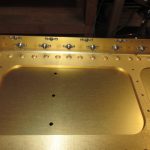
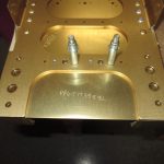
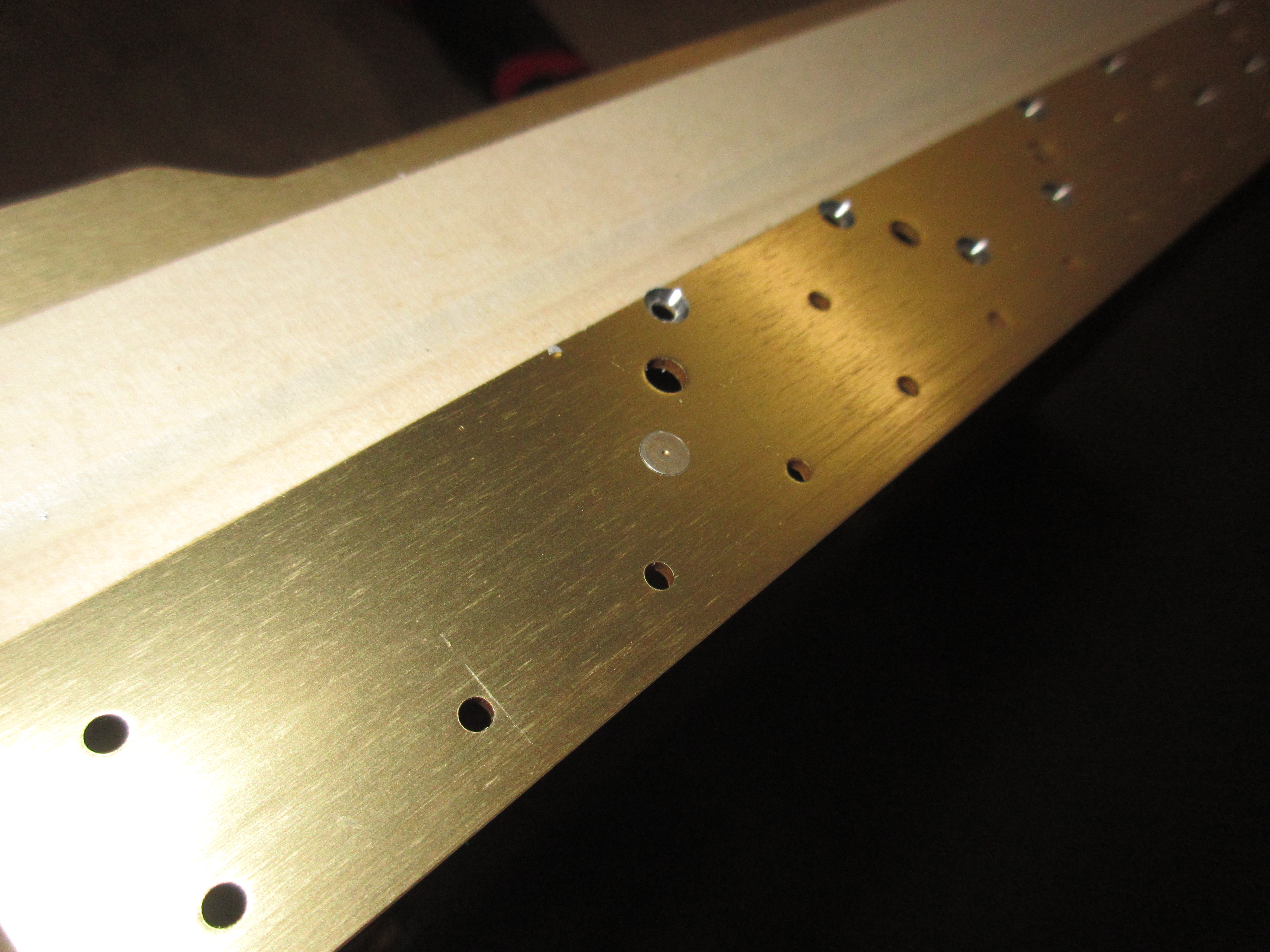
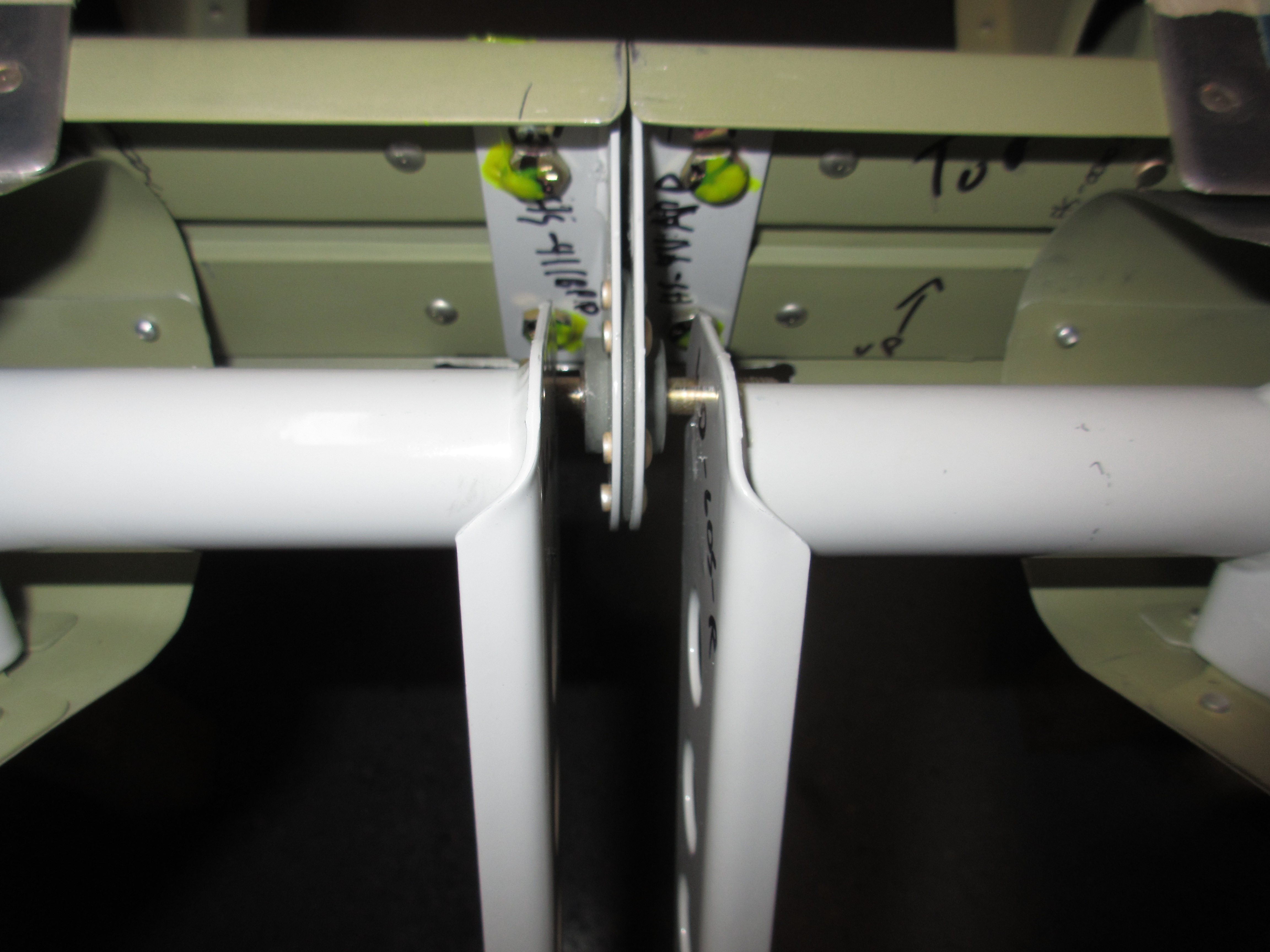
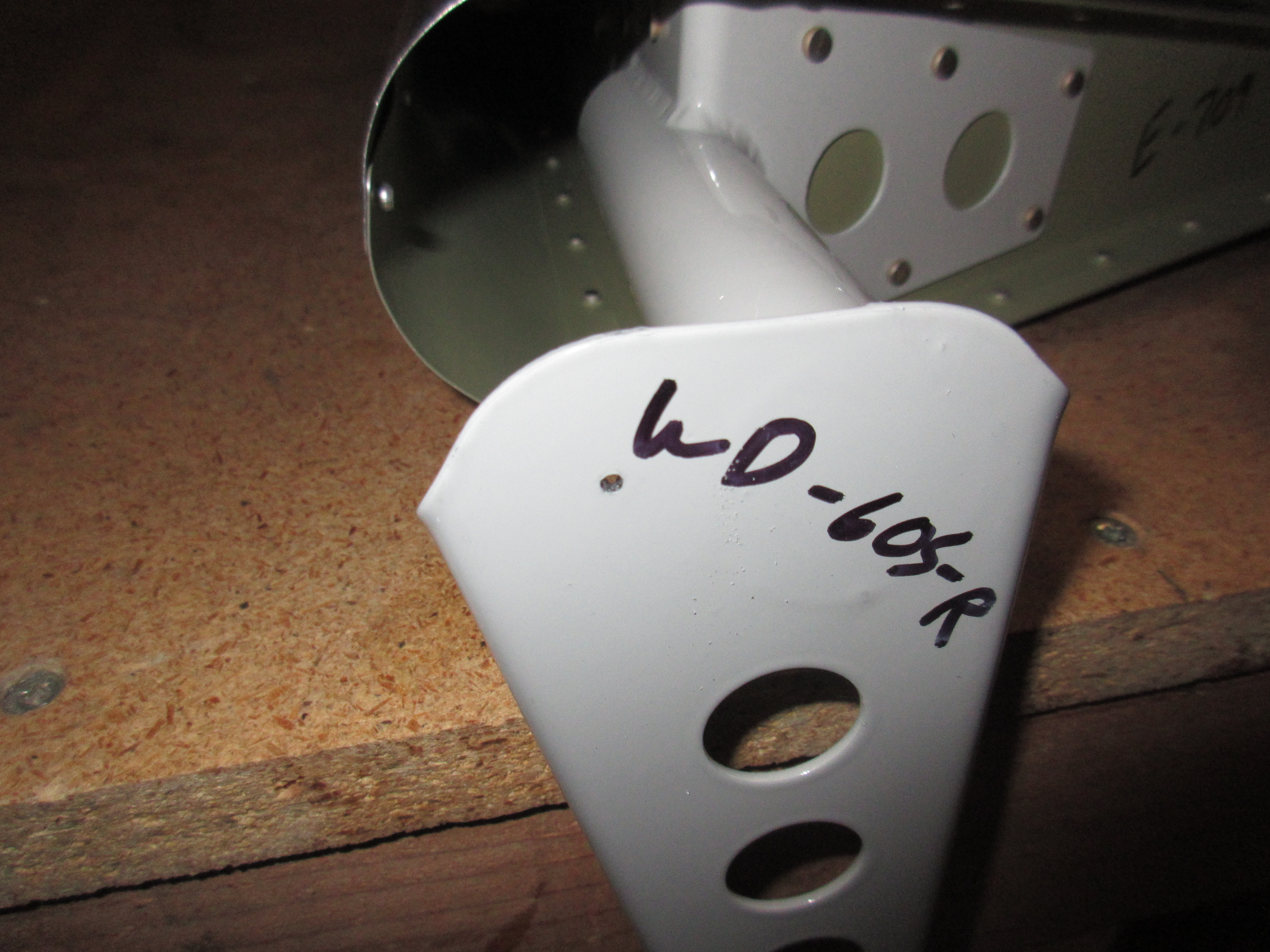
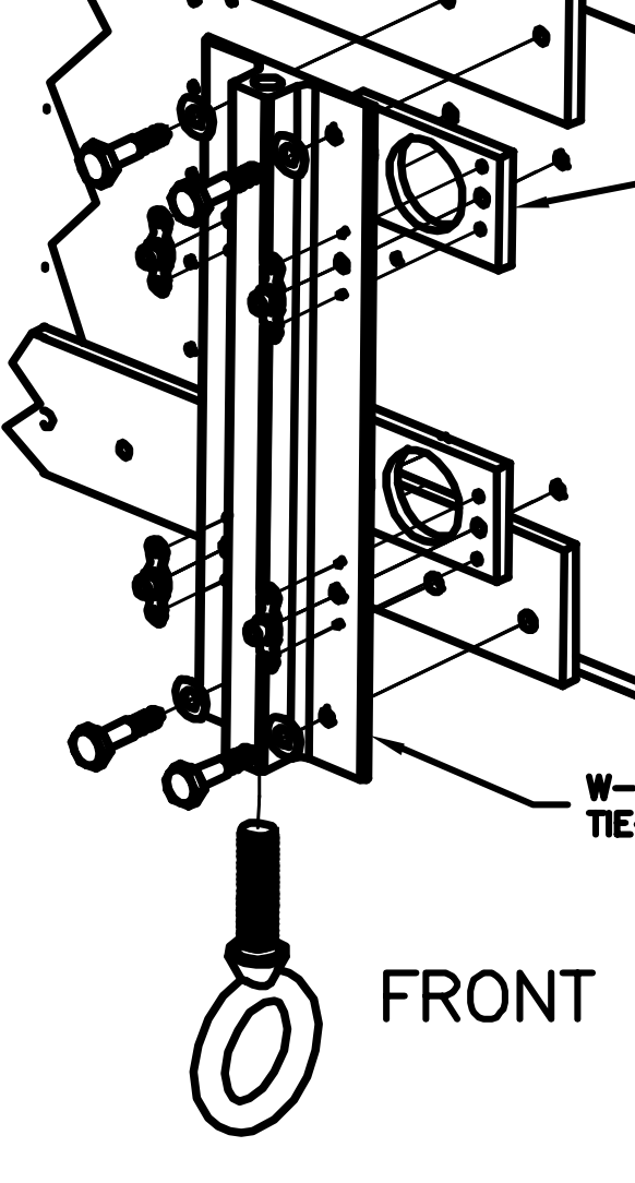
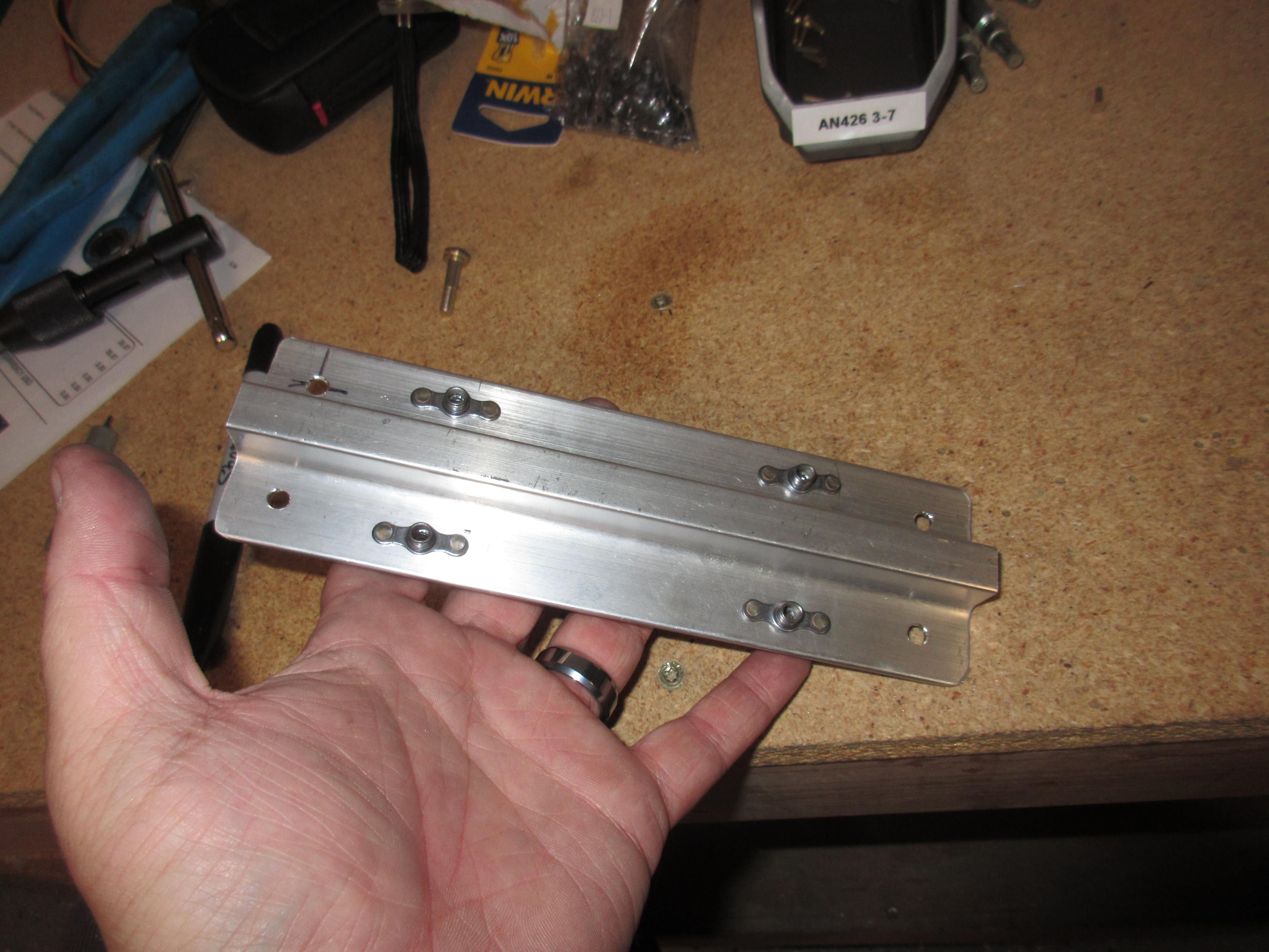
Once I was happy with the left side, I repeated this same process for the right. As I drilled a hole, I would stick a AN3-7 bolt into the holes to make sure nothing moved during drilling.  There is some tight tolerances here, and it holes the aileron bell crank, so its pretty vital this is done right. The next step is to drill for the 4 nutplates that secure the W-726 spacer blocks to the AEX tie down bracket.  This is pretty clever, as Vans has us put the nutplates on the tiedown bracket and then rivet the spacers to the bracket, that way if you never need to replace the nutplate for any reason, its as simple as just removing the entire bracket and replacing it on the bench instead of having to drill the main spar!  See below:

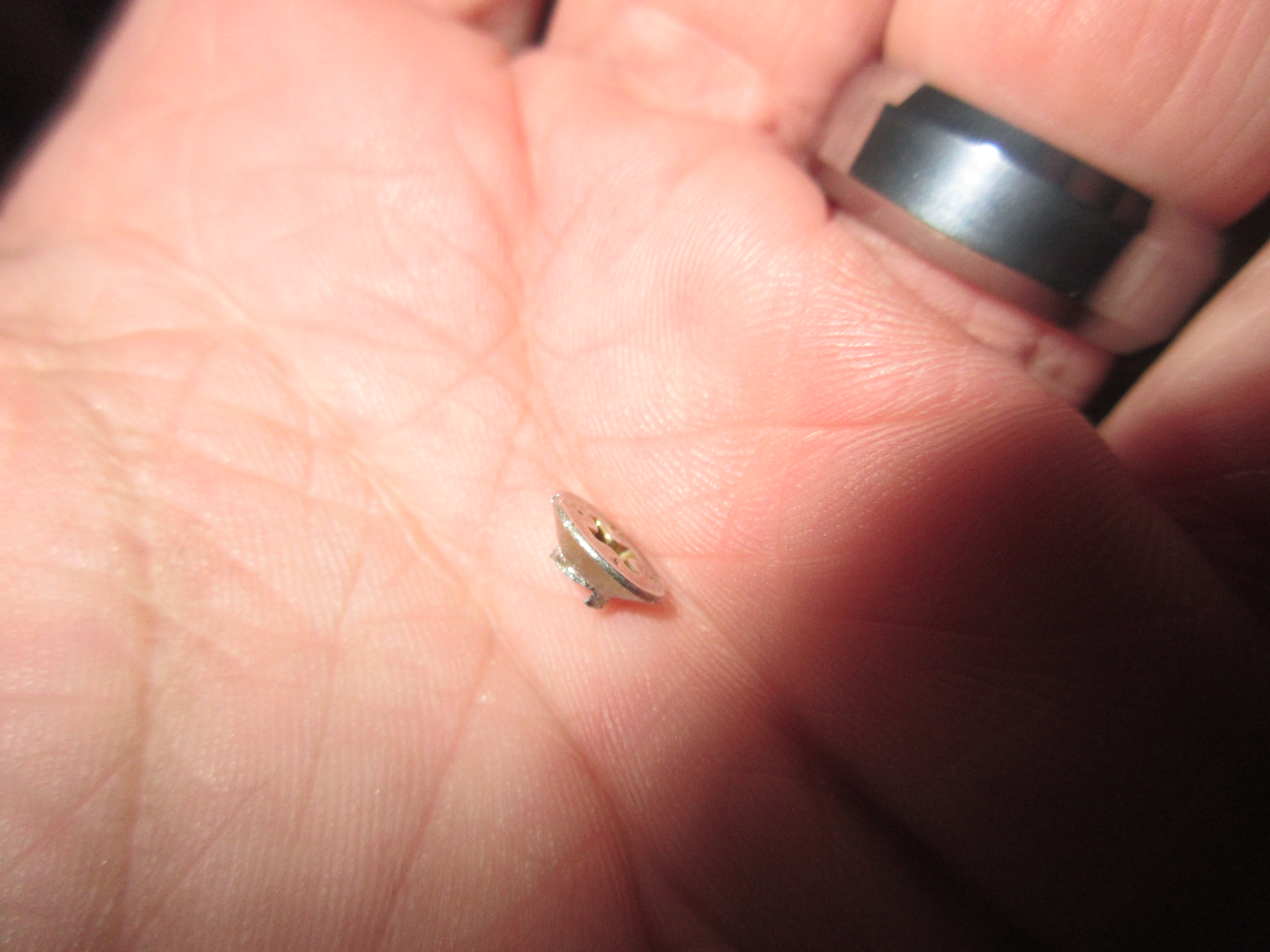
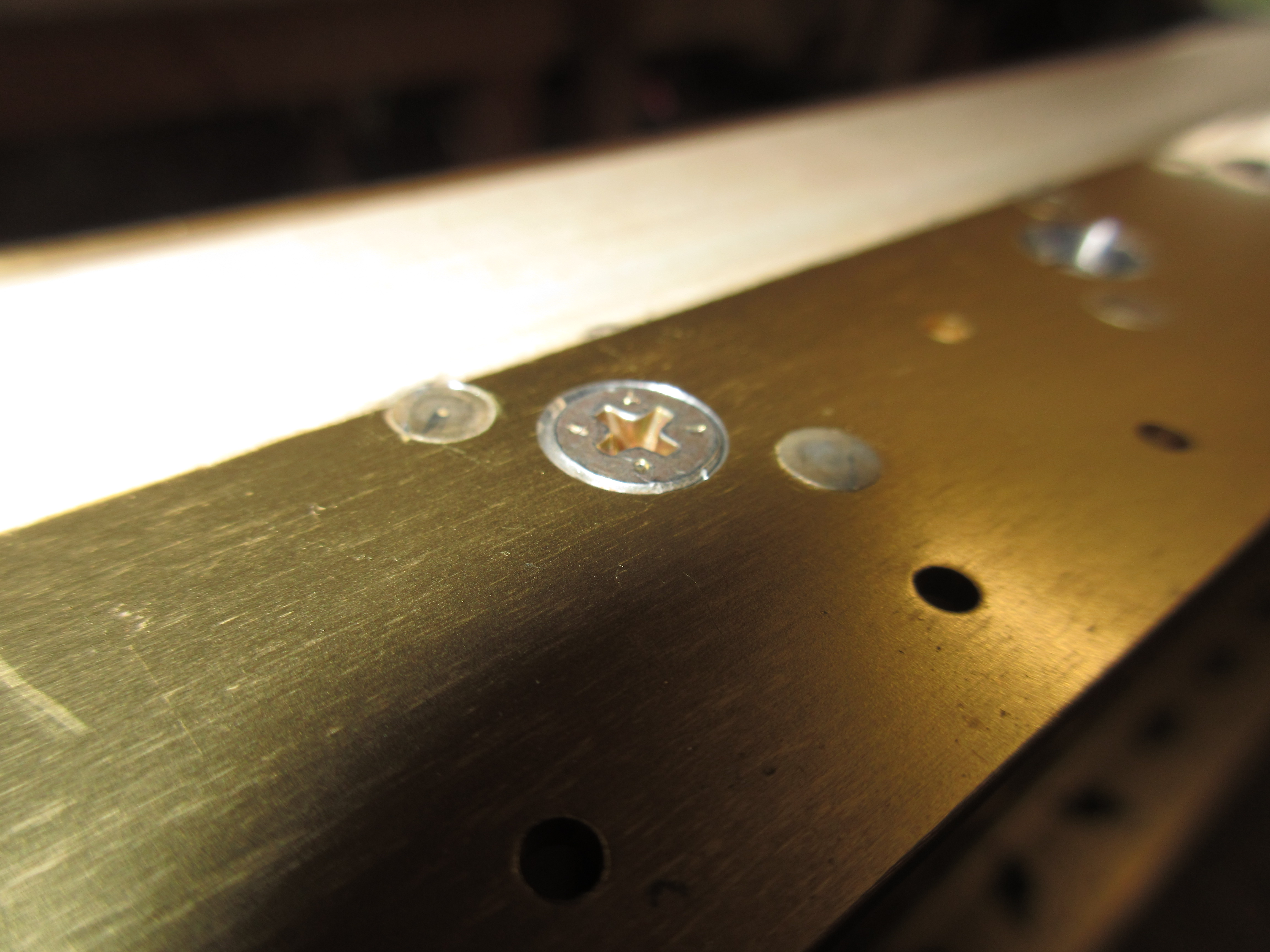
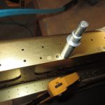
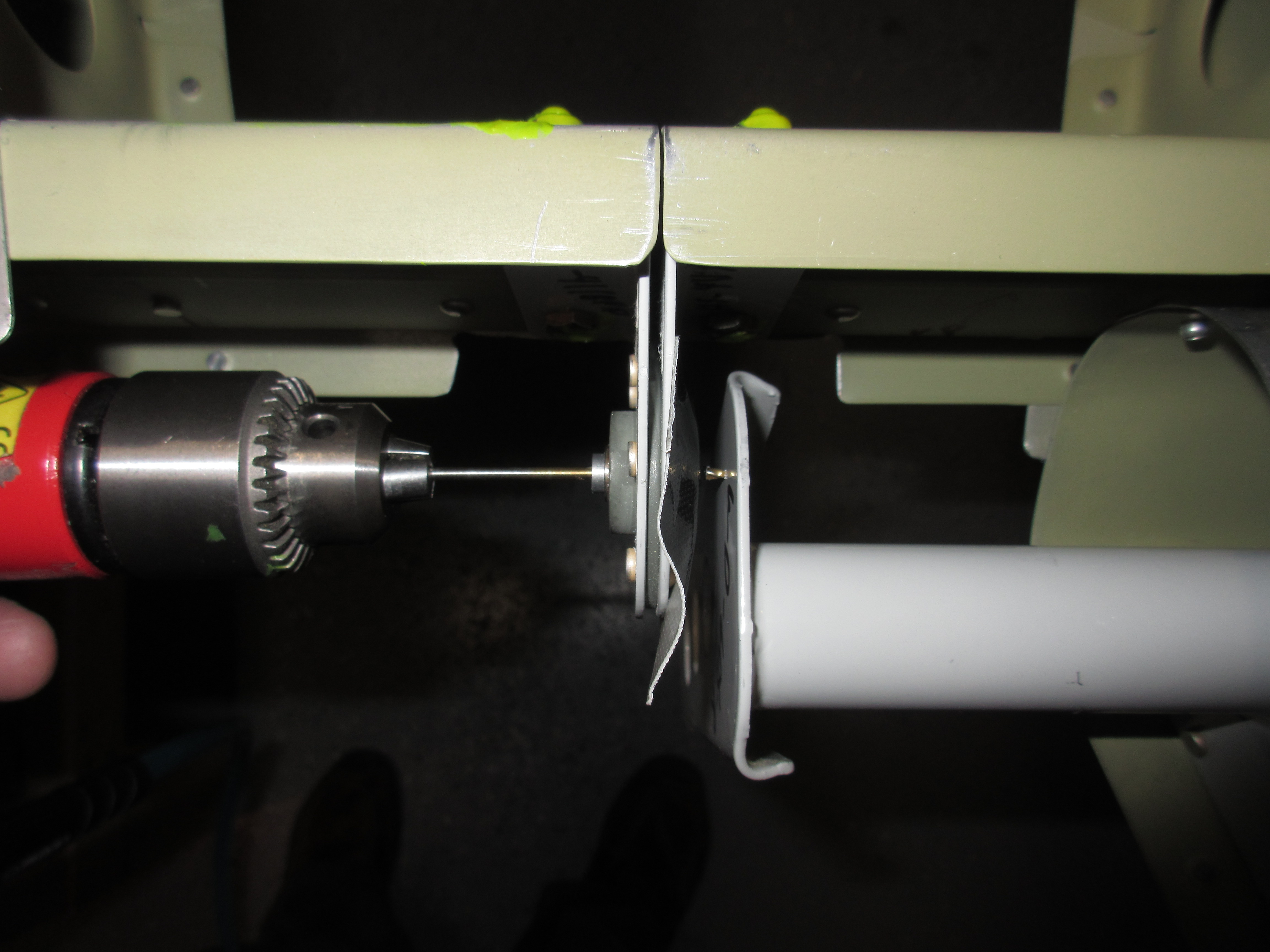
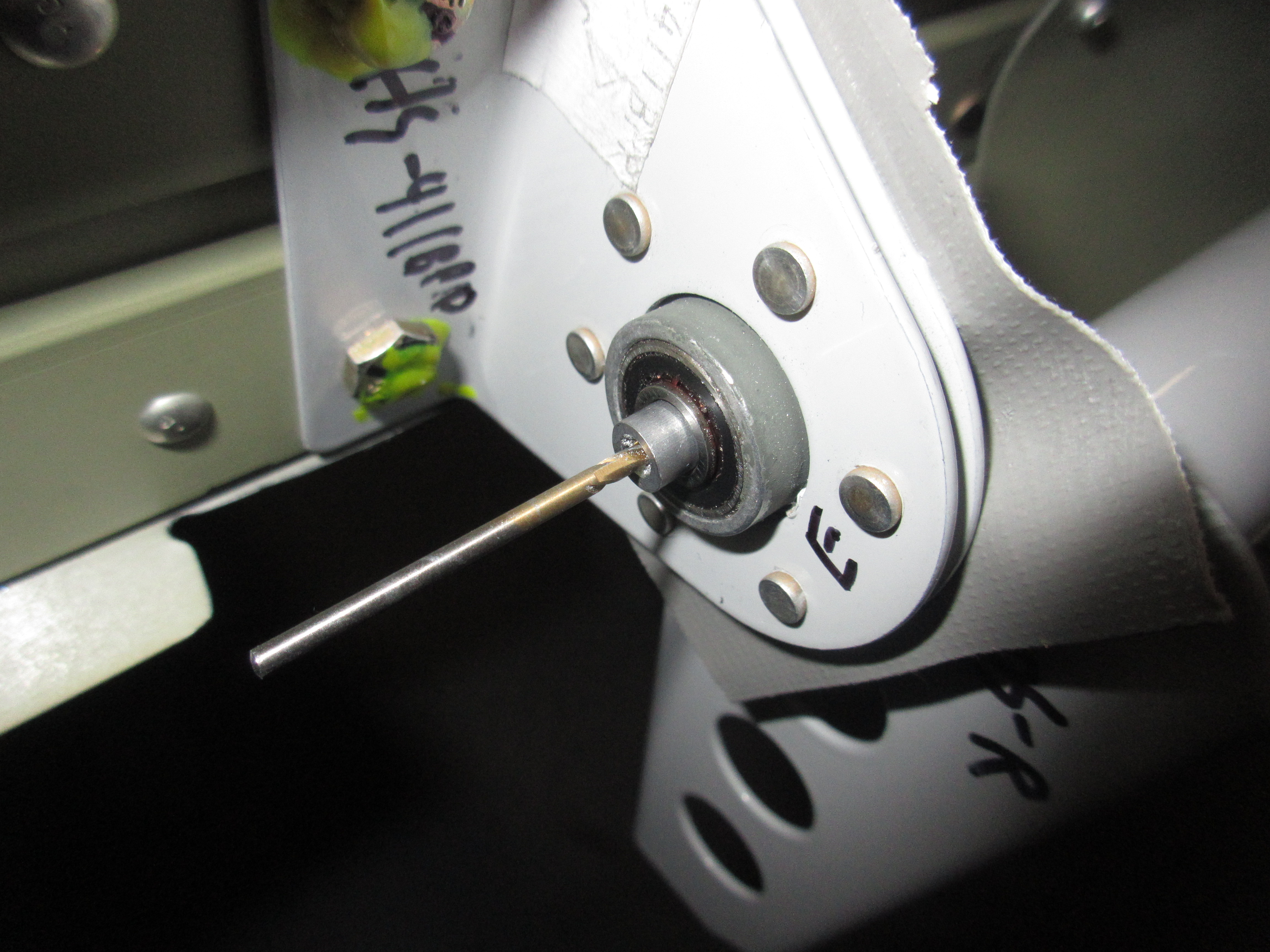
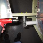
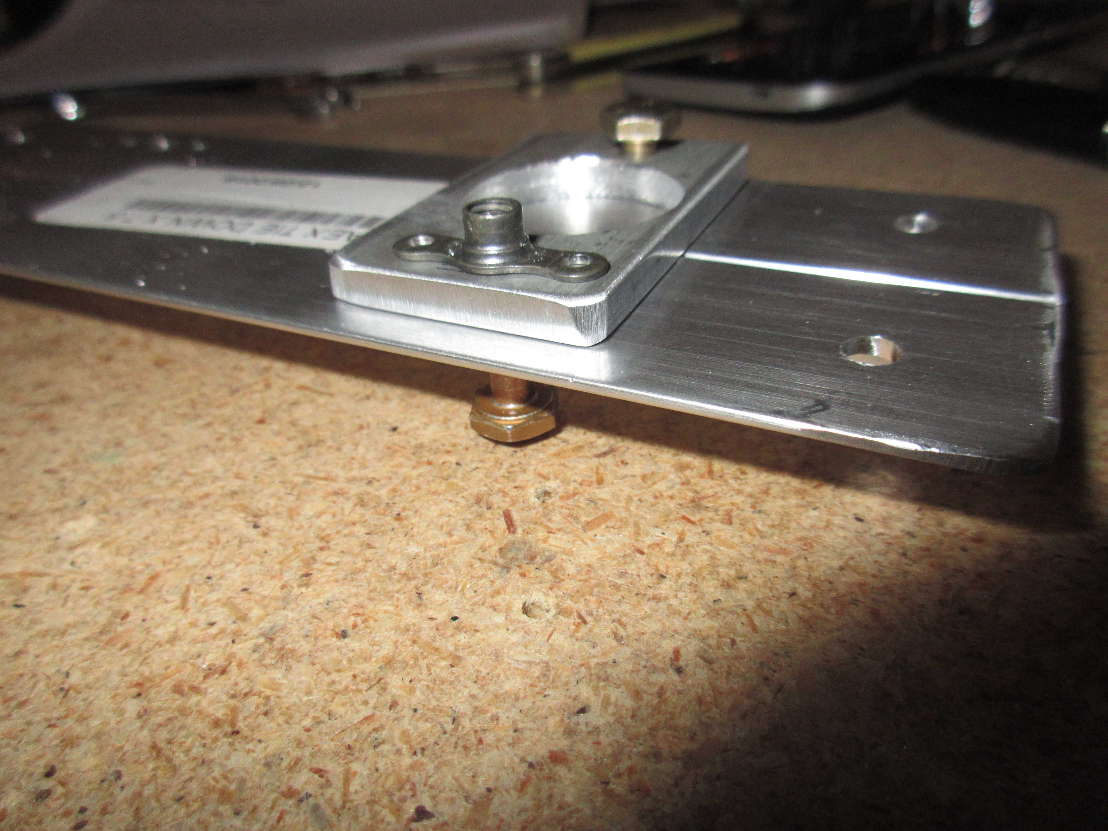
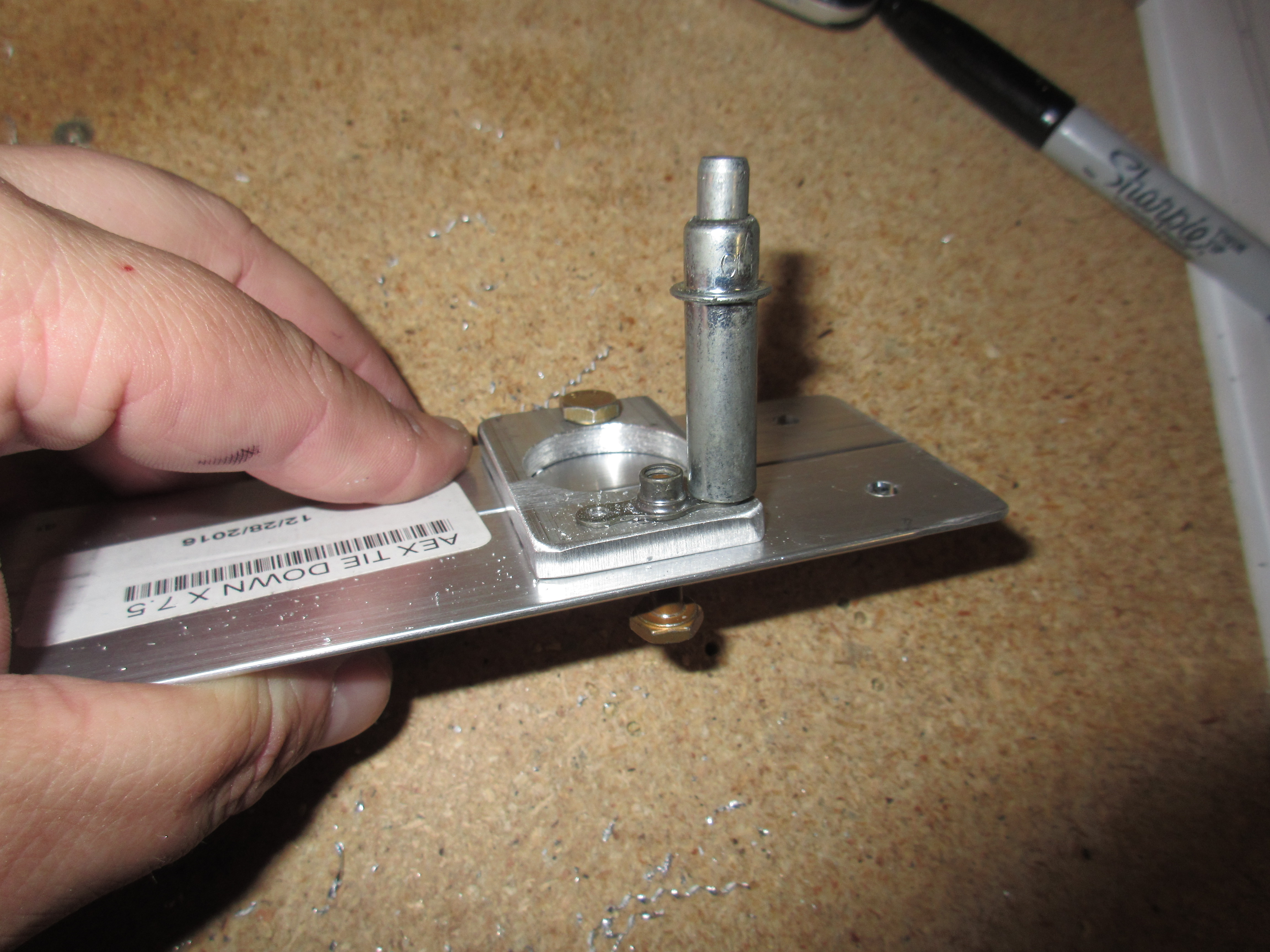
So, theres a couple ways of drilling these nutplates.  The route I chose was simple, and didn’t require any special tools.  I simply took a couple of AN3-6A bolts and ran them into the tiedown bracket and spacers and threaded on a nutplate to use as a jig for my drill holes.  This nutplate would be sacrificial, since its going to drill all 8 of them, but there are extras. Once I drilled the first hole, I clecoed the nutplate and used the bolt and drilled the second hole.

Yes, this nutplate is on backwards, but it doest matter since I am just using it as as drilling jig!!!


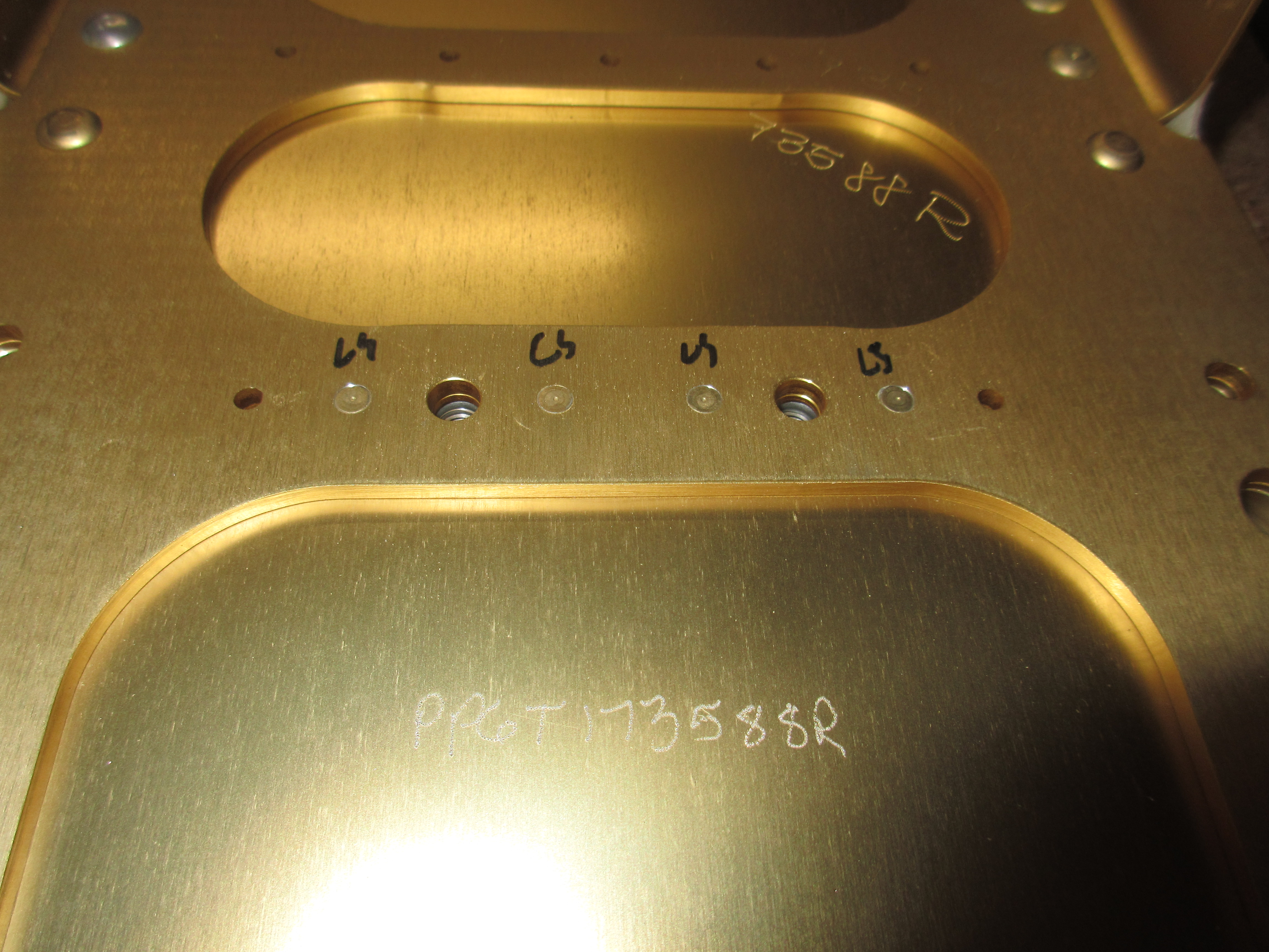
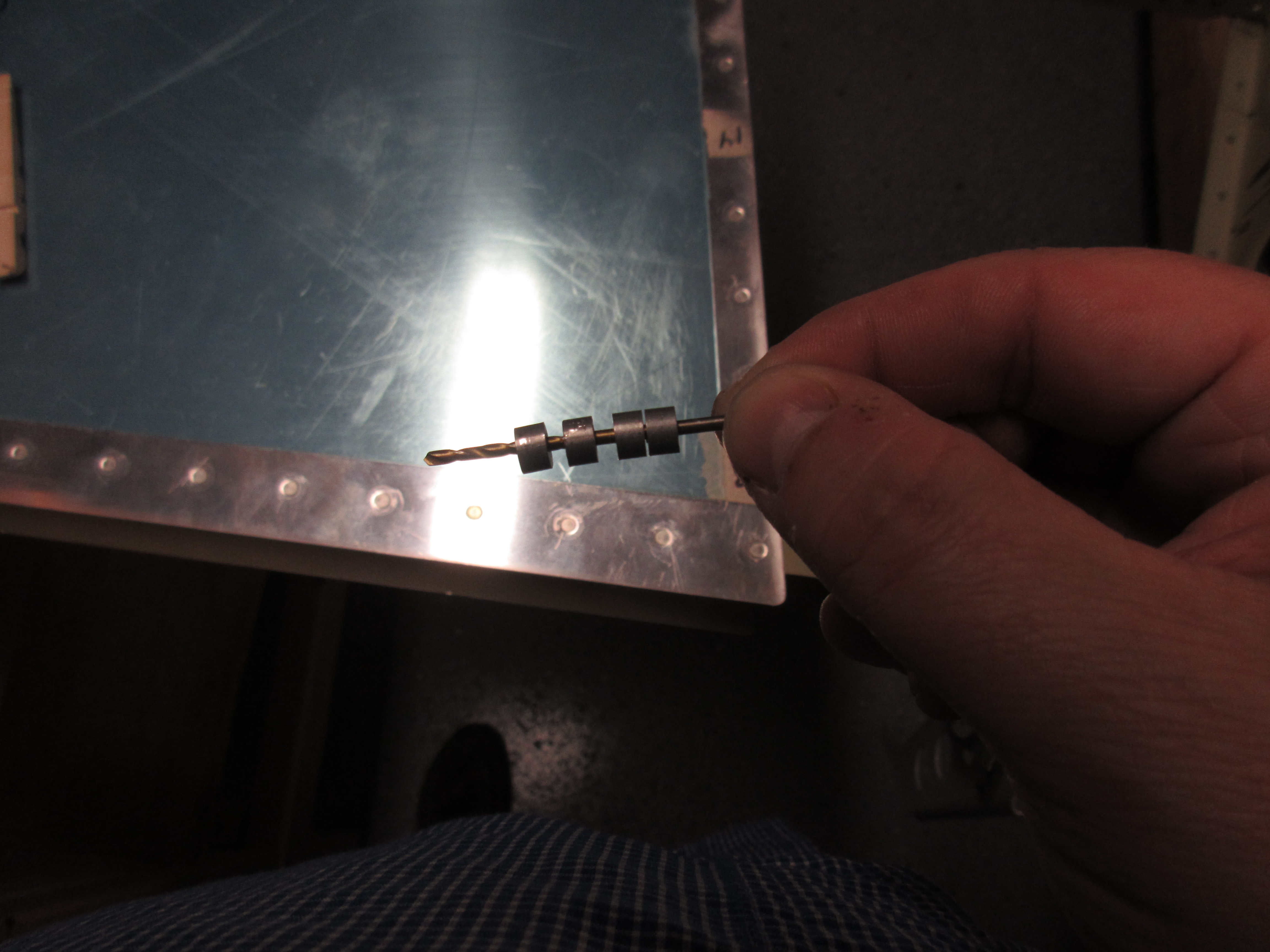
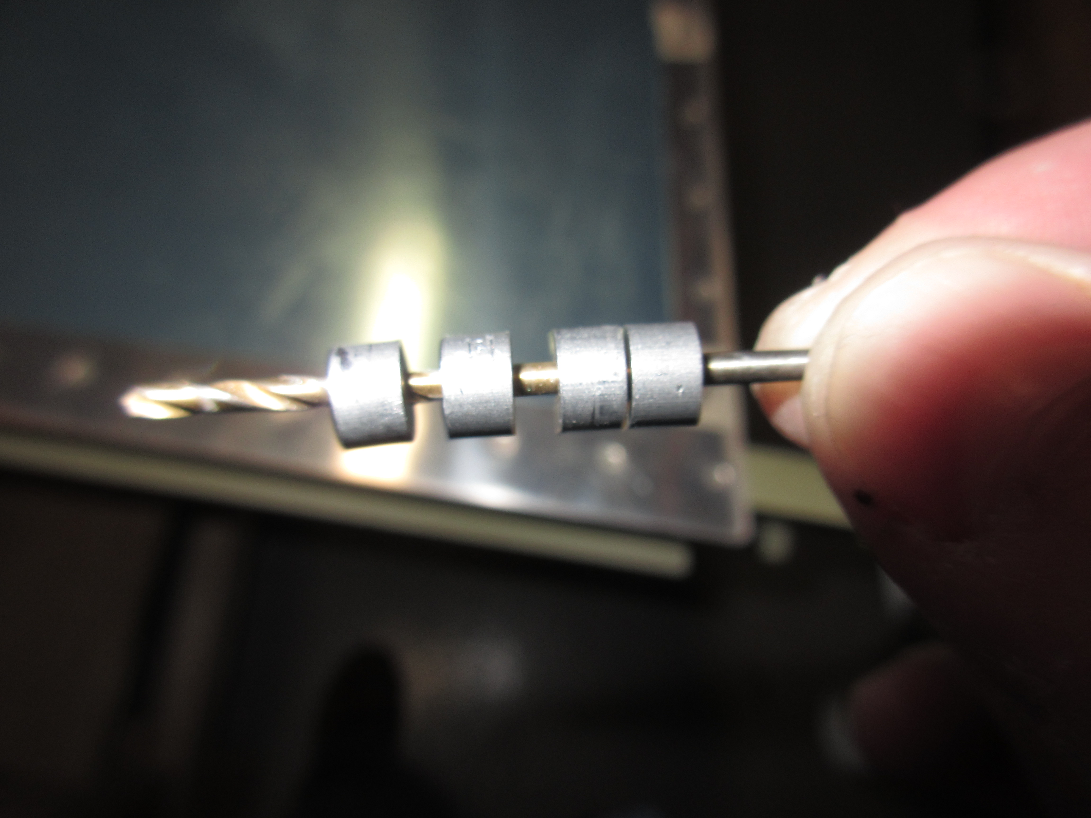
Once all the mounting holes were drilled for the nutplates, it was time to countersink the backs if the W-726 spacers for the flush rivets.  We use flush rivets here because these spacers need to sit flat against the main spar with no interference on this side.  I chucked up my microstop with a #30 pilot countersink and then countersunk all the holes in the spacers.

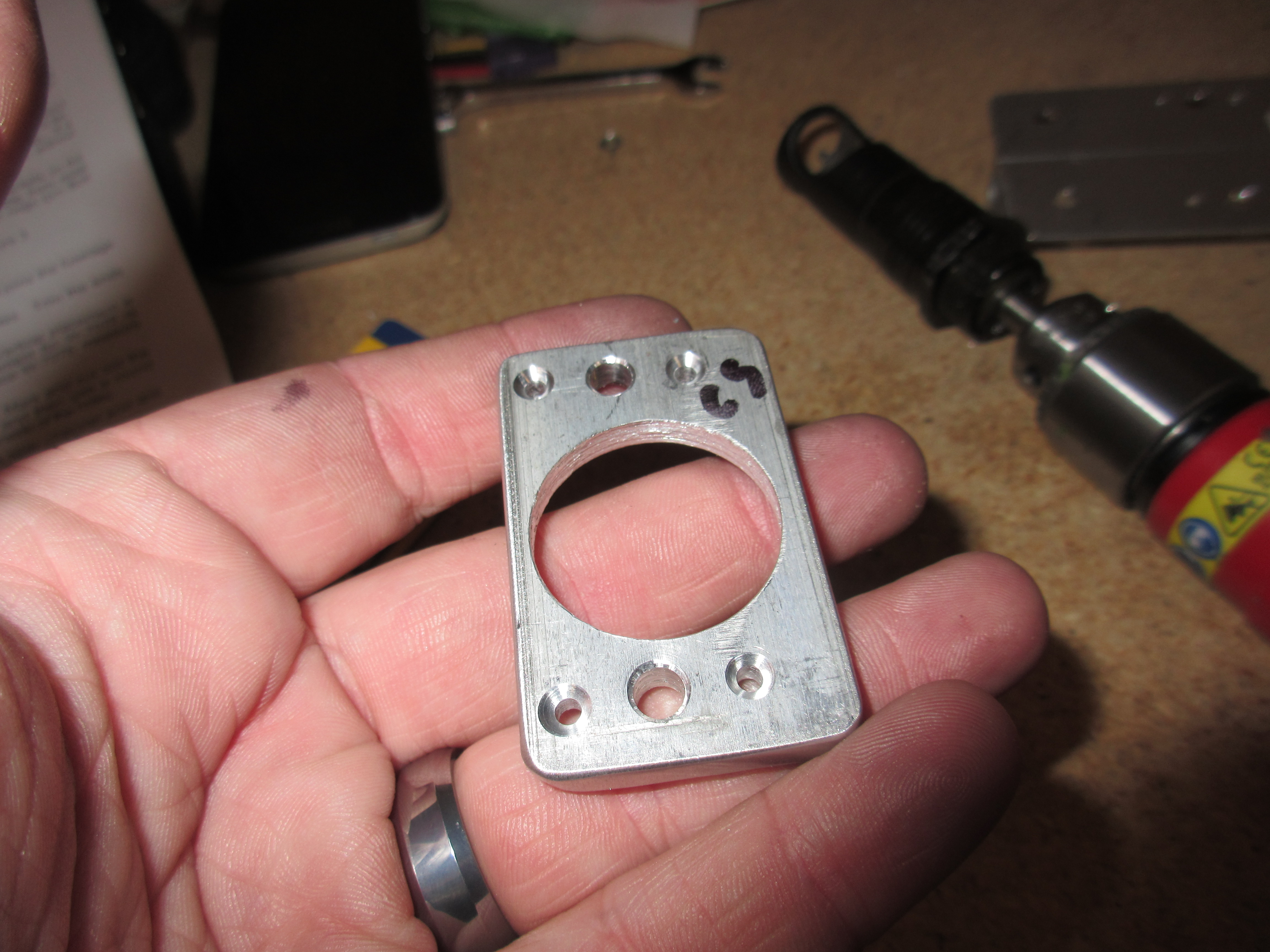
Notice my “CS” marking so I know which side to countersink 🙂

After I had all the holes drilled, it was time to go back and deburr every hole (except for the ones we countersunk, duh!).  I deburred the holes in the tiedown bracket, the spacers and the spars.  I also deburred the edges of the AEX tiedown stock as well and rounded the corners to prevent cuts and scrapes in the future, using the bench grinder and scotchbrite wheel.

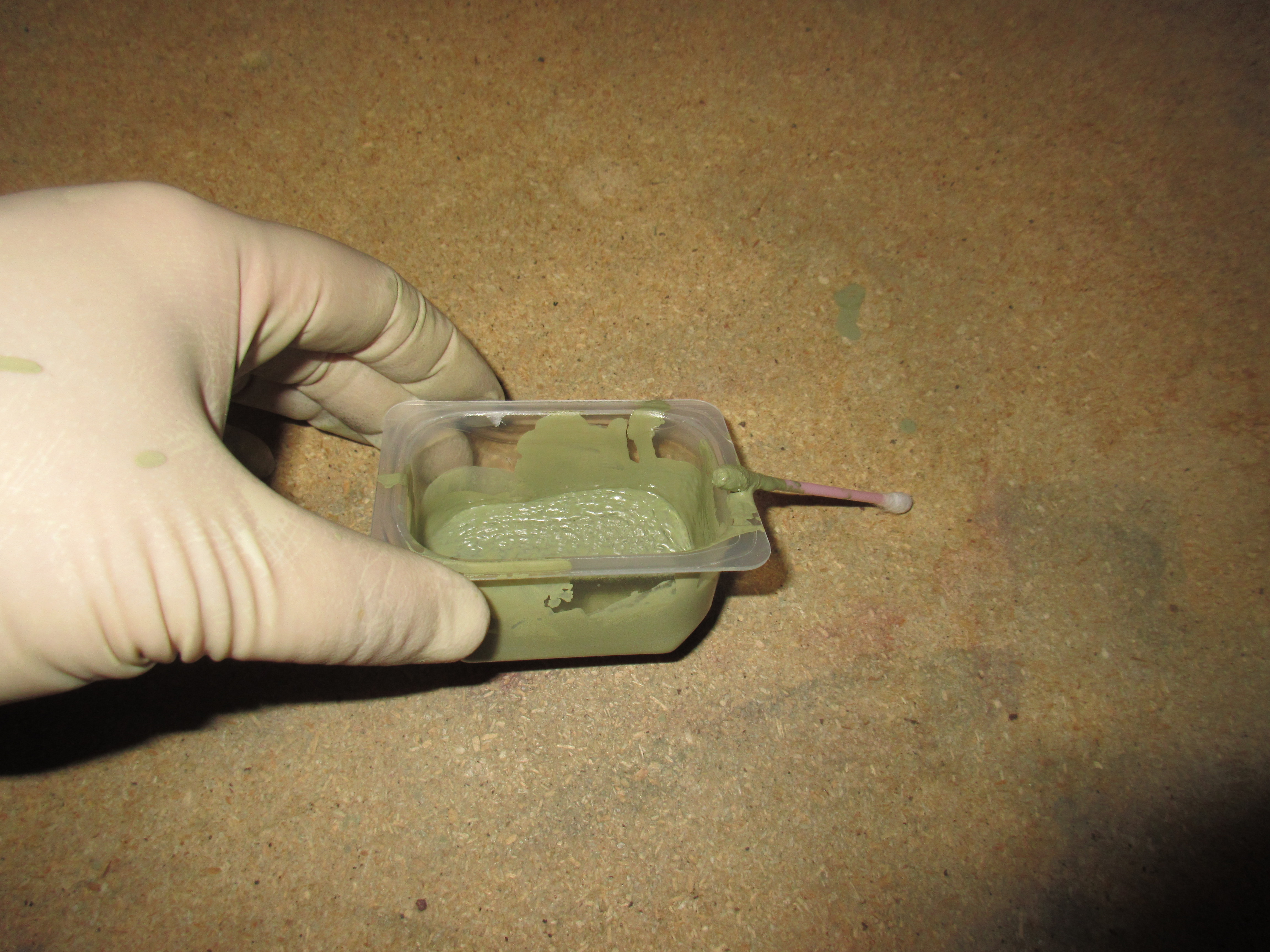
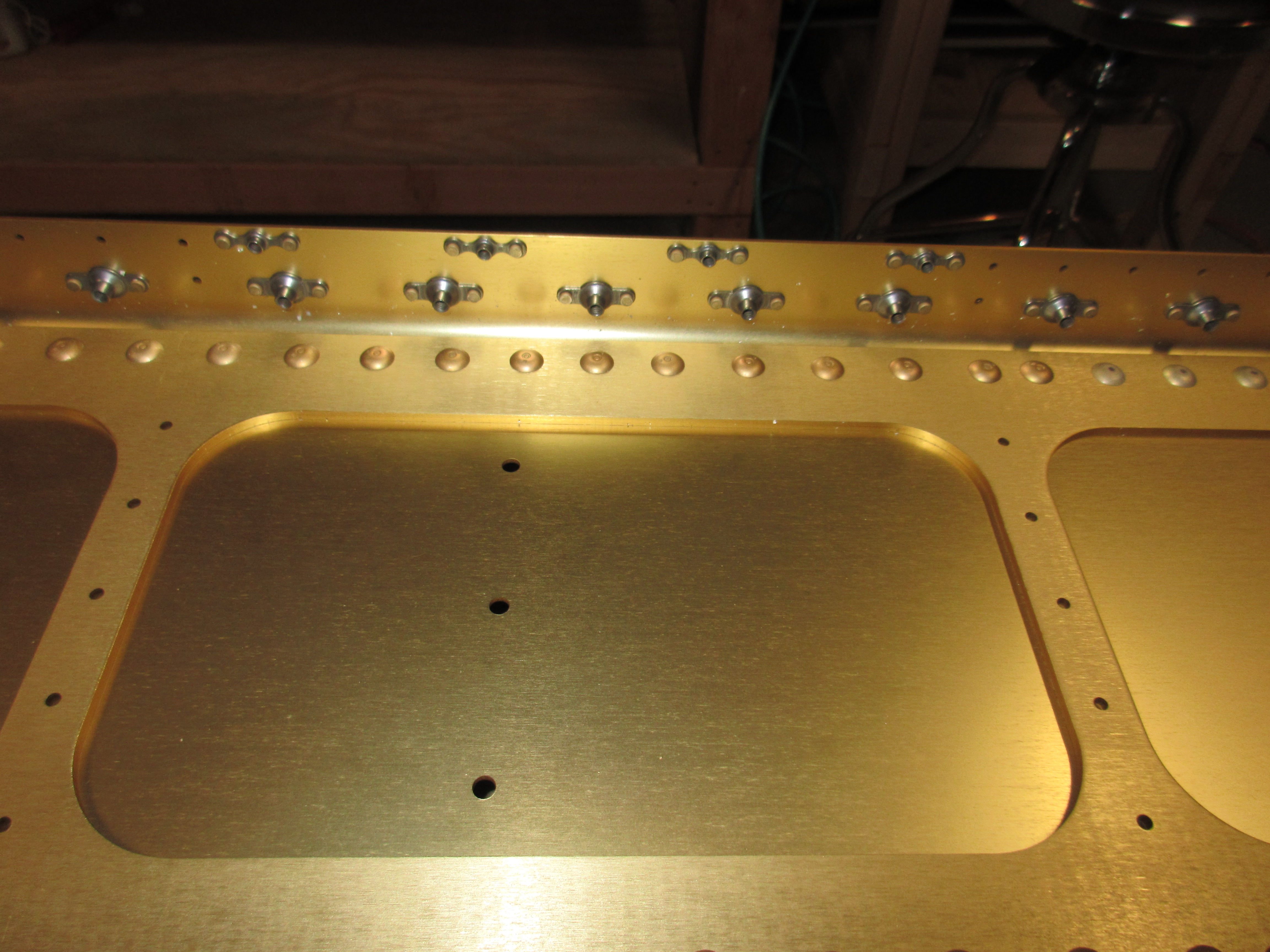
In the plans, Vans tells us to go ahead and rivet these spacers onto the Tiedown brackets but doesn’t mention priming until the very end of this section, where it appears they are talking about priming the entire tiedown assembly (with attached spacers).  I figured these bits of aluminum are both very thick, and will be away from moisture, so I didn’t prime them before riveting them together.  I will, however, prime the entire assembly before I mount it permanently, just to be safe. That will only leave the two surfaces of aluminum that are riveted together (facing each other) not primed.  I think it will be alright.

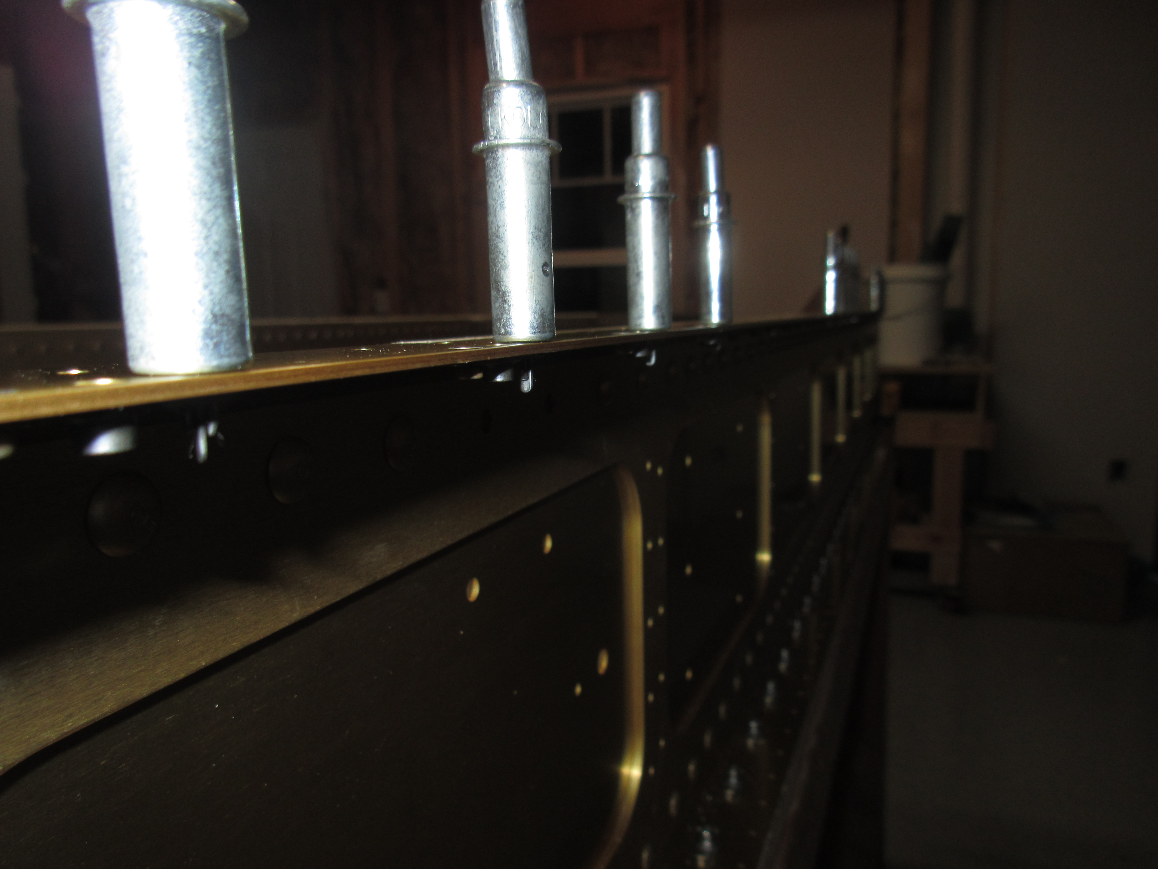
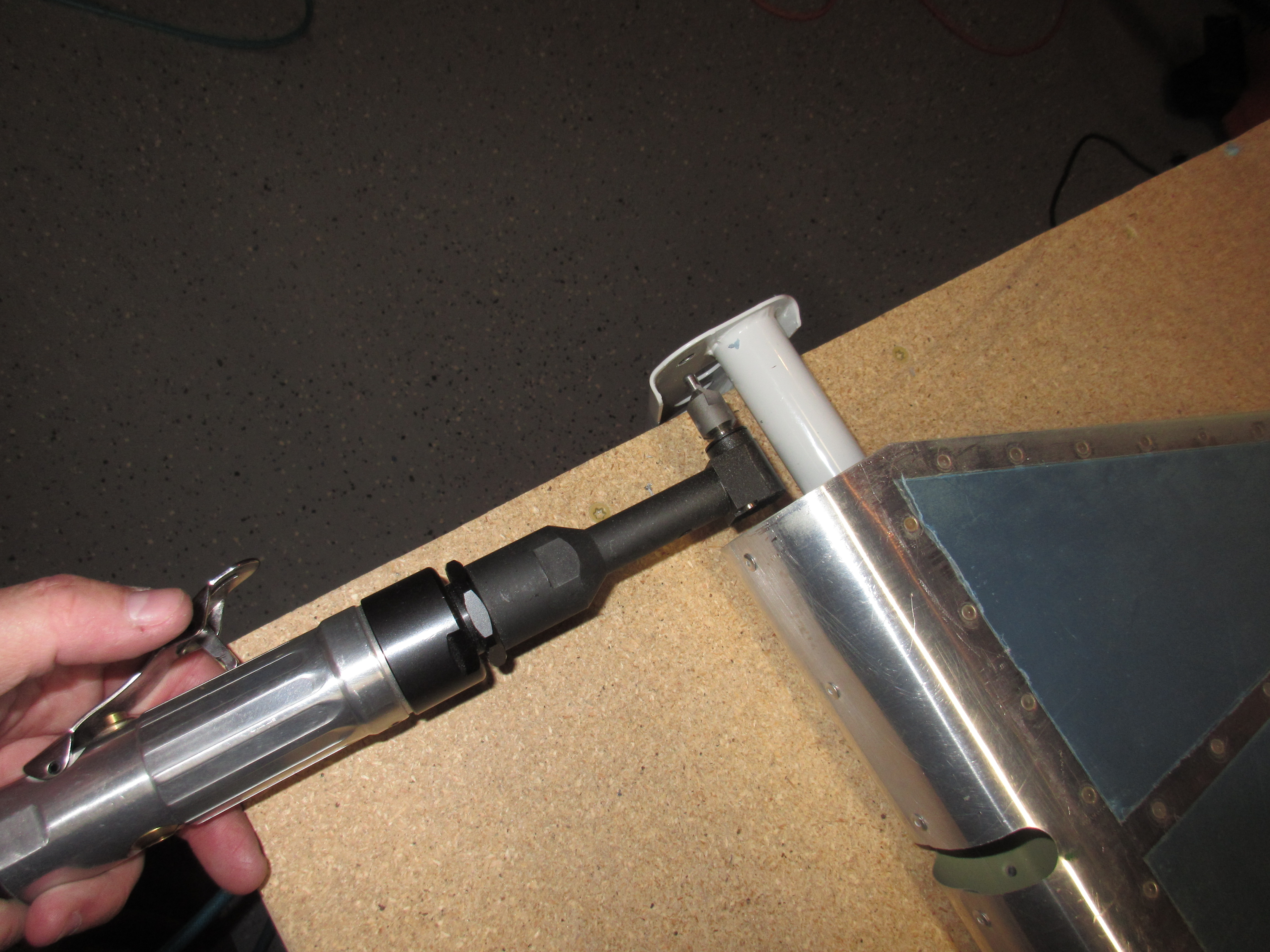
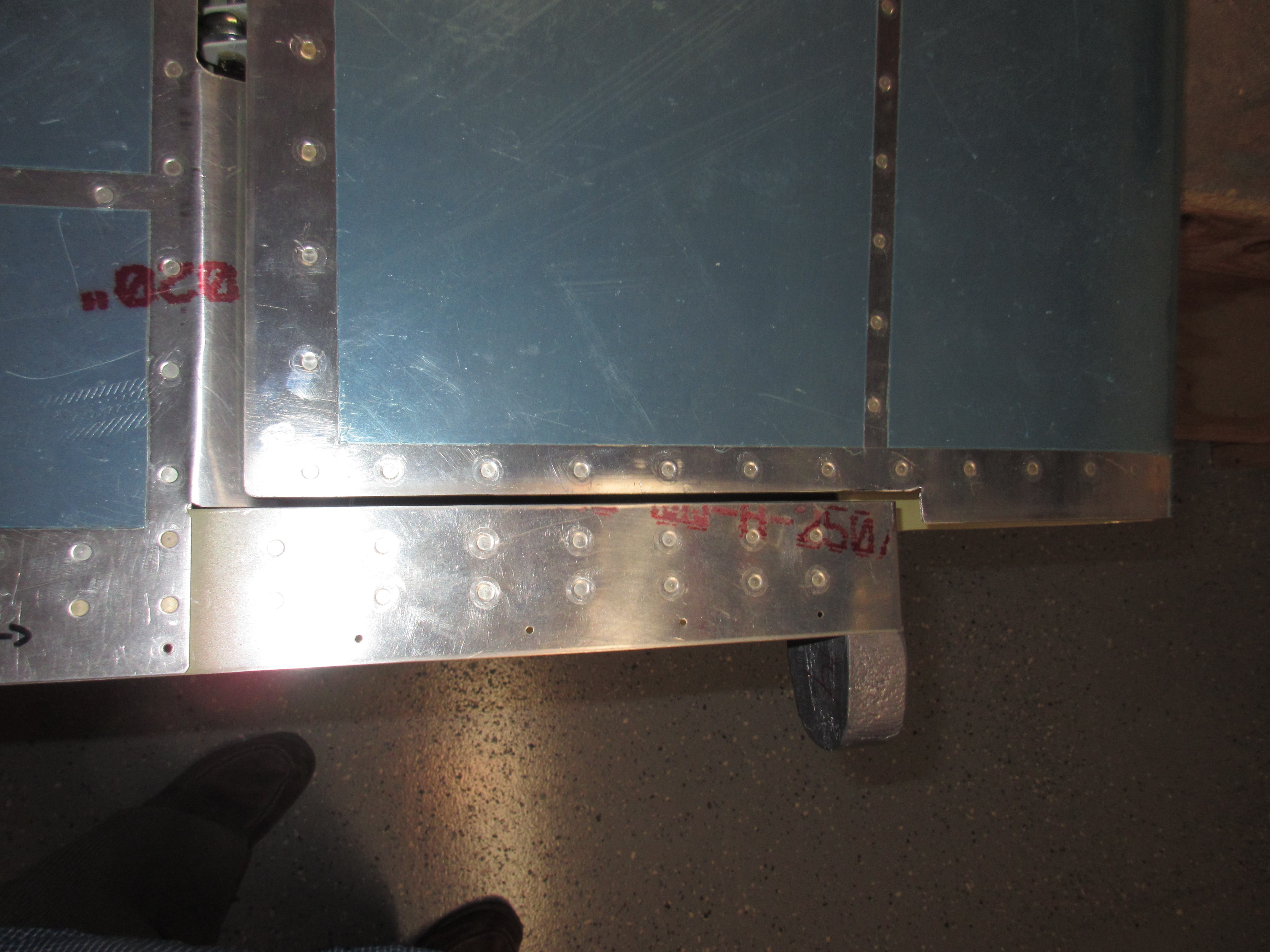
Riveting these together is your standard procedure for nutplates.  Cleco one side, rivet the other and repeat across all the other nutplates.  I used a squeezer because why not?  They turned out great!

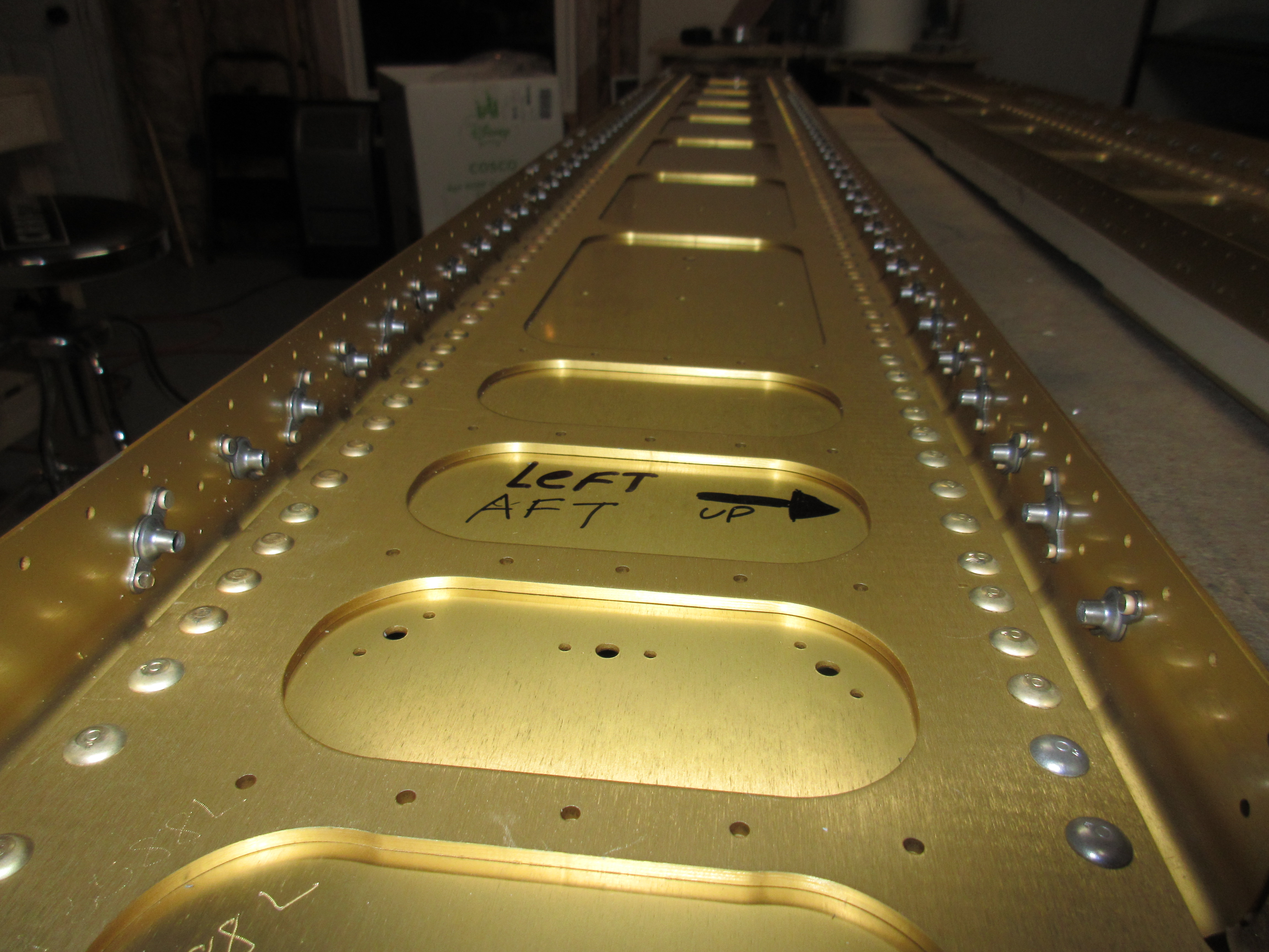
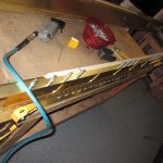
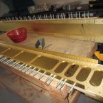
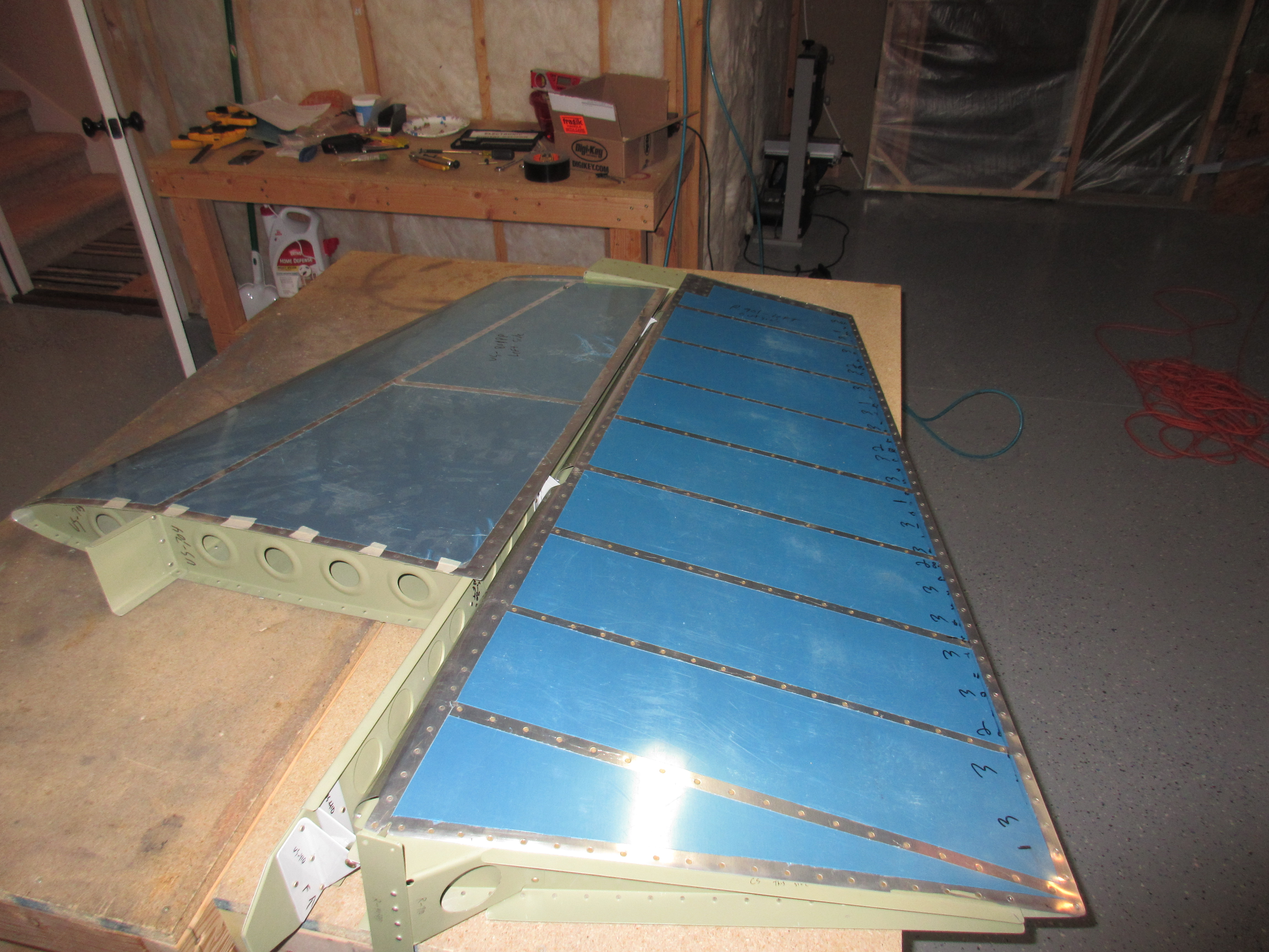
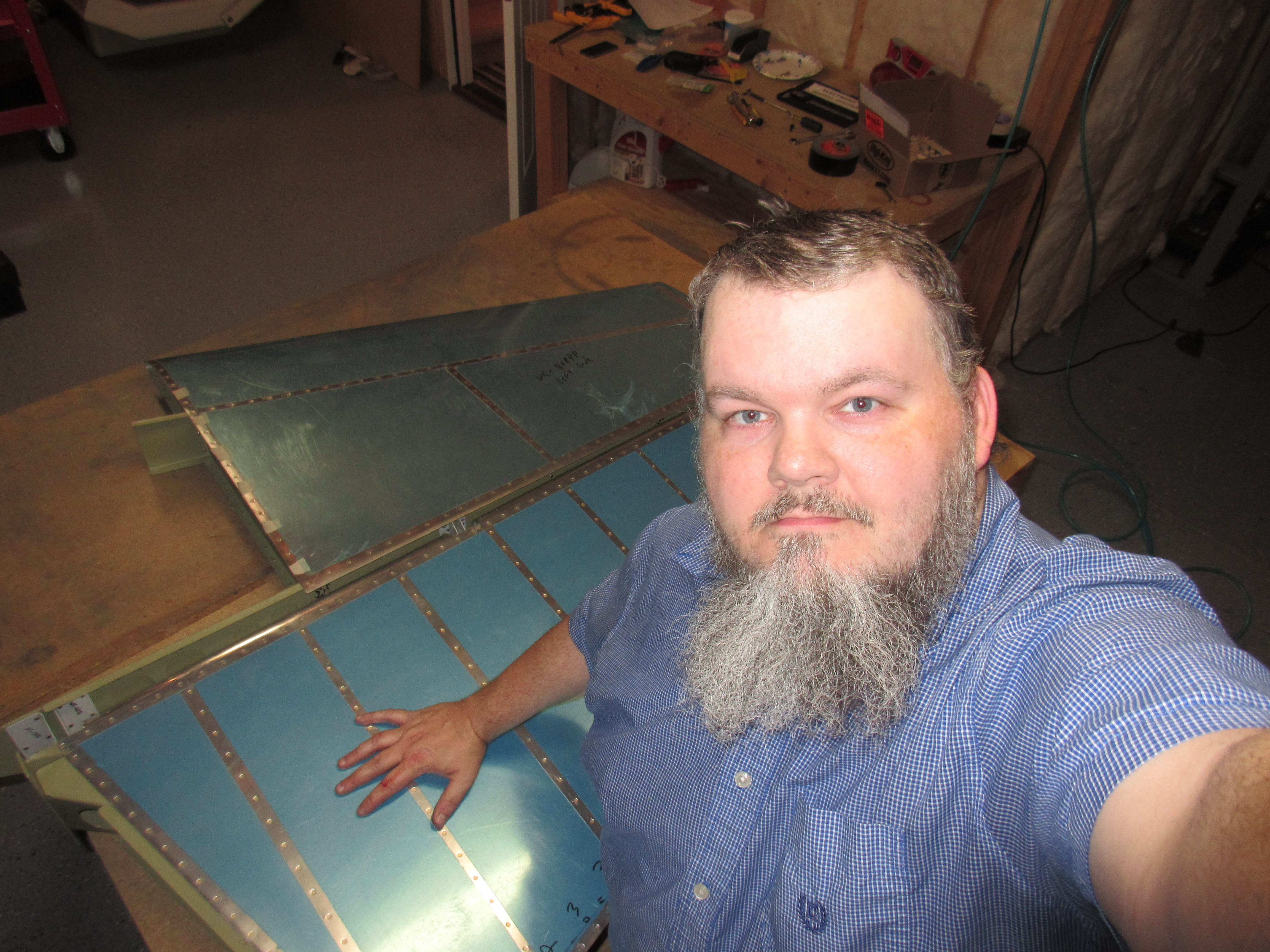
Completing both of these tiedown assemblies to this point was about 4 hours or more of work, so I called it a night.  I’ll drill the hole for the stall warner tomorrow, and may even go ahead and prime these.  I am going to go with a Dynon panel, so I will need to order the servo mounting kit because in one wing, the servo attaches to the aileron bellcrank, which then bolts to this tiedown bracket. I’ll get that on its way this week, and a few other odds and ends as well. Here’s all the photos from tonight:

Google Photos Link: https://goo.gl/photos/sPF5MJKnv1kmqRoZ6

Hours Worked: 4.25

Countersinking Nutplate Screw Holes

I was able to wrap up all of the fuel tank attachment nutplates and the inspection cover nutplates tonight.  In the last session, I installed all of the nutplates, and tonight I finished them up by machine countersinking all the screw holes to accept the dimples in their mating metal.  The work started out by first setting up my microstop countersink with a #30 pilot in the #8 nutplate screw holes.  Van’s has a pretty good tip on getting this depth correct:  Cut the head off a #8 screw and use it as a guide.  Once the screw head sits flush with the surface, go a few “clicks” deeper with your microstop so there will be enough depth for the dimpled metal.  Here is my homemade “gauge”:

It worked really well.  A lot of builders go out and do some weird things using dial calipers, and other extremes, but the main spar has a lot of metal and so long as you go just slightly deeper than the screw head, it’ll be perfect.  Here’s a good shot showing how it looks with my “gauge”

You can just barely see the fresh aluminum around the head of the screw. To give it a really good test, I used some scrap sheet aluminum the same thickness as the tank, drilled and dimpled a #8 screw hole in it and made sure it would nest into the countersunk hole flush.  It did, so I locked my microstop down at that setting and countersunk all the other fuel tank attach screw holes on both spars.

The next bit of work was to countersink the screw holes for the inspection cover nutplates.  Theres three inspection covers on each of the underside of the wings, and the forward 4 holes are all attached to the main spar with #6 screws and nutplates. I did these pretty much the same way as the #8’s above.  I cut the head off a #6 screw and used it for my gauge, then set my microstop a few clicks deeper and countersunk a test hole.  Then I grabbed one of the inspection covers, drilled it to size, dimpled it and laid it across the spar to make sure it seated flush against the spar.  I had to tweak the counterisnk a few more clicks deeper, but finally ended up with a nice flush fit, and then locked it down to do the remainder of the holes in both spars. Heres how the inspection cover looked against the spar:

Finally, the last thing to do was to prime these new countersunk holes.  The spar ships anodized, and drilling the countersinks leaves the metal in those spots open to corrosion. Vans recommend that we prime these spots to prevent corrosion.  So, I mixed up 10 mL of AKZO (5 mL of each of the two parts) and let it sit the required 30 minutes for induction.  In hindsight, 10 mL was a bit too much, I probably would have been just fine by mixing about 5 mL total.

Yep, thats a high tech paint applicator and mixing cup…courtesy of Q-tip and Gerber baby food. I used about 5 Q-tips to apply the primer after it had inducted, and the worked well enough.  I got a little messy with the application on purpose, as I wanted to fay the primer out from the holes to ensure there was no edges that moisture could penetrate.

I made sure to get decent coverage on all the countersunk holes, and then called it a night.  I’ll let this stuff cure until tomorrow and then start another session.  It looks like I’ll be building the tie-down brackets!  Here’s all the photos from tonight:

Google Photos Link: https://goo.gl/photos/4s2RkHuLaTHUK2Wt7

Hours Worked: 4.25

Attaching the Main Spar Nutplates

Nut Plates….tons of nutplates.  I worked a good 3 hours tonight on nothing else but riveting the nutplates to the top and bottom of the main spars.  I think there is something like 150-ish total of these little things that need to go on.  I need to get these guys riveted on so that I can use the nutplate hole as a guide for the pilot on my countersink.  Then I’ll be able to countersink the last of the holes for the tank skin dimples and attaching screws.   I did have a helper tonight though:

The work started off by clecoing the K1100-08 nutplates to the main spars, taking careful note of which pre-drilled holes the go into.  There are a few other pre-drilled nutplate holes for a K1000-06 nutplate to attach the inspection cover, but we will get them after these fuel tank attachment nutplates.  This is a pretty straightfoward process of just lining up the holes of the nutplate and inserting a cleco into one side to hold it.  Once I had them all cleco’d into place, I came back and dropped in a AN426AD3-4 rivet in the other hole.


I did this one spar at a time so I could keep up with which part goes where on these spendy main spars. Once I had one side of nutplates all clecoed, I followed it up by squeezing the rivet with my squeezer.  This is quick work, but patience was used just because I didn’t want to mess the spar up.  Once I had the first rivet set, I went back, removed the cleco and set the second rivet spot checking the all rivets with a rivet gauge.  Once I was happy with one side, I flipped the spar over and did the same on the opposite side (top/bottom). Then I repeated this same procedure exactly on the other main spar.  The rivets look really great when set:


After I had done all the tank attach nutplates, i moved on to the inspection plate attachment nutplates which are located on the bottom of the main spar flange, at 4 stations.  These guys use K1000-06, which are slightly smaller for a #6 screw (the tank attach nutplates are for a #8 screw), so I saved these for last so as not to confuse them with the wrong nutplate. The procedure was exactly the same as for the tank attachments, even down to using the same size rivets, and I completed it for both main spars.

Once I was happy with those few little nutplates, I decided to go ahead and attach the last 4 for the main spars (well until we do the fuel tanks down the road).  These are for the center section attachments points and they are facing in a different direction so as to allow the doubler plate to fit flat against the reinforcement bars of the center section.  I read the plans very carefully to make sure I had them in the right orientation.  Attaching these is the same process as all the others, except that they use an AN426AD3-6 rivet, a bit longer to go all the way through the thick doublers on the main spar.  I also had to swap out the yoke on my squeezer to the 4″ so I could reach them without any problems.  They turned out great:


Heres a neat shot of all the nutplates fully attached to both main spars, and even a selfie to prove that I am the guy actually doing the work 🙂

That wrapped up the session for tonight.  That was a solid packed 3-ish hours of nutplate attachin’ work.  It feels good to be back to building after the 8 week hiatus waiting on the wings to get here.  Heres the photos from tonights work:

  • Acacia Helping on the Main Spars
    Acacia Helping on the Main Spars
  • IMG_1637
    IMG_1637
  • IMG_1636
    IMG_1636
  • IMG_1635
    IMG_1635
  • IMG_1634
    IMG_1634
  • IMG_1633
    IMG_1633
  • IMG_1632
    IMG_1632
  • IMG_1631
    IMG_1631
  • IMG_1630
    IMG_1630
  • IMG_1629
    IMG_1629
  • IMG_1628
    IMG_1628
  • IMG_1627
    IMG_1627
  • IMG_1626
    IMG_1626
  • IMG_1625
    IMG_1625
  • IMG_1624
    IMG_1624
  • IMG_1623
    IMG_1623
  • IMG_1622
    IMG_1622
  • IMG_1621
    IMG_1621
  • IMG_1620
    IMG_1620
  • IMG_20170616_222241
    IMG_20170616_222241
  • IMG_20170616_222226
    IMG_20170616_222226
  • IMG_20170616_222217
    IMG_20170616_222217
  • IMG_20170616_222209
    IMG_20170616_222209
  • IMG_20170616_222202
    IMG_20170616_222202

Google Photos Link:  https://goo.gl/photos/GhzP7Qx9gVTzQsoW6

Hours Worked: 3

Started the Wings! Countersinking for the Nutplates

Today marks the official start day for the wings! I have been studying and reading over the plans since the wing kit came in last week. After getting the shop organized and setup for the wings, I decided tonight was as good a night as any to get started.  Of course, the first thing Vans has you do is go drilling and countersinking hundreds of holes on these gorgeously expensive Main Spars.

The plans has us first attaching the nutplates for the wing tanks.  The wing kit instructions are very…..spartan.  We are told that at this point, Vans expects us to know how to do things so instructions are basic workflow guides.  Luckily, the empennage kit prepares us really well for the work and I am now pretty comfortable at reading the plans to find out what rivets, nutplates and orientation they need to go.  The first step is to tape up the gap between the spar flange and the spar bar / doublers to keep drill shavings from going in and causing damage.

There is A LOT of holes for these things.  I think its somewhere around 150 holes that need to be drilled and countersunk.  I started off match drilling all the mounting holes for the K1100-08 nutplates.  They use AN426AD3-4 rivets, so I drilled them all to #40.  Reading ahead in the plans, I also noticed that I need to also drill #40 holes for the K1000-06  nutplates that attach the W-822 access plates to the main spars, so I got those holes done as well. I started on the left main spar, then moved over to the right main spar to do the same.

Next up was the countersinking.  I chucked up my microstop countersink and put in a #40 bit.  I backed the countersink all the way out and worked my way up on a test hole until I had the correct depth, then countersunk the first hole in this expensive piece of aluminum.  I dropped in an AN426AD3 rivet to see how it fit, and a few more clicks of the microstop had it at the perfect depth.  Then I done the rest of the bazillion mounting holes for the nutplates on both spars.

Test rivet fits so snug and flush!

You really have to be careful doing this as there are tons of holes, and the diagonally mounted nutplates in the wing walk area can make you scratch your head a bit.  Having done all those, I decided to do the next sets of nutplates which is on the front of the main spar, where it mounts to the center section.  I gave the plans a good study to make sure I was correct on their orientation (the K1000-4  nutplate itself  gets mounted on the forward side of the main spar), I match drilled #40 and countersunk the AFT side of the both main spars.

After 2.5 hours of drilling and countersinking all these holes, I decided to call it quits for the night.  I still need to countersink the actual screw hole for the nutpates, but can’t do that until I have the actual nutplates riveted on to the spars.  That will be a good place to start for the next work session. I noticed there are three more holes for nutplates in the spar doubler, but I am not sure what they go to.  I will look the plans over tonight and get them tomorrow.

Here’s all the photos from tonight:

Google Photos Link: https://goo.gl/photos/VUijFaG5YJes4sqi6

Hours Worked: 2.5

Hardware Organization Day 2

I was working in my virtual machine lab most of the day today for a work project, so I didn’t spend much time on the wings.  There really isn’t much left on the hardware organization, and I think I have it all finished up tonight.

I started out by putting all the plastic snap bushings into one of the medium harbor freight cases to keep them sorted.  There is still a bit of room in this case, but I’m sure I’ll find some use for it.  Next up, I studied the plans for the aileron assembly and compared them to the detailed instructions in the aileron sub-kit.  I also studied the plans for Service Bulletin SB 16-03-28 so that I could try and organize these parts too.  It appears that all those parts are related to mounting the ailerons, so I stuck all the parts into one of the larger harbor freight cases and labeled them to be ready for when I get to them.

The rest of the time. I spent looking over the plans and just getting ready for the build.  I am excited about getting back to building!  No photos from tonight, since there really wasn’t much going on.

Hardware Organization

I spent A LOT of time organizing all the hardware and small parts today.  I saw a video by Adam Savage talking about his hardware rig from Sortimo, but those things are very expensive.  Further research shows that Harbor Freight has a cheaper copy that should do the job just fine.  I ended up buying several of these medium size cases and a few of these larger sized ones.

The first step was sorting out all the bolts, nuts and washers.  I wanted to put them into the same case since they are typically pulled for use at the same time.  I was actually able to fit all of the nuts, bolts, washers, screws and some other bits into one case!

In another medium case, I stuck all the nutplates and blind rivets.  I ended up keeping them in their plastic baggies, to help them from migrating into each other.  I am going to purchase some little baggies for my nut and bolt case for this same reason.  The cases do a decent job of keeping stuff separate, but those little thin washers are hard to control!

For all the other small bits and pieces, I used a medium case and a large case.  I was able to fit about 90% of these small parts in the cases, so it’ll make it easy to keep track of them until I need them.

For the rivets, I decided to reuse the Husky wall mount parts organizer that I used in my tail kit.  I really like being able to pull the draw out containing the rivet size I needed and carry to my work bench.  Keeping the rivets in their baggies helps to prevent accidents and hours of picking up rivets.  The wing has a lot more different sizes of rivets in both AN470 and AN426 versions.  I consolidated all the left-over rivets from the tail kit with the ones from the wing kit and they all fit in the husky wall mount:

At the end of the day, this all seems like a very small amount of work done for over 6 hours of labor, but a lot of time was spent counting, sorting and consolidating hundreds upon hundreds of nuts, bolts, washers, screws, rivets, etc.   I am not completely done just yet either.  I still have to sort out the bushings and the aileron mount sub-kit and think of what I want to do with the SB sub kit.  Since its related to the ailerons, I will probably consolidate them into one case.  I’ll work on them tomorrow, 6+ hours of sorting is enough for one day 🙂

Here’s all the photos:

Google Photos Link: https://goo.gl/photos/YVEDbLxjz5DE22rb6

Hours Worked: 6.5


Wing Inventory Day 1

Tonight was inventory time.  I was able to get about 90% of the inventory completed, with only a few bits of the smaller bags of hardware left.  I still need to come up with some sort of organization for all these bits of hardware and small pieces of kit.  Surprisingly, it looks like the only thing that was left out of my kit was the pre-fabbed fuel pickup tube w/screen.  The flop tube for the other tank was shipped, but I think they forgot to toss in the other fuel pickup I ordered extra.  It’s only about $16.50, so I am hoping Van’s doesn’t give me a hard time about sending it to me.  I’ll hold off on reporting it until I get all these other little hardware bags done since its possible it could be tucked in there somewhere.

I uncrated all the parts in the garage, so I moved them over to the shop as I counted them off on the inventory.  I made sure that as I checked the off my list I did a thorough inspection for damage.  So far, everything is looking great.  A testament to how well Van’s crates these things up.   The first things I inventoried were the fiberglass wingtips and landing light lenses.  I wanted to put them on the top shelf with the tail kit fiberglass parts so they would be protected from shop damage.  Everything fit nicely on the top shelf:

The next things I wanted to tackle was the longerons and other long bits of aluminum angle.  The wings ship with two 15′ pieces of angle used for the longerons.  I actually added an additional 2 longerons to be safe, and there is also two 12′ and two 9′ pieces of angle that we wont use until the fuselage.  So, I decided the safest place for these things were in the rafters of my shop, that way they’d be tucked up and out of the way and could lay flat.  I also added a piece of 2×4 between the two longest rafters to help give the aluminum angle some more support, and I am pretty happy with it:

I also ordered several other pieces of angle aluminum that was hard to find at the local shops, and the wings ship with some other long bits of metal, like the piano hinges that need to be store flat and safe.  I also ordered 6 extra 6′ lengths of piano hinge to mount my wing tips, so I had to think of something.  Luckily, I had some utility hooks laying around that were looking for a job, and they seemed like they would suit the purpose….so to work they went:

The rest of the parts, I just neatly tucked away on my shelves with their part number stickers facing up.  I tried to organize them by their section (ailerons, flaps, tanks, etc) so that all the parts are there together.  Once I have my shop all inventoried and the wing stands mounted, I’ll likely reposition the shelves anyways.  For now, I just used the shelves as the place to put parts that were inspected and inventoried.  After about 3.5 hours of work, I decided to call it quits.  I still have to inventory the parts in the aileron mounting bag, the stall warner bag and the SB bag, so I took them upstairs to work on the kitchen table for that.  I’m going to think up some sort of organization system for all this small hardware to make it easier to stow and grab when needed.

Heres the album for tonights work:

Link to Google Photos Album: https://goo.gl/photos/zGDHwqXryWArQn3z7

Hours Worked: 3.5

Wing Uncrating

After taking a quick break from unloading the wings, I went back down stairs and started cracking open the crates and unpacking everything to check for any damages.  I am not going to take inventory tonight, as I just want to make sure nothing is damaged right now.  My plan is to get everything out of the crates and laid out in the garage, so that I can easily inventory a part and then place it on its appropriate shelf.

I had to use my aviation snips to cut the metal banding off the crates, and then used a small claw hammer to pry open the tops, which were attached with 2″ staples.  I didn’t want to destroy the wood, as I can use this wood on other projects later on.  Here’s how they looked just after cracking them open:

Now, it was time to unpack everything and start checking for damage.  I captured a few videos that I’ll merge together and link below, which does a much better job of logging what I did during the unpacking.


There is SO MUCH PACKING PAPER!!!!

Heres all the parts, all laid out after they are unpacked:


This album contains all the photos I took from todays work:

Here’s a link to the Google Photos Album:  https://goo.gl/photos/B2W8wT53pqvgxnQ26

Hours Worked: 3.25

Wing Delivery Day!

WOOHOO!!! My wings are FINALLY sitting in my garage, waiting to be unpacked.   It started yesterday with a call from ABF Freight telling me my wings were ready for pickup at the terminal.  I decided to pick the up to save money, and because ABF didn’t offer liftgate service which would have made delivery very difficult at my house.  So I just went and picked them up and my friend Randy helped me unload them.

The ABF terminal is only about 20 minutes from my house, so I was able to swing by and pick them up pretty easily.  The charges for freight were around $315, so not to bad for 4 business day delivery!

Just in case any readers are wondering what to expect with their RV-7 wings, here is the crate dimensions:

Crate one:
186″ x 12″ x 12″
Weight: 220 Lbs.

Crate two:
96″ x 32″ x 12″
Weight: 214 Lbs.

They were pretty well packaged, and very little shipping damage, thanks to this auction pickup service.  The fattest crate had one of skids missing, but it looked undamaged otherwise.  I took plenty of photos after the ABF guys loaded them, just in case I need to make a claim.  Unloading wasn’t too bad, we slid the crates gently down a loading ramp and right into the garage, so we didn’t really have to do any heavy lifting.  But, if you needed to lift and carry these crates, 4 adults would be great.  You could probably do it with 2 or three strong guys, but 4 average strength guys it would be no problem.

This is a short post, I’ll be headed down to open the crates and start the inventory and storing process in a few minutes.  That will be another post on its own.

This slideshow requires JavaScript.

Google Photos Link:


Hours Worked: 2

Drilling the Elevator Horns

This is pretty much the last step on the empennage kit! It’s time to double check all the measurements and alignments and drill the last holes on the tail….the elevator horns.  I have read horror stories of people not getting this done correctly, and having to have the horns welded up and re-drilled.  So, I approached this with caution. Before mounting the elevators, I measured the eye bolts one last time with my dial calipers to make absolute certain that they were all to plan specs.  Then I started off by mounting both elevators and measuring them yet again through its entire travel.  I was getting well within the limits of Max up/down travel so I decided its time to drill.

I started off my removing the right elevator so I could drill the horn for the left.  Then, per the plans, I clamped the elevator so that its in trail with the chord line of the horizontal stabilizer.  We do this by clamping the elevator counterbalance skin to the horizontal stab skin using some scrap sheet aluminum and a few clamps.

Then I did a real good eye ball check to make sure the horn was going to be lined up, and I wouldn’t have any clearance issues after it was drilled.  This is something I had seen crop up on other builders, and some of the had issues getting the bolt head and nut to clear the horn assembly.  Luckily everything looked good, so I decided to drill.  Van’s tells us to use a drill bushing in the VA-146 bearing assembly to help align the hole on the horn.  I had picked up from some other builders that a 1/16″ ferrule and collet seem to work really great as a drill bushing and they are cheap at Lowes / Home Depot.  So, I visited the aviation section of my local Home Depot and picked up a few packs of these things:

The little collets are exactly 1/4 outside diamater and they fit perfectly in the bearing!   I had to use some gorilla tape on the end of the bearing to hold the collets from sliding out, and I ended up using a total of 4 of them in the bearing.

The tape does nothing but hold the collets in to keep my fingers out of the way. I found a drill bit that fit perfectly in the hole in the collets and used it to drill my pilot holes.  With a little bit of finesse and gentle drilling. I had my pilot hole done!

Next up was to drill the pilot for the right elevator, so I removed the left elevator and set it aside for now.  Then, I mounted up the right elevator, clamped the counterweight to the stabilizer and drilled its pilot hole using the exact same method as I did for the left.

Now its time to drill this pilot hole to its final size.  After removing the right elevator, I set both it and the left on my work bench to secure them for final drilling.  I decided against using the convenient step bit for this because they have a tendency to wander, and this is pretty precision work. I started out by drilling the holes out from smaller to large using these drill bit successions:  #40, #30, #27, #21, #12 and finally the 1/4 size needed for the AN4-14A bolt. Then, I deburred the holes.  The front side was easy, but the back side was a little tricky, so I got creative:

The angle drill worked great to get this tight spot deburred.  Now that the holes were drilled to the right size for both elevators, its the moment of truth: Checking for binding.   I re-mounted the elevators to the horizontal stabilizer, and then inserted the AN4-14A bolt through the horn, into the bearing and through the other horn……it fit! Everything aligned correctly and there was absolutely no binding at all in the entire hinge line.  Its moving through full deflection as smooth as butter.

The horns look a little wonky, and like they’d be out of alignment, but according to Van’s and the mindshare on Vans Airforce, this is totally normally due to the manufacturing differences in the horns. So long as the hinge line doesn’t bind there is nothing to worry about.  I do have plenty of clearance for the bolt head and nut to thread on nicely as well.  These parts are DONE!! I removed the elevators and then thoroughly tightened the jam nuts on they eyebolts.  The horizontal stabilizer and elevators will go on the shelf until they are ready to be mounted to the fuselage.

I still had a little steam and energy left, so I decided to test fit the rudder and make sure it’s in good shape.  I double checked the eye bolt depth with my dial caliper, and then mounted it to the vertical stabilizer and moved it through its full deflection and there was no binding! It also moves as smooth as butter and looks great.

With that, the tail kit is pretty much done! I am going to leave the fiberglass work until the very last of the build, and all thats left now is to drill a hole in the horizontal stabilizer and rudder horn for the tail light.  I am thinking I will go ahead and do this now, since its easy to get to and I have some spare bushings to use.  Then, I will label and bag up all the remaining mounting hardware (bolts, washers and nuts for the hinge lines) and put everything away until I get ready to mount it to the fuselage.

As a side note, I have ordered my Wing kit and am waiting on the invoice and crating dates.  Its looking like an 8 week lead time…but I will put that info in another post.  Here’s the photos for tonights work:

  • IMG_1553
    IMG_1553
  • IMG_1552
    IMG_1552
  • IMG_1551
    IMG_1551
  • IMG_1550
    IMG_1550
  • IMG_1549
    IMG_1549
  • IMG_1548
    IMG_1548
  • IMG_1547
    IMG_1547
  • IMG_1546
    IMG_1546
  • IMG_1545
    IMG_1545
  • IMG_1544
    IMG_1544
  • IMG_1543
    IMG_1543
  • IMG_1542
    IMG_1542
  • IMG_1541
    IMG_1541
  • IMG_1540
    IMG_1540
  • IMG_1539
    IMG_1539
  • IMG_1538
    IMG_1538
  • IMG_1537
    IMG_1537
  • IMG_1536
    IMG_1536
  • IMG_1535
    IMG_1535
  • IMG_1534
    IMG_1534
  • IMG_1533
    IMG_1533
  • IMG_1532
    IMG_1532
  • IMG_1531
    IMG_1531
  • IMG_1530
    IMG_1530
  • IMG_1529
    IMG_1529
  • IMG_1528
    IMG_1528
  • IMG_1546
    IMG_1546

Google Photos Link:  https://goo.gl/photos/Qvx8CEUQNj1pvk9K7

Hours Worked: 2.5