Building the Right Flap Skeleton Part 2

I managed to get down to the shop and spend a little over an hour finishing up the right flap skeleton.  There really wasn’t much left to do, but I wanted to knock it out while I had some free time.  I started out by clamping down the FL-706A doubler plate to the FL-703-R spar and getting it aligned so I could drill match drill the holes on it.  I ended up using my angle drill here to help get in the tight fit, and it worked pretty good.

I then used my regular air drill to match drill the holes in the spar web to the doubler while it was still clamped down tightly.

Next up I had to bend the FL-706B doubler plate to match the angle that the FL-704-L end rib attaches, which is supposed to be about 6 degrees. Like every other builder, I just made sure my FL-704 was securely clecoed to the skeleton, and the skins and then did a repeating cycle of test fitting the FL-406B doubler and bending it a little more in the vise and going back and forth until I was happy with the bend.

I use blocks of wood and big ole C-clamp to bend the thick aluminum in the vise, to help keep the piece from getting damaged and to make sure the bend occured at the bend line and no where else.  Once I had the bend where I wanted, I clecoed it to to the FL-704-L end rib and started match drilling it to the end rib and the FL-706A doubler. Using a couple of C-clamps really helped hold the pieces together while I was drilling.

The last step of the night was to countersink the bottom flange of the spar.  This flange is where the piano hinge attaches on one side, and the skin attaches to the other.  The skin gets dimpled, so we need to countersink the spar to accept the dimple in the skin.  This avoids  having to also dimple the hinge (if we were to dimple the spar). Vans suggests leaving the hinge clecoed on the spar to help guide the countersinks pilot, and this is good advice, it worked well.

That process was pretty straight forward.  Cleco every hole, countersink the exposed holes and then move the clecos and repeat.  I would occasionally use a AN426AD3-7 rivet to help me make sure the depth was properly set on my countersink.  Once that was done, that pretty much wrapped up this build session.  I spent a little over an hour on this, and all thats left for the flaps is to debur the holes, dimple and then prep for priming.  Thats work for another session!  Heres all the photos from tonight:

Link to the Google Photos:  https://photos.app.goo.gl/xdeQH9WA1ZMykFGj1

Hours Worked: 1.25

Building the Right Flap Skeleton

It’s been a while since I was able to get downstairs and do a little work in the airplane factory.  I was focusing on completing some internal giveback project for work, which took up some build time.  The right flap isn’t going to take as much time to build for two reasons: 1. I fabricated some of the custom parts for them when I done the same for the left flap, and 2. I have a little more experience after building the left flap already.  Having fabricated the brackets, shims, and other little small parts, not to mention previously deburring all the flap parts earlier really helped make this build session go QUICK tonight.

Since the deburring work and shims were already completed, I was able to jump right into assembling the skeleton. Just like the left, I clecoed the FL-704 and FL-705 ribs to the FL-703, and then match drilled them.  Following that, I clecoed the ribs/spar skeleton to the bottom skin.  Van’s tells us that we can use shims if needed to make sure the FL-705 ribs are flush against the “rear spar” that is formed into the bottom skin.

I ended up having to trim 4 shims from the scrap aluminum that Vans ships.  I believe this was .0025″, I just grabbed what scrap I had and test fit it until I found one that fit the gap, and then I marked the shims on it and trimmed them out.  Once I had the shims trimmed, I rounded their corners and deburred their edges and clamped them into place using some side clamps so they could be cleanly back drilled using the rear spar from the bottom skin as a guide.

The next step is to trim and drill the AN257-P3 piano hinge to the bottom of the spar.  I used a straight edge and marked a reference line down the entire length of piano hinge for 1/4 spacing, and then clecoed the hinge to the bottom spar, making sure that the reference line was centered in the rivet holes.

Luckily another EAA Chapter 150 member had loaned me some extra cleco side clamps, and vise-grip style clamps, which came in REAL handy as I needed quite a few to make sure the hinge was securely clamped to the spar before drilling.  I also had a small helper tonight in the shop.  She was more concerned with taking inventory of my clecos:

After methodically and carefully drilling the holes for the piano hinge (as well as cleaning up the clecos my little helper left behind), I flipped the assembly over and began attaching the top skin to the skeleton so it could be match drilled.  I had already fabricated the FL-708 shims, so I just stuck them in their place when I clecoed the top skin so they could be match drilled as well.

Per the instructions, I clecoed the top skin to the top side first, then match drilled everything before flipping it over to cleco and drill the bottom piece of the top skin (it’s bent around to form the trailing edge).  Once I flipped it over, and match drilled the line of rivets remaining on the bottom portion of the top skin and then decided to call it a night. All that is left for this flap is to machine countersink the rear spar (where the piano hinge is), and then line-up and the doubler plates where the flap control rod meets the flap. I will leave that for another build session, as its only about an hours or so worth of work.  Here’s all the photos from tonights build:

Link to Google Photos Album: https://photos.app.goo.gl/TbvF701pDz1oMhWH3

Hours Worked: 2.5

Left Flap Assembly Part 3

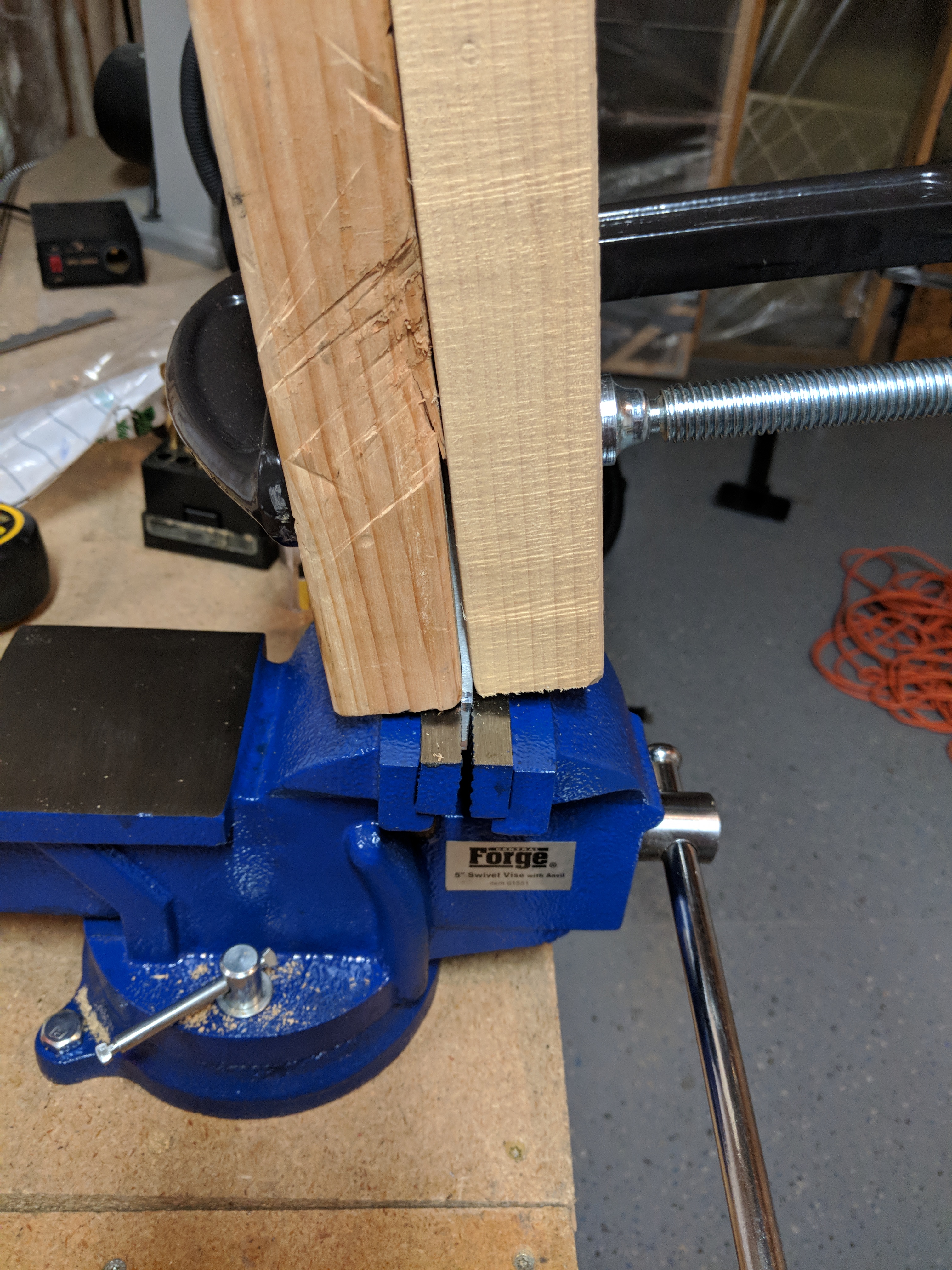
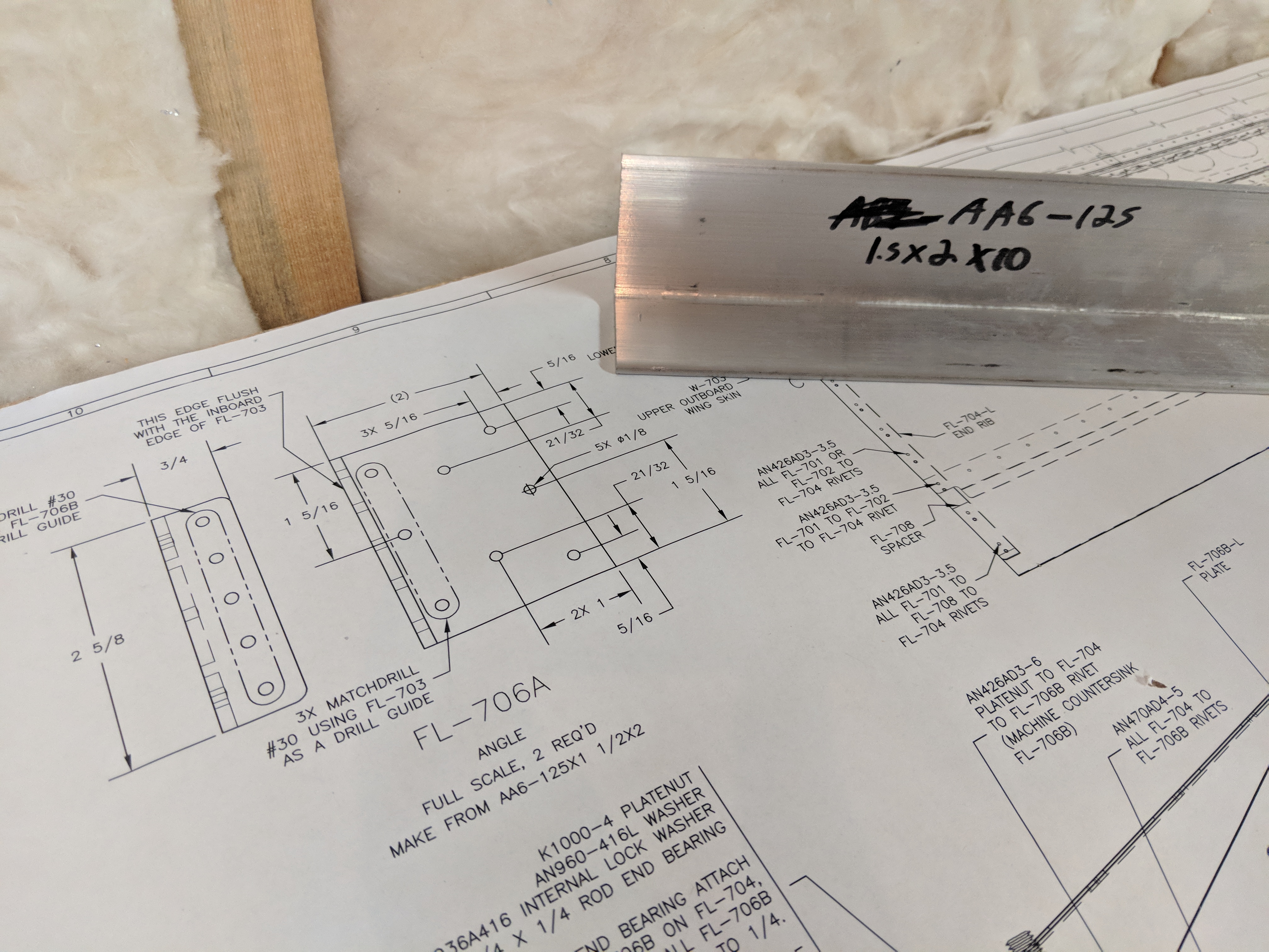
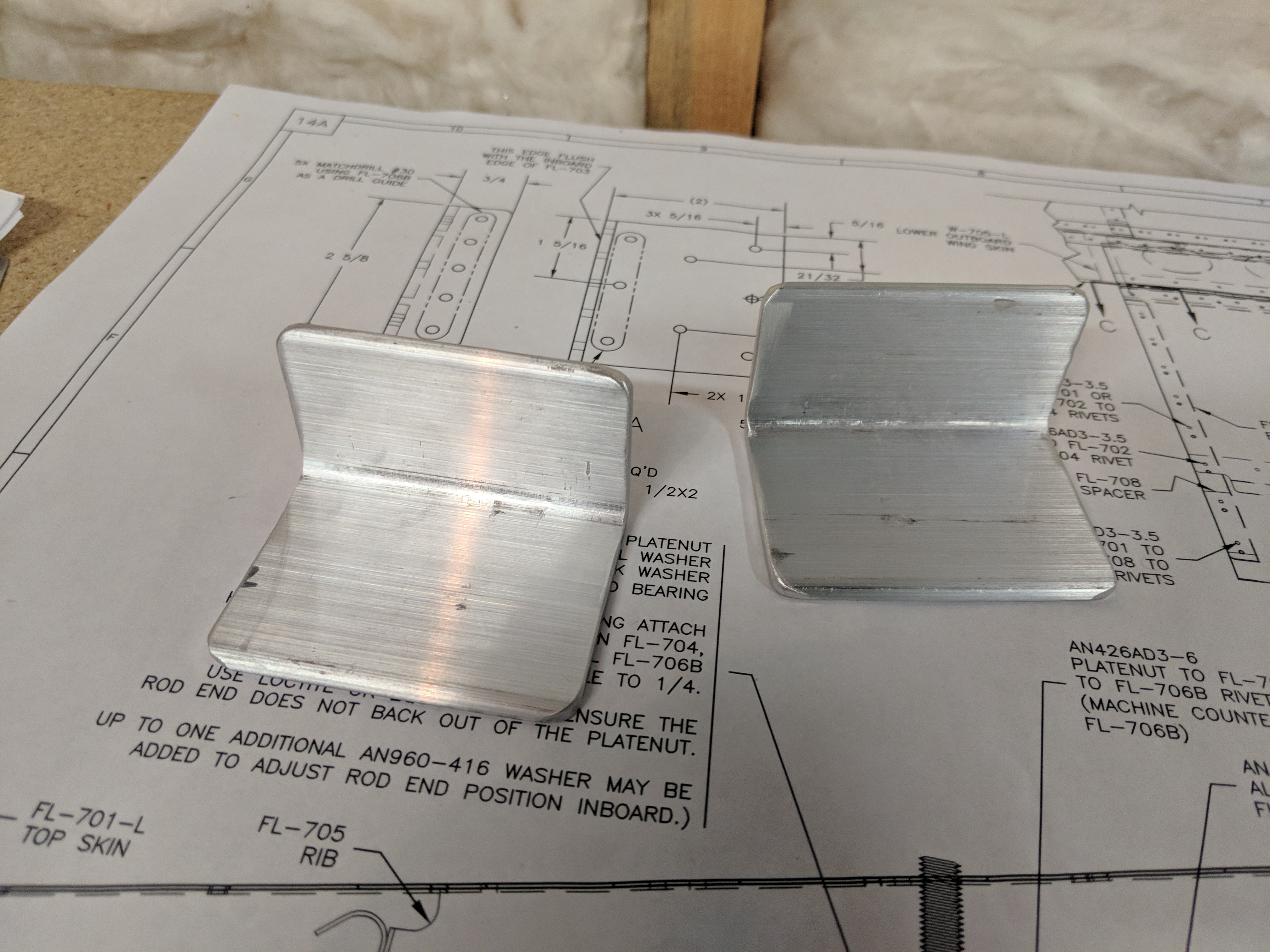
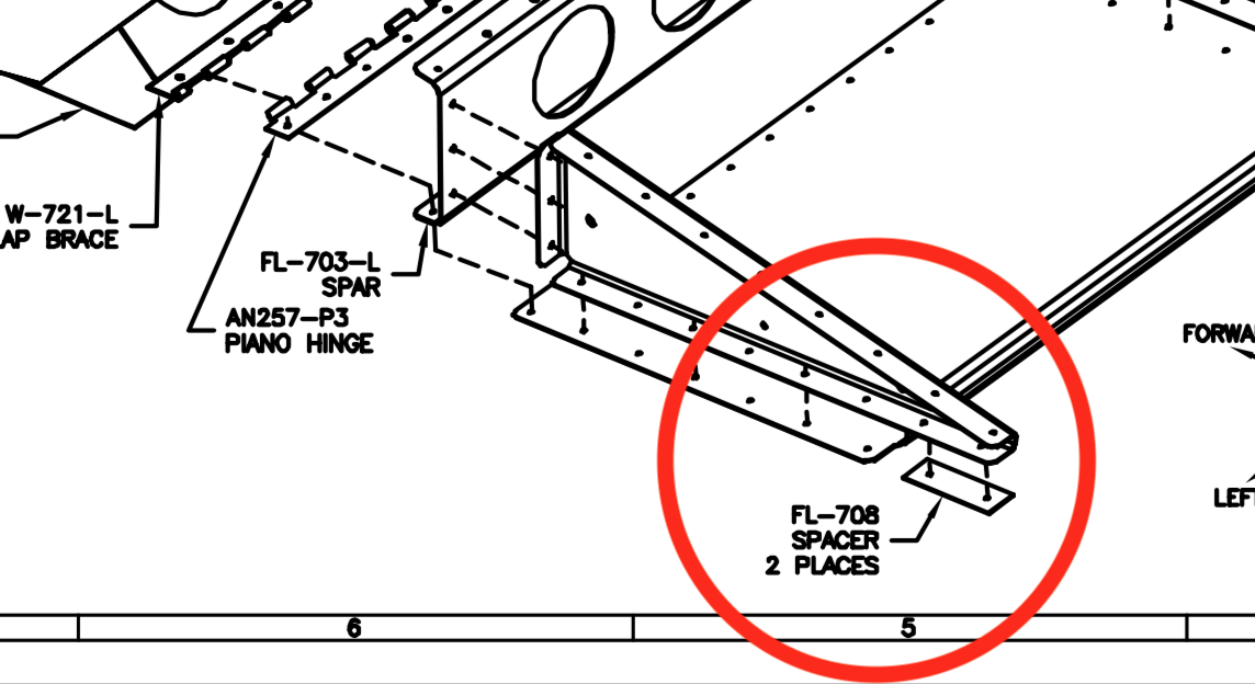
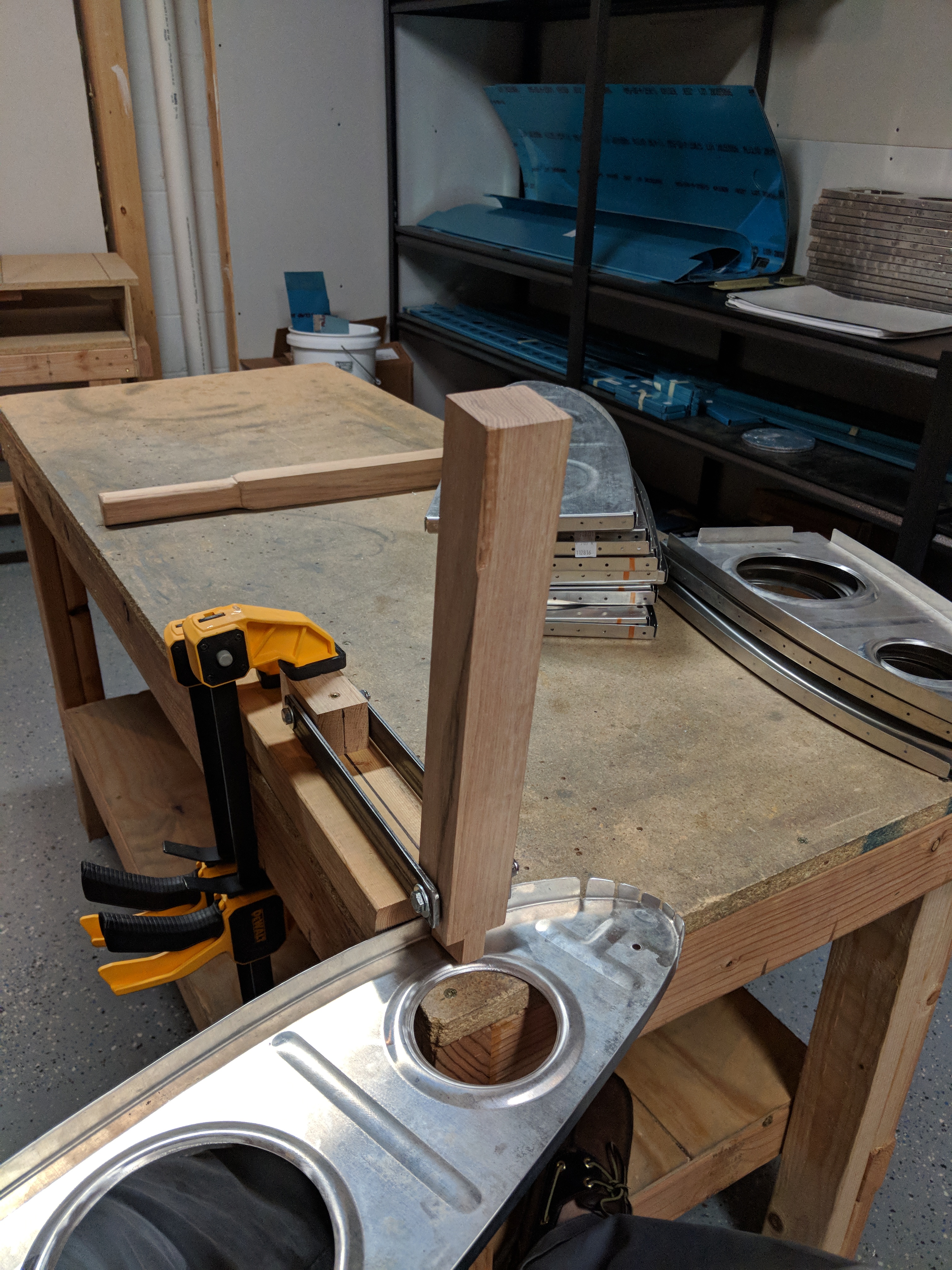
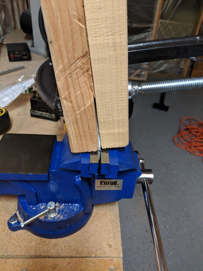
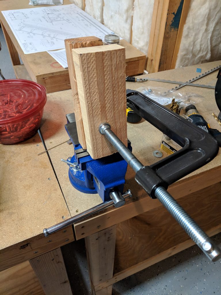
I found a Harbor Freight 25% off coupon, so what better time to buy a bench vise 🙂 I wound up with a semi-cheap 5″ vise that should do all I need it to.  I drilled some mounting holes in my work bench and bolted it down and got right to work on bending the FL-706 doubler bracket.  I chucked it up in the vise, and then clamped some scrap 2×4 boards around the piece to make sure I got the bend to occur where I wanted it.  It worked out pretty good, I had to make a few trips back and forth to the flap rib to test fit, and bend a little more to get it perfect.

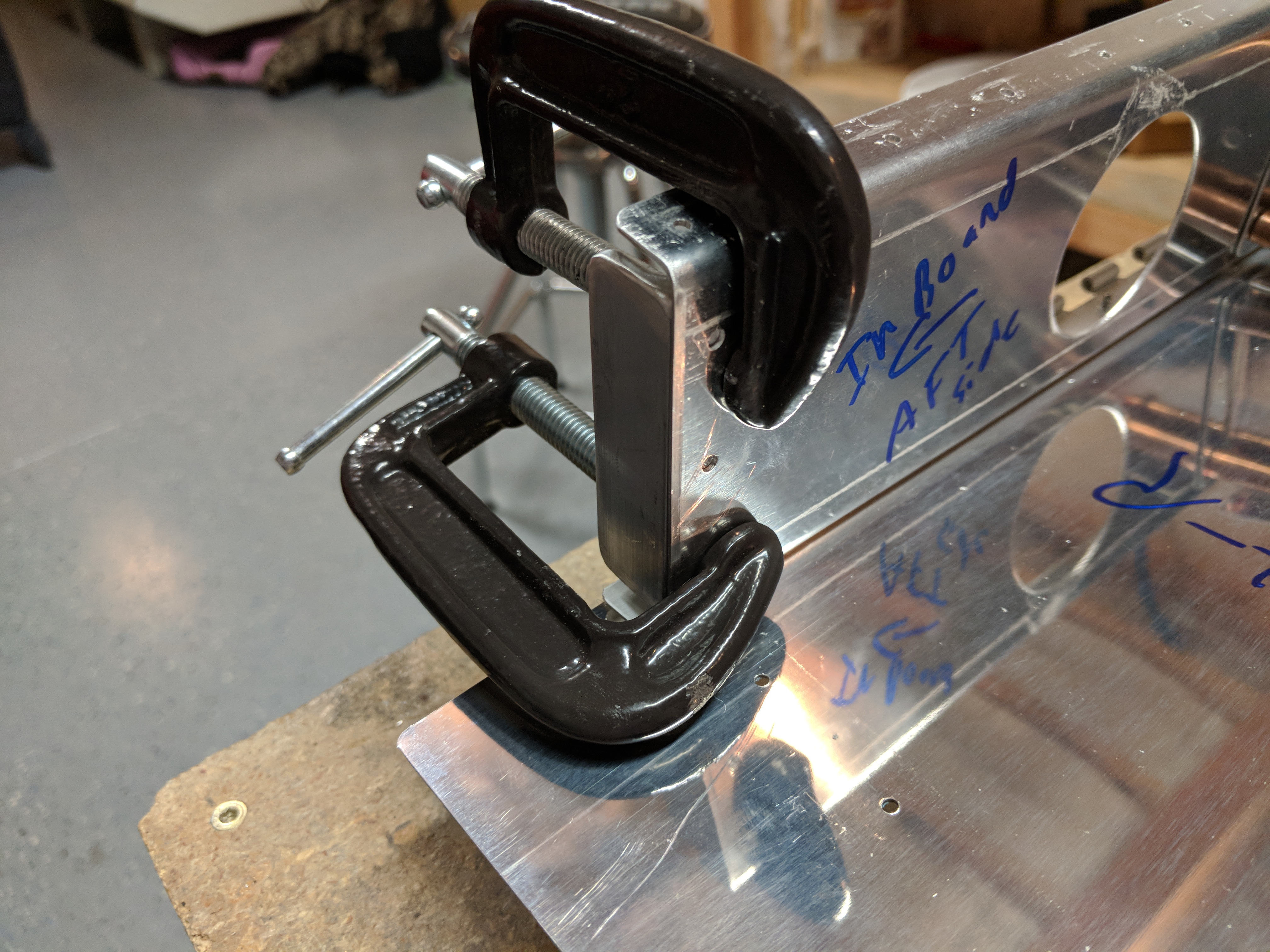
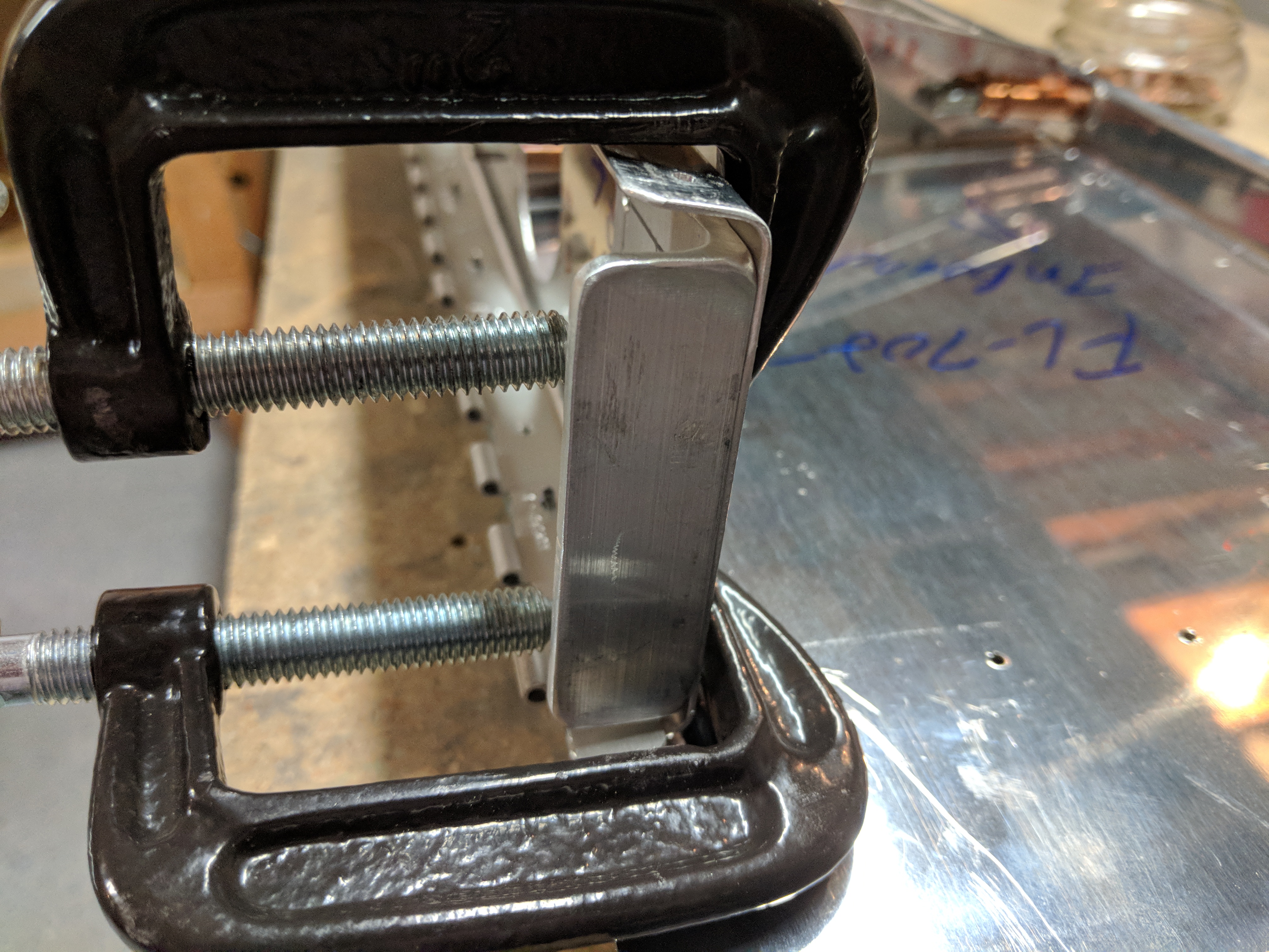
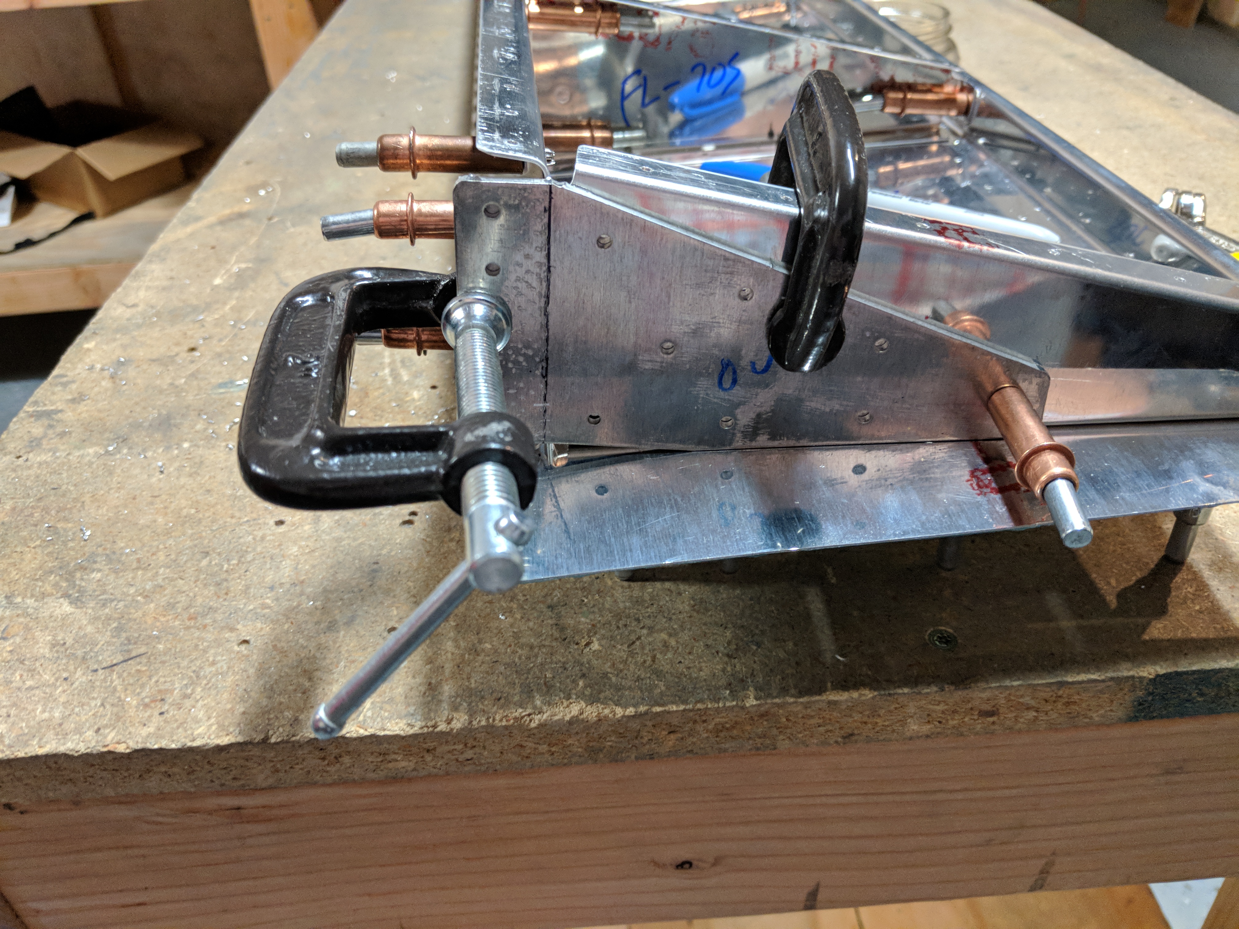
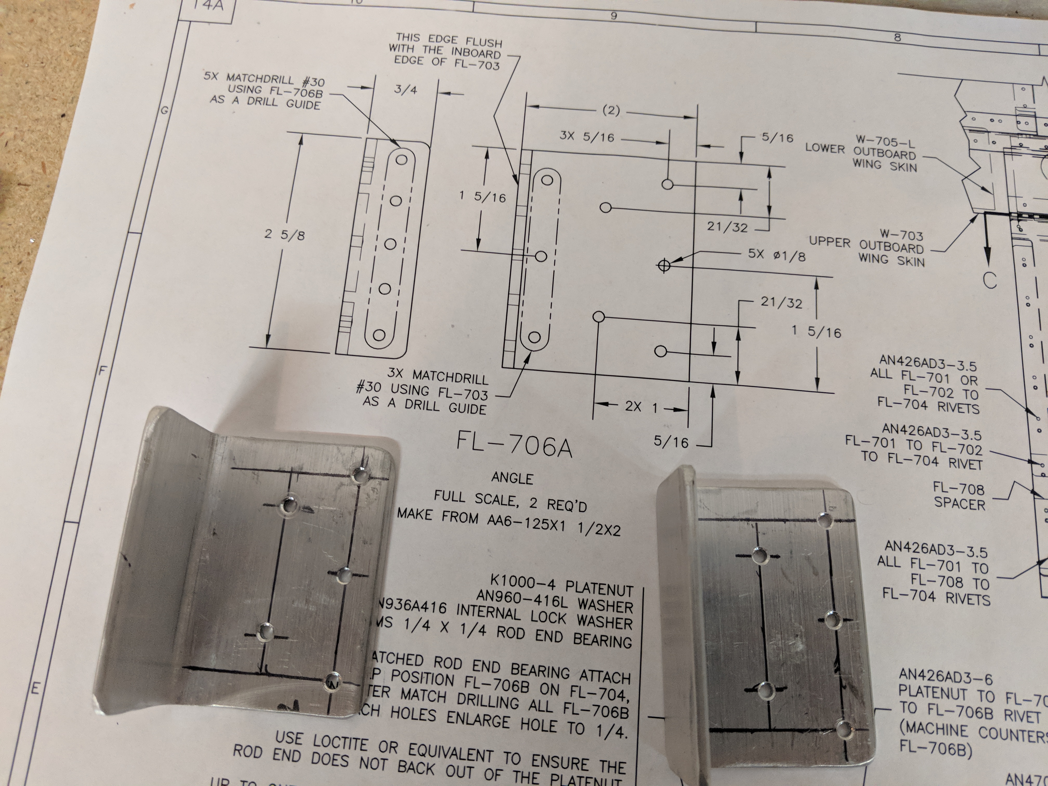
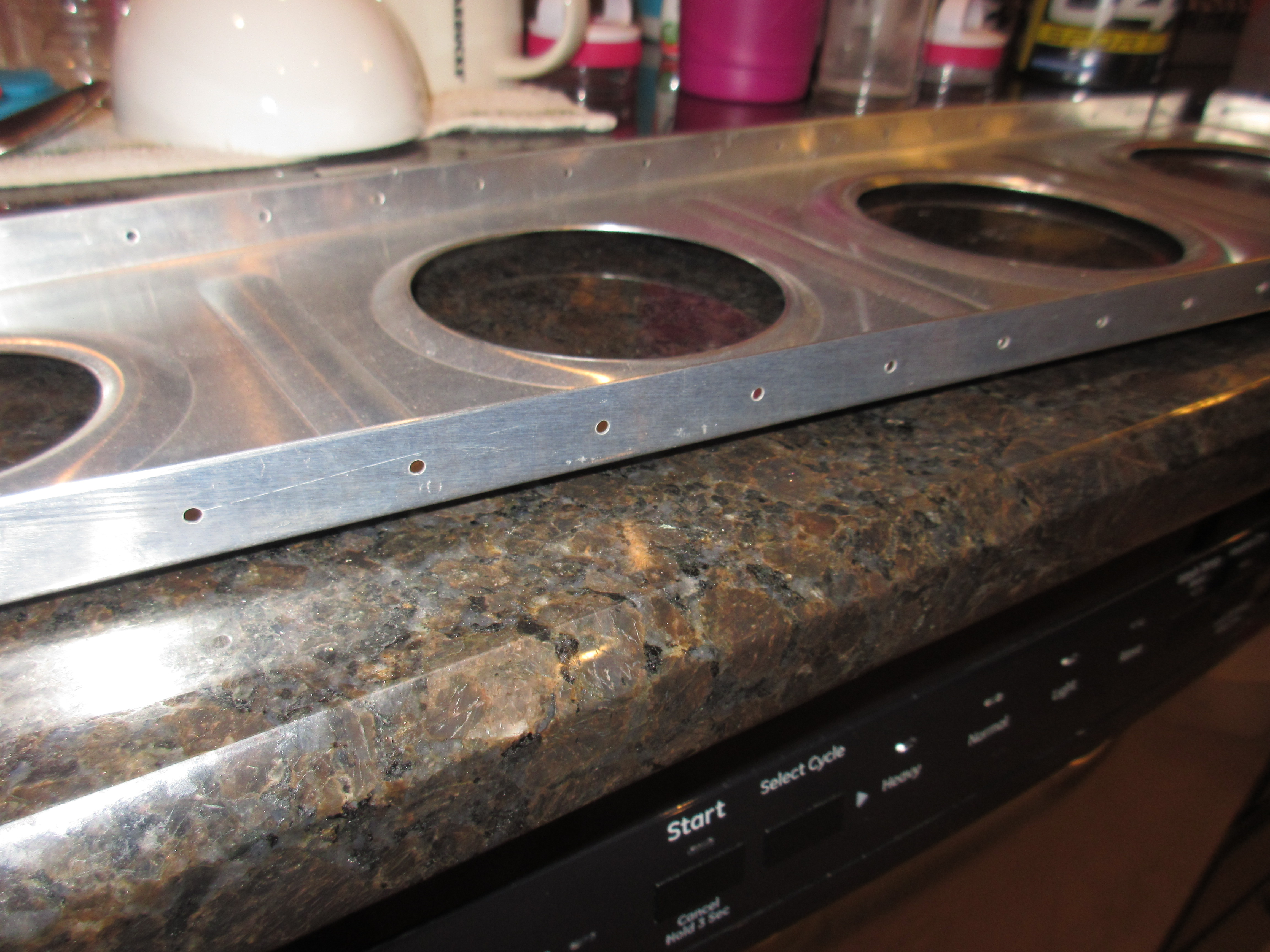
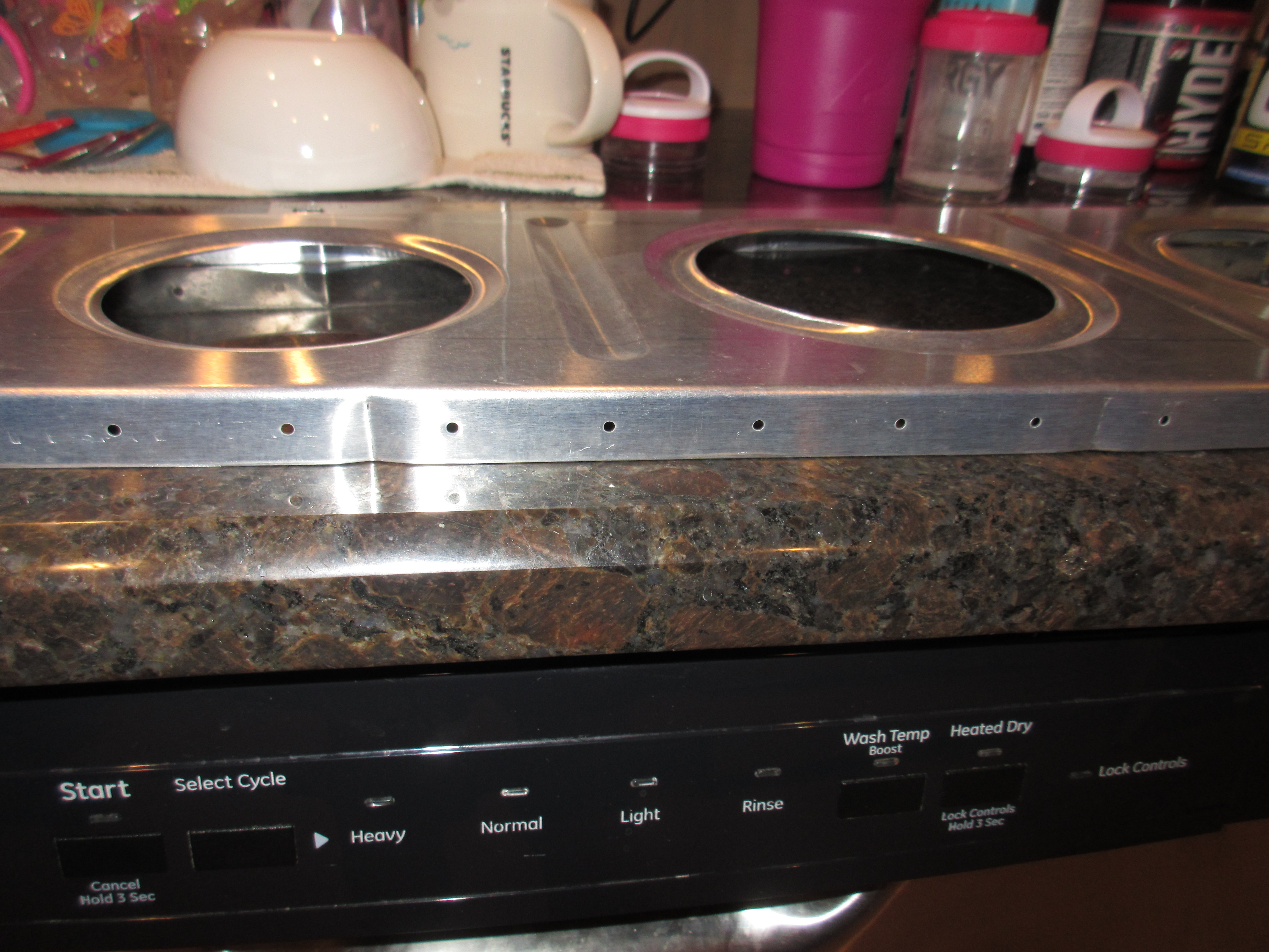
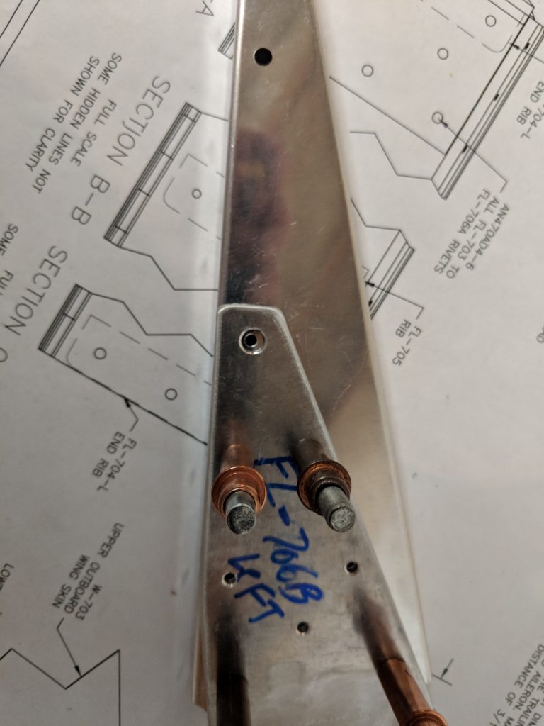
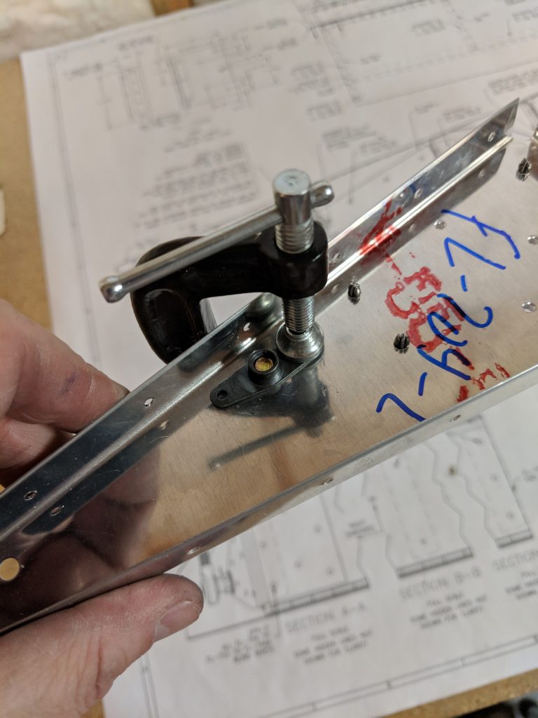
Once I had that 6.3 degree bend made, and had it lining up nice and flush against all the end rib, spar and spar doubler, I match drilled the doubler.  This was a bit tricky, as there is only one hole that is pre-punched in the rib and FL-706A doubler.  I used it for initial alignment, and then squared it up with the FL706-B doubler and then used some C-clamps to hold everything tight while I back drilled.

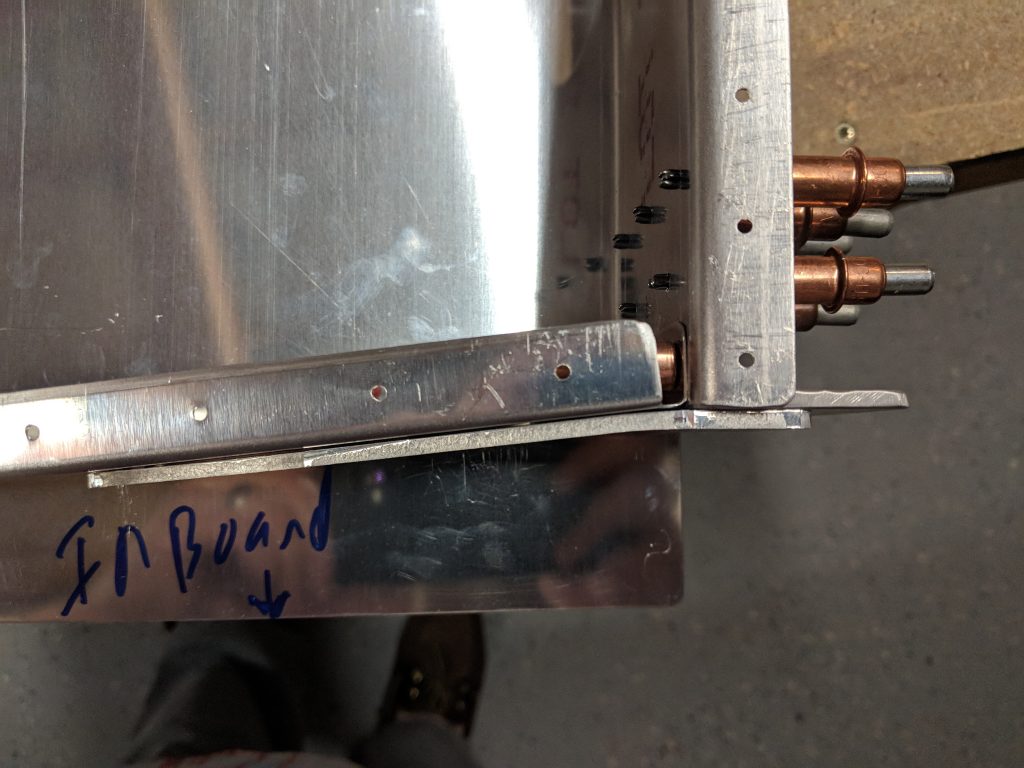
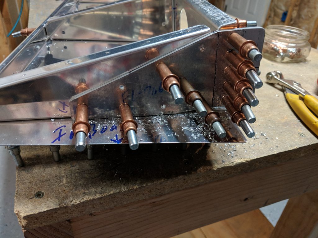
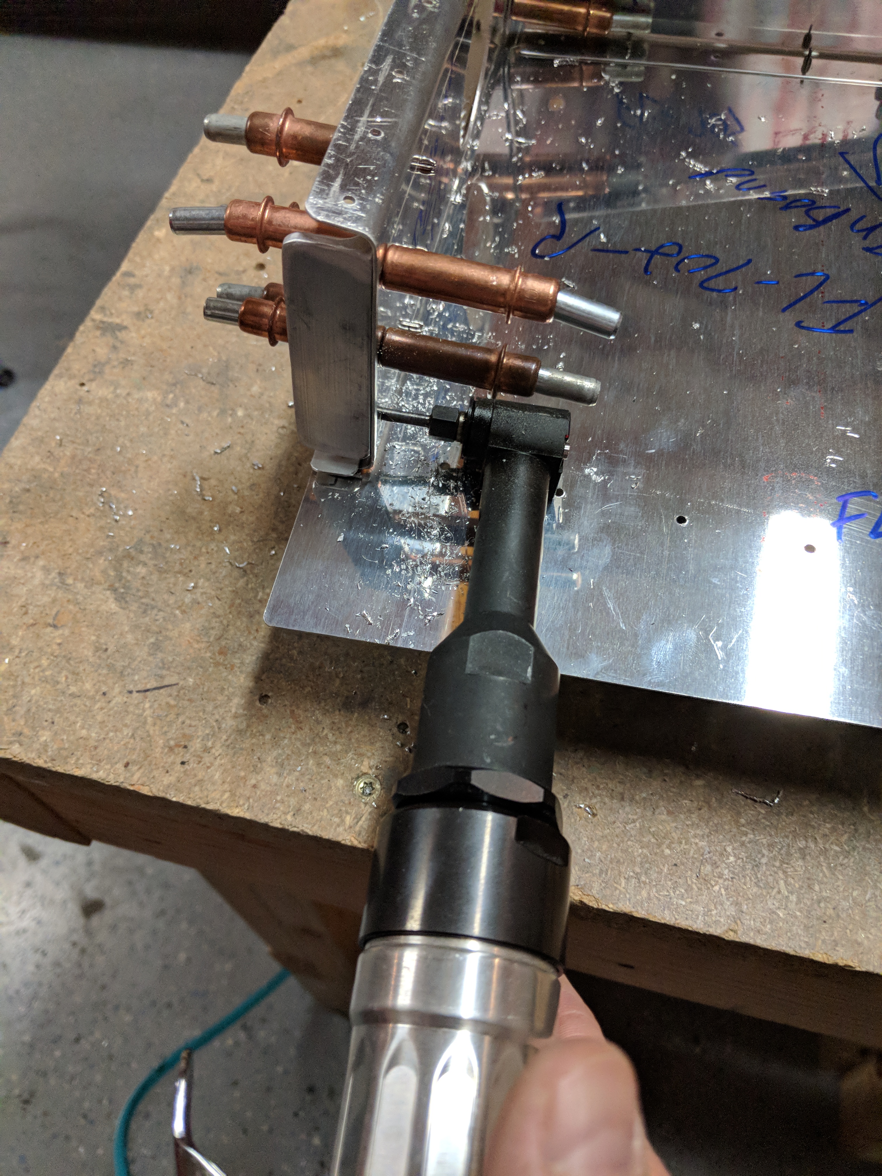
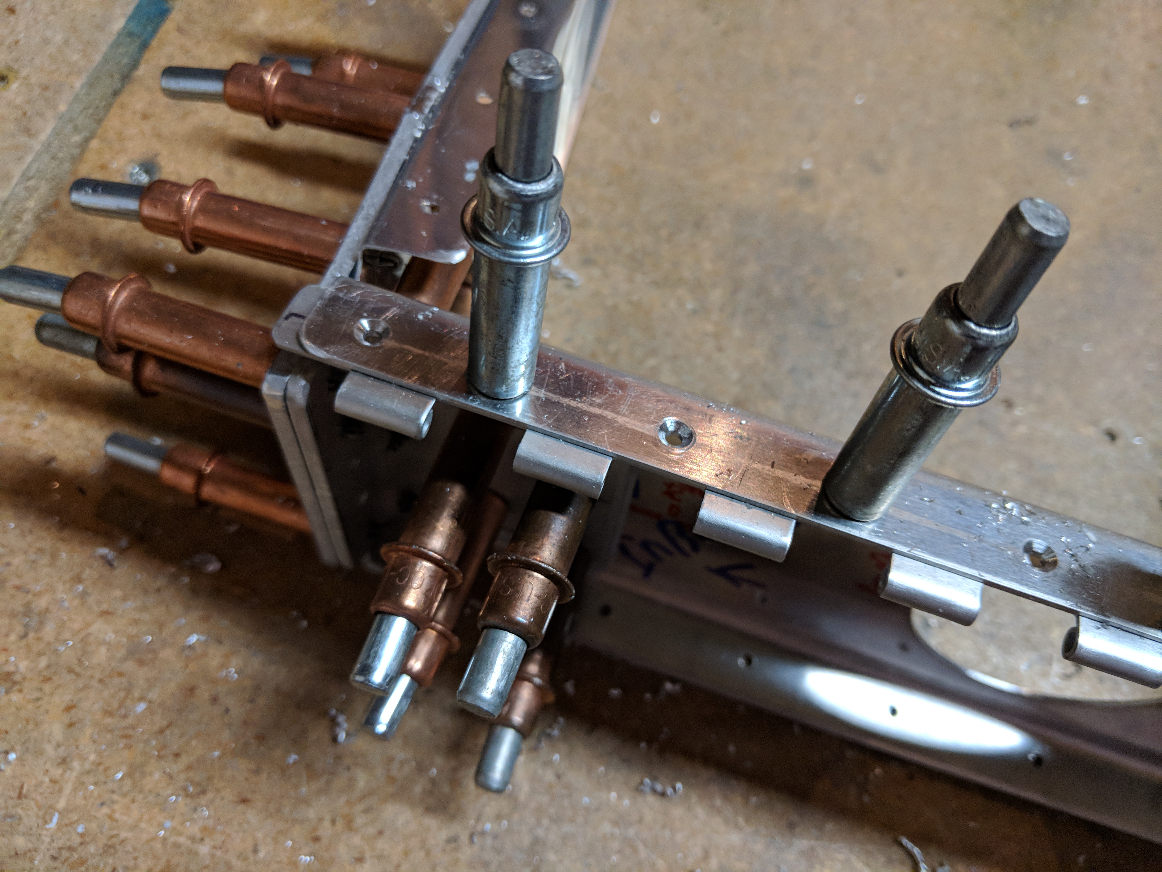
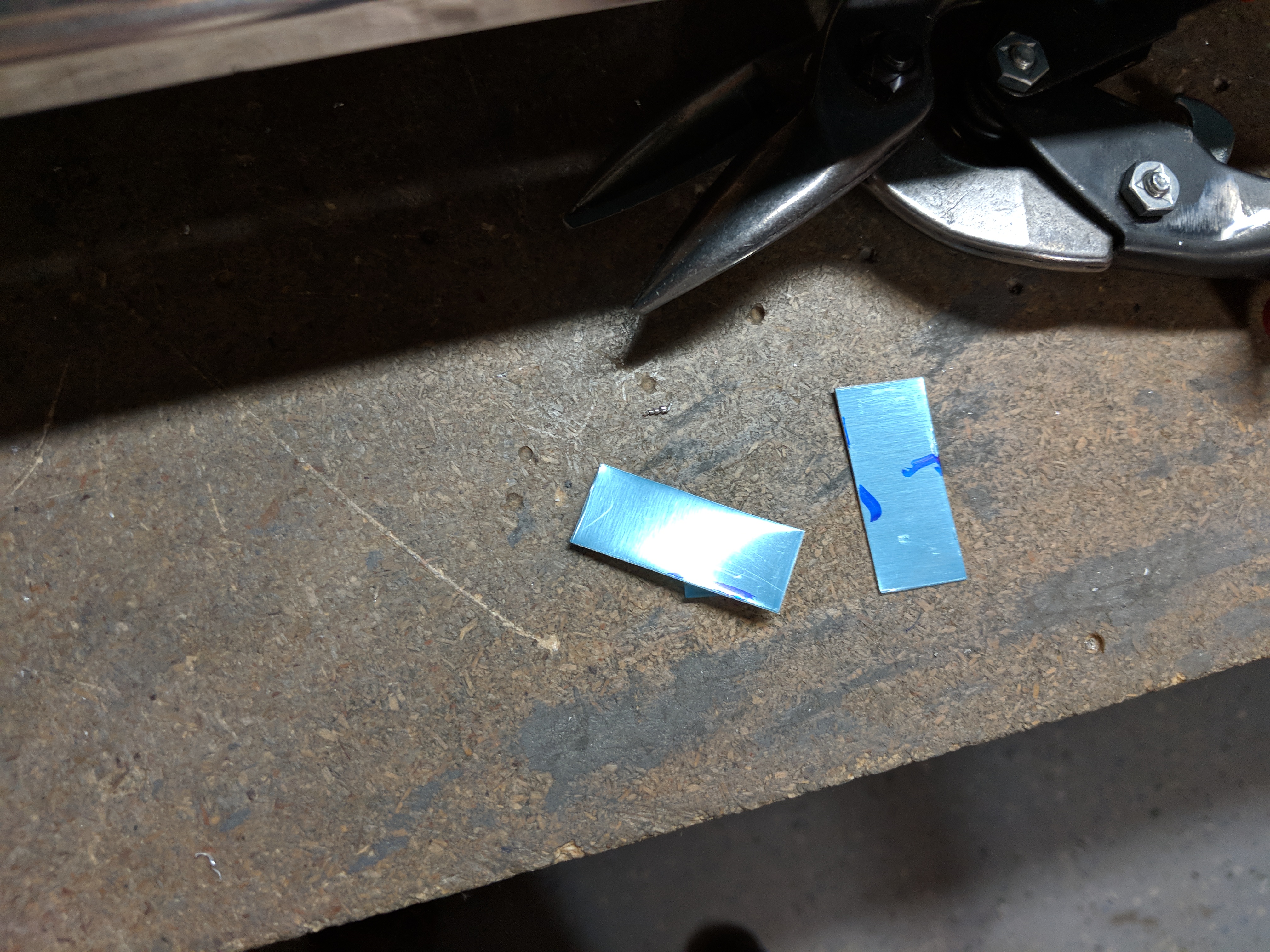
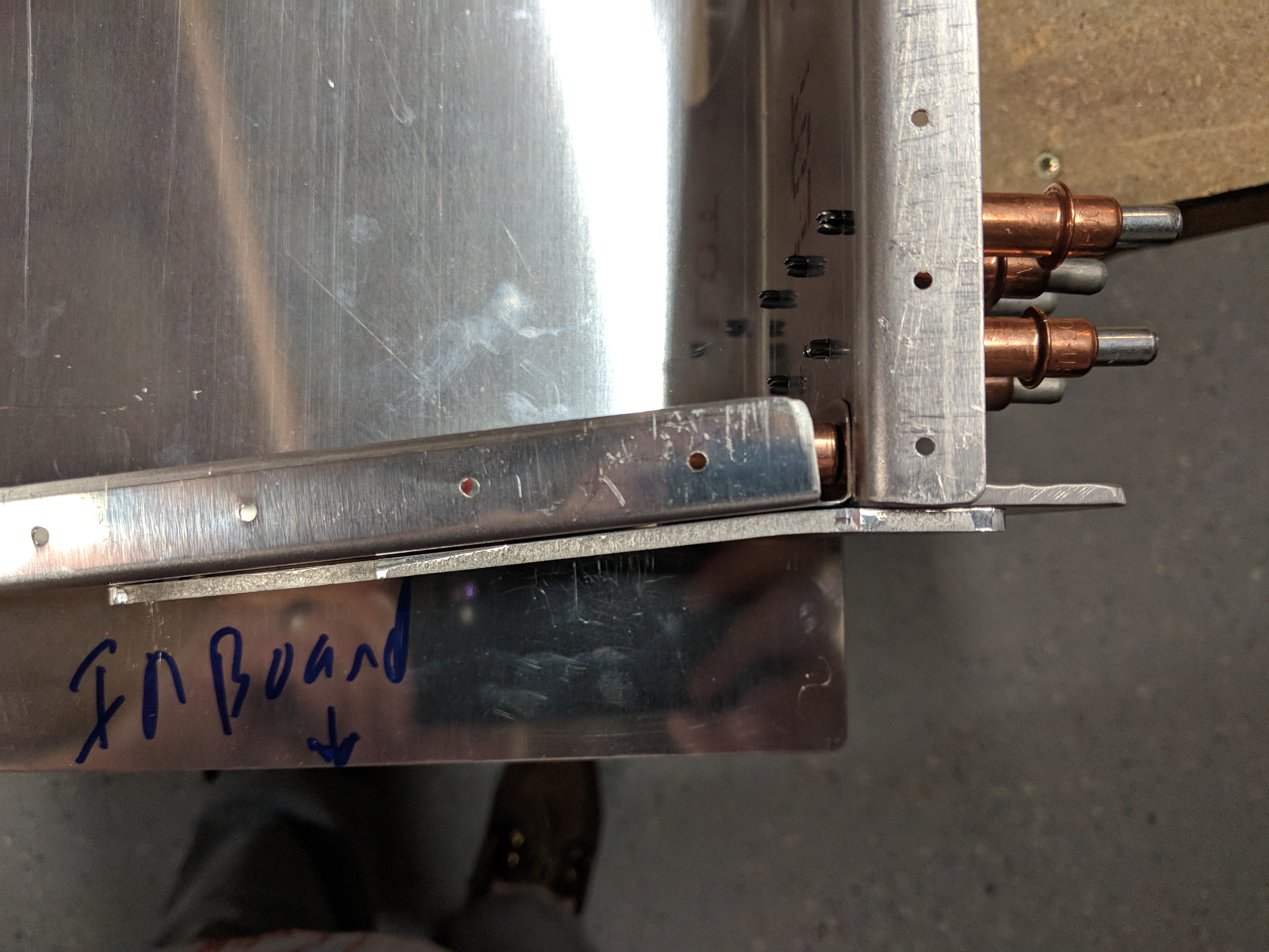
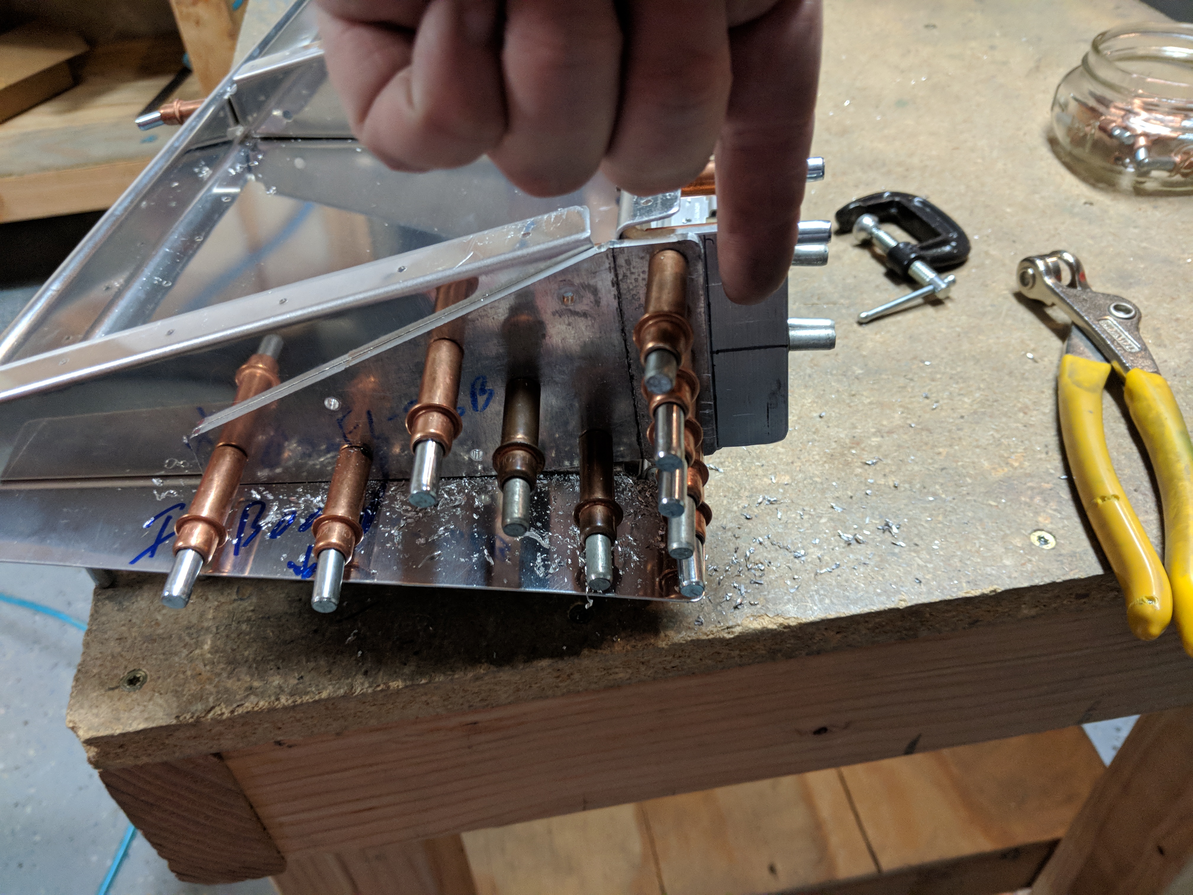
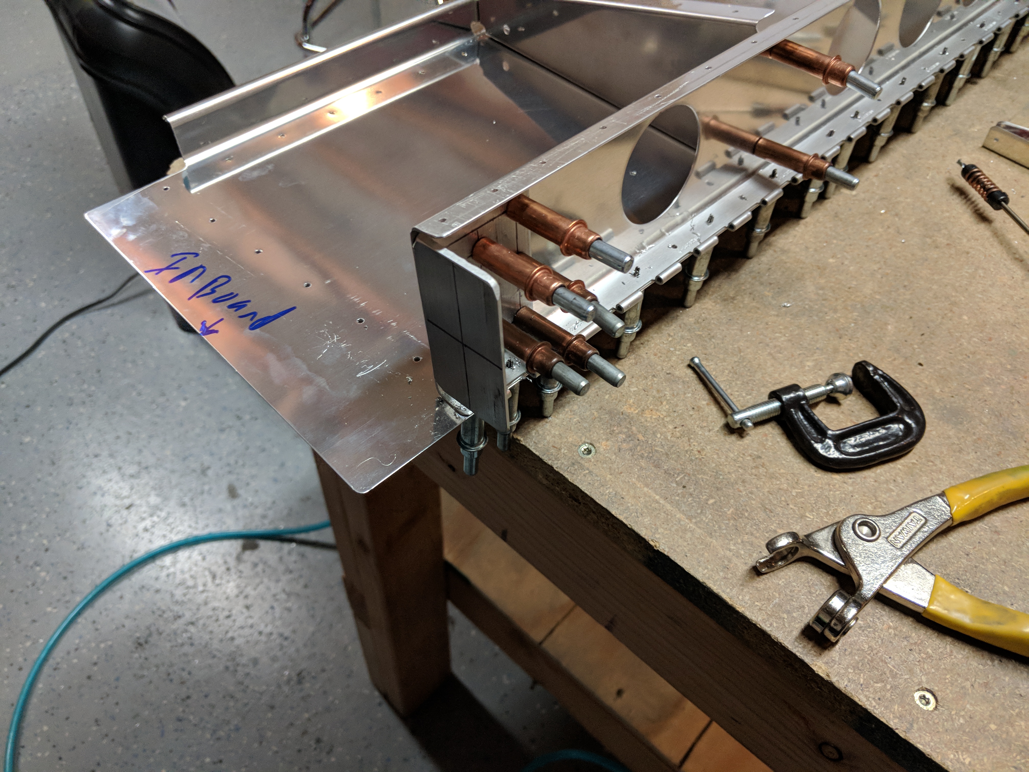
I didn’t get any photos of my C-clamps, but they were just clamped onto the forward end of the FL-706A doubler and the FL-706B doubler.  Then I drilled the holes into FL-706B using the holes in FL-706A as my guides, clecloing them as I went.  Once that was done, I back drilled the holes in the FL-704 end rib using FL-706A as a guide, again clecoing as I went to hold things still.  One that was done, I decided it was tie to cut off the excess material from FL-706B spar doubler, as I had left it on purpose to help with clamping and aligning.  I am glad I did that, since it worked out pretty nicely. My finger below is pointing to this excess that needs trimmed.

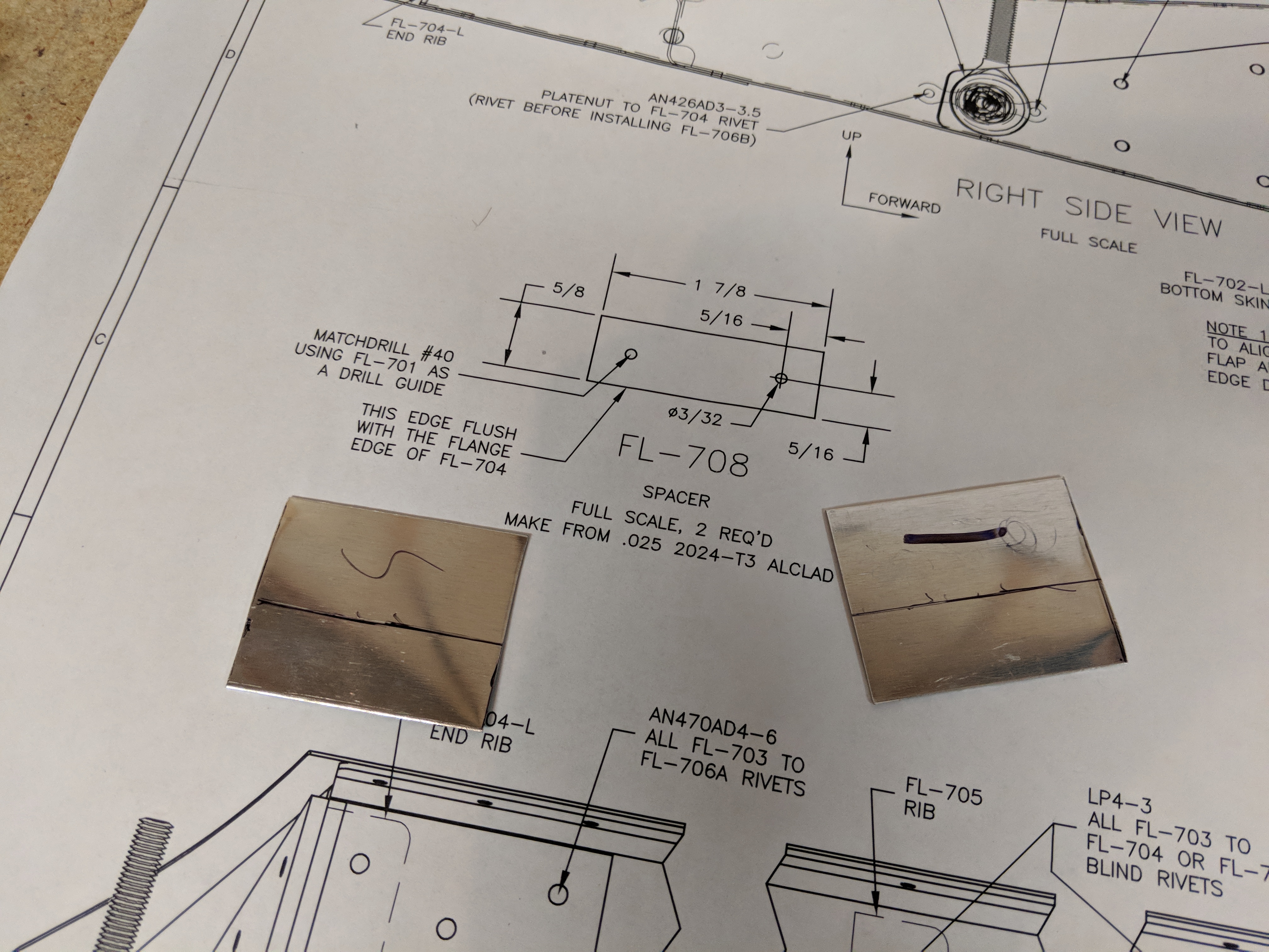
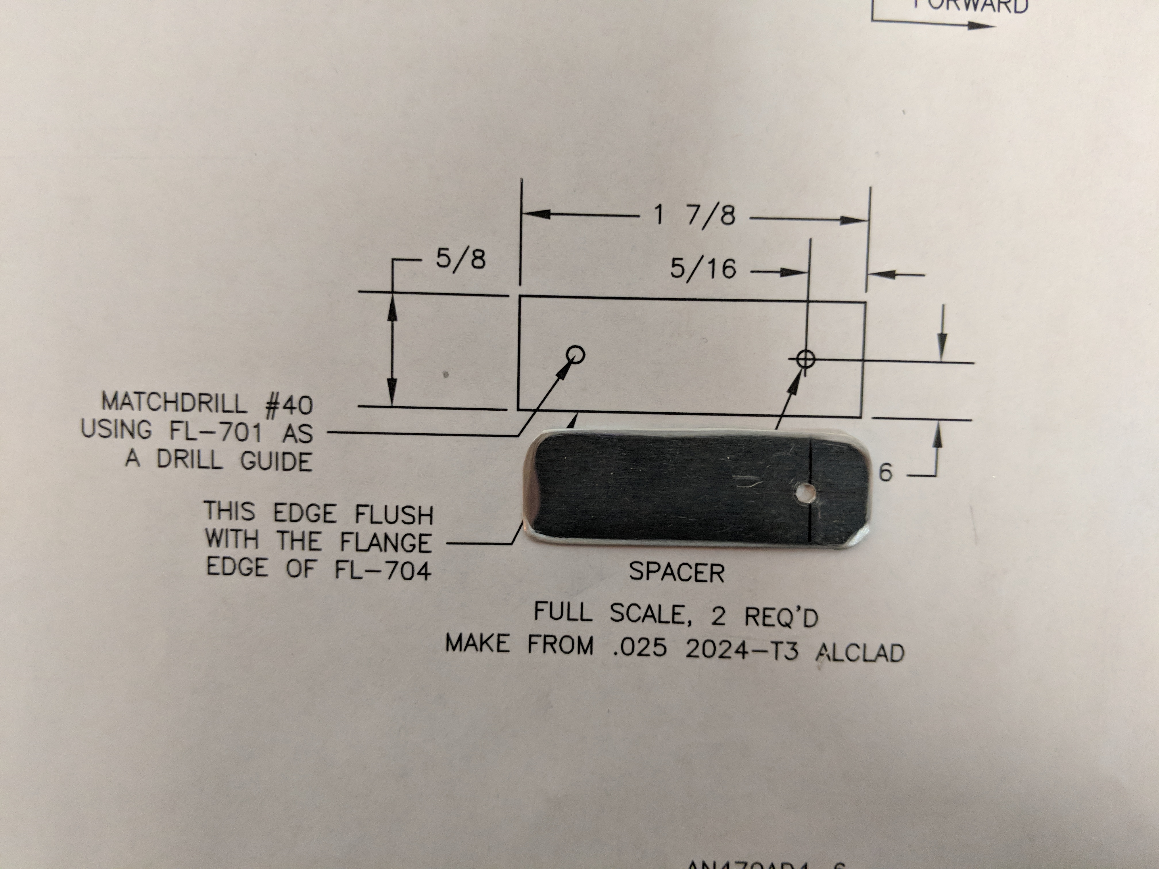
I trimmed it using my bandsaw and then removed both doublers as well as the FL-704 end rib to finish up the last little bits of work on them.  I need to open up the very end hole on FL-706A (in the trailing edge most end) to make room for the 1/4 bolt that connects the flap to the flap motor/pushrod.  It’s attached using a K1000-4 nutplate that goes on the inside of the flap.  The first step was to enlarge the #30 hole into a 1/4″ hole in both the FL-706A doubler and the FL-704 end rib.  I wanted to make sure this hole was drilled true so I chucked up my 1/4″ bit in the drill press and used it to enlarge the hole on the thick doubler.  Then, I clecoed the doubler back onto the end rib and used that new larger hole to match drill the end rib hole.

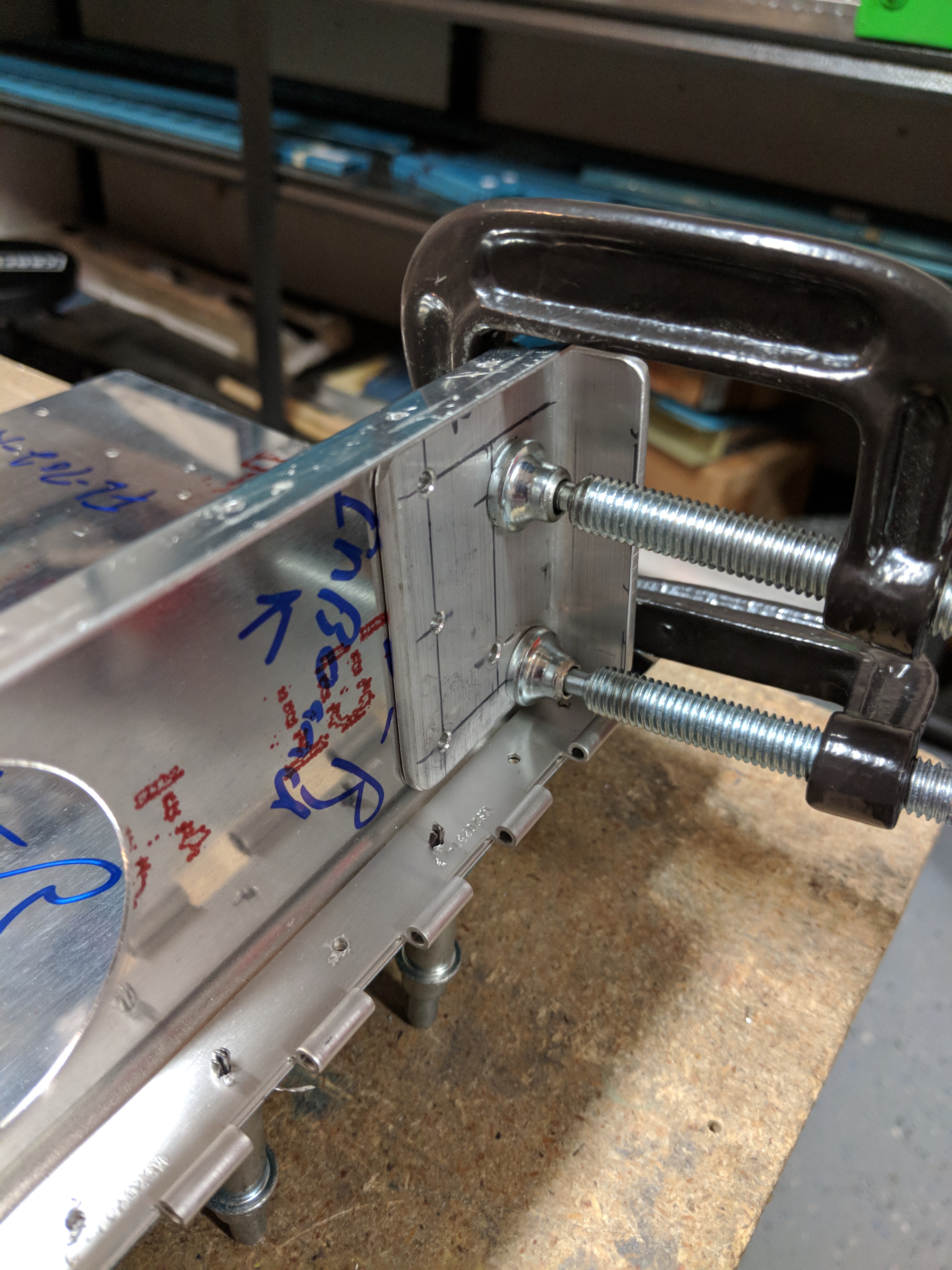
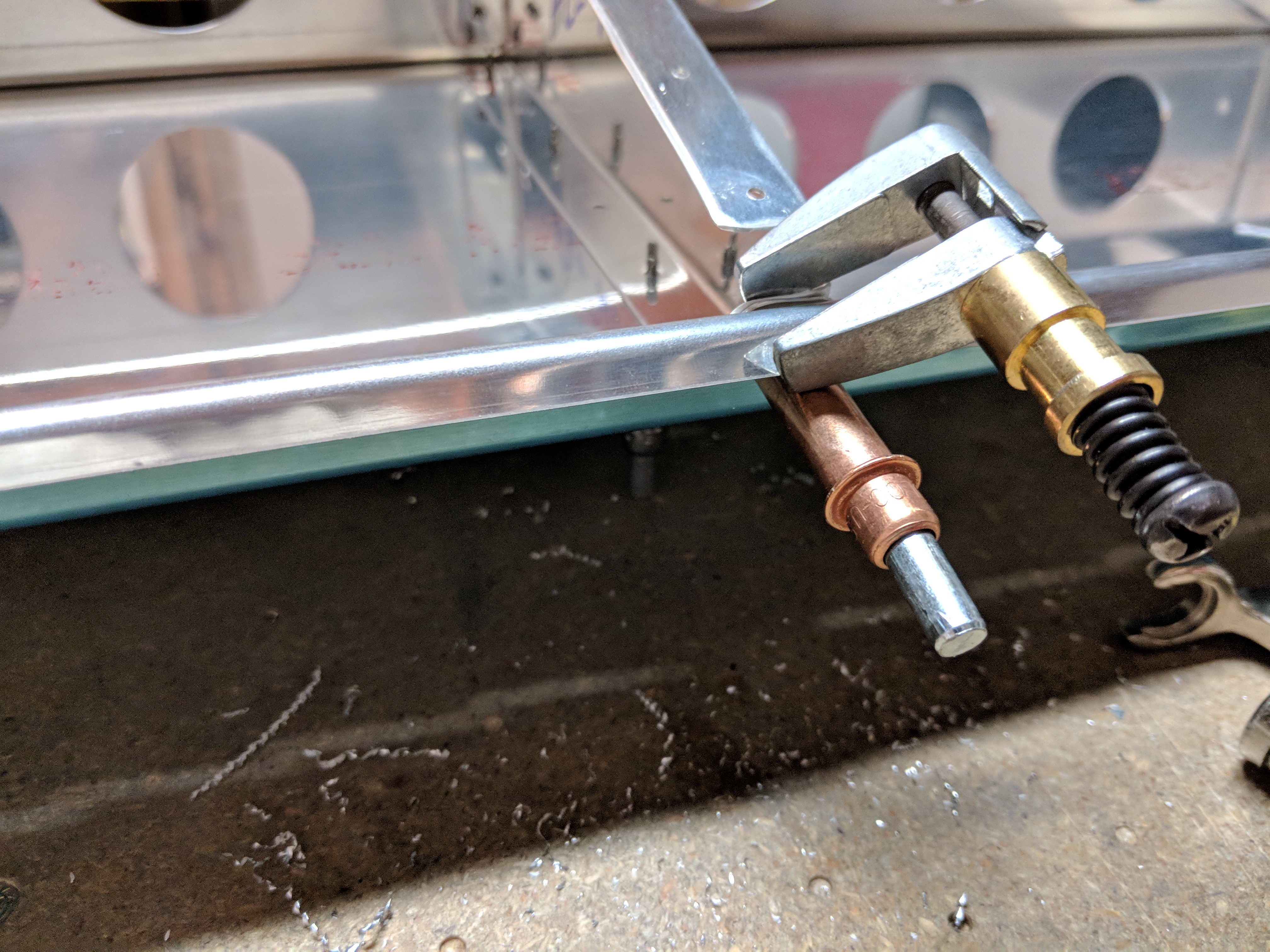
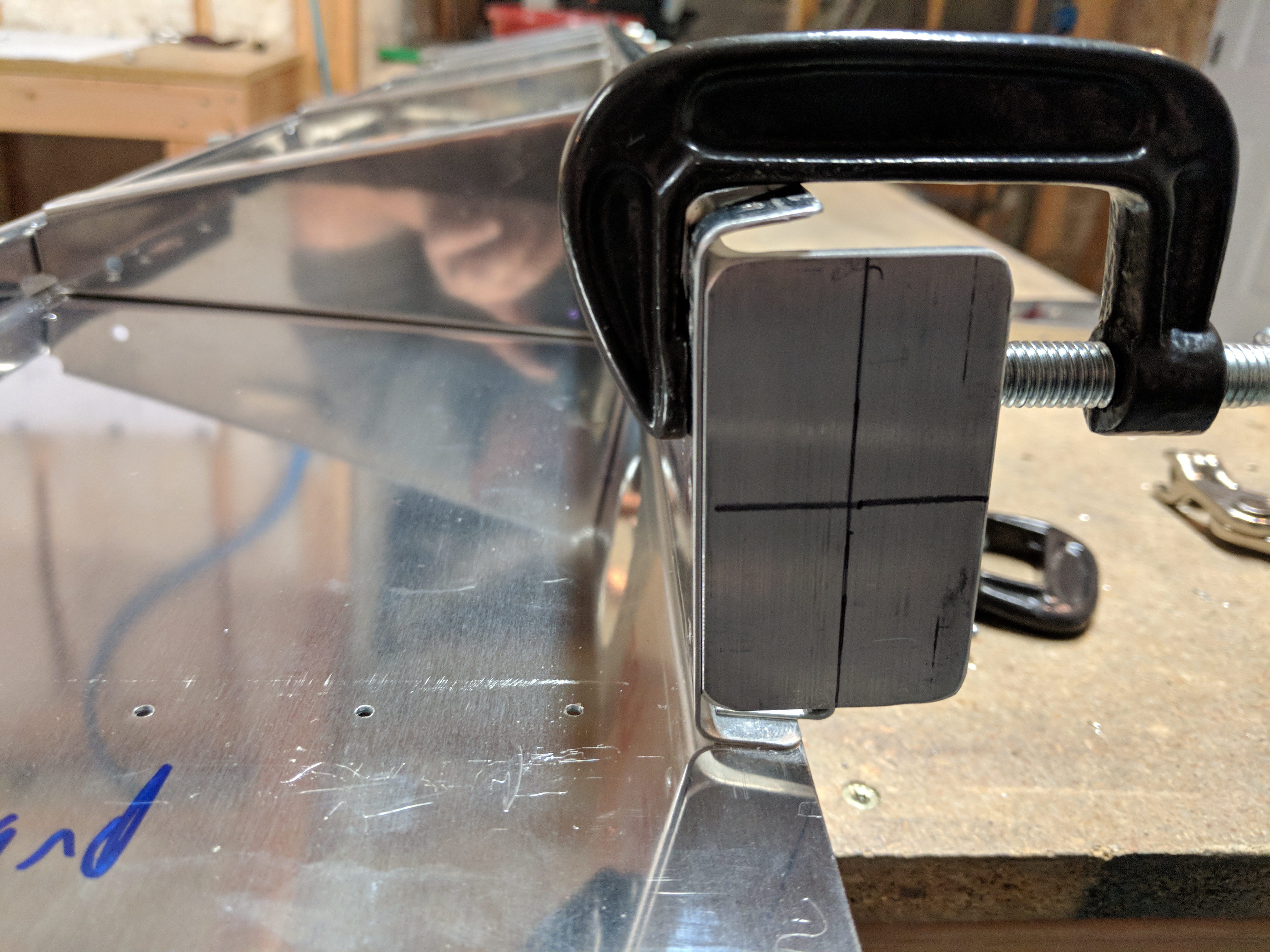
To make sure I got this lined up correctly, I picked out an AN4 bolt from the supplies and a K1000-4 nutplate.  I threaded the bolt through the doublers/rib and put the nutplate on the back.  Then I use a C-clamp to hold one leg of the nutplate so I could drill the other leg.

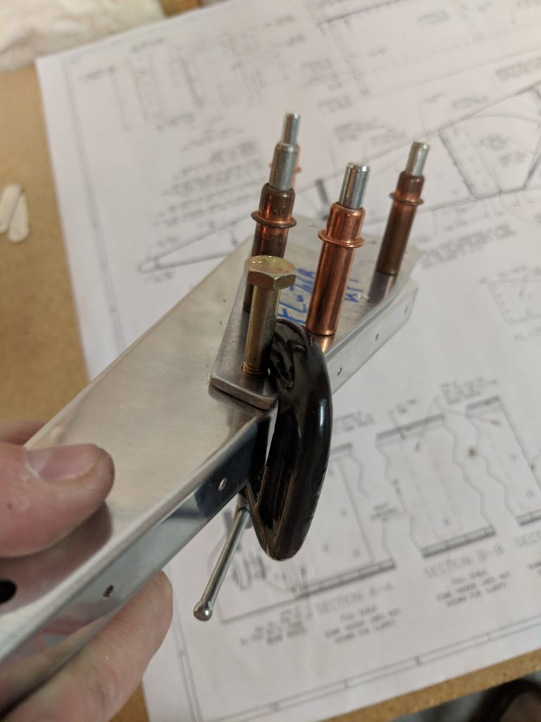
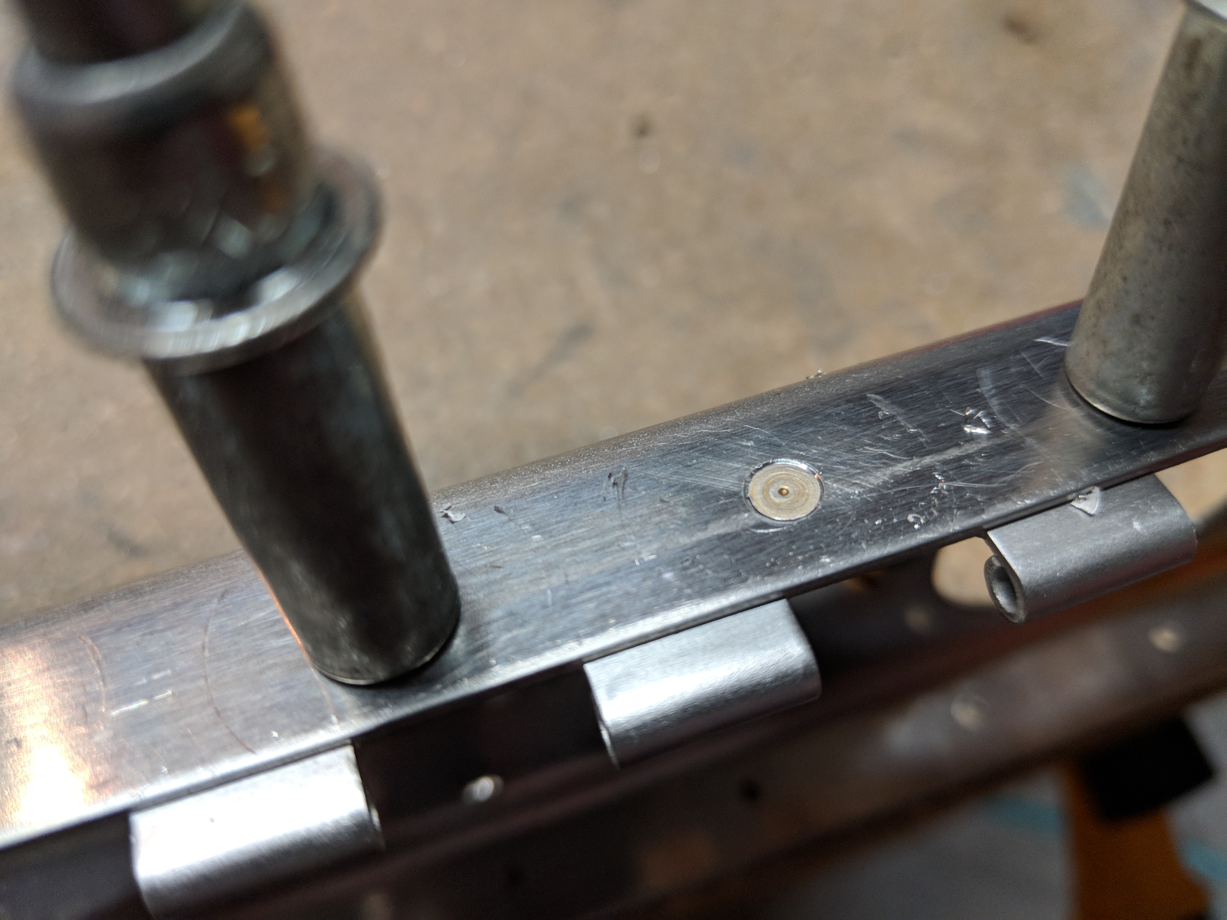
Then I back drilled the rib and doubler using the nutplate as the guide.  Once I had one hole drilled, I stuck a cleco in the new hole and removed the C-clamp an drilled the other hole in the nutplate.  Now that the holes for the nutplate were drilled, I had to countersink them.  We countersink one hold on the FL-704 end rib and then the other hole is actually in the Fl-706A doubler.  I used my countersink bit screwed into my deburring handle so I could gingerly countersink the thin metal on the rib.  I used a spar AN426AD3-7 rivet to check my depth, and then did the same on the doubler.

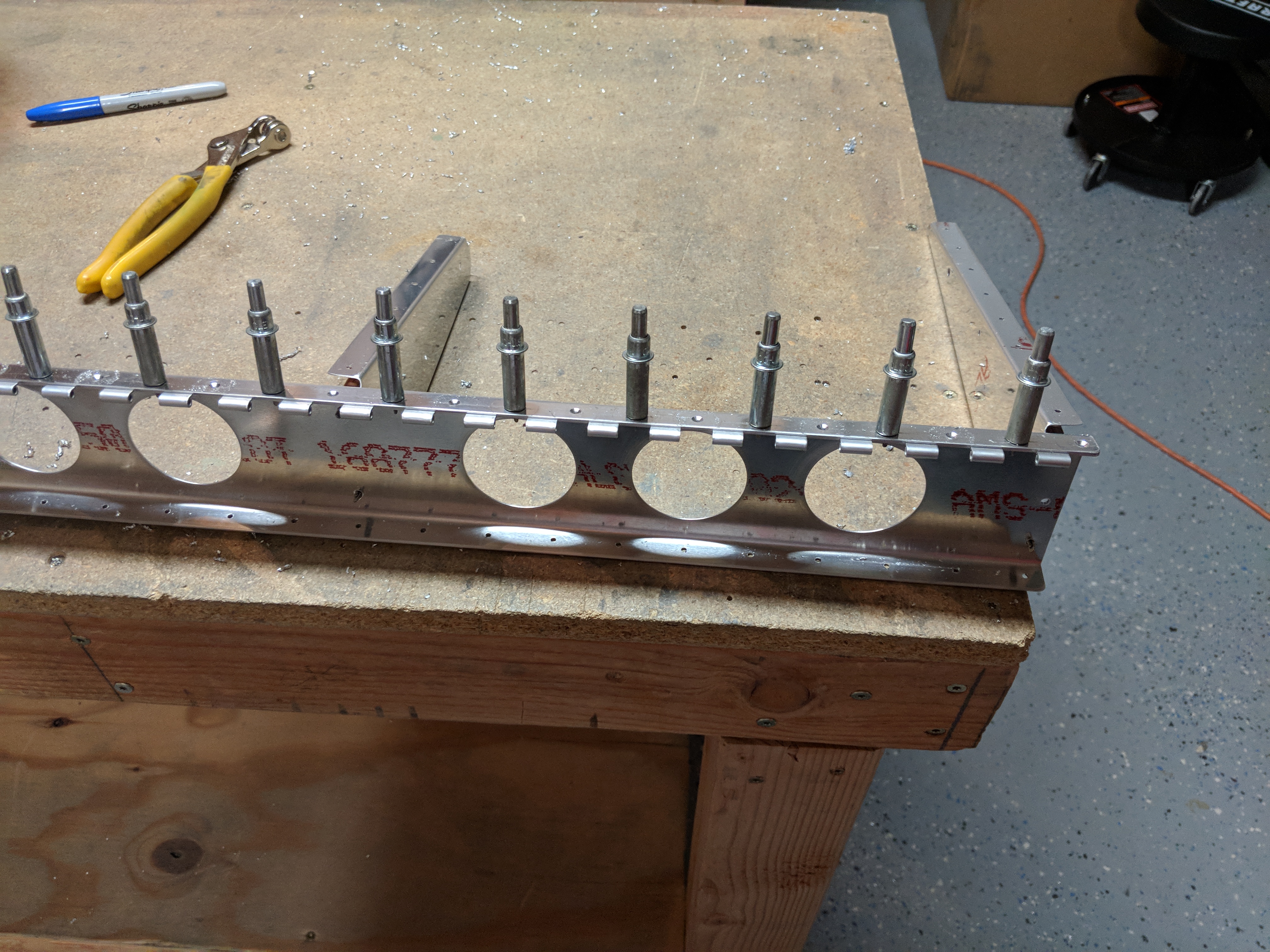
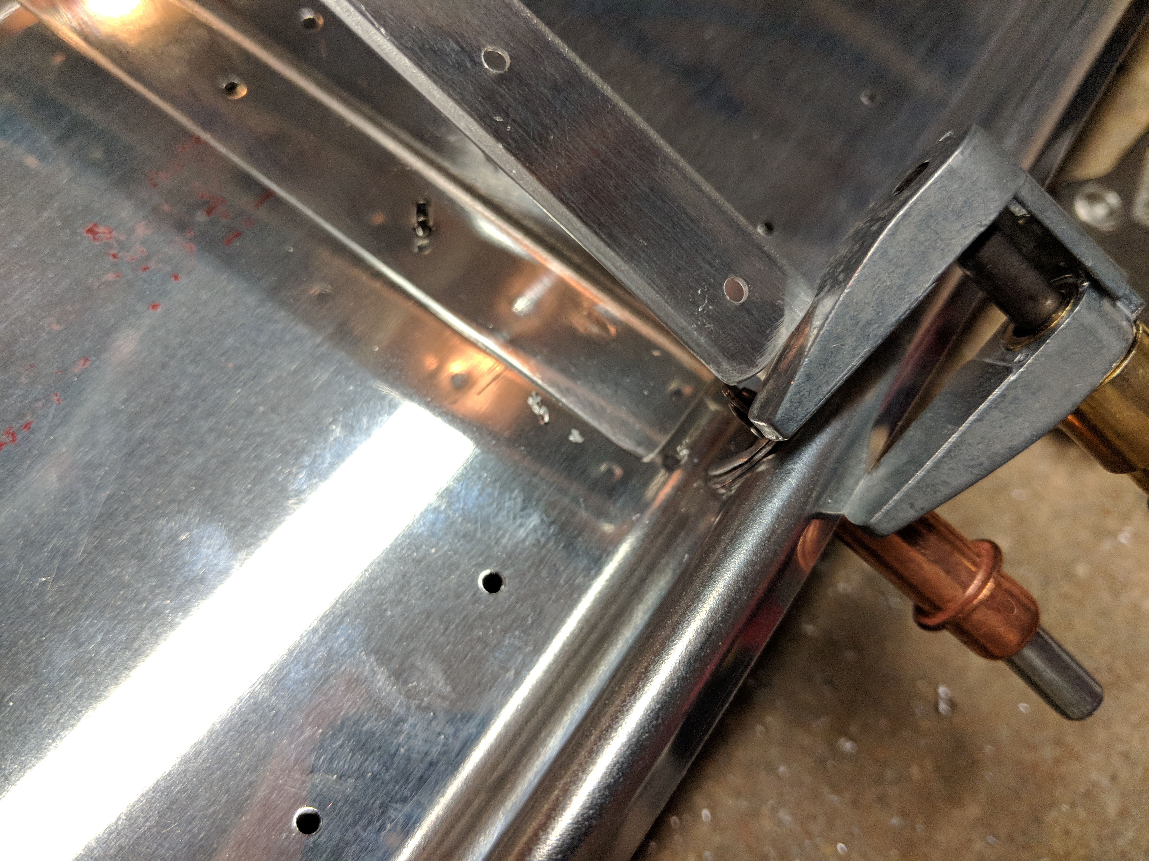
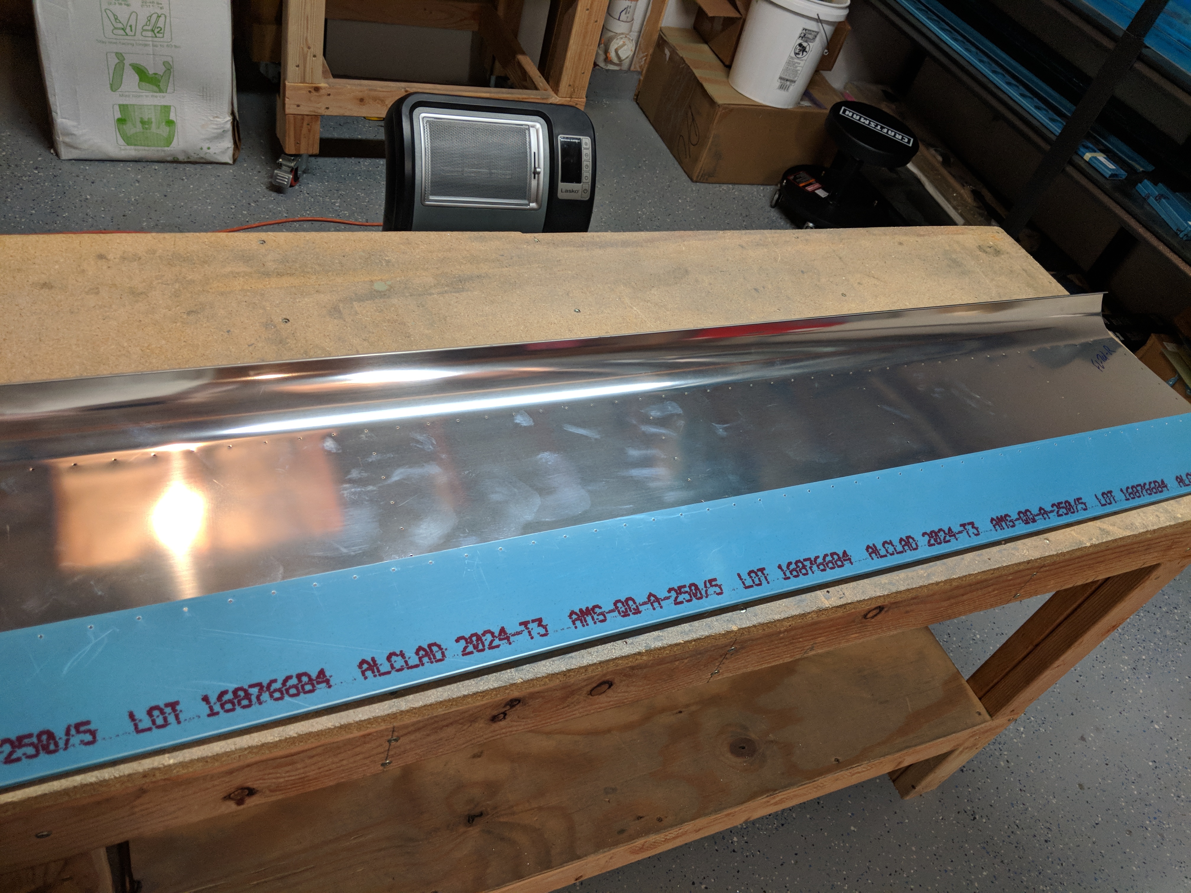
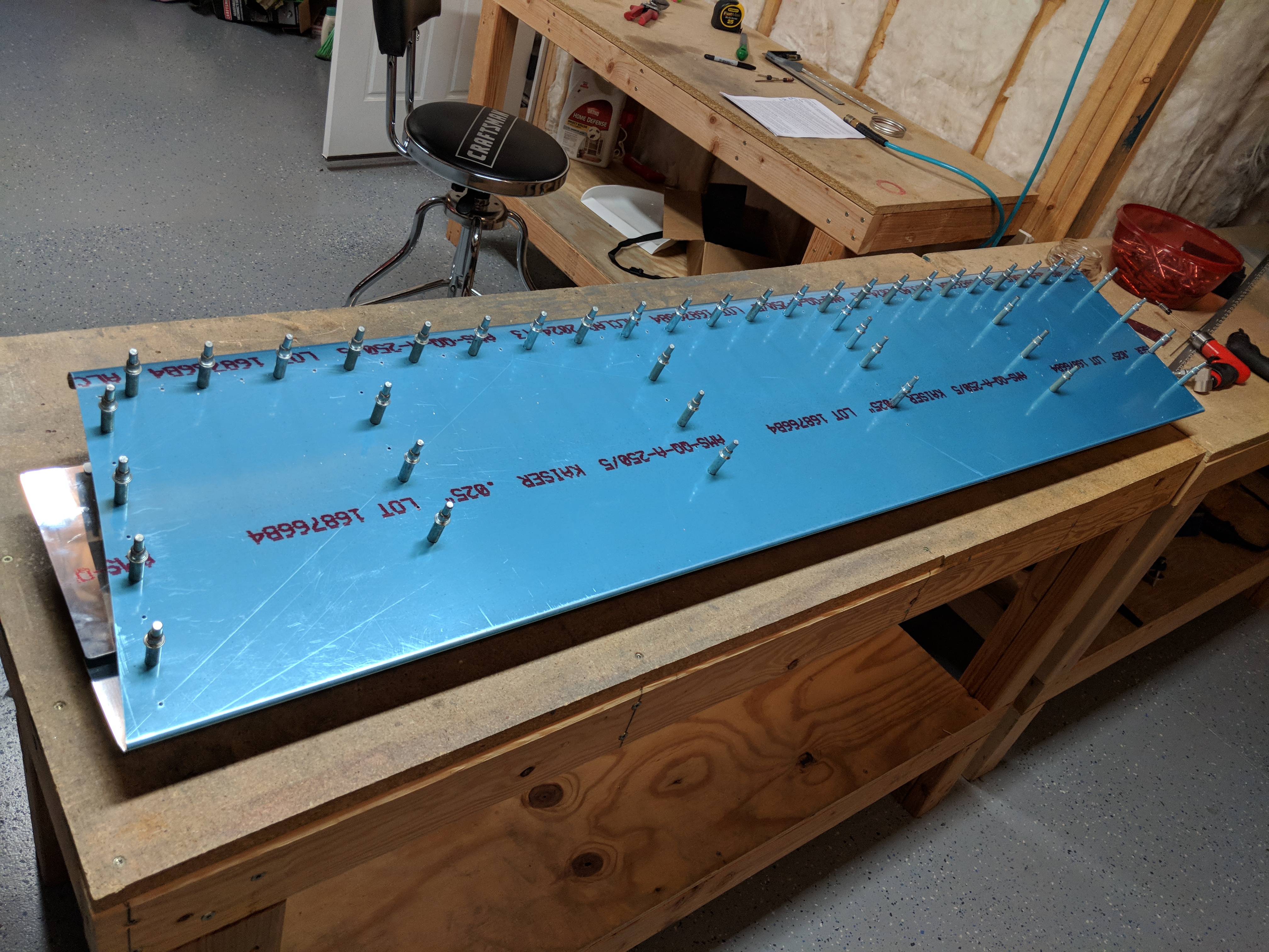
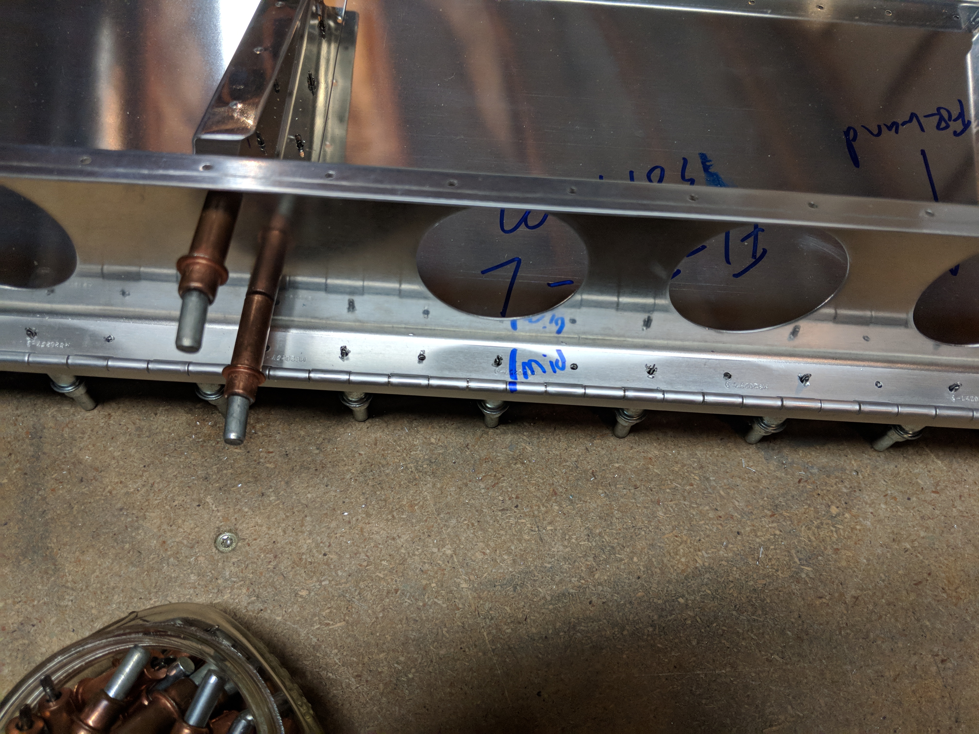
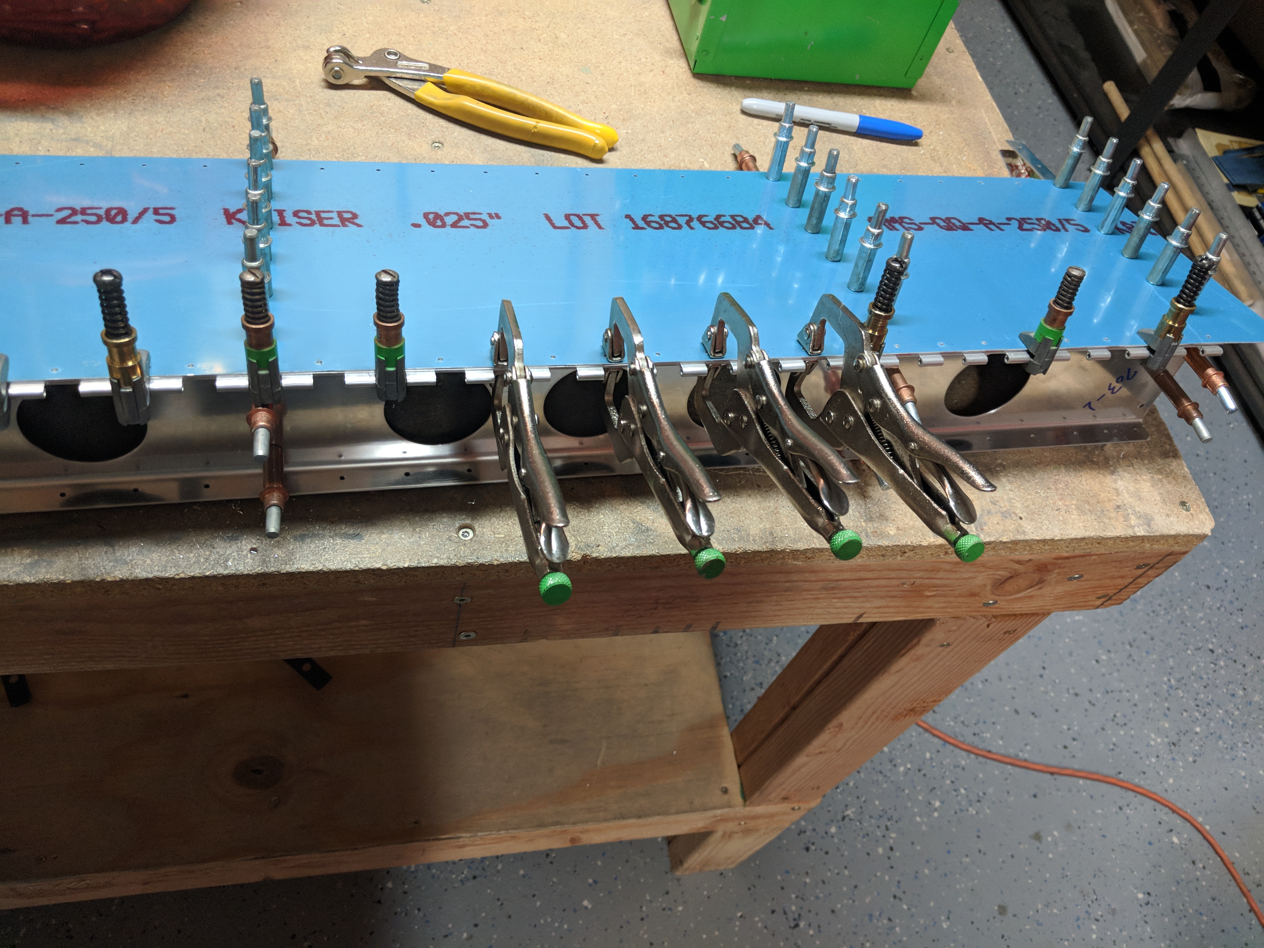
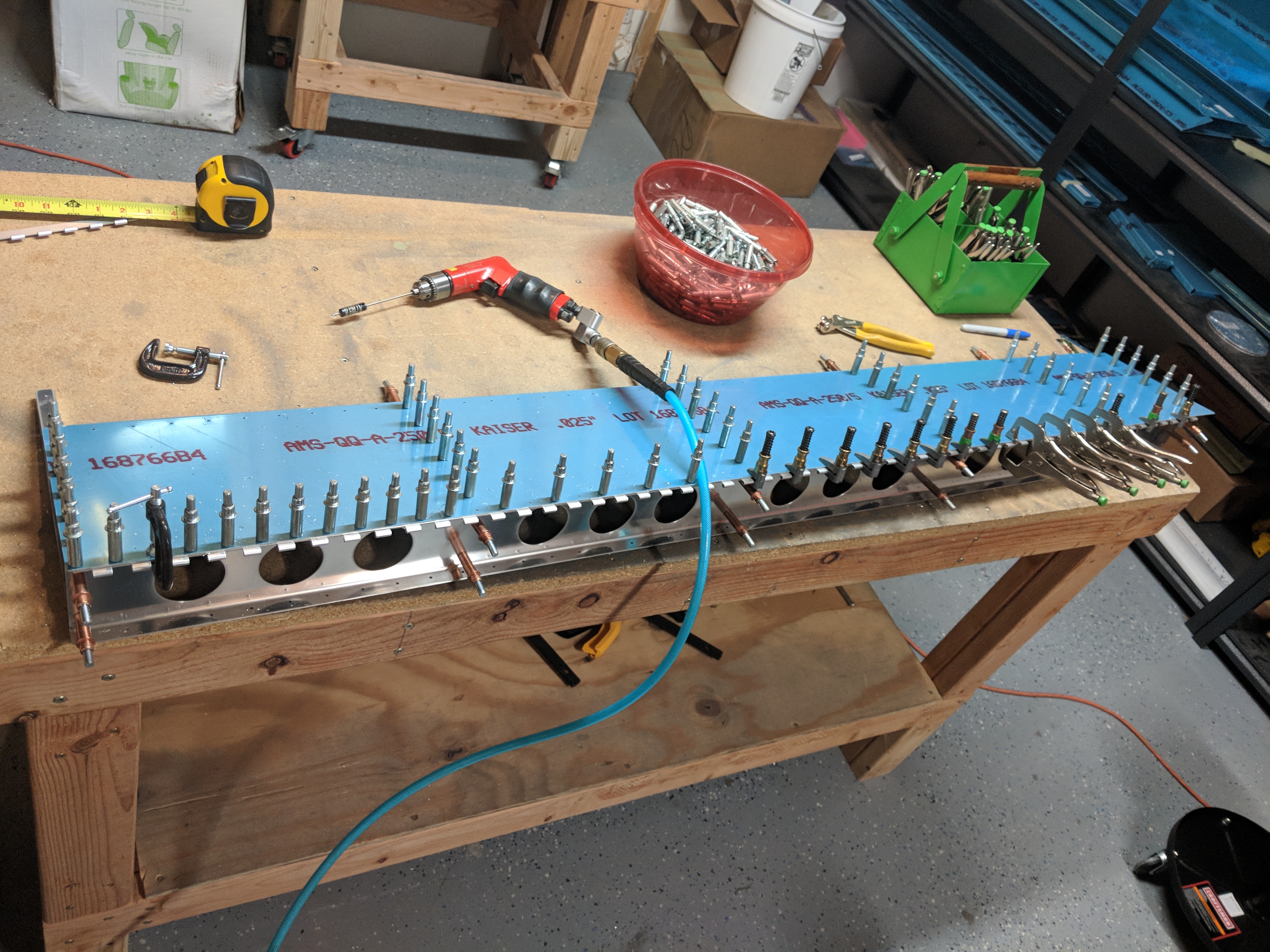
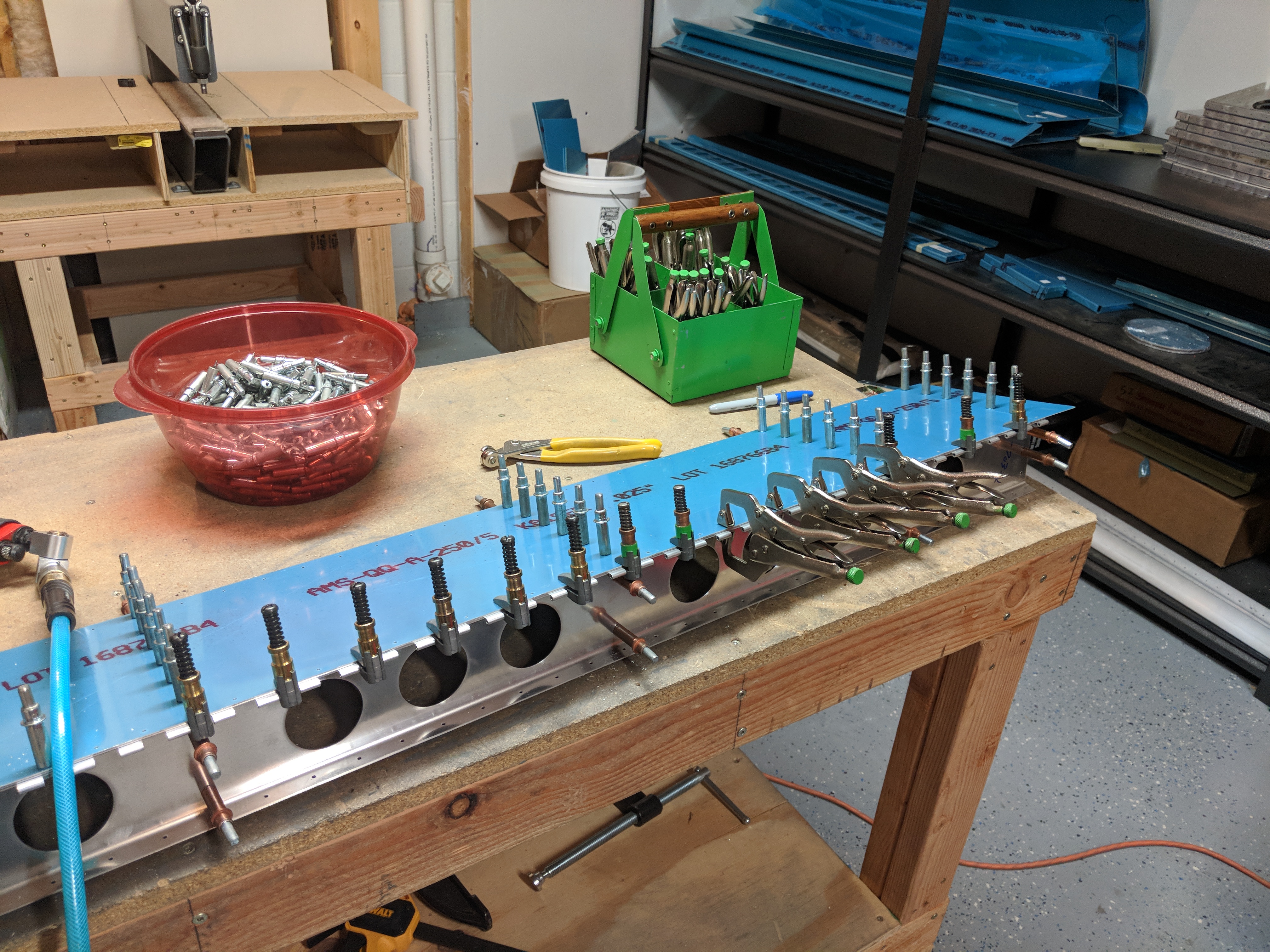
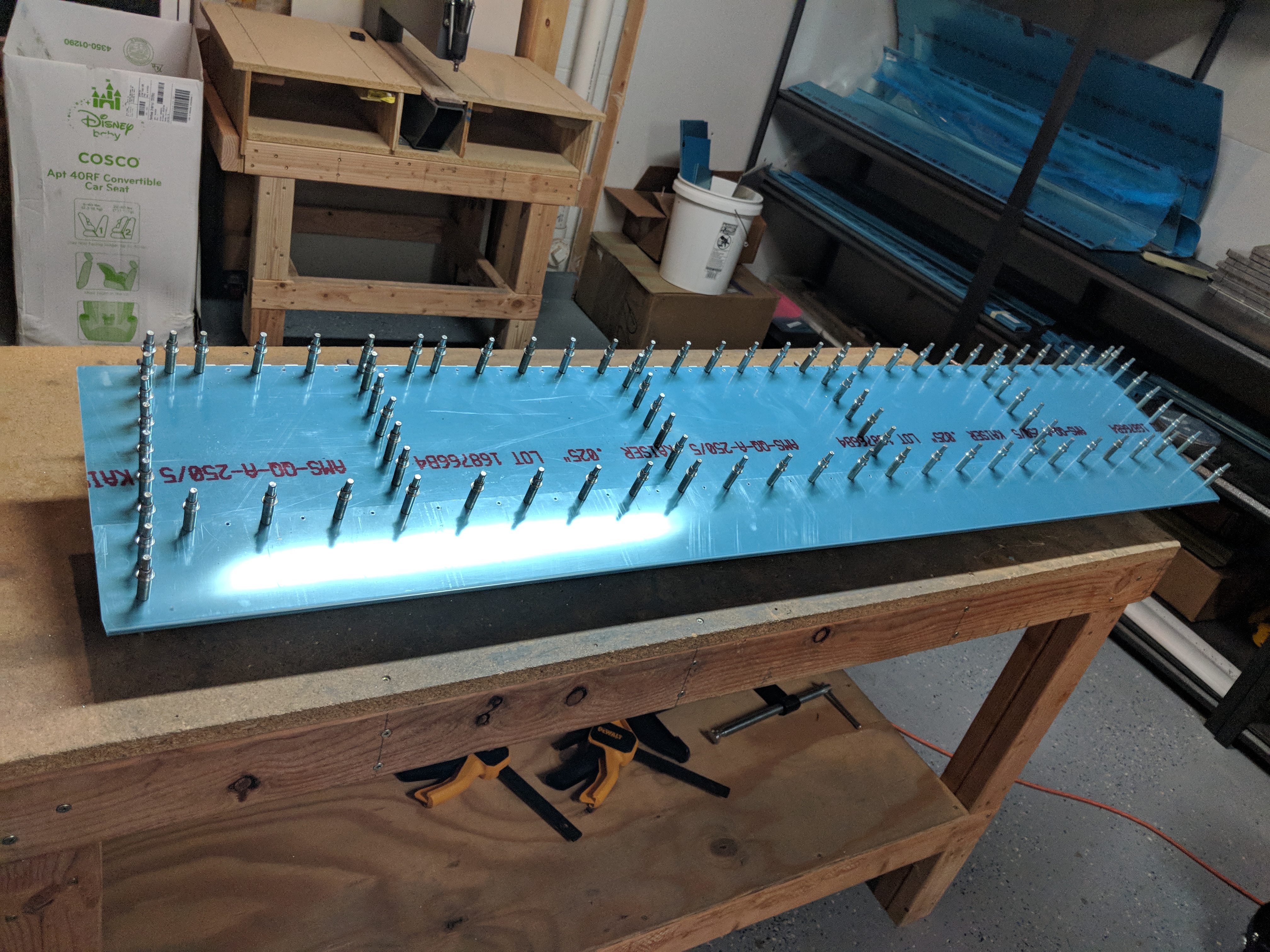
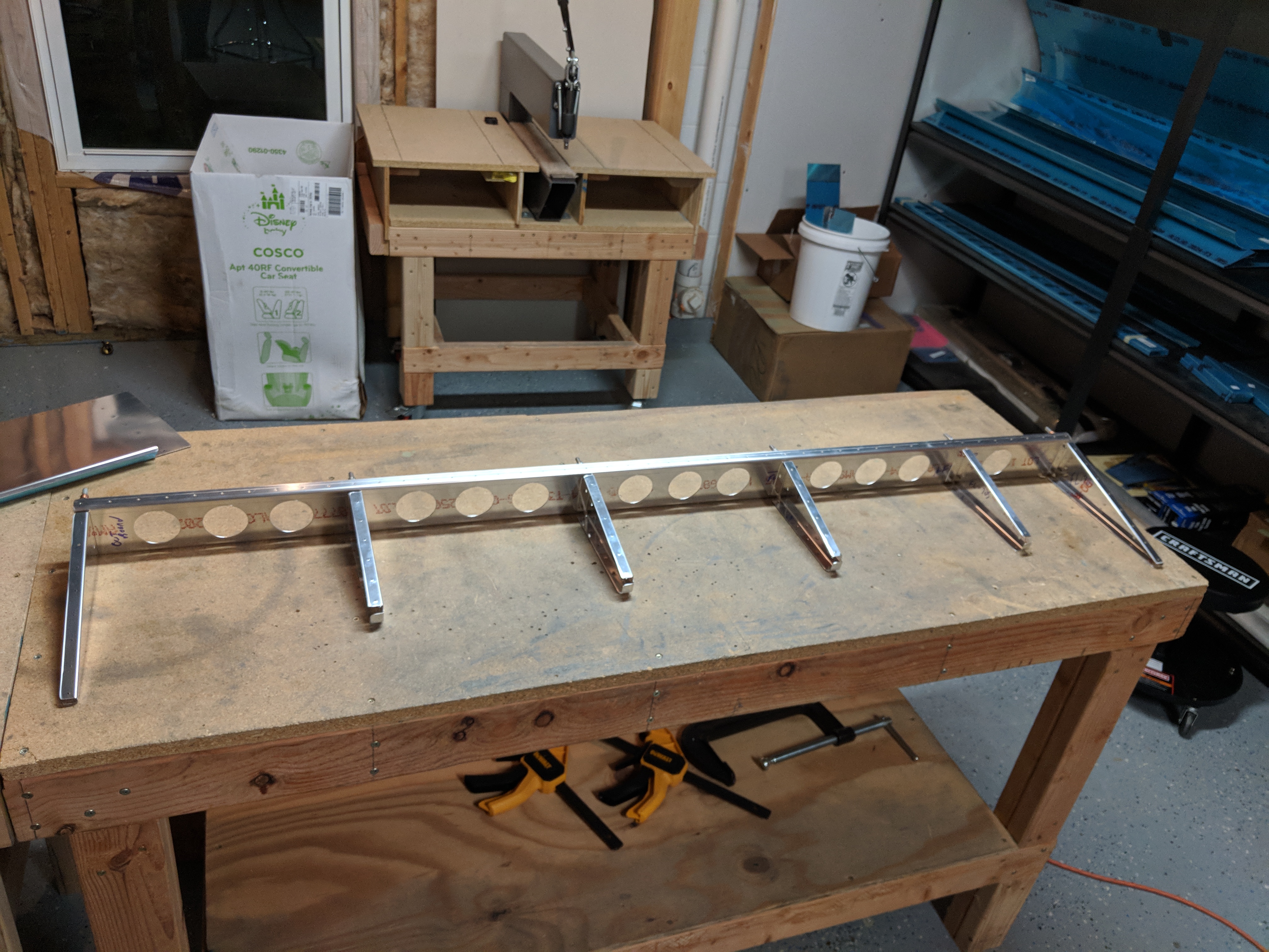
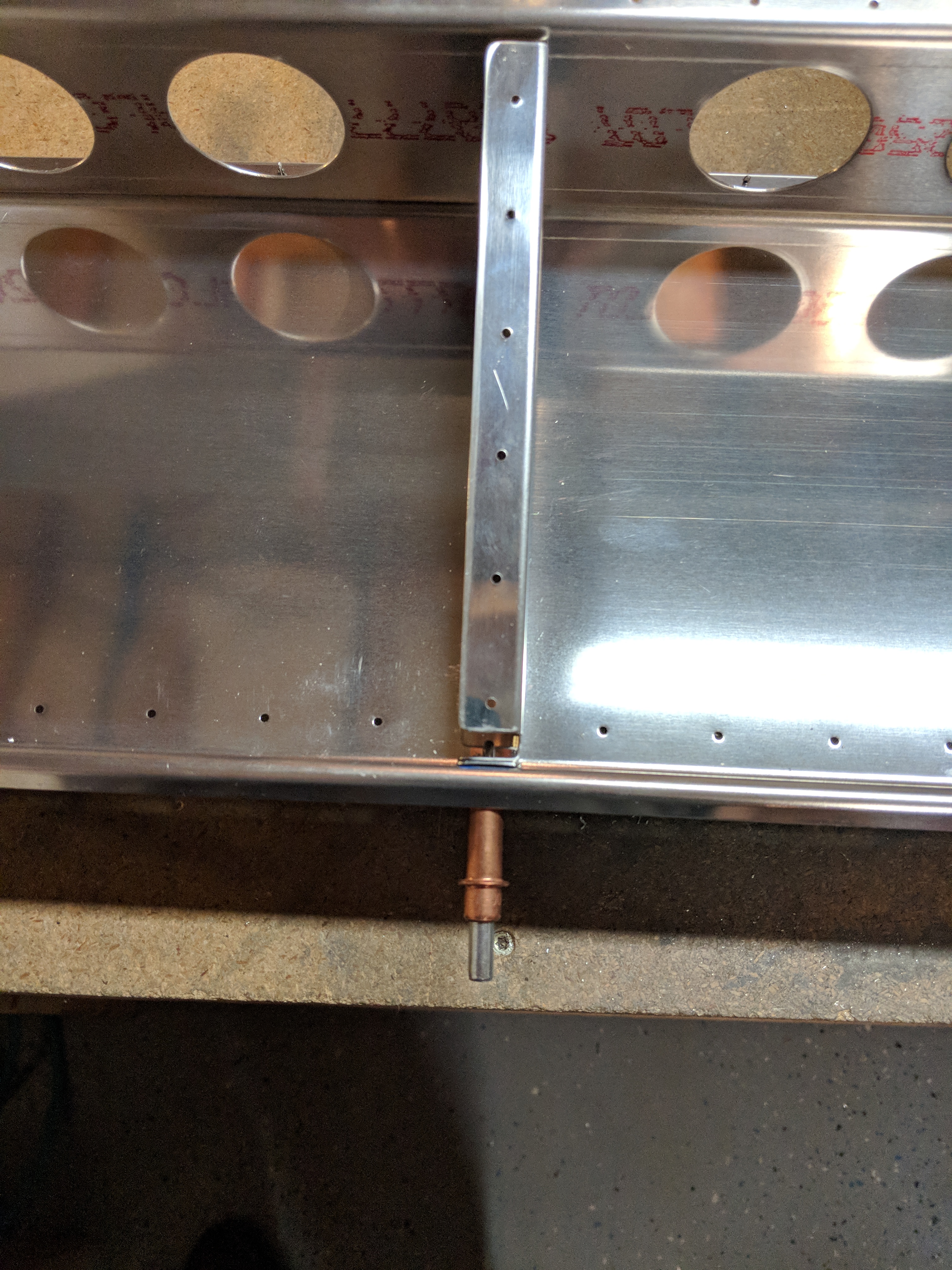
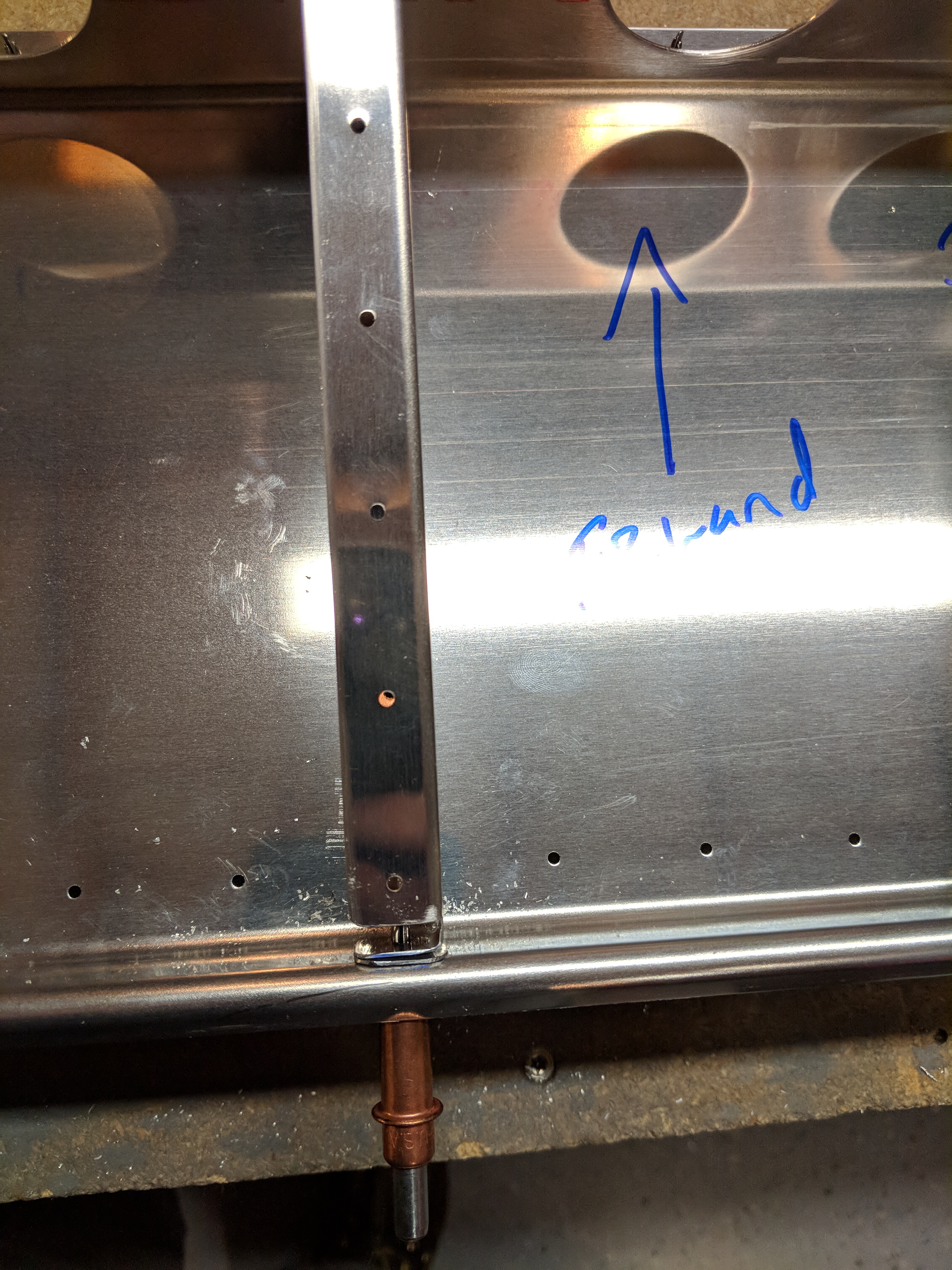
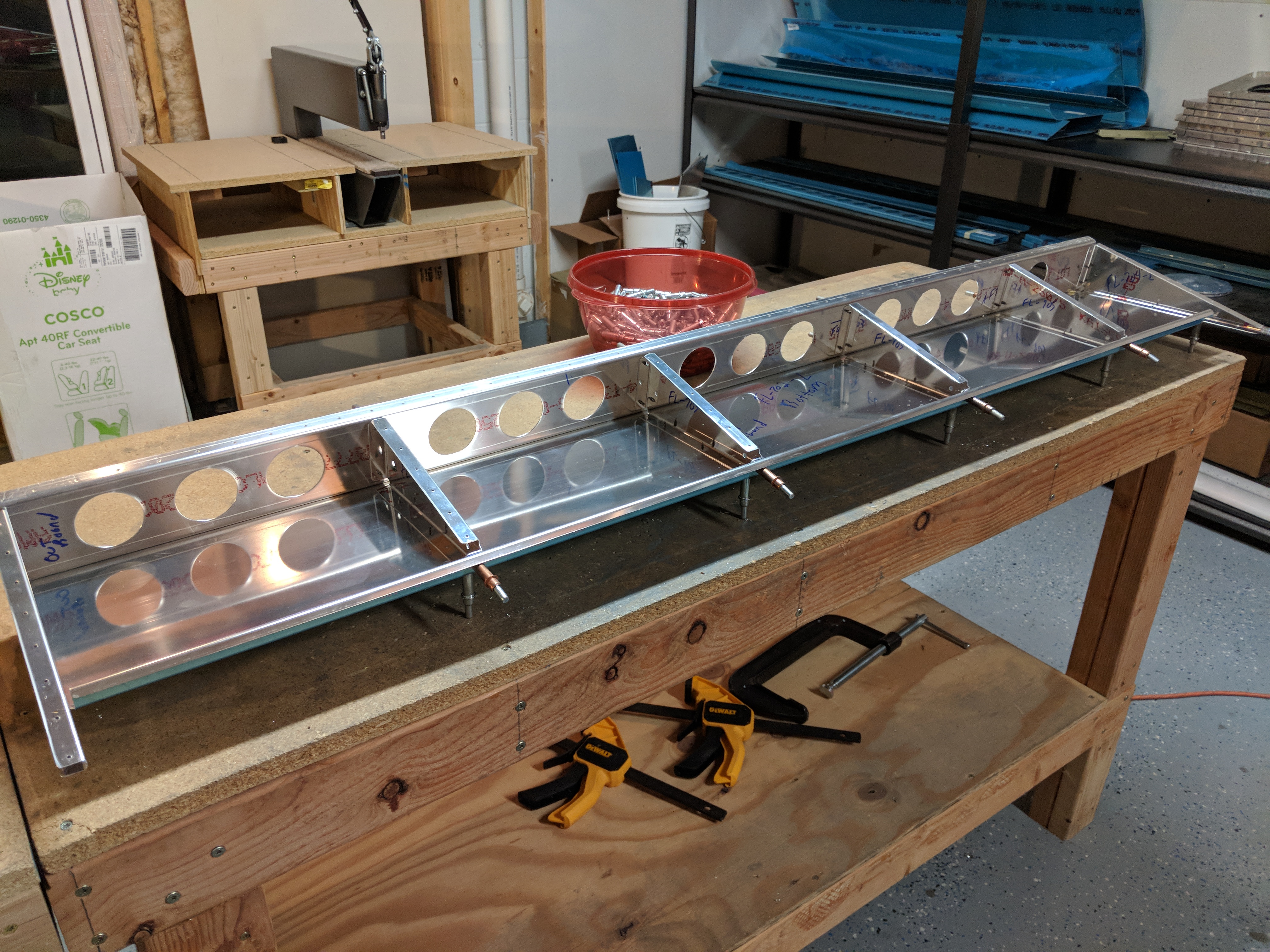
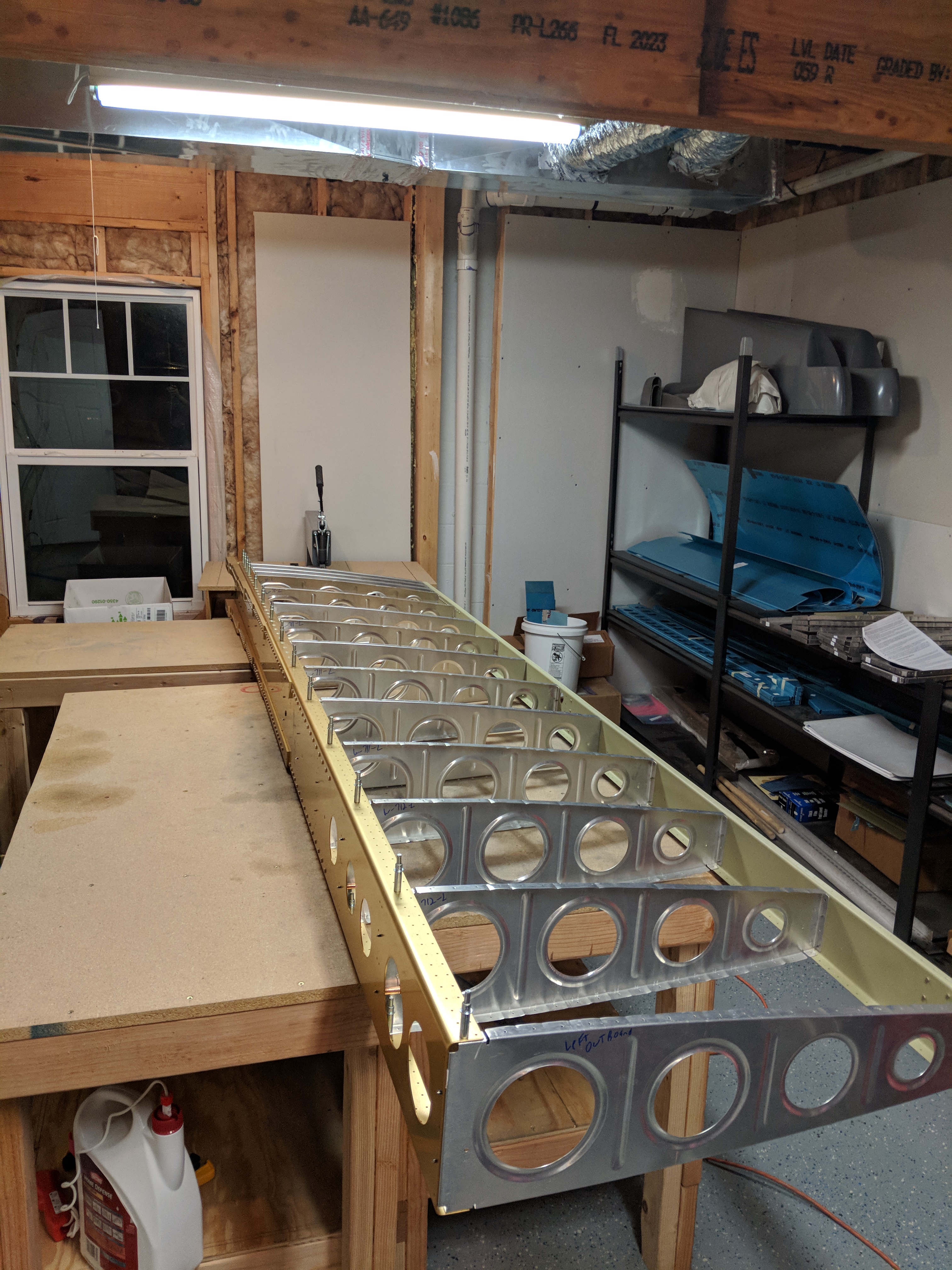
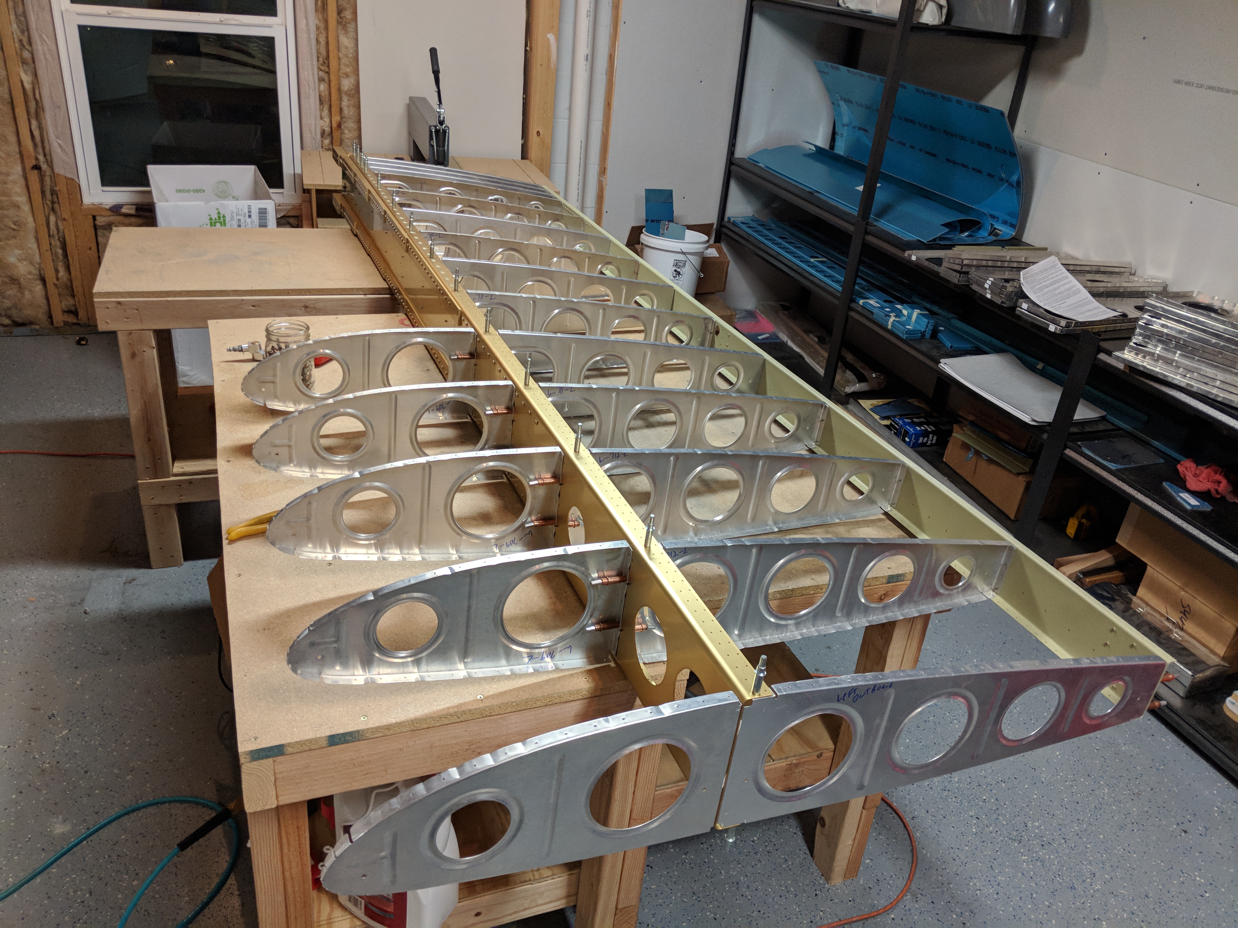
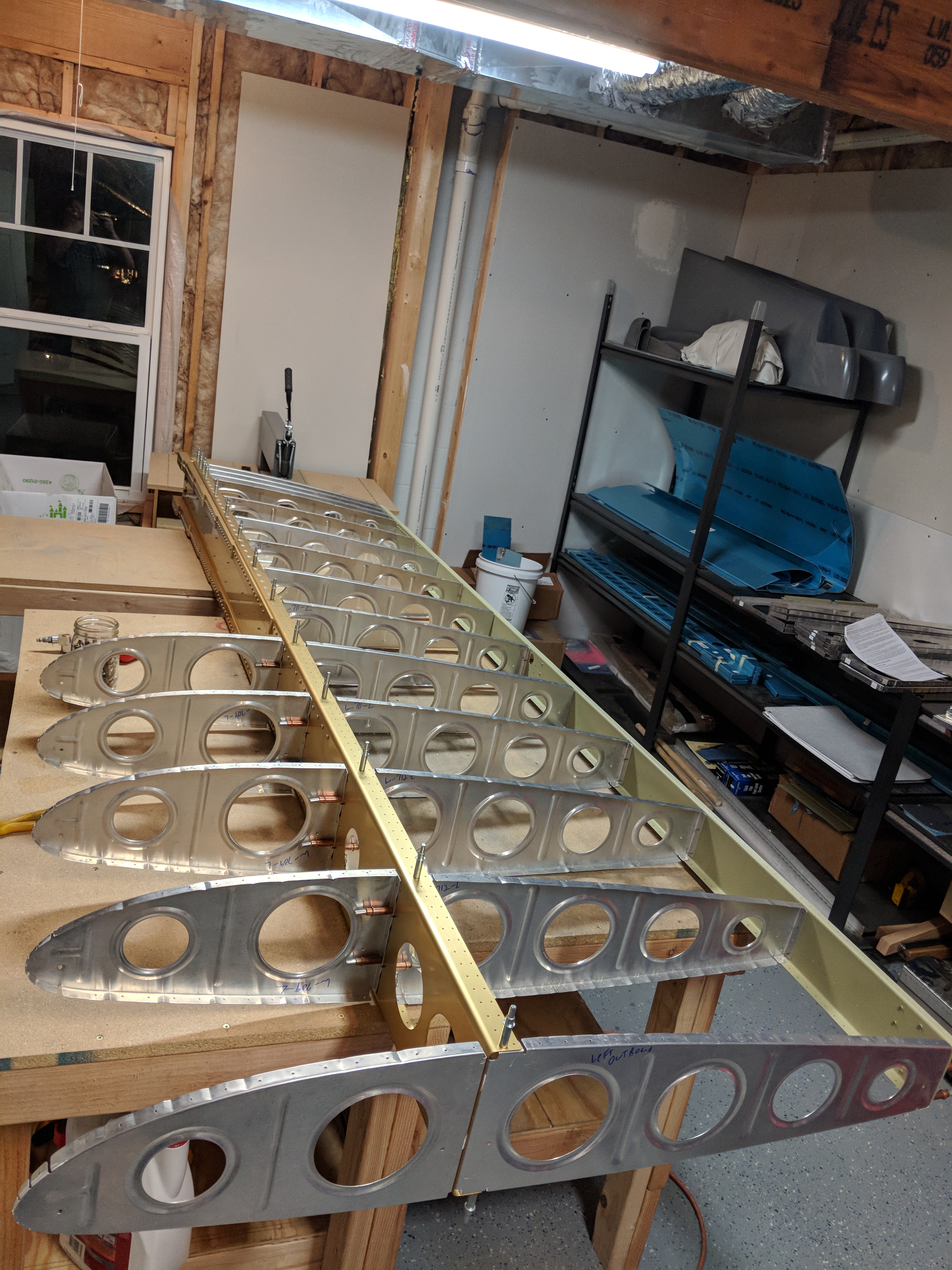
The last step for tonight was to countersink the bottom of the spar.  We are going to dimple the skin, so we need to countersink the spar to accept the skin dimple.  The reason we are not dimpling the bottom of the spar, is because we also have the hinge that gets attached to the other side of the spar flange.  Countersinking only the spar to accept the skin dimple is a much easier process than dimpling the spar and THEN countersinking the hinge to accept the spars dimple.  I clamped the spar down to my work bench to make it easier and then clecoed on the hinge.  Van’s tells us to cleco the hinge so that the hinge can act as a guide for the countersink bit’s pilot.  It actually worked out really well.

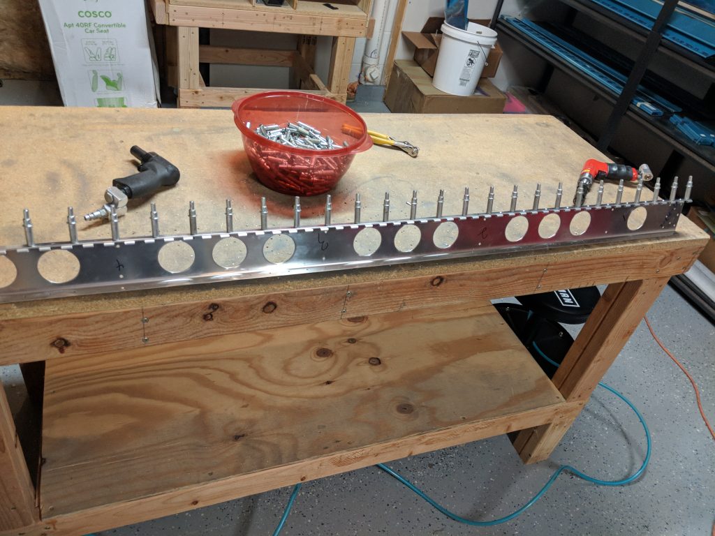
I clecoed the hinge using every other hole and then countersunk the empty ones using the microstop countersink.  I used a spar AN426AD3-7 rivet to help me gauge the correct setting for the microstop, and then used it about every fourth hole to make sure the depth is still correct. Once I had the holes done, I moved the clecos and countersunk the remaining ones.

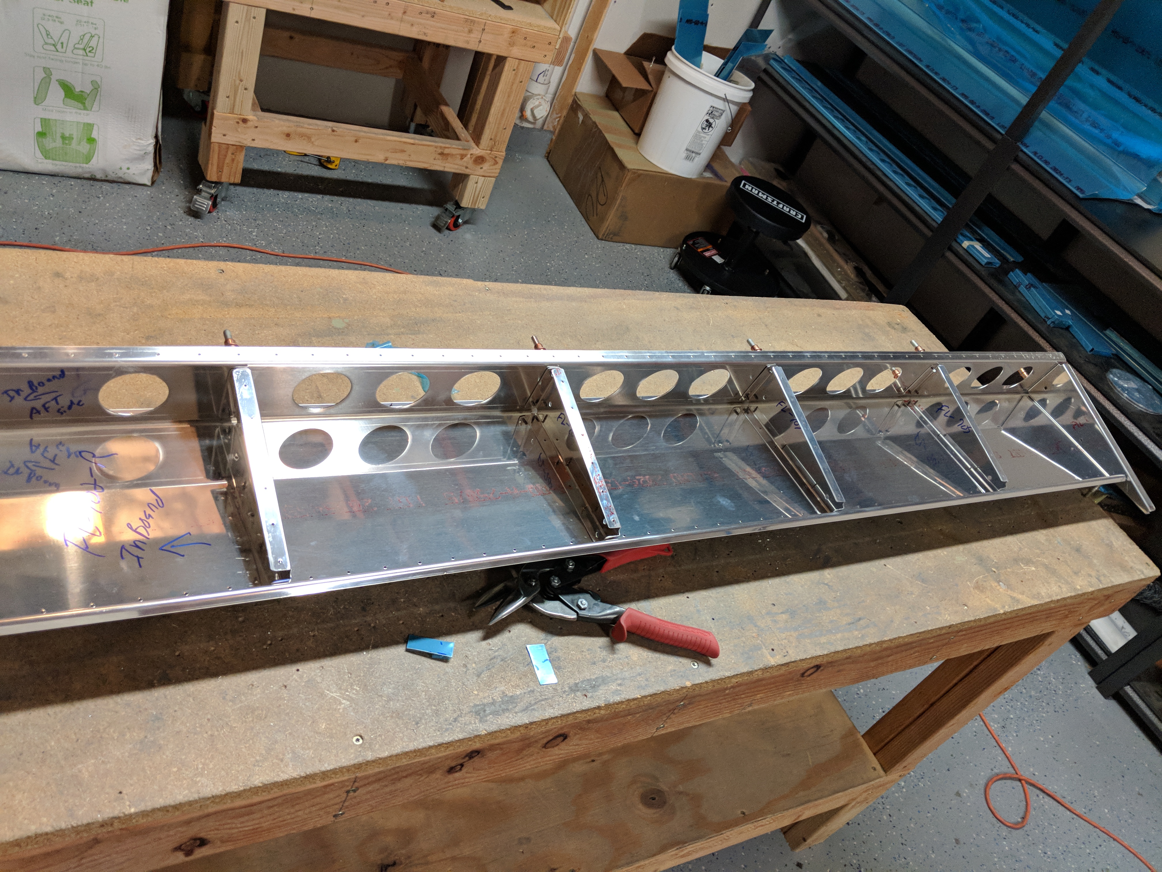
One last little step before I take the hinge off.  Vans gives us two options for the hinge pin installation.  #1: you can drill a hole in the aileron mount to insert the hinge pin through and then into the flap hinge or #2: you can remove a few eyelets in the middle of the flap hinge and cut the hinge pin in two pieces to allow room to insert the hinge pins into the flaps from the bottom of the flap. What we are essentially doing is making a left and right hinge on the flap, and making room in the middle to insert the left and right hinge pins.  This is the method I think I will go with, so I went ahead and marked my hinges where the middle is.  I will cut the eyelets when I do the initial mounting on the wing.  This way I can make sure I cut them where I have room to safety wire them down somewhere.

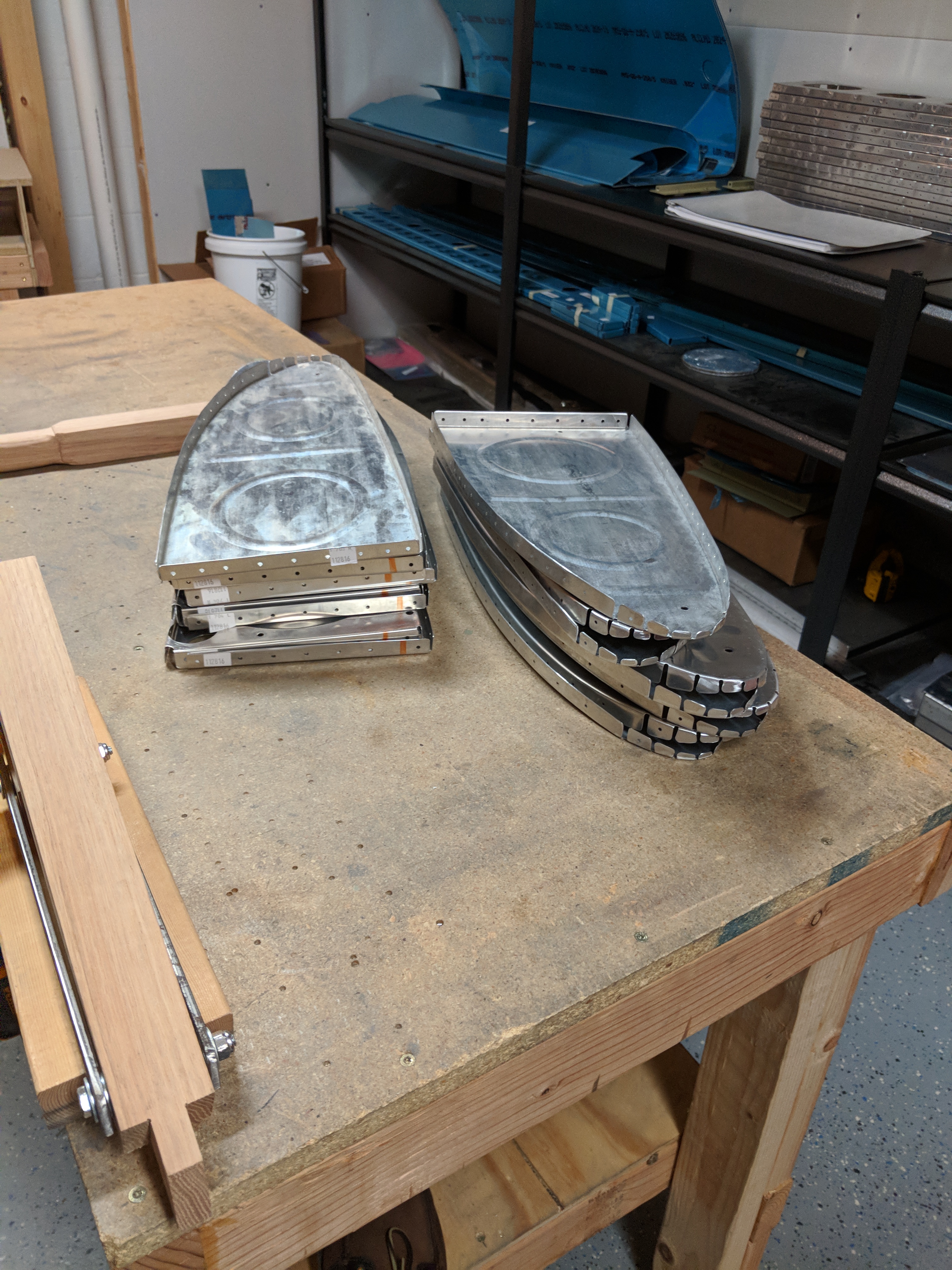
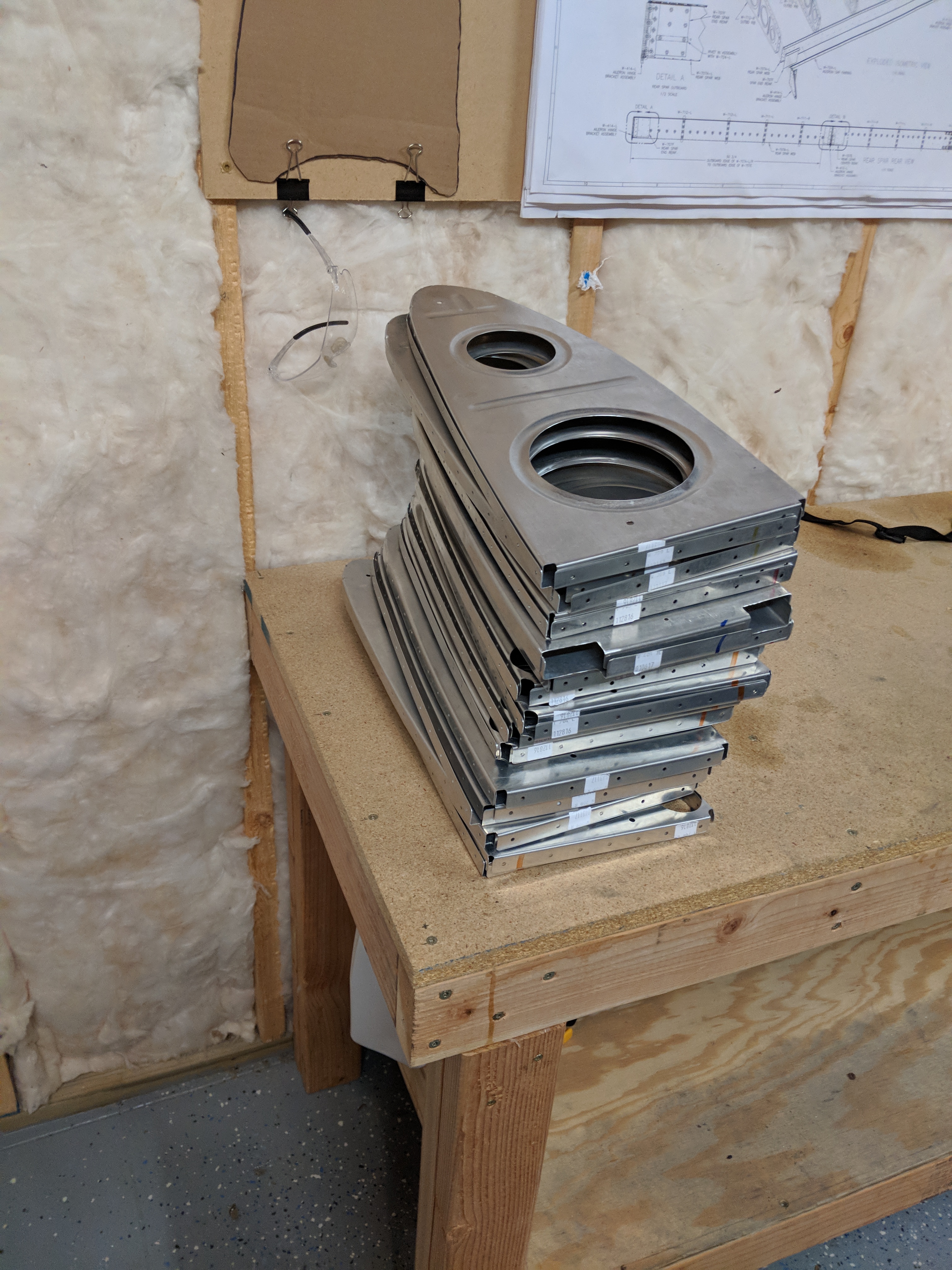
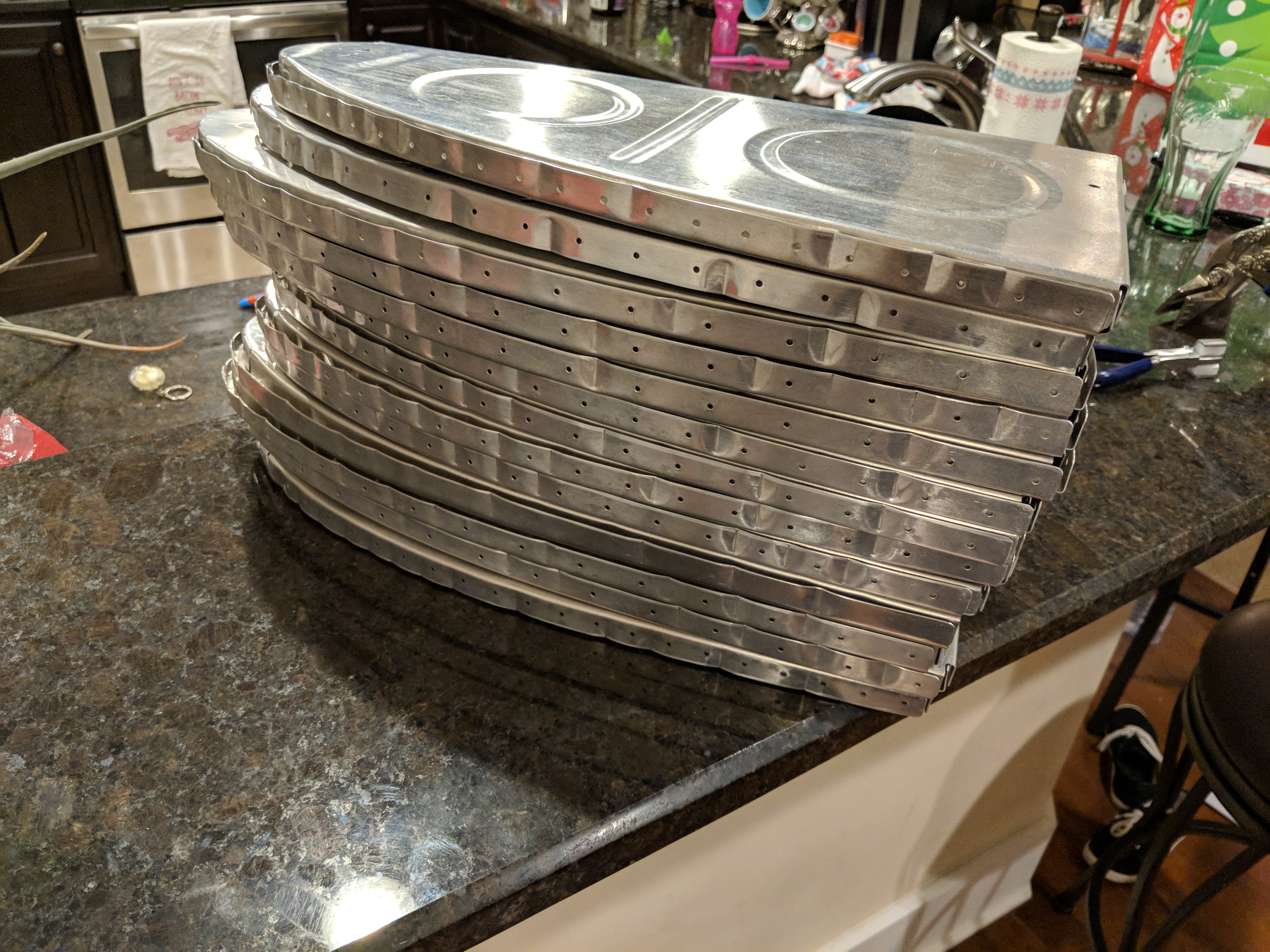
And thats all I accomplished tonight.  The left flap is ready for hole deburring, and then dimpling.  I am thinking I will wait until I get the right flap to this same stage, and then just debur and dimple all the pieces to both flaps at the same time.  From there, it will be time to prep for priming, and prime, followed by final riveting.  I am still deciding if I want to continue spraying AKZO for the wing components, or switching to just alodining them. I’ll give it some though between now and then.  Here’s all the photos from tonights work:

This slideshow requires JavaScript.


Google Photos Link: https://photos.app.goo.gl/OtSXkExzF3nicROc2

Hours Worked: 3.0

Left Flap Assembly Part 2

Tonight I continued working on the flap, with the session starting off by measuring the piano hinge for the flaps, an then clecoing it on.  I picked out the proper piano hinge, AN257-P3 and then cut it to the prescribed length of 56″.  I think Vans has us cut it about 1/4″ to short as the rivet holes are really close to the edge on both ends of the hinge after drilling.  I think I will cut the other side a little bit longer.  First off was to mark the center line of the hinge so I can use it as a sighting line in the pre-punched holes.  My marking the center (1/4″ in as per described by the drawings), I was able to see my line in the pre-punched holes and made it easier to get my hinge lined up perfectly. Next up was to mount the hinge to the bottom of the spar using some cleco side clamps, C clamps and whatever else I can find:

Thankfully, a fellow EAA Chapter 150 member lent me a few of his cleco side clamps and some nice plier style clamps.  They came in REALLY handy as I only had a few clamps myself.   After I made sure the hinge was secured and aligned properly in all the holes using my sight line, I was ready to match drill the hinge using the prepunched holes as guides.

Eventually, I had my hinge drilled and was ready to move on to the next part of the instructions:  Fitting the top skin and match drilling it.  I dug my top flap skin from the inventory, and peeled off the protective blue plastic on the inside of the skin, the slipped it over my skeleton and clecoed it down to make sure it was aligned.

Once I had it all clecoed, it was time to match drill the top skin.  The plans tell us to match drill the ribs first, then the holes on the top side/top skin next, and finally drilling the underside of the skin to the bottom last.  I am guessing this to help keep the top skin from causing a twist, so I followed as prescribed.  The skeleton is now completely match drilled to the skins!

The last few steps I decided to knock out tonight was fabricating the FL-706A braces for the spar.  These are fairly thick pieces of aluminum, made from some of the AA6-125 1.5″ x 2″ angle aluminum stock that Vans ships.  The drawings has detail on how to fabricate these bits, and they are not very complicated.  I pulled out the stock, and then measured using my machinist rule.

I used my bandsaw with a fine tooth metal cutting blade in it.  It made quick, and good work of cutting these pieces to the right size.  Then I polished and smoothed off all the edges and corners of the brackets on my bench grinder. They look nice!  After that, I drew all my indicator lines on the pieces to mark where I needed to drill my rivet holes.  I used an 1/8″ bit in my drill press to drill the 5 holes in the spar-facing side of the bracket.

Now that I have these brackets made (made 2 for both flaps), its time to fit one of the brackets to the left flap that I am working on now, and then drill the last three holes using the spar as a guide.

As you can see above, I also made some reference lines per the drawings to make sure I had that middle line lined up with the middle hole in the spar. This helps me make sure I have the FL-706A bracket nice and centered in my spar flanges. The edge of the FL706A bracket needs to be flush with the edge of the spar as well. THE vertical black line is the 3/4″ mark that I still need to trim off the bracket, I am waiting to make sure that everything lines up nicely before making that last trim.  Then I clamped it down with some C clamps and back drilled using the pre-punched holes in the spar as my guide.

Now, its time to mark and bend the Fl-706B brackets to fit the inboard rib and spar.  The drawing calls for a precise 6.3 degree bend.  The reason we do this is because the inboard rib isn’t at a perfect 90 degree, perpendicular angle to the spar like the rest of the ribs.  It bends inboard by an extra 6.3 degrees, so we need to bend the Fl-706B to match.  This bracket plus the FL-706A bracket I made earlier for a reinforcement for the rib and spar, as this is where the rod comes down to raise and lower the flaps.  That torsional torque needs to be equally spread down the spar and rib.

I have my bend lines marked and was about to bend the brackets, and then hit a snag!!!!  My stupid little bench vise is too small and cheap to withstand the force required to bend this fairly thick piece of aluminum.  It’s a cheap, small clamp on style that I am not happy with.  I tried a few times with no luck so I decided to just call it a night before I end up hurting the part or myself.  I will go and pick up a proper bench vise tomorrow, since I have been needing one for quite some time.  HEY! We all need an excuse to buy more tools right?  Anyways, thats it for tonight.  This was a solid 4+ hour work session, and I got a lot done.  Here’s the full album:

Google Photos Link: https://photos.app.goo.gl/BmvqkhwBrPEID4Z92

Hours Worked: 4.25

Left Flap Skeleton Assembly

Today, I decided to go ahead and start building the flaps.  It was a toss up between ailerons and flaps, and I didn’t want to fool with stiffeners right now, so flaps won.  I am skipping ahead to the flaps because its too cold to ProSeal fuel tanks, and I don’t want to take up valuable work room in the shop with the wing stands right now.  I read over the instructions for the flaps, and gave the plans a good study to see how they go together.  At this point in the build, Vans assumes you can make good decisions and read things so they don’t go into great detail in the instructions.  The flaps start off like any other control surface: Preparing the parts! I picked out the FL-703 front spar, FL-704-L and FL-705 ribs and the FL-702-L bottom skin and moved them to my bench.  I am doing the Left flap first, since it is the one represented in the drawings.

After stripping away the protective blue plastic on the ribs, and the inner surface of the FL-702 bottom skin, I polished up the edges of the ribs on the scotchbrite wheel, and then used a deburring tool and scotchbrite pad to polish the lightening holes in the front spar.  I went ahead and did the polishing on the ribs and spar of the right wing as well, since they are all the same parts. I figured I might as well go ahead and get them done now.  No photos of this process since its pretty much the same as my previous deburring/polishing work.

Once all the parts are polished and deburred, the plans has us start assembling the skeleton for the flap but clecoing the ribs to the front spar, and then match drilling all the holes. This is where it starts to feel like I am building an airplane again!

And of course, the obligatory selfie with the airplane parts to prove to the FAA inspector that I did indeed build this airplane 🙂

There is a section of the instructions that has us make 2 small shims that goes on the bottom of the outboard ribs.  These spacers are used to make sure that the top skin (it overlaps the rib and curves back around to the bottom)  sits nice and flush with the end ribs, and overlaps the FL-702 bottom skin perfectly. See my illustration below:

I followed the drawings and made up the shims.  The hardest part was finding the proper .020″ thickness aluminum to use for the shims.  I had to pull out my micrometer to measure the thickness of the trim bundles that Vans includes in each kit, and eventually found some scrap that would be perfect.  I then measured and trimmed out the shims per the plans.

Next up was to cleco and drill the bottom skin to the skeleton.  The skin is prepunched and lines up pretty perfectly against the skeleton.  However, as the instructions noted, it might be necessary to make some shims to fill in the space between the aft end of the ribs and the bent up portion of the F-702 bottom skin.  This bent up portion of the bottom skin actually forms what is referred to as the “rear spar” and its important that the ribs are securely fastened to this rear spar, but also not causing any deformation or bending.  I actually had to make up a few shims out of the .020″ aluminum to fit in between the ribs and the rear spar, and then drilled them using the holes in the skin/rear spar to line up.  I made sure to fully polish and round off the corners of even these tiny little shims. You can barely see these shims:

Once I had those shims made and drilled into place, I decided it would be a good stopping point for the night.  The next step is fitting the piano hinge to the flap and getting the measurements and alignment is pretty critical on that, so I will save it for tomorrow when I am refreshed.  It will be a good starting point for the next build session.  Here is the photo of my assembled flap skeleton clecoed to its bottom skin:

And here is all the photos from tonights build:

Google Photos Link: https://photos.app.goo.gl/8ourhCh3DxBuMRq43

Hours Worked: 3.5

Right Wing Skeleton Assembly and Drilling

I managed to sneak in a couple hours of work this afternoon.  Tammy was getting Acacia ready to go to “Nanas” house so we could have a date night.  So, I figured I would try to get a little work done while she was dropping the baby off.  Tonight is pretty much a repeat of last night, except on the right wing.  I managed to complete this wing a little faster than last night since I was familiar with what to do.  It seems like this will be par for the course on building the wings: Learn from one side, and then you can do the other side a little faster/better.

I started out by clecoing all the ribs the right main spar, being sure I transposed the handed-ness of the ribs.  Van’s only gives us the left side view of the wings, so they leave it up to the builder to be smart enough to “transpose” the layout for the right side.  For example, a W-709-R (RIGHT handed inboard main rib) shown on the plans for the LEFT wing, actually would be a W-709-L (LEFT handed inboard main rib) for the RIGHT wing.  Once you look over the plans and see how it goes together, its actually not as hard as it seems (trying to read from a blog post and do the figuring in your head makes it…weird. heh.).

Once I had all the ribs cleco’d to the main spar, I clecoed on the rear spar, double checking its orientation.

Now, it was time to match drill the main ribs to both the main spar and rear spar.  That was simple enough, and didn’t take too much time.  The last thing left to do was to cleco on the leading edge ribs, again, double checking the orientation and proper handed-ness and then match drill them as well.

VOILA! I have another piece of kit that looks like a wing should look! I still haven’t fully decided on what to do for wiring, but I still have some time.  However, I think I may actually move on for now and start building the flaps and ailerons and leading edge skins.  Its currently winter time in Tennessee, so my workshop is hovering around 60 degrees, which can making working with ProSeal (for the fuel tanks) and bit challenging.  Spring and summer are only a few months away, so I will hold off on my fuel tanks until warmer weather.  I am also considering doing the same for the wing stands.  I think I would like to build the control surfaces while I have plenty of room in the shop. If I build the wing stands, I will loose a good bit of working area in the shop, so I will ask the experts on Vans Airforce if there are any gotchas to skipping ahead and building the control surfaces ahead of the stand and tanks.  At any rate, here is all the photos from todays build session:

Google Photos Link: https://photos.app.goo.gl/Bx5tJyDEThlWKNPu1

Hours Worked: 2.5

Left Wing Skeleton Assembly and Drilling

After completing all of the rib prep, I was finally ready to start doing the skeleton assembly and match drilling for the wings.  The plans tell us to be very cautious of not using tank ribs for leading edge ribs, so I made sure to sort out the two and set the tank ribs to the side.  Then, I took several minutes studying over the plans to make sure of the proper orientation of the ribs, and picked out the parts I’d need to complete one wing.  I figured I could get one wing completed tonight, and do the other tomorrow night.  I am a bit confined when it comes to work tables and space to build the two wings at the same time, at least until I build my wing stands.

I started with the left wing, since that is the wing that is depicted in Van’s plans.  This way I wouldn’t have to worry about transposing the plans for the other wing on my first attempt.  The instructions tell us that the ribs have a left and right handedness to them, and explains how to determine which is which.  The plans also denote the handedness of the ribs, so it was easy to match up.  I pulled the main spar from its storage and moved my workbenches around to give it good support.  Then I methodically picked the proper rib, double checking it against the plans before cleco’ing it into place.  Eventually I had all the inner ribs clecoed to the main spar, and a wing form was starting to show up a little:

Next up was to fit the rear spar to the skeleton so I moved my benches around a little more to accommodate it and clecoed the rear spar to the ribs, making sure I had the proper orientation. The wing box is starting to come into shape!

Now, it was time to attach the few leading edge ribs to the front of the main spar.  Again, I referenced the plans and made sure I had the proper part number in the proper orientation and then clecoed them onto the main spar.  Finally!!!! Its starting to look like I am building an airplane again! Its really rewarding to see the wing start to take shape after spending so much time on prepping the ribs.

The big empty space left on the main spar in the background is where the fuel tank will attach, and I won’t build it until a few more sections later in the plans.  For now, I match drilled all the holes in each of the ribs to their final size. Then I disassembled the wing, taking the time to number each “station” of the ribs so that I can fit the exact rib back in its original location.  This may be overkill, and not needed, but I figured I might as well go ahead and label each station just in case.  Once I had it all disassembled, I vacuumed up all the chips from the main spar, and set these ribs to the side for deburring at another time.

Now, I need to decide what to do about wiring looms/harness/conduits. The driving reason, is that I need to drill the holes for the wiring and any conduit that I plan on using now, before I prime these ribs for final assembly.  I am still leaning towards following the Vans approved rib drilling guide found here:  https://www.vansaircraft.com/pdf/Wing_Wiring.pdf and using the Vans conduit for the bulk of the lighting, strobes, heated pitot and stall warner wiring.  Then opening up the tooling holes as prescribed in that guide for the coax for NAV antennas.  I’ll put some thought to this over the coming days, and may even try to do a wiring schematic.  Thats it for tonights session.  About three hours total, and I have a fully assembled, drilled and ready left wing skeleton. Entire photo album is link below from tonights build:

Google Photos Link: https://photos.app.goo.gl/JqnmnU1zEfnZ2qR02

Hours Worked: 3

Leading Edge Rib Straightening and Fluting

4 months.  Thats how long it has been since I have done any major work on the RV-7.  Between work and family and then holidays, I really haven’t had much free time to get down to the shop and build.  Having some time off for the holidays, I decided to put work and learning aside for a few nights while I am off and get some work done on my build.  I only have a few ribs left to straighten and then flute, and they were the leading edge ribs.

These guys were a bit more tricky because of the curve on the leading edge, and I had to refactor my flange straightening tool so that it had a smaller “bite” to allow me to not mess up the very nice and sleek compound curve in the top of the leading edge.  You can see how much smaller the anvil is on my flange bender in this photo:

In the bottom left of that photo, you will see the new anvil I cut from some spare oak I had left over from the first, wider, anvil.  This worked great, and didn’t cause any warping or mis-shaping on the top curve.  I did all the rib straightening down in the shop on my bench, and then moved my stack of ribs upstairs so I could use my wifes granite counter tops as a perfectly flat surface to do my fluting to bring the ribs back into flat.

Heres my finished stack of leading edge ribs, with their perfectly 90 degree flanges, ready for fluting. Notice how much warping there is from the forming process.  This is why we flute the ribs:

And after about an hour and a half of fluting, I ended up with a nice flat stack of leading edge ribs.

Some needed a bit more than others, but they are much straighter and flatter now.  I might have to do a little more here and there once I start mounting them on the spars, but I’d say I was able to get them 99% of the way ready.  FINALLY I have all my ribs done.  All the flanges are at 90 degrees, and they are all fluted to be as true as possible.  This was probably the most boring work I have done so far, and I am SOO SOO glad I can move on to something else.  Heres all the photos from tonights session in one album:

Google Photos Link:  https://photos.app.goo.gl/0DF6VPiHYHkbKkjQ2

Hours Worked:  3.25

Wing Rib Fluting — Part 2

I found an hour or so to finish up the main wing rib fluting.  Like the last session, I used the table top method on our granite countertop and knocked out the remaining 14-something main wing ribs.  They stack much nicer now that they are all formed straight and with proper flanges.

I was going to start working on the leading edge ribs, but decided to hold off on those guys, because I think I will modify my flange straightener tool to work with these curved edges so I can more easily get the flanges to 90 degrees.  Then I can flute them all.  No photos from tonights work, as it is pretty much the same as the last session.

Hours Worked:1.25

Wing Rib Fluting — Part 1

About a week ago, I decided to bring my wing ribs upstairs and do the fluting up here, since that doesn’t produce any filings or shavings.  HOWEVER….I have had a lot going on family wise that I haven’t been able to spend much time on them.  I’ll also admit that over the last few days I have actually been fiddling with these things to the point of frustration.  I tried a few times to sit down and get the straight using the wood dining room table as my “flat surface”, and always end up frustrated because no matter what I tried, they never would come out straight.

You see, we have to flute  the flanges on the ribs because during the forming process they will get bowed a bit.  Fluting “shrinks” the metal down along the flange, pulling it back straight.  See how they are from the factory:

It seems like a simple process, and it actually is…..if your reference surface is truly flat.  😐  Turns out, our dining room table is not exactly flat, and I was using this bowed/curved surface as my guide and my ribs never came out right.  Once I realized this, thanks to my wife Tammy, I decided to use our granite counter tops, since I knew they’d be nice and flat.  After switching over to the stone counters, I ended up using the “table top” method of rib fluting.  This video shows how to do this method: https://www.youtube.com/watch?v=pIvFpVV6kIQ

The results speak for themselves.  After I did the table top method, with the flanges sticking up I flipped the rib over with the flanges down towards the counter top to double check.  Then I used a metal ruler to measure that the rivet holes were all in alignment.  Some ribs (like the one below) only needed a couple of flutes, while others needed many more.

I ended up getting the process down pat, and was able to knock out 14 ribs using the granite counter to and “table top” fluting method.  I did have to go back and re-do the ribs that I did on the dining room table, since they were not straight.  I’ve got a lot more to go, but I think this method will help me knock them out quickly. Here’s all the photos from tonight’s work:

Google Photos Link: https://goo.gl/photos/pc9q3jqyrzesHnzn9

Hours Worked: 2.75