Assembling the Right Aileron

Tonight was pretty much a duplicate of last night.  I started out by assembling the leading edge and the trailing edge skins to the skeleton and match drilling everything. Making sure to drill out the holes along the bottom to a #30 hole where the skins overlap the spars. Once I had both sides match drilled, I flipped it over to finish the work.

Next up was to drill the counterbalance pipe using the leading edge skin as a template.  Learning from the work last night, I used a #40 drill to first drill the holes in the counterbalance, and the opened the holes up to a #40 size.  After drilling into this steel, I believe my drill bit is finally getting dull.  I’ll finish up the ailerons and then replace it.

( That photo doesn’t show very good, but thats a 3/32″ cleco in that hole…it looks like a giant hole from this angle heh )

Now its time to remove the trailing edge skins and re-cleco the leading edge skins to the spar so I can drill the last two holes in the counterbalance pipe.  Just like last night, I used my long drill bit, and went in through the lower mounting hole in the nose rib to back drill the counterbalance and that went well on both sides.

With all that, the right aileron is ready for deburring and edge finishing.  So far, I had only worked about an hour, and I was still ready to get some work done, so I went ahead and started deburring the holes in the parts for the right aileron.  I was able to get all of the skeleton parts holes deburred, and all I have left is the skins.  BUT, I need to remove some of the blue plastic before I do that.  So, I’ll save that for tomorrow.  Here’s all the parts I was able to get the holes deburred on.

That wraps up tonights short work session. I am still working on a few things for my job, so I don’t want to sink to much time in to each nightly build session.  Hopefully that will change soon.

Google Photos link: https://photos.app.goo.gl/RDvsOnVtc6D38a9g2

Hours Worked: 1.5

Assembling the Left Aileron

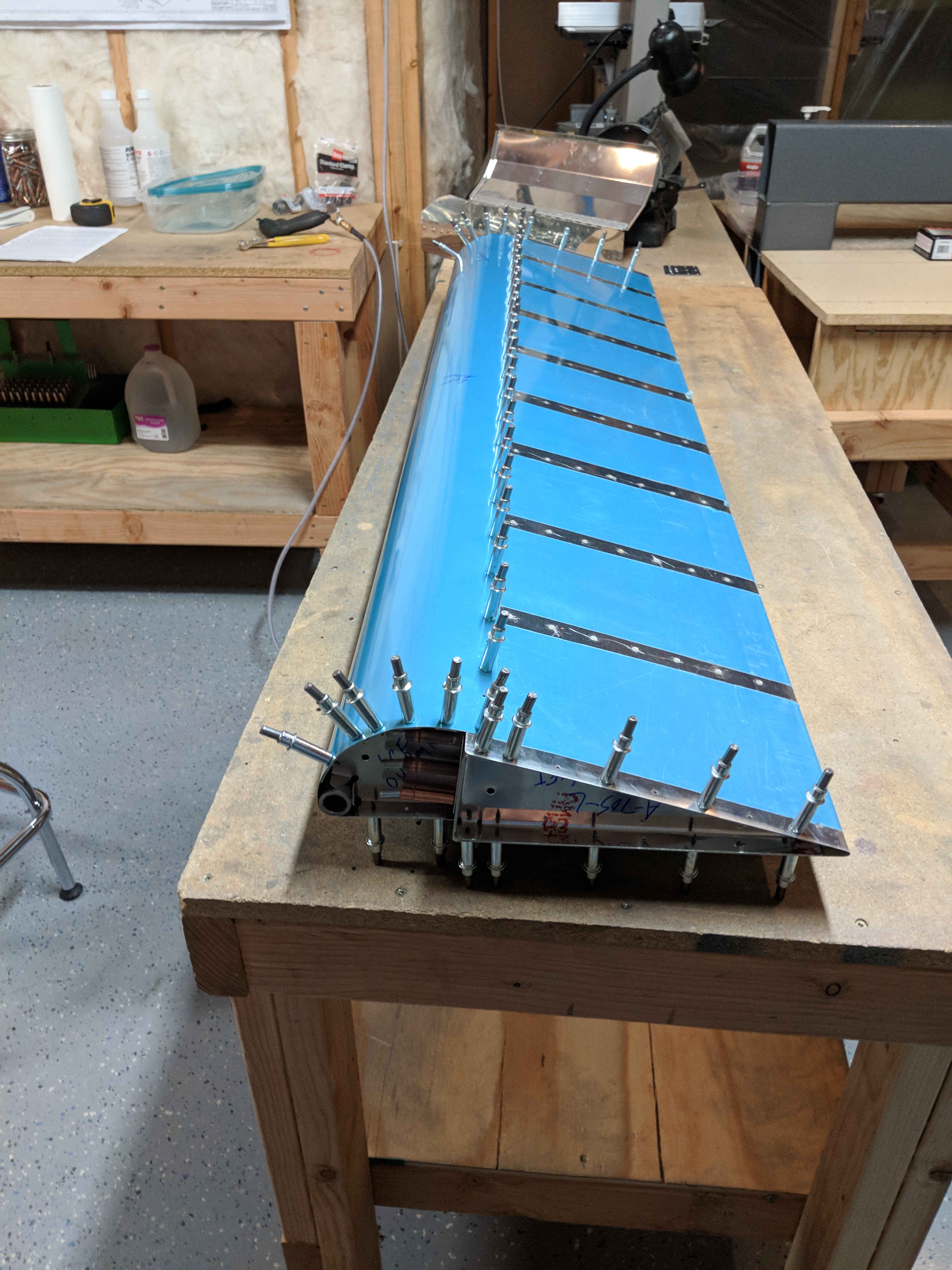
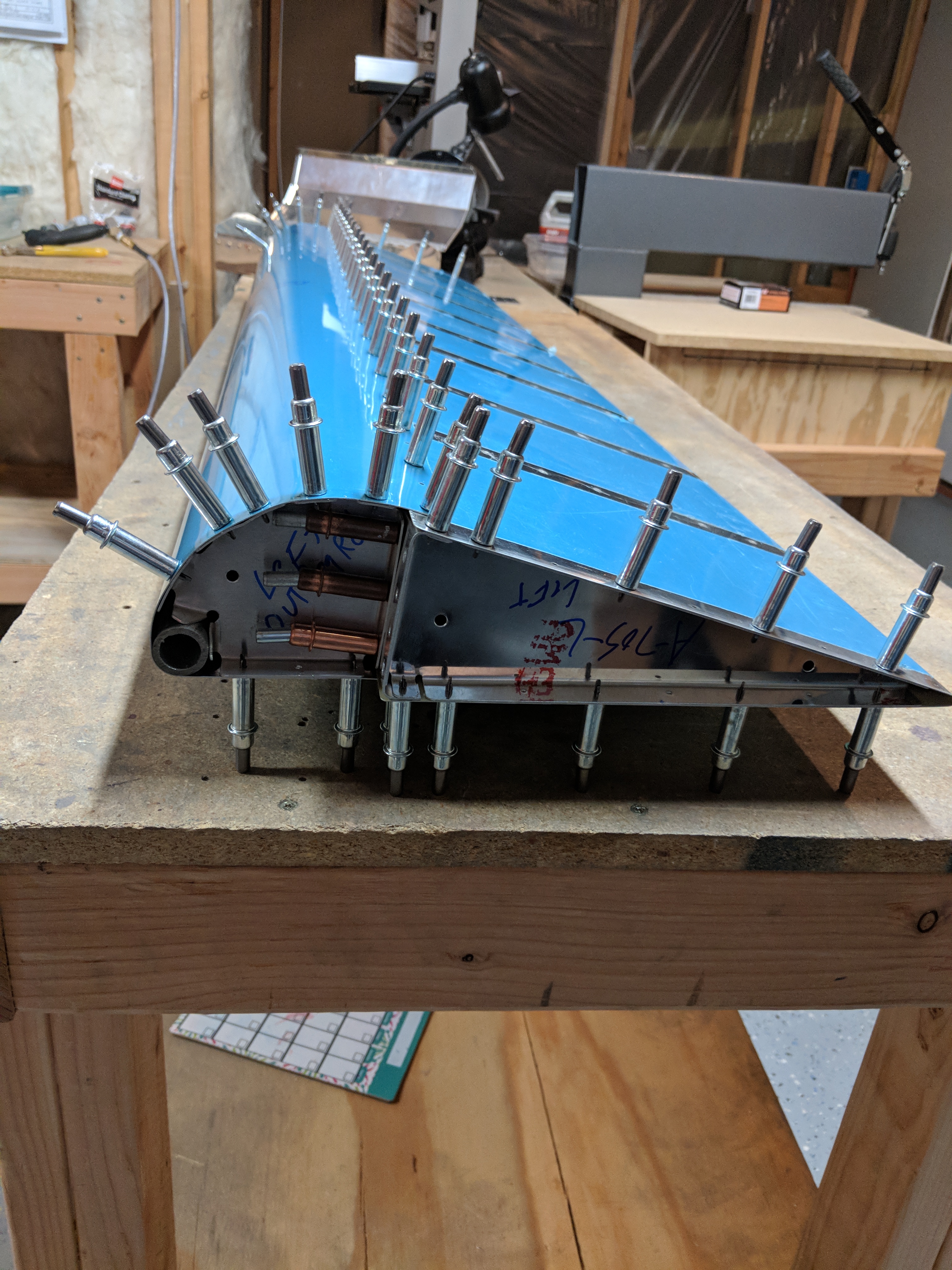
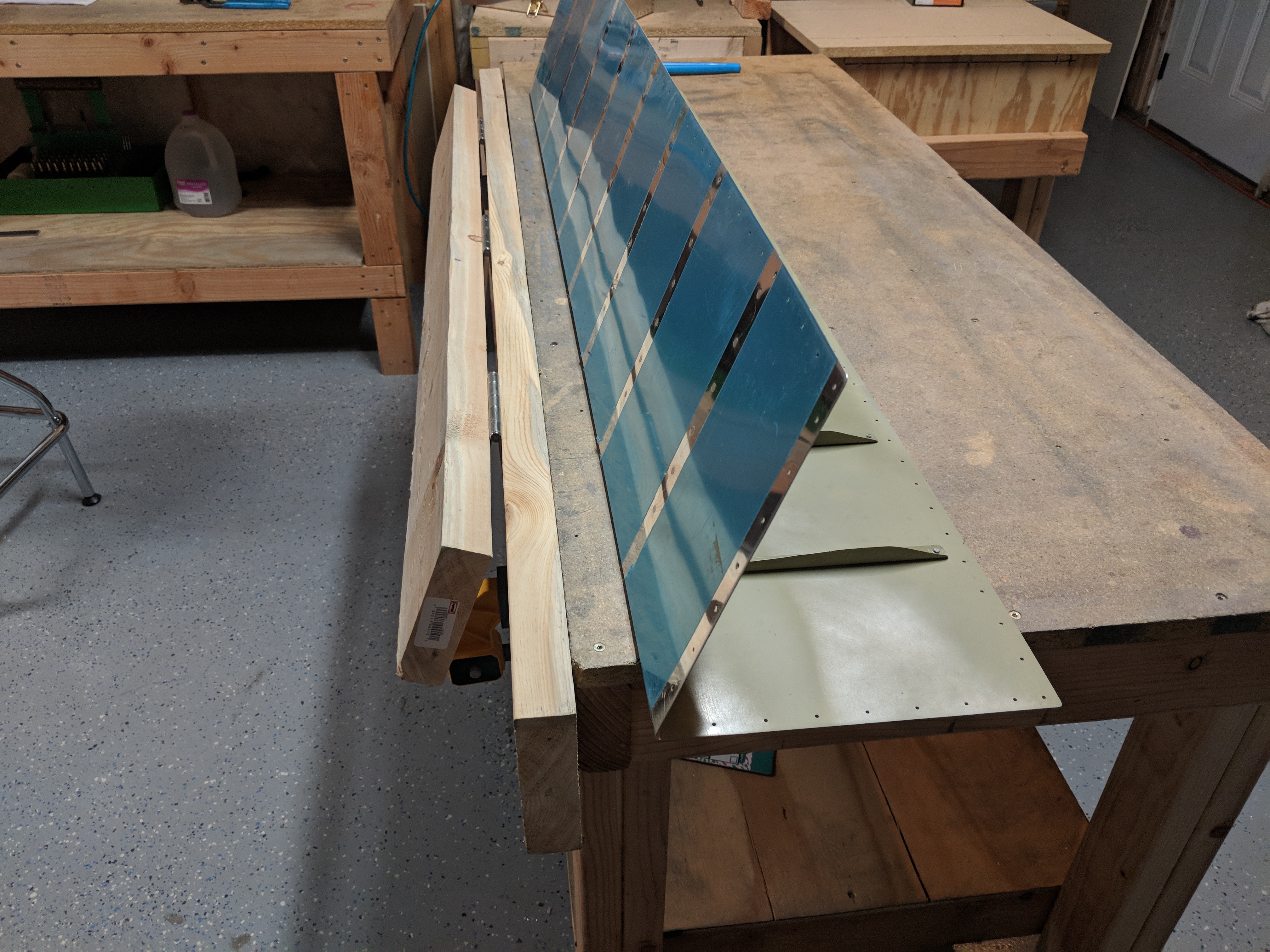
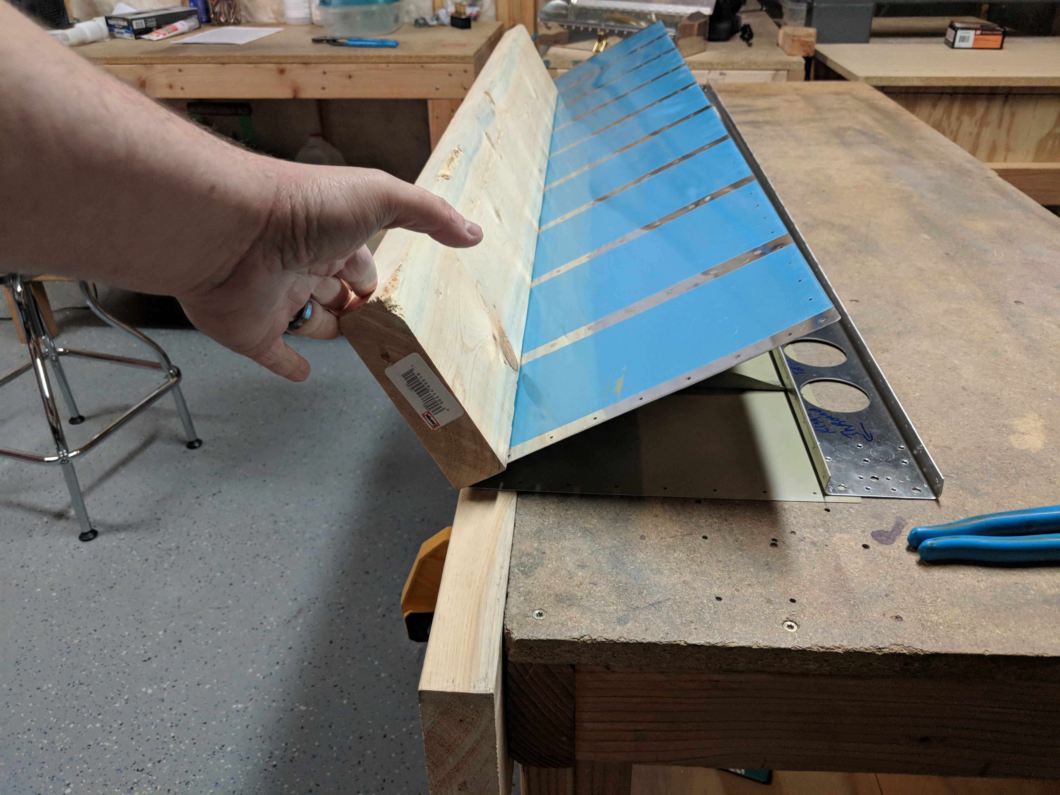
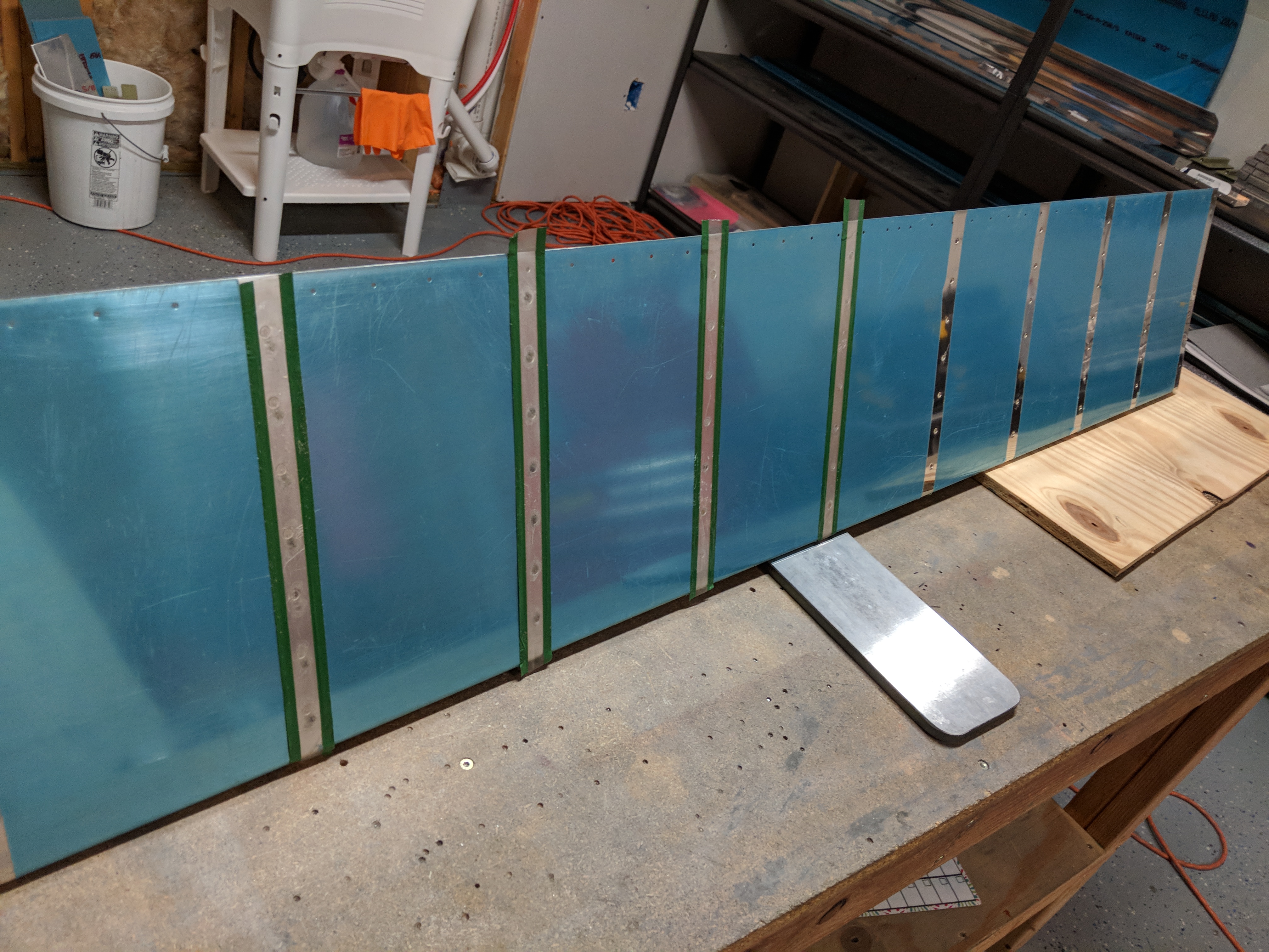
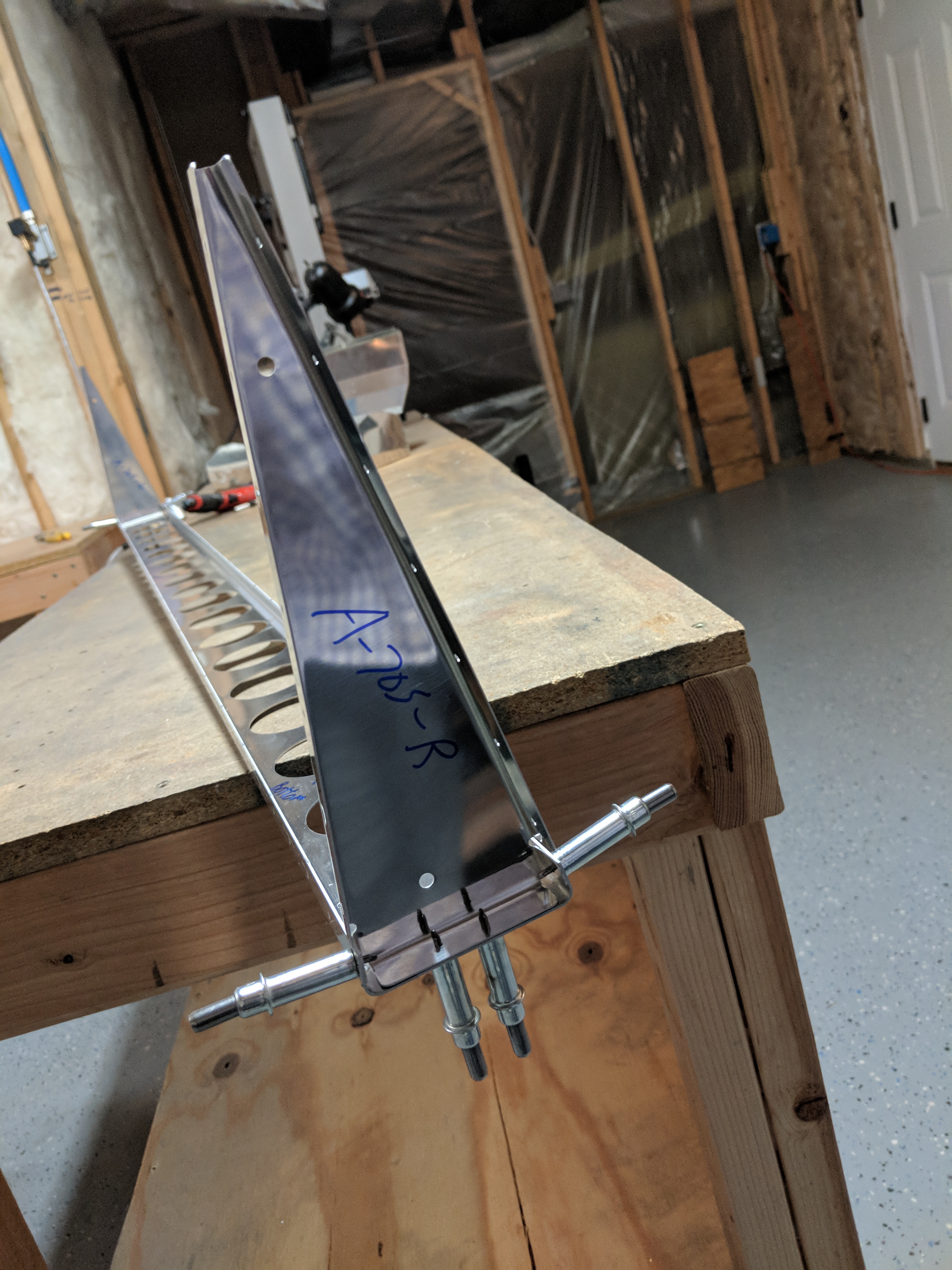
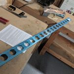
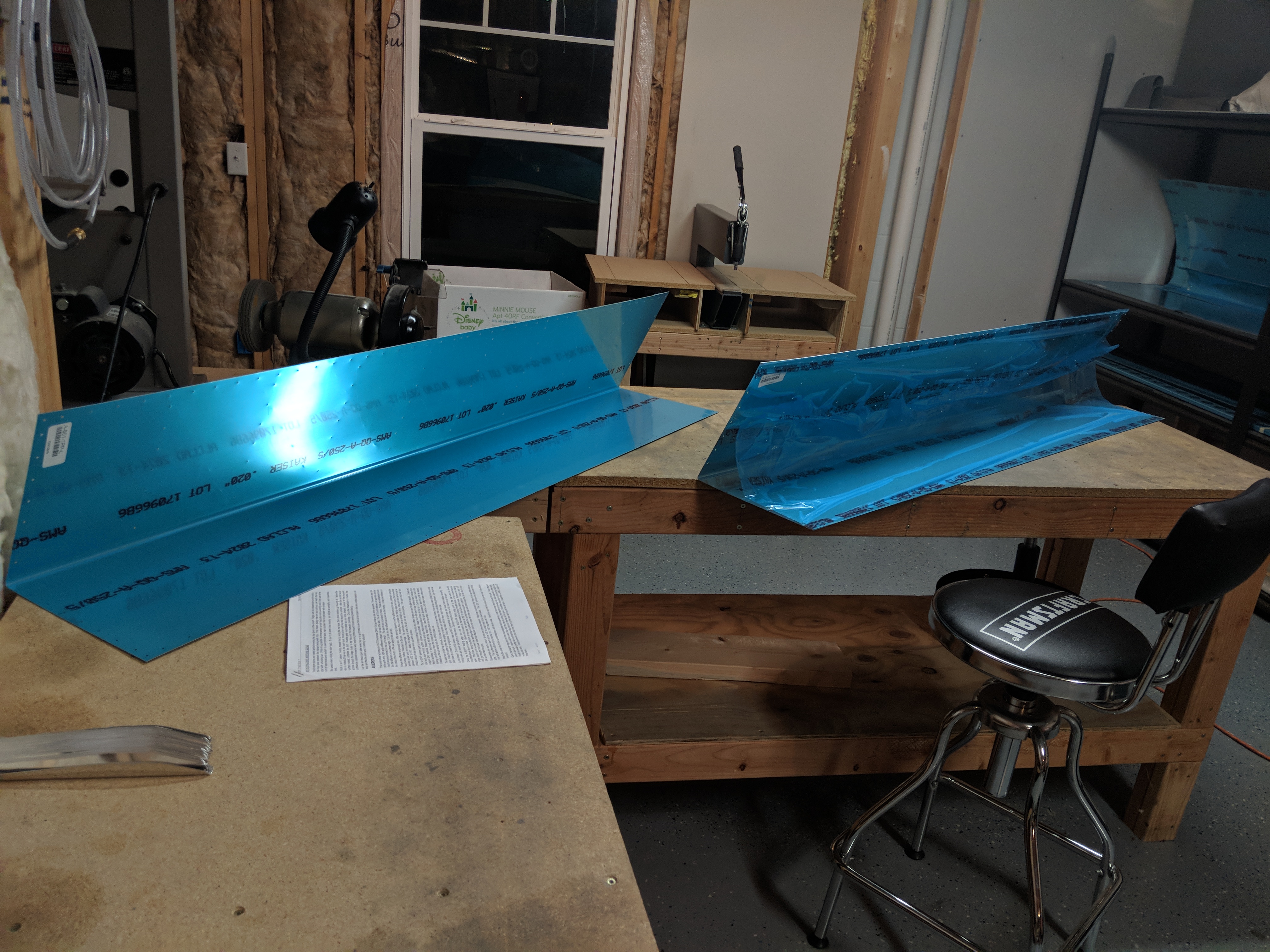
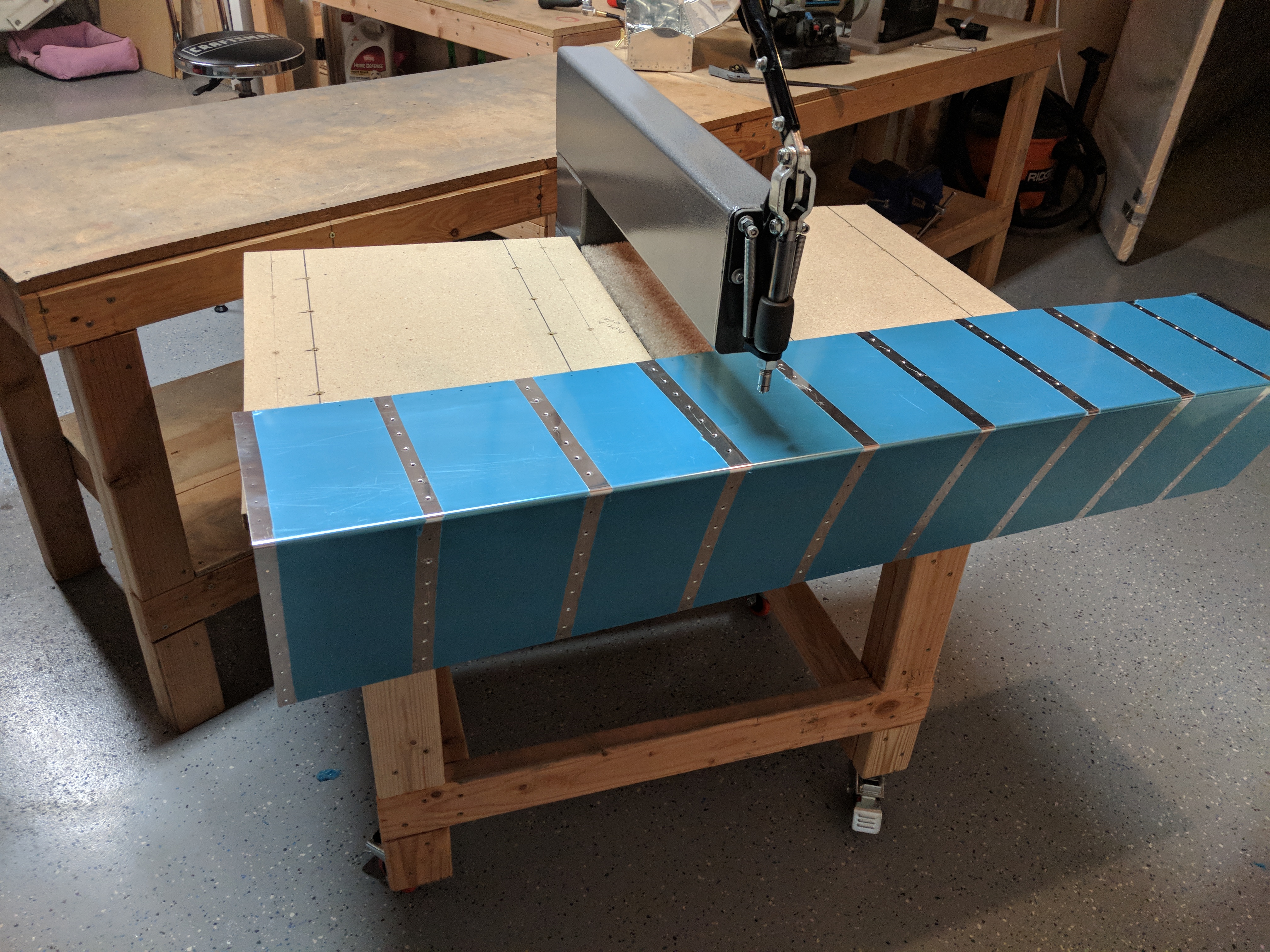
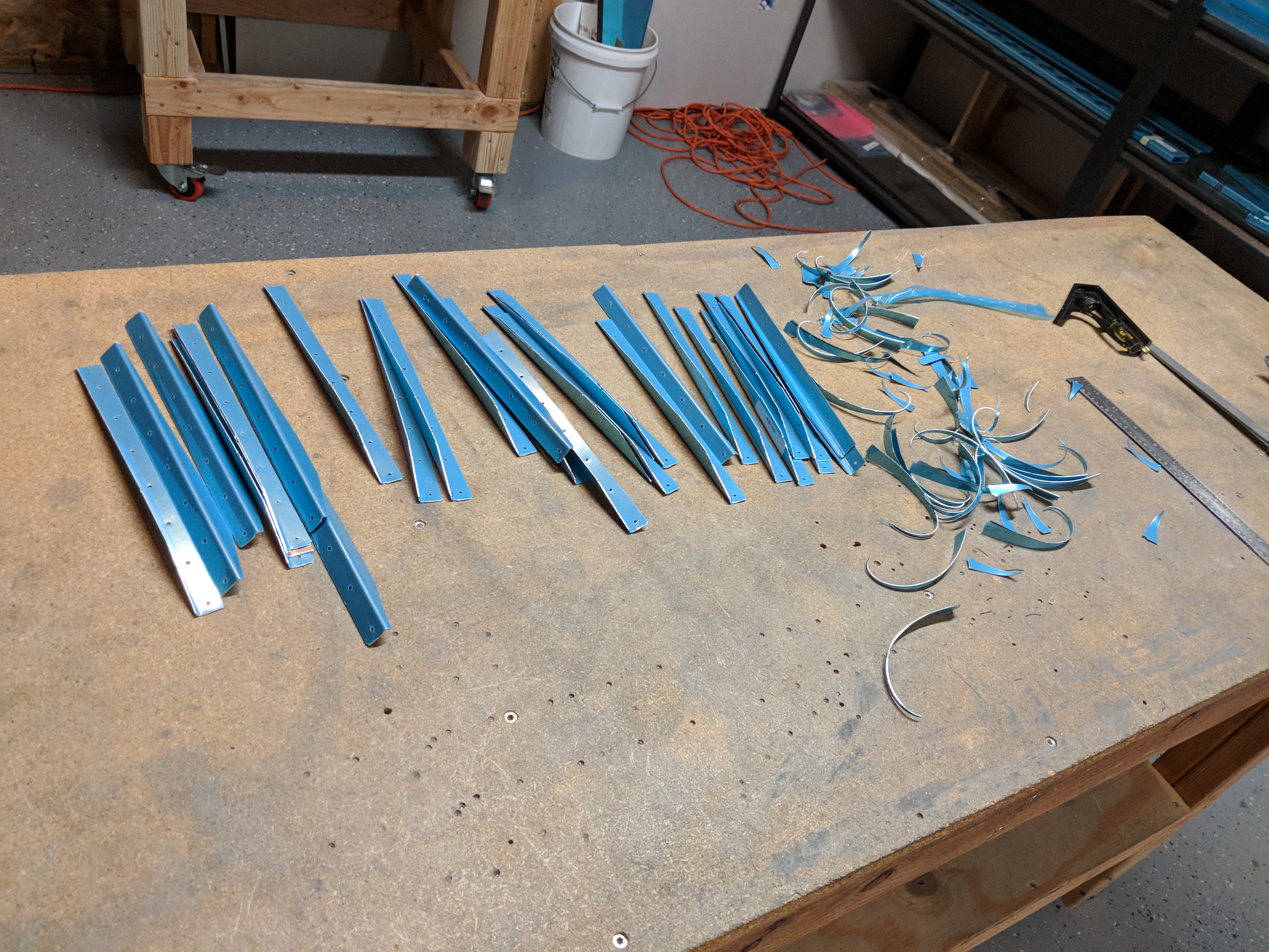
We’re getting close to having a completed aileron! I was able to fully complete the assembly and drilling of the left aileron tonight, and its parts are now ready for deburring, edge finishing, and priming. I will hold off on that until I have the right aileron done and do the all the parts in one big batch. For tonight, I started off by clecoing the A-802PP leading edge skin and the A-801-PP trailing edge skins to the spar and then clecoing the A-705-R/L end ribs into the trailing edge skin.  Once I had that done, I inserted the 1/2″ galavanized water pipe (A-409) into the leading edge skin, and then clecoed the A-704-L/R nose ribs into place to help hold the A-409 counterbalance. Once I had every thing assembled, I double checked for alignment.


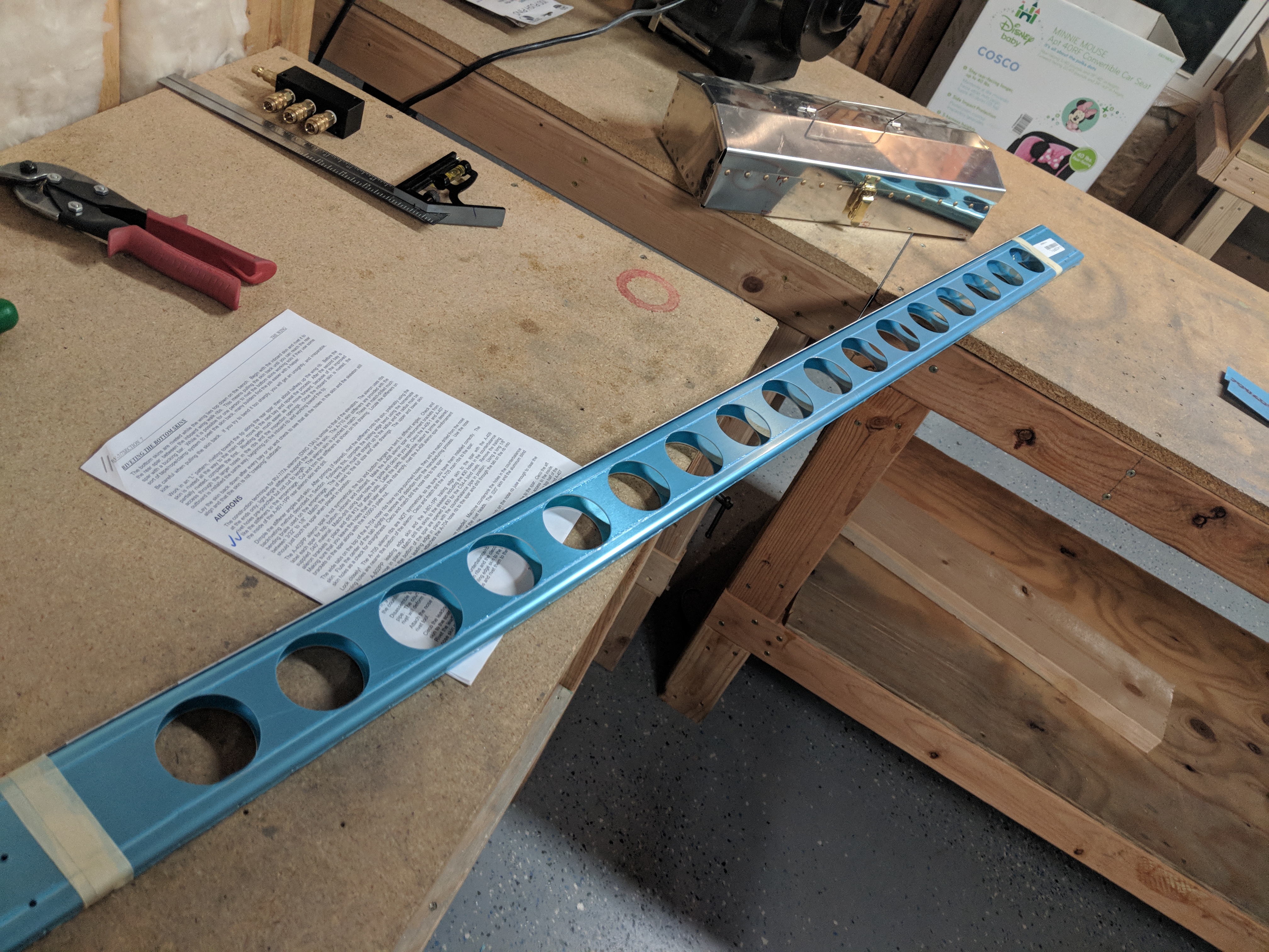
I will admit, I have to admire the utility of using a plain old piece of galvanized 1/2″ water pipe as a counterbalance.  It’s simple, robust, and cheap, all principles that Van’s uses in their “Total Performance” moniker. Thankfully, Van’s ships this pipe in the wing kit, and its precut to length!  Once I had made sure everything was still in alignment, I went ahead and match drilled everything to their respective hole sizes.  The normal process is I cleco every other hole, and then match drill the empty holes to their correct size, then move the clecos over by one hole and drill the rest of the holes. I like to use a lot of clecos on the ends to help hold everything secure, so I have to make sure I remove them, drill and then replace them afterwards.  I am also going to use a edge roller / former to break the edge of the leading edge skins before I dimple.  This will give the skins a nice flat joint when I rivet them.

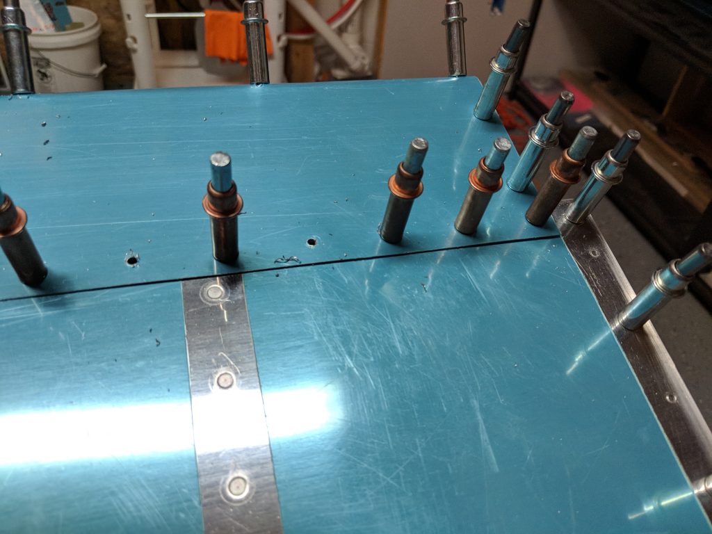
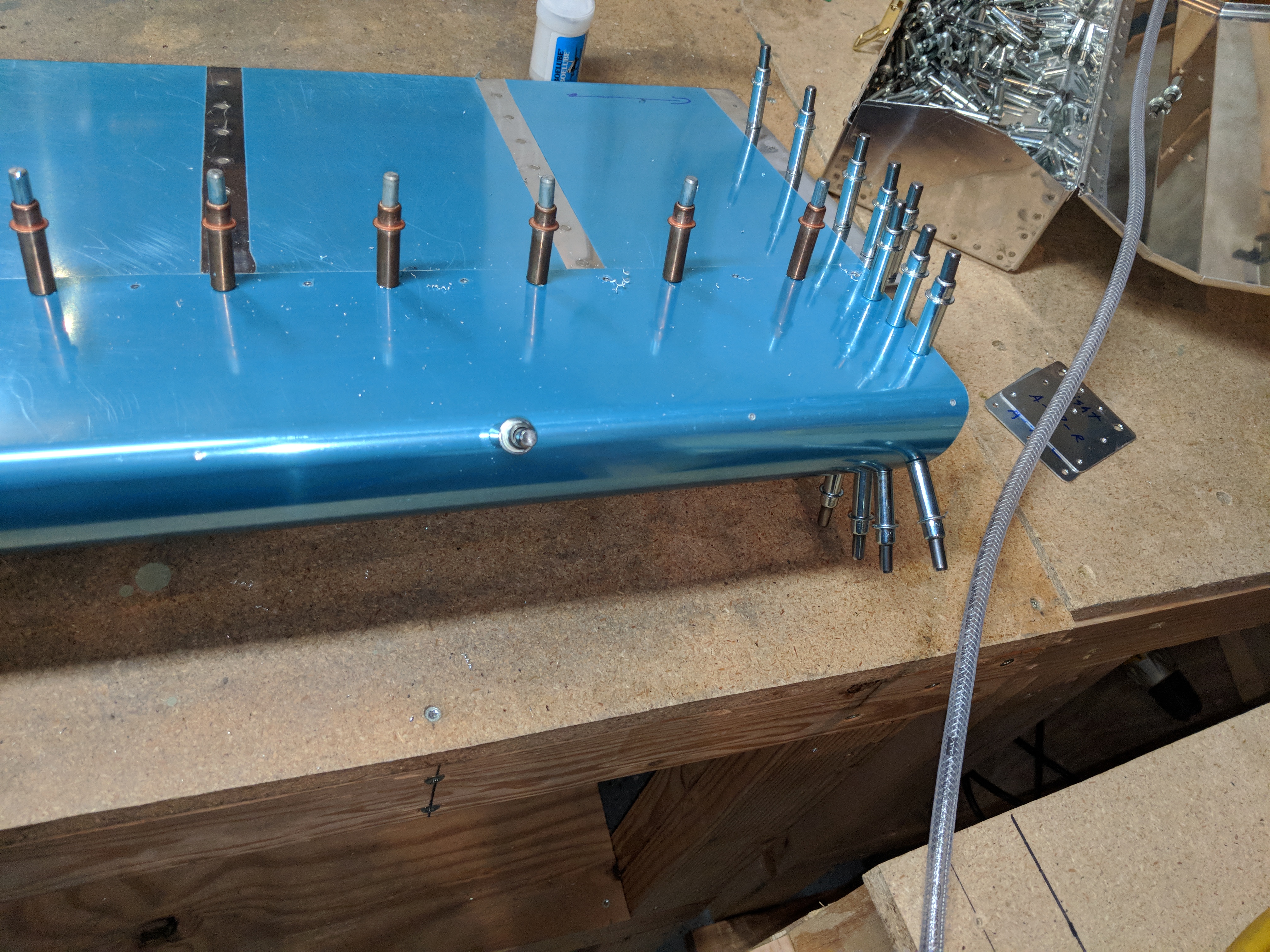
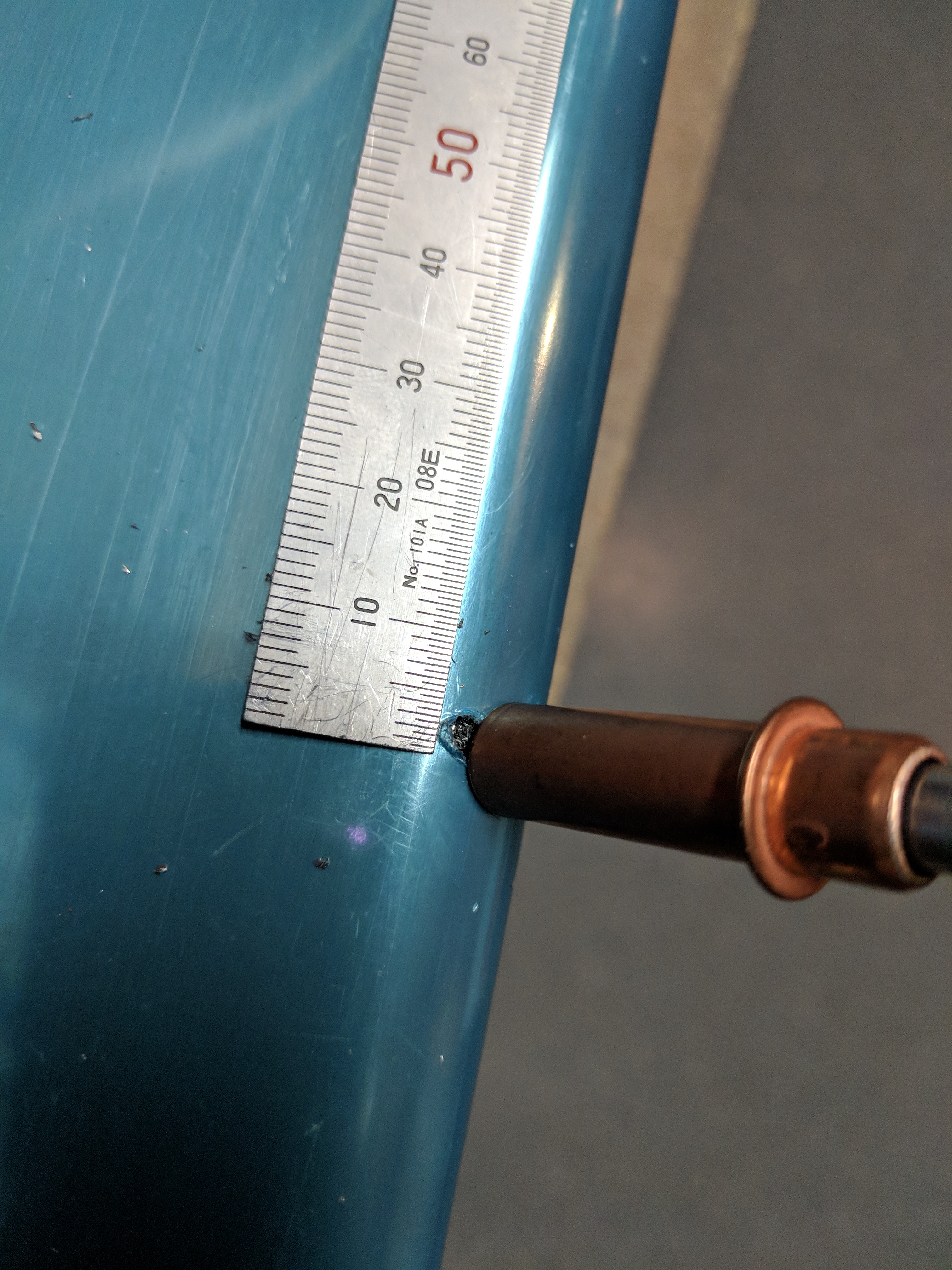
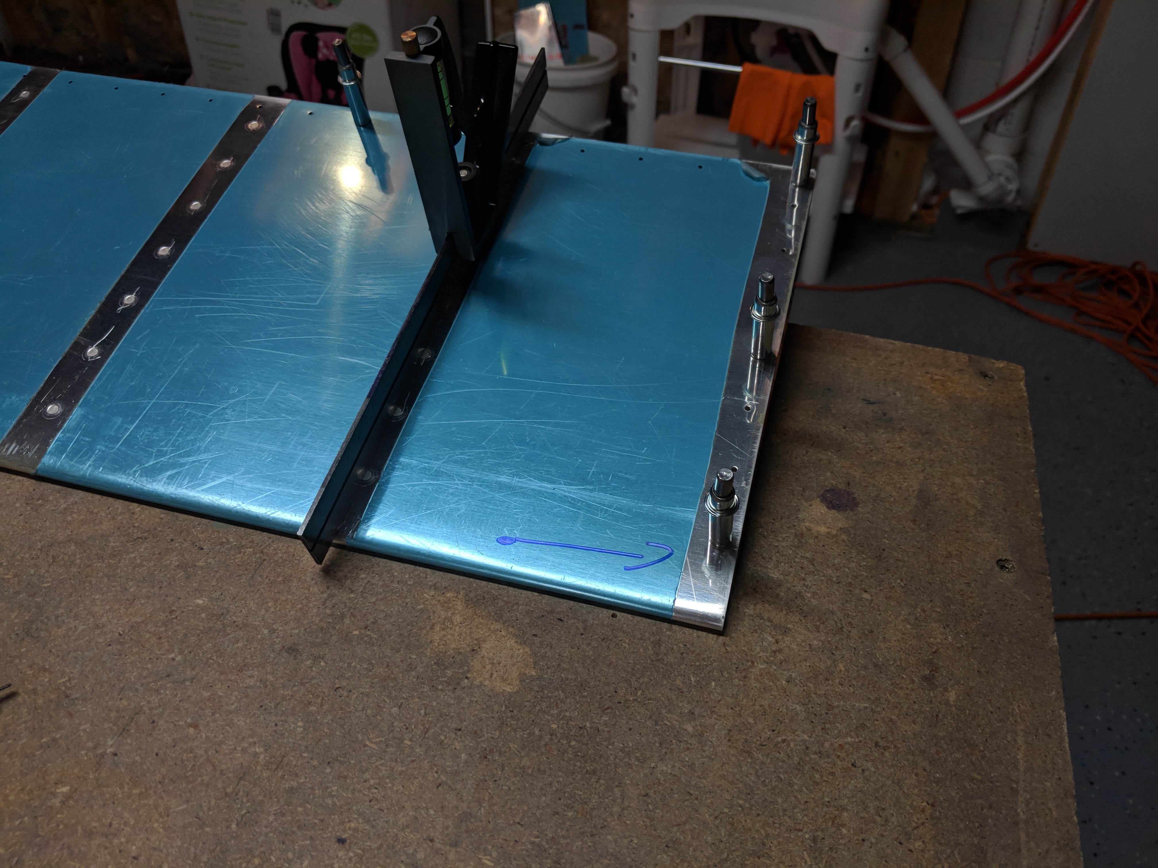
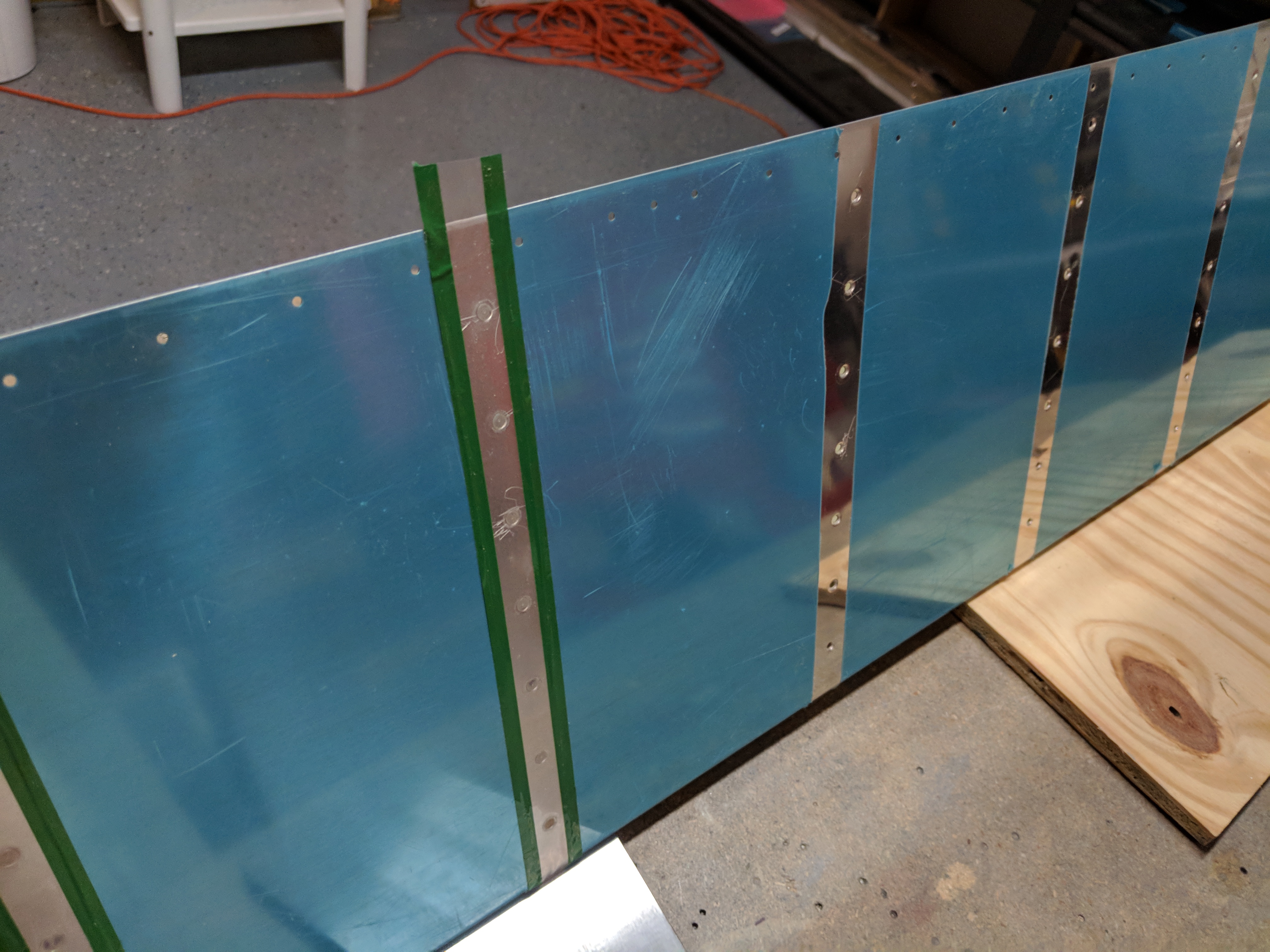
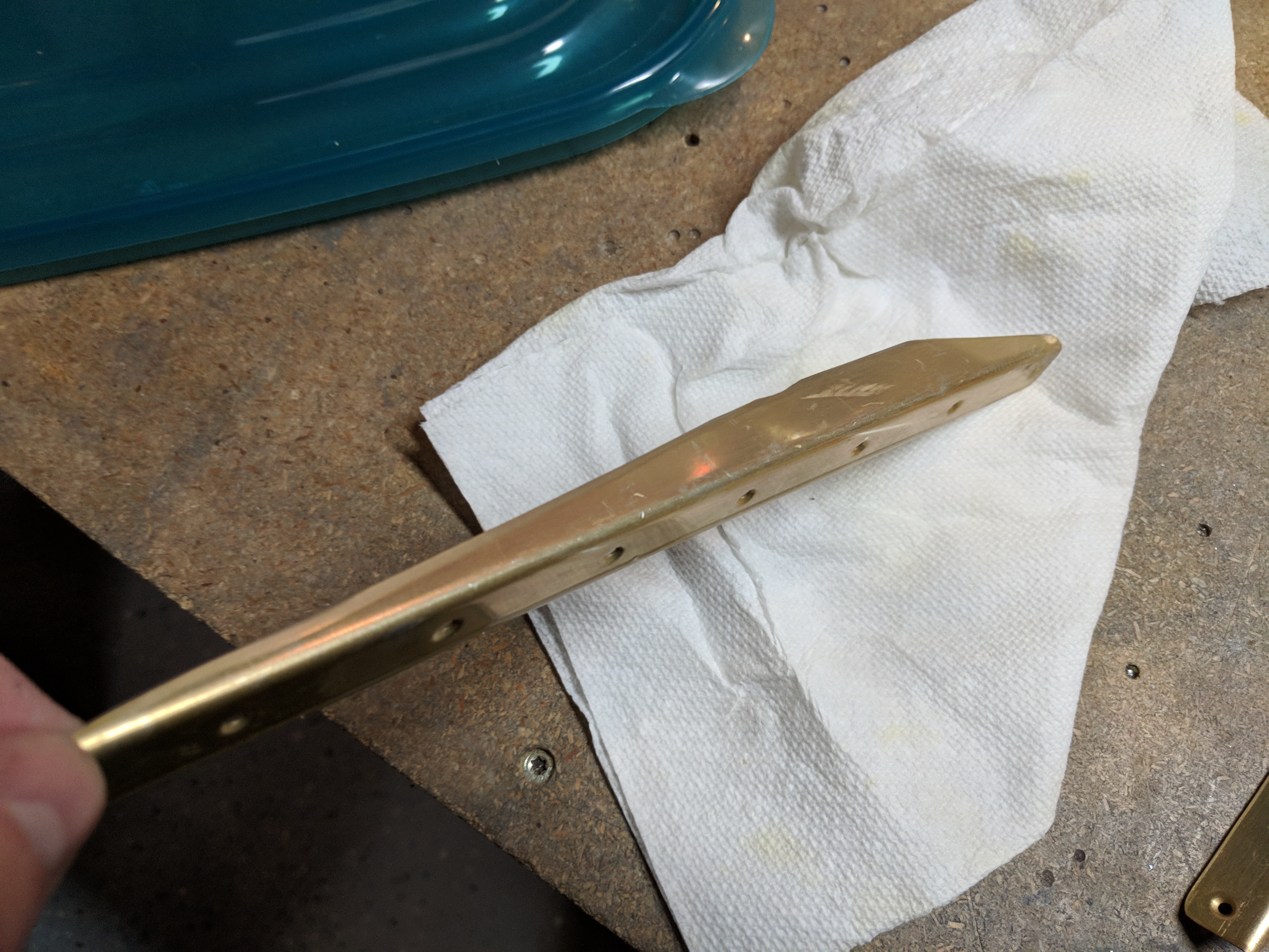
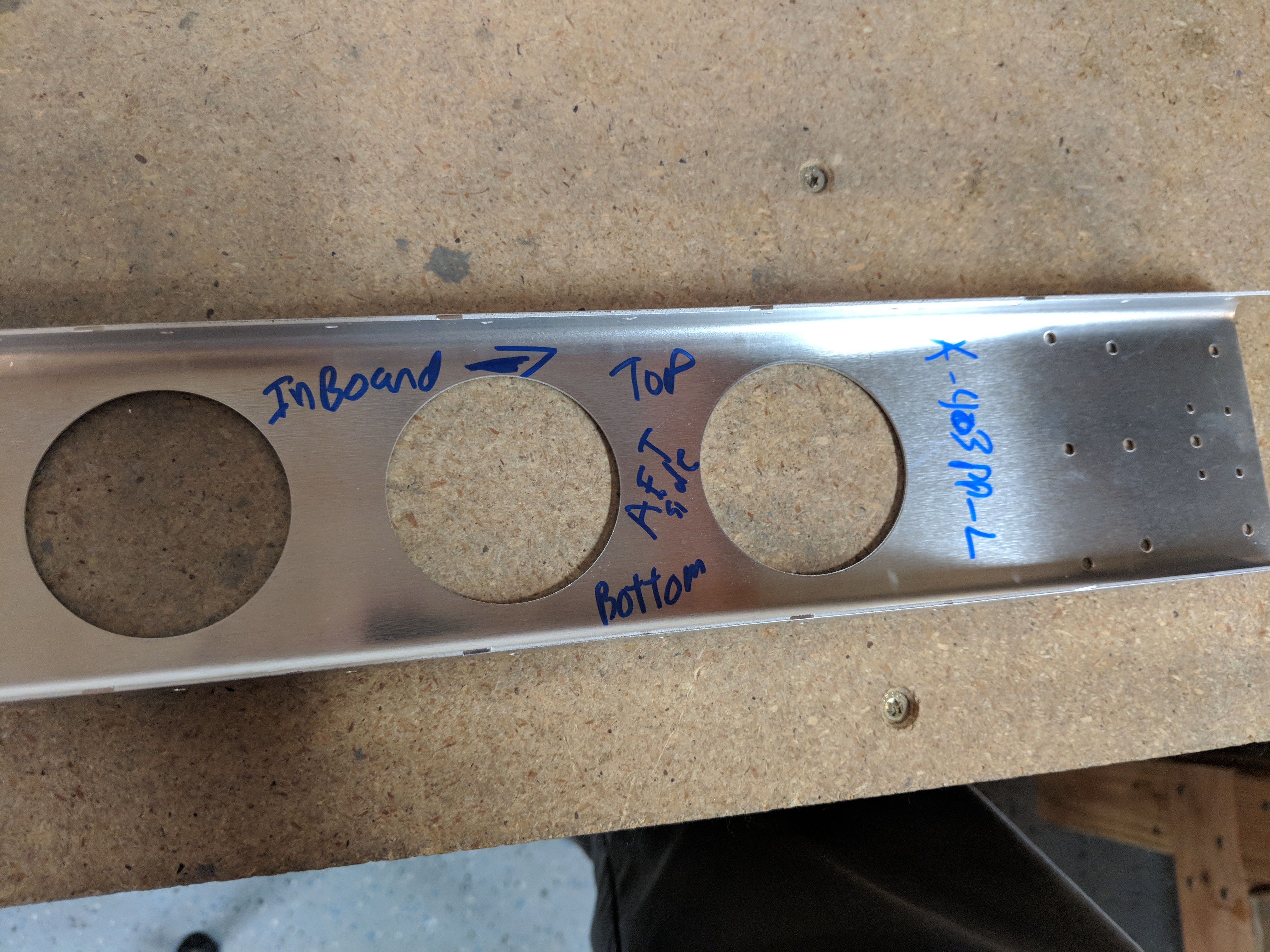
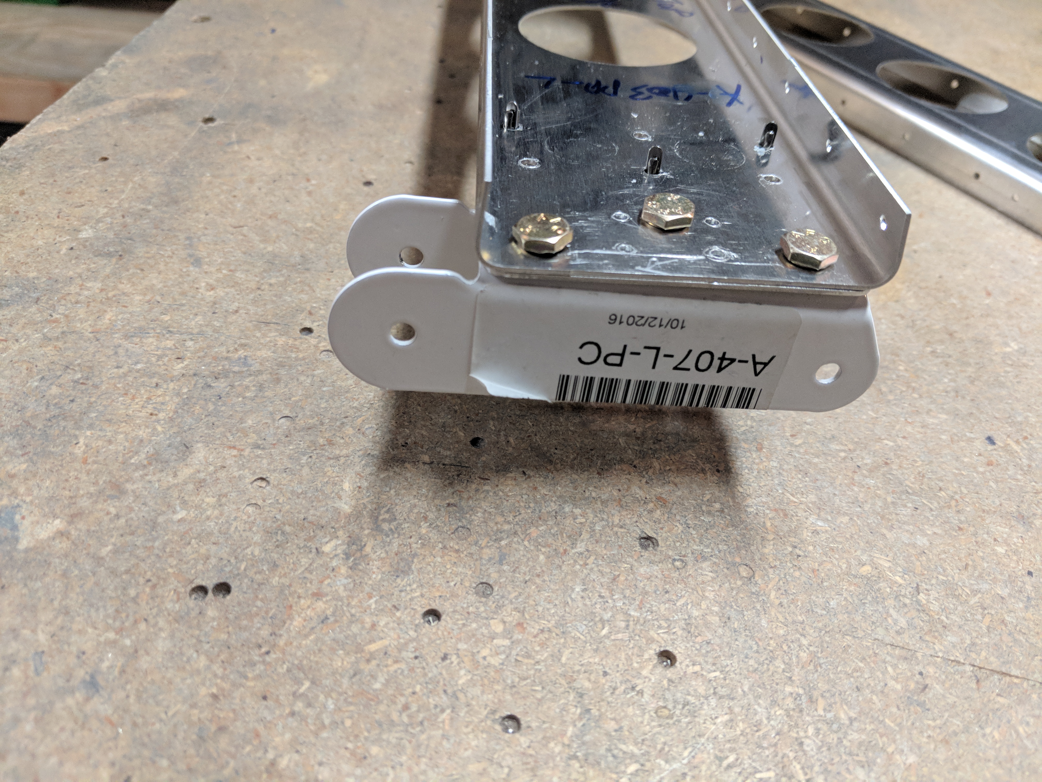
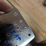
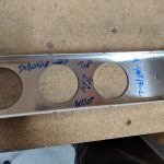
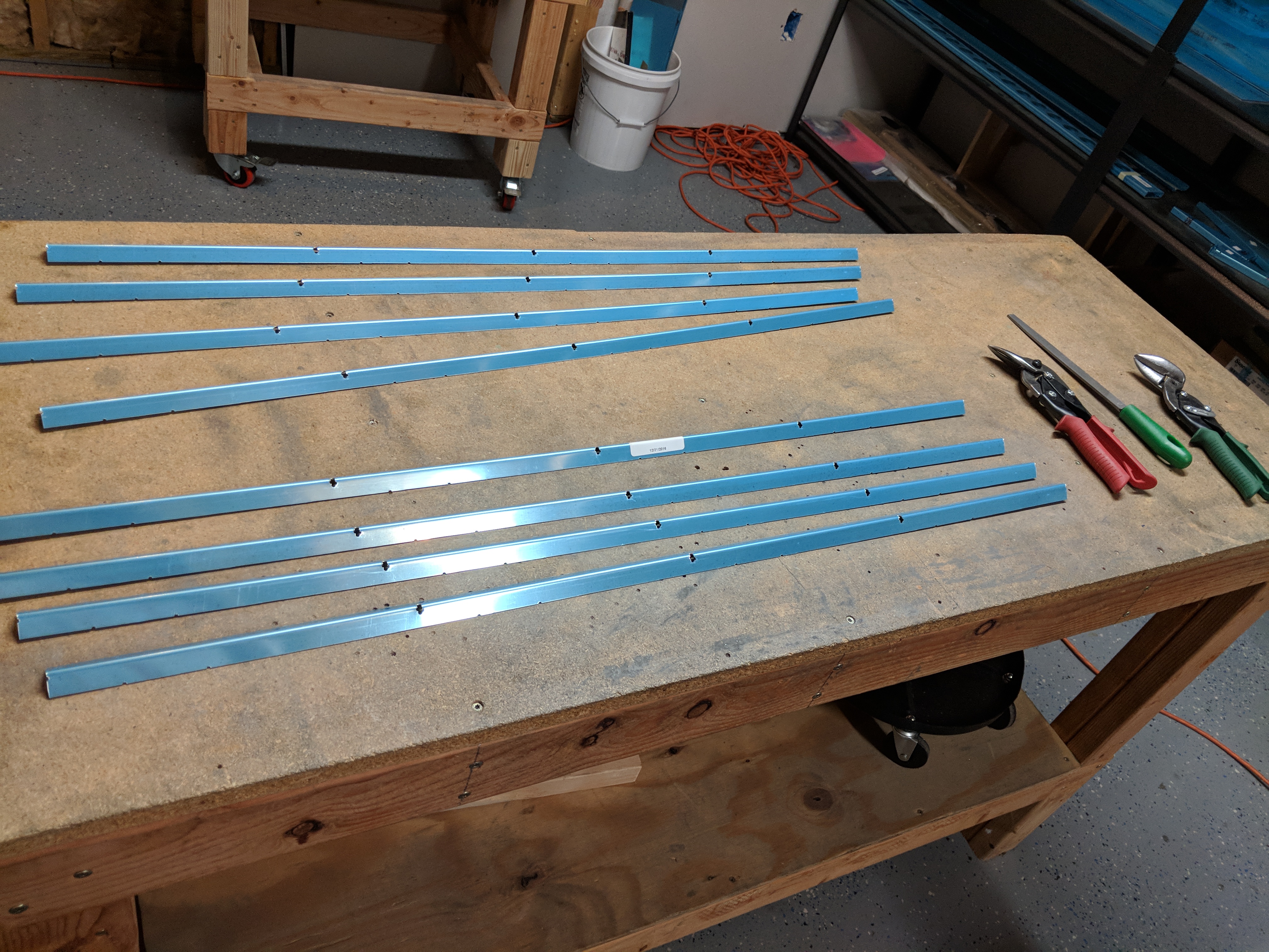
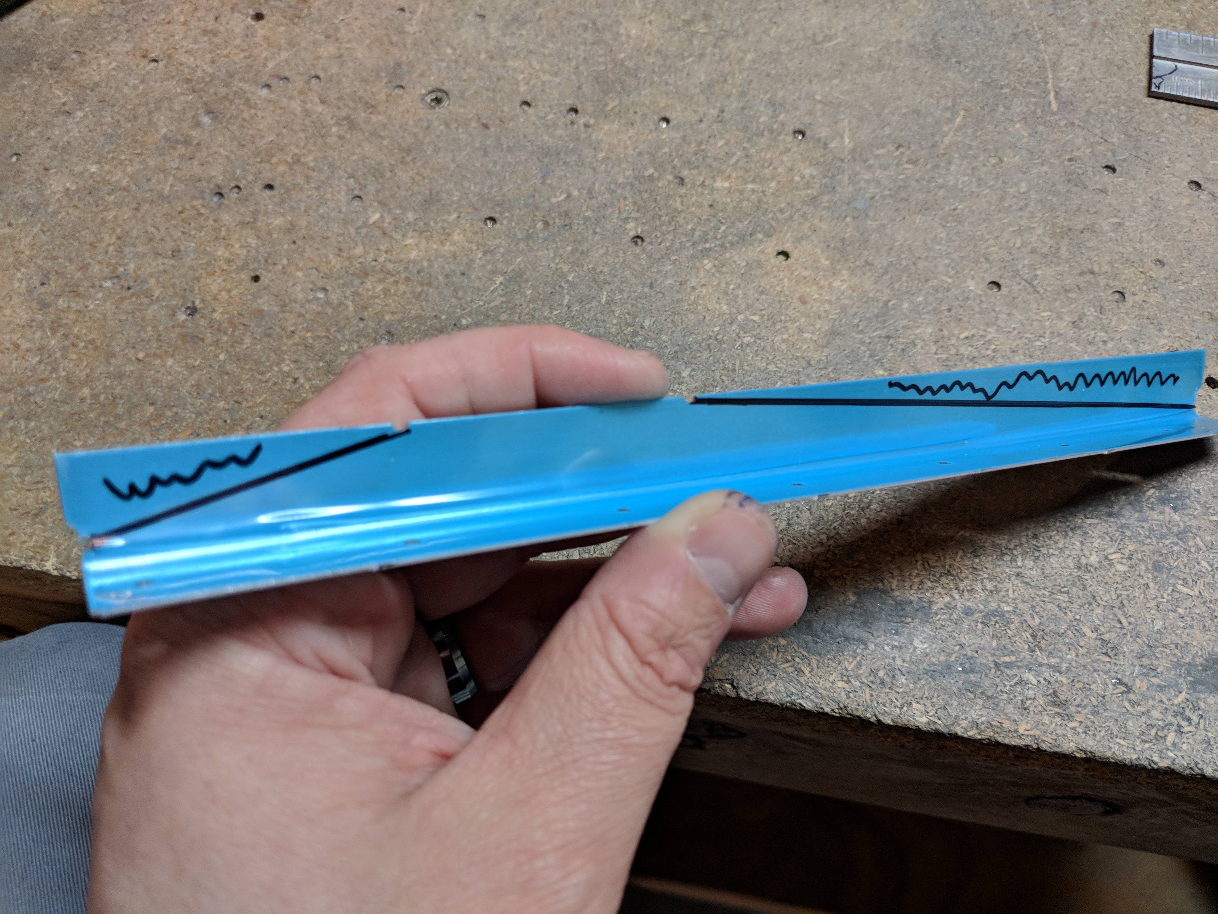
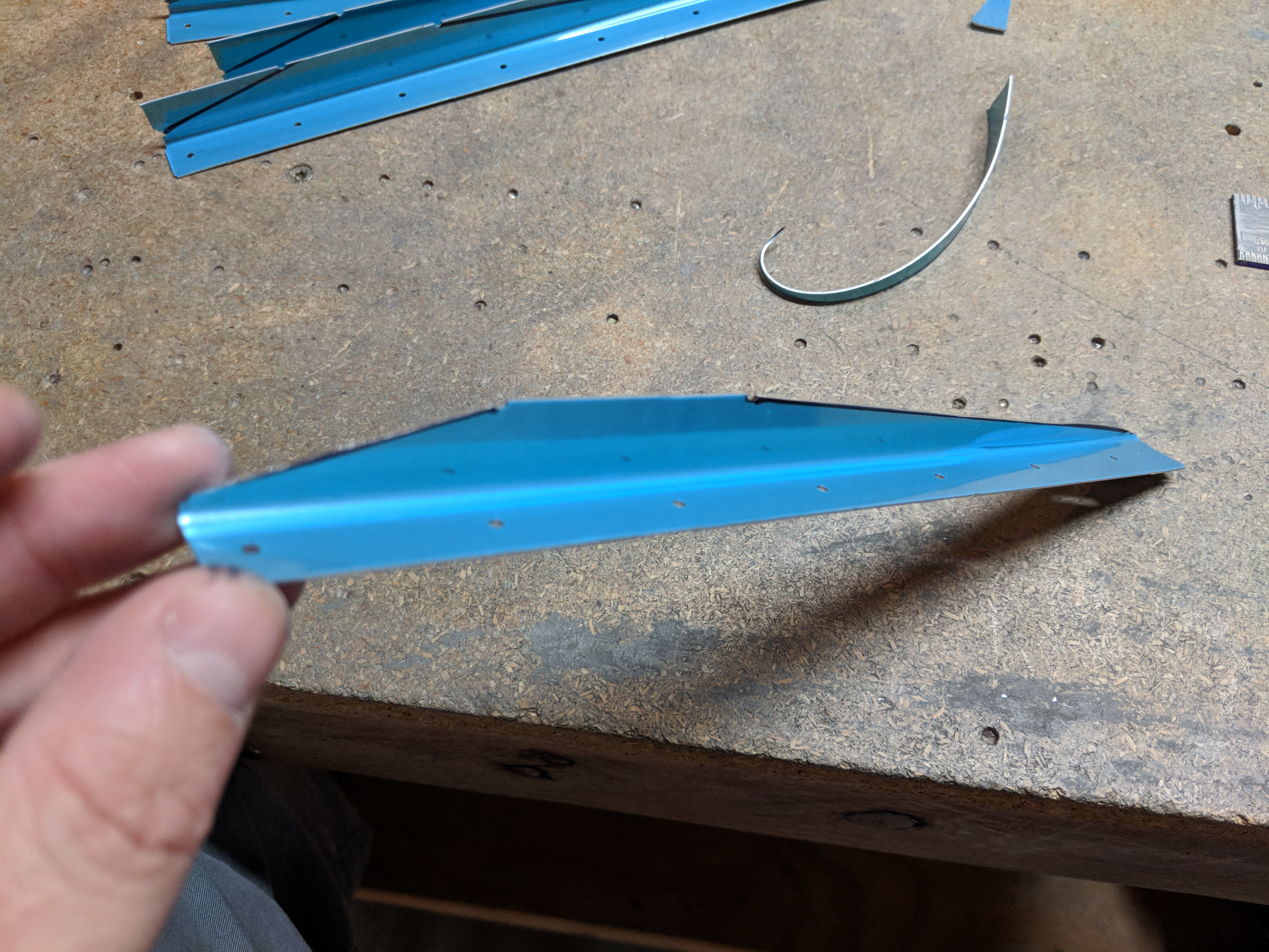
Along the bottom of the aileron, where the leading edge skin and trailing edge skins overlap one another on top of the spar, I drilled the holes for a #30, as called for in the plans to fir the CS4-4 blind rivet.  Next up was to drill the holes into the A-409 counterbalance / water pipe using the pre-punched holes in the skin as a guide.  HERE’S where I think I may have messed up.  Take a look at the photo below:

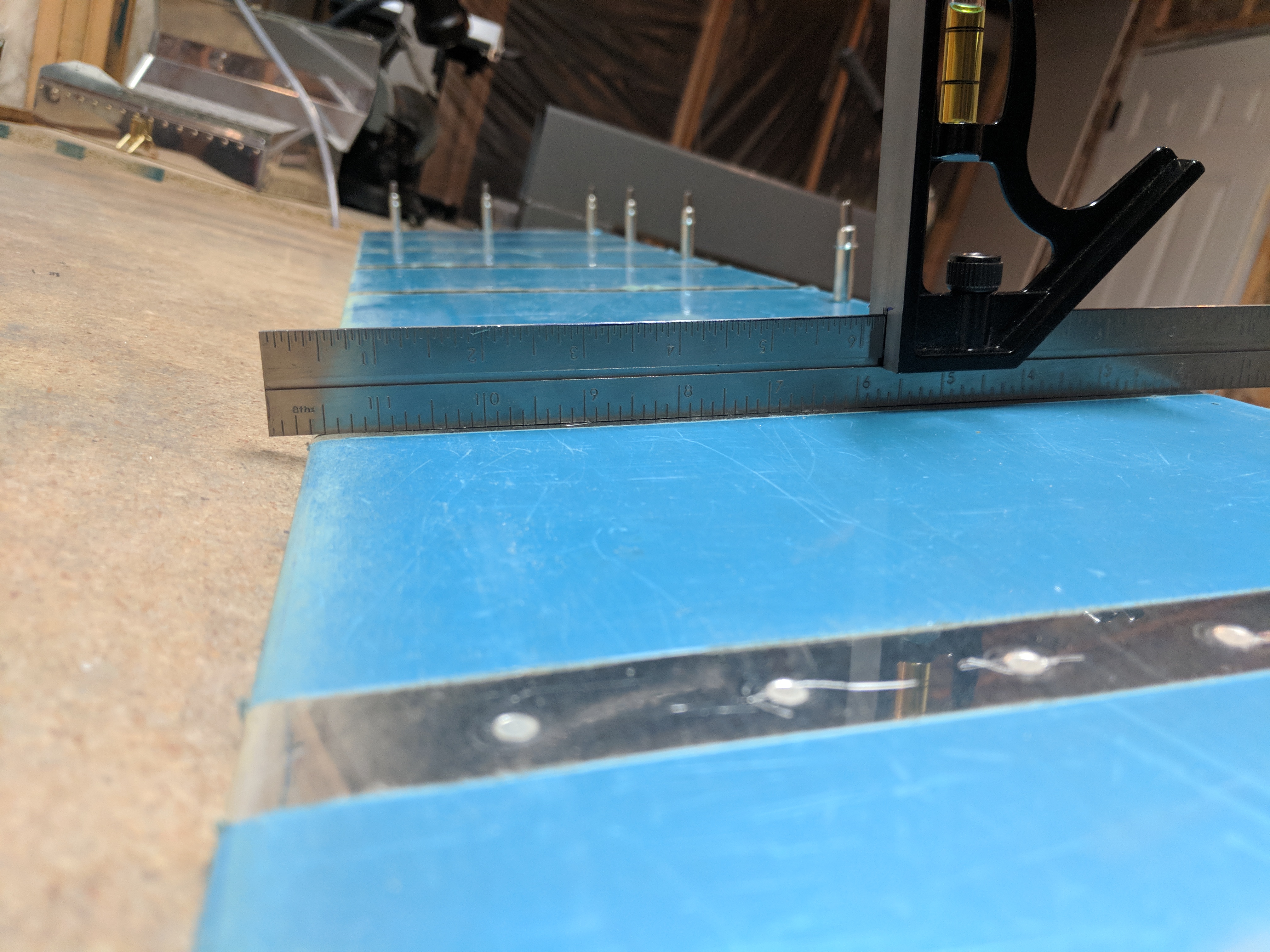
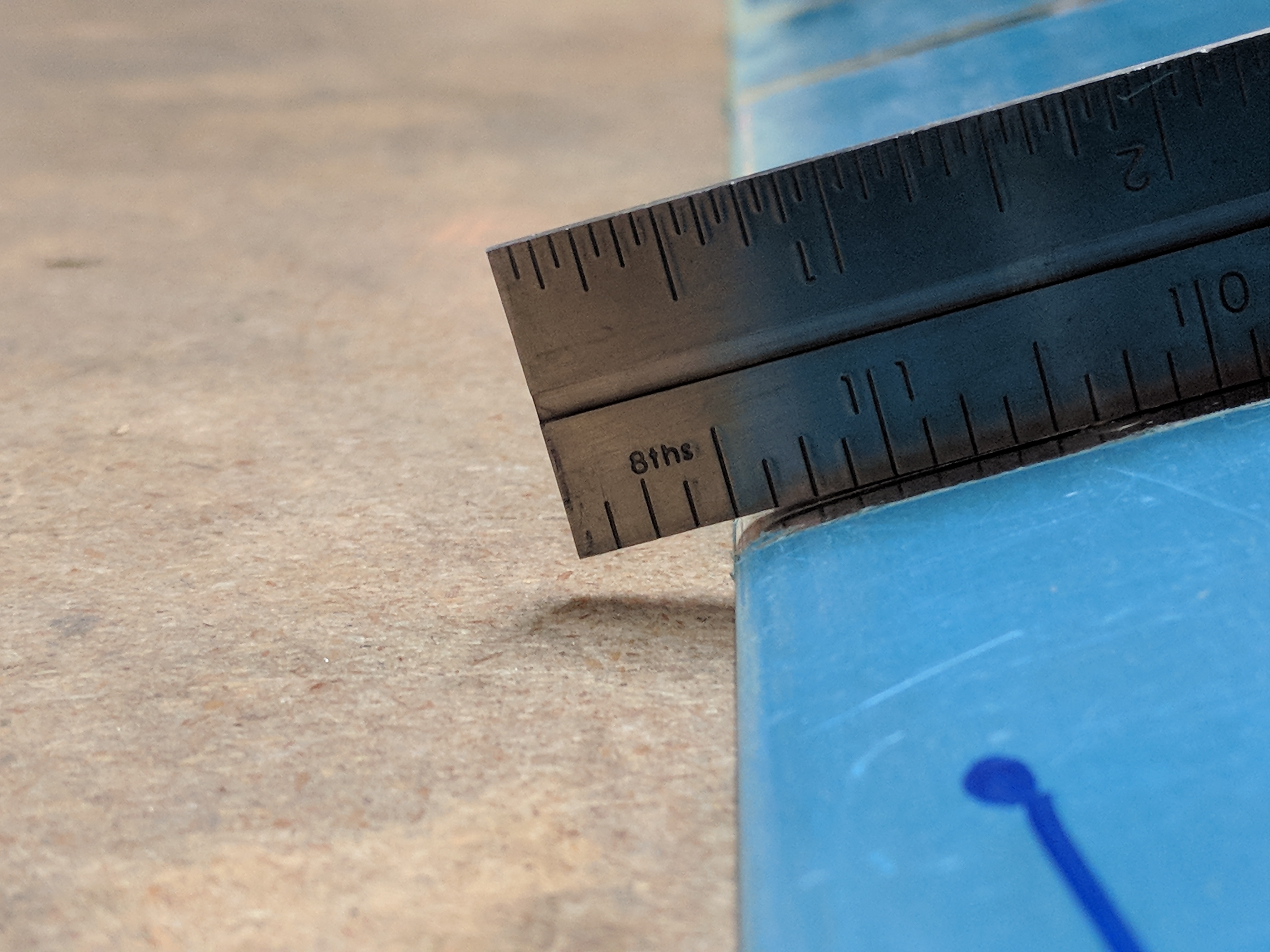
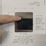
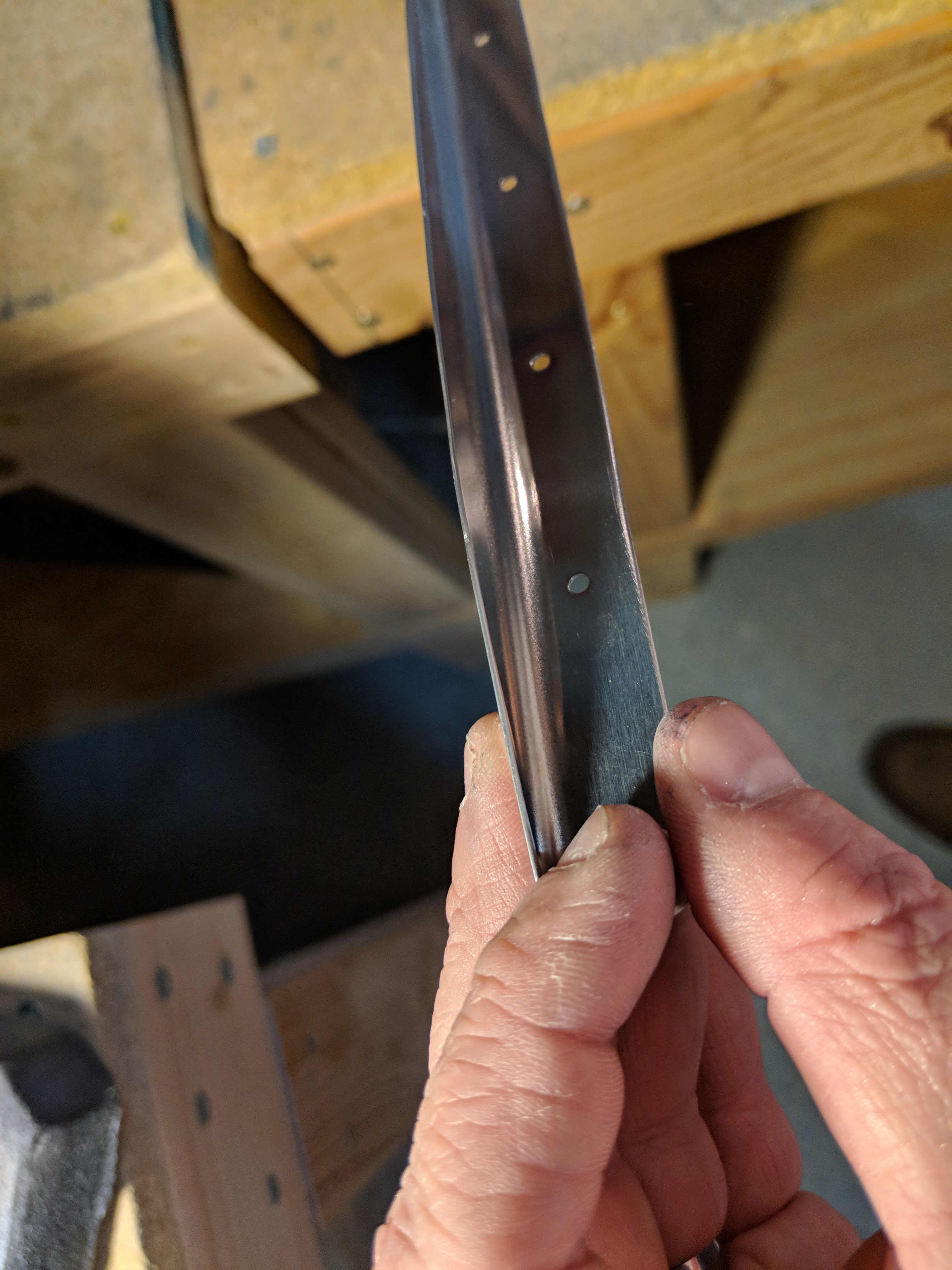
Do you see that ugly oblong hole in the skin?  This is the first time I drilled this counterbalance, and somehow my drill walked and chewed away at my skin before it made a pilot hole in the counterbalance beneath. It’s zoomed in in that photo, so it looks bad, heres a ruler for scale:


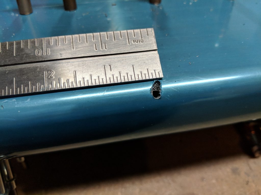
However, with this new found knowledge, I decided that the best course of action was to step my drill down to a #40 first, drill the holes and then move up to a #30 and enlarge the hole to its final size.  Which worked out wonderfully on all the rest of the holes in the counterbalance. BUT, I am concerned about this.  I’m going to give Van’s a call in the morning and send them the photos to get their opinion on it.  Worst case scenario is I have to buy a new leading edge skin and A-409 water pipe, best case is that they tell me to use a bigger hole and rivet (which would be super easy to do).  I’ll update this post when I find something out.

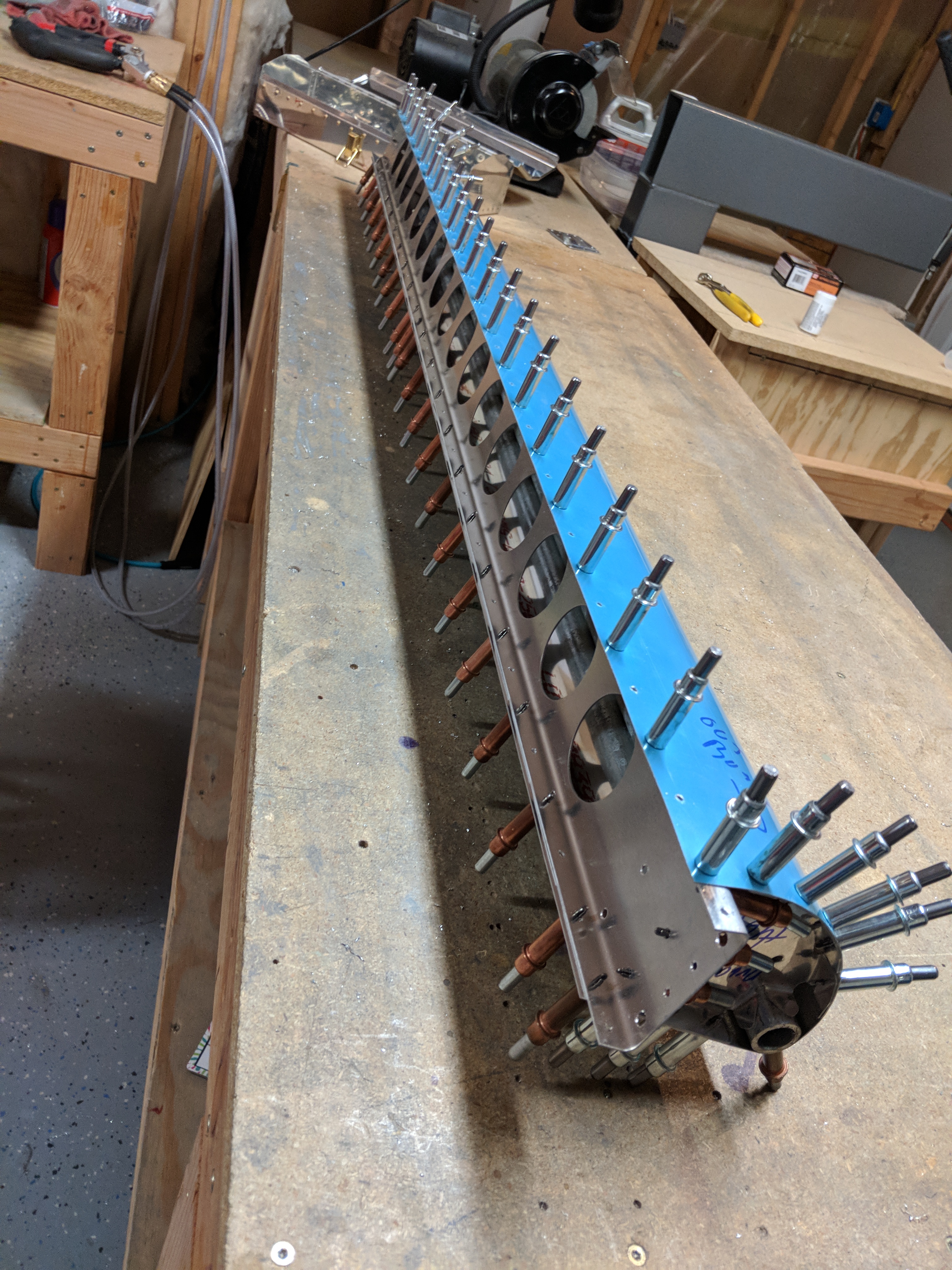
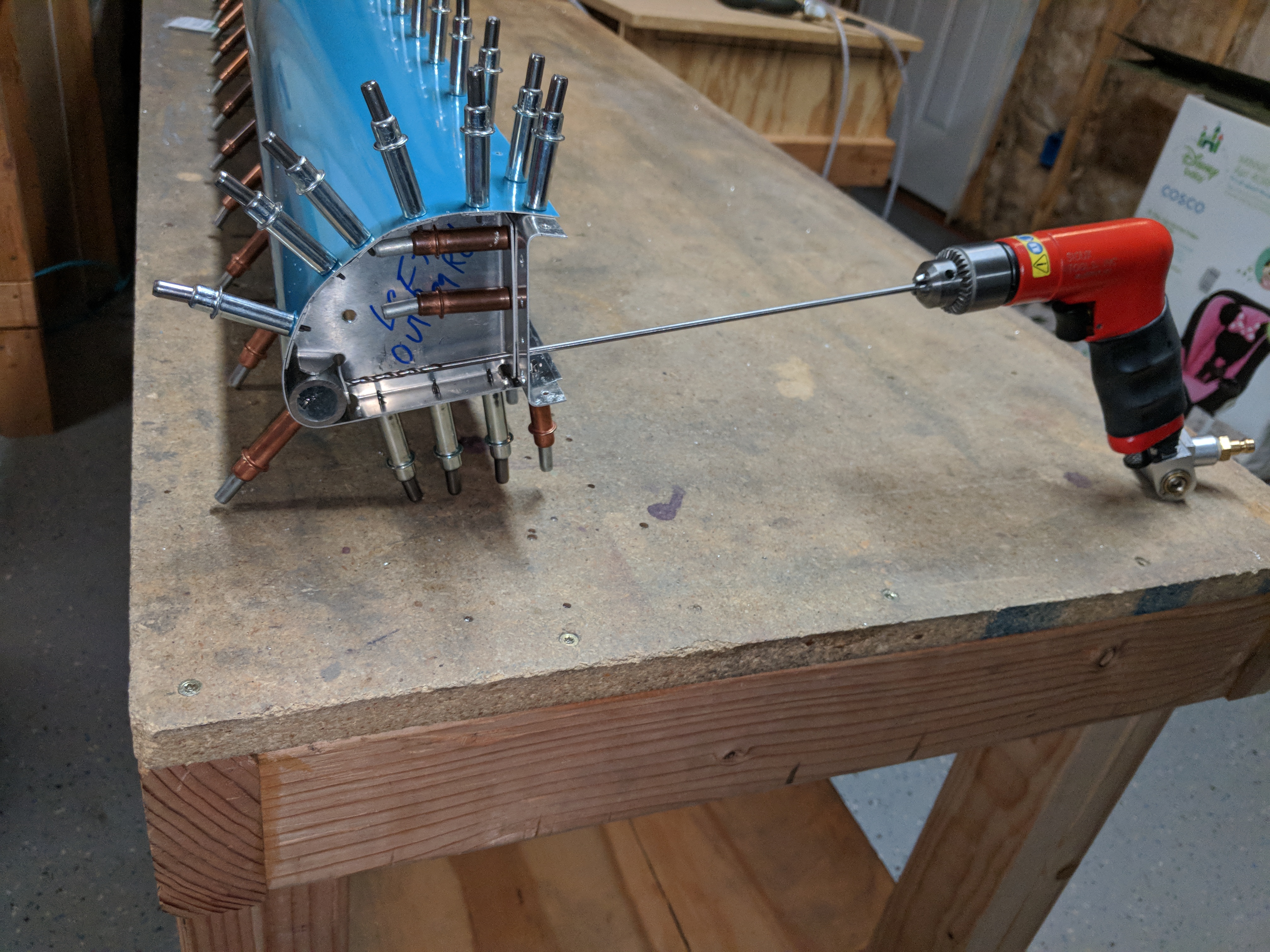
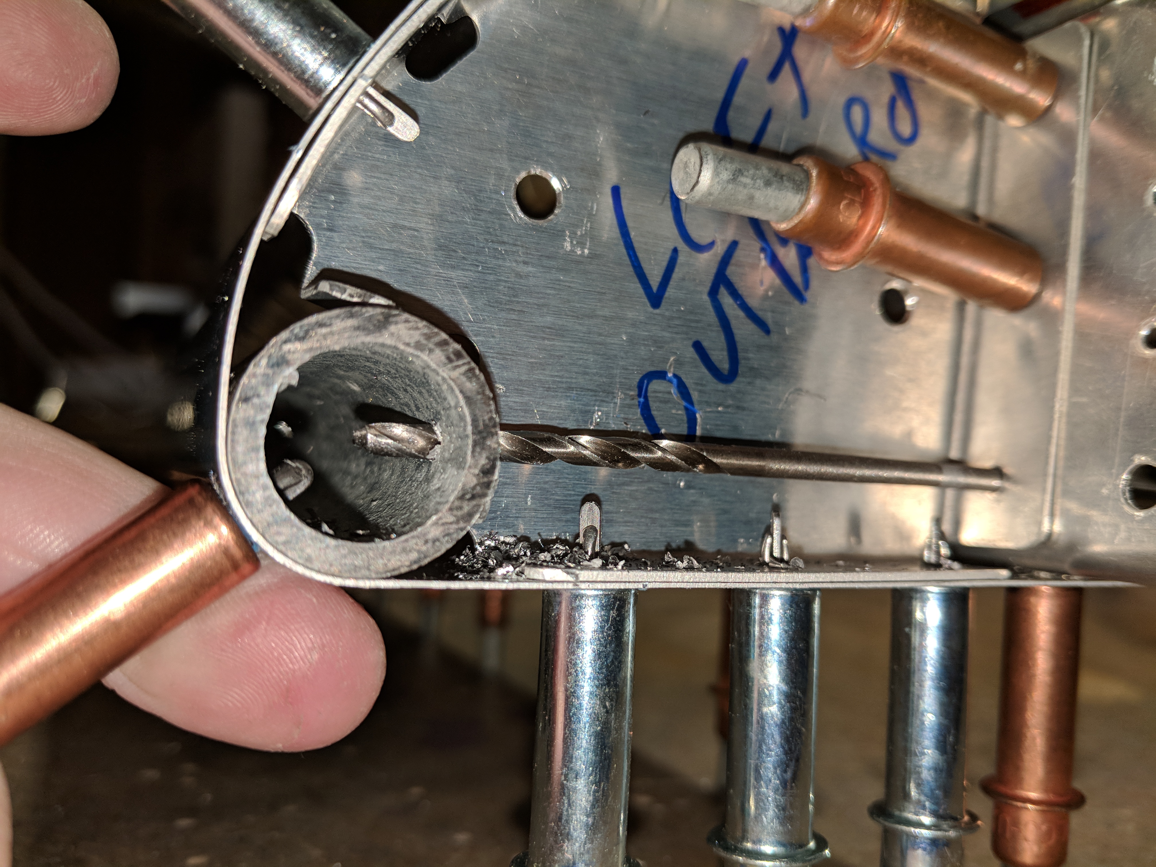
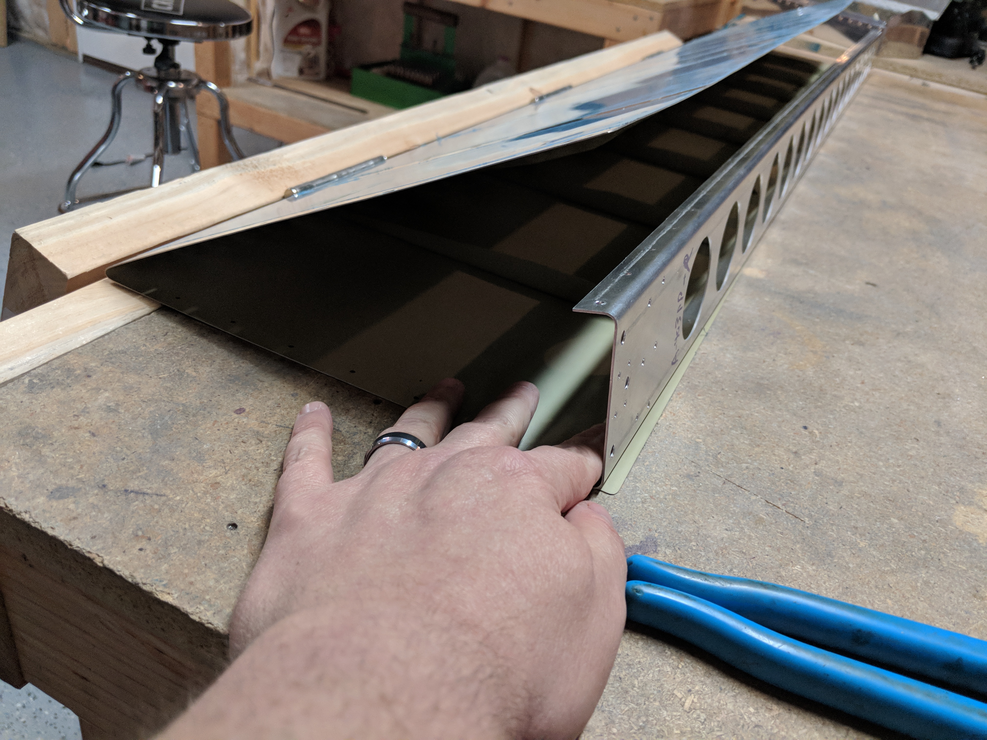
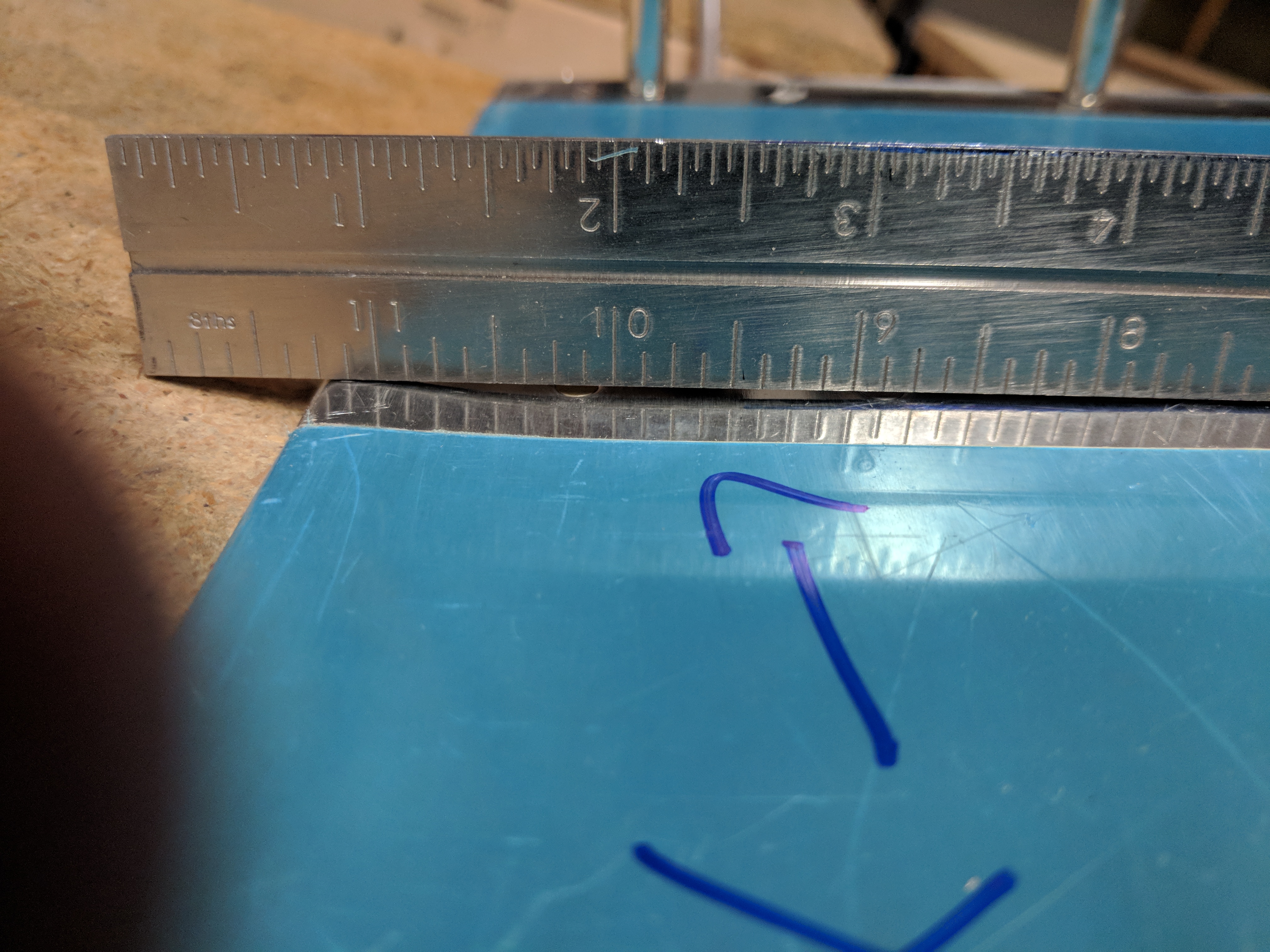
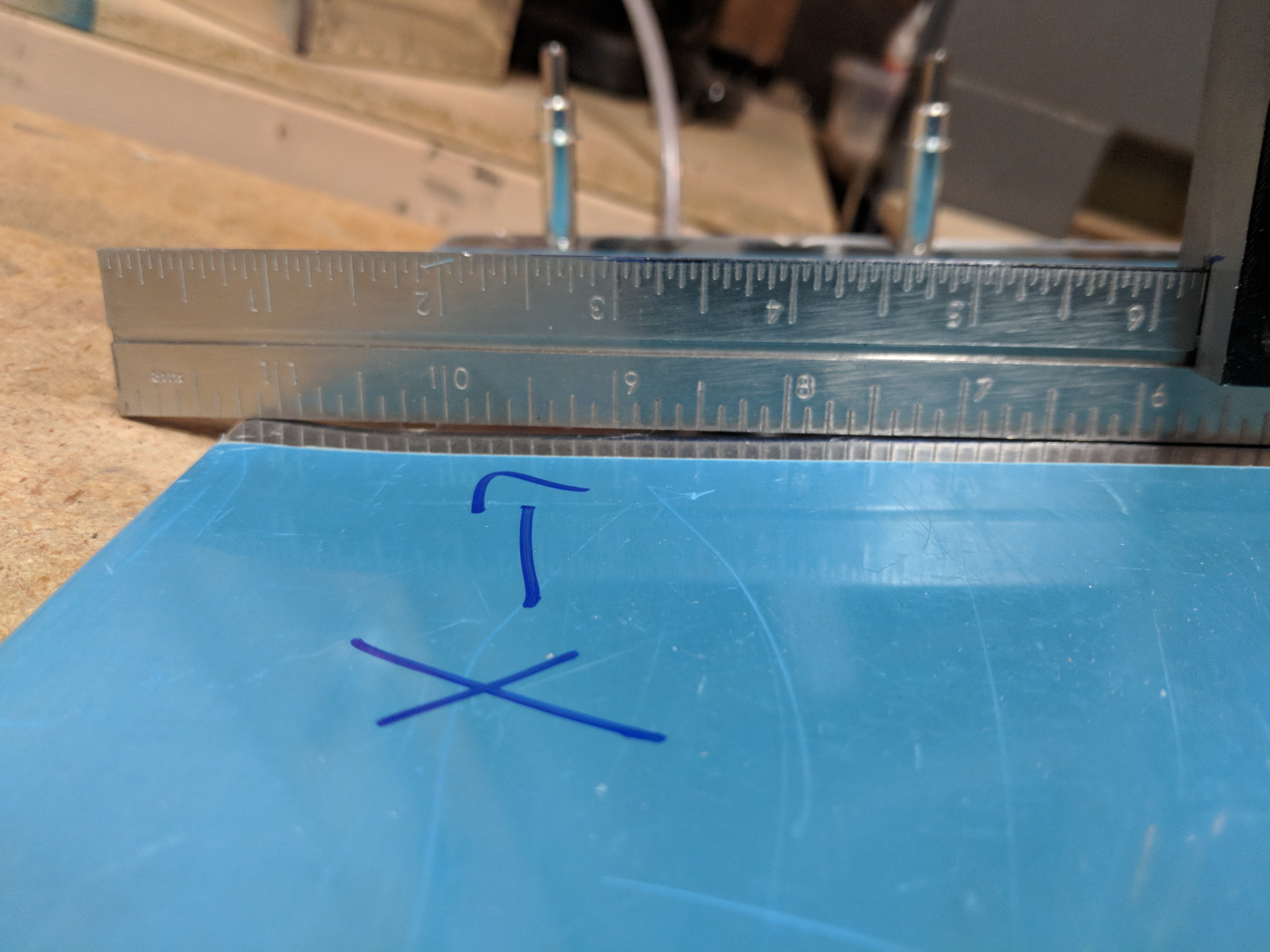
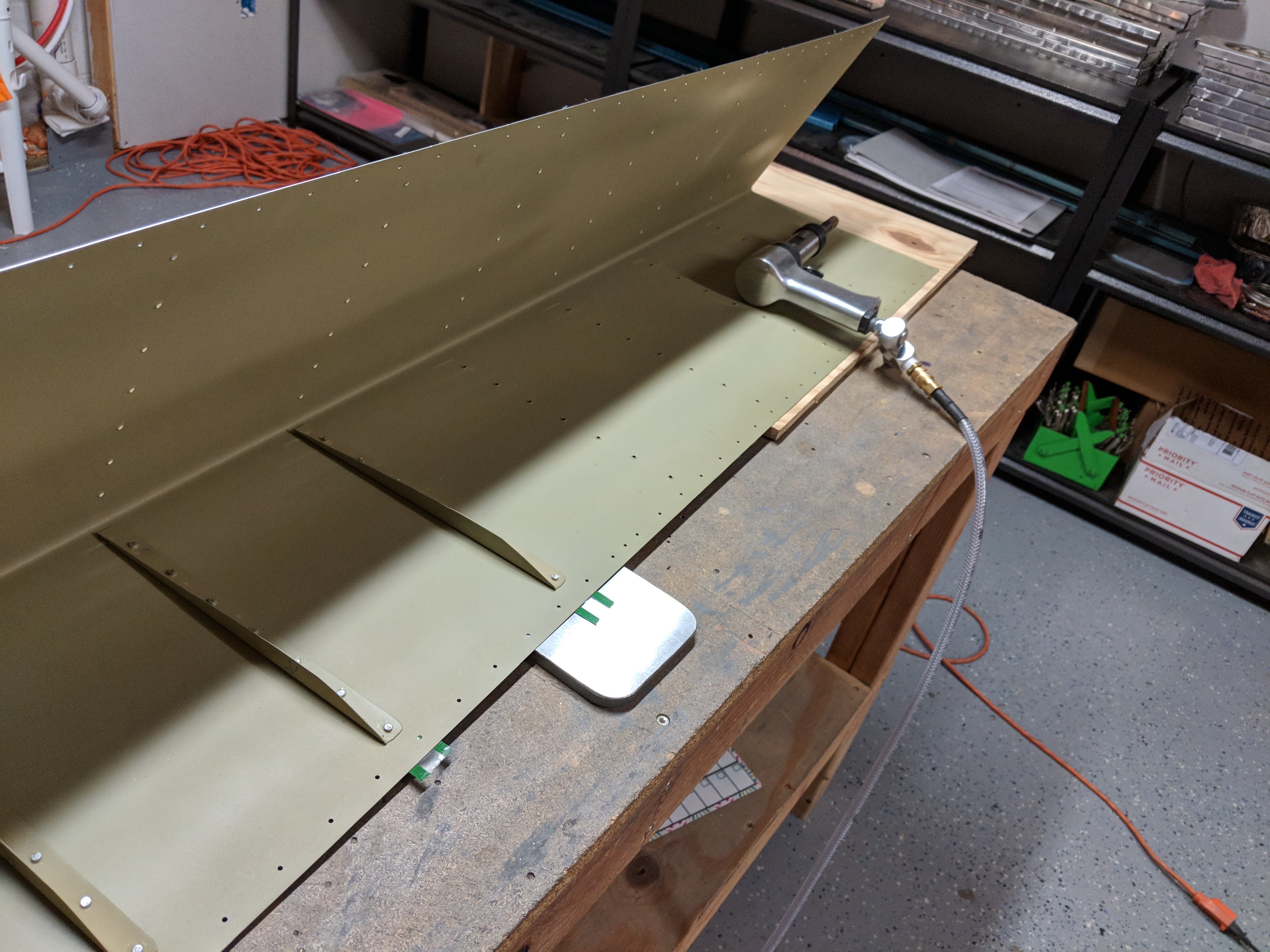
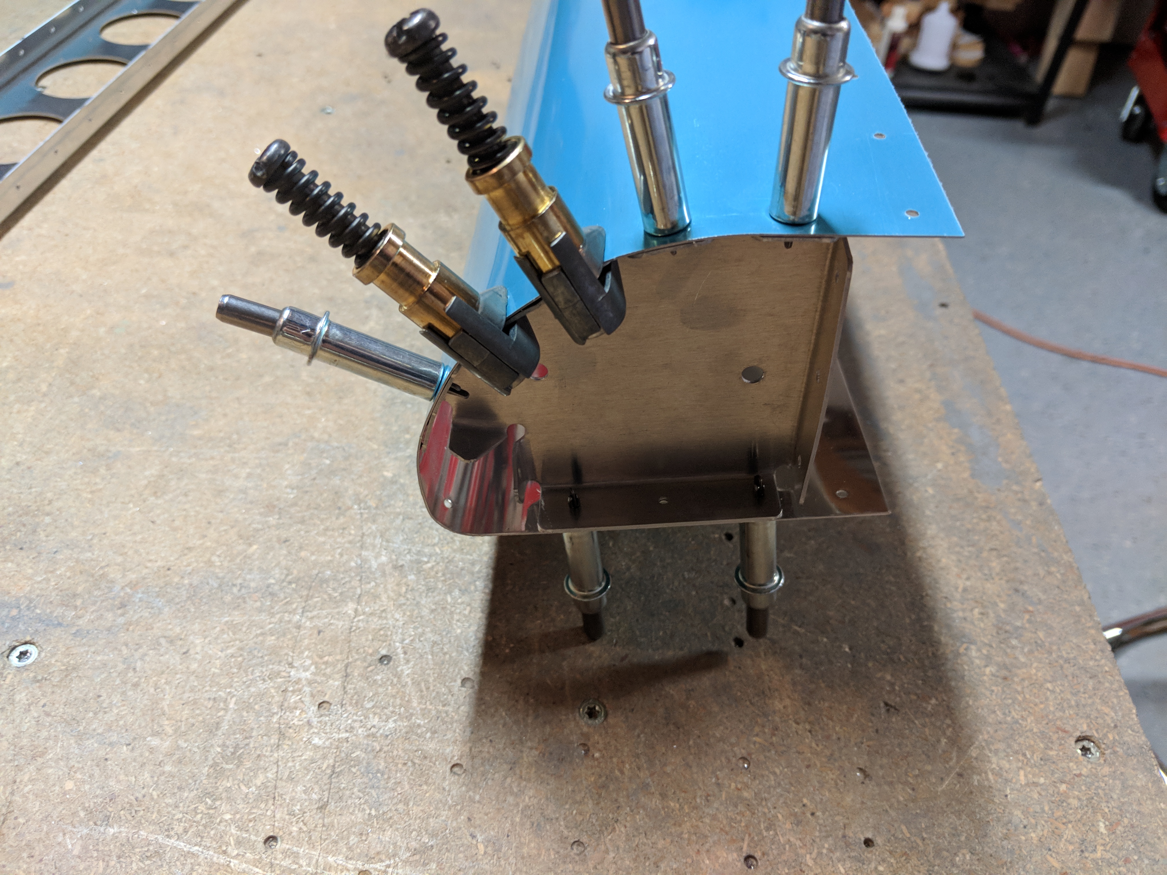
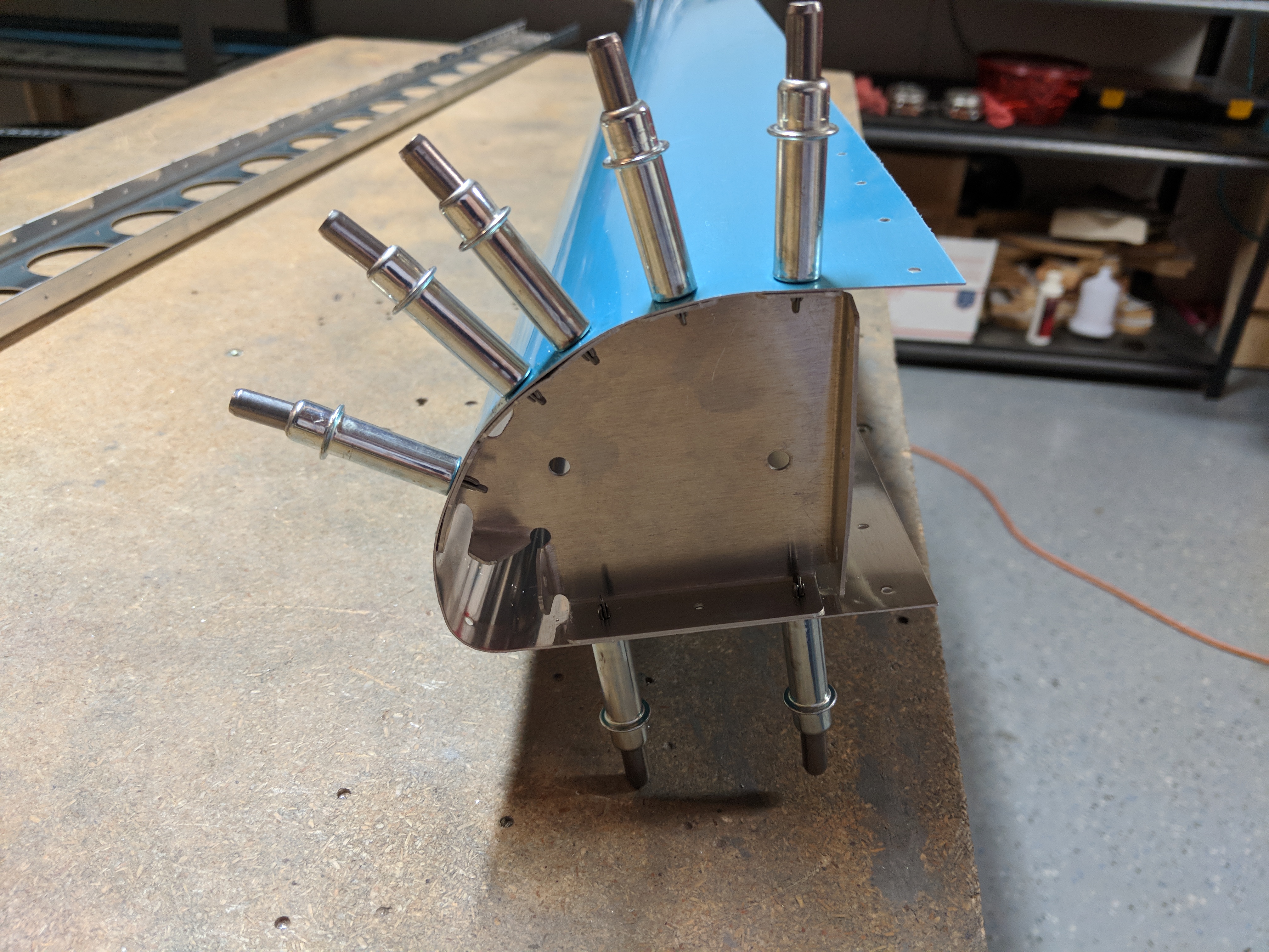
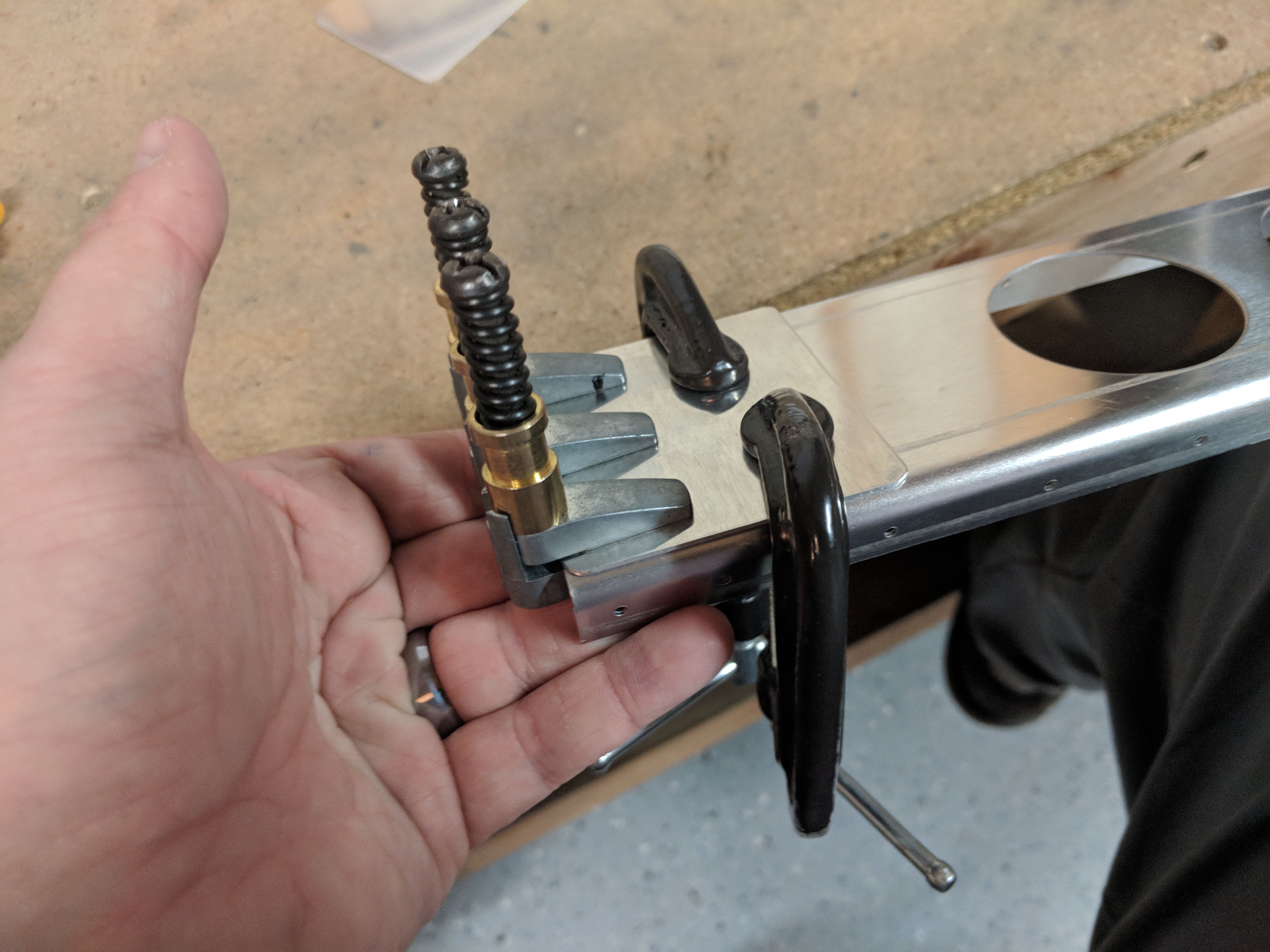
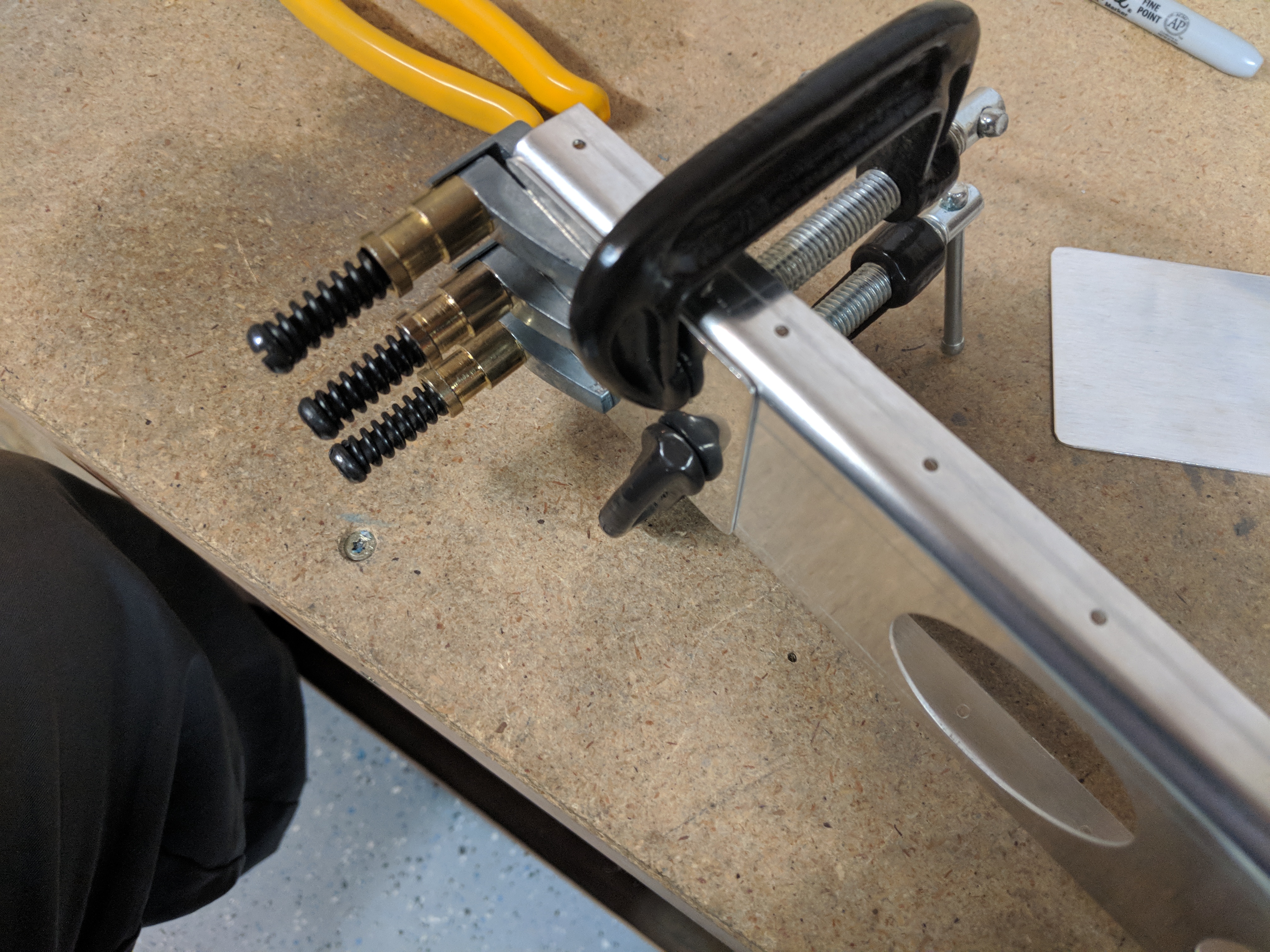
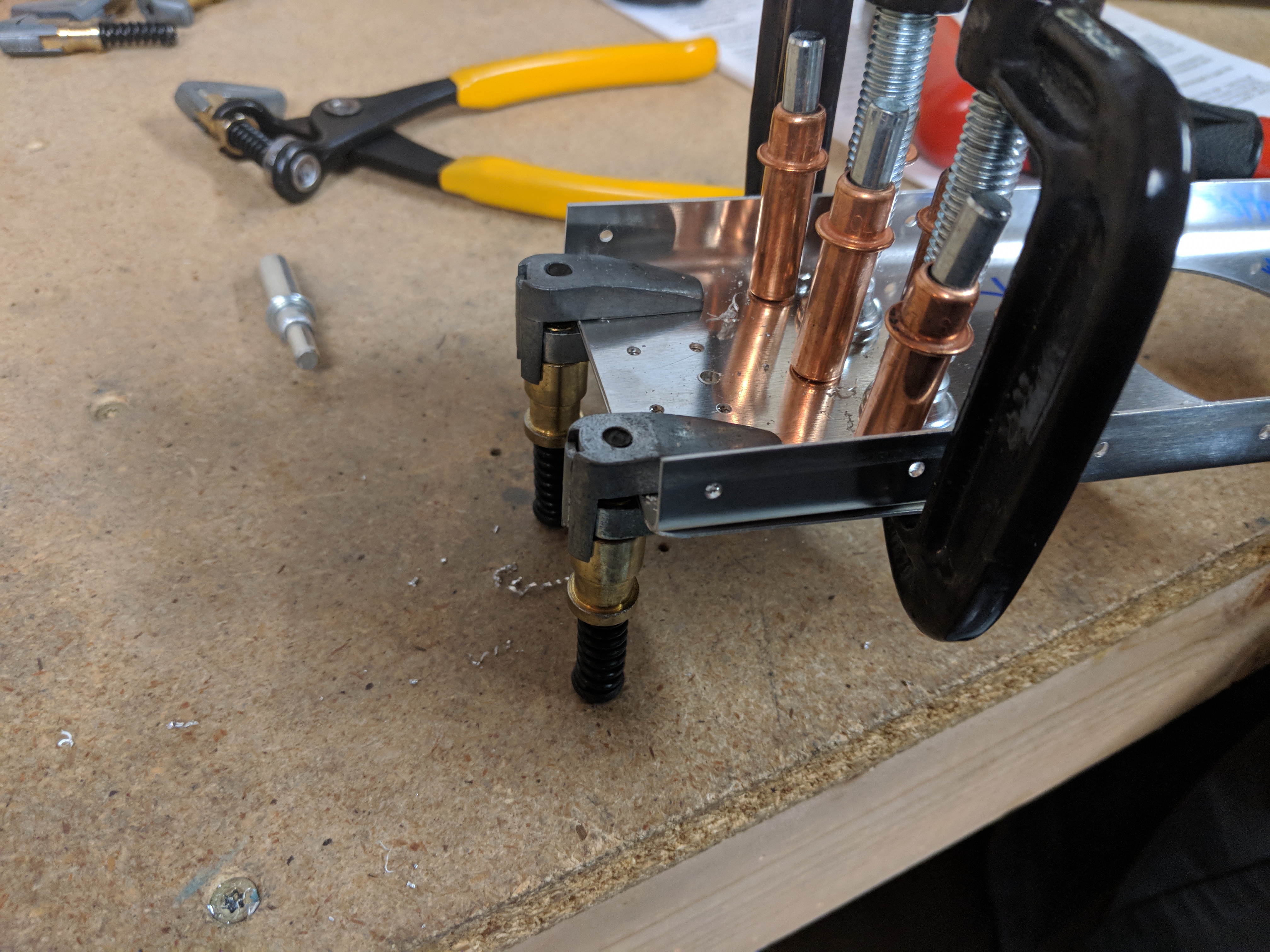
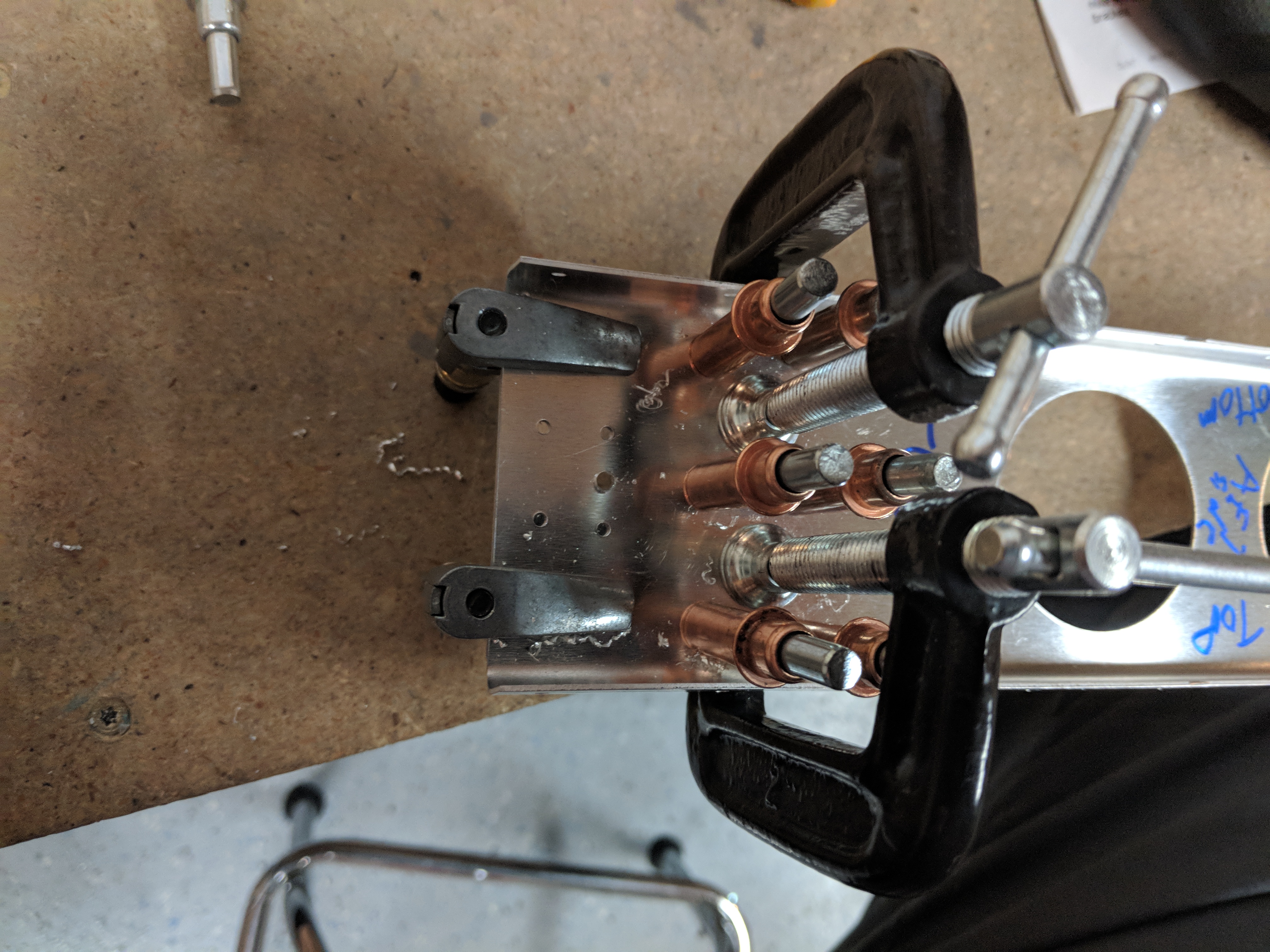
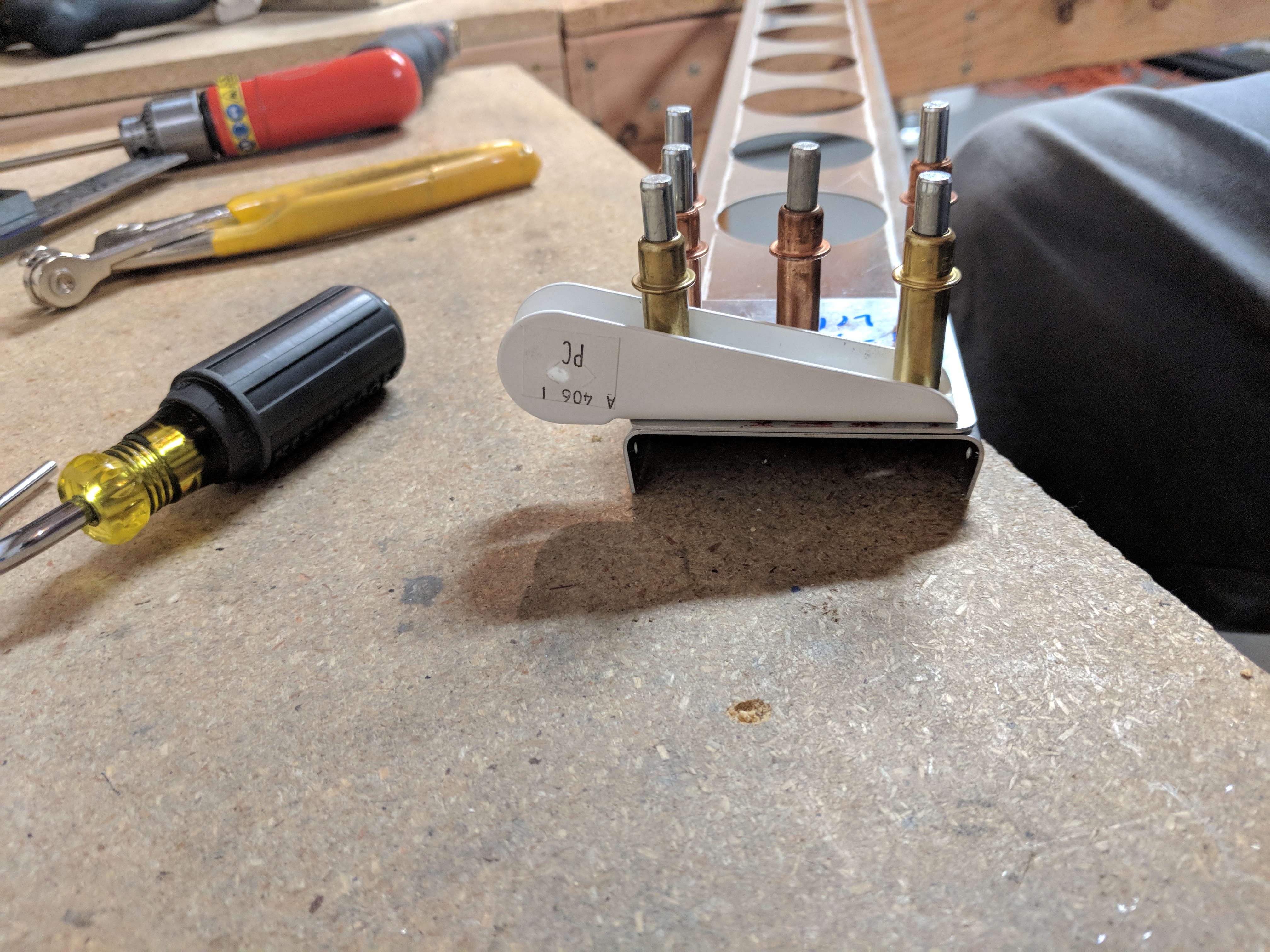
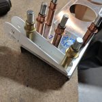
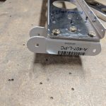
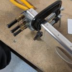
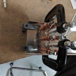
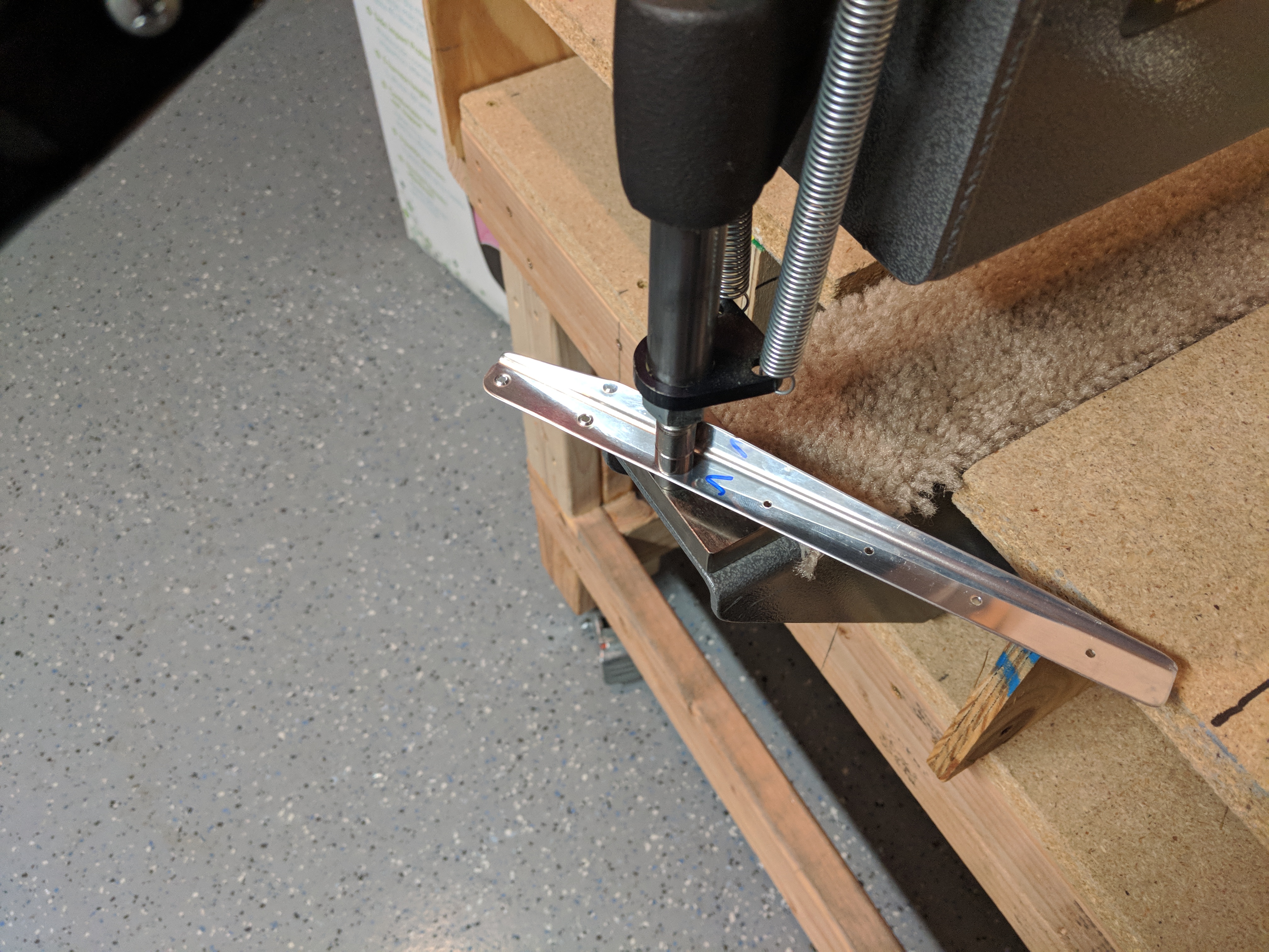
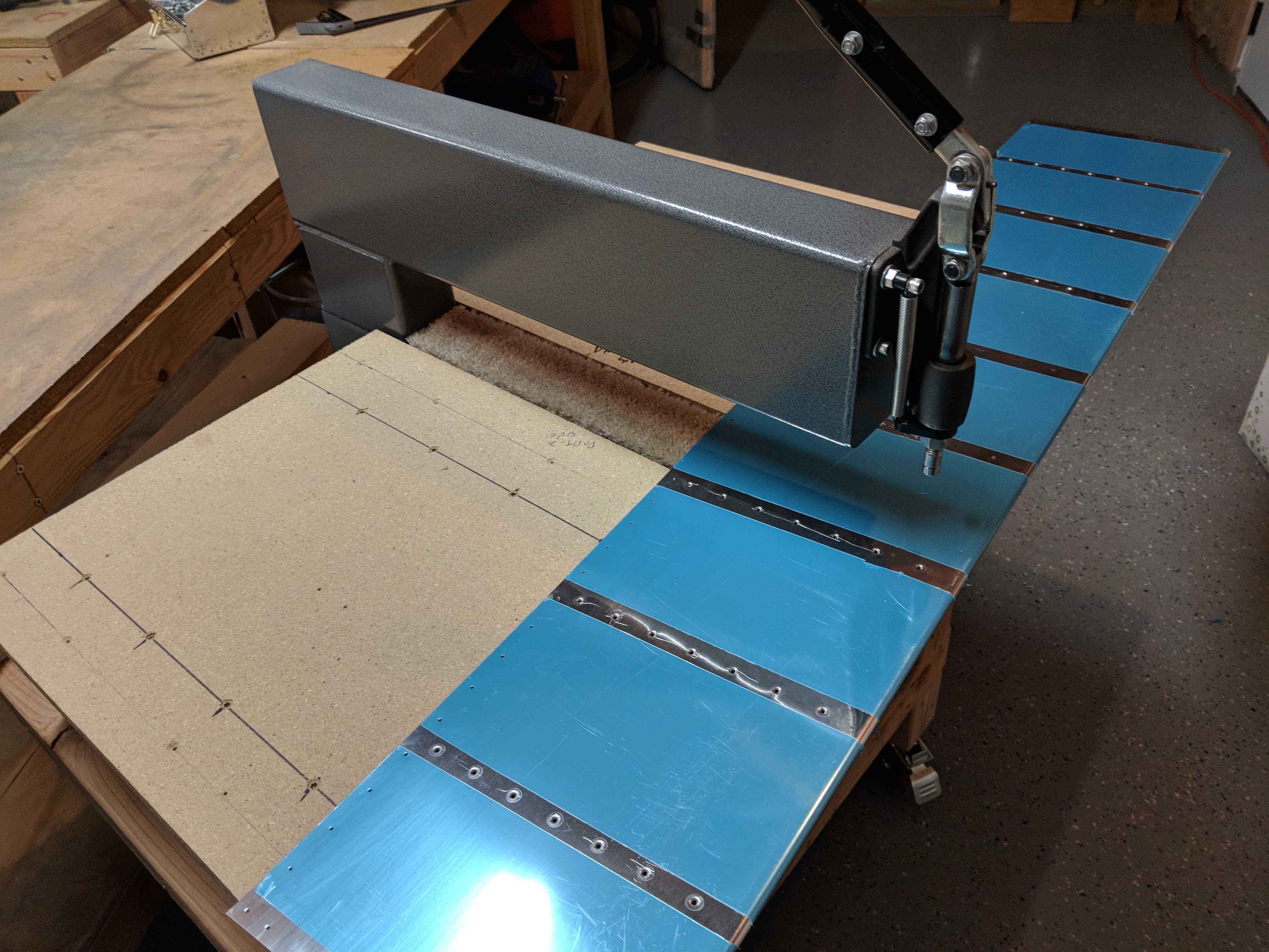
Any ways, carrying on, I decided to drill the last holes in the counterbalance just in case.  The plans has us remove the trailing edge skins, and re-cleco the leading edge back onto the spar for alignment, and then use a long 1/8″ drill bit to get to the last two holes we need to drill.  We go into one of the existing holes for the A-704 nose ribs on the bottom and then drill the hole into the counterbalance using the hole in the flange as a guide.  Like this:

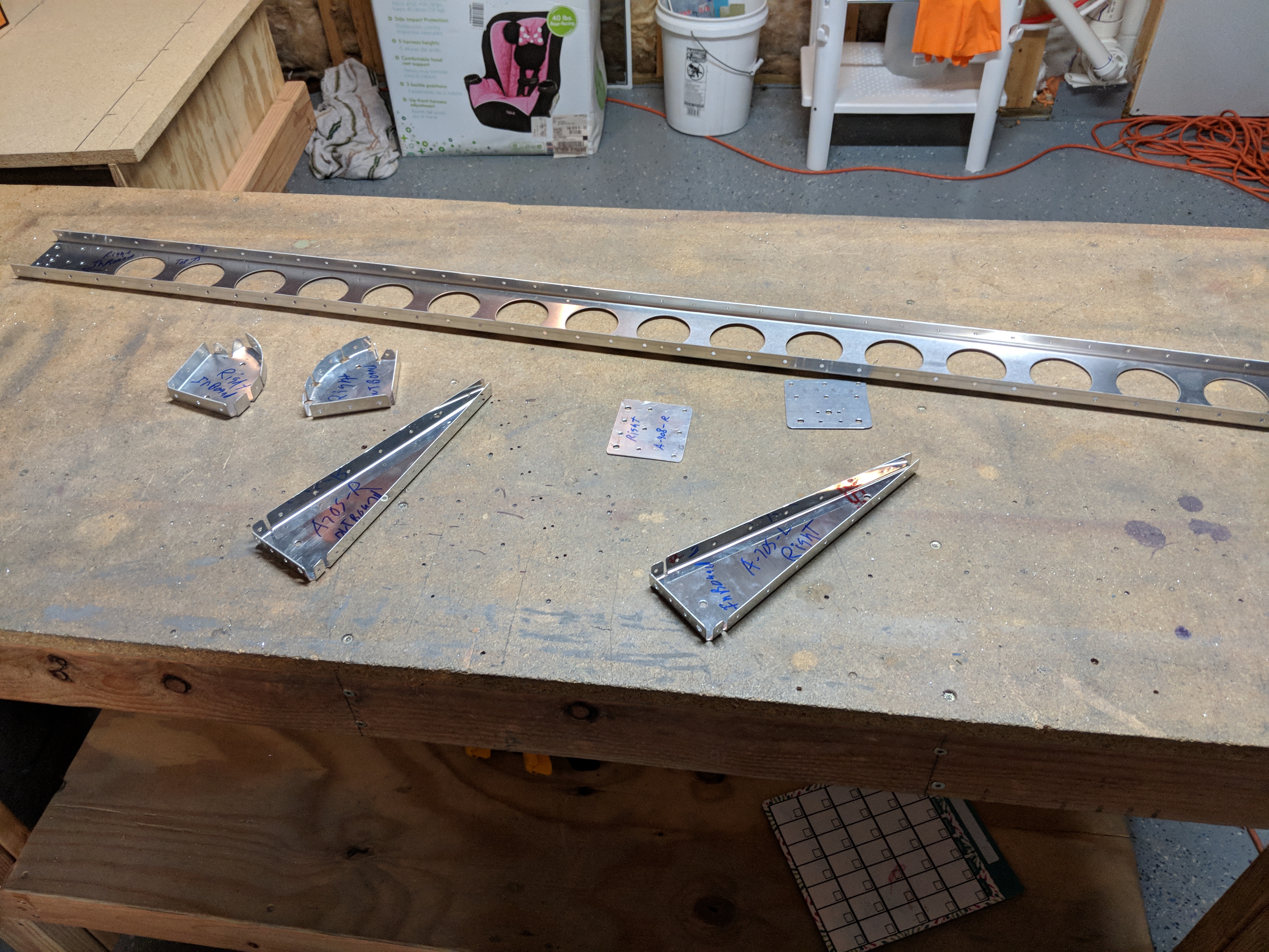
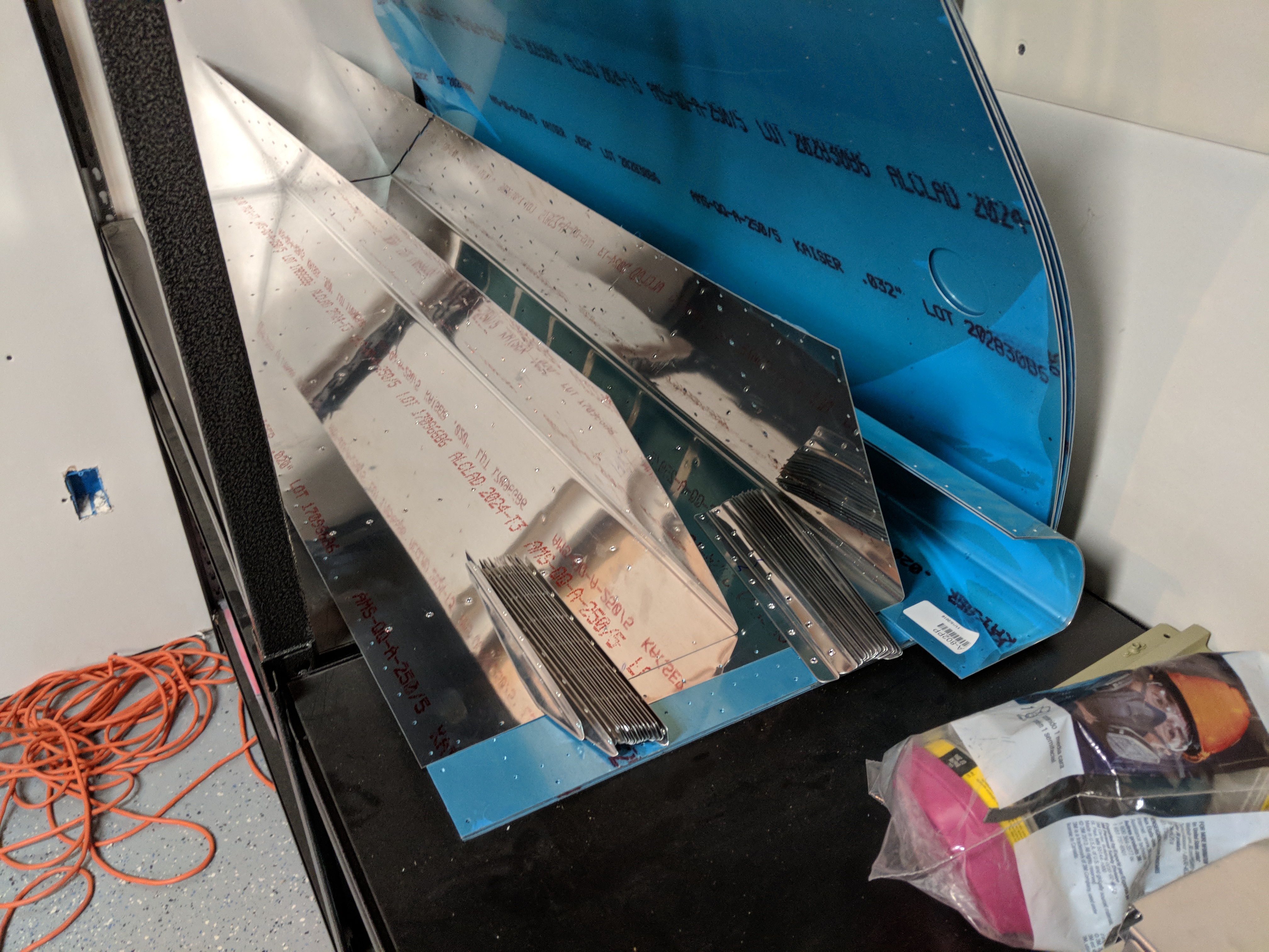
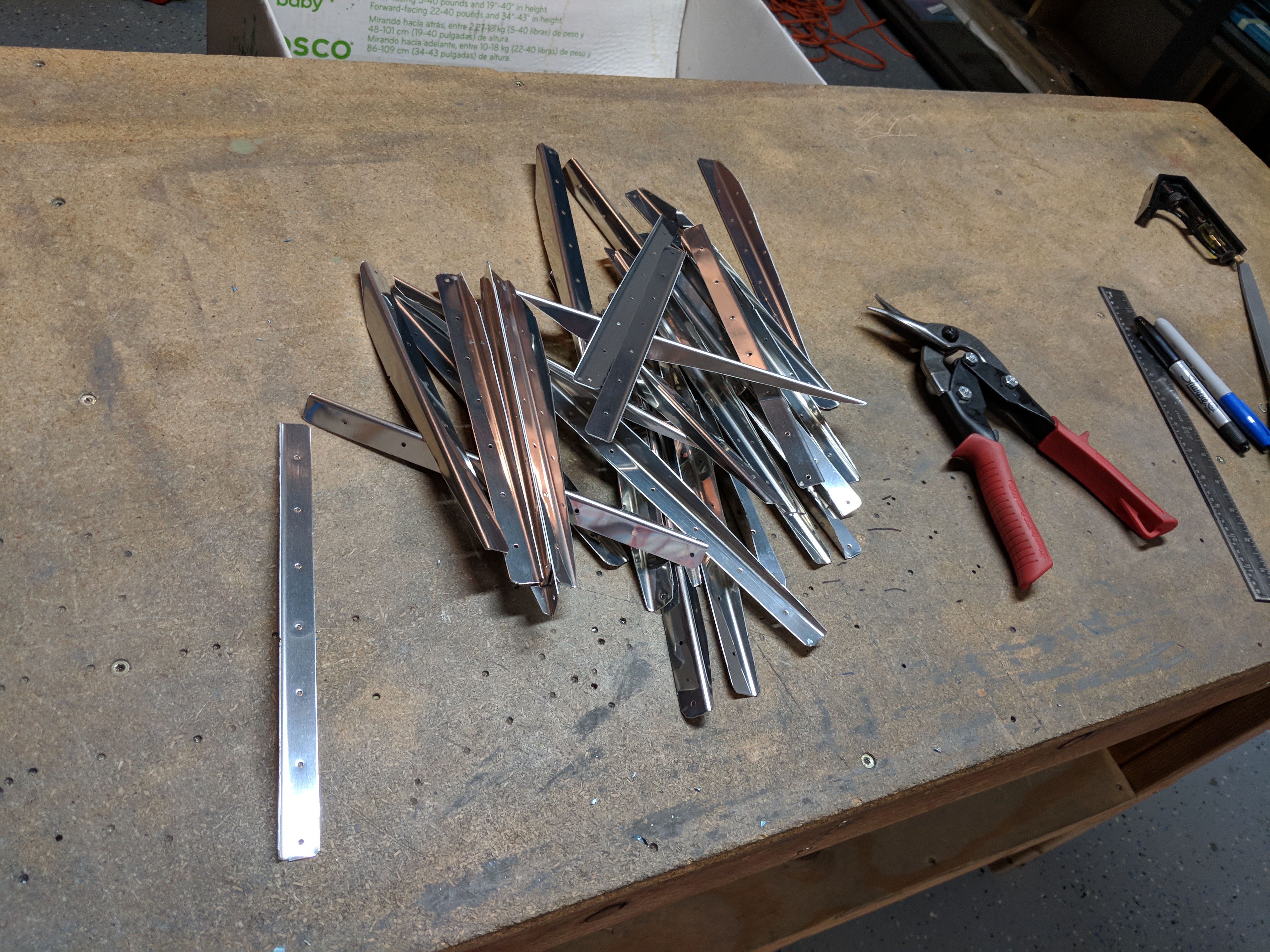
That worked out really well, and the last two holes were drilled into the counterbalance via the nose ribs. For here, I disassembled everything, and put the parts on the shelf until I get time to deburr, finish the edges and clean them up for priming.  Thats it for tonights session, I will do the right aileron in the same fashion tomorrow. Hopefully after I speak with Van’s I’ll get good news that my mess-up is fixable.  I am just glad that it happened on a part thats relatively easy to replace if need be! Especially since I haven’t spent the man hours prepping and priming it yet!  Heres all the photos from tonight:

Google Photos Link: https://photos.app.goo.gl/pSLIaZ02zXNSFpKD3

Hours Worked: 1.75

Bending the Aileron Skins

Bending skins is one of those tasks that make me nervous! Van’s ships the aileron skins with the trailing edge bent only just enough to form the trailing edge.  The reason is so that you can easily attach the stiffeners via backriveting.  The task itself is not difficult, but it seems like something that could go wrong, very quickly 🙂

The above photo shoes how much bend comes from the factory, along with my homemade bending brake I built during empennage construction.  I have it clamped on to my workbench level with the surface so I can slip the trailing edge of the skin into the “jowels” and make a nice, smooth bend along the length of the aileron.  You can see more details about how I made the bending brake here: https://theskunkwerx.com/rv7/bending-the-right-elevator-trailing-edge/

I slipped the trailing edge into the brake and held it firmly as I slowly bent the skins over using very light, even pressure.  I like to use the “sneak up” method, of bending a little, and then checking the fit…..and bending a little more as needed…and repeat until i have the bend just right. 

Eventually, after several rounds in the bending brake, I wound up with the aileron where I though it was close enough to do a dry fit.  Vans has us bend the aileron just until the skins gently lay on top of the spars.  In the photo above, I am about half-way there. Once I had it to where I thought was close, I clecoed the aileron skeleton inside the skin and measure the straightness. Per the instructions, Vans tells us that the skin should be straight, form the spar all the way right up to the trailing edge radius.  The radius itself should be around 1/8″, and the profile of the aileron should match the full size drawings.  Mine were REALLY close to the profile in the drawings, so I decided to use a straight edge to check the straightness.

The process goes like this: I lay the straight edge perpendicular to the leading/trailing edge and check to see if there are any humps, bumps, or divots underneath it.  A hump/bump means I don’t have enough bend, where a divot means I have too much bend.

SOOOOO close this time! One or two more bends and it’ll be perfect!  It’s very important to get this just right because I have heard horror stories of builders having heavy wings because of an aileron that isn’t perfectly bent.  Vans actually has a procedure that calls for “squeezing” the ailerons with your hands to help get rid of a heavy wing.  Its astounding such a small little control surface can have such a big impact, even when in trail.

After a few trips back into the bending brake (which includes unclecoing and re-clecoing) I ended up with a darn near perfectly straight skin!  Once I had the top side of the skin, I also checked the same on the bottom side, using the same procedure of measuring with the straight edge at every stiffener, and at every station between the stiffeners, including the very ends at the ribs.  Things doesn’t always go great, sometimes you get a little too much bend in one section:

As you can see in the photos above, I got a little overzealous with my bending brake on this aileron (The left one). While the rest of the aileron was fine, this inboard end needed to be un-bent per-se. You can see the little divot right under the straight edge. It isn’t much , but I want to go ahead and get it corrected while its easy to do.  So, I removed the skin and use my fingers and a piece of soft scrap wood and ever so gently bent the skins back out (opening the end up a bit) until I had the straight edge sitting perfectly level across these sections.  You can see where I marked them with an “X” to keep track. Once I had one aileron bent, it went back on the shelf while I bent its sister for the opposite wing following this same procedure. Now that I have these skins bent, I can move on to fitting and drilling the skeleton to the skins and continue on.  I’ll double check the straightness of both of these before final riveting, so I can make any corrections before closing up.  Here’s all the photos:

Google Photos Link: https://photos.app.goo.gl/MmT1Pd7YN7GKmYgJ3

Hours Worked: 1.5

Riveting the Aileron Stiffeners

Since the AKZO had plenty of time to harden, I decided to go ahead and rivet the stiffeners to their skins so I can continue on with the build process.  Since these are backriveted on, this was a very quick little build session, which was nice because I have TONS of other stuff to get done tonight….not airplane related.

I started out by inspecting all the stiffeners and skins to make sure I had done a decent job priming them.  There’s a few thick spots and a few thin spots but since this is just primer on the internal parts I am not worried about it.  It’ll do its job of preventing corrosion. I setup my rivet gun with the backrivet set, dug out the backrivet plate and setup the benches.  As the drawings call for, I used AN426AD3-3.5 rivets, stuck them in the holes for the stiffeners and then used some riveters tape to help hold them in place while I back rivet.

You can see on the right side of the back rivet plate, a piece of wood.  It’s almost the same thickness as the plate, so I use it to hold the skin level to make sure the stiffeners get set squarely against the skin. Then I placed a stiffener over the rivets and held it down with my fingers as I backriveted it to the skin.  I like to set the rivet in the middle, then work my way out to the edge of the skin. Then I go back and set the rivets from the middle, working towards the bend in the skin.  This way my stiffener is well attached and won’t get mis-aligned when I push the skin back to get the rivet gun in that space near the bend.

I simply worked my way along each stiffener this way, and then worked from the inboard end of the aileron to the outboard riveting the stiffeners on.  This process went pretty quickly, so I was done with each side of the skin in about 15 minutes or less.  Eventually I had both ailerons done and it was time to call it a night for this quick session.

I’ll work on bending them to their final shape tomorrow, I’ve got to dig out my bending brake I made for the empennage kit 🙂 Here’s all the photos from tonight:

Google Photos Link: https://photos.app.goo.gl/2ExONxvwMkvCttIl2

Hours Worked: 1

Priming the Aileron Skins and Stiffeners

I was pretty happy with the way the Alodine treatment turned out last night, so I figured I would go ahead and lay down some AKZO primer on them to see how well it sticks.  This is going to be a small primer session, with only doing the stiffeners and the skins for both the left and right ailerons.  My goal is to really test the alodine procedure to see if its going to be worthwhile on these smaller parts, but I do need to get these parts done so I can move on to the next step.

I started out by preparing the edges of the skins by running a bastard file to smooth off the high points form the shearing process.  Then i rounded off the corners. Next up was scuffing the skins with scotchbrite.  I will probably do these large parts this way since I don’t want to be spraying those chemicals around, and the large parts don’t fit into a bath solution very easily.  I scuffed them as I typically do, and the cleaned the skins with Acetone.   Once the paper towel was coming up clean, I put the skins in the booth and mixed up 4 ounces of AKZO to let it do its 30 minute activation.

While the AKZO was setting up, I donned a new Tyvek suit….well a cheap copy of one from Home Depot since I blew the crotch out of my REAL Tyvek suit.

This thing was no where near the quality of the Tyvek I normally buy from Amazon, and it was actually more expensive! It will do the job though, but I am going to order a replacement Tyvek suit tonight, because this thing was hot and didn’t seal around my facemask like the Tyvek branded ones.

Finally, it was time to shoot the AKZO.  I gave the Alodined parts a couple of normal passes with the AKZO, as I like to spray a light mist instead of a heavy dose in one application.  I will note, its a bit harder to tell if you have good coverage on the parts since the Alodine is a dull, gold color, it sort of blends with the AKZO’s green color.  On natural, scuffed and clean aluminum, its easy to see your coverage even in low light, like my booth.  But, its not enough to hinder things.  I’ll probably stick a decent light in my booth anyways, as I have been meaning to do that for a long time now.  Maybe a nice LED shop light.

I did use up all 4 ounces of the primer I had mixed. I had enough to fully cover all my parts and skins, and even a little left to use on touch ups.  Here’s some shots of the parts as they are drying in the booth:

I’ll let those guys harden over a day or two and then start the next step: back riveting the stiffeners to the skins.  I still have a little work I can do on the other parts, like deburring and edge finishing in the meantime.  Thats something for tomorrow.  Thats all for this session!

Google Photos Link: https://photos.app.goo.gl/JLnZJWvuA37qWhAr2

Hours Worked: 2.25

Alodining The Aileron Stiffeners

This sort of a two-for-one post.  My Alumaprep and Alodine came in this week, and in anticipation of this new process, I installed a utility sink in the airplane factory.  I’ve been wanting a utility sink in my shop for a while now for various reasons, and this was the kicker that made me install one.  I had a nice little place picked out for it, right next to a 3″ sewer line and hot/cold supply lines.  Thankfully, the builder installed PEX lines in my house, so a couple of Sharkbite connectors is all it takes to plumb this sink in.  Whoever came up with the idea of PEX and Sharkbite push-fit connectors….I salute you!

Anyways, I am not counting the hours I spent installing the sink in the build.  So tonight I decided to try this whole Alumaprep and Alodine process.  Part of building an experimental aircraft is learning the techniques!  I mixed both of them into the proper ratios for a bath solution, and gave it a shot.  I wanted to test the lazy scenario first:  Not scuffing or cleaning the parts, and letting the alumaprep do that for me. To be safe, for my first time I figured I would just do a small batch and focus on the stiffeners (I hate scuffing those suckers).  SOOO, I put them in some tubs and poured my alumaprep bath over them until they were submerged.  At first I grabbed the stiffeners for the RIGHT aileron first to keep them sorted with the right side.

Per the instructions, I let them sit for 5 minutes in the bath solution and watched the bubbles take away all the dirt and alclad.  Once the 5 minutes was up, I pulled them out and let the Alumaprep drip back into the tub and then rinsed them off in my sink.

Now its time for the Alodine.  I done the same procedure in the alodine bath. I stuff the right stiffeners in the Alodine while I put the left stiffeners in the alumaprep.

When the Alodine bath was ready, I pulled them out and dunked them into fresh water in the sink and rinsed them off really well and left them to dry. Meanwhile, the last left side stiffeners were ready to be rinsed and then dunked into the alodine.  When their alodine bath was done, I rinsed them and set them to the side to dry.

I am not quite sure if they got “done” enough, but they have that pretty golden finish and they are a satiny feel.  I think AKZO will stick really good to these things.  I am going to let them dry overnight and then check on them in the morning.  If they look fine, I may end up shooting some primer on them.

I still think I might get some Bon-Ami cleaner and then clean my parts with it and a gentle scrubbing with a scotchbrite pad to get them more prepared for the Alumaprep bath.  Maybe this will give the primer a better surface.  I will say this….I much prefer this process over the hours of scuffing and cleaning with acetone! Here’s the photos from tonights work:

Google Photos Link: https://photos.app.goo.gl/Vf0NnRRTX0DzFGRB2

Hours Worked: 1.25

Drilling the Aileron Nose Ribs and End Ribs

I am kind of running out of tasks to do until the Alumaprep and Alodine get here.  I was able to get a little work done  tonight though, only about an hours worth.  The next step in the instructions tells us to match drill the A-704 nose ribs, fluting the widest tab as necessary.   Some of mine didn’t need much fluting and one did.  It’s a process of trial and error until you get just the right amount to bring the flanges back into alignment, using the skins as the guide.

Most of the holes in the nose rib are pre-punched, but there’s two holes that we need to back drill using the skin as a guide, once we have the flanges aligned.  I used some cleco side clamps to hold everything in alignment while I drilled.

This is the same process on both the inboard and outboard nose ribs,  and I went ahead and did both the left and right ailerons.

Next up was to match drill the A-705 end ribs to the spars.  The plans are pretty explicit in saying to make sure you have the proper one, as they are not symmetrical, so I double checked that the parts were in the right orientation, with the tooling holes towards the bottom of the aileron.  I clecoed the end ribs on, and match drilled all the #40 holes first.

Lastly, I fired up the #12 drill bit, and back-drilled the bolt holes for the aileron mounting brackets into the end rib. I repeated this same process on the right aileron.

Once I had the nose ribs and end ribs done for both the left and right aileron, all that was left was to deburr the holes, which only took a few minutes.  I still need to deburr the edges on all the aileron parts, including the skins, but I think I will save that for another build session. Maybe that will be about the only thing I can do until the Alumaprep and Alodine get here.  Here’s all the photos from tonight:

Google Photos Link: https://photos.app.goo.gl/FJEqsrxbtxVj798G2

Hours Worked: 1

Fitting the Aileron Mounts

I ordered 2 quarts of Alumaprep 33 and 2 quarts of Alodine 1201 (Or whatever Bonderite is calling it now that they own it).  The total was just about $100 from Aircraft Spruce. BUT, that’s not going to stop build progress 🙂  Tonight I moved on to the next step, which was working on the mounting brackets for the ailerons.  Well, the brackets themselves are already formed from steel, but we have to make a doubler plate, and then match drill everything to the spar.

The work started out by pulling the A-403PP-L/R aileron spars from the shelves and removing the blue plastic from them.  I have decided to work on both the left and right ailerons since these tasks are the same for both sides, that way I can prime them all together.

Next I had to make the A-408 spar reinforcement plates from 4 pieces of .040″ 2024-T3 alclad that Vans ships with the kit.  I found the pieces in my parts bins, and was surprised to see that they were actually already cut to size!  All I had to do was round the corners off drill’em!

The plans is pretty specific about making sure you mark the spars correctly, because they are not symmetrical, so I took a little time to study the plans and made sure I had mine oriented correctly and marked everything up.

Then I put the reinforcement plates on the correct side of the spar (leading edge side), and made sure they were squared up, and clamped them down.


Since these plates have no pre-drilled holes, good clamping and proper alignment are necessary for when we start back-drilling using the spar as our guide.  As I drilled each hole, I made sure to follow it up with a cleco to keep everything aligned.


I completed drilling on the left aileron first (both inboard and outboard plates), since that is the side depicted in the Vans drawings, and once I had it done, I did the same to the inboard and outboard plates on the right aileron.  After the plates were back-drilled to the spars, It’s time to match drill some of the nicely painted mounting hardware that ships in the kits.  The A-406-1 outboard bracket and the A-407-L/R inboard brackets are all made at the factory and come painted with some nice white paint.  These are steel parts and are very nicely done. We have to match drill them to the spar using a #12 bit to make sure everything will bolt up correctly using AN3-4 bolts.

Heres the A-406-1 outboard bracket drilled and cleco’ed:


And here’s the A-407-L-PC inboard bracket match drilled and then test fitted using the AN3-4 bolts.  I do not have the nuts on, and these are just laying in the holes so I can check alignment.  They fit good!

Once I had the left side done, I moved on the right and did the same there. I also went ahead and deburred all these holes in the spars, reinforcements plates, and brackets so they’d be ready to go.  There was one last little step.  There’s a few holes that will get AN426AD3 rivets in them, so I went ahead and countersunk the holes that they’d go in. I just used my hand deburring tool and a AN426AD3 rivet to check the right depth since it was only a few holes…not worth digging the microstop out and setting its depth.

Its kind of hard to believe that those 4 little plates and 4 brackets took almost 3 hours of work to fit and drill, but they did!  Although, there’s probably a good bit of time in there just looking over the plans and drawings 🙂  Here’s all the photos from tonights work:


Google Photos Link: https://photos.app.goo.gl/TjGrVqpVZ6OW5kb92

Hours Worked: 2.75

Drilling, Deburring, and Dimpling the Aileron Stiffeners and Skin

After dealing with Unicoi Aviation’s Taxes, our family taxes, and end of year for work, I decided to hit the shop and do a little building.  I actually made decent progress on the build tonight, and have both ailerons ready for assembly.  I had finished making all of the stiffeners for both ailerons, so the next step was to fit them all the the skins and get them match drilled. But first, I have to remove all this blue plastic:

Then,  I clecoed the stiffeners to both sides, and then match drilled them to a #40, and marked the stiffeners to which side they belong on.


After getting all of the stiffeners match drilled and marked, I removed them for the next step: Deburring.  This is the same old process I have done hundreds of times: 1. Deburr the stiffeners, both sides, then 2. Deburr the skins both inside and out.  As always I took a lot of caution on the skin, because the ailerons uses thin .025″ skin, and I didn’t want to knife edge the holes.   Once I had the deburring done, it was time to dimple everything.  This is a little different from my normal process, because I need to rivet the stiffeners to the skins before I can proceed to the rest of the steps.  I have also decided that I am going to use Alumaprep 33 and Alodine to help get these stiffeners (and in the future, the wing ribs) ready for priming.

Once I had all the parts deburred, I decided I had enough steam left to just go ahead and dimple these guys and be done with them.  I used my DRDT-2 dimpler to make quick work of both the stiffeners and the skins:


After getting both the left and right ailerons done, these parts will go back on the shelf for a little while.  I’ll order some Alumaprep33 and Alodine so it will be here next week, ready to go.  The good thing, I can go ahead and get the next couple of steps done while I am waiting for that shipment.  I’ll get the doubler made, and the spars ready to go. Thats where I decided to call it quits for the night.  Here’s the last photos of my parts tucked away on the shelf….for now.

Google Photos Link: https://photos.app.goo.gl/OXt3RPYbVeZiRuf93

Hours Worked: 3.0

Making the Aileron Stiffeners

Changing of the Blueprints! I started the ailerons tonight.  Having finished up the flaps, the next logical step is for me to do the same for both ailerons.  After looking over the plans, the first step is…..making stiffeners!  Soooo much excitement /sarcasm.  Honestly though, the ailerons look to be a little easier than the ribs, so I’m looking forward to getting them done.  The work starts with us finding our A-710 stock and cutting as prescribed in the plans…..all 32 stiffeners.

Now I cut out the stiffeners from these 8 pieces of stock to create 32 smaller pieces that get trimmed a little bit more. See the detail below on how Vans has us trim these smaller pieces to actually become the stiffeners.


Image 2018-02-28 at 11.14.14 PM.png


And eventually I ended up with a pile of rough cut stiffeners like this:

This is where I realized I did something pretty dumb.  You see that blue plastic film?  Yeah, it has to come off, but I didn’t think far enough ahead to just go ahead and remove while I only had 8 BIG pieces of aluminum to remove it from….instead I cut all my stiffeners, and THEN had to remove this blue film…..32 times, instead of 8. Oh well, I’ll remember to do it better the next time and save myself some time and fingertips. heh.


Finally, it was time to deburr all the edges to get rid of the roughness and the cutouts to show us where to cut.  I used my scotchbrite wheel to make quick work of this and was able to complete all the stiffeners in this one session.

That was all I was able to get done in this build session.  It will give me a good starting point for the next time, as I’ll probably start fitting and drilling these things to the skins. I am seriously considering using alumuprep and alodine for these parts instead of the scuffing and acetone cleaning.  Stiffeners are not very fun to scuff, and there is A LOT of these things for the ailerons.  I’ll probably be putting in an order to Aircraft Spruce pretty soon to get this done, as well as the ribs.  Heres all the photos for tonights work:


And heres a short time-lapse I shot to prove I am the guy building the airplane 🙂


Google Photos Link: https://photos.app.goo.gl/SplOMZizQigF3Tnz2

Hours Worked: 2.25