Drilling Wing Ribs for Wiring and Plumbing

Back on the ribs tonight.  Since I have finished up the control surfaces for the wings, and I am still needing to build my wing stands, the only thing I can work on is the holes for my conduit and pitot and AOA plumbing in the wing ribs.  I have been putting a lot of thought to this issue over the past few weeks, and I have decided to drill two extra holes in my ribs, and enlarge one of the tooling holes. The session started with me looking over the recommended wing wiring diagrams from Vans, and then looking at what other builders have done.  I also unboxed my pitot-static-AOA plumbing kit from SafeAir1 and checked the outside diameter of the tubing used to make sure I didn’t over size my holes.

I have decided to drill the suggested 3/4″ hole at the bottom portion of the ribs, between the forward and second lightening holes per the Vans recommendation. I will run the 5/8″ nylon conduit that Van’s sells in these holes and I’ll use it for the majority of wiring in my wings.  In addition to this larger hole, I am going to drill an additional hole sized to 3/8″ just above the forward and center tooling holes in the ribs.  Then I’ll open the smaller tooling hole to 3/8″ as well, and use these two 3/8″ holes for my pitot and AOA tubing, protecting them with a snap-in bushing.  This illustration gives a better idea of what I want to do:

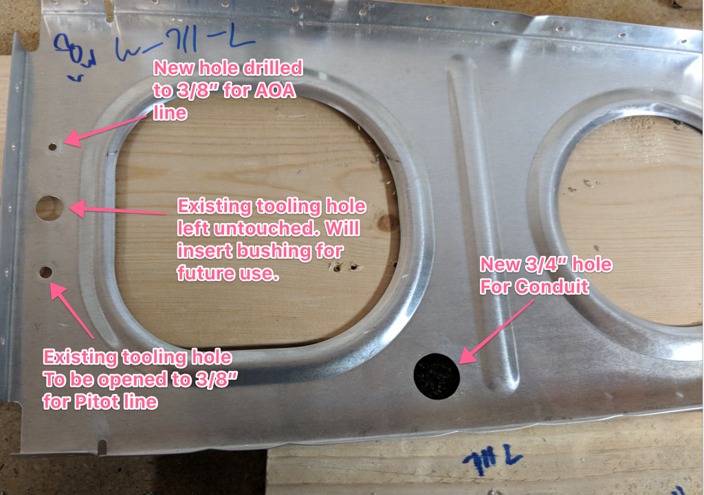
I will probably not immediately use the existing 1/2″ tooling hole on the forward edge of the rib, but I will probably go ahead and stick in a nylon bushing just in case I want to use it in the future.  I started out by measuring out where I wanted to put the 3/4″ hole. Vans just gives us a suggested location of “towards the bottom of the rib, between the first and second lightening holes”. I did some measuring and decided roughly where I wanted the center of the hole to be. Then I used a #30 drill bit to drill the center.  I then measured our equidistant from the 1/2″ tooling hole at the forward end of the rib and tried my best to get the new hole to be symmetrical to the existing holes.  It really doesn’t matter, so long as I drill the holes in the  same locations (roughly) in each rib.

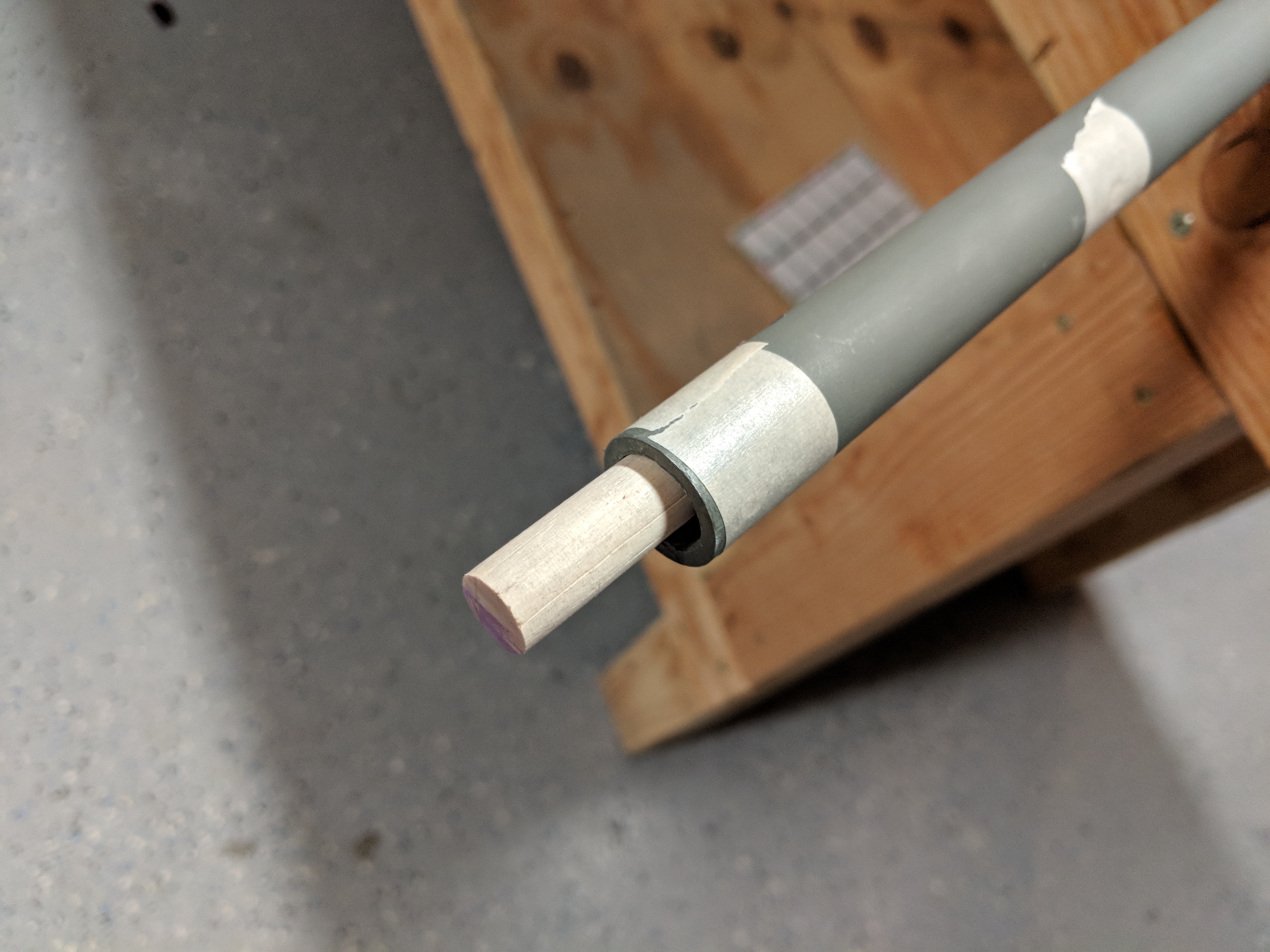
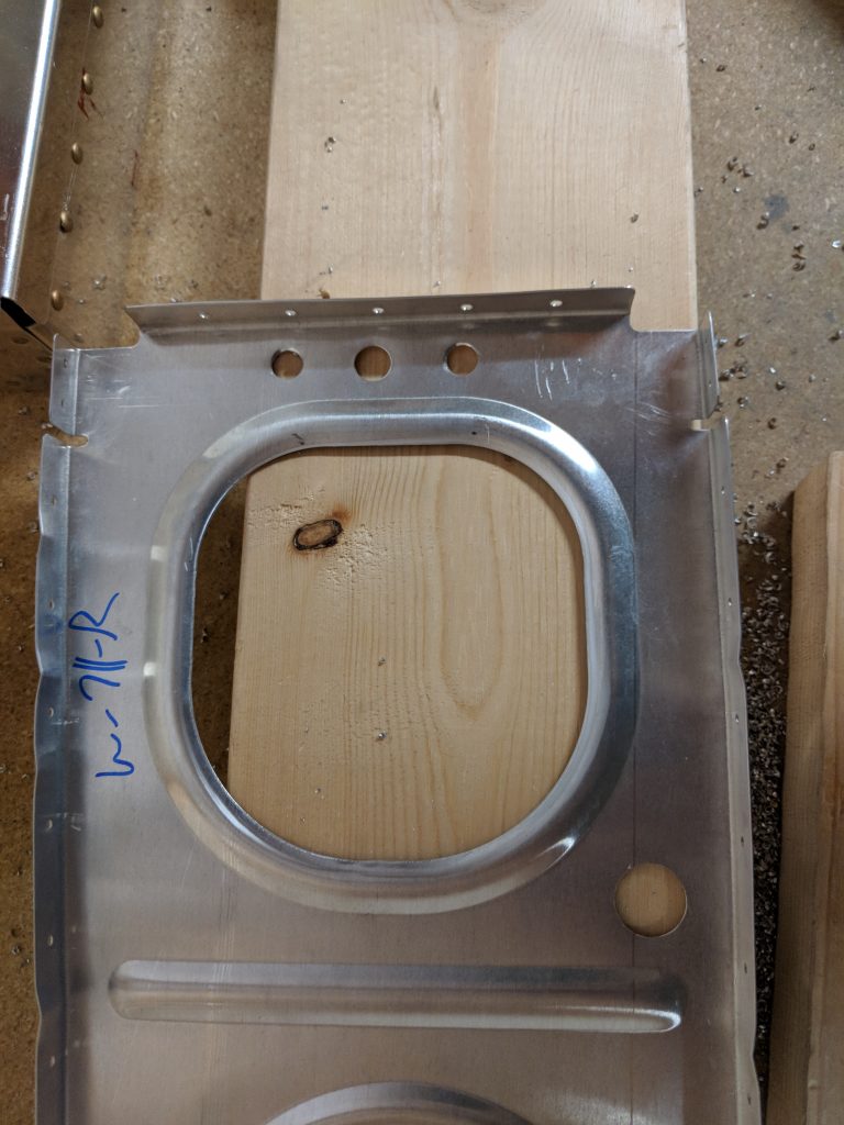
I drilled the new holes with a #30 to pilot the holes, and then I made a simple jig so I could transfer the holes to the rest of the ribs repeatedly and get the location exactly the same each time. I had a scrap chunk of 2×4 that worked great for this purpose.

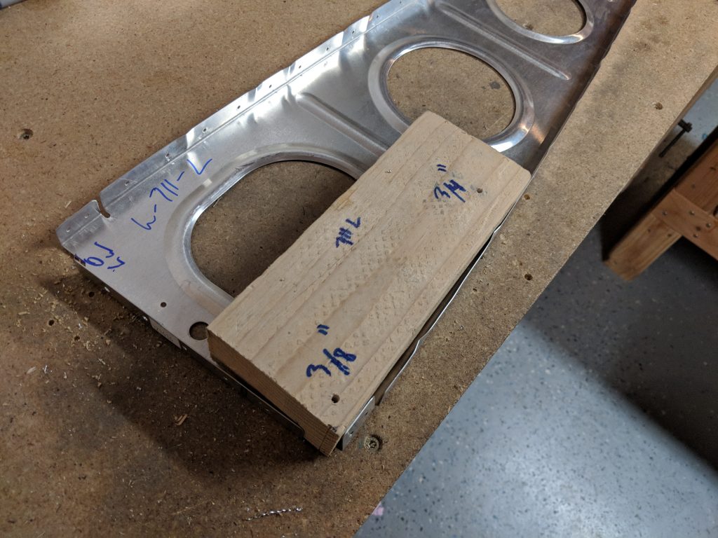
I just placed the 2×4 in the bottom corner of the rib, held it securely and transferred the hole I marked and drilled into the board.  I did this for each of the new holes.  Once I had the bottom hole (marked as 3/4″ on the board) drilled in the rib, all I have to do is slide the 2×4 to the top of the rib and match drill the new 3/8″ hole in using the guide marked as “3/8” on the board.

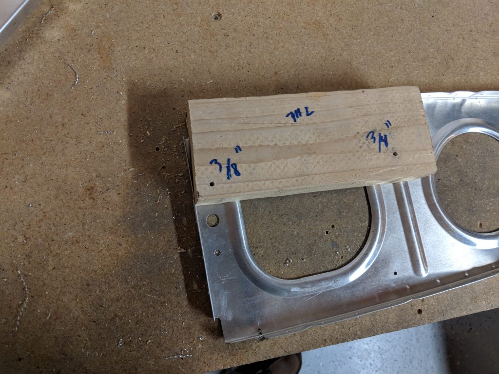
The only catch is this template/jig only works for the “left handed” ribs.  So, instead of making a whole new template for the “right handed” ribs, I just placed the left handed and newly drilled ribs on top of the right handed ribs flanges facing away from each other and back drilled the new holes.

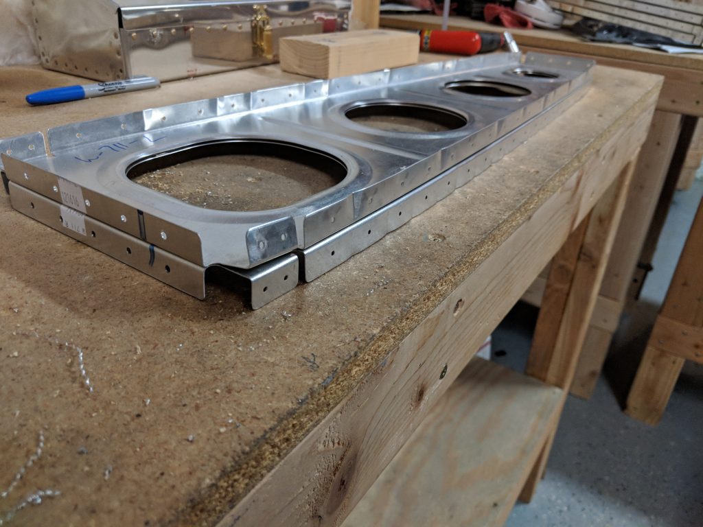
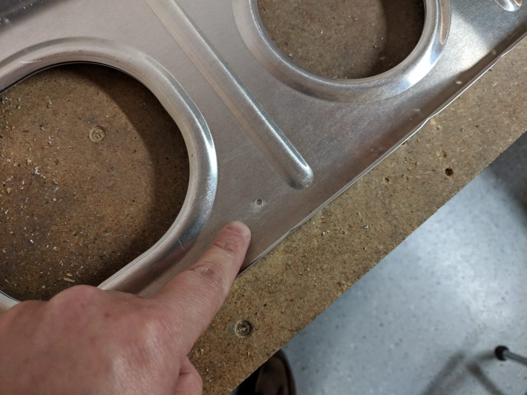
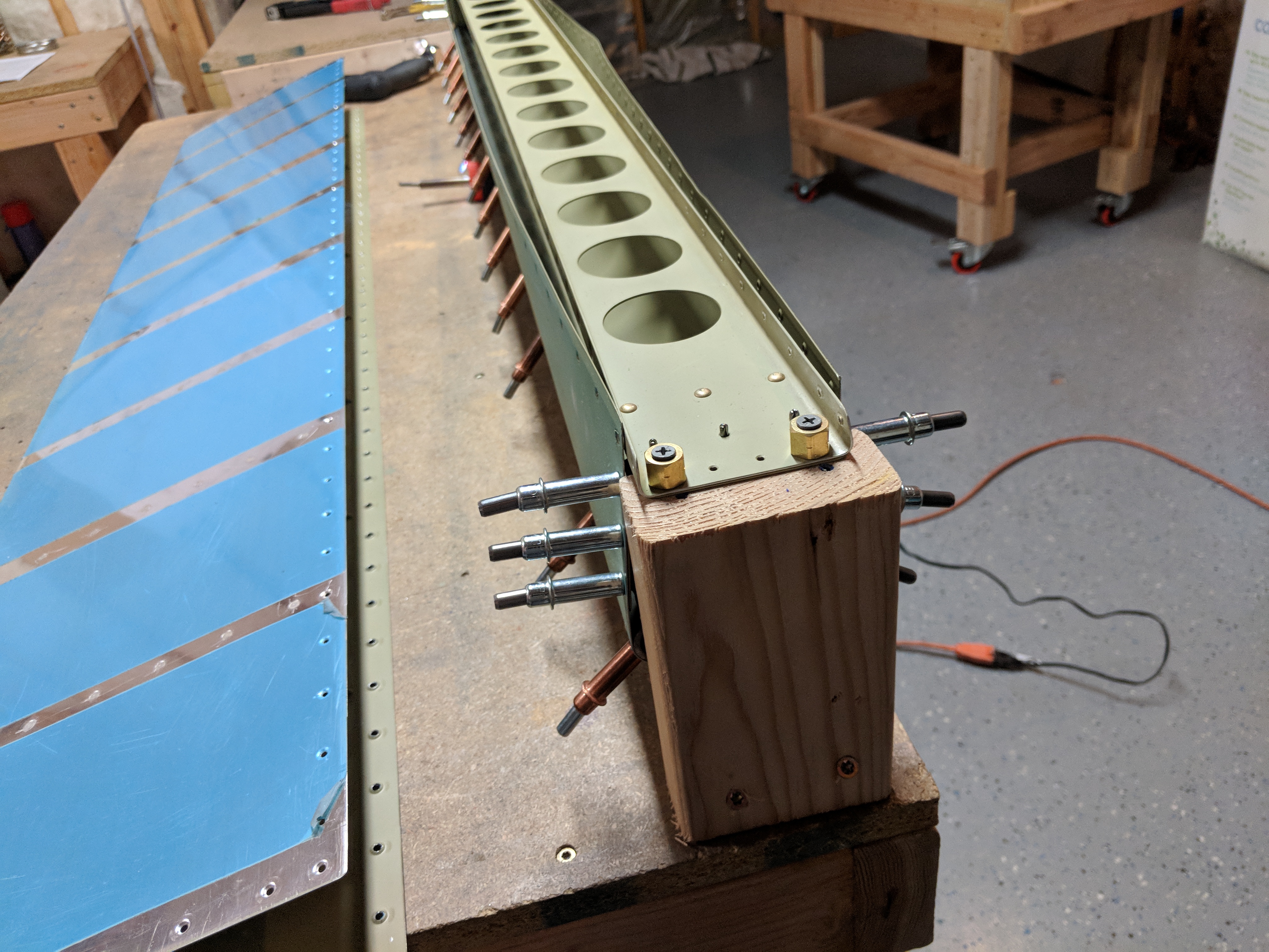
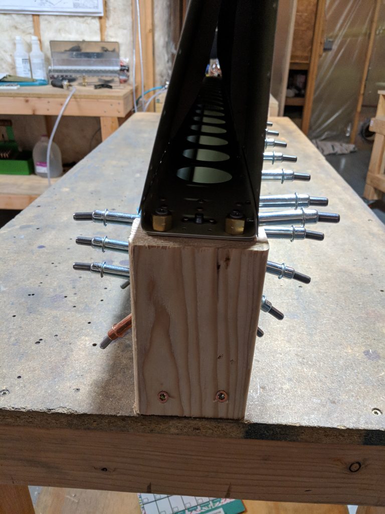
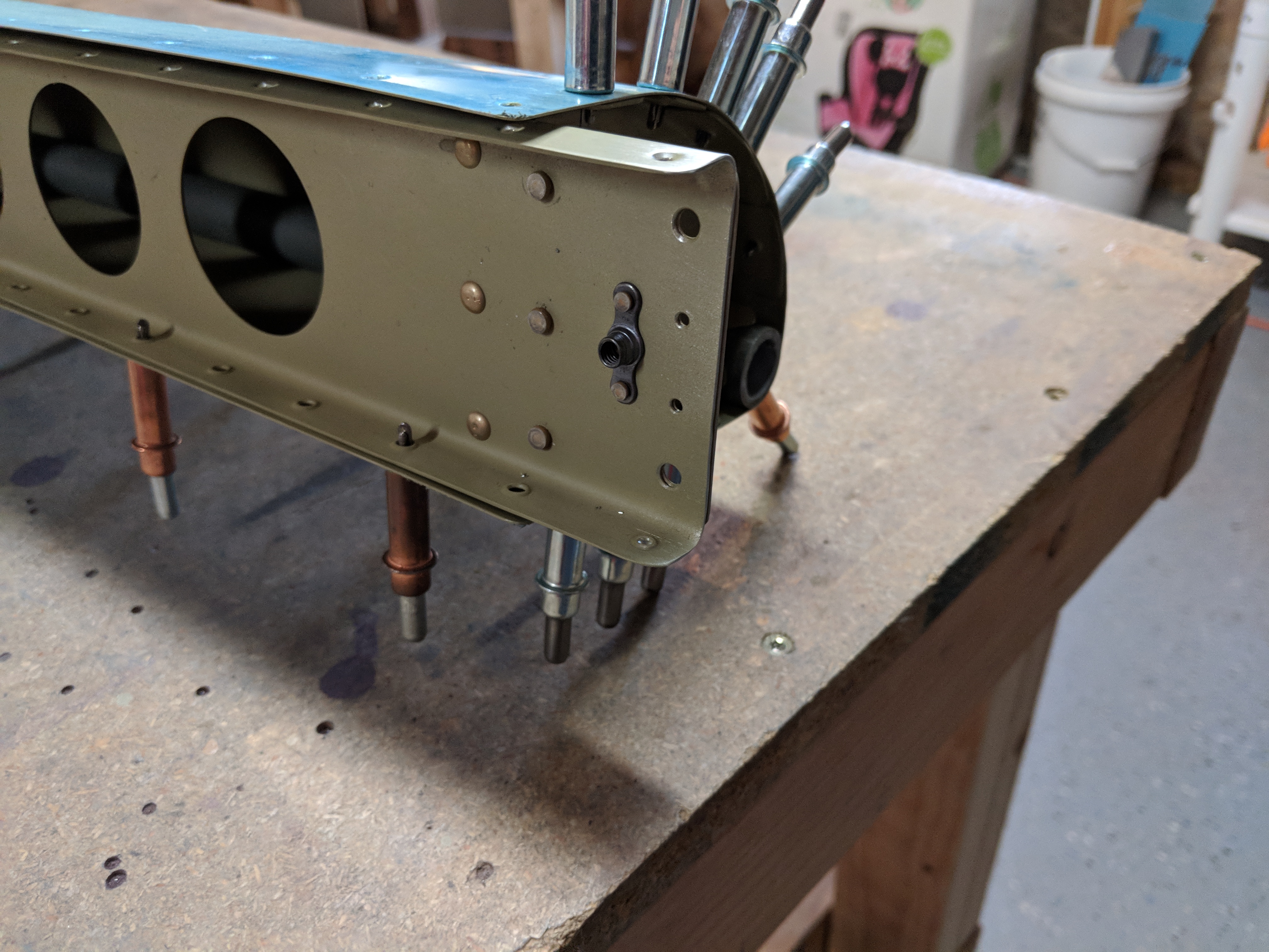
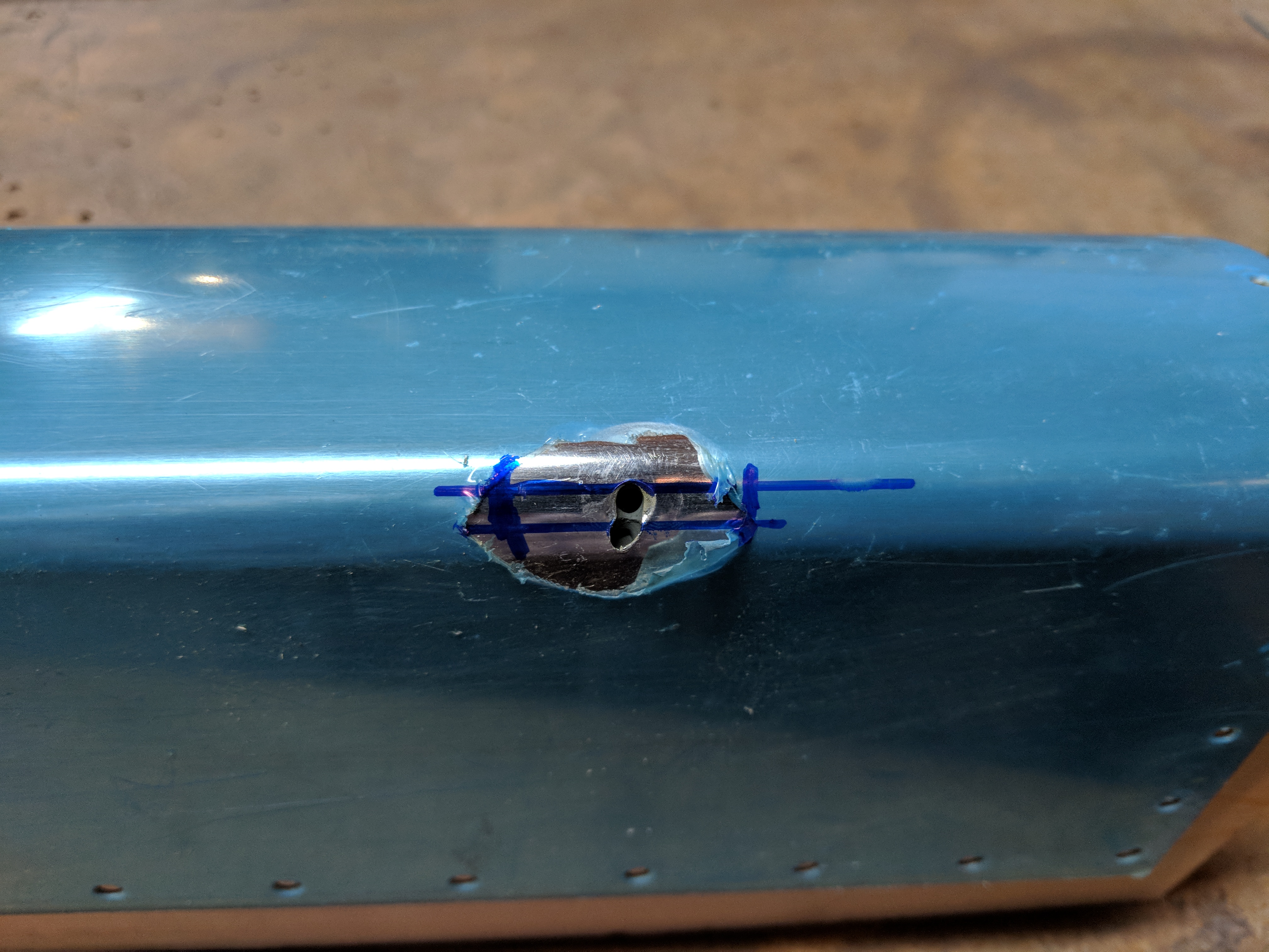
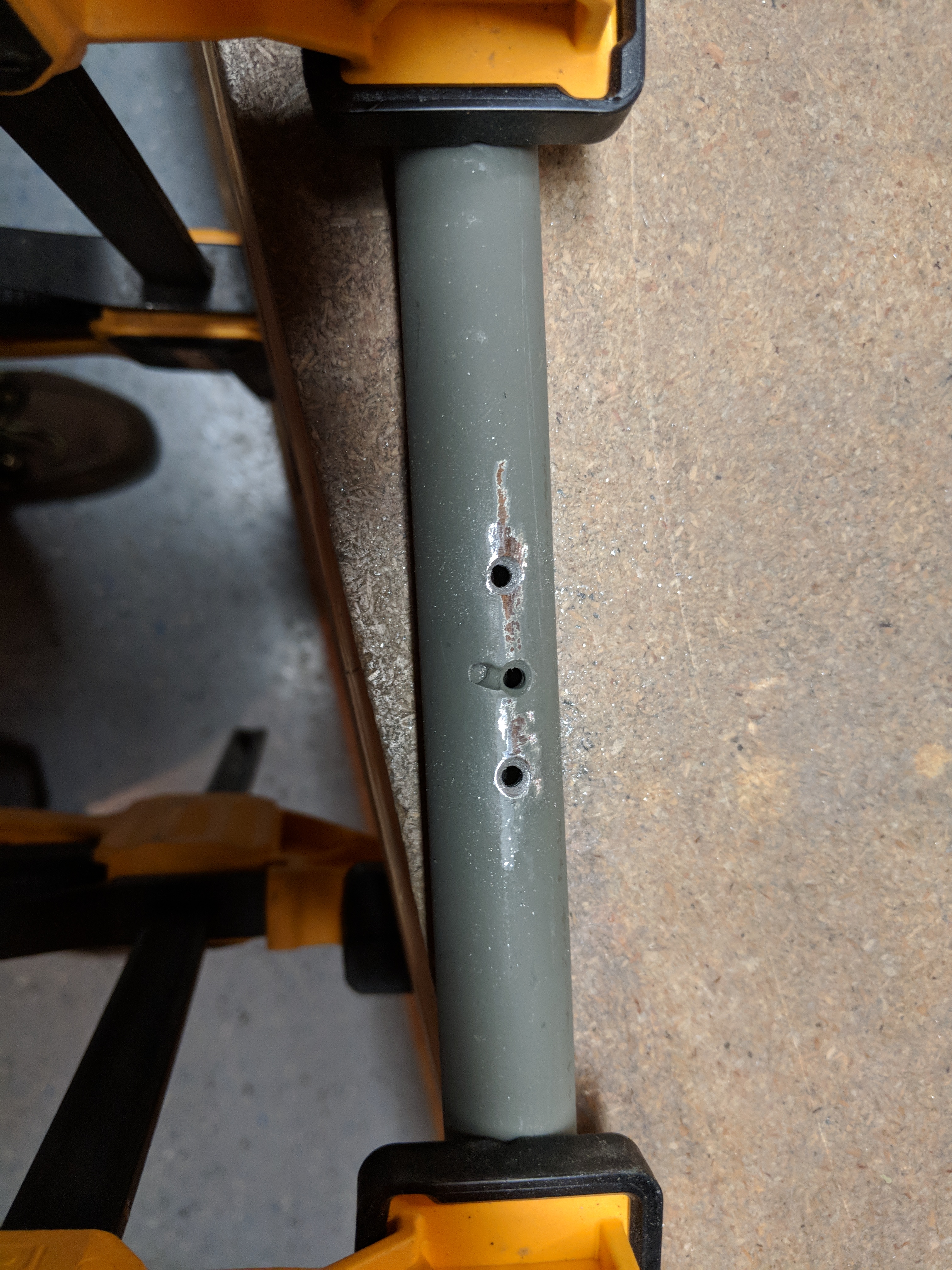
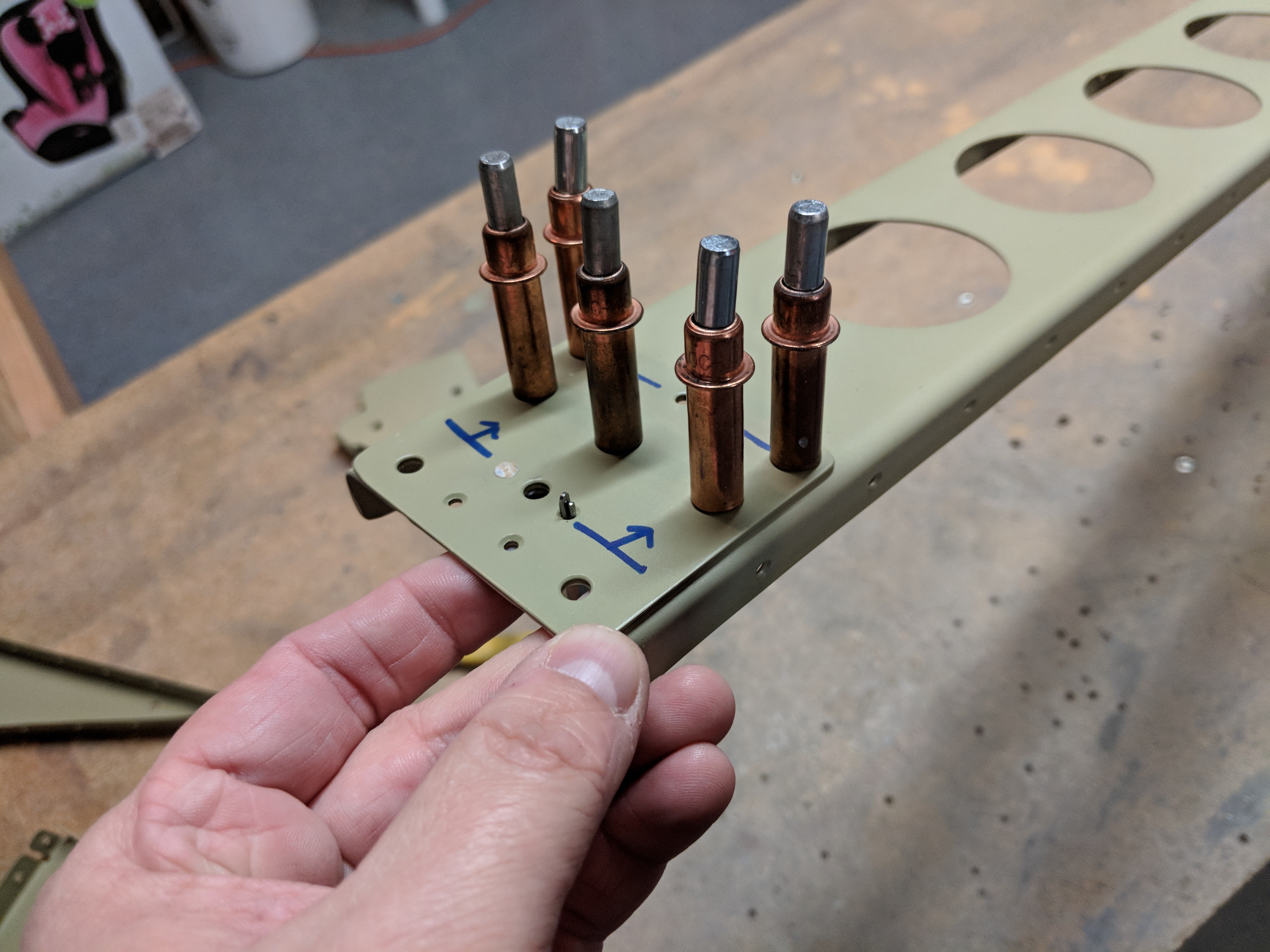
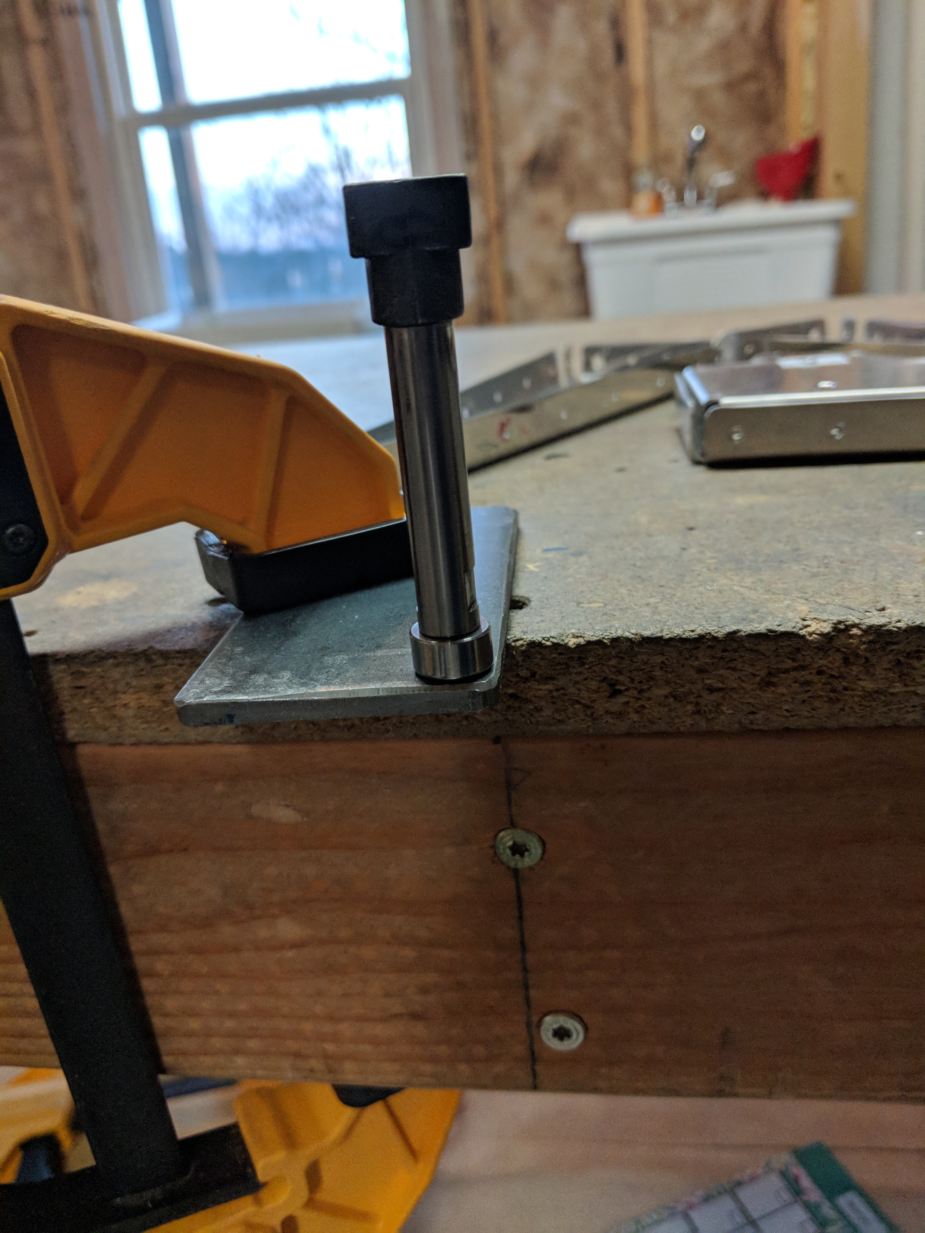
Once I had the new holes drilled to a #30, it was time to enlarge the holes to their final size.  I used a uni-bit (step drill) to enlarge the holes.  I first started out by drilling the 3/4″ hole, using some spare wood blocks to hold the rib above my work bench to give the unit-but room to do its job.  I went ahead and drilled all the ribs 3/4″ conduit hole since it wont interfere with any other build steps.  I even did the inboard and outboard ribs.

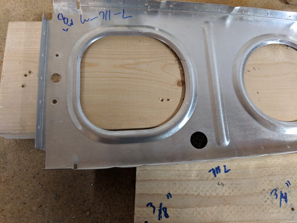
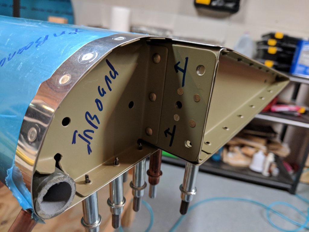
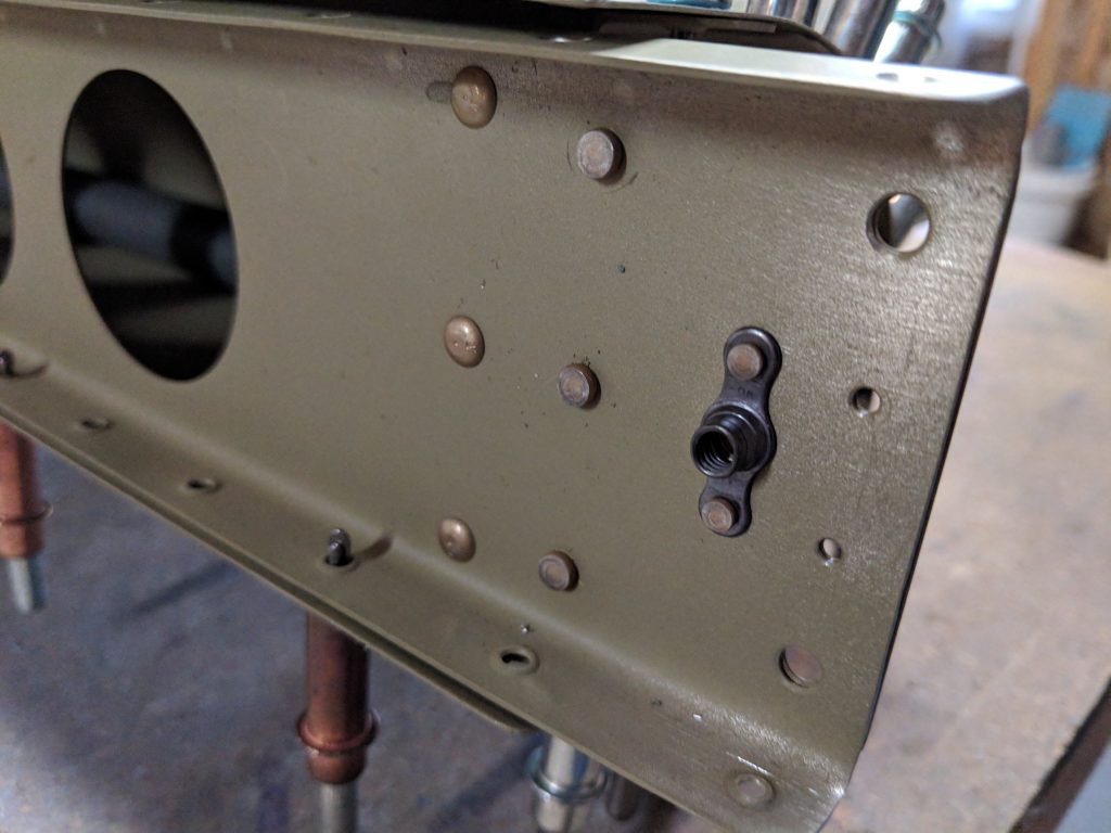
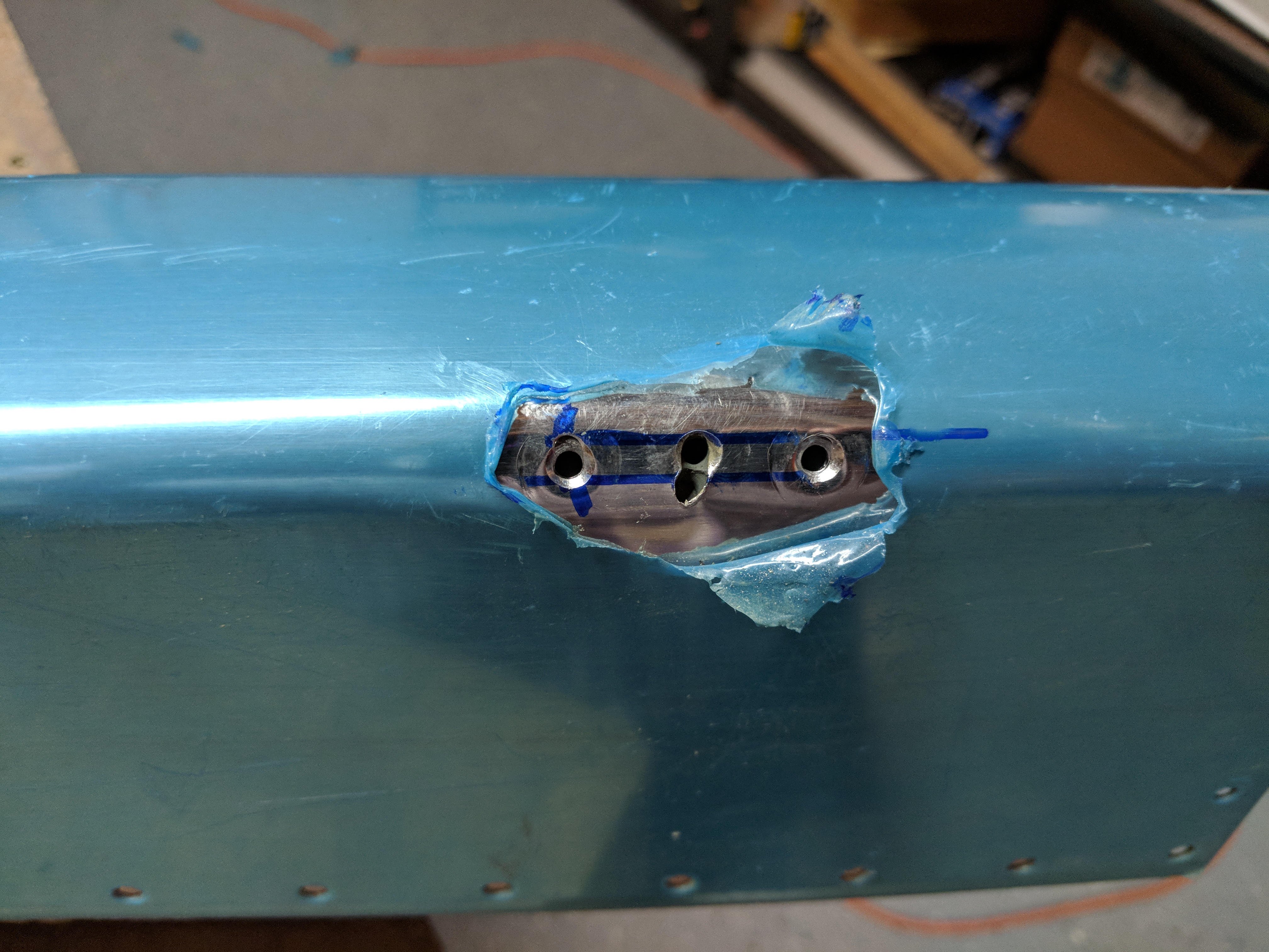
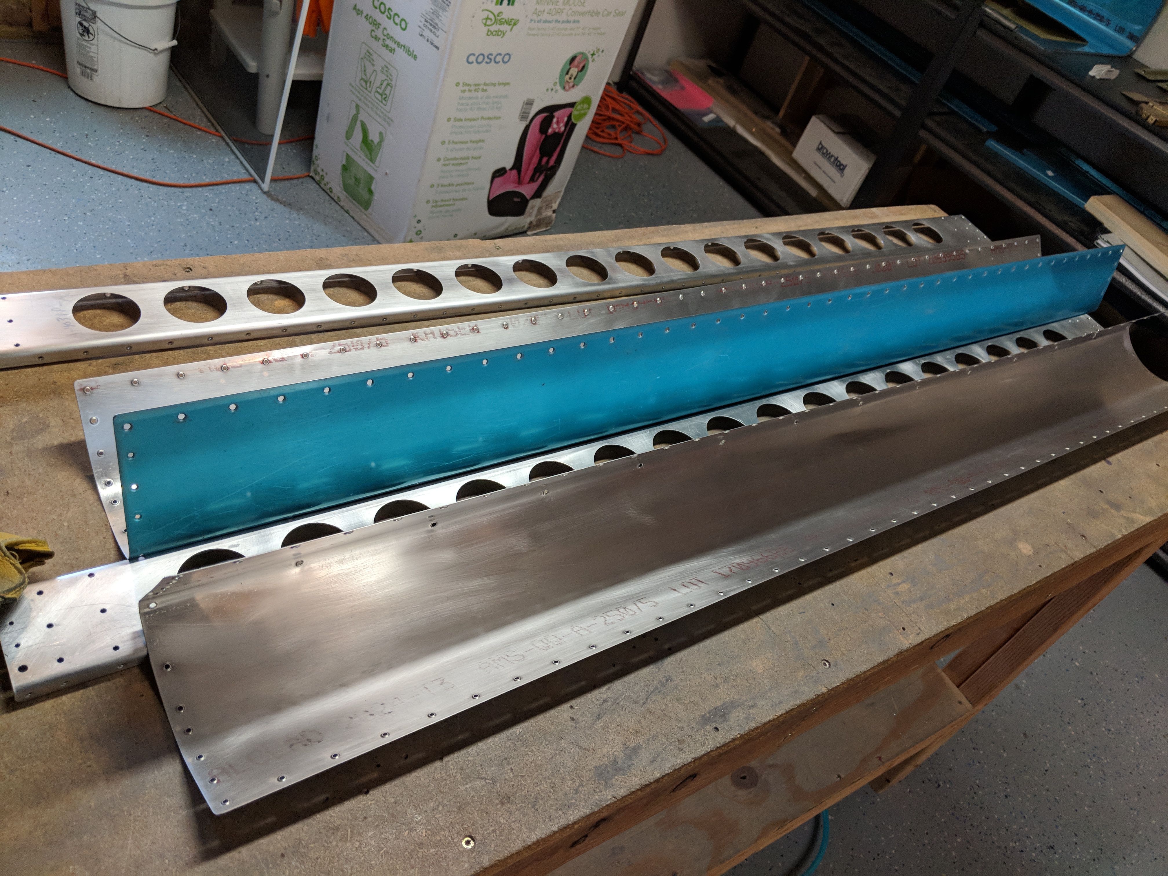
Then I enlarged the new 3/8″ hole on all the ribs, including the outboard ribs. BUT, I did not enlarge the existing tool holes on the outer and inner most ribs since they are used for aileron alignment. I’ll leave these for the very very last once I have the control surfaces aligned and mounted.  Here’s what the holes look like once they are all drilled and enlarged to size.

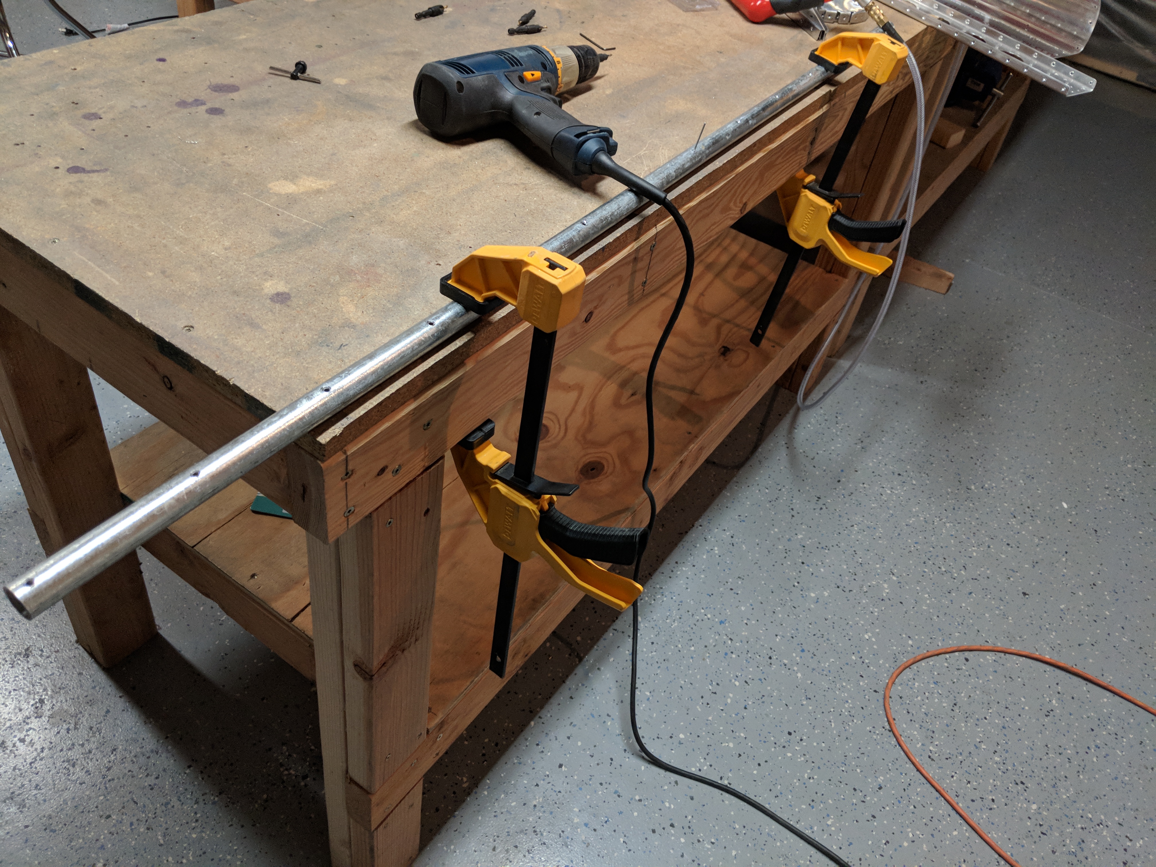
After I had all the holes done, I decided to call it a night.  I need to deburr all the holes, but I may leave that as a job for when I deburr all the other holes. The next thing I HAVE to get done is build my wing stand, since it is now the critical path in my build. Heres all the photos from tonights build:

Google Photos Link: https://photos.app.goo.gl/MrcQXdzN83ZGRWKU2

Hours Worked: 2.5

Finishing the Right Aileron

Not much to report tonight.  I spent about 45 minutes riveting the bottom of the right aileron.  All I had left to do was squeeze a few rivets on the ribs and then pull the blind rivets where the skins meet the spar.  It starts by putting the aileron, bottom facing up, on my flattest work bench, and then weighing it down to ensure it stays aligned, and not twisted.

I found that the center section is just about perfect, and I added a little more weight with my cleco bucket. Once it was weighed down, and I had checked the flatness, I set the blind rivets along where the counterbalance pipe is attached to the leading edge skin, checking the aileron for twist and aligment every few rivets. Next up I squeezed the last few rivets; first along the leading edge skin, and then along the trailing edge.

Once that was done, all that was left was to set blind rivets that join the top and bottom skins to the spar.  The pneumatic rivet puller I bought makes this easy and quick…. $25 well spent. The Right aileron is now finished and is on the shelf. Like the left one, I did not attach the mounting brackets just yet.  I’ll leave them off until I get ready to mount the aileron to prevent damage to other parts.  At this point, I am ready to move on to something else in the build.  I was going to dive into the tanks, but I need the wings on the stands in order to fabricate the mounting brackets.  SO, I guess I will jump back to the ribs, and finish them up and build my wing stands. I need to order some conduit, and some reamers. I need the conduit so I can drill our the holes in the ribs for it to go through. Time to spend some money I guess!

Hours worked: .75

Riveting the Right Aileron

This work session is the exact same as riveting the left aileron. So I won’t go into much detail.  Feel free to browse on over to my blog entry for the left aileron here as well as here  to get all the details. It starts out by riveting the nose ribs to the counterbalance pipe and then fitting that assembly into the leading edge skins, and attaching the spar.

Once that is all done,  I riveted on the nose ribs to the spar, and then fitted the assembly into my holding station to make riveting the top row of rivets easier.

Once I had the trailing edge skin clecoed into the spar/leading edge assembly, I make sure everything was in alignment and then began bucking rivets on the top of the spar/skins.  I am finding it easier to buck rivets with a gun, and am pretty happy with the results….most of the time.

Using an edge forming tool to break the edges of the leading edge skin really makes for a very nice and flush lap joint on these two skins:

The next step was to rivet the top half of the nose ribs to the leading edge skin and then insert the end ribs.

Then, Vans has us rivet the top half of the trailing edge skin to the end ribs, making sure to use the AN426AD3-4 rivet where the skins, ribs and spar come together.  All the other rivets are the regular AN425AD3-3.5.  I used my squeezer to set these rib rivets since they are easy to get to.

Once I had all the top half of the aileron riveted, the only thing left was to weight it down and rivet up the bottom half. I decided to end it there for tonight.  Was getting a little tired, and it’s never good to do final riveting when you’re tired.  I’ll set the aileron up on my flattest bench, weigh it down and rivet the bottom rivets another time.  Here’s all the photos from tonights work:

Google Photos Link: https://photos.app.goo.gl/1aBHUP8seEW2Zujw2

Hours Worked: 2.25

Finishing Riveting the Left Aileron

I ended up scoring a decent little pneumatic rivet puller / gun from Harbor Freight for $25 after the coupon during their sale.  This will save me some labor on ALL those blind rivets along the bottom of the ailerons.  Lets put it to use! I don’t like very much work on finishing the left aileron, so I jumped in right where I left off last night and scavenged around to find some sort of weight to hold the aileron down on my flattest work bench. My first attempt wasn’t satisfactory:

So, I ended up going with something a little more appropriate for aircraft work……the center section that comes in the wing kit 🙂

This thing worked out pretty great.  It’s heavy enough to hold the aileron flat, but not to heavy to damage, and its almost the length of the entire aileron.  I also cleceod every hole where a CS4-4 bling rivet would go to help hold it straight.  Next I used my rivet squeezer to squeeze the rivets on the bottom of the trailing edge skin, to attach to the nose rib.  Then moved on to squeezing the bottom rivets to the end ribs. That only leaves the blind rivets left.  I removed every other cleco, and staged a few CS4-4 blind rivets in the holes.

The first thing to rivet was the counterbalance pipe, and with the new tool, it was easy. I then started in the middle of the bottom skin rivets and then worked my way out from the center to the ends of the aileron, using the new pneumatic rivet puller to do the work.  After a little adjusting, the rivet puller was working really well, and setting the rivets, and snapping the stems in one shot.  Like the instructions mentions, every few rivets I would double check that the aileron is still laying flat. The CS4-4 blind rivets sit pretty nicely into their dimples:

I did have one mess up I had to correct. During squeezing one of the rivets, I let the squeezer bounce a little and it set the rivet a bit proud of the surface.  Too proud actually.  I ended up drilling it out, and re-riveting it.  Here’s the ugly bugger:

After a couple hours, I eventually wound up with a fully riveted left aileron! I decided to leave the mounting brackets off for now, since these were going on the shelf for a while.  I didn’t want the protruding brackets to ding or dent other parts of the aircraft as they sit on the shelf.  I will put them on once I get ready to mount the ailerons. Here’s me, holding the aileron:

Here’s all the photos from todays work:

Google Photos Link: https://photos.app.goo.gl/pmwqbM5bi7dmAhcl1

Hours Worked: 2.5

Riveting the Left Aileron

Time to start riveting up the ailerons! I gathered up the parts for the left aileron and studied over the drawings and instructions, and began final assembly and riveting on this guy.  We start out by riveting the A-704 nose ribs to the A-409 counterbalance pipe, and then slipping this assembly into the leading edge skin and cleocing it in place.

Once the assembly is in the leading edge, we go ahead and cleco on the spar, and then rivet the nose ribs to the spar, only.  This is because the rivets are hard to get to when the trailing skin attached. I put the shop heads on the rib side of the spar, because the metal is thinner there.

Once the nose ribs are riveted to the spar, we go ahead and slip the trailing edge skin under the leading edge skin and cleco it to the spar. This took a little fiddling around, and in between the process of taking photos and fitting the skin, I went ahead and removed the blue plastic, since it was getting close to time to rivet.

I also got a little creative. I had seen a few builders make a quick little holding jig for the aileron so you can attach it firmly to the bench, which makes it MUCH easier to rivet.  It’s as simple as cutting 6″ lengths of 2×4 and screwing them down to your bench.  I then took some spare brass fittings and some drywall screws to make fasteners for the aileron, and screwed it down to the 2×4’s using the mounting bracket holes in the spar.

The photo below shows how I used some scrap brass plumbing fittings to serve as “soft bushings” to keep the drywall screws from damaging my spar. They also help to distribute the light load more evenly.  These are only just tight enough to keep the aileron from wiggling about while I am riveting on it.

This made it SOOO much easier to rivet.  Vans has us rivet the TOP of the skins to the spar first, using the opening between the skins on the bottom as easier access. Essentially, my aileron is held upright so I can reach around with my left hand and hold the bucking bar inside the skin (reaching in from the unfastened bottom of the skins), and shoot the rivet on the top of the spar.  After a little bit, I eventually had the top riveted and looking good.

Next was to rivet the nose ribs to the leading edge skin, but ONLY the top half of the skin gets riveted for now.  Leaving the bottom loose to make access easier.  I used my squeezer to set these rivets extra carefully since they are on some complex curves. There is one odd ball rivet that is a tad longer than the other AN426AD3-3.5, its an AN426AD3-4, and the plans marks where it goes….right in the corner where the rib mets the spar and skins.  After the nose ribs were halfway done, we move on to inserting the end ribs and riveting ONLY the top half of those guys on each end.  Again, i was able to use my squeezer to get nicely set rivets here. Vans also has us go ahead and rivet the end ribs to the spar with their flush rivets.  The other holes are the bolt holes for the mounts.

Having successfully riveted the top half of the aileron, I decided to call it quits for the night.  Harbor Freight is having an Easter sale tomorrow, and I think I will pick up a cheap pneumatic riveter to set all those blind rivets on the bottom of the aileron.  This is a good point to stop, because I can’t do much more until I get that blind riveter. Here’s all the photos from tonights work:

Google Photos Link: https://photos.app.goo.gl/EpWrbJFTwoDX8DxU2

Hours Worked: 3.5

Priming the Counterbalance and Fixing the Mistake

Even a little progress is some progress.. right?  I didn’t get a whole lot done tonight, but I did get over a small hump that I have been mulling over:  The messed up leading edge rivet.  A few posts back  I ended up damaging the left leading edge skin due to some poor drilling technique.  After conferring with several folks, the consensus was to drill two new holes of the same size, 1/2″ on either side of the bad hole.  So, I clecoe’d the A-409 counterbalance pipe back to its leading edge skin, and marked my holes 1/2″ on each side:

With that done, I used a center punch to help create a guide in the skin, then I SLOWLY drilled through the skin and into the pipe, being absolutely positive to control the drill so as to not repeat the same mistake.  Thankfully, the new holes were nice and clean and did’t wallow out like the earlier one. The only thing left to do was to deburr the new holes, clean up the old janky one and then countersink and dimple the new holes.  I drug out the old, worn countersink and used it on the new holes.  Like the last time, I had to clean the edges with a file, and drill with a #30 to clean up from this old worn out countersink.  I’ll respray these spots with primer, so no biggie.

The last step was to dimple the leading edge skin to match the pipes countersinks, and I used the hammer/anvil method from my previous posts to get the skin to match the A-409 so the pulled rivet will sit flush.

All in all, I am pretty pleased with this repair.  I will probably stick a rivet in the bad hole just to help cover the ugliness it leaves behind, and the other two holes will be what carries the load.  I decided to go ahead and prime the inside of the A-409 pipe tonight as well.  I made a trip out to Ace Hardware and picked up some 1/2 wooden dowel rod to use as a pusher, and also found some self-etching, rusty metal primer that came in a small can, perfect for pouring.  I figured I would roll up some pieces of scotchbrite pad so they fit tightly into the pipe and then shove them through a few times with the dowel rod.

The seems like it got a lot of the burrs from the holes, as well as scuffing the inside of the pipe decently enough, so the next step was to clean the insides.  I rolled up some paper towels in the same fashion, and soaked them in acetone and forced them through the pipe using the dowel several times, until the towels came out clean.  Lastly, it was time to pour in the primer.  I taped up all the holes, and then tapped up one end of the pipe, and poured the primer inside the pipe, using a good bit to ensure coverage.

Once I had a good bit of primer in the pipe, I tapped off the open end and slowly rolled the pipe, at an angle flipping it several times to ensure I fully covered the inside with the primer.  Then, I took the tape off, drained the excess into a little plastic dish and used it and a little fresh to do the same for the other pipe.  I ended up wasting a little, but not too bad.  This stuff was only $5 anyways, so no worries.  I left the pipes turned on end at an angle so the excess would drain onto a paper towel.

While they were in the booth, I went ahead and touched up the new holes with some spray self-etching primer, and then touched up any other spots that needed it.  They’ll sit in the booth to finish drying and then I will start riveting stuff together!  Thats it for tonight, and thats all the photos.

Google Photos Link: https://photos.app.goo.gl/PWpyrdFto2QB85iR2

Hours Worked: 1.25

Riveting Aileron Reinforcement Plates

I didn’t get much accomplished tonight.  What has gotten me stuck is just how to deburr the inside of the A-409 counterbalance pipe for the aileron leading edge.  But I did get a little progress made, I’ll detail that below.  I started out by pulling all the parts out of the booth, and wiping any overspray off them.  Then I marked the parts and reading over the instructions and plans.  I was going to attempt to get the entire right aileron almost fully done, but after looking over the counterbalance pipe, I decided to do as much as I could on the parts. right up to needing to work with the A-409.

I grabbed the A-408 reinforcement plates for the right aileron and clecoed them in their proper spots, checking the alignments. Then I clecoe’d on the K1000-3 nutplate into position.  I also marked which holes I needed to rivet, as some of these holes need to be left open for the ribs when we assemble the skeleton.


I set the small -3 rivets in the nutplate first, using my squeezer and checking each rivet.  Then I followed that up with the larger -4 AN470 rivets that attach the A-408 plate to the spar.

Once I had all the rivets set for the right aileron spar plates, I decided to go ahead and do the left. These went pretty quick, and didn’t require any complex work, and they came out nice since I was using the squeezer.

I put the shop head on the A-408 plate, Conventional wisdom says to put the shop head on the side with the thickest metal.  The spar and the reinforcement plate are pretty close in thickness, but with the plate being .040″ I figured it best to put the shop head on that side.  Plus, it will make inspecting the rivets much easier since this side is the outside of the aileron.

Once I had that done, I took a look at the A-409 counterbalance pipe.  I still haven’t deburred the inside and primed, so I was going to tackle that tonight.  The priming will be the easy part:  Mix up a couple ounces of AKZO, tape up the holes in the pipe and pour some in and roll it around. The deburring is where I am challenged.  I rumaged through the shop and my garage in hopes of finding a long, thin rod that I could poke down the tube and force some scotchbrite through, but no luck. The only wooden dowel or wire I had were either too big or too small.  I think I can pick up some smaller wooden dowel rod and put some sandpaper or scotchbrite on the end and twist it through the pipe deburring and scuffing the surface at the same time. I’ll visit Ace Hardware tomorrow after work and see what I can come up with.  Here’s all the photos from tonights work:

Google Photos Link: https://photos.app.goo.gl/pi6YAmc0WJbrjQ573

Hours Worked: 1.0

Priming the Aileron Parts

I’m back in town after being gone for almost a week, and finally getting to do a little work done on he airplane. In the last session, I alodine’d some parts, so they’d be ready to prime when I got back.  I am still using the old method of scuffing and cleaning on larger parts, since I don’t want to get really messy with alumaprep and alodine, so I started out by scuffing the leading edge skins and the aileron spars and then getting them nice and clean with acetone. 

Then I mixed up 4 ounces of AKZO, and let it sit for the 30 minutes while I got everything ready for painting.  I moved all my parts into the booth, and then setup the ventilation system.

Finally, it was time to shoot a little primer.  The 4 ounces was just enough to cover all these parts very nicely, and left me a little over to touch up any missed or thin spots  I am really impressed with how well the Alodine parts absorb the primer, and how smooth of a finish it leaves.  I can really see why professional sprayers use this stuff for their exterior parts.  It makes a noobie like me come out with pretty decent primer jobs!

Since I had the ventilation setup, and everything ready for spraying, I decided to go ahead and get the galvanized pipe that’s used as the counterbalance primed as well.  Initially I was just going to leave it galvanized, since the galvanization process leaves it pretty corrosion proof.  BUT, I have been reading about corrosion between two different metals and decided to prime these as well.  I scuffed them up with some scotchbrite to get a good surface bite for the primer, and then cleaned them with acetone.  Instead of using AKZO, I decided to use some rattle can self-etching primer.  I am not sure how well a zinc-chromate epoxy primer would do on galvanized pipe, so I went with what I know works….plain old self-etching rattle can.

I haven’t gotten the inside of these things primed yet, I am still debating on how to best do that. I will probably end up using some scotchbrite on some string to scuff the inside, clean with acetone wash and then pour in some primer and roll it around to coat.  That finished up tonights work, I cleaned up all the mess and will let the parts sit overnight or longer to get a good cure before moving on to the next step. Here’s all the photos from tonights work:

Google Photos Link: https://photos.app.goo.gl/8m4XfPMInvp7JZhq2

Hours Worked: 2.0

Dimpling and Alodining the Aileron Parts

A LOT accomplished tonight.  I managed to get all the aileron parts dimpled, the counterbalance pipe countersunk, and even alodined a few of the small parts. I started off by setting up my DRDT-2 dimpler so I could make quick work of the skins.  This is pretty much what this dimpler is designed to do.  I also used it to dimple the holes in the spar, since its fairly thick metal, and fit in the DRDT-2 nicely.  I then used my squeezer to get to all the tight edges of the end ribs, and the very last little hole, I had to use my home-made hammer-and-anvil styled dimpler.  I made this a while back using some scrap metal, and a bent squeezer set.  I drilled a hole in the piece of metal, and countersunk it to fit a 3/32 dimple.  I just clamp it on my bench, and then use a 3/32 male dimple die to create the dimple in my parts.


I can get the small gap of the end ribs nicely over this hole and keep the flanges flat and straight, insert the male dimple die and the give it a good few whacks with a hammer and it forms a very nice little dimple.

After I had those end ribs done, the only thing that needing dimpling was the leading edge skins, where the counterbalance pipe is riveted on.  The instructions tell us to machine countersink the holes in the counterbalance pipe, and then when we use the bling rivets, they will form the skin into the countersunk holes enough to be flush.  I had seen other builders use different methods, but since my little hammer and anvil dimpler works so well, I figured I would give it a try.  First up was to countersink the pipe.  I ended up using an old cheap countersink I had bought from Home Depot years ago for other projects.  I didn’t want to ruin my nice one on this tough pipe, so I drug this one of the bin.

To get this done, I clamped the pipe down on to my workbench and went at it with my old electric drill and worn our countersink.  It worked good enough to get my countersinking done, but the holes were just nasty!! I had to use a #30 bit to clean up the holes and then file the outside edges down with a bastard file because of the roughness of the hole.

I ad to go back over them a few times, testing with a CS4-4 rivet as called for in the plans, to make sure I had the right depth.


Eventually I had them all finished up and cleaned.  Now, I decided to give something new a try.  I noticed that a 2×6 was just about the right height to hold the skin off the bench, but not quite thick enough to make it stable……HOWEVER…I realized I could use the bending brake I made with 2×6 boards to get the job done! I clecoe’d the counterbalance pipe to the skins, and then laid the skin over the bending brake and it worked great!.

Now, I could use my hammer and anvil dimpler set to create a nice dimple in the leading edge skins for the CS4-4 pulled rivet.


A few quick hits with the hammer and very nice little dimple was made in this rounded area!

You can see how well the rivet sits in the dimple now, and once I get it pulled, I believe I can use a small ball-peen hammer to round over the edges of the rivet to fit the countours of the leading edge on the ailerons.  I went ahead and did this to all the holes in both ailerons.  Now, all my parts were essentially ready for cleaning and primer.  I decided to go ahead and alodine my small parts since it’s easier to do that scuffing and cleaning, so I dunked them in a quick bath of alumaprep and alodine and rinsed them off.  They came out pretty decent!


I am headed out of town Sunday afternoon for a week, so I might be able to get these few parts primed this Saturday.  That will give them plenty of time to cure and be ready for final assembly and riveting when I get home next Friday.  That was a lot of work for one night, but I got a bunch accomplished.  Heres all the photos from tonights work:


Google Photos Link: https://photos.app.goo.gl/txFyiuYJP1s9RZ2u2

Hours Worked: 3.75

Deburring the Aileron Parts

Time to get down to the dirty work: Deburring, and edge finishing.  This will be a short post, but it was jam packed with work.  First I deburred all the holes in both aileron parts (skins, ribs, spar, etc).  Then, I deburred all the lightening holes in the spar, of which there are many.  I ended up using my Shaviv deburring tool to make easy work of all those lightening holes, and then touched it them up with a quick scuff of scotchbrite maroon pads. Next up was to deburr and smooth all the edges and corners of each part.  My bench grinder with a scotchbrite wheel helped this go quick. Then I had to manually work all the little tiny nooks and crannies that I couldn’t get with the wheel. The nose ribs were the worst! They are super thick metal, and have very complex curves, with some very tight spacing.  I ended up using a combination of emory cloth and maroon scotchbrite pads to get into all the tight spaces.  Eventually I had a bench like full of finished parts like this:

Lastly, it was time to do the same to the skins (leading edge and trailing edge for both ailerons). I deburred all the holes, and then used a fresh scotchbrite pad to smooth down and deburr the edges of the skins.  The last step I used a edge rolling tool to induce a very very slight bend in the last 1/4″ of the edge of the skins, downward.  This little bend will help make a very nice lap joint where the leading edge skin overlaps the trailing edge skins at the spar.  I only did this on the leading edge skin, since its the one that overlaps. This photo doesn’t do a very good job, but you can kinda see the little edge bend (Its bent slightly upward in this this pic):

And that wraps up the session for tonight.  I have all my aileron parts ready to go to the next step, which is dimpling and priming, and then final assembly/riveting.  I’ll get everything dimpled tomorrow night, and also put the small parts into alumaprep/alodine baths, and hopefully have everything ready to prime Saturday.  I have to head out of town for a week for business, so that will give the parts plenty of time for the AKZO to cure and be ready for riveting when I get home Friday. One last photo!

Google Photos Link: https://photos.app.goo.gl/KS0S5Zift06309g42

Hours Worked: 2.0