Assembling the Right Leading Edge

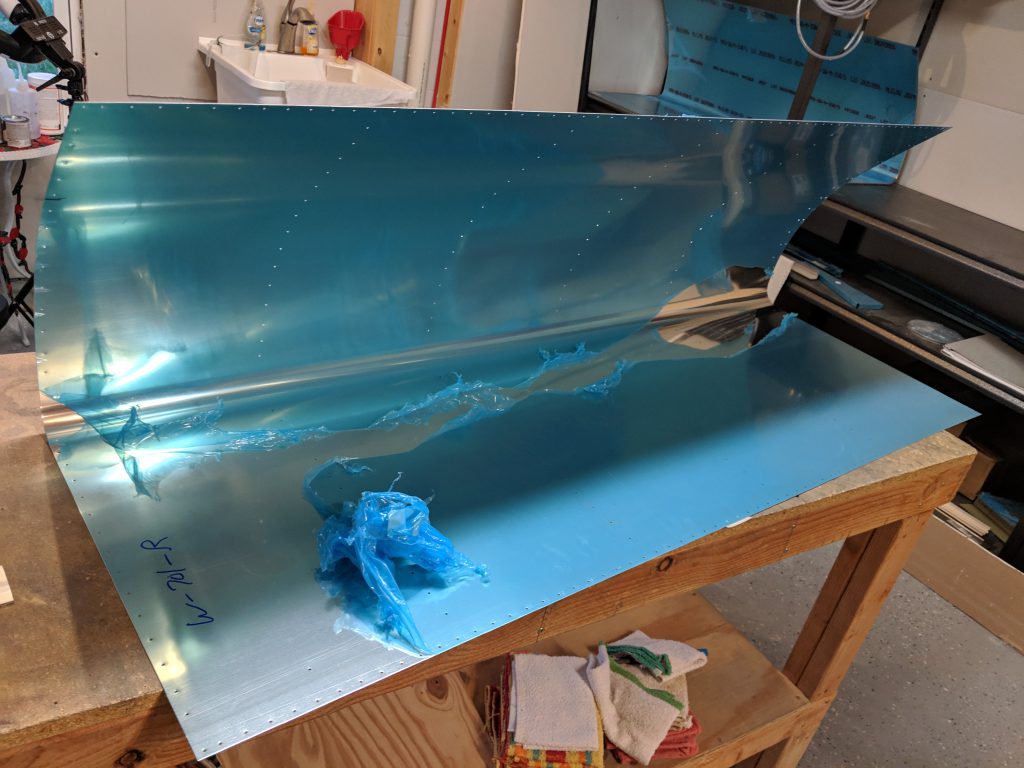
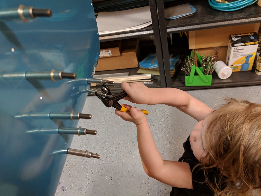
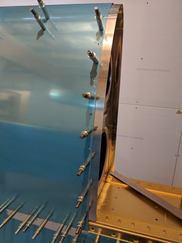
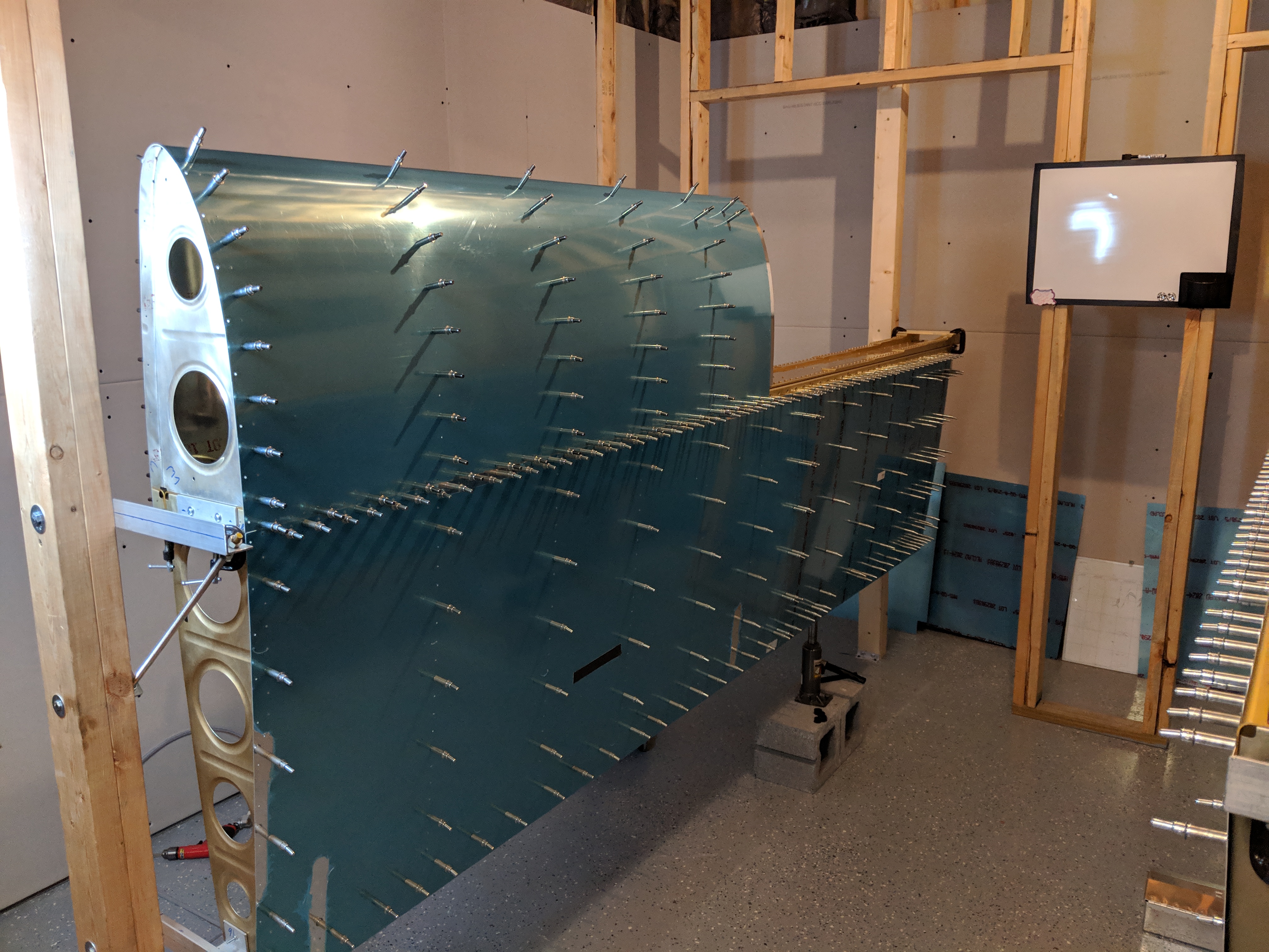
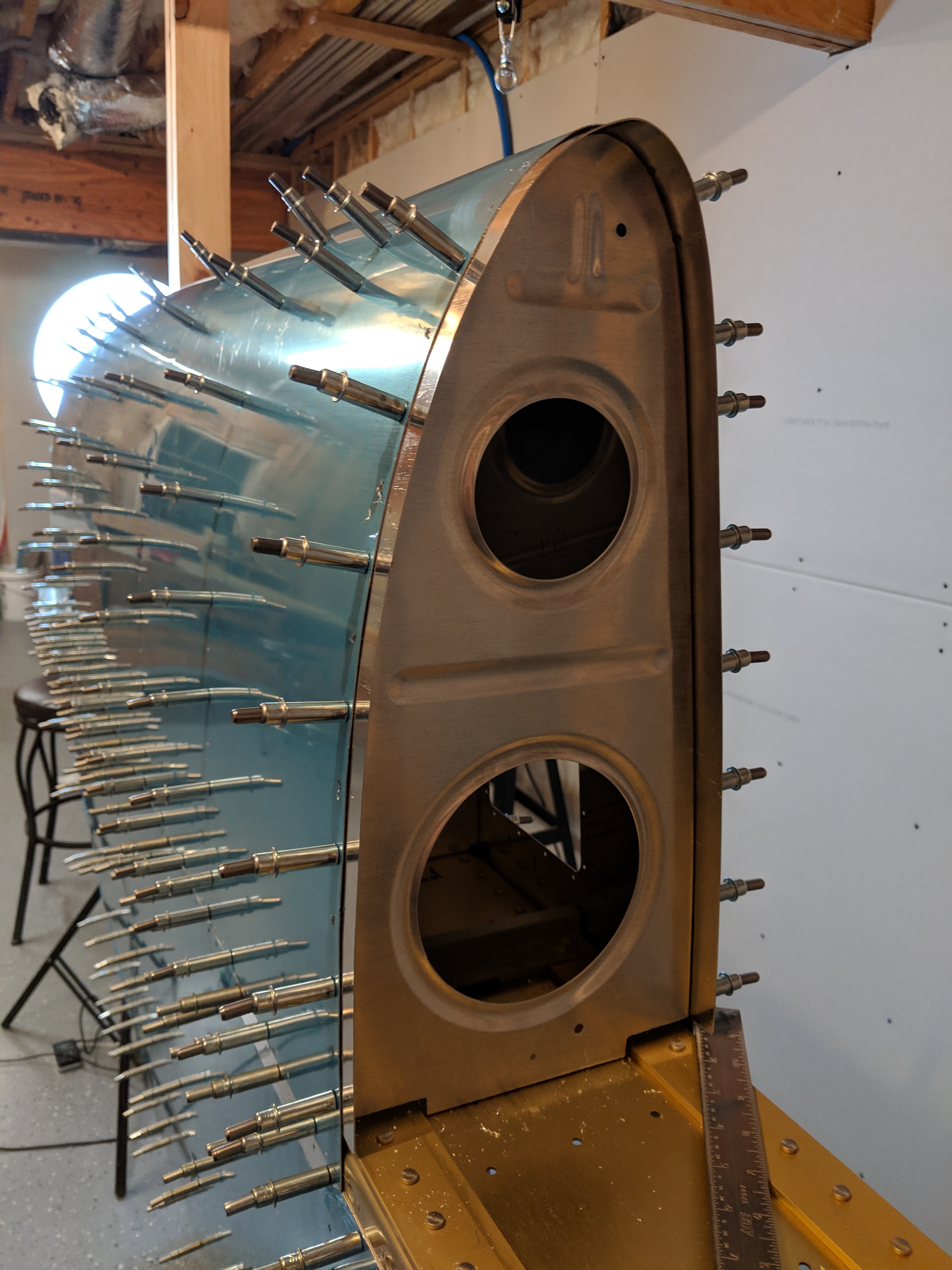
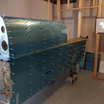
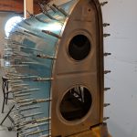
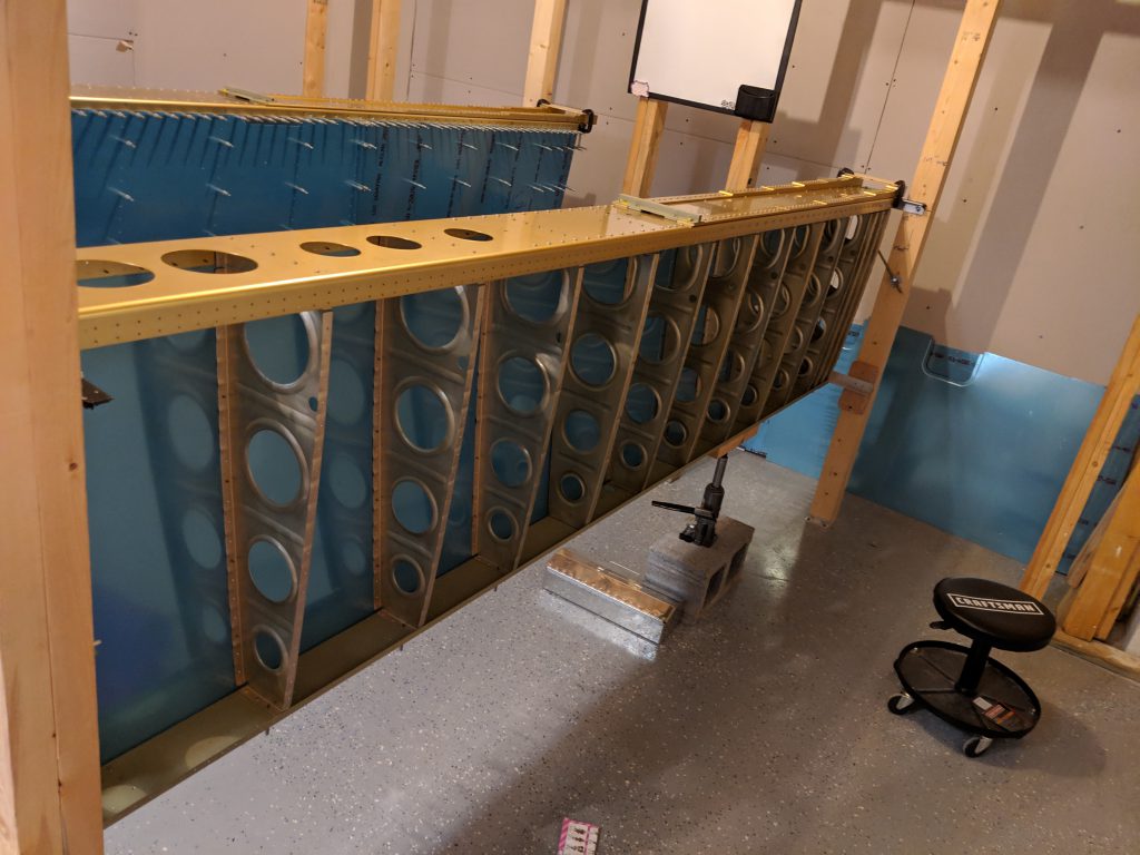
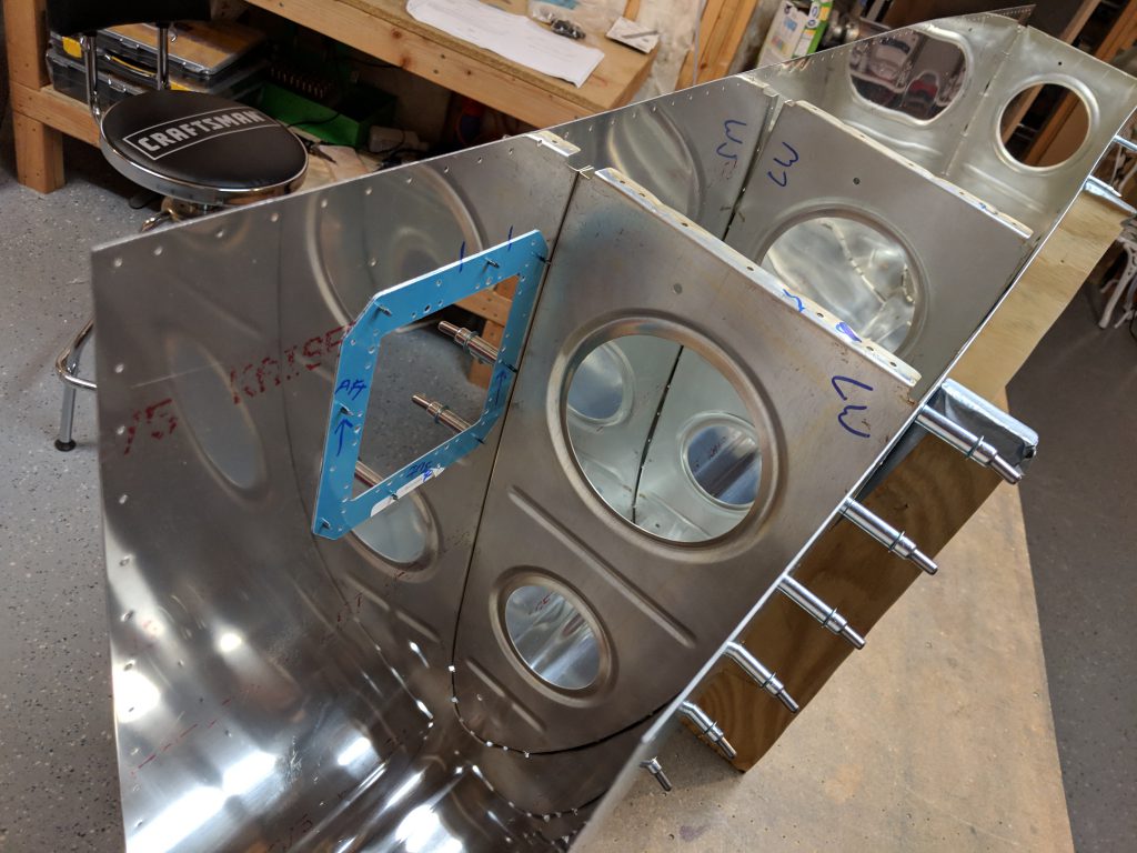
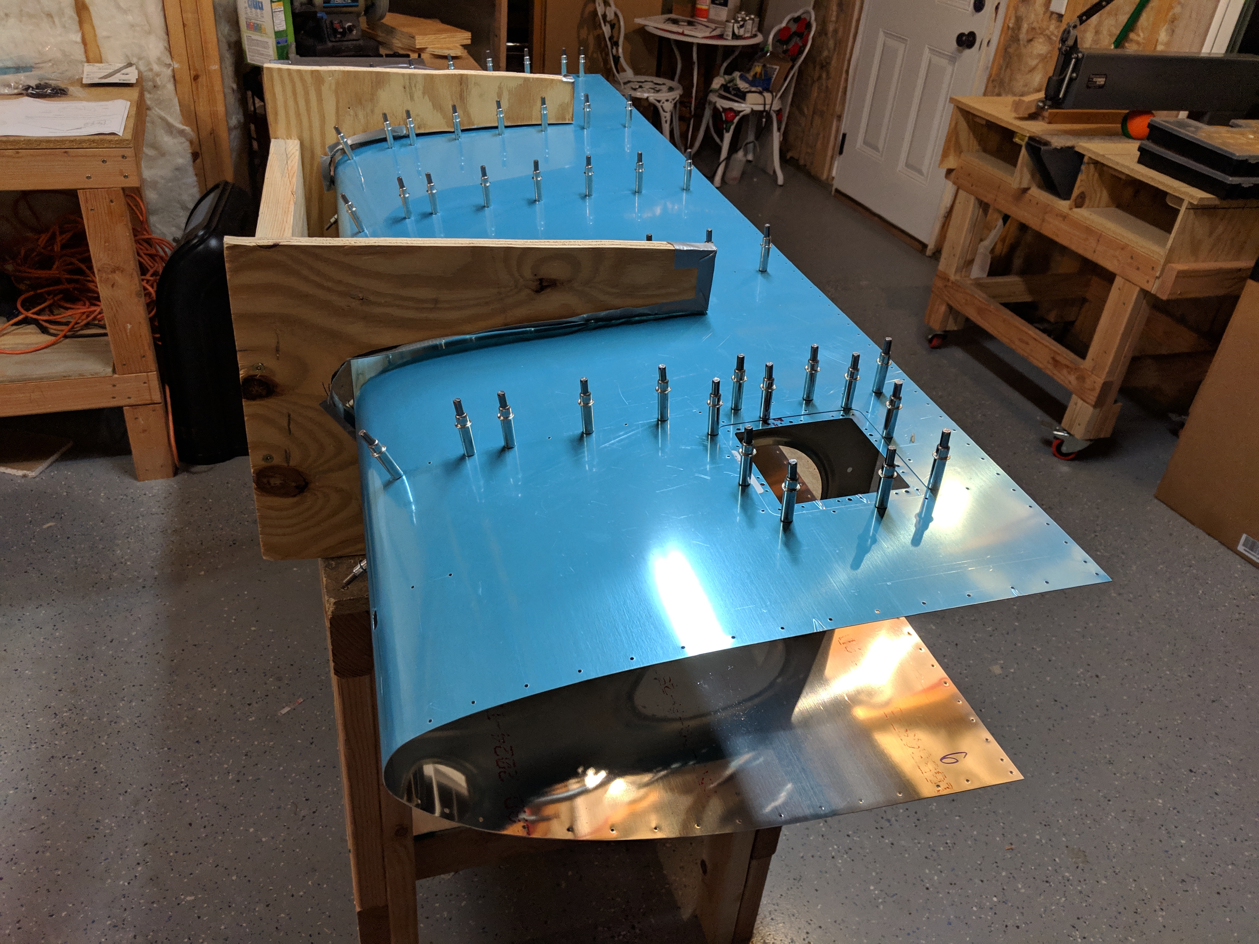
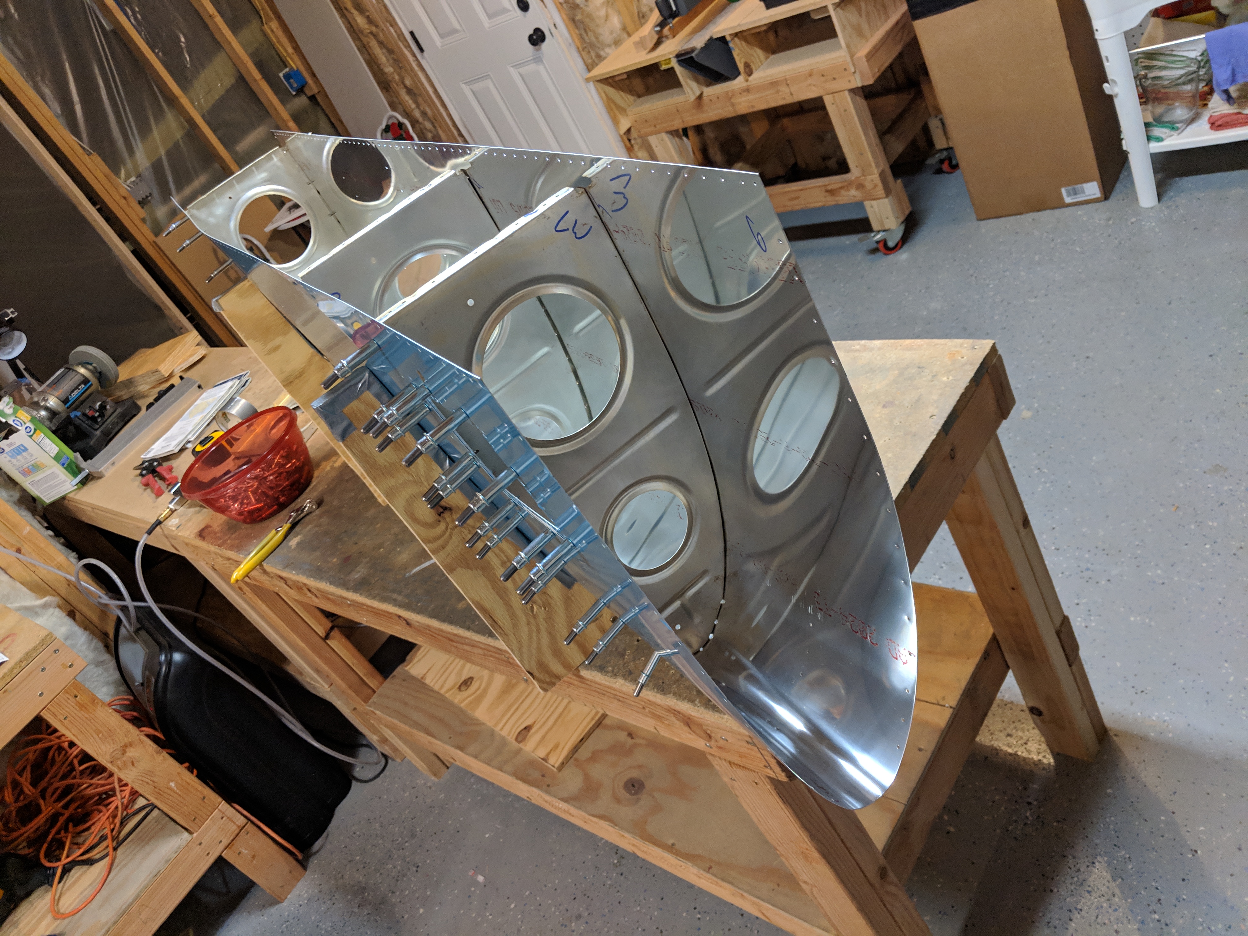
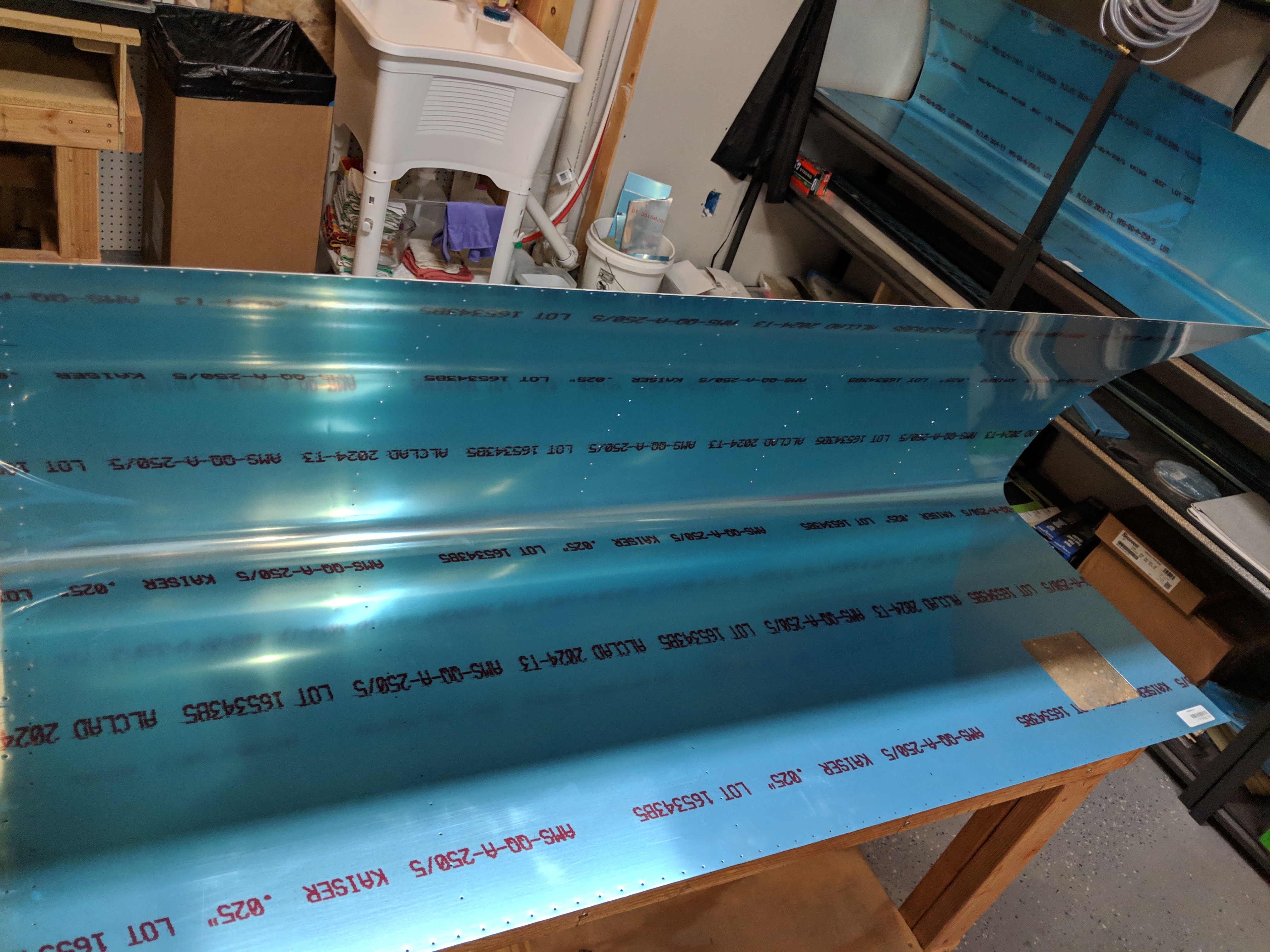
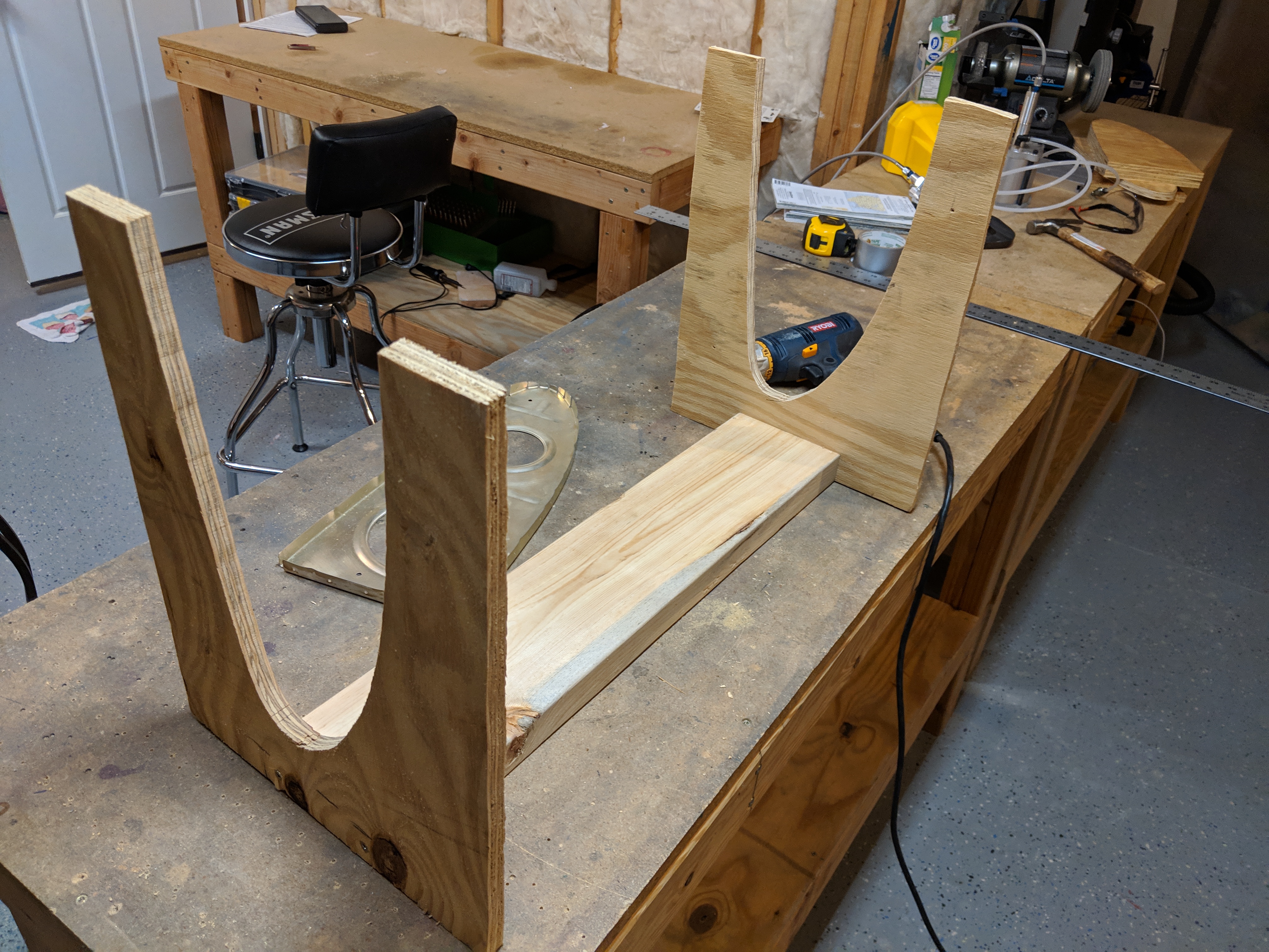
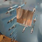
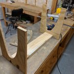
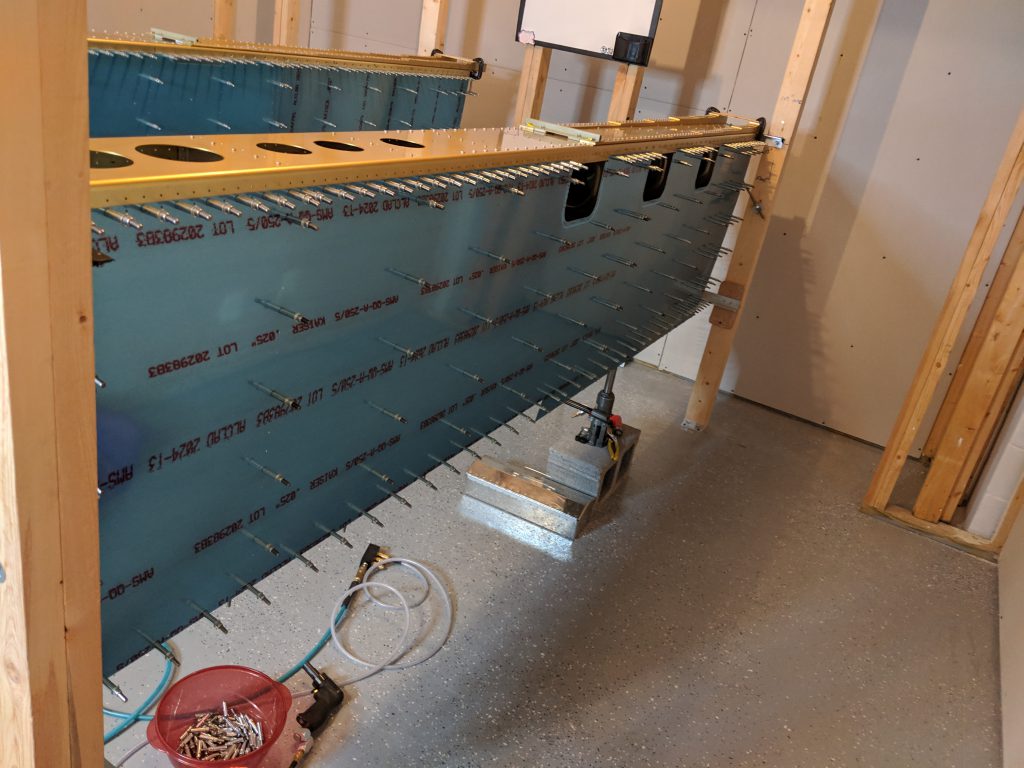
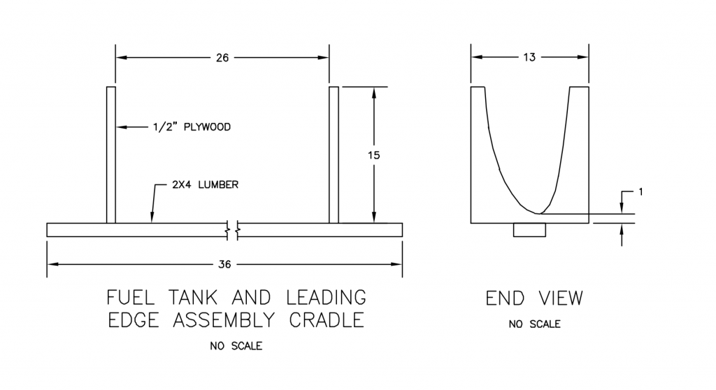
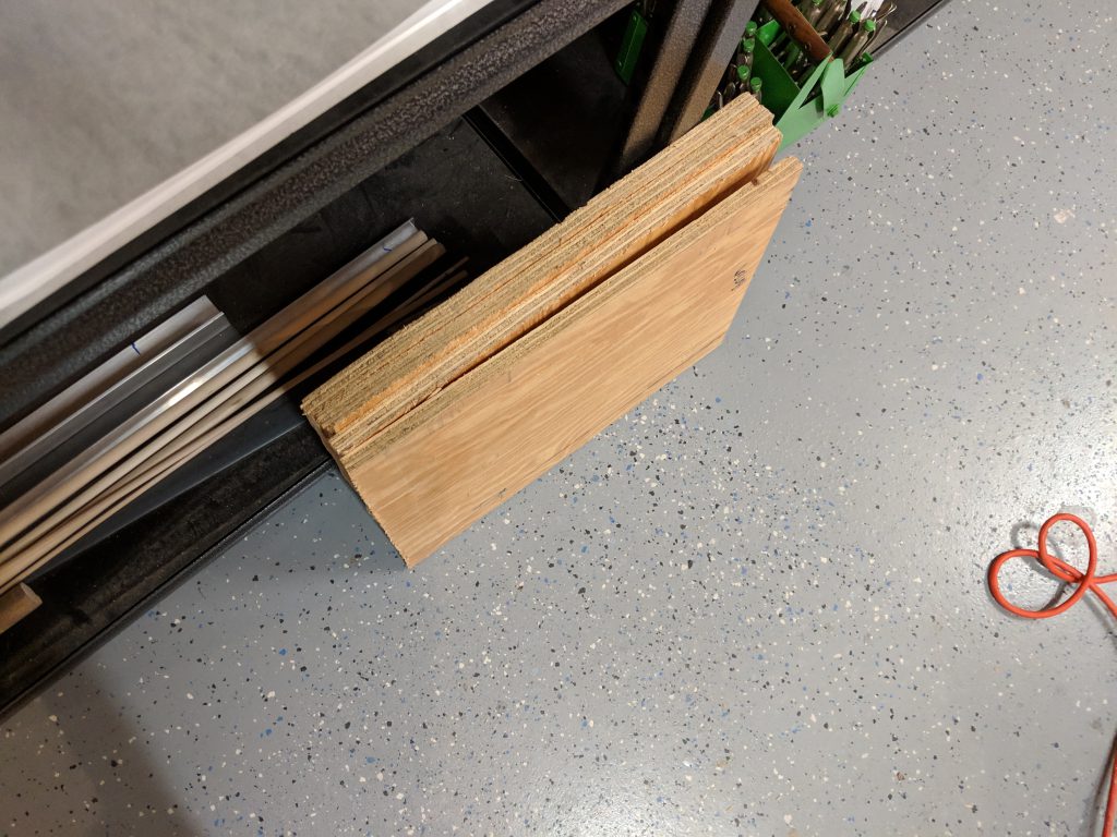
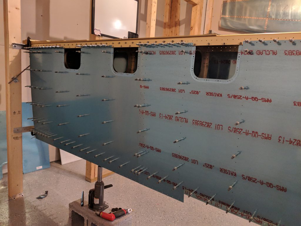
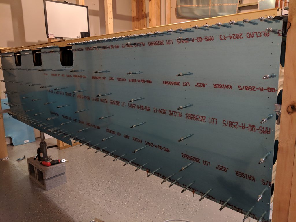
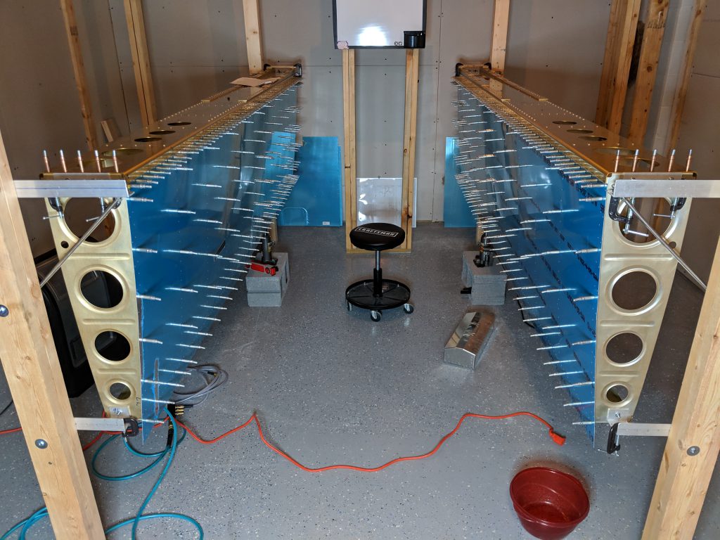
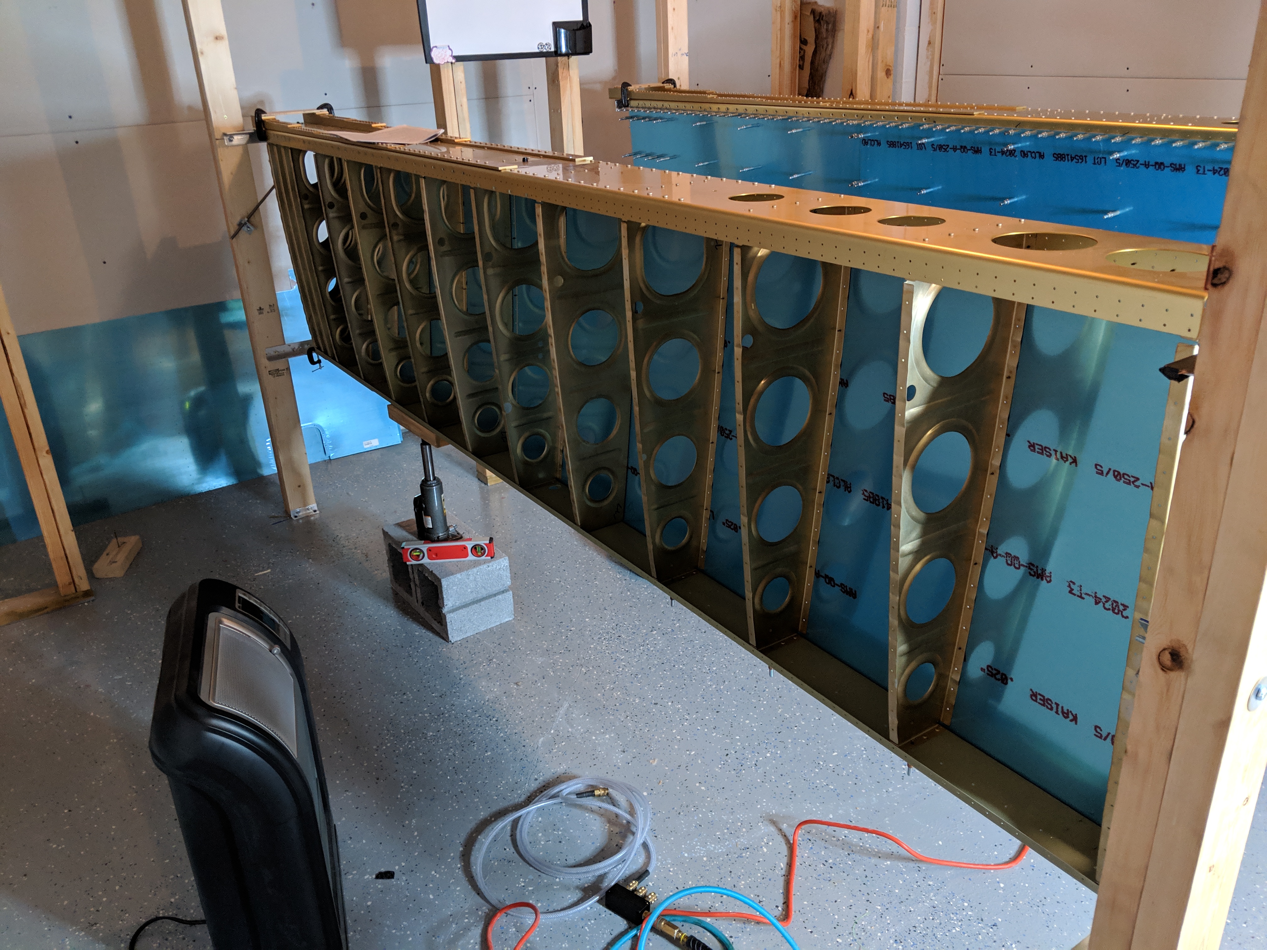
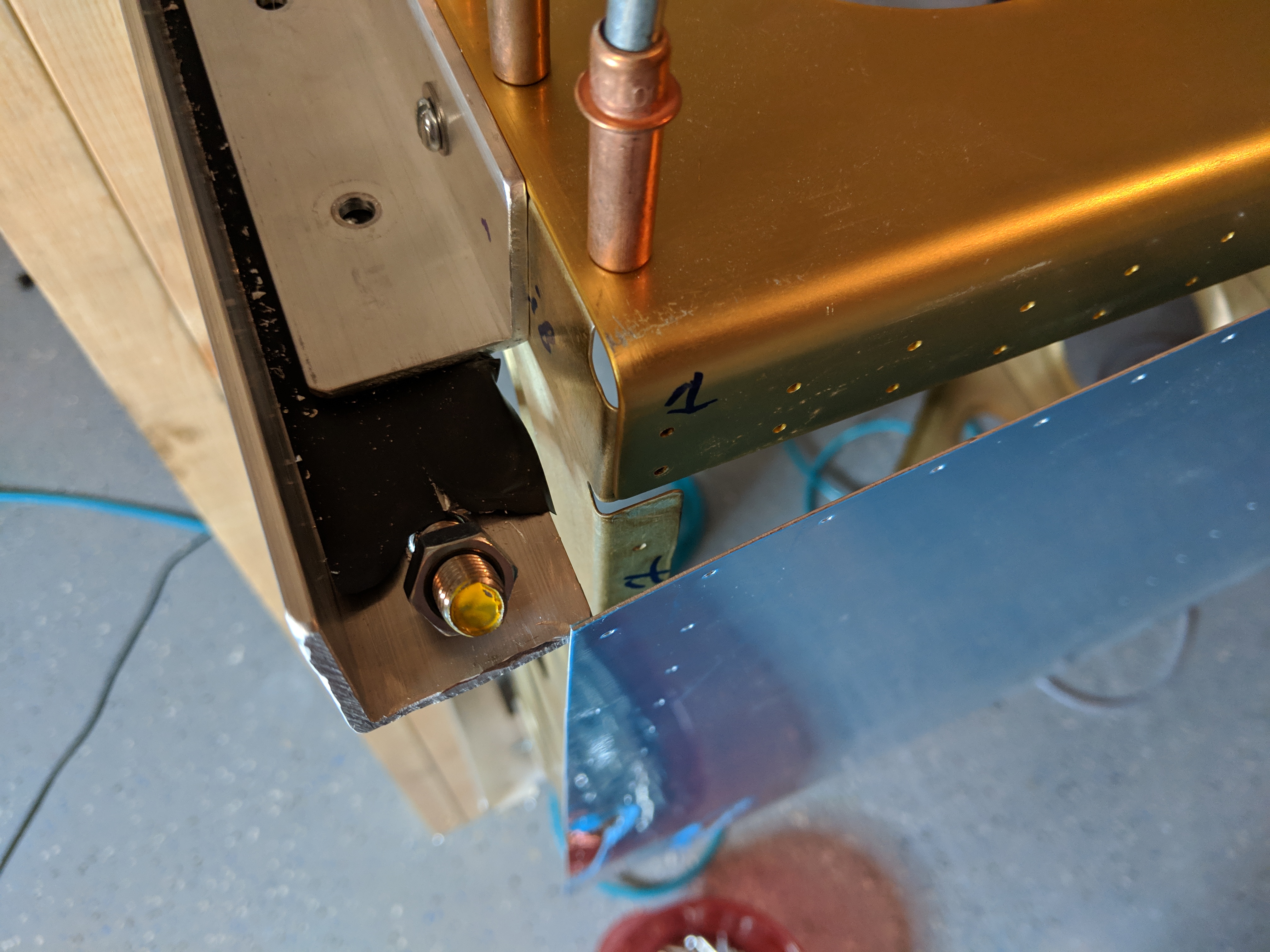
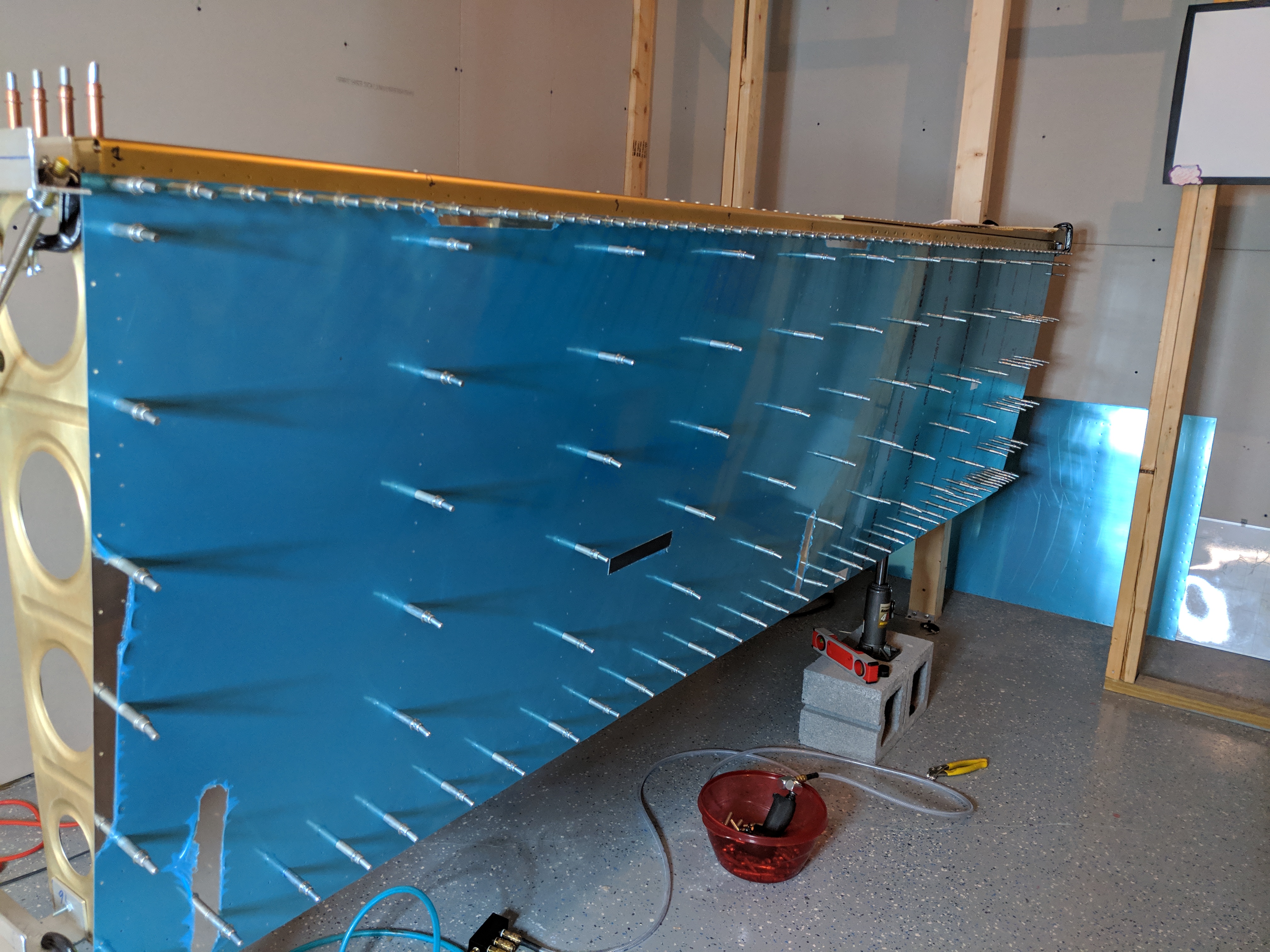
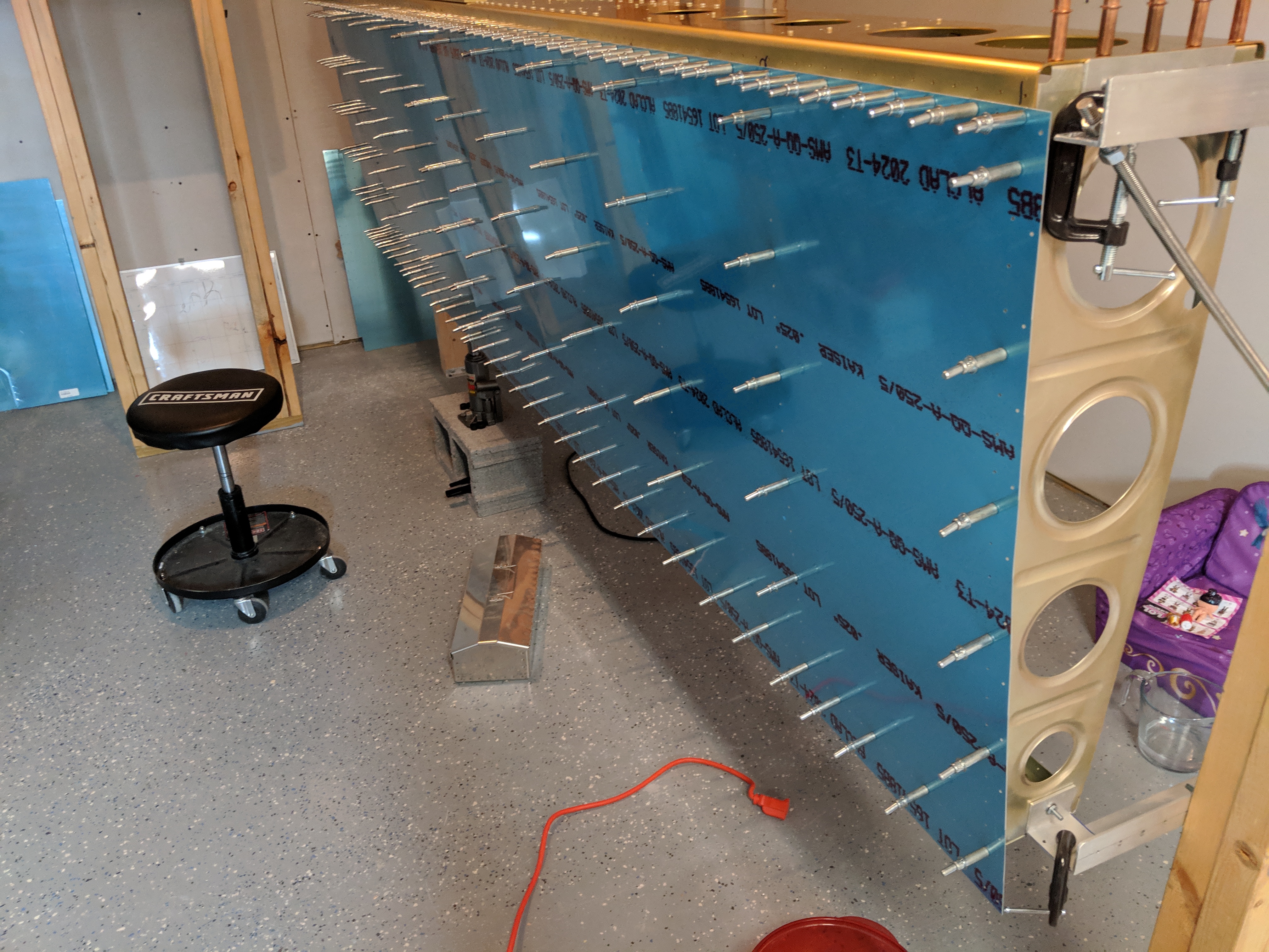
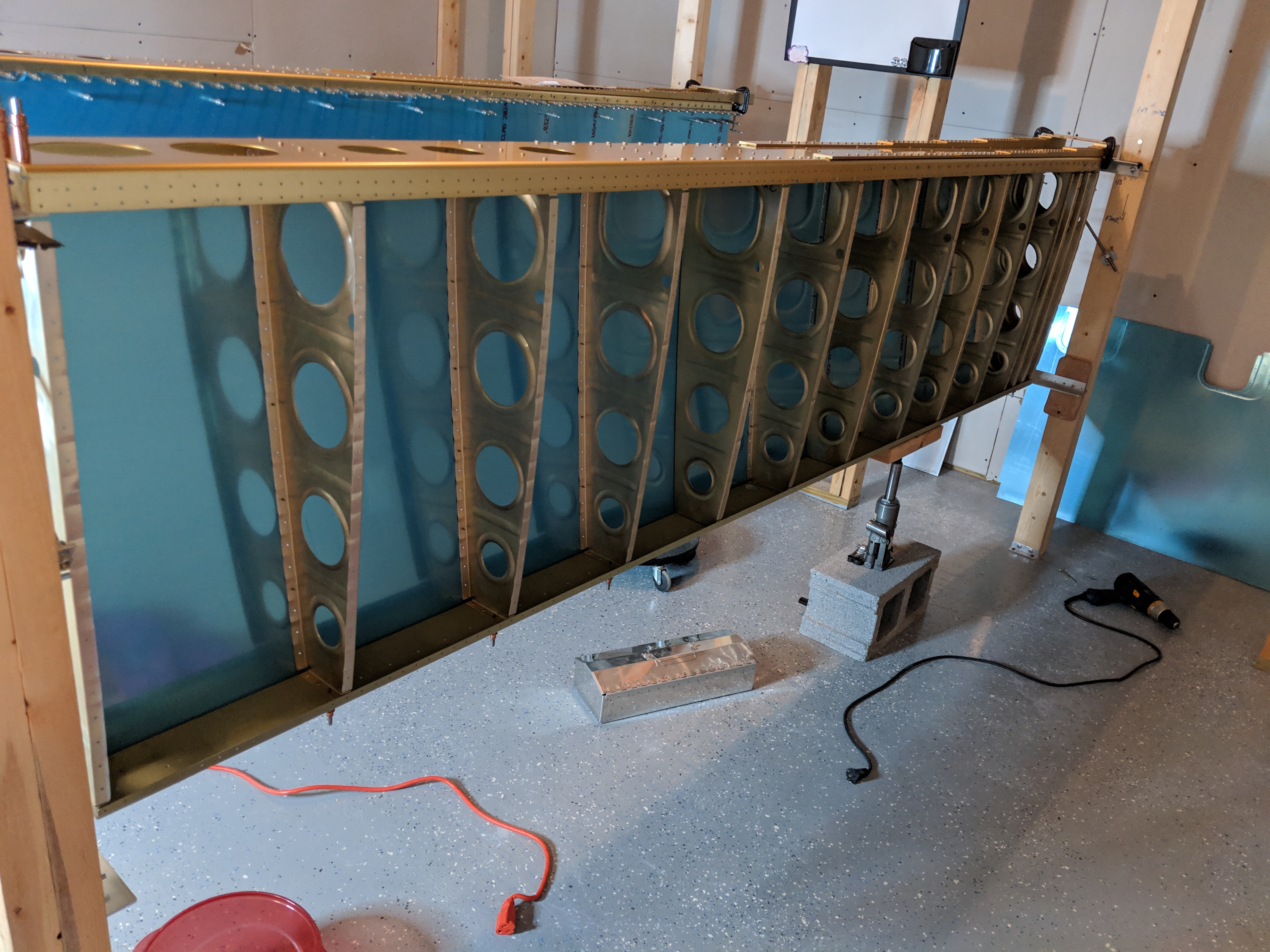
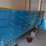
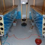
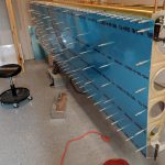
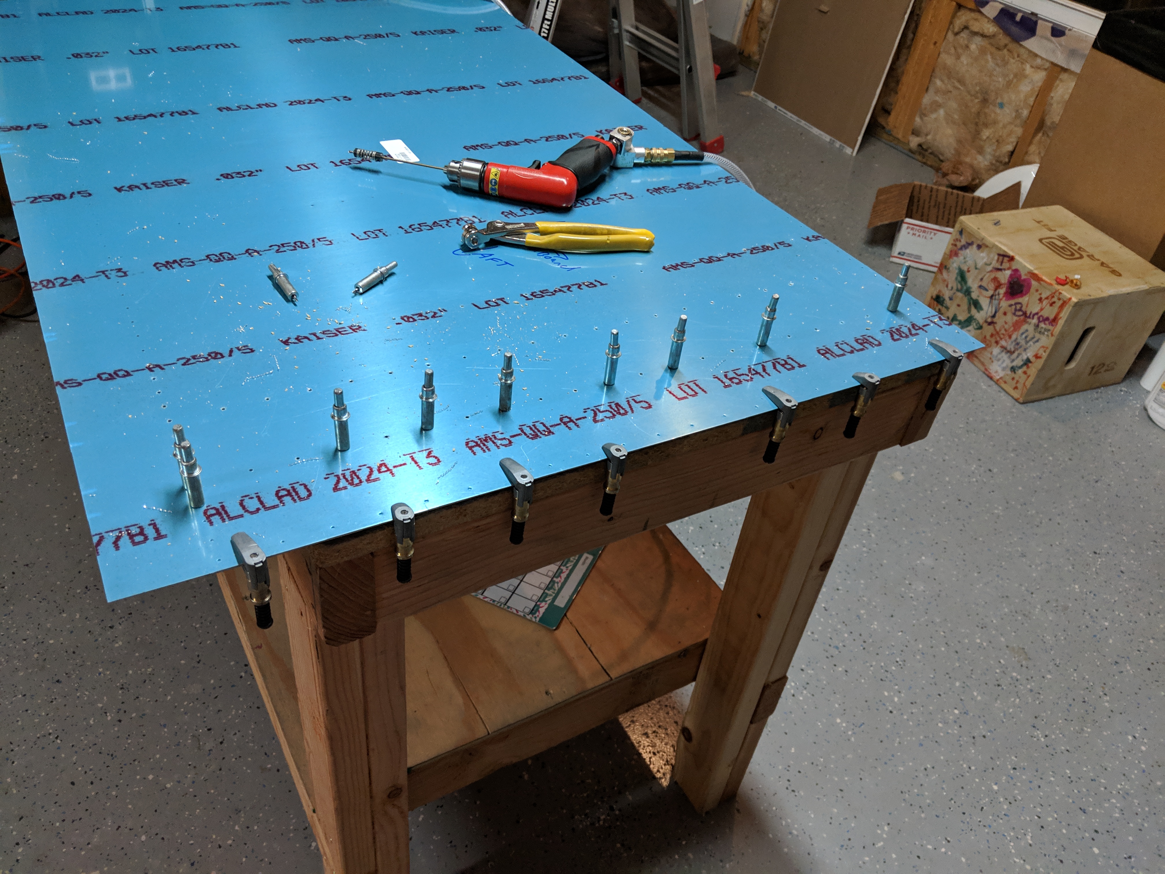
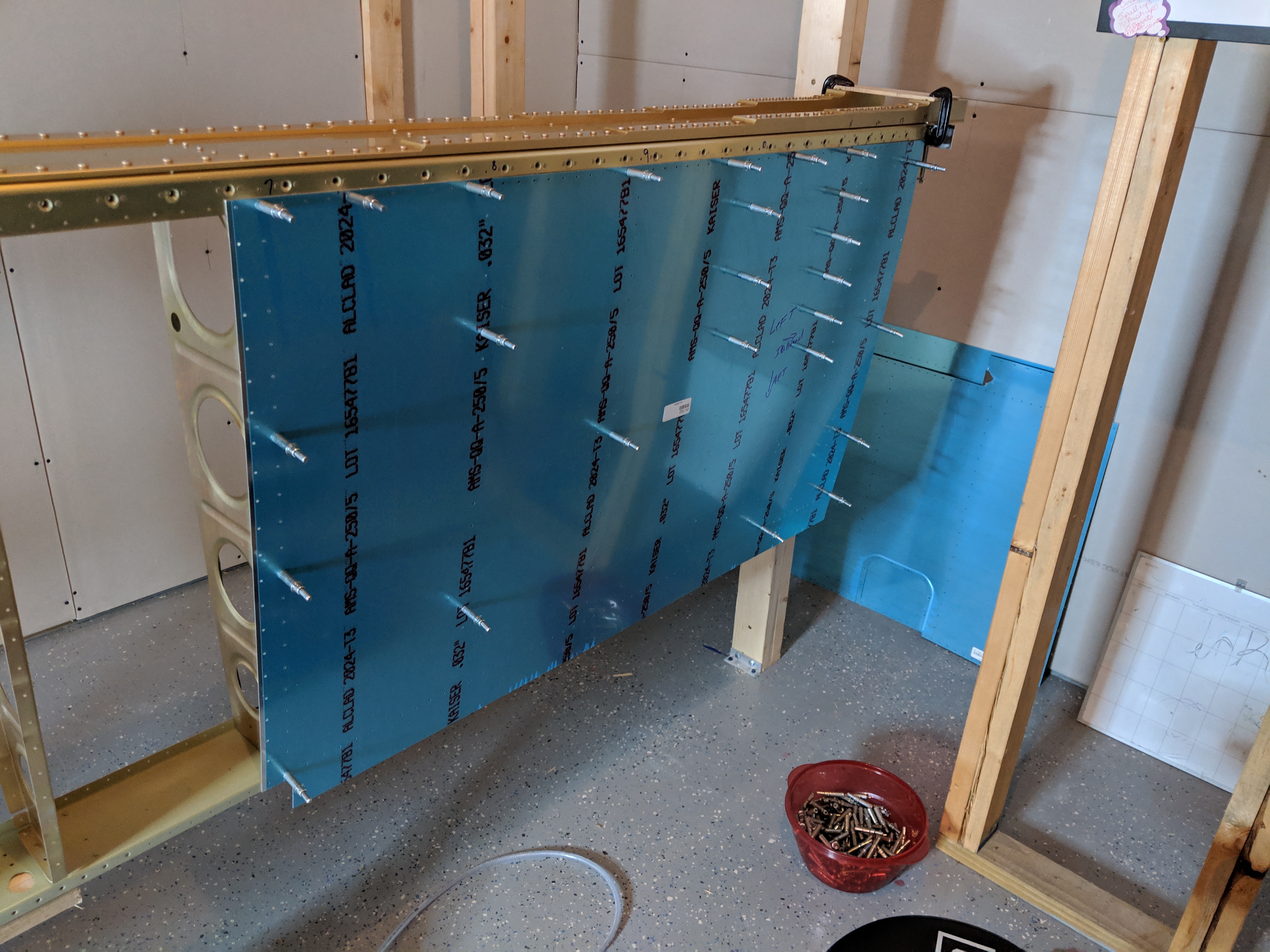
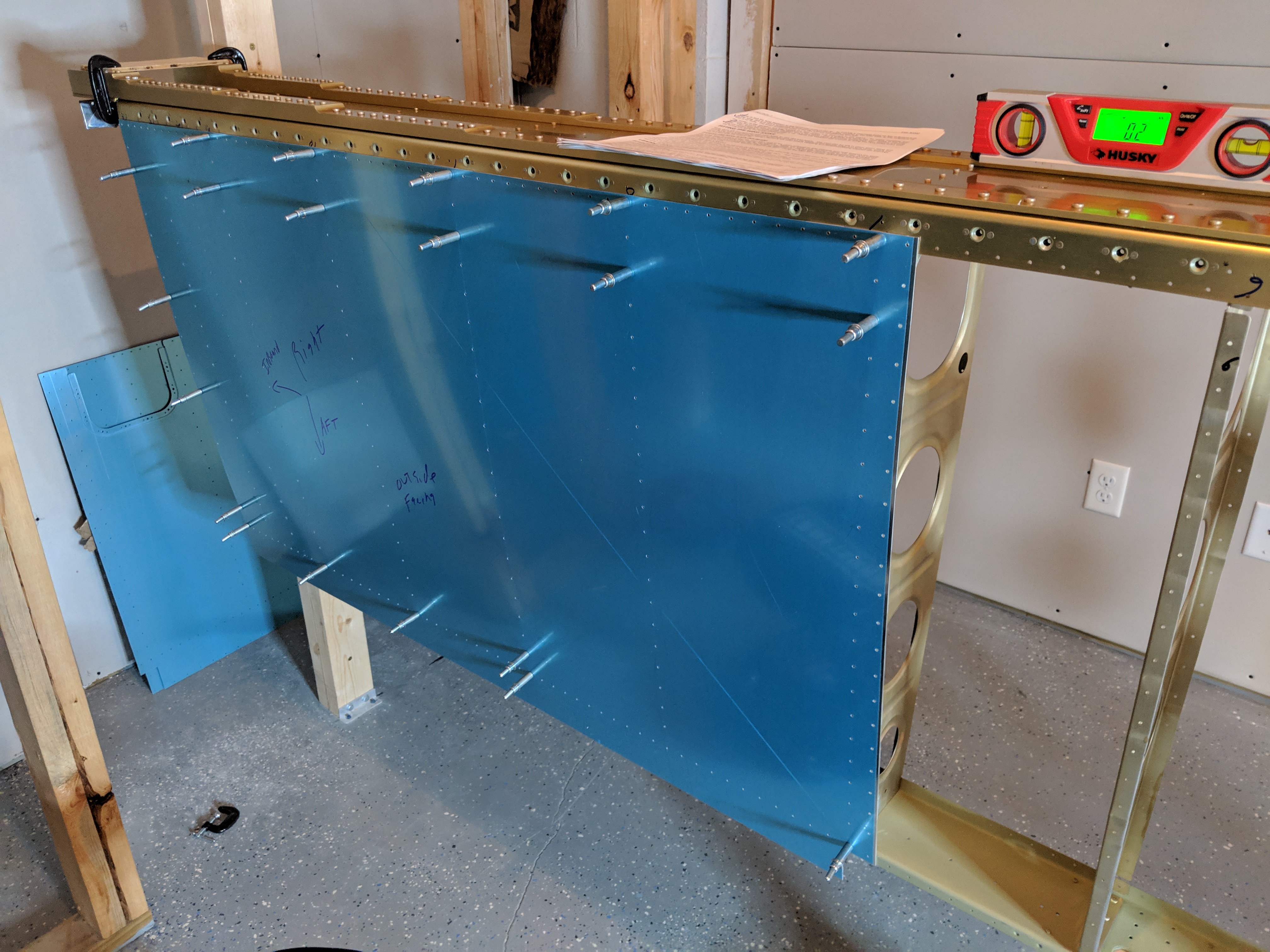
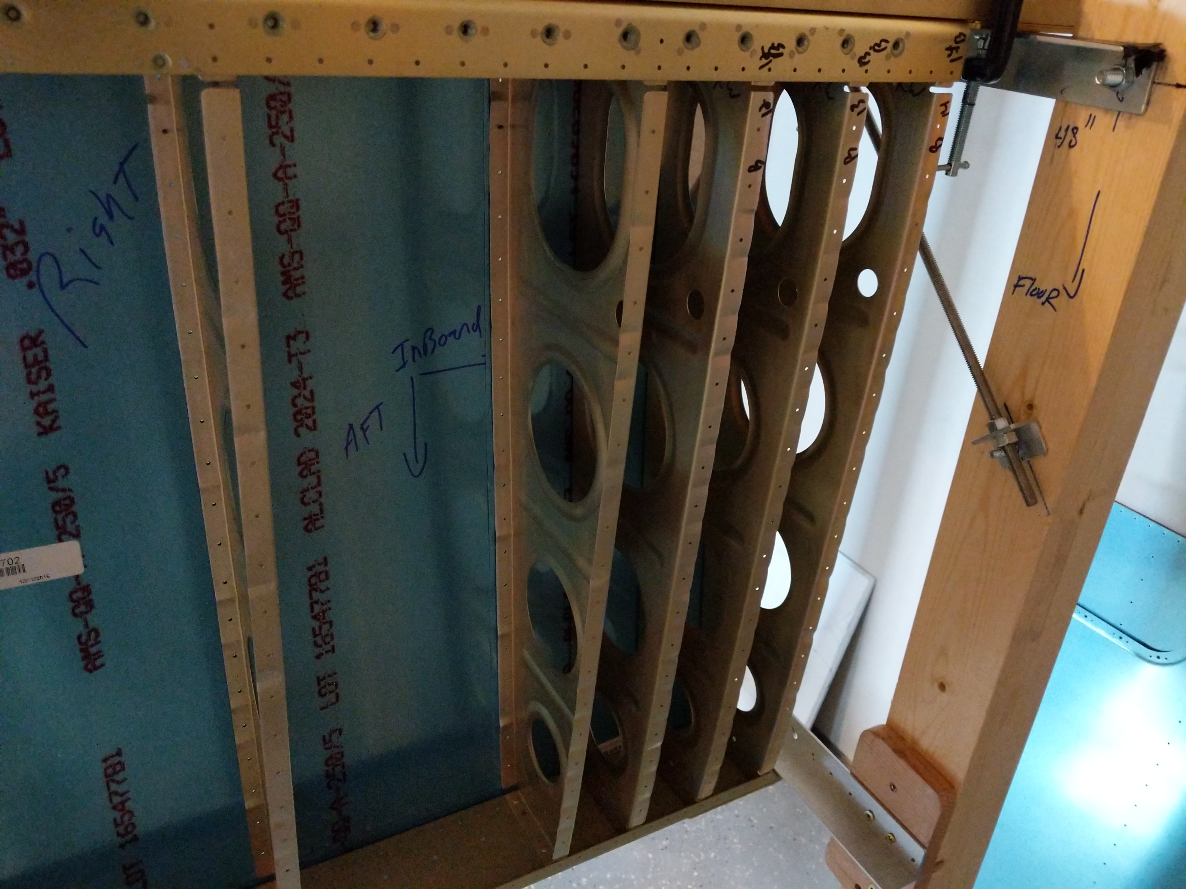
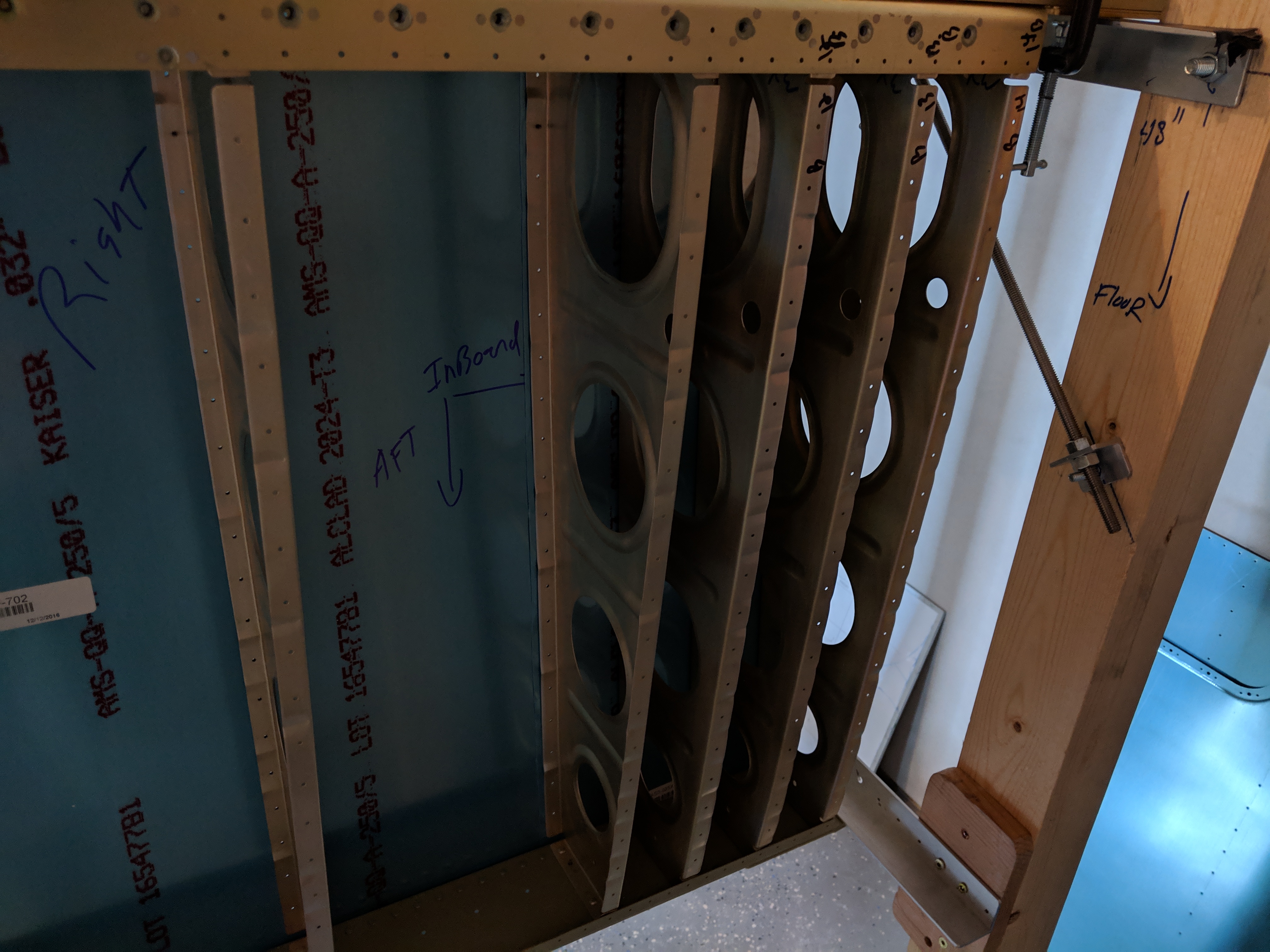
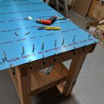
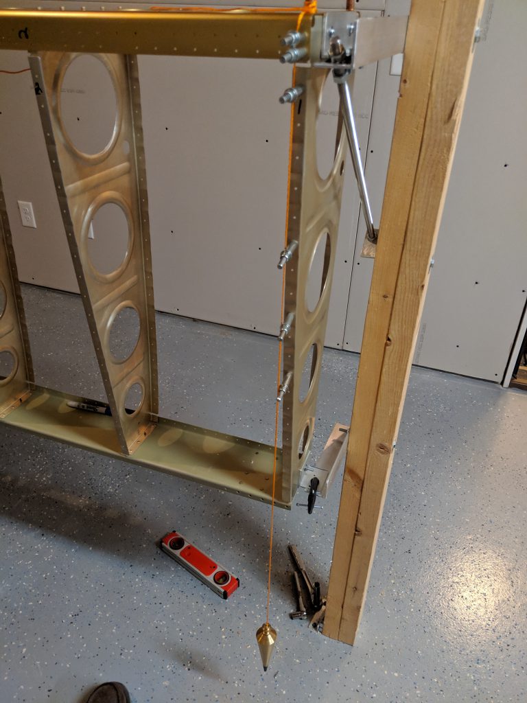
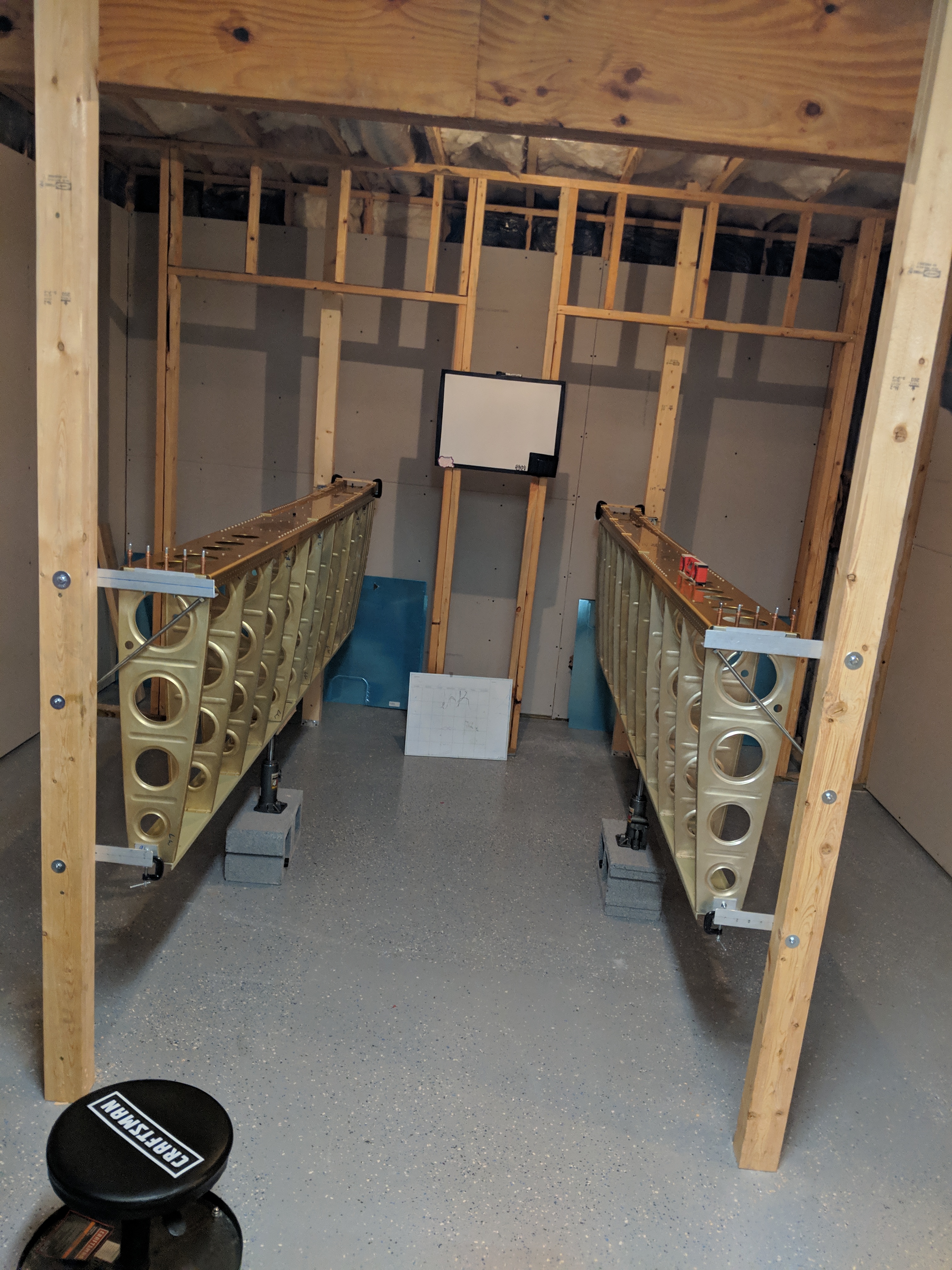
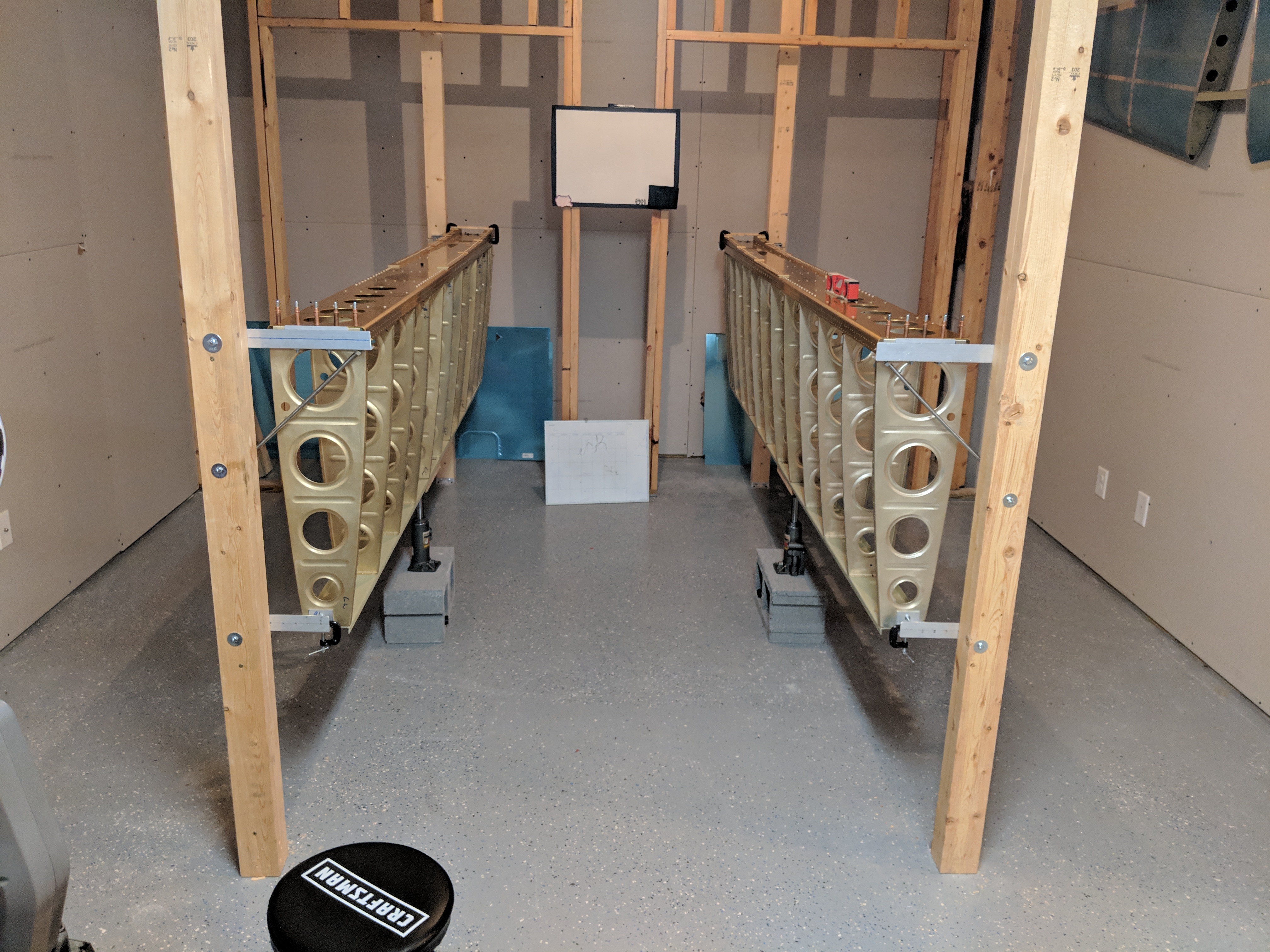
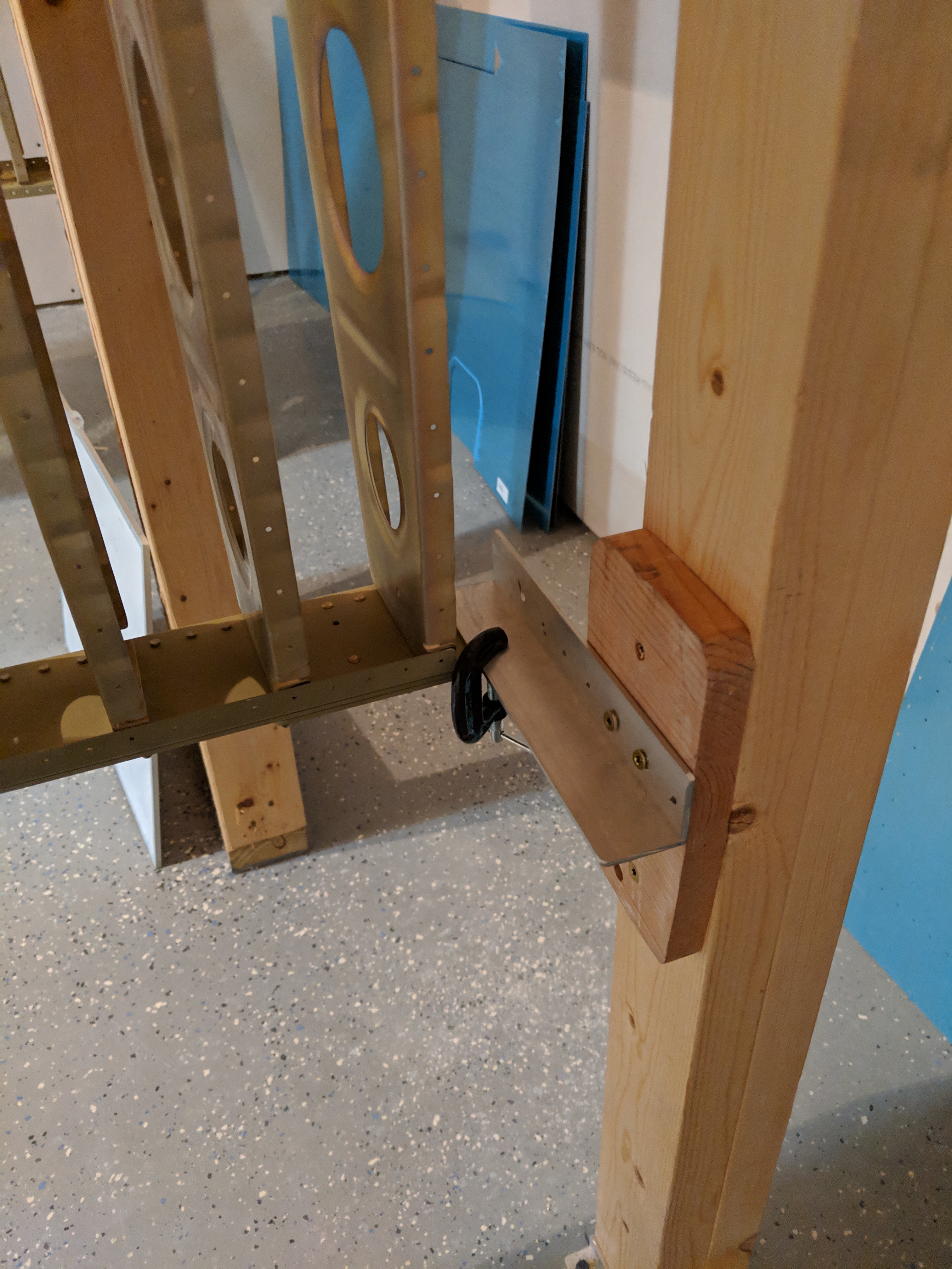
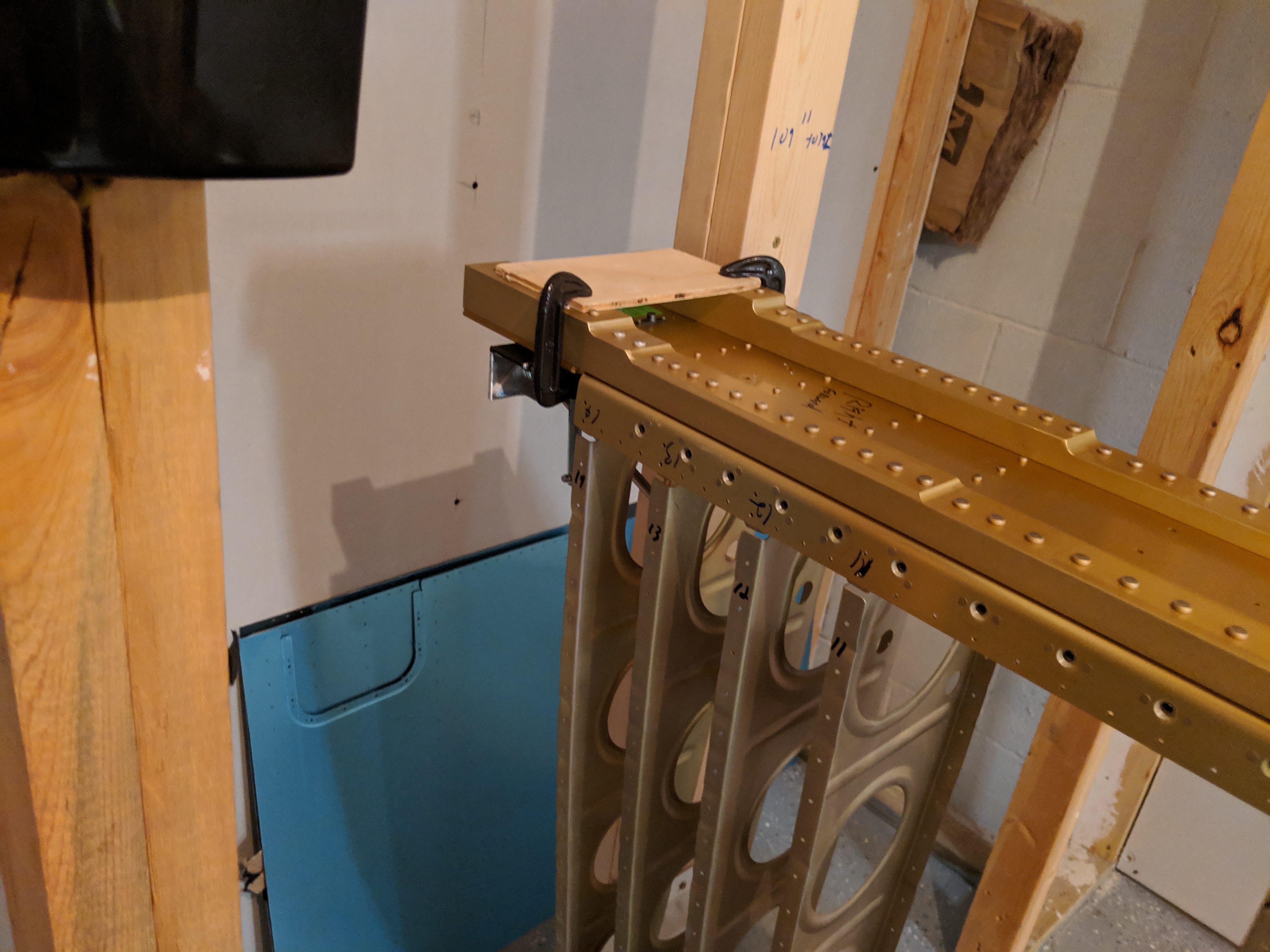
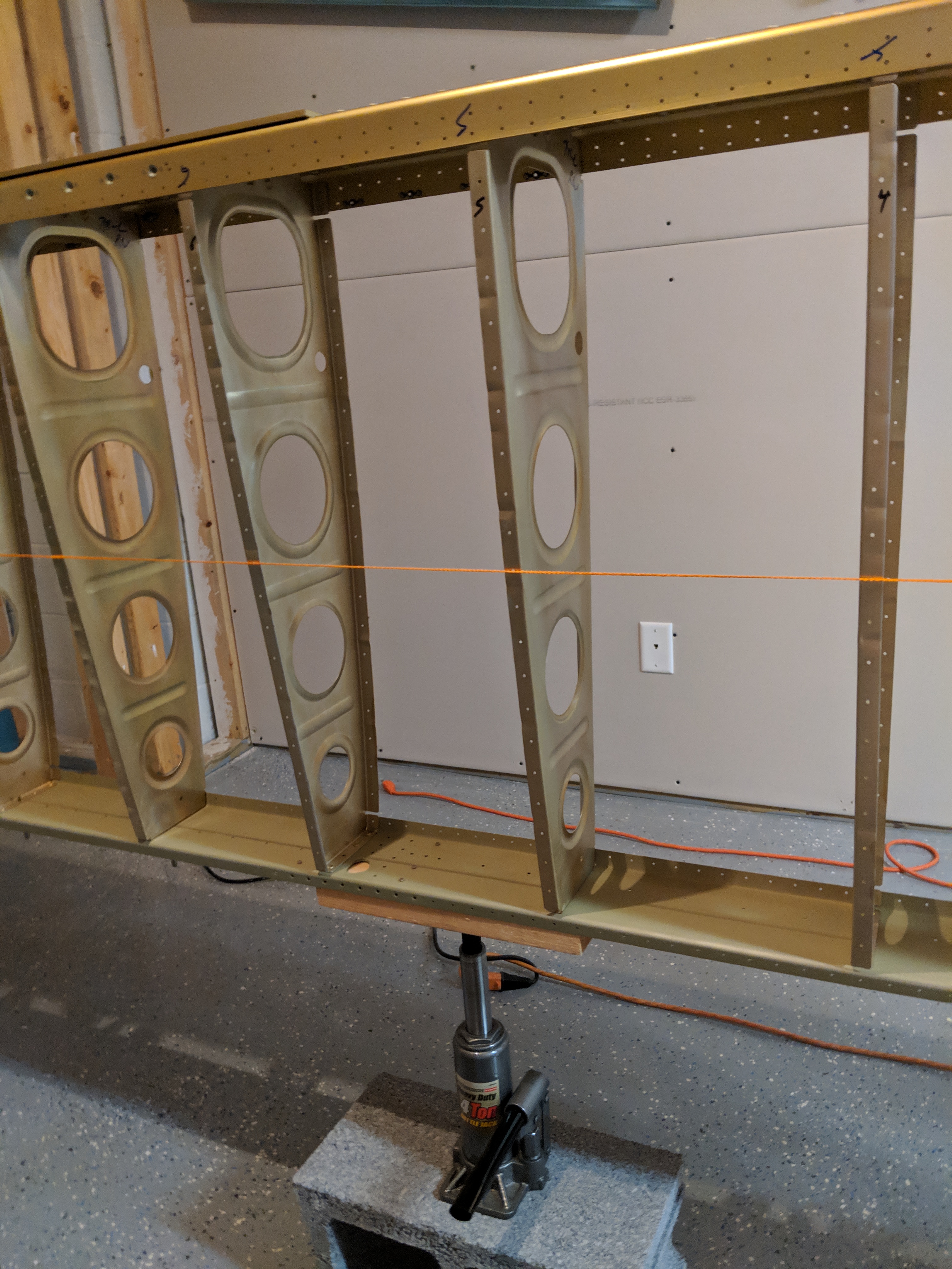
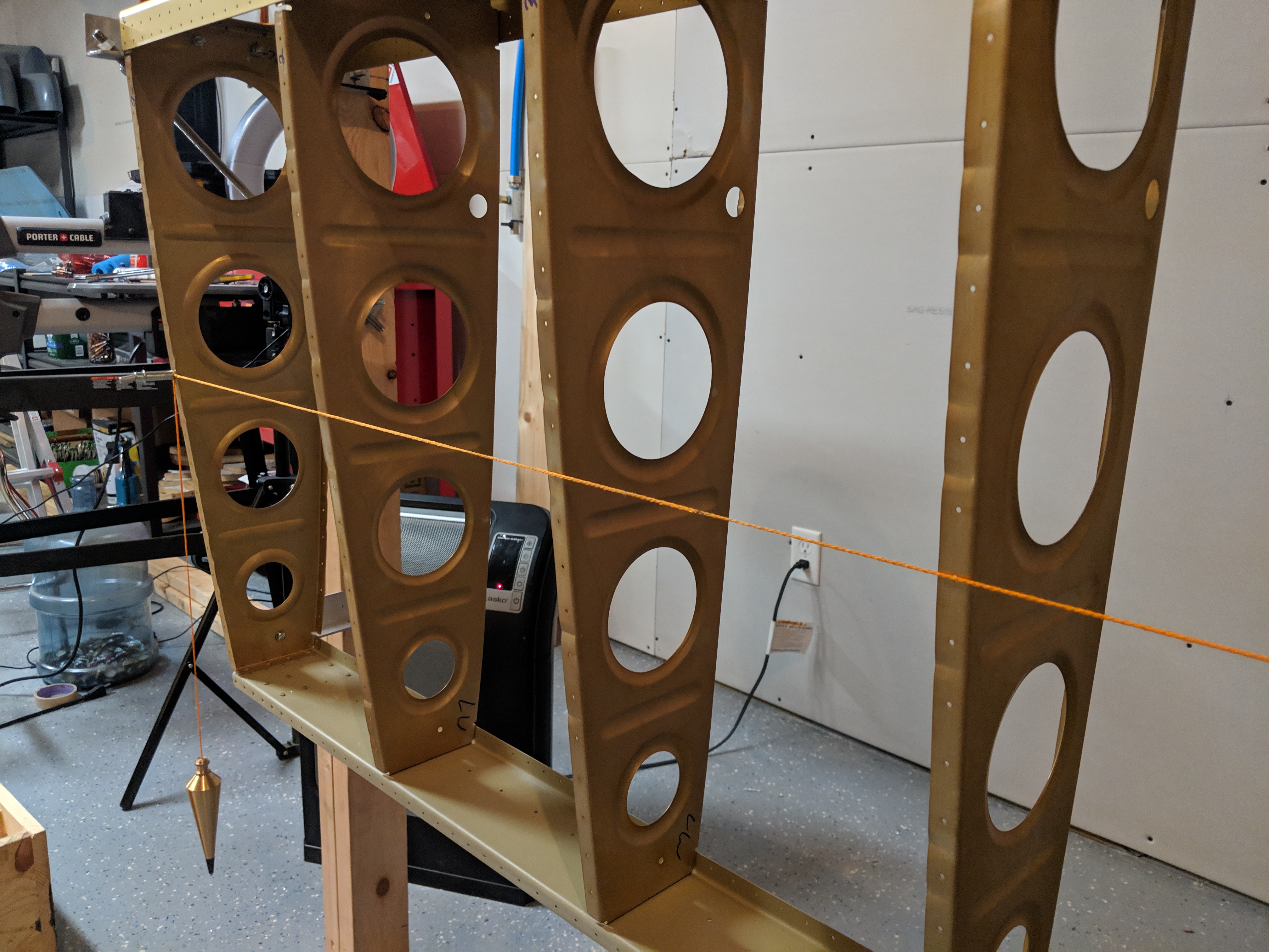
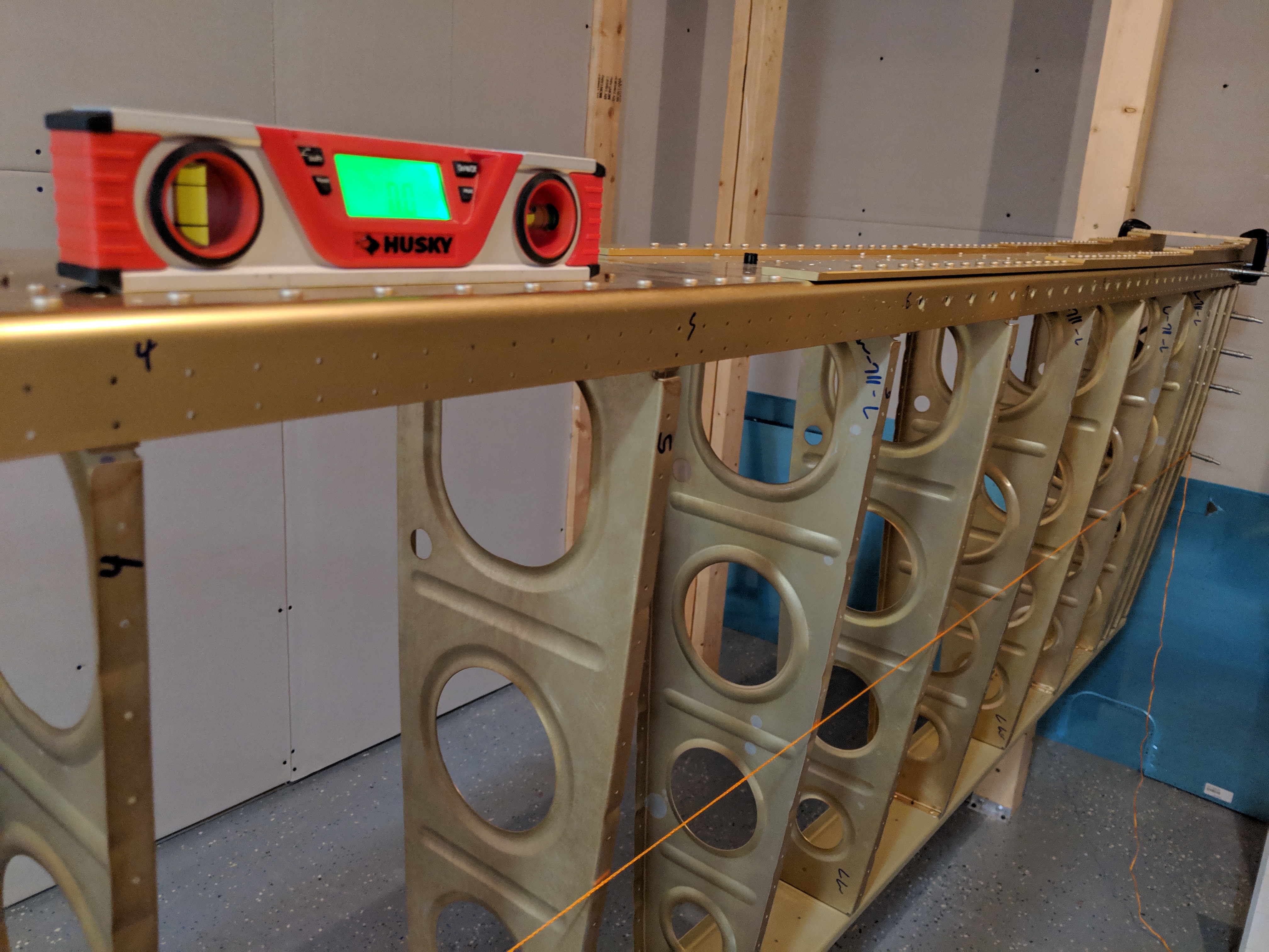
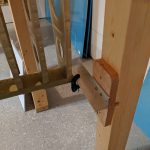
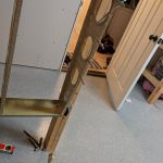
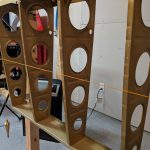
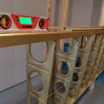
Time to finish up the leading edges….almost.  You see, I realized I made a mistake and back drilled the W-408 ribs too close to the flange bend, and they’ll need replaced.  It happens :-/  But, I did manage to get the right leading edge mounted on the wing.  This is a repeat of the left wing, so I wont go into too much detail.  I started out by getting the leading edge skin mounted into the cradle so I could start clecoing the ribs in place. Then I stuck the ribs in, and clecoed them in starting from the leading edge and working my way back.

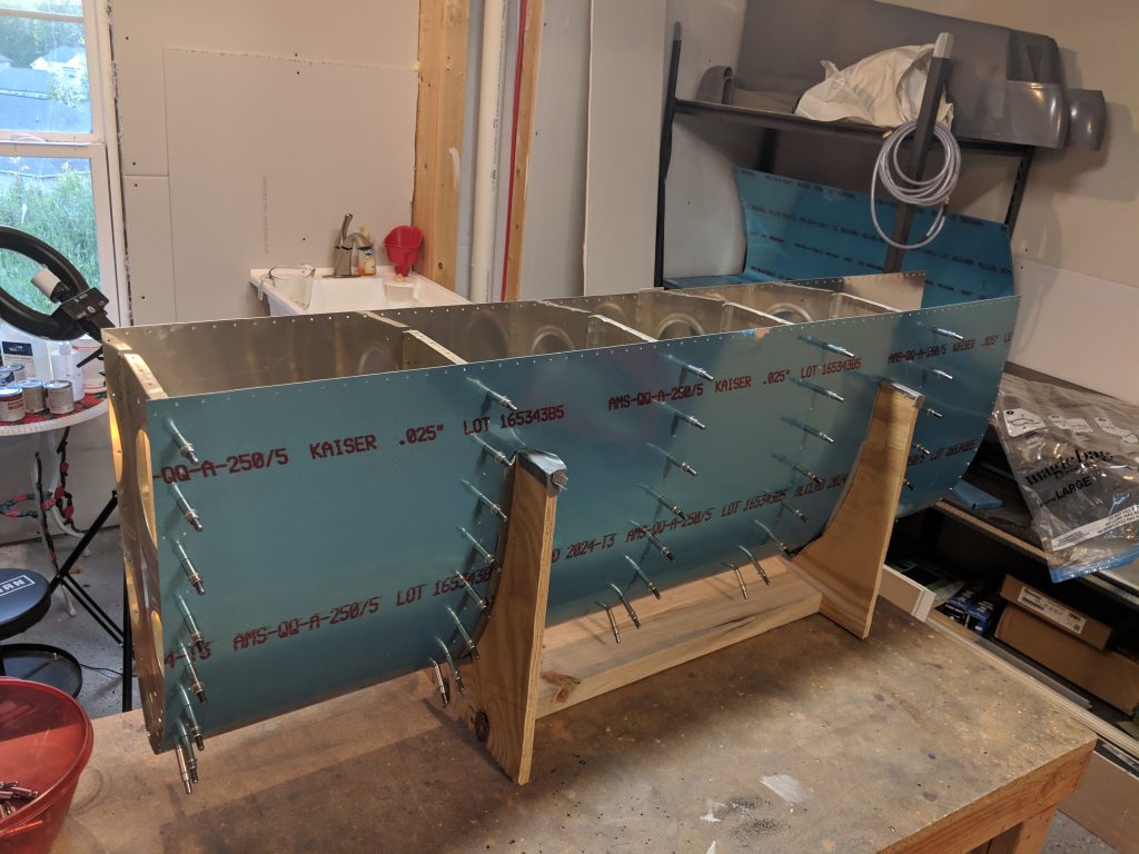
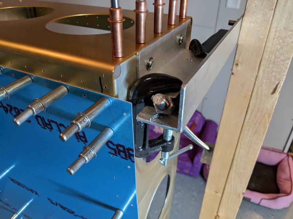
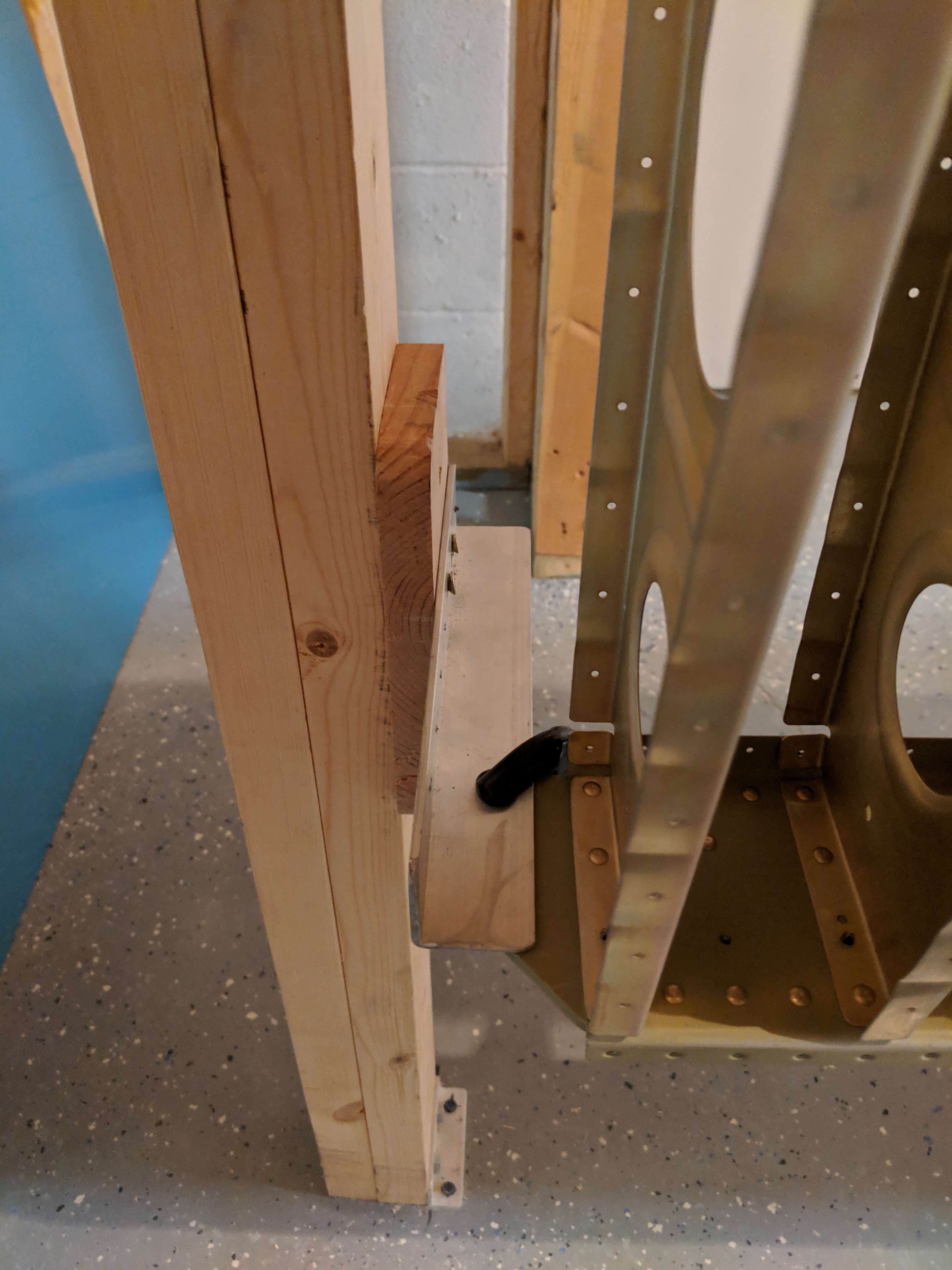
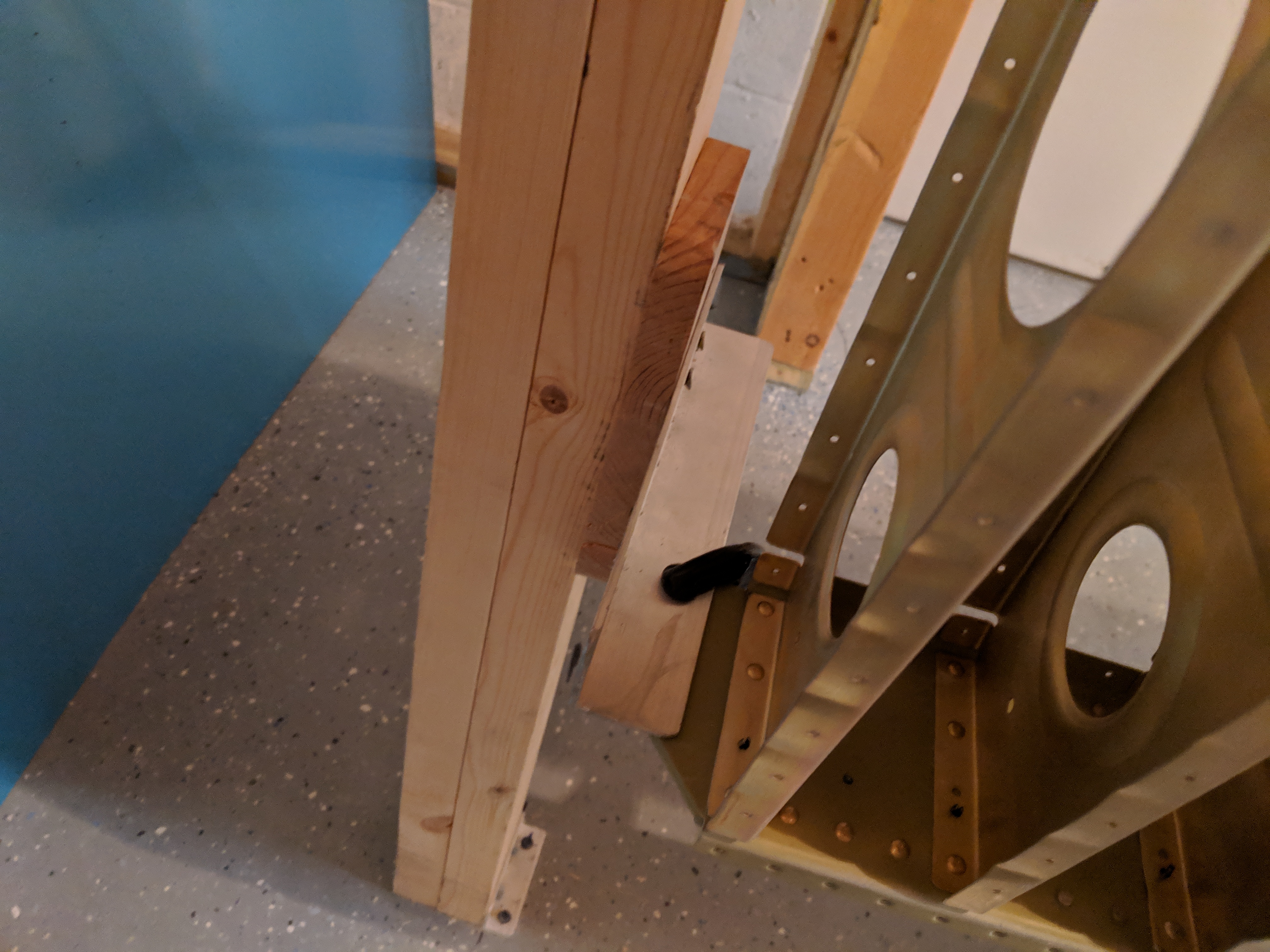
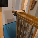
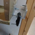
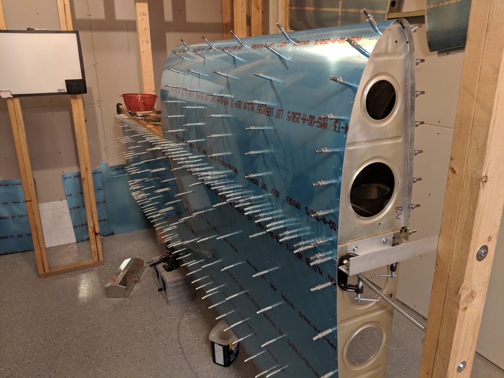
Once I had the leading edge assembled, it was time to mount it onto the spar and start the pain in the but….making the joint plate and back drilling the W-408 rib.  This is probably one of the worst parts about the wing build.  The W-408 isn’t pre-punched, so you have to get the joint plate, rib and skin all lined up just right and then back drill using the skin as a guide.  I messed up my edge distance on this one, as I will note late on in this post.

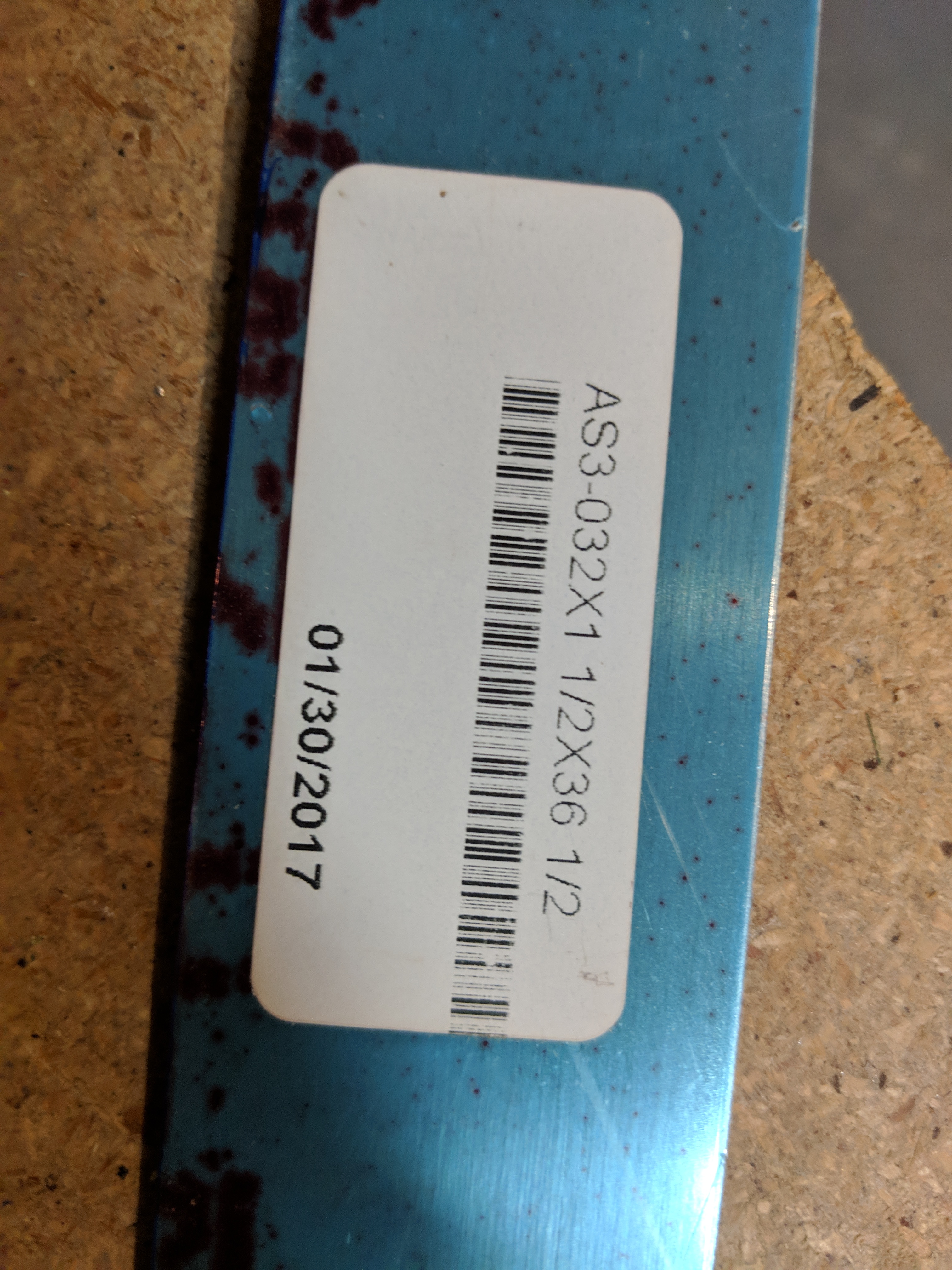
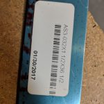
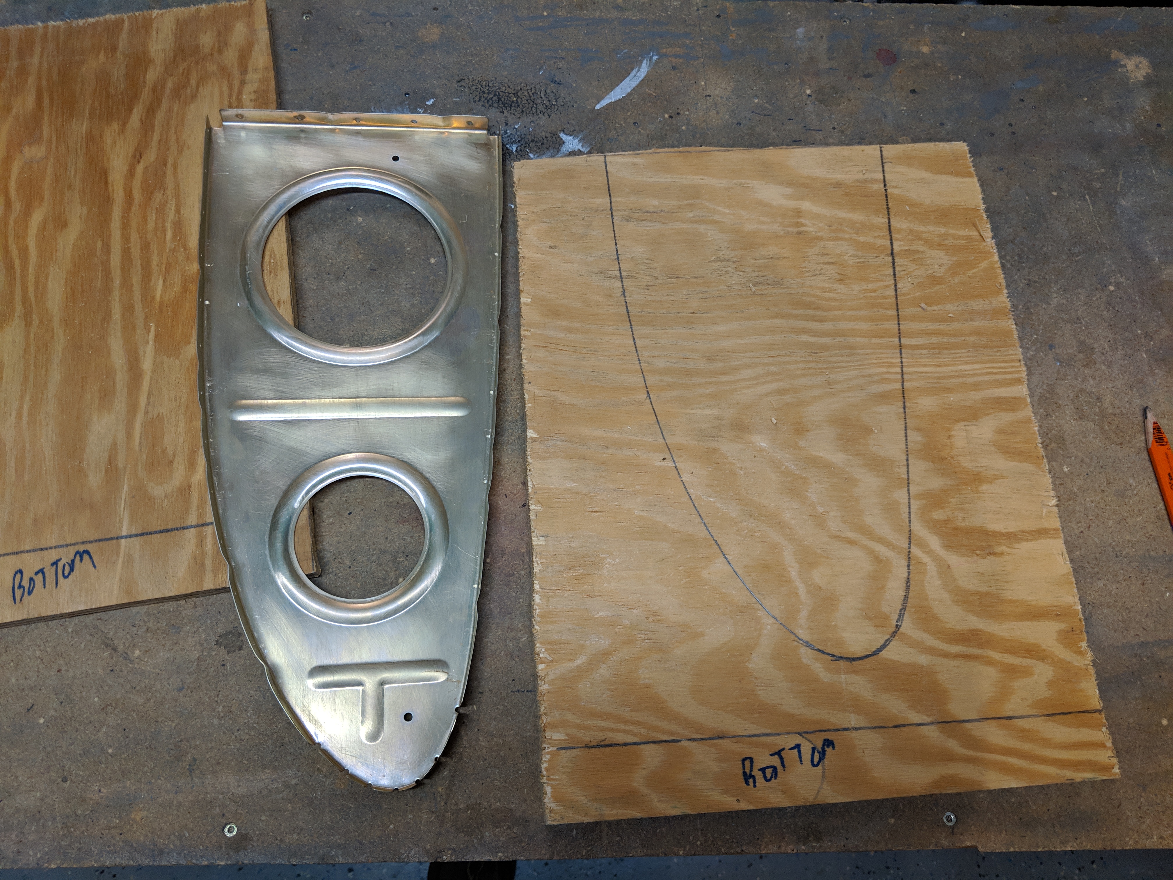
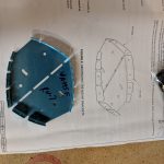
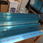
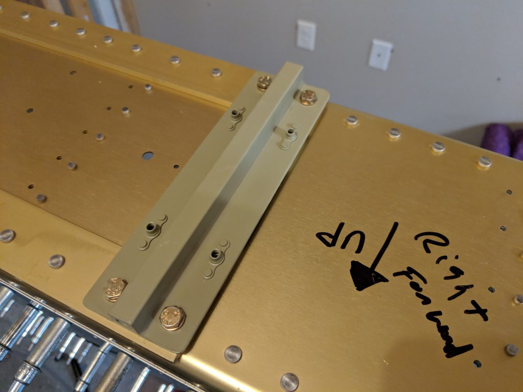
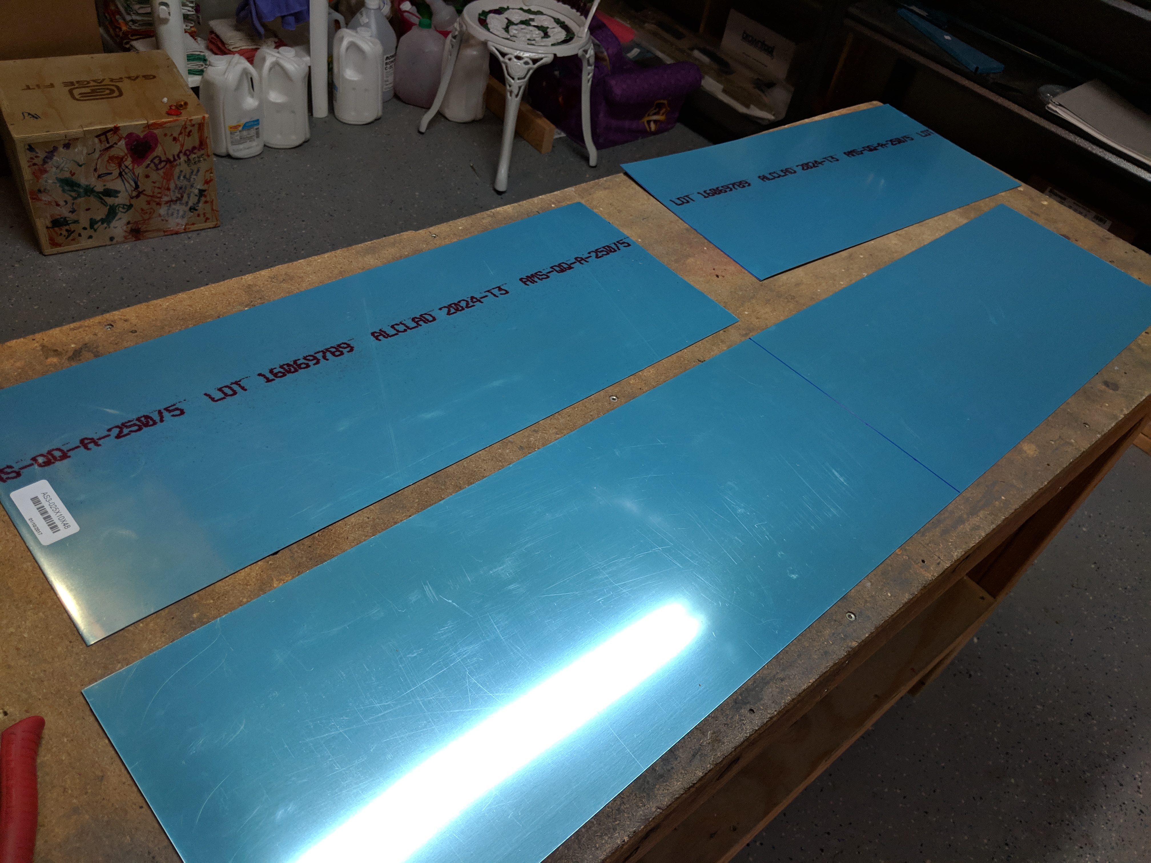
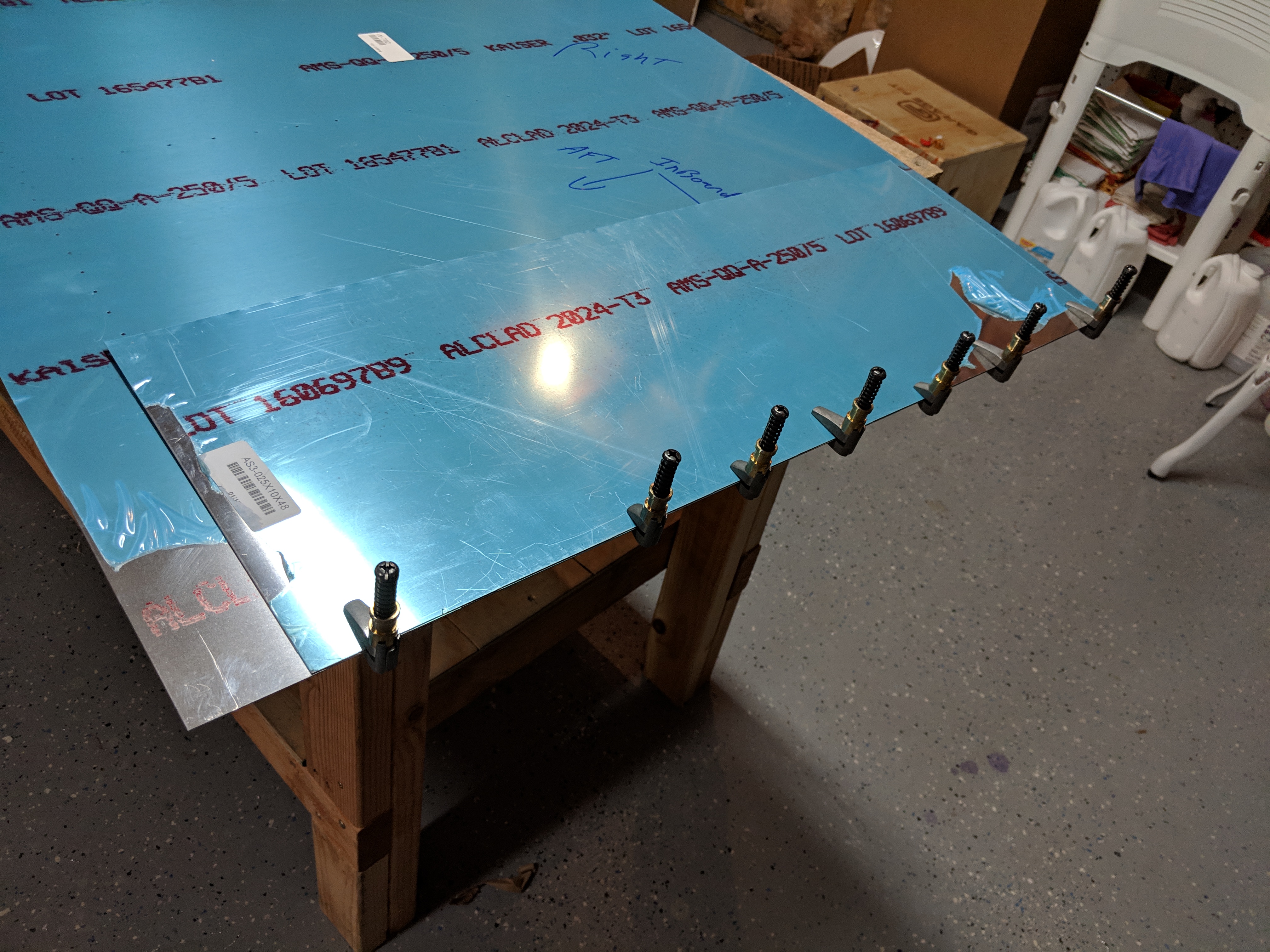
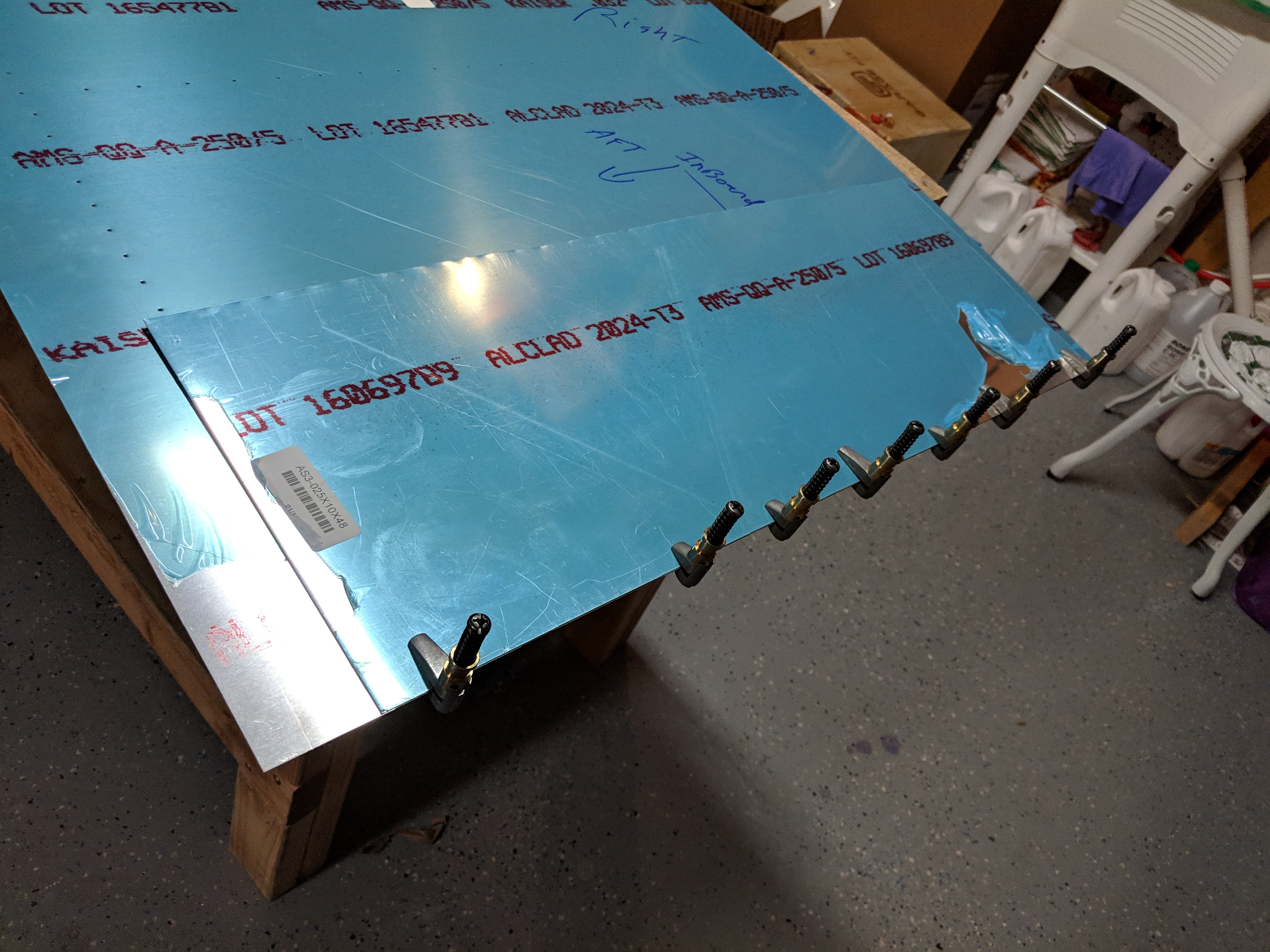
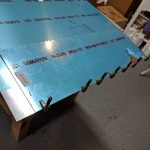
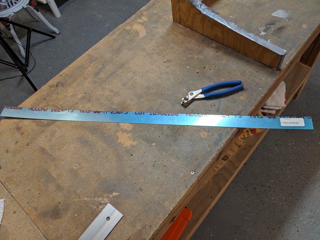
Now its time to make the joint plate.  Van’s has the dimensions in the plans for this strip, but I have found that they actually sent two pieces (one for each wing) that was already cut to the dimensions, which was nice:

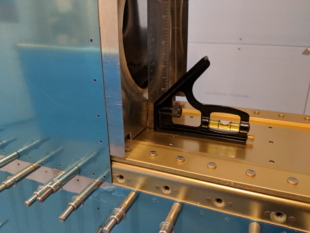
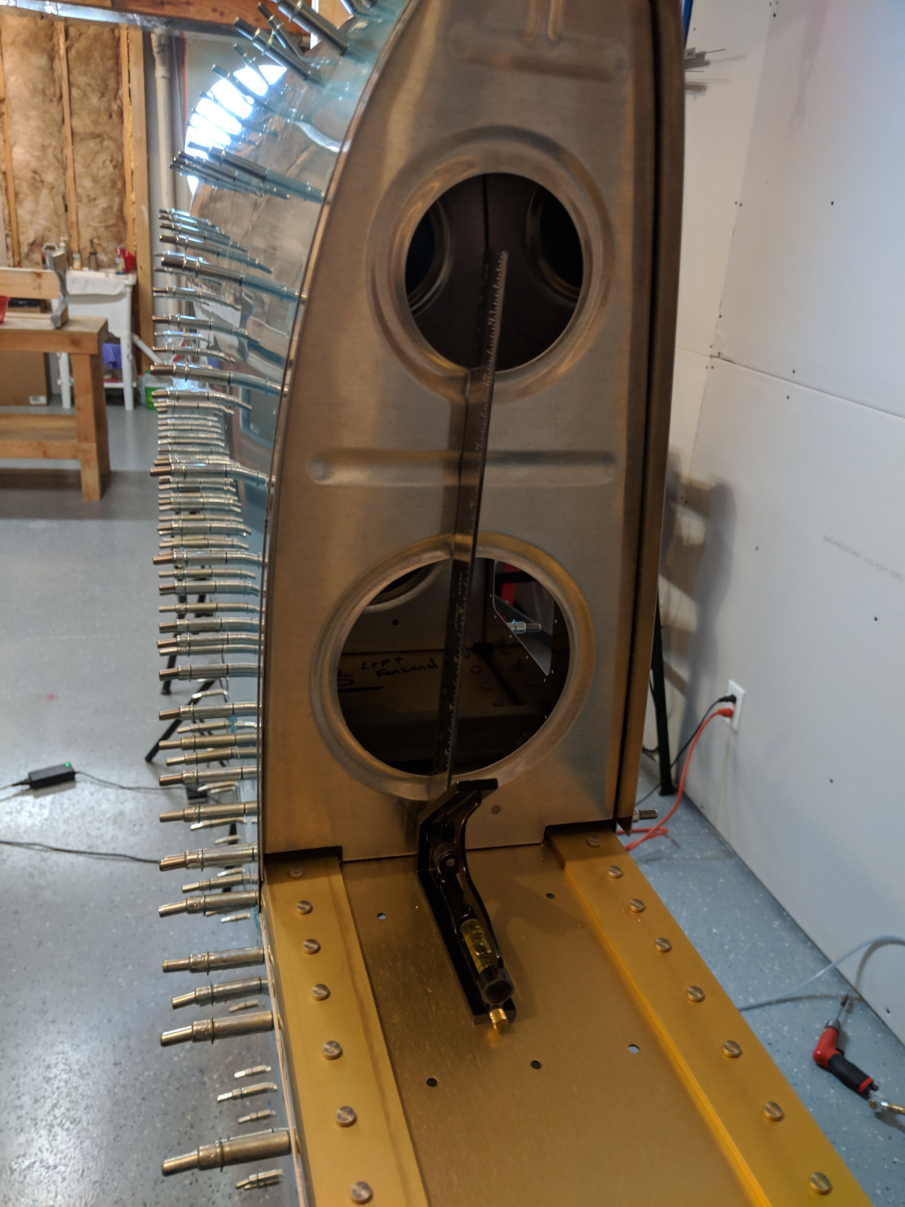
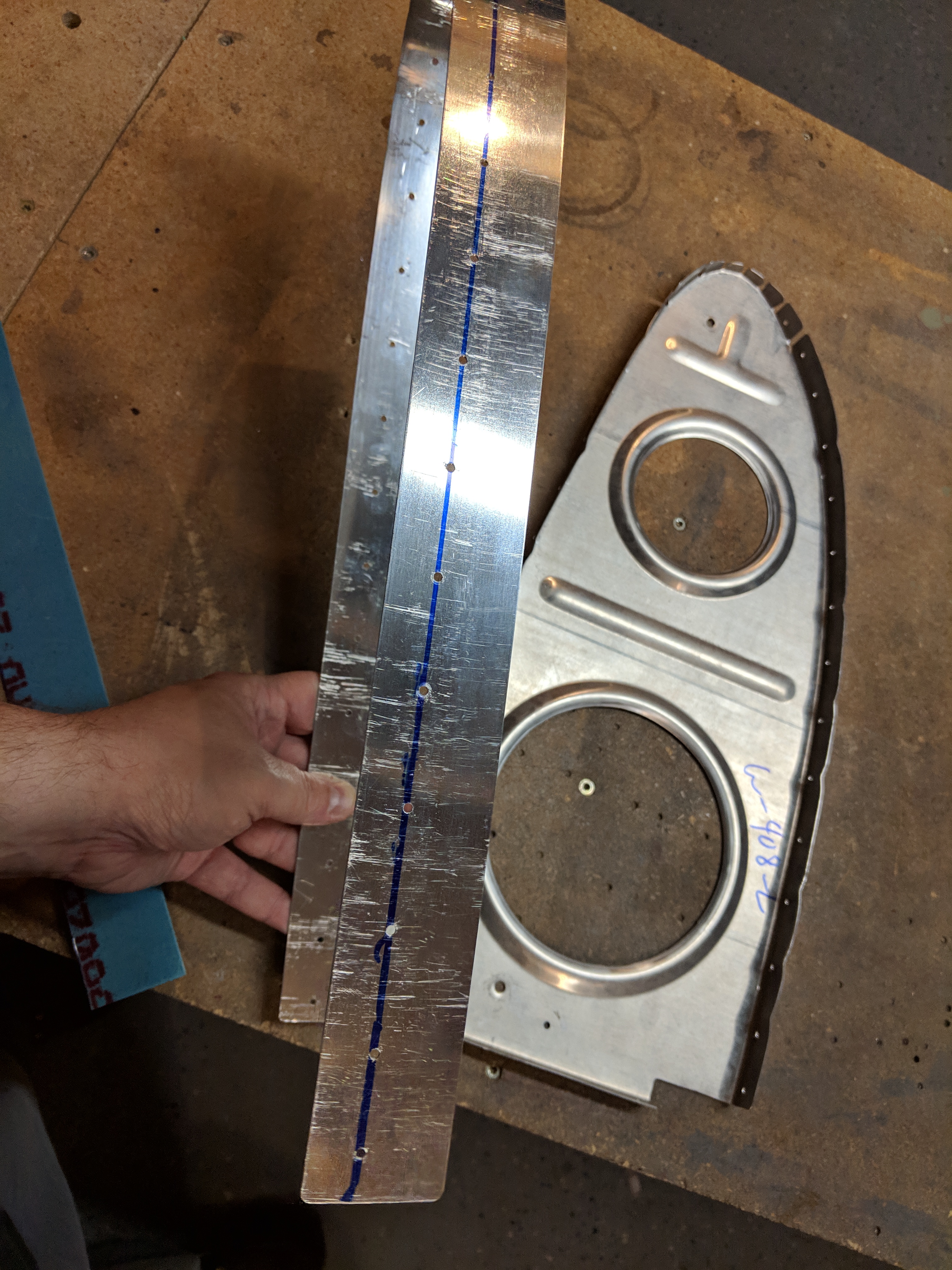
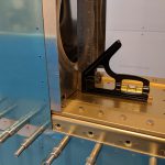
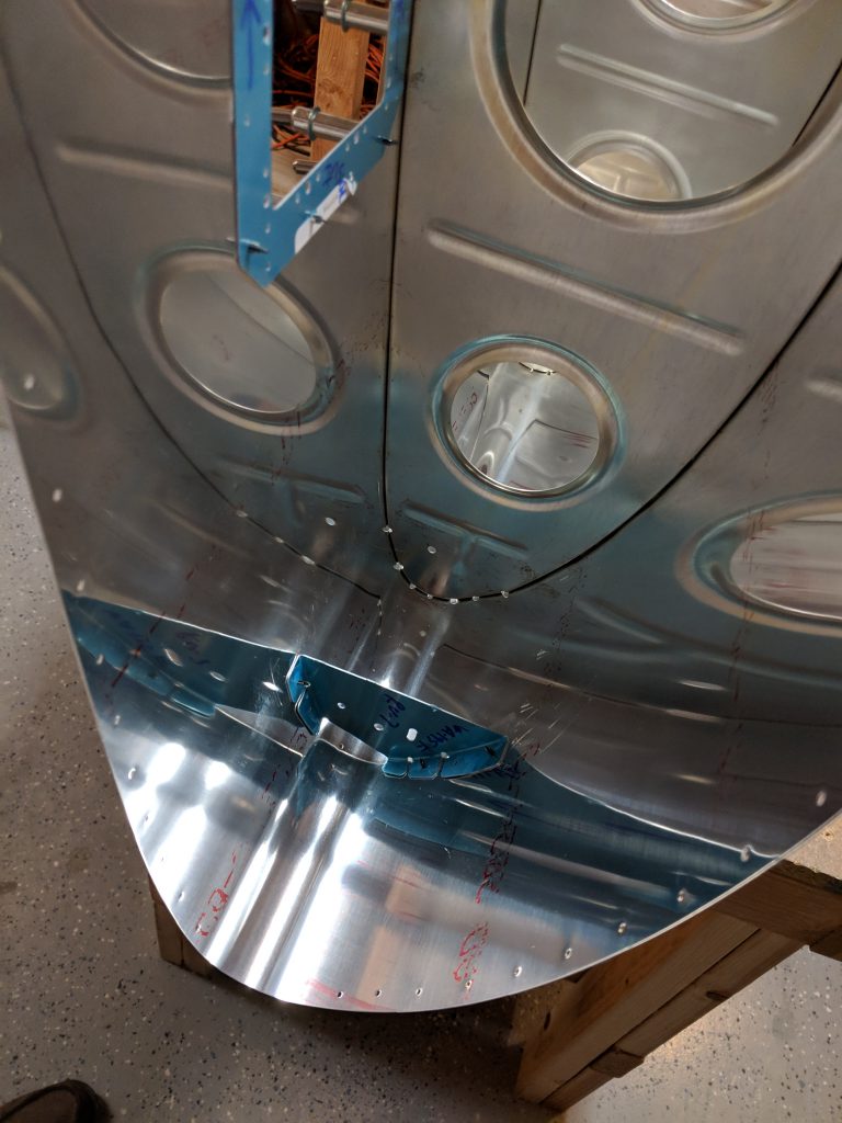
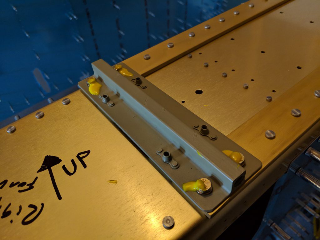
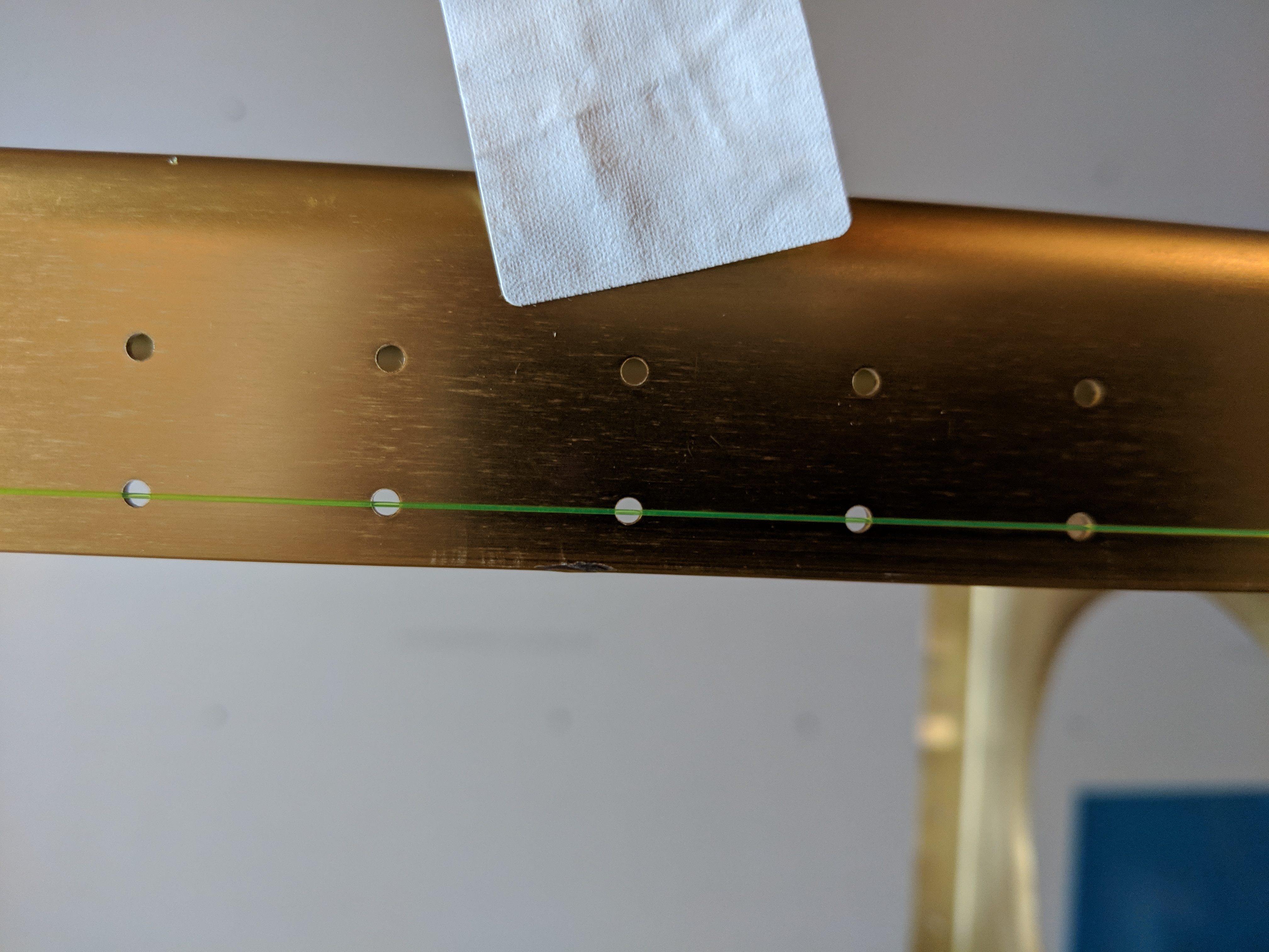
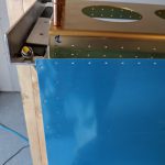
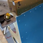
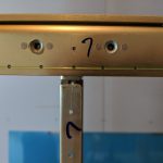
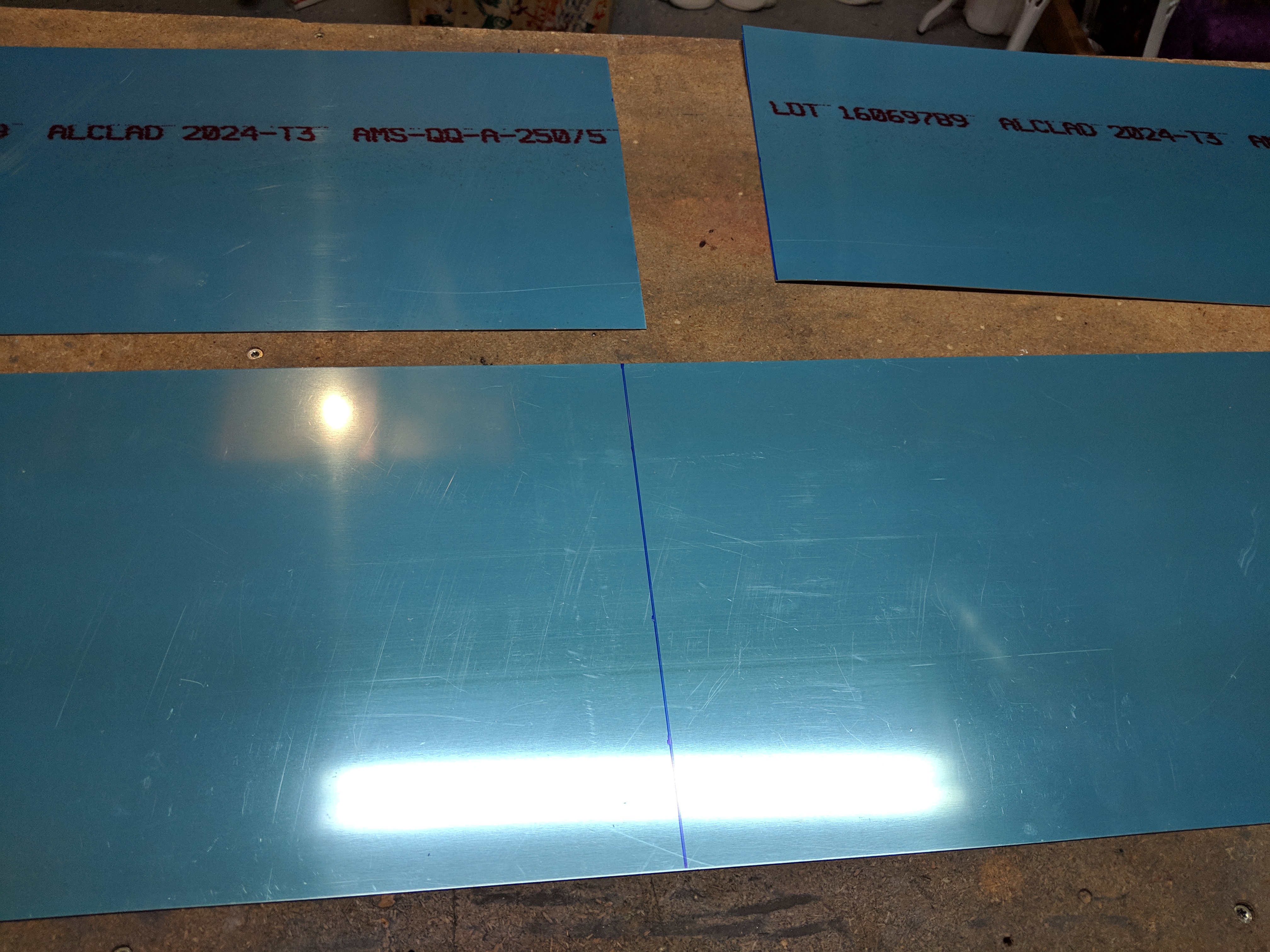
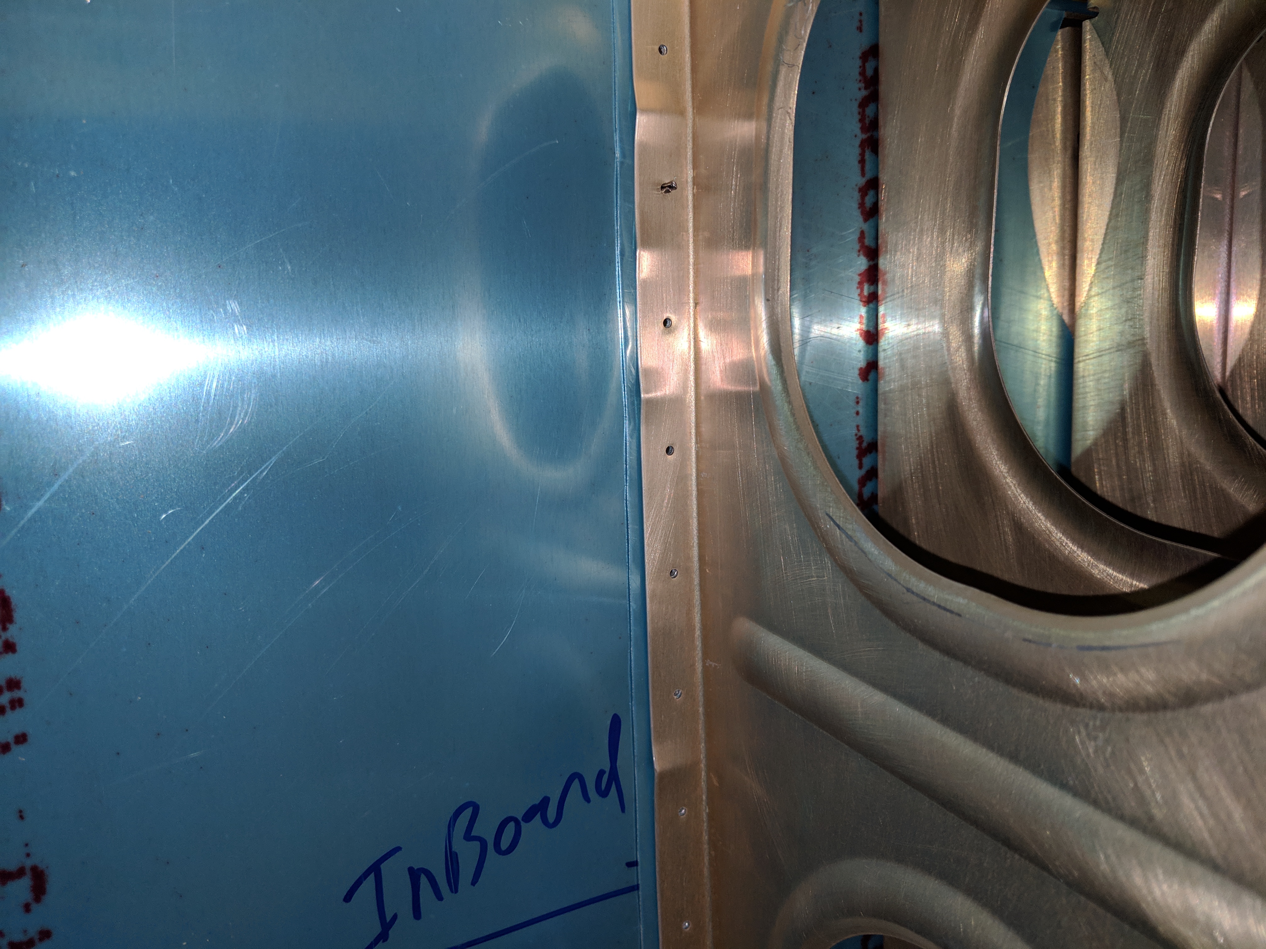
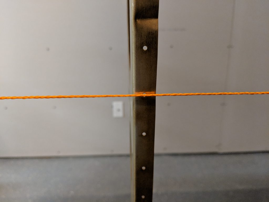
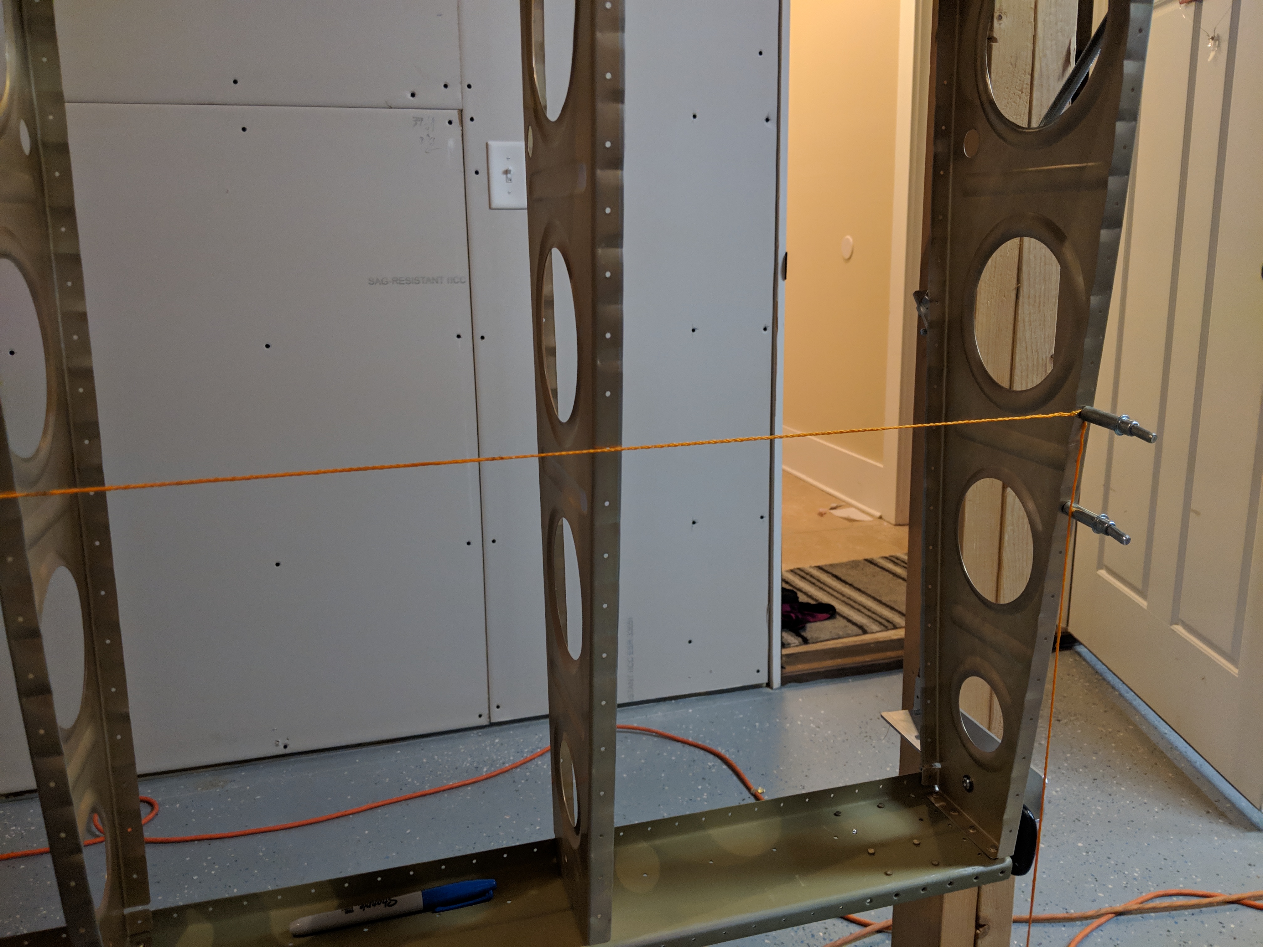
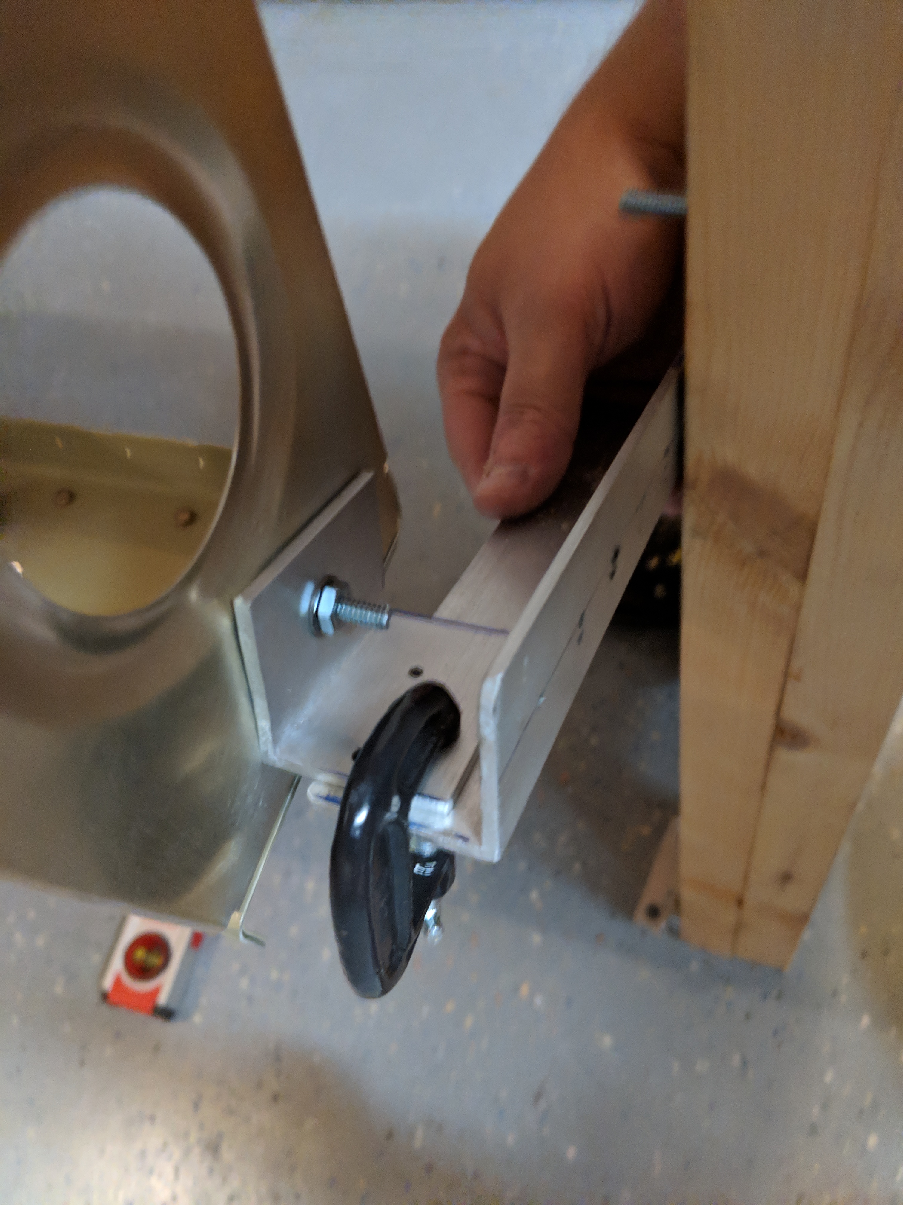
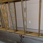
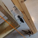
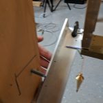
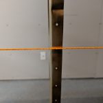
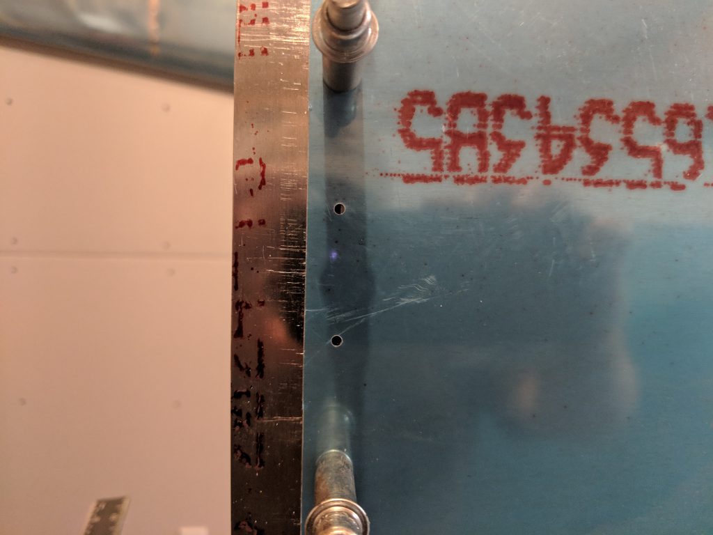
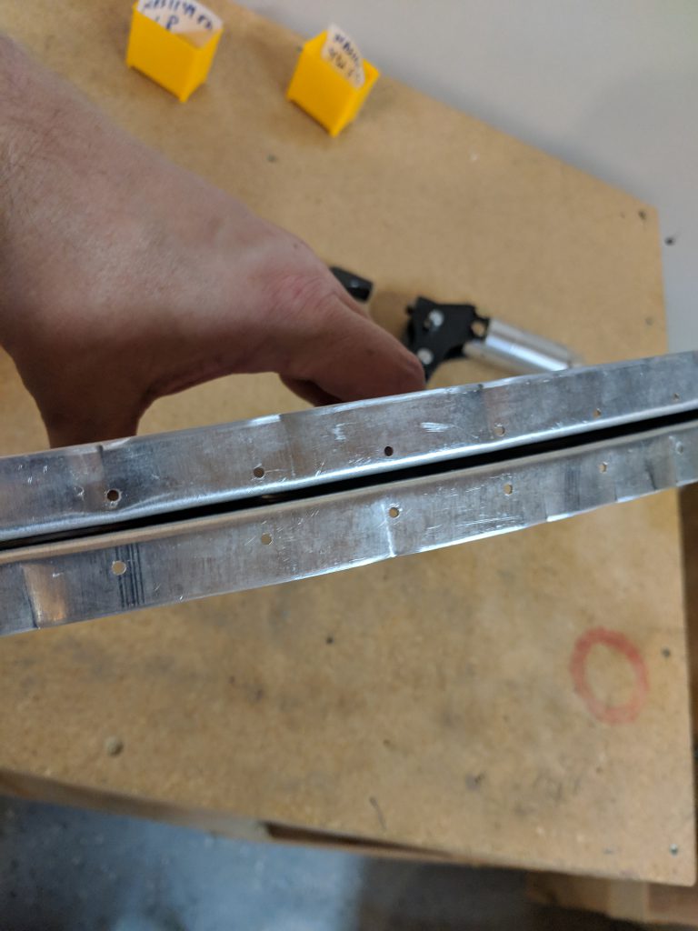
I removed the plastic and marked a line 1/2″ from the edge per the instructions.  This line is used to line the joint plate up with the skin. After that, I marked the center of the flange on the W-408-1R rib that rivets to the spar.  This was so I could see where I should line up the rivet holes on the spar for match drilling. Then I slipped it into place with the leading edge, lined up the blue line with my spars rivet holes and match drilled them using a #30 bit. These holes turned out great:

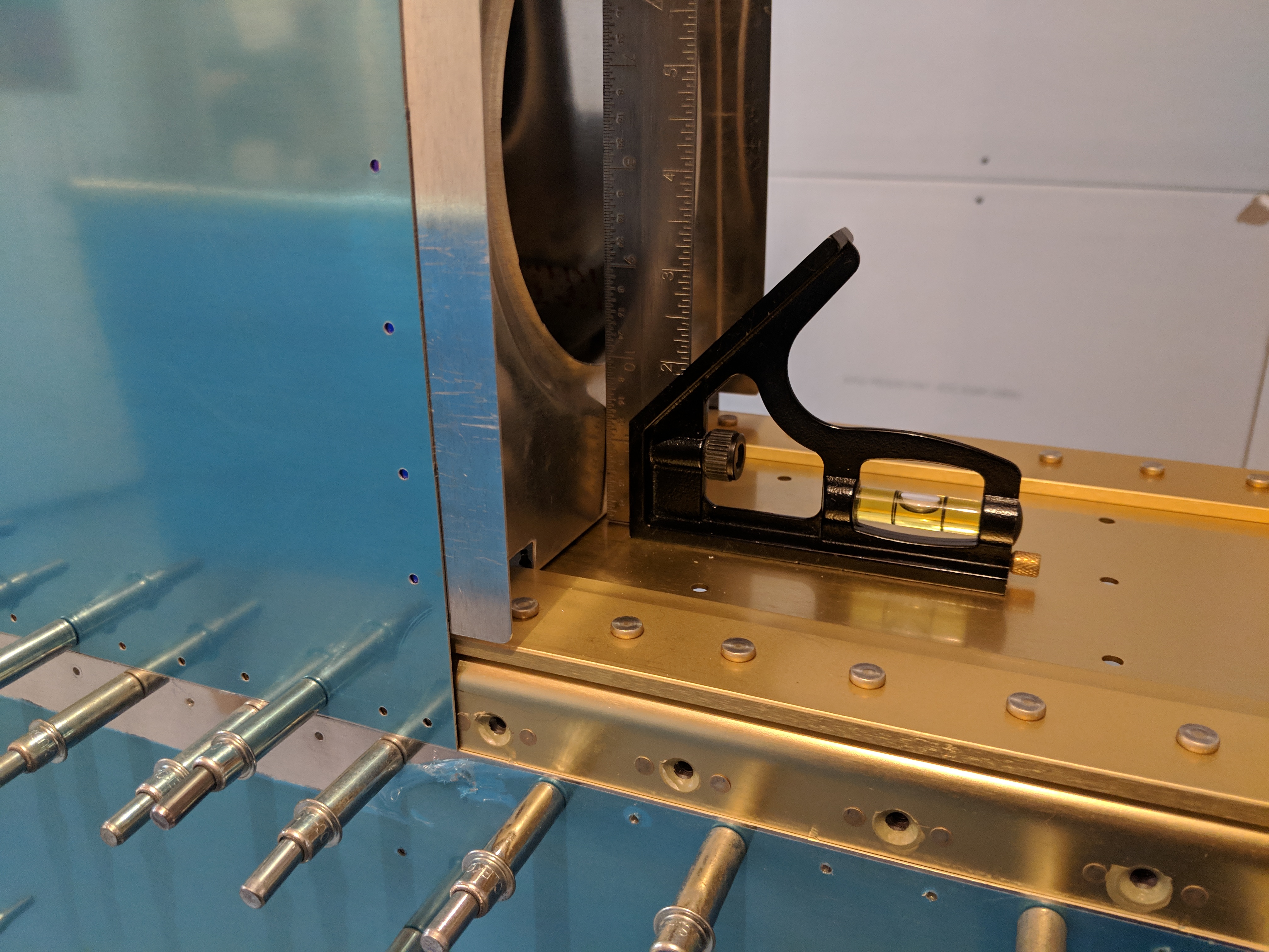
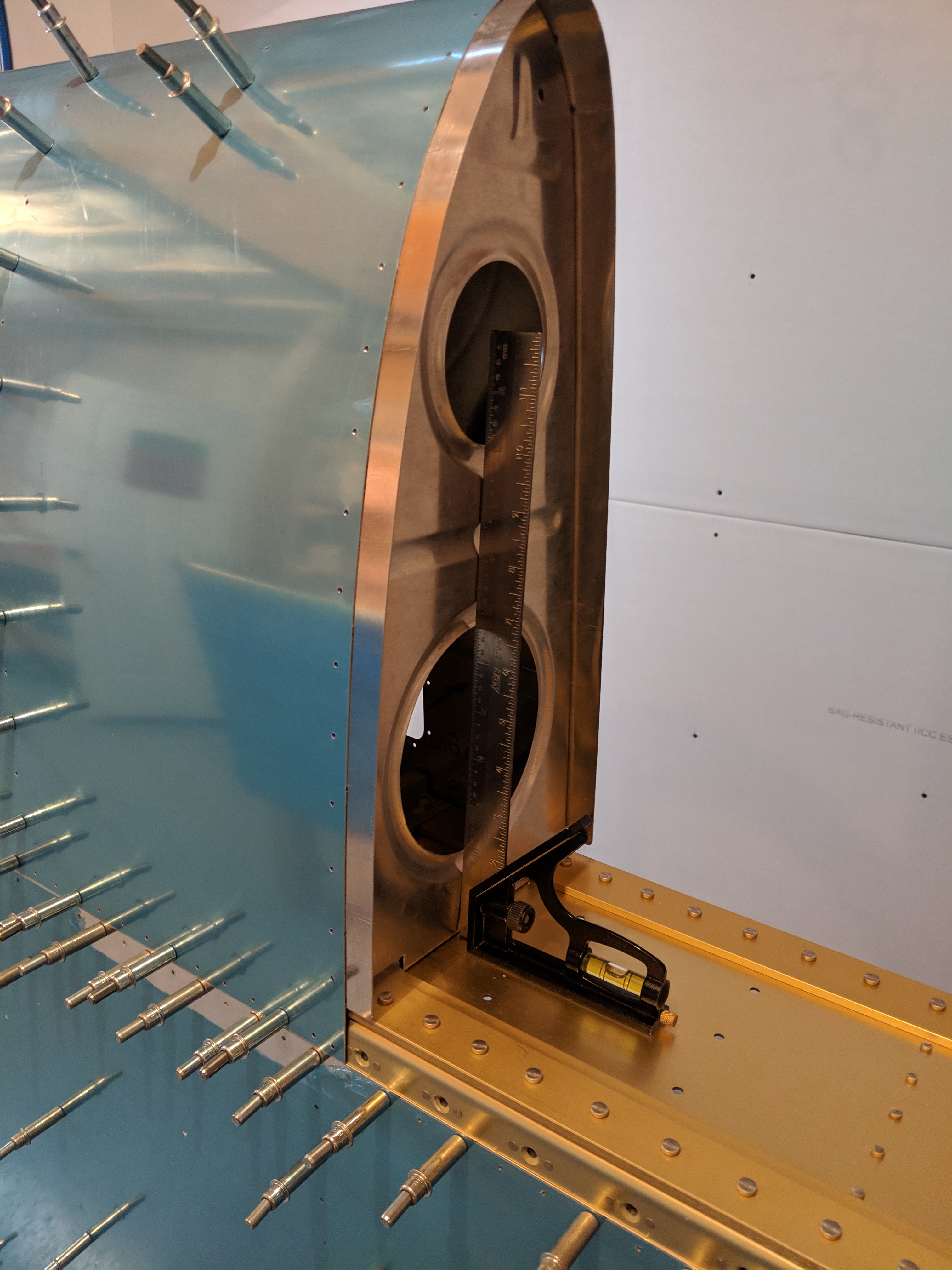
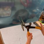
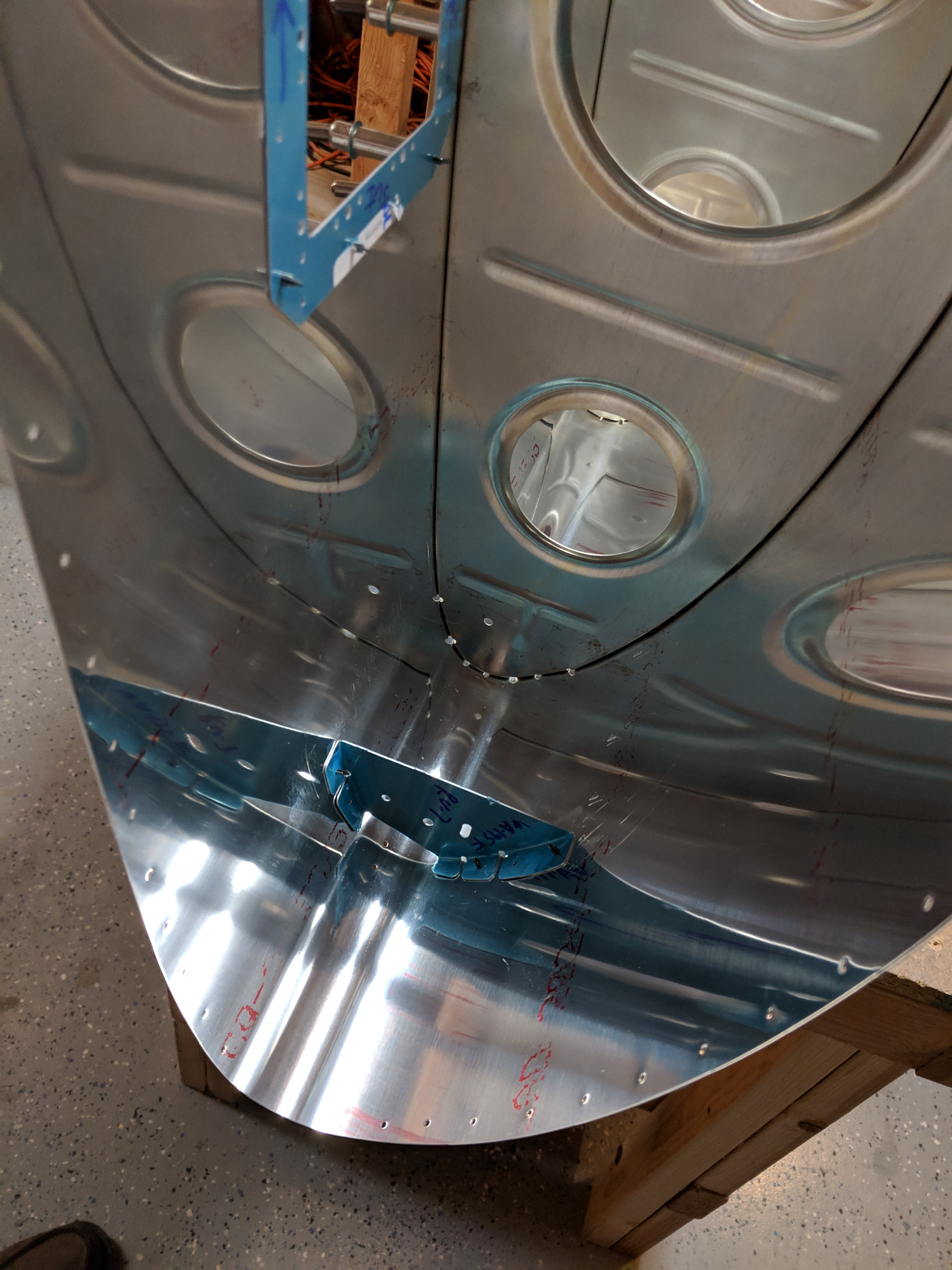
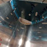
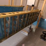
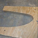
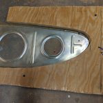
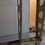
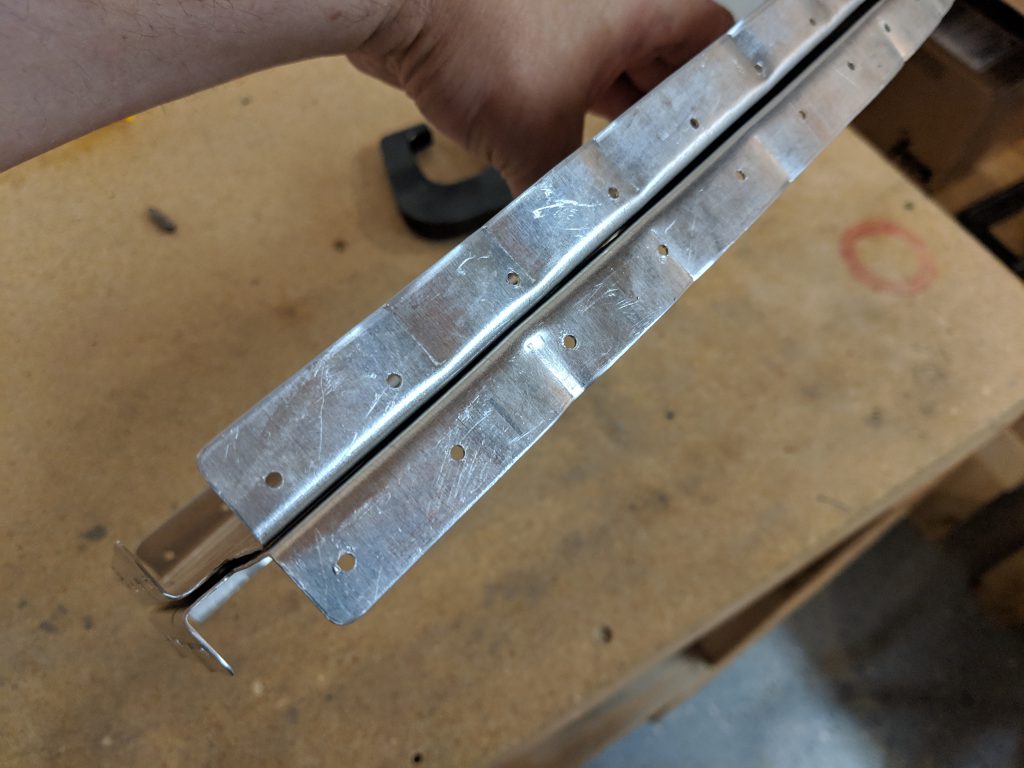
Now the fun part.  Trying to form the joint plate into the shape of a leading edge.  I remove the W-408 rib that I had just drilled (in the photo above) so I could use it as a template for my initial hand-bending.  After a good while I sort of got it to resemble the shape of a leading edge. Then I re-clecoed the rib’s flange to the spar, and started working the joint plate into the small gap between the W-408 rib, and the skin.  After fiddling and tapping and fiddling and moving, etc I finally had the blue line I marked on the joint plate lining up with the holes in the skin.  I had thought that the plans said we’d need 11/16″ inch from the rib to the outside edge of the joint plate, so thats what I did:

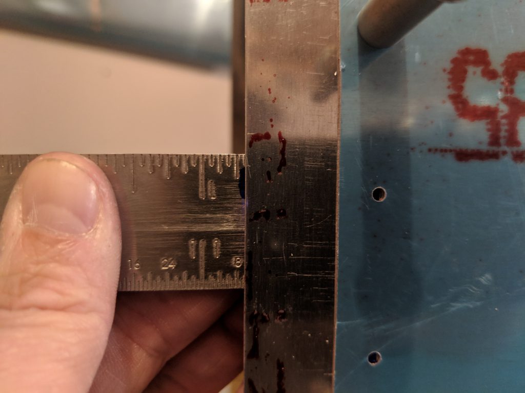
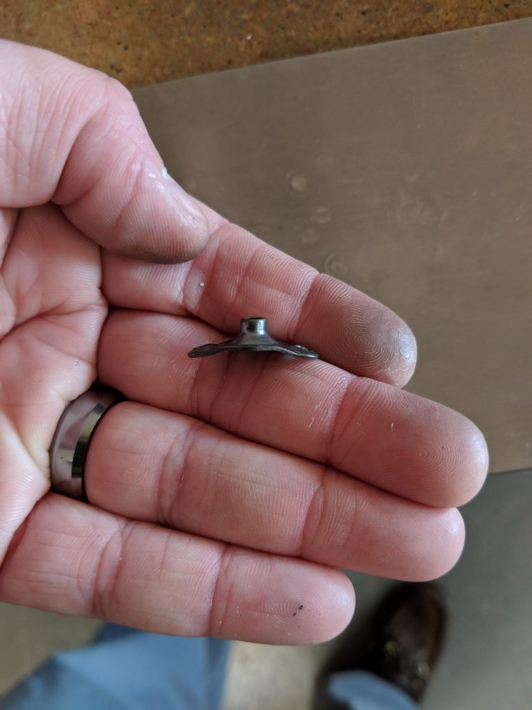
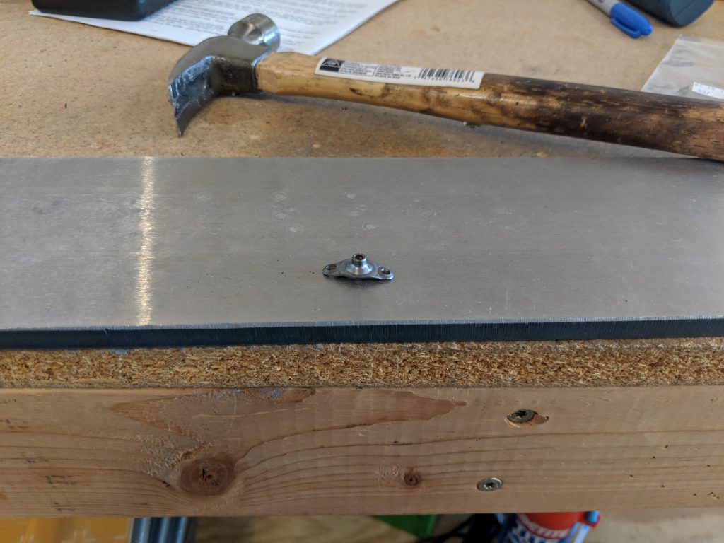
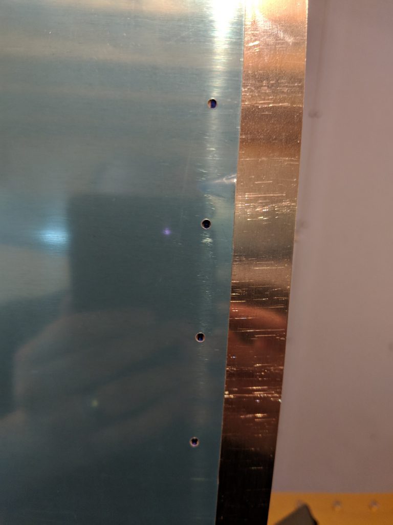
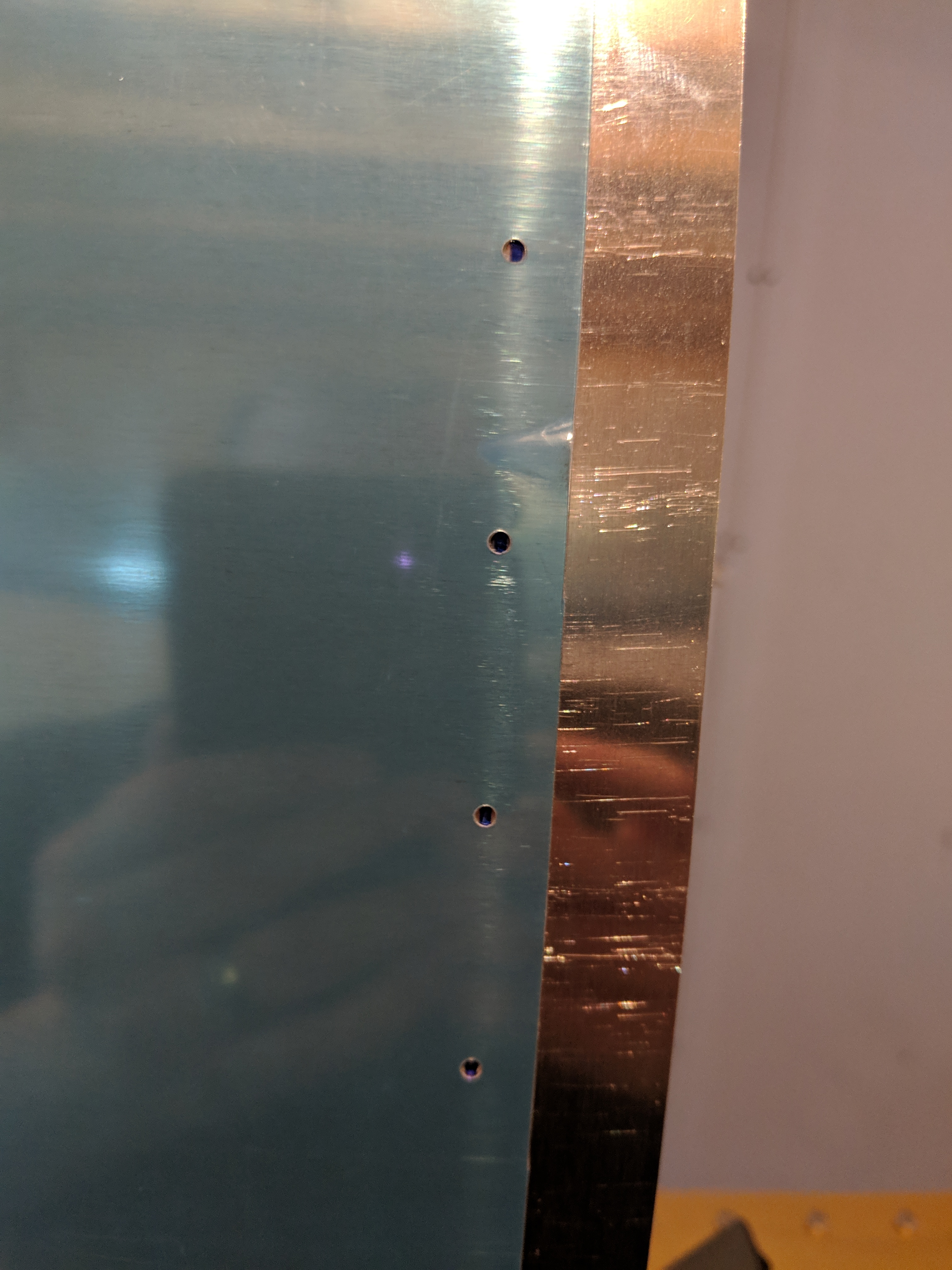
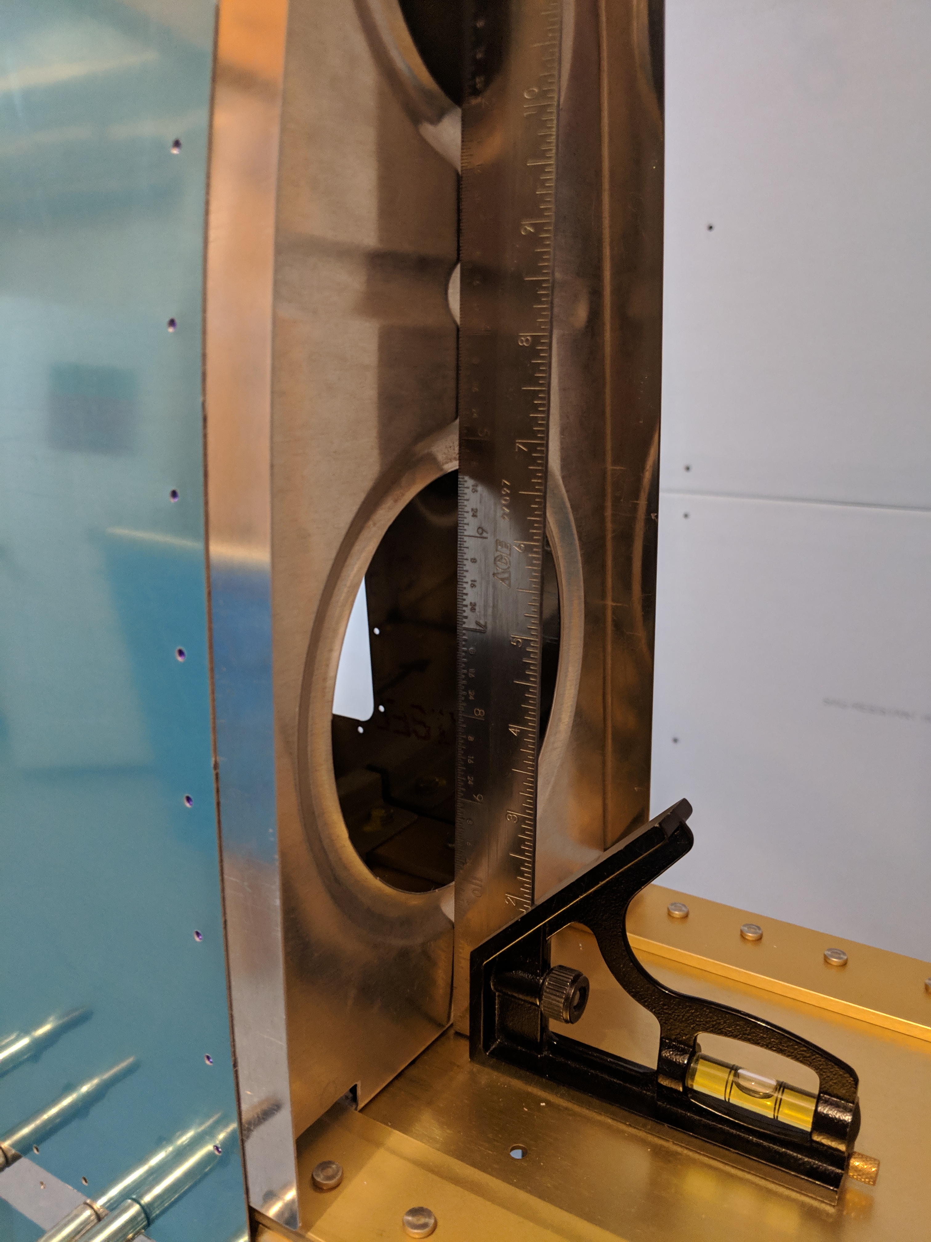
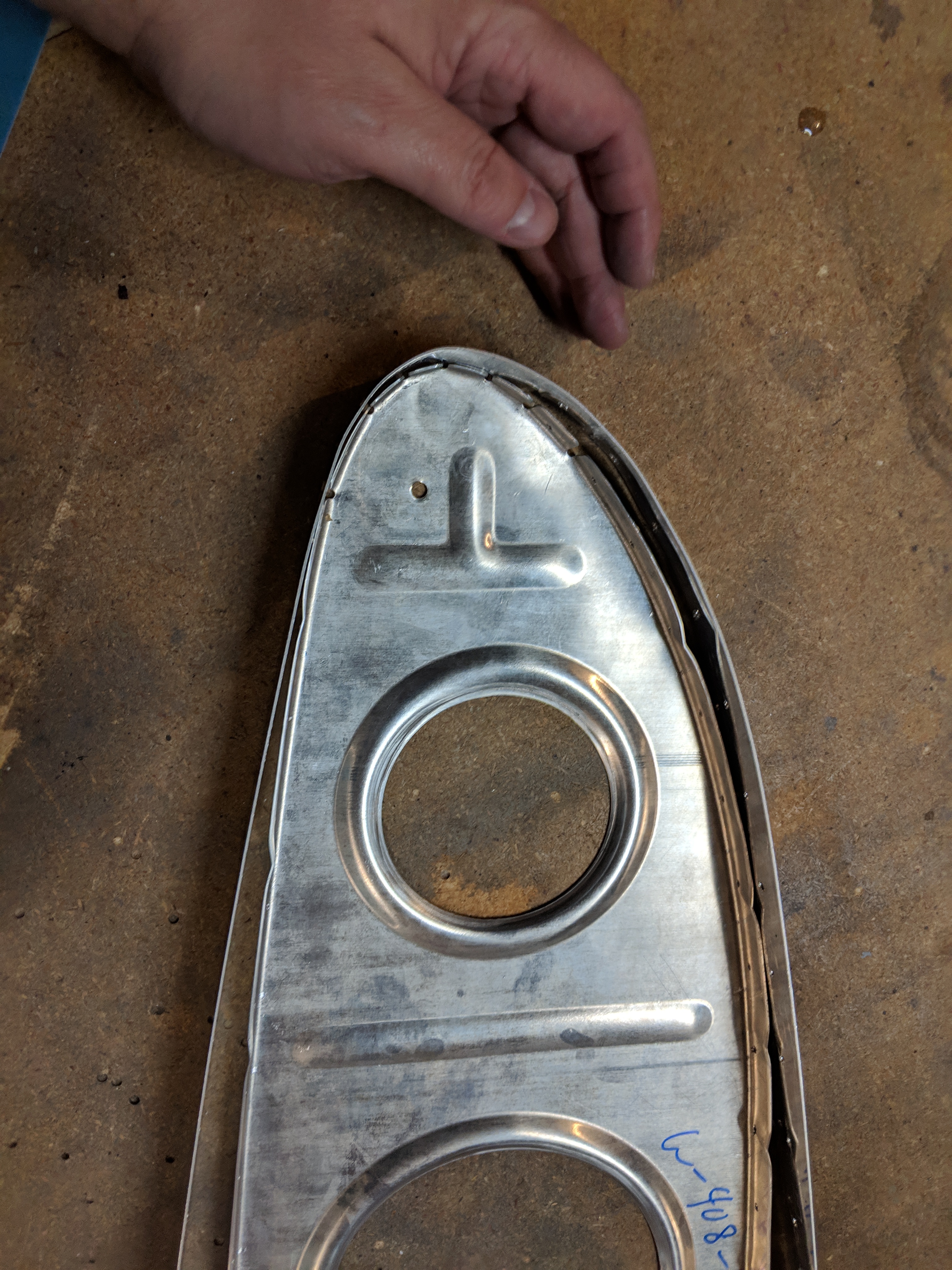
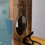
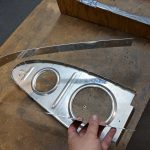
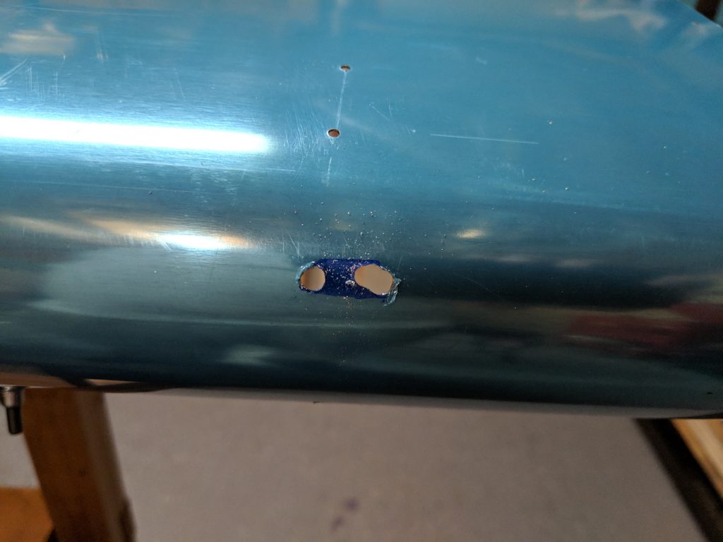
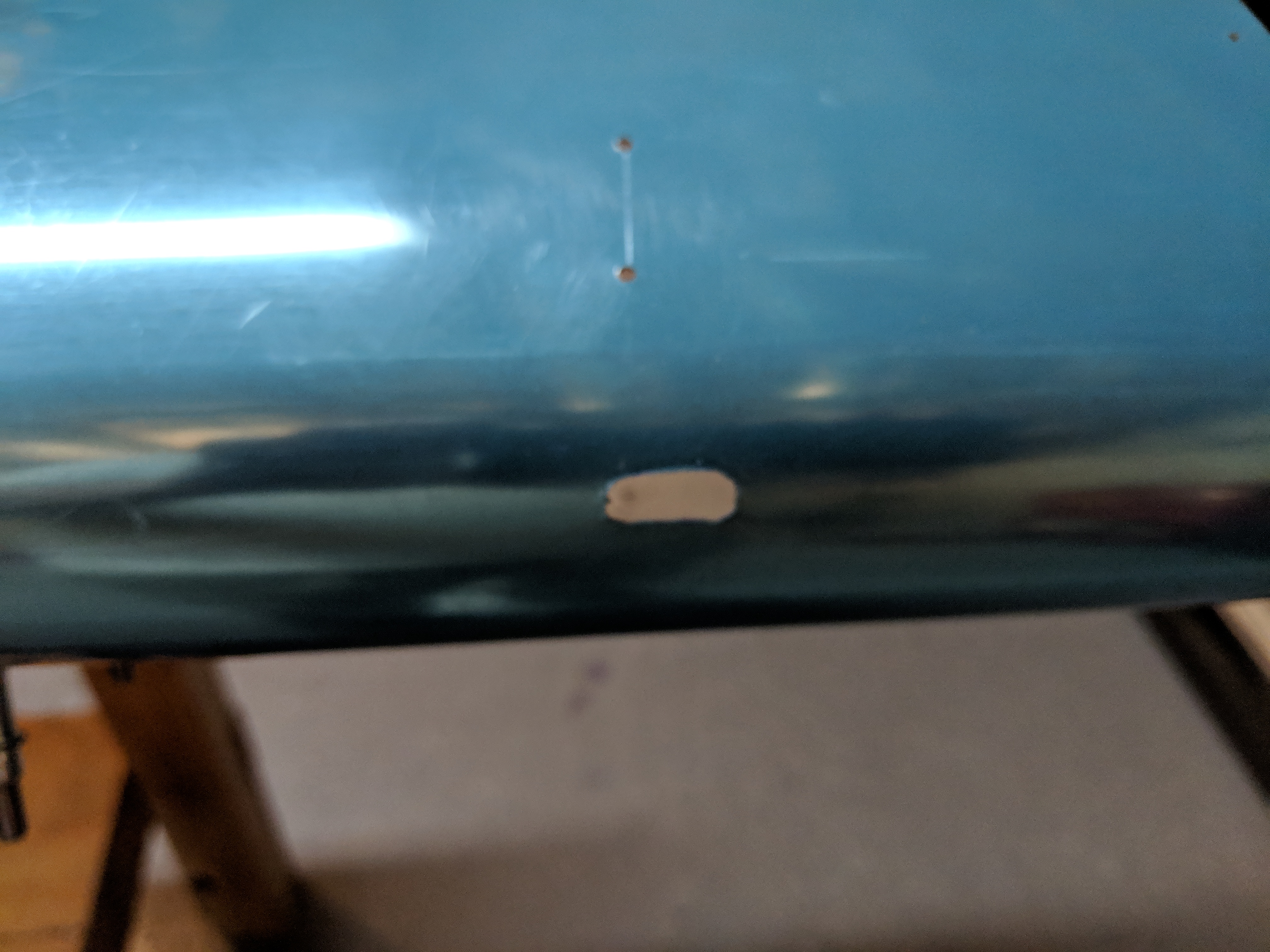
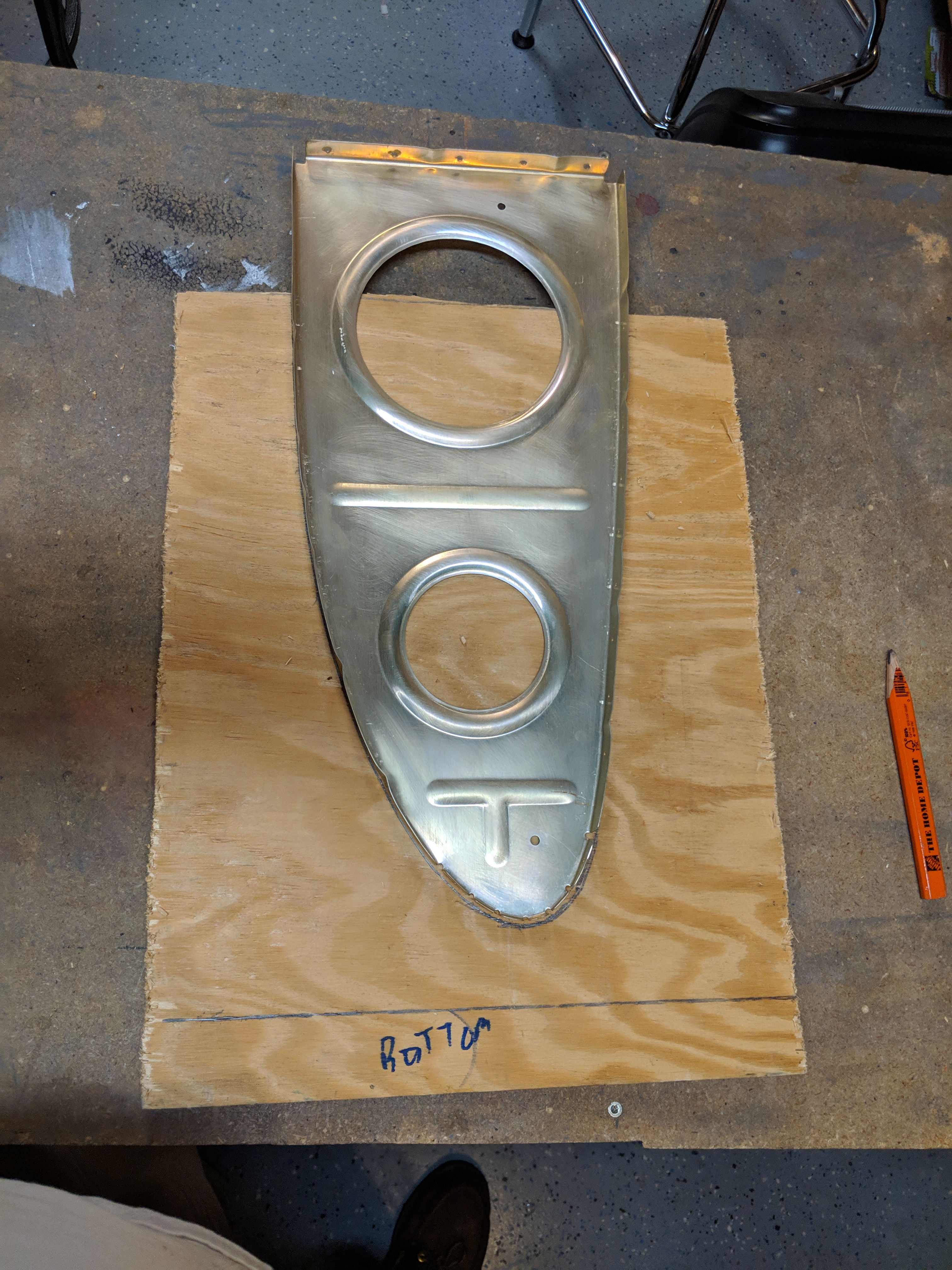
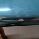
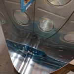
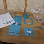
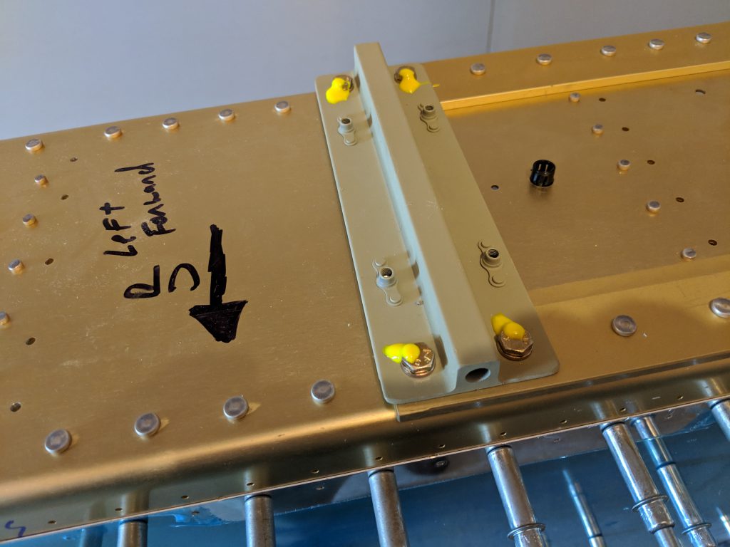
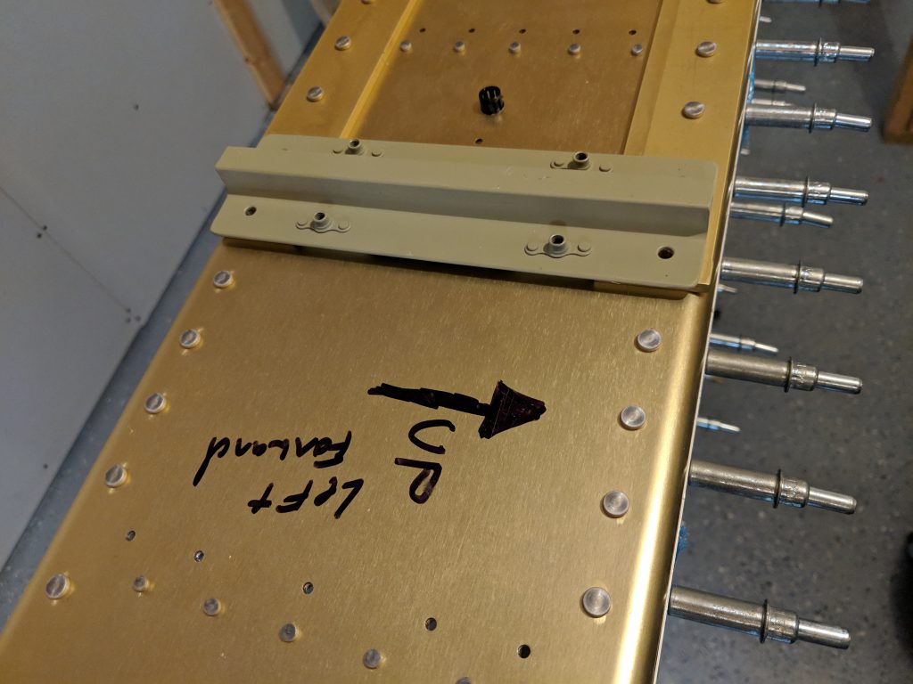
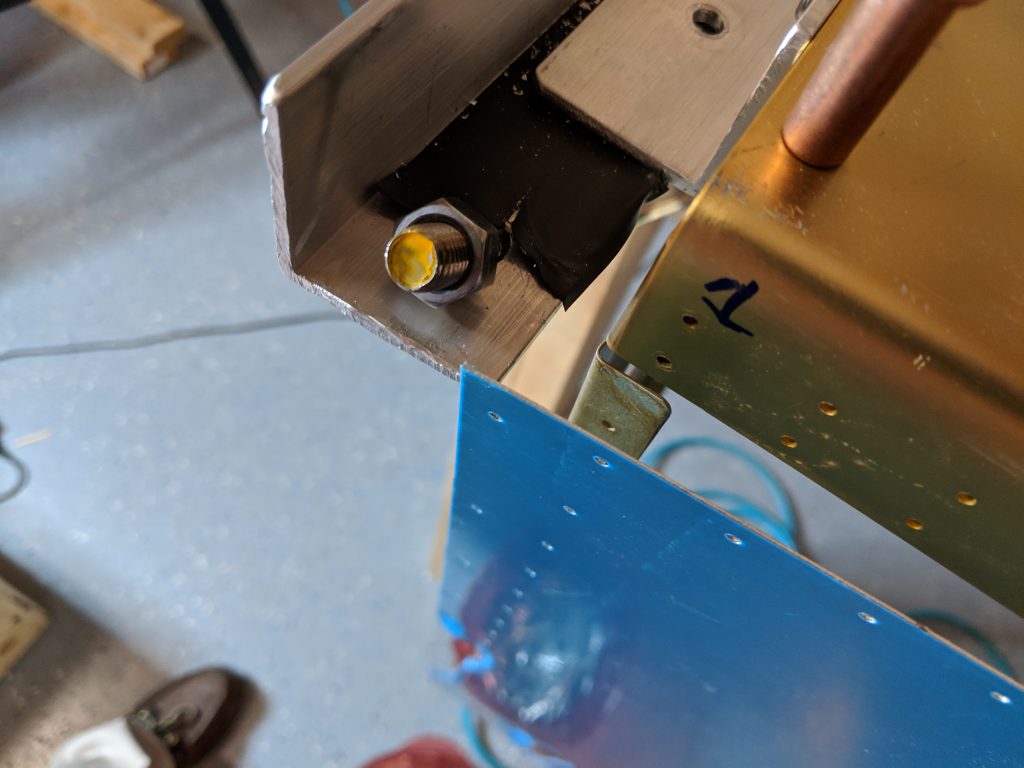
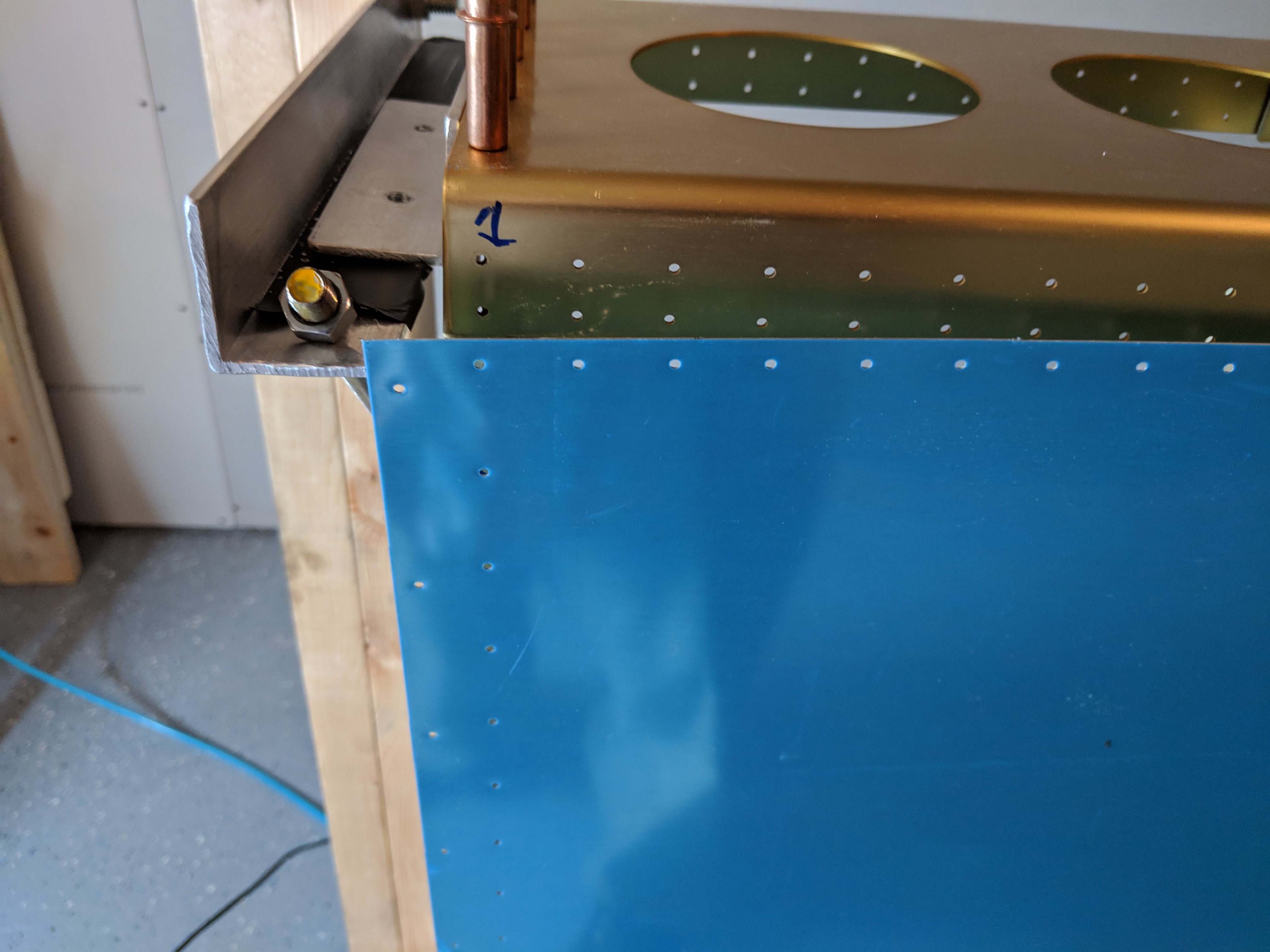
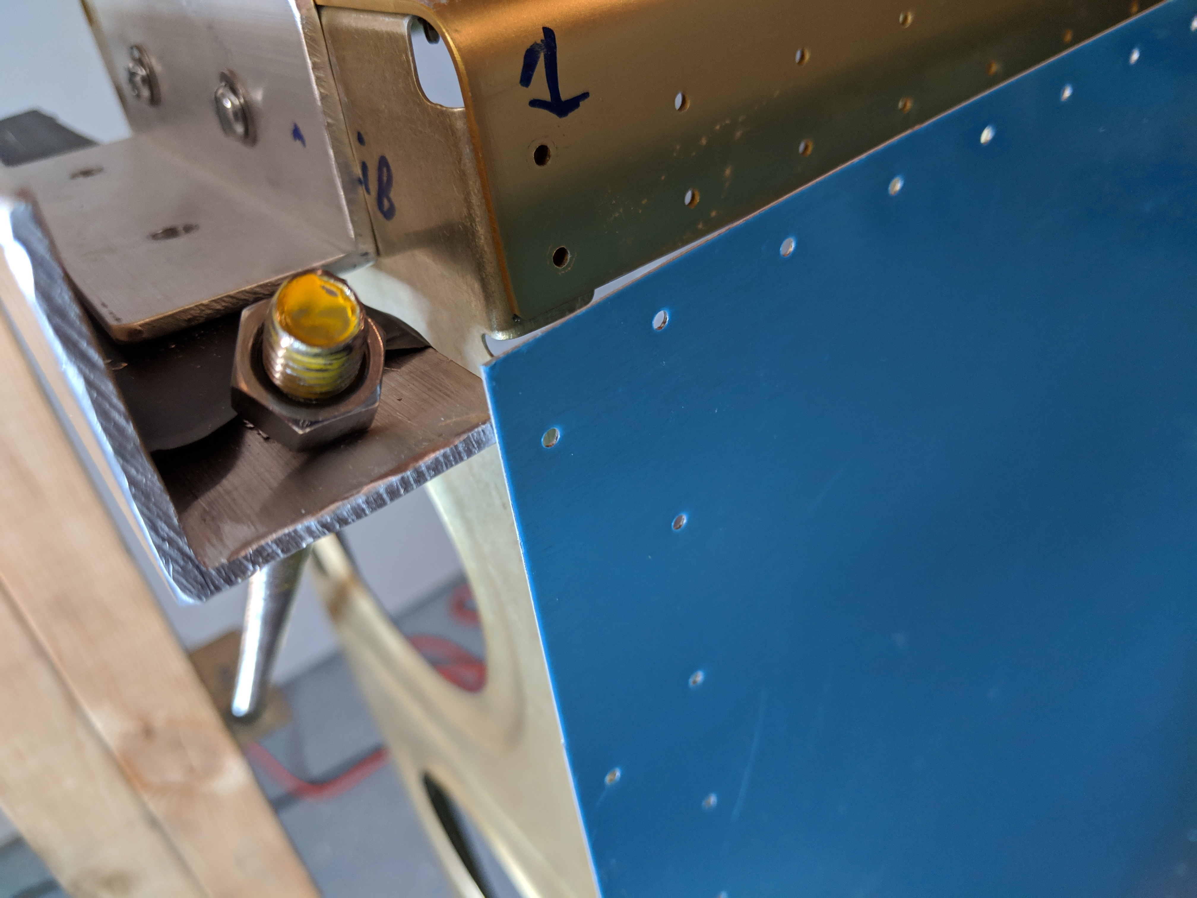
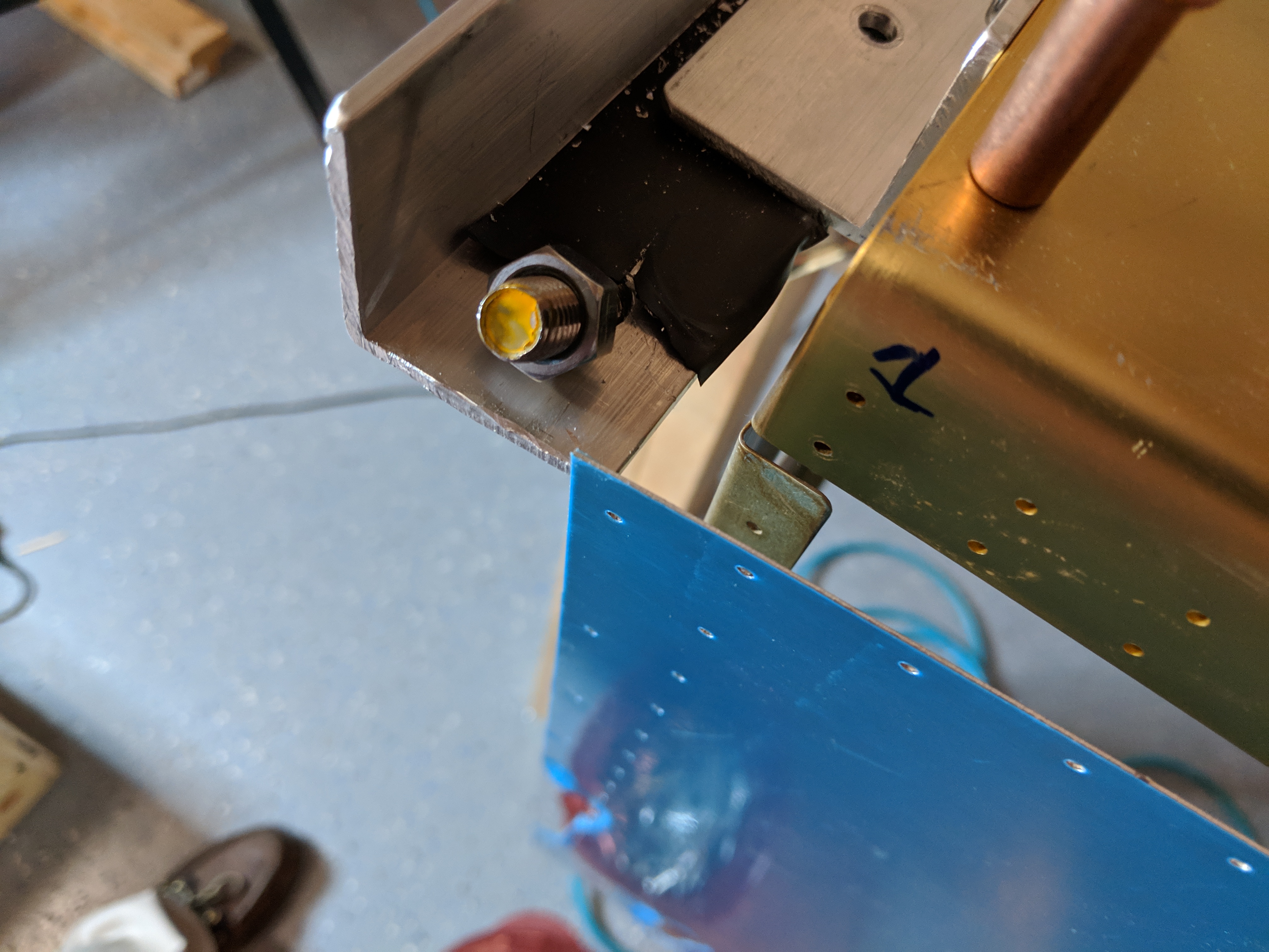
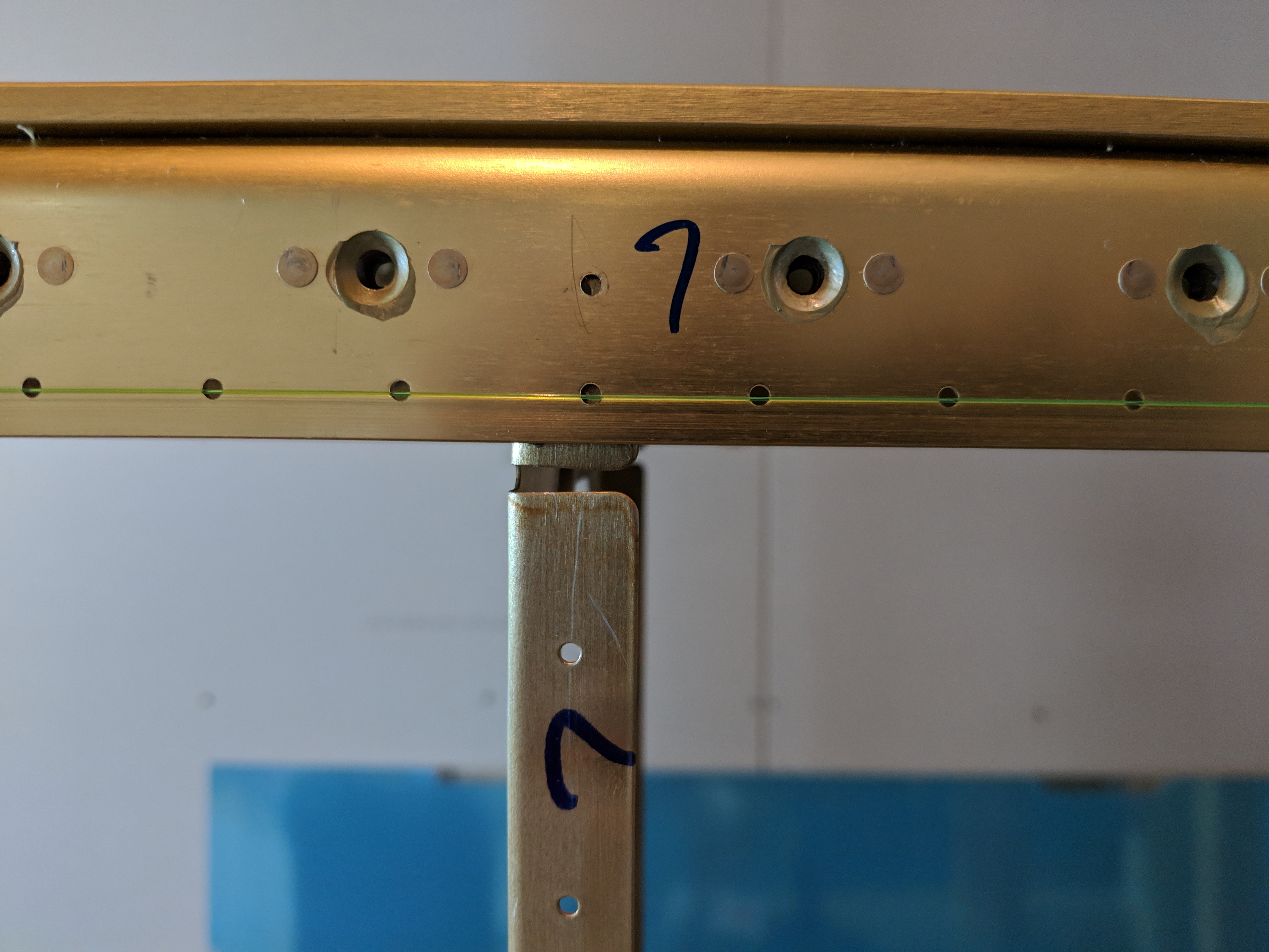
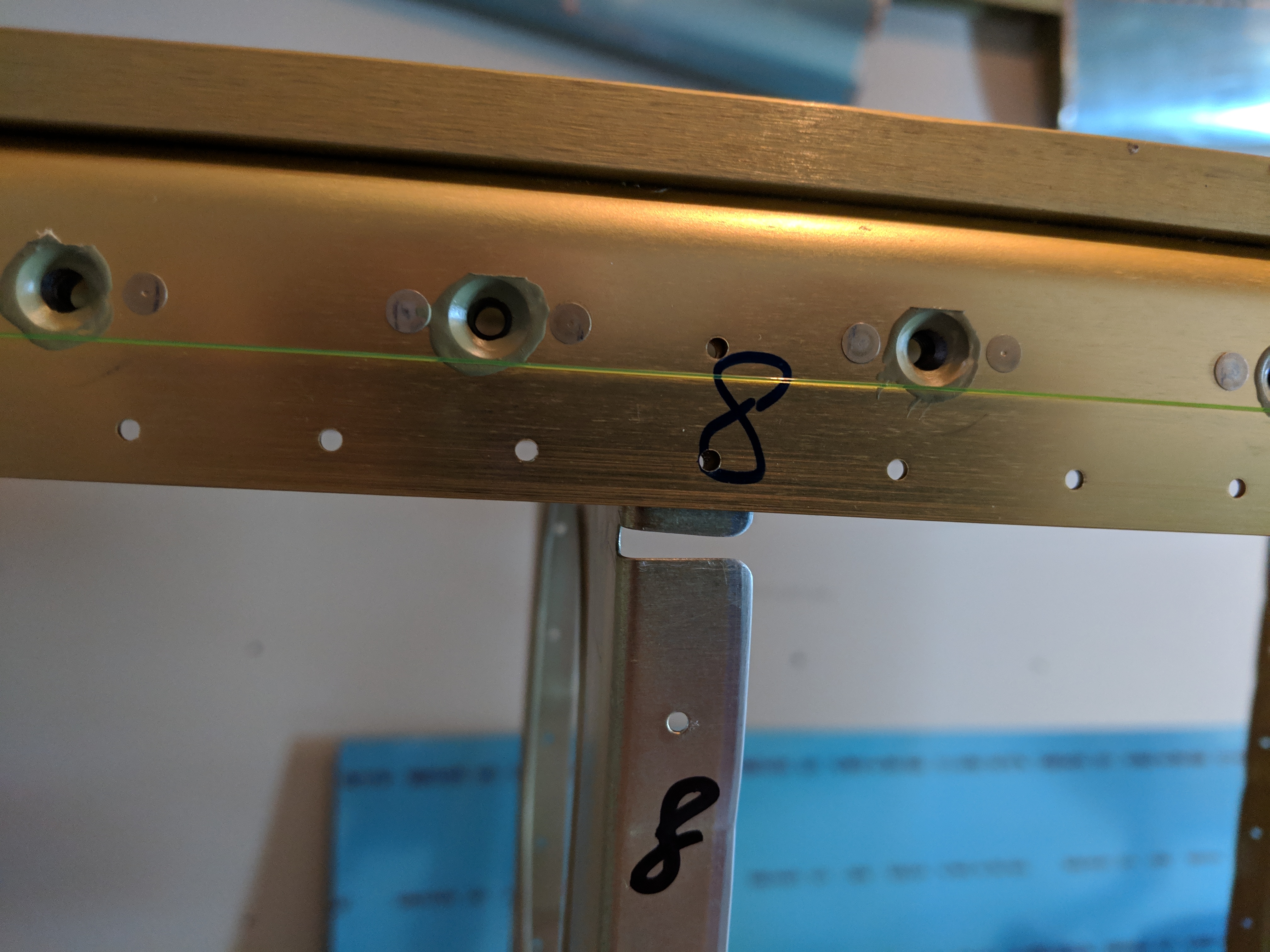
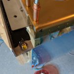
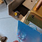
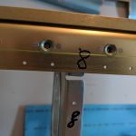
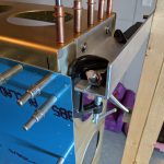
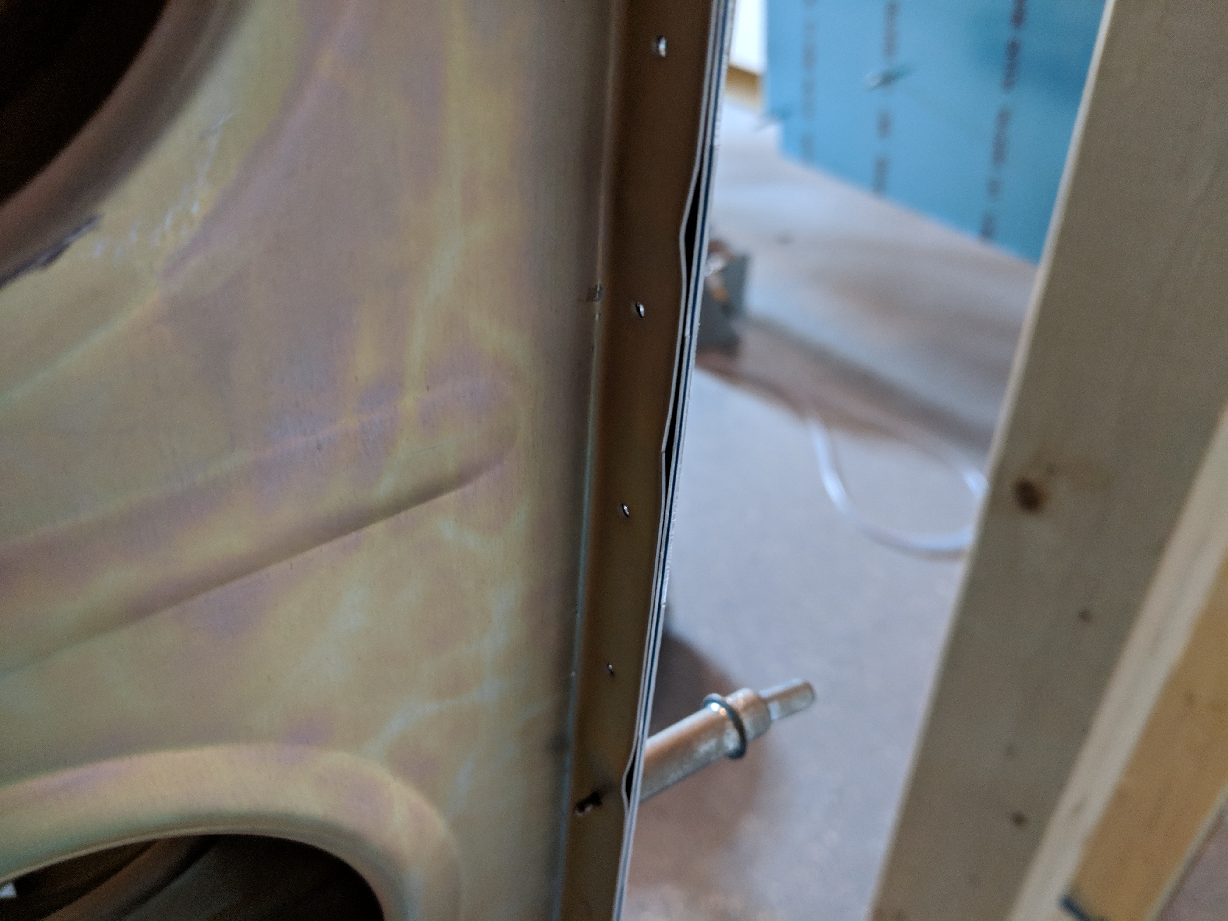
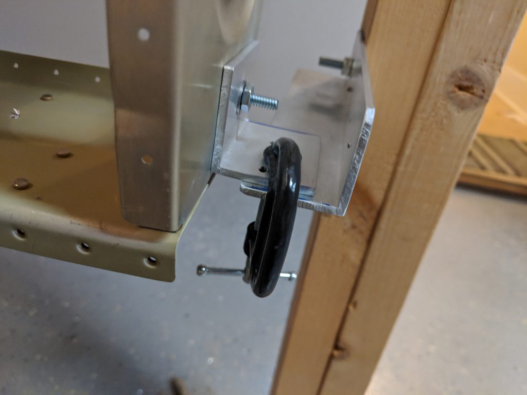
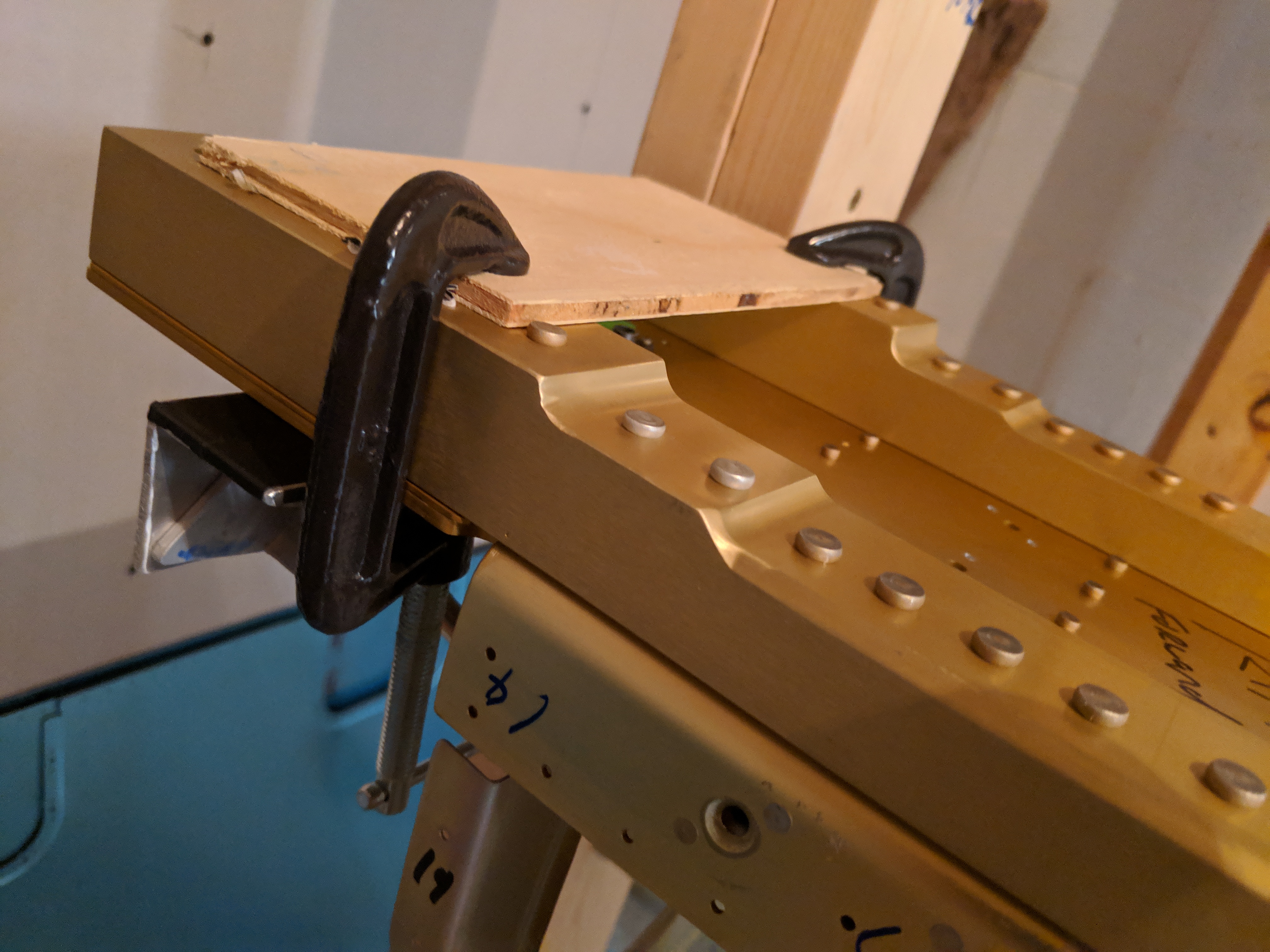
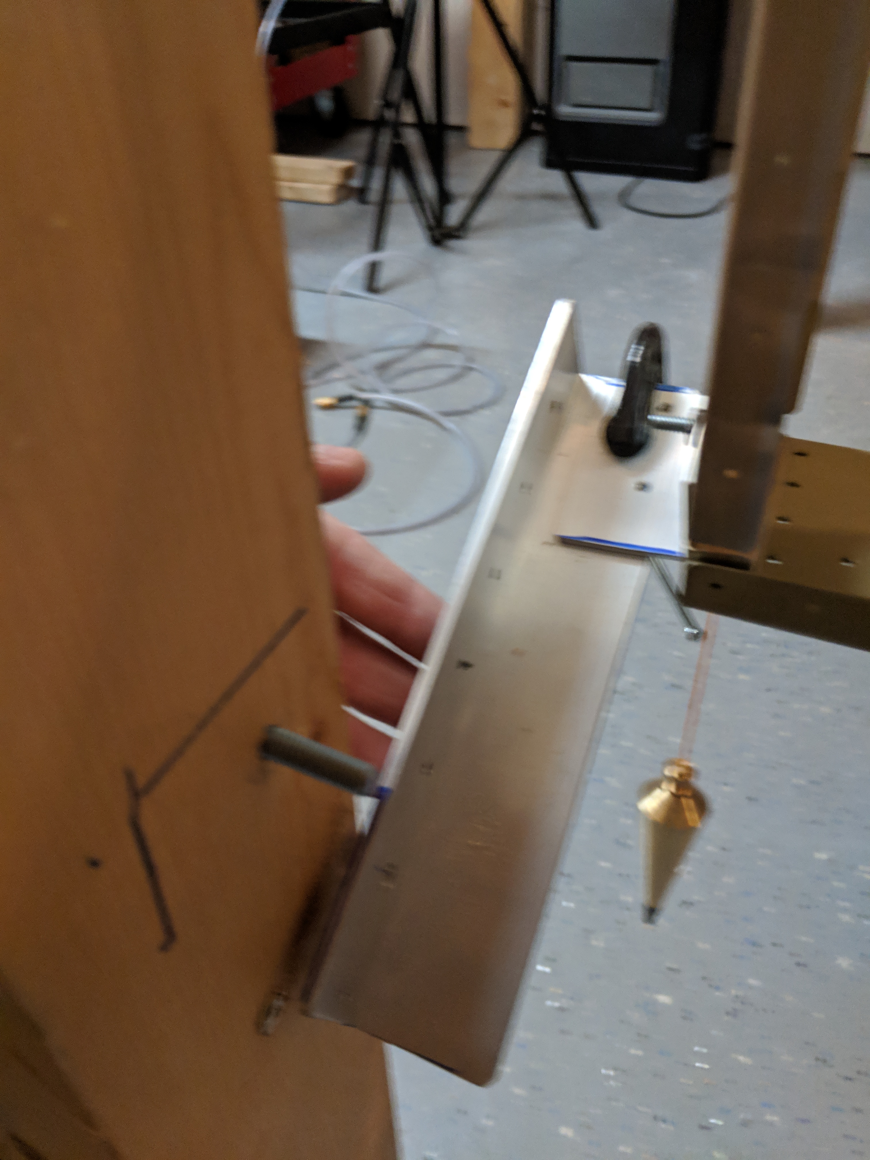
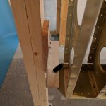
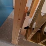
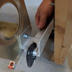
I was obviously wrong.  I drilled all the holes using the skin as my guide and was thinking everything would be perfect, because I measured this thing a thousand times and has that 11/16″ perfect at each hole.  I was SO SURE this rib was lined up.  So I took the rib and joint plate out to check my work:

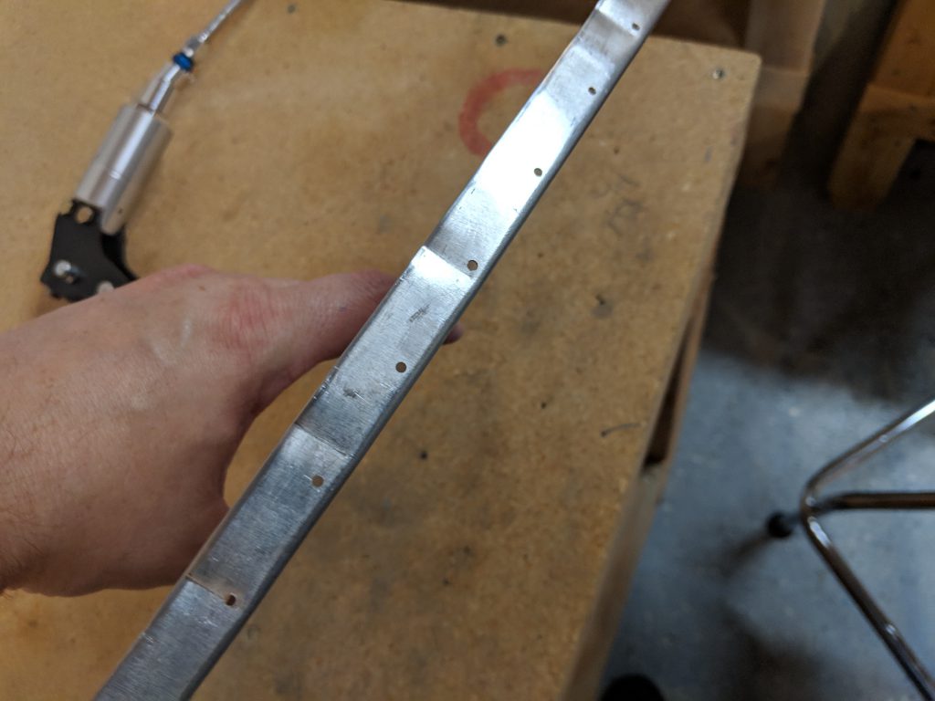
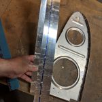
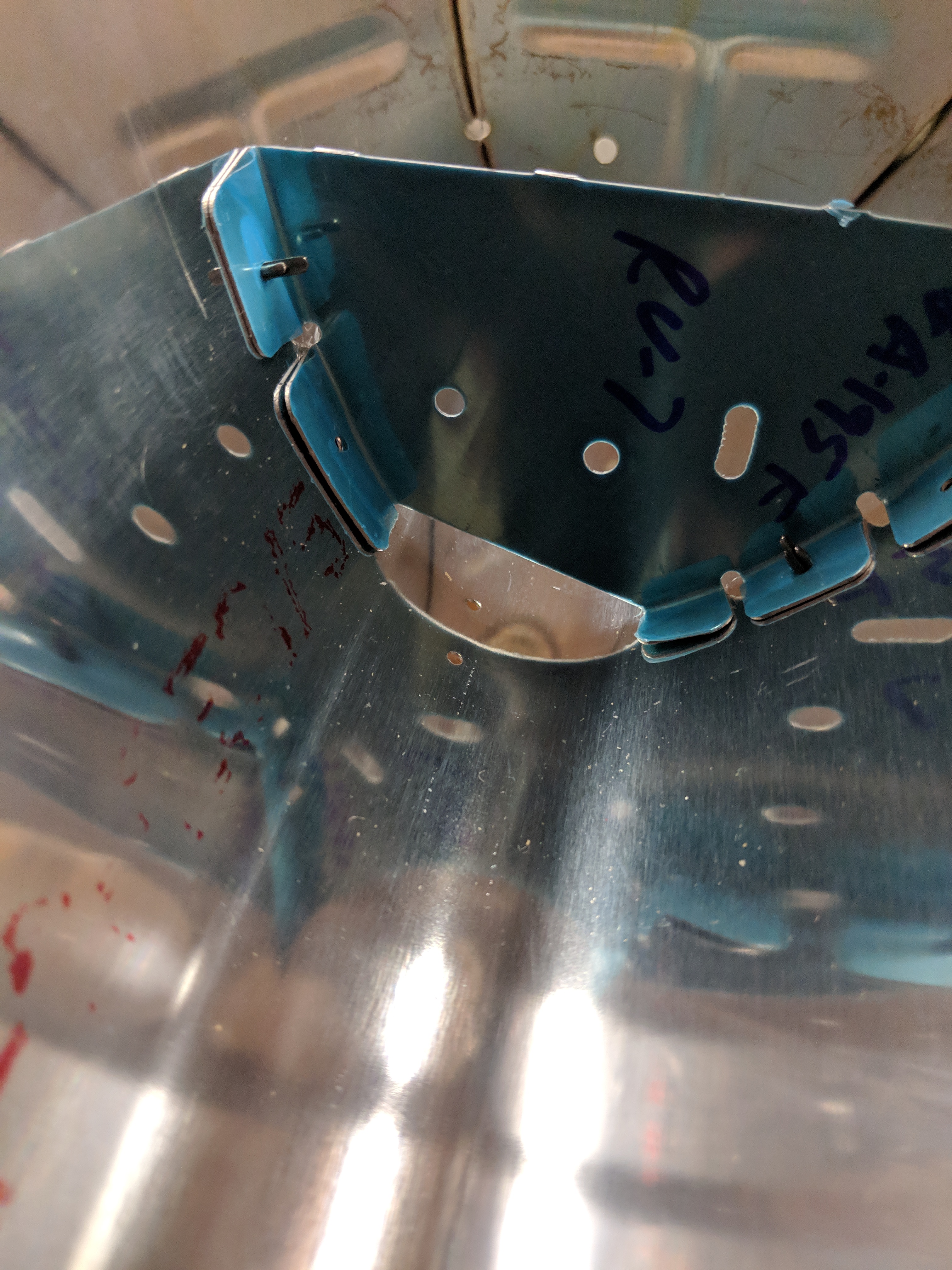
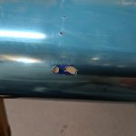
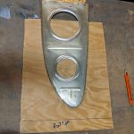
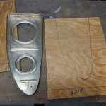
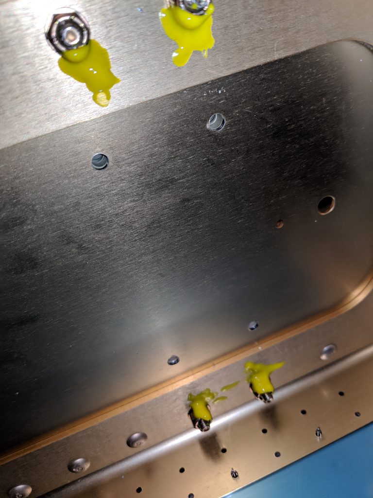
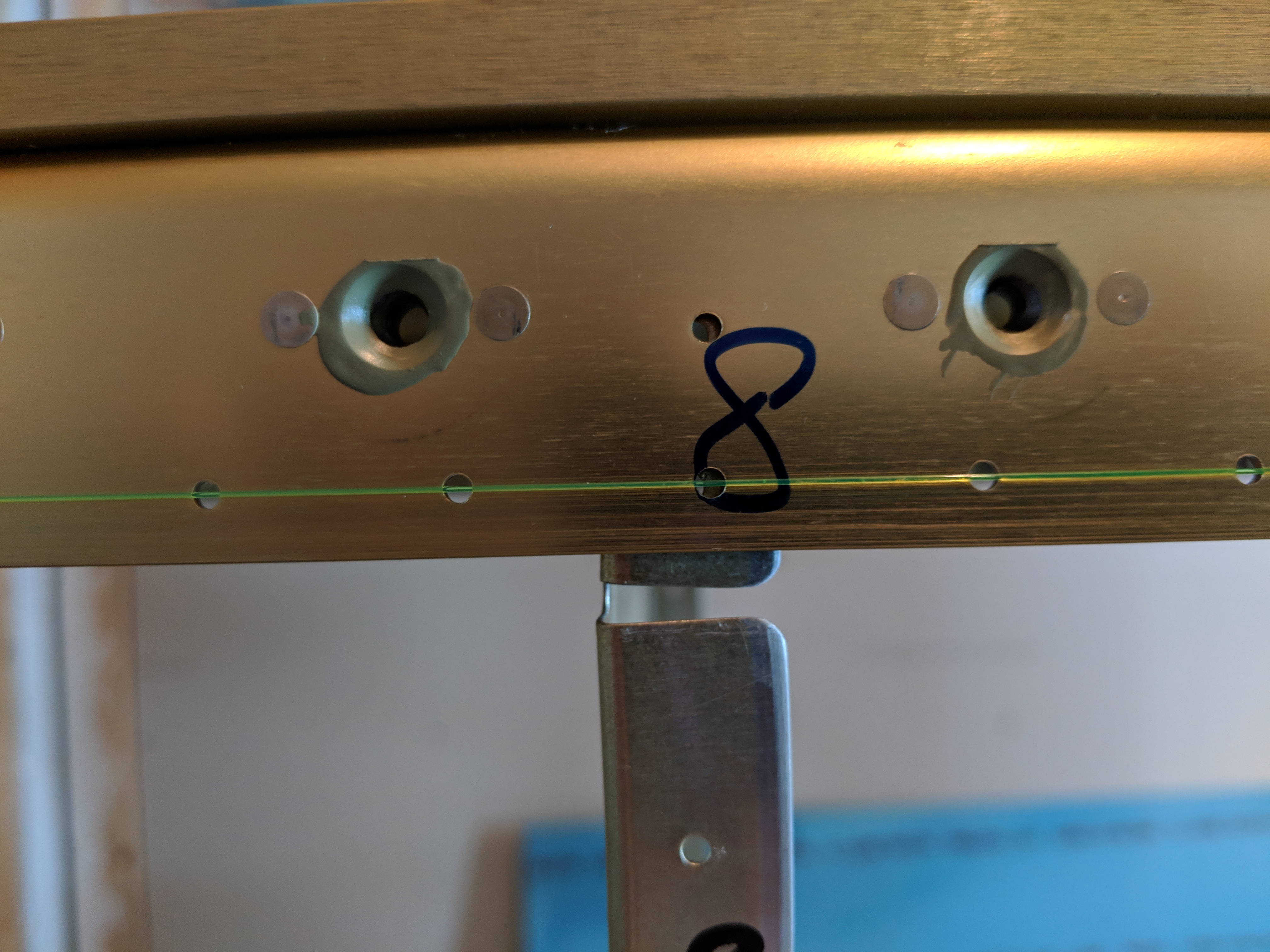
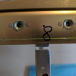
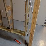
And there it is…. WAY TOOO CLOSE.  I thought to myself…”This is exactly the way I did the left rib, so let me make sure I didn’t mess it up too”. And sure enough, I messed it up too:

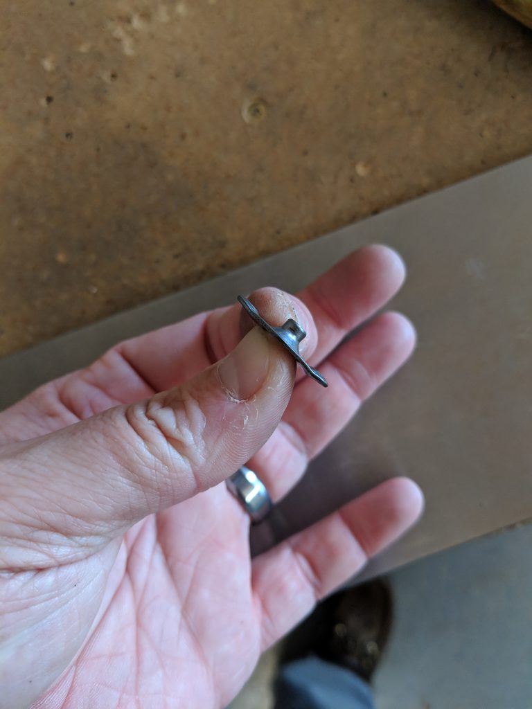
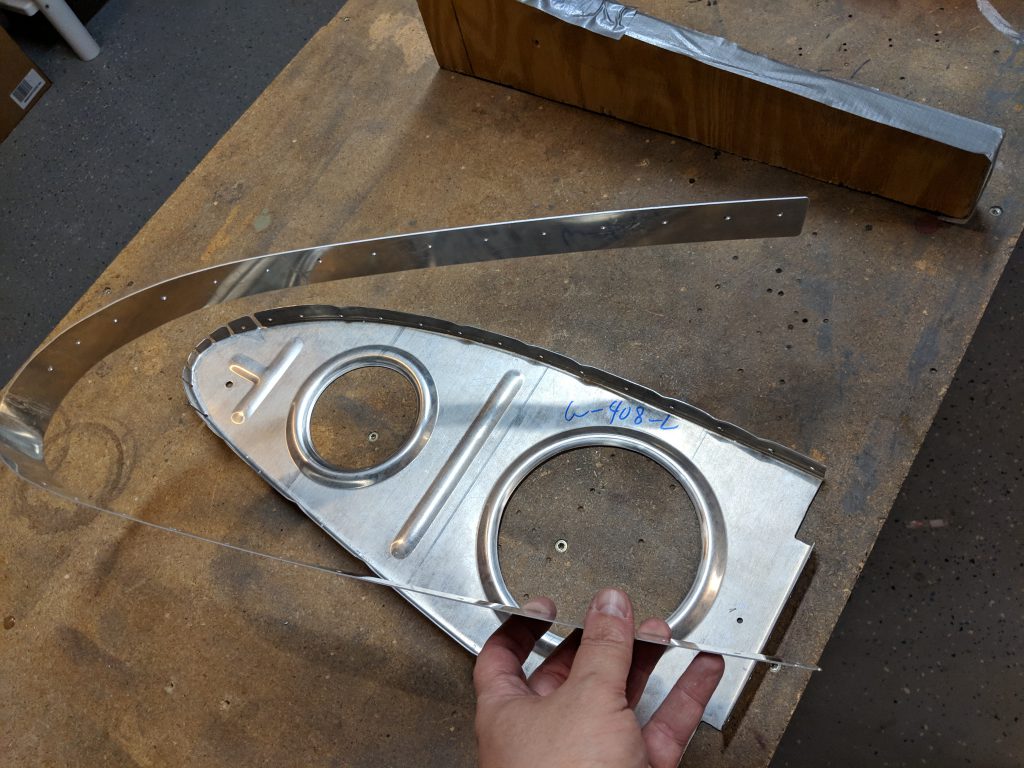
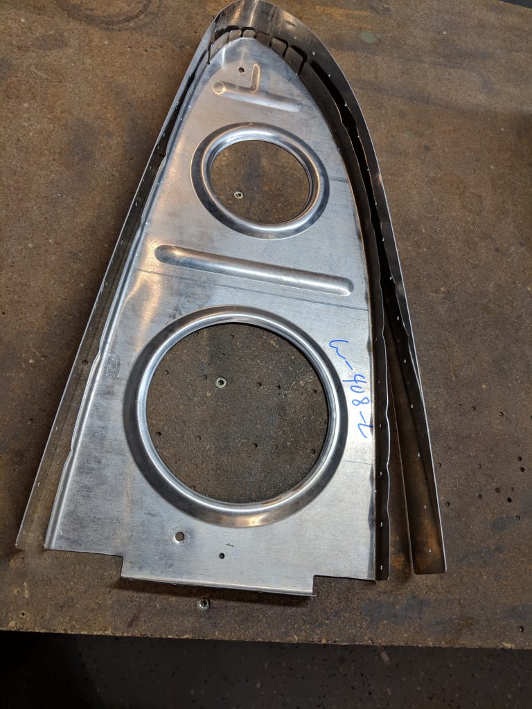
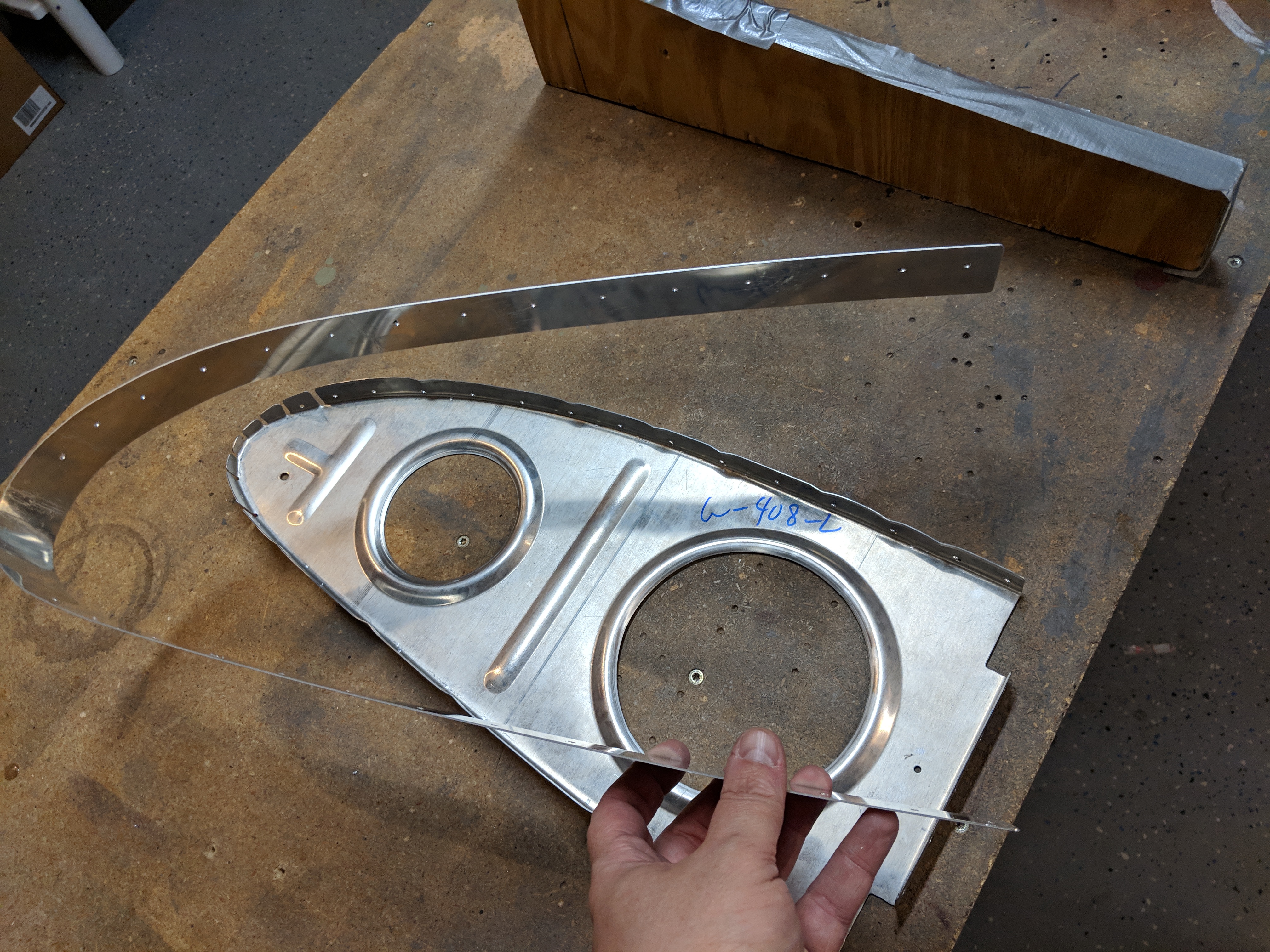
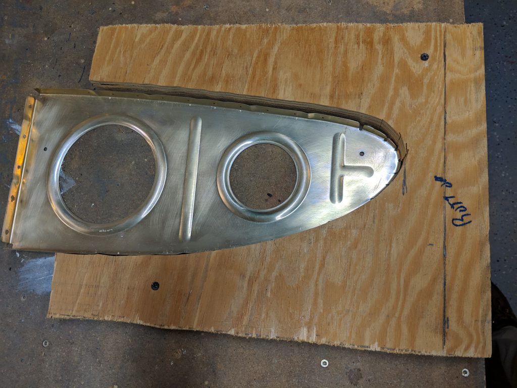
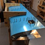
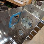
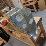
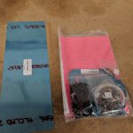
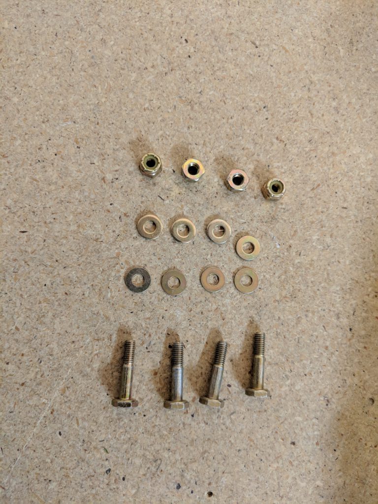
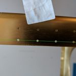
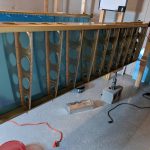
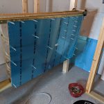
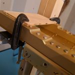
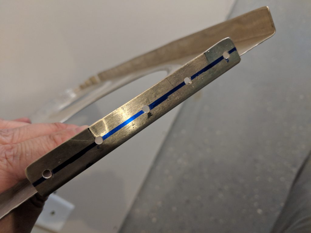
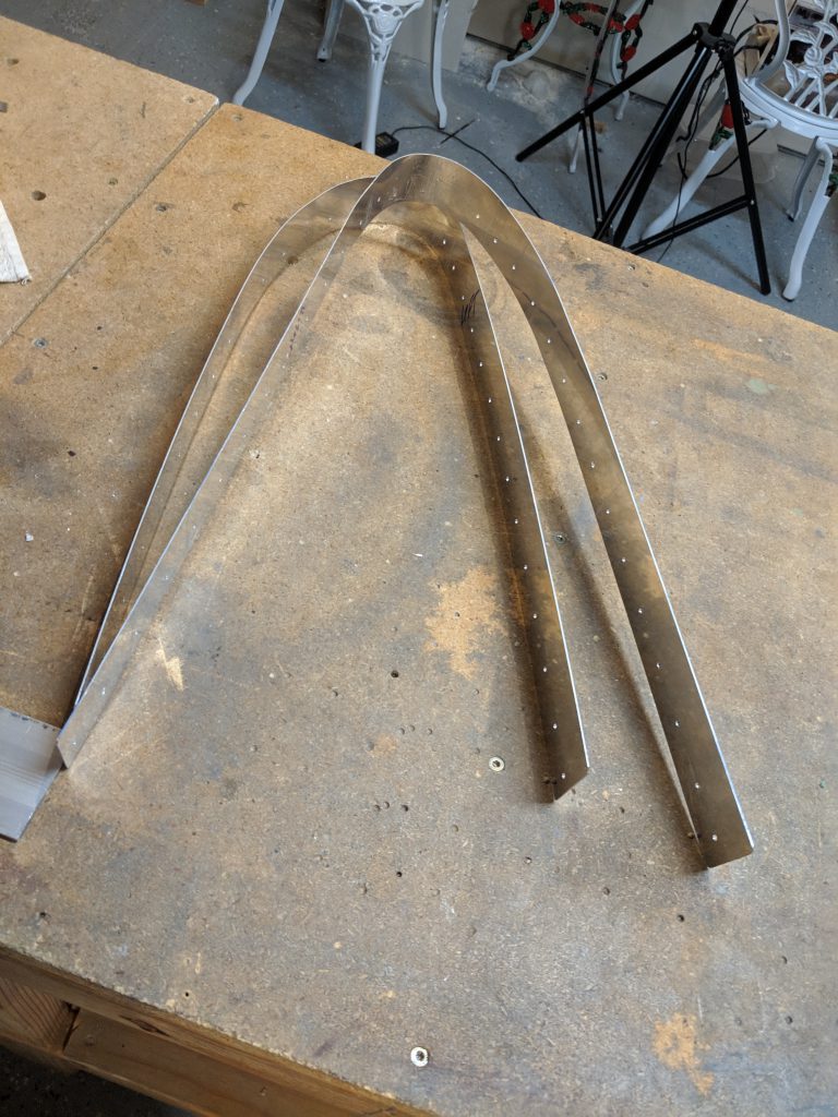
Oh well.  Thank goodness these are only about $28 bucks from Vans and I am still able to replace them.  It was at this point, I decided to call it quits for the night.  I still need to match drill the right leading edge, but I’ll leave that for another session.  The next step is the fuel tanks, so I need to place an order for some proseal, and other goodies, so I’ll toss in two new W-408 ribs to replace these ones.  I am thinking it may be easier next time to get this right, since the joint plate has its holes.  I can just mark the centerline on the new ribs, line them up the holes in the joint plate and skin and match drill.  The joint plates turned out pretty nice, and they even look like a leading edge:

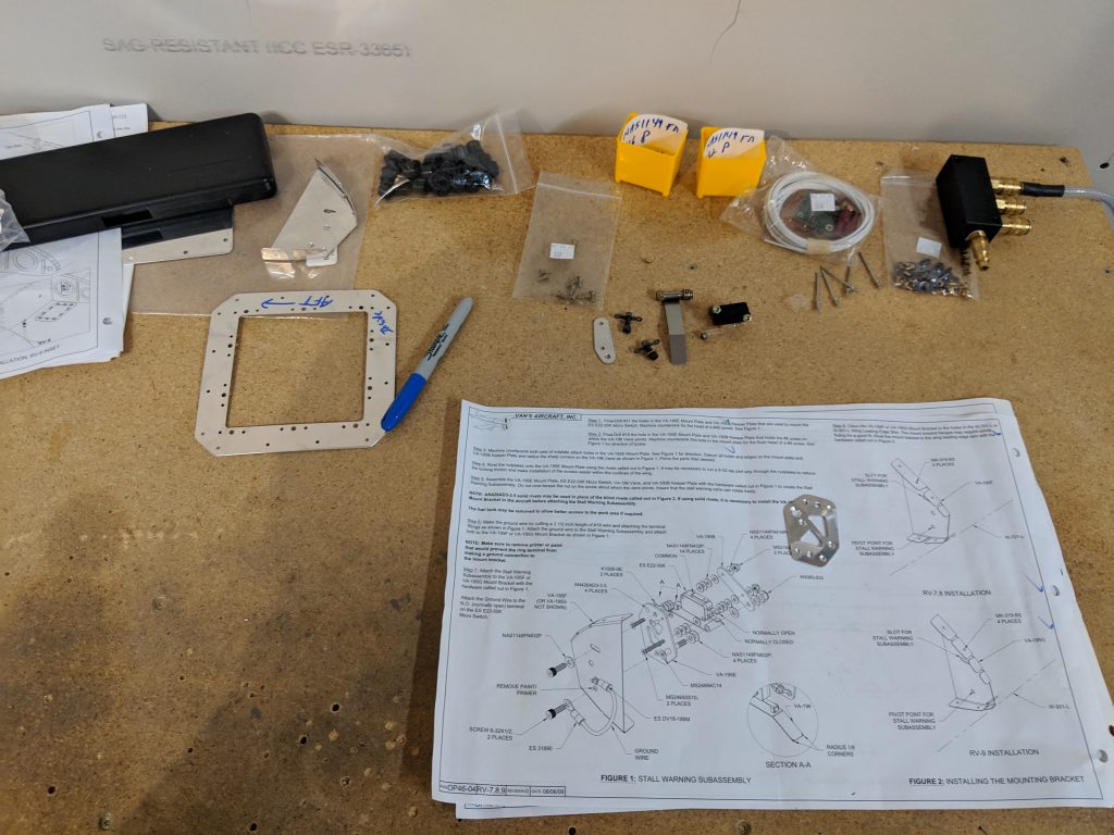
Time to spend some money I guess.  I’ll probably order some sealant, conduit, new W-408 ribs, and see if I can find a good aviation grade crimper set.  My “mistakes” pile is growing 🙂  Thankfully its still much smaller than my pile of completed parts.

Google Photos Link: https://photos.app.goo.gl/wMDxjsoBsiXhjxBX9

Hours Worked: 2.75

Assembling the Stall Warner

I wanted to knock something out tonight since it’s been a while since I last worked on the plane.  So, I figured it was time to finish the stall warner.  I had alodined all the parts to it previously, to help prevent corrosion, but I did not get any photos.  Tonight, I finished building it, all except the electrical connections.  I need to order a good set of crimpers. The session started out by dimpling the nut plates.  I’ve read a bunch on the best way to do this, but theres really no good way.  They are gonna warp regardless.  So I dimpled them in my DRDT-2.

Sure enough, the warped.  But it a little tappy-tap-tap with a small hammer on the back rivet plate and they flattened right back out.

With that bit of detail worked out, I moved on to assembling all those tiny washers, nuts and bolts into an assembly.  This was a fiddly operation, but actually quite fun.  This is the sort of building I enjoy, and its a good break from the monotony of the wings.  The little switch is pretty straight forward, I just had to make sure I had the right washers and the right number of them in the correct spots as called out in the plans.  Then tightened  down the lock nuts just enough so that the actuator worked nice and free, but not sloppy.

It turned out pretty great!

I am not 100% done with it yet.  I still need to make up the 3″ pigtail for the electrical connector and crimp on the terminal, but I am going to wait until I get a good set of aviation grade crimpers to do the job.  Not my cheap, autozone jobbers.  So, I put this assembly away in a little tub, and decided to remove the plastic from the right leading edge, before calling it a night.

Thats it for tonight. Heres a  Google Photos Link: https://photos.app.goo.gl/KH9jBunbivXv7s3H7

Hours Worked: .75

Pre-assembling the Stall Warner

I decided to tackle some small things tonight – The stall warner.  I have been looking forward to this for a while now, because it looks a bit intricate (a nice break from the monotony of the wings!), and includes a little electrical work.  The first step was to open the parts bags and sort all the bits, pieces, nuts and bolts! There was a lot of tiny washers, and nuts to sort. Thankfully I was not missing anything, I did not inventory this kit when I received my wings.  Not sure why I didn’t, but I would recommend that you do.

The first thing I needed to do was deburr all the holes and edges in the inspection plate cover and its doubler.  I removed all the blue plastic, deburred the holes on each and then smoothed the edges down.  The plans tell us to go ahead and rivet the nut plates on now, but I think I am going to wait and do that AFTER I alodine all these parts together in a batch, so I set it aside for now.  Following that, I removed all the plastic from the small brackets and deburred the edges on the scotchbrite wheel for each one to make it easier to work with.  I also rounded the corners of the stall warner vane as per the plans.  I think its stainless? So it was a bit more difficult than the soft aluminum to work with a bastard file.

Then the plans tell us to double check the layout of the mounting bracket, and then machine countersink the holes where the three screws hold the stall warner switch , as well as the two AN426AD3-3.5 rivet holes that holds two nut plates.  I decided to do this by hand and just use the screws as my depth guide checking every now and then again until I had removed enough material for them to sit flush. Here’s how it came out:

Now comes the fiddly part.  I spent some time with the dial calipers measure the three different sizes of washers to make sure I had them correct, because on the smaller ones, there is only 1/16″ difference in thickness, something my eyes can’t see!  A cheap digital calipers worked great for this.  Now that I had my washers sorted, and my bolts and screws identified, I laid everything out and started assembling it:

Now that I had those spacers looking correct and the stall warner vane setup, I slide the switch itself on and stacked the other side of washers:

Then I laid on the retaining plate and made sure to use the thinner washers where appropriate:

I didn’t want to torque anything down, as I need to alodine the assembly, so I just finger tightened the nuts to make sure I had everything pre-assembled correctly. The whole assembly came together really nicely, and its a very simple and robust design.  It uses machine screws with hex heads going into nutplates to hold it to the leading edge assembly, so it should be easily removed from the leading edge via the inspection plate if maintenance is ever needed on it.   The entire assembly would slide right out, very clever!

Once I was happy I had all the parts in the proper places, I slowly disassembled the unit and made sure to remove the thinner washers (there’s only 4 of them) and put them in a separate and labeled container to save time on final assembly.  The rest, I stuck on the bolts and finger tightened the nuts on the bolts/screws to retain everything.  Then I set it all out on the bench for tomorrow.  I plan on dimpling and then alodining the aluminum parts tomorrow night, so they will have some decent corrosion protection. I may even spray them with some AKZO just to be safe, since they will get wet from the slot on the leading edge.  Heres a shot of all the parts laid out and somewhat organized 🙂

Google Photos Link: https://photos.app.goo.gl/1XQjmuetywXxaY5XA

Hours Worked: 1.5 Hours

Fitting the Left Leading Edge

It’s starting to look like a wing! Tonight, I decided to get the leading edge fit to the left wing to get an idea of what all was involved.  When I left off last time, the leading edge was loosely put together in the cradle, so thats where I started.  I first matched drilled all the holes for the stall warner access cover doubler and the stall warner mounting bracket (that goes in the leading edge) to the proper #40 hole, then removed it and put it on the bench.  I’ll do the assembly of it after I get the leading edge on the wing so I can have more working room.   I had a little helper helping with the stall warner:

Next up, was to get the leading edge on the wing, and clecoed into place, which went smoothly.  I clecoed all the ribs from the aft side of the main spar, and the clecoed the aft edges of the skin to the spar.  It fit really nicely, and its looking close to a wing!

Now, this is where it gets a bit…..fiddly.  The W-408-L wib is NOT pre-punched, so we have to back drill it using the skin and the spar as a guide.  In addition, we have to fit a W-723 joint plate sandwiched between the W-408-L rib and the leading edge skin.  Here’s the fiddly bit:  The W-723 joint plate is nothing more than a piece of AS3-032 sheet pre-cut to 1.5″x36.5″.  Which is nice, because its cut to the exact dimensions, but I had to bend and mold it into the shape of a leading edge. Before I went about bending it, the plans tell us to draw a line 1/2″ from one edge. This is the line we will use to help line the joint plate with the pre-punched holes in the skin.

The photos above, you can see where I have already drilled it, thats because I didn’t get any photos of me bending it. I will on the right wing 🙂 . But, once we had all these pieces sort jammed together on the leading edge, I double checked all the clearances, and then back drilled the aft flanges of the rib to the main spar, and clecoed it securely.  Next, I made sure my blue sharpie line was lined up correctly in the leading edge skin holes and then double checked the rib was straight with a square.

I started at the aft edge, and back drilled a #40 hole using the skins holes as a guide, then clecoed it.  I skipped a few holes and drilled another and clecoed to help make sure nothing was moving.  I kept doing this until I had everything back drilled.

Once I had everything back drilled, the only thing left to do on the leading edge was to match drill all the holes in it.  So, I chucked up a #40 reamer and reamed all the holes (ribs, spar, etc) to the proper size, then moved my clecos, and reamed those holes.  Eventually, I had all the holes reamed, but there were a few that needed back drilled at the front of the leading edge, so I used a #40 drill bit on those, and marked them so I would remember to deburr them. That finished up this session, and I think I will work on assembling the stall warner completely, getting it test mounted, and then open up the hole in the leading edge skin for the tiedown. Here’s all the photo from tonights work:

  • IMG_20190227_225610
    IMG_20190227_225610
  • IMG_20190227_213548
    IMG_20190227_213548
  • IMG_20190227_213600
    IMG_20190227_213600
  • IMG_20190227_213604
    IMG_20190227_213604
  • IMG_20190227_213609
    IMG_20190227_213609
  • IMG_20190227_213614
    IMG_20190227_213614
  • IMG_20190227_213617
    IMG_20190227_213617
  • IMG_20190227_223903
    IMG_20190227_223903
  • IMG_20190227_223911
    IMG_20190227_223911
  • IMG_20190227_223915
    IMG_20190227_223915
  • IMG_20190227_223921
    IMG_20190227_223921
  • IMG_20190227_223926
    IMG_20190227_223926
  • IMG_20190227_223933
    IMG_20190227_223933
  • IMG_20190227_225053
    IMG_20190227_225053
  • IMG_20190227_225058
    IMG_20190227_225058
  • IMG_20190227_225541
    IMG_20190227_225541
  • IMG_20190227_225546
    IMG_20190227_225546
  • IMG_20190227_225553
    IMG_20190227_225553
  • IMG_20190227_225604
    IMG_20190227_225604

Google Photos Link: https://photos.app.goo.gl/zxEU6f3vWHnQctkE6

Hours Worked: 2.25 Hours

Assembling the Left Leading edge and Stall Warner

I started out tonight assembly by doing some disassembly! I needed to remove the right wings bottom skin per the plans (both bottom skins come off, the left I did last night), and to free up some much needed 3/32″ clecos. I was running pretty low!  This was quick work, I removed both the inboard and outboard bottom skins and tucked them safely out of the way for now.

The next step was to build the leading edge cradle, to make assembling the leading edge and tanks much easier.  I built them pretty much to Vans specs, and used a W-709 leading edge rib as a template for where to cut:

I only traced the line onto one of the cradle supports, they are both the same size.  So, I screwed them together in a sandwich,  so that I’d only need to make one cut on the band saw and they’d be cut exactly the same.  I always say….even though I’m building a metal airplane, I tend to use my woodworking tools a good bit during this build 🙂   The band saw made quick work of the curvy cut, and the rib fits nicely in place, with enough room to put some duct tape or foam for cushioning and to keep from scratching the skin.

Then I cut a 2×6 to 26″ in length and screwed the cradle supports into it using some 3″ construction screws (yeah, a bit overboard on the 3″ but they were some I had laying around extra).  I’m pretty happy with the way they turned out.  After the photo below, I put some duct tape on the inside edges of the cradle to protect the skins a bit. I’ll make the second cradle once I need it, which will probably be the tanks.

Reading the instructions, Vans has us remove the plastic from the inside of the W-701-L wing skin, and put it in the newly made cradle to make assembling the ribs a bit easier.  It’s starting to feel like I am actually building again 🙂

Once I got the plastic removed from the inside of the skin, and put into the cradle, I cleco’ed the ribs into place to help form the leading edge.  A few of these were a bit tight, as I had to sort of bend the skin over a bit to get it to take shape against the leading edge ribs. I did the outermost ribs first, and then worked my way inwards clecoing every other hole.

The next step in the plans tells us to start working on the stall warner kit. This is where the plans gets a little hard to follow, as the RV-7 plans tell us to complete OP46-02 Steps 1-4 and OP46-03 Steps 1-5. These are actually provided in the stall warner sub-kit, which was designed to be installed in all of the different RV models, both during and after construction (in case of a retro-fit on an already-built airplane).

Stall Warner installation kit

Stall Warner installation kit parts on display

I had to read over the entire set of OP46 plans and instructions to get an idea as to what to do, and when to do it . There’s a few pieces of the kit we don’t need since the RV-7’s are now shipping with the holes already drilled for the stall warner. I didn’t need the template and the mounting bracket for the RV-9, so I put them in the scrap bucket.  The first step in mounting the stall warner, is to attach the access hole doubler.  Since my kit was pre-punched after Vans released this kit, the inspection hole was already cut and drilled, I just needed to cleco the doubler on for match drilling.

I double checked that the inspection cover plate fit nicely. Once these are match drilled, it’s time to do a little metal working.  The stall warner pokes out a small slot on the leading edge of the wing. Vans has pre-punched two holes where it needs to go, but they are drilled to a #40 size, and are used as placement holes.  I have to drill these holes to a #10 size, and then remove the metal between the holes to form the slot for the stall warner to protrude from.  Here is where I started drilling the holes and widening the slot.

I used a sharpie to darken the area between the holes to mark where I’d need to file the metal out.  Then I used a small file (a chain saw tooth sharpener to be exact!) to stick in the holes, and file the area out, very slowly sand methodically.  Once I had the hole widened enough, I used a small bastard file to flaten the slot and get a nice finish.  It’s not exactly perfect, but it should work fine, and probably won’t even be able to tell its not a perfectly straight slot 🙂

Lastly, I cleco’ed the VA-195F stall warner mounting bracket to the leading edge skin to check its fit, and alignment with the slot.  It fits decent, but I’ll need to do a little flange bending to get it perfect.  Not a biggie, and it’s expected with these formed parts.

My wife hollered down to the shop/basement that dinner was ready…so I washed up, put the tools away and headed up stairs.  It’s hard to turn down her delicious pot roast 🙂  All in all, I am happy to be building like this again, these parts are fun to work on because you get to see finished progress at the end of the build session.  Not to mention, the parts are different from what I spend the last 150 hours working on.  In the next build, I’ll match drill the stall warner parts, dimple the inspection doubler and probably alodine them, so they are ready for the nutplates. I may even build the warner switch assembly.  Here’s all the photos from tonights build session:

  • IMG_20190218_221540
    IMG_20190218_221540
  • IMG_20190218_221528
    IMG_20190218_221528
  • IMG_20190218_220629
    IMG_20190218_220629
  • IMG_20190218_214311
    IMG_20190218_214311
  • IMG_20190218_214308
    IMG_20190218_214308
  • IMG_20190218_213941
    IMG_20190218_213941
  • IMG_20190218_212842
    IMG_20190218_212842
  • IMG_20190218_212837
    IMG_20190218_212837
  • IMG_20190218_212833
    IMG_20190218_212833
  • IMG_20190218_212826
    IMG_20190218_212826
  • IMG_20190218_204041
    IMG_20190218_204041
  • IMG_20190218_203804
    IMG_20190218_203804
  • IMG_20190218_200620
    IMG_20190218_200620
  • IMG_20190218_194455
    IMG_20190218_194455
  • IMG_20190218_193009
    IMG_20190218_193009
  • IMG_20190218_193004
    IMG_20190218_193004
  • IMG_20190218_190116
    IMG_20190218_190116
  • IMG_20190218_190106
    IMG_20190218_190106

Google Photos Link: https://photos.app.goo.gl/sEfZjQdvnQUzUz3z8

Hours Worked: 3.25

Match Drilling the Right Wing Skins

Tonight was pretty much the same as last night.  I wanted to get the right wing skins match drilled so I can move on to something a little less repetitive.  Just like the left wing, I match drilled the top skins moved the clecos and then reamed those holes.  I had to remove the bottom skin from the left wing so I would have some cleco’s left to work with, so while I had the bottom skins off both wings, I went ahead and torqued the tie-down mounts to the proper value and applied some torque seal.

I had to read up in Section 5.20 of the plans to see that the AN3 bolt and locking nut calls for 28 inch-pounds of torque.  I used my beam wrench to find the drag of the nylon nut to be about 5 in/lbs, so I added that to the spec’ed value to come up with a final value of about 33 inch-lbs.  I then snugged all the nuts down to the required 33 inch-lbs and layered on some torque-seal (Cross-Check brand) so I’d know if they ever back off.  I did both the left and right wings, on both sides of the bolts.

I know there are guys out there that make this stuff look so nice and neat when they apply it.  I can never get it that neat! But, I guess it’ll do its job of telling me when the bolt looses torque. Then I cleco’d on the bottom skin for the right wing and reamed the holes to the proper size, moved all the clecos down a hole (actually my wife helped me to that!) and then reamed those holes.  The wing skins are now match drilled; Left and right wings, top and bottom!

Reading in the plans shows its time to start working on the leading edge! I need to fabricate a leading edge cradle, that gets used to help hold the leading edge skins, as well as the tank skins when you are working on them. The plan only calls for one, but I am going to make two because they will come in handy when I am working on the tanks. I rummaged through scrap wood pile in the garage and came up with some plywood that I decided to use.  Here is how the plans calls us to build the cradle

So I cut up a few boards and called it a night.  I’ll finish the cradle tomorrow night and start on the leading edges!

I also did a live stream, but the audio was pretty horrible.  At least it will show that I am the guy doing all the work 🙂

Google Photos Link: https://photos.app.goo.gl/xkH4oGExJmB13H64A

Hours Worked: 3.25 hours

Match Drilling the Left Wing Skins

This build log doesn’t have a lot of photos, as its pretty simple.  But, it did take me 3 hours to complete! Tonight was all about the left wing skins.  I had already gotten the top skins clecoed into place in the last build session, so now the plans tells us to match drill the holes and then cleco on the bottom skins and do the same.  I figured this was a good time to give the new reamers a solid test drive.  I am still on the fence about reamers.  I’ve read that using reamers to open the pre-punched holes can save A LOT of time on deburring.  I noticed that if I am not very careful, the reamer will want to walk out of the hole and scratch the skin.  Thankfully, the tip of the reamer is not very sharp so it doesn’t gouge the skin very bad, and I left the plastic on so that helps too.  BUT, I have noticed that I still have some very slight burrs on the ribs from the reamer.  So, I am still gonna have to deburr them.  Maybe it wont be as bad as a drill bit burr, I won’t know for sure until I take the skins off for their finish work.

Once I had the top skins match drilled, I moved the clecos down a hole to finish up the remaining holes.  My forearm was getting tired by that time!  I decided to do something a little different before moving on the bottom skins, so I figured I would  mount the wing tie-downs.  We are getting close to needing the cut the hole in the skin for these things, so I stuck them on the main spar, and pulled their associated bolts, washers (one normal, and one thin per bolt), and nuts from the parts bins.

This is the hardware for one wing tiedown. The other gets identical bits of kit.

Notice in the photos, that there is no torque seal on them.  I have not torqued them down yet, I just wanted to get them on finger tight for now.  I am going to read ahead a bit tonight and see if its OK to torque them down.

Working on the tiedowns for a bit gave my forearm a little break, so I was refreshed and ready to get the bottom skins done.  I mounted the W-704-L skin first, since its the inboard skin, and then mounted the W-705-L to the outboard side, making sure the overlap at the eighth rib was right.  Then the work was identical to the top skins: Match drill all the holes, then move the clecos down and match drill those holes as well.  Per the plans, I started in the middle of the wing skins and worked my way from the main spar down and outward to help avoid pillowing.  By the time I was done with all this drilling and cleco’ing, I was ready to call it a night.

And here’s a photo of me to help prove that I am the joker actually building this thing:

Google Photos Link:  https://photos.app.goo.gl/chxS5Z3xMFQEsJSC7

Hours Worked: 3 hours

Fitting the Top Wing Skins

Time to make these skeletons look like wings! I started off tonight by picking up some hi visibility fishing line so I can run it across the holes in the main spar to make sure I have all the sag removed from the main spars.  The last time, I just put the skins on temporarily to check that the doublers were fabbed correctly.  So, I removed the inboard top skins and the doublers for each wing.  Then I tied the fishing line to the very outboard, aft hole in the main spar, and ran the string the very inboard aft hole and got it as tight as I could and tied it off.  I noticed that even after I roughly got all the sag out previously, there was still some uneven sag towards the inboard side.  So, I shifted my block/jack around a bit until I found a spot that removed the sag, evenly, from the entire main spar.  Here’s what the sag looks like before I raised the jack up:

You can see that the bottom holes are NO WHERE near the green colored fishing line.  So, I raised the jack up a bit until I had all the sag worked out of the wing.

MUCH better.  The fishing line is running right down the middle of all the aft holes in the main spar, so it looks like the spar is sitting perfectly level with no more sagging.  It’s time to get some skins on so they can be match drilled.  The plans tells us that W-702 inboard skin and W-703 outboard skins will overlap each other at the number 8 rib, and that the outboard should lap on top of the inboard.  This means I started by clecoing the inboard skin into place, making sure to stick my newly made wing walk doublers underneath.  I had a little helper with me tonight…Miss Acacia Grace:

I was pretty neat to have her down there “helping” with the build.  She was my official Cleco Girl and she did a mighty fine job of making sure I had ample supply of 3/32″ clecos for the skins.  She even stuck a few in with the pneumatic cleco gun with daddys help of course! I wonder if the FISDO will make me put her on the airworthiness certificate for it? 🙂

Anyways, once I got the inboard clecod on, I moved to the outboard.  This is where I ran into a bit of unforeseen snag with my wing stand mounts. I did not account for the skin overlap on the outboard end.  The overlap is so you can attach the fiberglass wingtips.  I had my wing scooted too close to the wing stand horizontal mounting arm by about 3/8″ inch or so…

I was a bit worried at first.  I wasn’t sure if I would be able to fix this or not, but after a little bit of finagling I was able to unclamp all 4 mounting points and “scoot” the wing down towards the inboard side without any issues.  Thank goodness I left a little bit of wiggle room in these mounts!  Unfortunately, I wasn’t able to use my nice bolt holes, so I had to resort to the trusty old 1″ and 2″ Harbor Freight C-clamps.  They worked Okay, not as nice as the bolts, but they’ll do 🙂

Having averted that crisis, I did have to spend a good bit of time re-doing a lot of work.  since I had to unclamp the wings from the stands, scoot them down and then reposition the jack, I wanted to make sure the sag was out again.  SO, that meant removing the skins (thankfully only the left wing had both skins on), and then rejigging the wings in the stands and re-stringing the fishing line to adjust my jack to get all the sag out again.  This was the bulk of the time in this build tonight, but I felt better about doing it again, because I know for a fact that the wings are sitting square in the stands after their reposition for the end clearance for the skin.

Once I had both wings re-setup in the stands, I put the skins back on each one and the gave it a good look-over to make sure all was looking right.

That pretty much wrapped up tonights build.  I decided to hang it up after getting both wings inboard and outboard top skins done.  Even using the pneumatic cleco gun, my wrists and forearms were complaining loudly at me for a break.  So, I picked up my tools and called it a night.  But hey…at least they are starting to look like wings now!

Heres all the photos from tonights build session.

  • 51593788_118766692541224_1192374773540192256_o
    51593788_118766692541224_1192374773540192256_o
  • IMG_20190211_002613
    IMG_20190211_002613
  • 51833991_118766725874554_6709684882898944000_o
    51833991_118766725874554_6709684882898944000_o
  • 51697028_118766762541217_13904780527140864_o
    51697028_118766762541217_13904780527140864_o
  • 51641761_118766809207879_2518071112974204928_o
    51641761_118766809207879_2518071112974204928_o
  • IMG_20190210_225447
    IMG_20190210_225447
  • IMG_20190210_225453
    IMG_20190210_225453
  • IMG_20190210_225502
    IMG_20190210_225502
  • IMG_20190210_225508
    IMG_20190210_225508
  • IMG_20190210_231015
    IMG_20190210_231015
  • IMG_20190210_231032
    IMG_20190210_231032
  • IMG_20190210_233238
    IMG_20190210_233238
  • IMG_20190210_235743
    IMG_20190210_235743
  • IMG_20190210_235910
    IMG_20190210_235910
  • IMG_20190211_002544
    IMG_20190211_002544
  • IMG_20190211_002549
    IMG_20190211_002549
  • IMG_20190211_002555
    IMG_20190211_002555
  • IMG_20190211_002604
    IMG_20190211_002604


Google Photos Link: https://photos.app.goo.gl/U87MqodGi2nfQN9GA

Hours Worked: 3.25 hours

Fabricating Wing Walk Doublers

FINALLY! Back to what feels like building again! It’s time to start getting the skins onto the wings.  But first, I need to fabricate the wing walk doublers from some provided aluminum sheet.  The doublers help support the weight of people walking on the inboard section of the wings to get in and out of the airplane.  They are pretty simple, just a piece of .025″ sheet that goes underneath the actual wing skin.  Vans tells us to fabricate them using the AS3-025 sheet.  The sheet (2 of them) are 10×48″ as shipped by Vans, and the plans calls for us to trim them down to 9 3/8″ x 26″ in dimension. So, I measured out those dimensions and used my aviation snips to trim it to size, for both wings.

Once we have both sheets cut out, the plans tell us to use the W-702 inboard wing skin as a template to back drill the sheet.  So, I lined up the inboard edges of the skins as described in the plans, and made sure to leave the forward edge of the doubler back 9/16″ from the forward edge of the W-702 skin.  This is because the double doesn’t need to sit on the main spar at the forward edge, but just almost butt up against it.  In the photo below, the AFT edge of the skin is on the left, and the FORWARD edge of the doubler is on the right, you can barely see the 9/16 spacing.

I used the cleco clamps to hold the doubler to the skin, then flipped the skin over (hanging the clamps off the edge of the work bench) so I could back drill on a flat surface.  Using the W-702 skin as a guide, I back drilled all the holes for the doubler.  Once I had a line done, I use clecos to help hold the skin and doubler together, so that I could finish off the outboard holes.

After I had all the holes back drilled into the doubler, it was time to give it a test fit, along with the inboard skin, onto the wing skeleton.  I noticed I had to adjust the jack a little bit, as it must have settled some over these past few days.  I am going to pick up some high-visibility thing filament fishing line to make sure I have all the holes perfectly aligned before I start match drilling these skins. So, tonight I just wanted to test fit them with the newly fabricated doublers.

The doublers seem to fit pretty good, there is a slight overlap as you can see in the photo above, but that seems to be no problem.  I do think I have the correct amount of overlap on the rear spar as well.  Here’s a photo album from all of tonights work.  I did both the left and right wings doublers and skins, but didn’t take photos of each side, because….they are pretty identical.

  • IMG_20190209_215953
    IMG_20190209_215953
  • IMG_20190209_215958
    IMG_20190209_215958
  • IMG_20190209_223403
    IMG_20190209_223403
  • IMG_20190209_223408
    IMG_20190209_223408
  • IMG_20190209_225328
    IMG_20190209_225328
  • IMG_20190209_225331
    IMG_20190209_225331
  • IMG_20190209_232225
    IMG_20190209_232225
  • IMG_20190209_232233
    IMG_20190209_232233
  • 00010IMG_00010_BURST20190209232250_COVER
    00010IMG_00010_BURST20190209232250_COVER
  • IMG_20190209_232253
    IMG_20190209_232253
  • 00002IMG_00002_BURST20190209232300_COVER
    00002IMG_00002_BURST20190209232300_COVER
  • IMG_20190209_232301
    IMG_20190209_232301
  • IMG_20190209_232316
    IMG_20190209_232316

Google Photos Link: https://photos.app.goo.gl/qfi5ka73wZXodm2P9

Hours Worked: 1.75 hours

Leveling and Securing Both Wings in the Stands

FINALLY! I was able to get BOTH wings secured, leveled and ready for work in their stands tonight.  It felt like it took ages to get them to this point, but their finally there.  I ran by Harbor Freight and picked up some 2″ and 1″ C-clamps that I’d need to secure the right wing in its stand, and I also picked up 2 4-ton bottle jacks to help get the sag out of the middle of the wings.  On the way home I ran by Lowes and picked up 2 cinder blocks that I’d need to get the bottle jacks to the right height and then back home to get these things in the stands.  I started out by getting the sag out of the left wing, since it was already clamped down in its stand.  I tossed the cinder block in the middle, set the bottle jack on top and then used a short piece of scrap 2×4 lumber to protect the rear spar and help distribute some of the force from the bottle jack.

Next up was to use some taught string stretched across the ribs lengthwise to use as a reference to line up the rivet holes.  I chose the 10th rivet down since it was around the middle of the rib, and then ran the string from the inboard rib to the outboard rib. I didn’t snap a photo, but right about the middle of the wing, where the jack was, the string as about 1/4″ or so above the 10th rivet hole, which really shows how much sag there is when these things are on the stands.  I slowly pumped the jack up until the 10th hole lined up perfectly on the string, double checking all the ribs lined up the same as shown below.

I double checked it with my digital level and the left wing was dead on straight and level.

Having knocked the left wing out, it was time to move on to the right wing.  I still needed to get it clamped down and then make up the brackets for the rear spar, so I moved on to that next.  I did it just like the left wing essentially, I use some scrap angle aluminum and an existing #12 hole in the outboard most rib and bolted a small piece of angle onto the rib.  Then I sandwiched the small piece that I bolted to the rib, onto a longer piece of angle that I leveled up and bolted to the wing stand.

Once I had the long piece bolted to the wing stand, I loosened my C-clamp that was holding the sandwich together so I could make sure the wing and ribs were truly vertical and square.   I used my trusty old plumb bob to make sure I had the rivet holes in the outermost rib perfectly vertical and then clamped down the C-clamp on this “sandwich”.

Next up was to move on to the inboard most side of the wing and get the root secured and clamped into its bracket.  I used a scrap piece of plywood to help protect the anodizing on the spar from the clamps and measured out from the stand to make sure it was the same distance as the outboard end, and then clamped it down.

Lastly, I needed to fab up a bracket for the inboard rear spar to hold it secure in the wing stand.  I used another scrap piece of 3/4″ wood secured to the wing stand as a spacer, and then another piece of angle aluminum screwed into it that would reach over to the rear spar so I could clamp down on it.

The C-clamp is clamping the angle down on top of the rear spar doubler to get a nice solid and flush fit together.  This will help make sure I do not have any jiggling or shifting of the wing on either side of the stand while I am working, but still allow me to easily adjust it to make sure its squared up any time I need to.  Finally, it was time to stick the bottle jack underneath the right wing and get the sag out of it like we did on the left wing.  I did this pretty much exactly the same, using the string on the 10th rivet to help get everything lined up.  It was pretty dang close to zero!  The digital level kept bouncing from 0.1 to 0.0 so I am pretty confident I got it where I want it after spending several minutes adjusting the bottle jack up and down.

That ends tonights build session! I finally have both wings in the stands, secured, squared, and leveled; ready for the next bit of work, which will probably be skins! Here’s a photo album from all of tonights photos.

  • IMG_20190206_223033
    IMG_20190206_223033
  • IMG_20190206_223027
    IMG_20190206_223027
  • IMG_20190206_222852
    IMG_20190206_222852
  • IMG_20190206_222836
    IMG_20190206_222836
  • IMG_20190206_222830
    IMG_20190206_222830
  • IMG_20190206_222826
    IMG_20190206_222826
  • IMG_20190206_222821
    IMG_20190206_222821
  • IMG_20190206_222128
    IMG_20190206_222128
  • IMG_20190206_222123
    IMG_20190206_222123
  • IMG_20190206_222117
    IMG_20190206_222117
  • IMG_20190206_220109
    IMG_20190206_220109
  • IMG_20190206_220102
    IMG_20190206_220102
  • IMG_20190206_220058
    IMG_20190206_220058
  • IMG_20190206_220050
    IMG_20190206_220050
  • IMG_20190206_215514
    IMG_20190206_215514
  • IMG_20190206_215509
    IMG_20190206_215509
  • IMG_20190206_212120
    IMG_20190206_212120
  • IMG_20190206_212114
    IMG_20190206_212114
  • IMG_20190206_212109
    IMG_20190206_212109
  • IMG_20190206_212102
    IMG_20190206_212102
  • IMG_20190206_212057
    IMG_20190206_212057


Google Photos Link: https://photos.app.goo.gl/uaiDwxcTLupawHaF8

Hours Worked: 2.25 hours