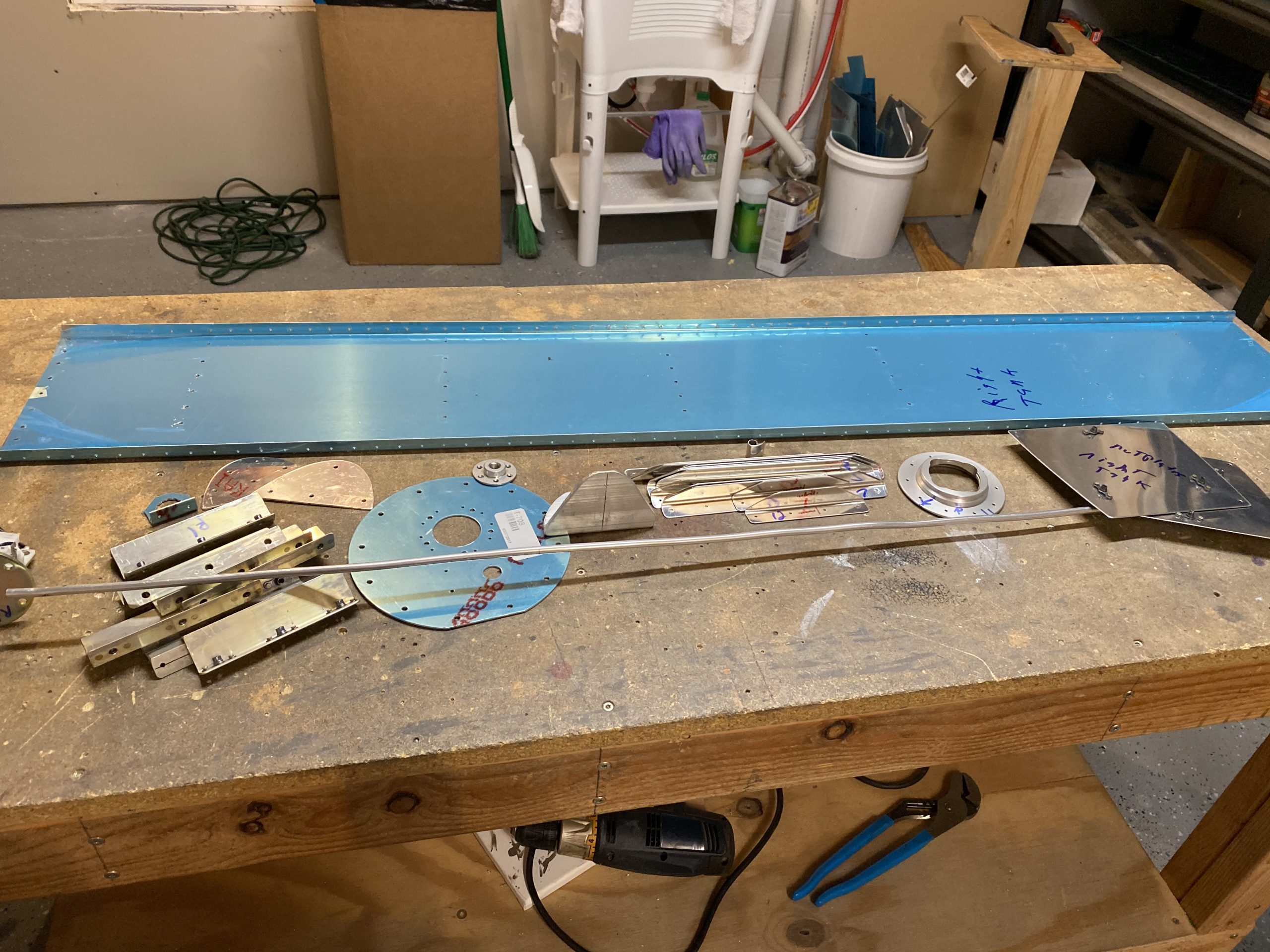
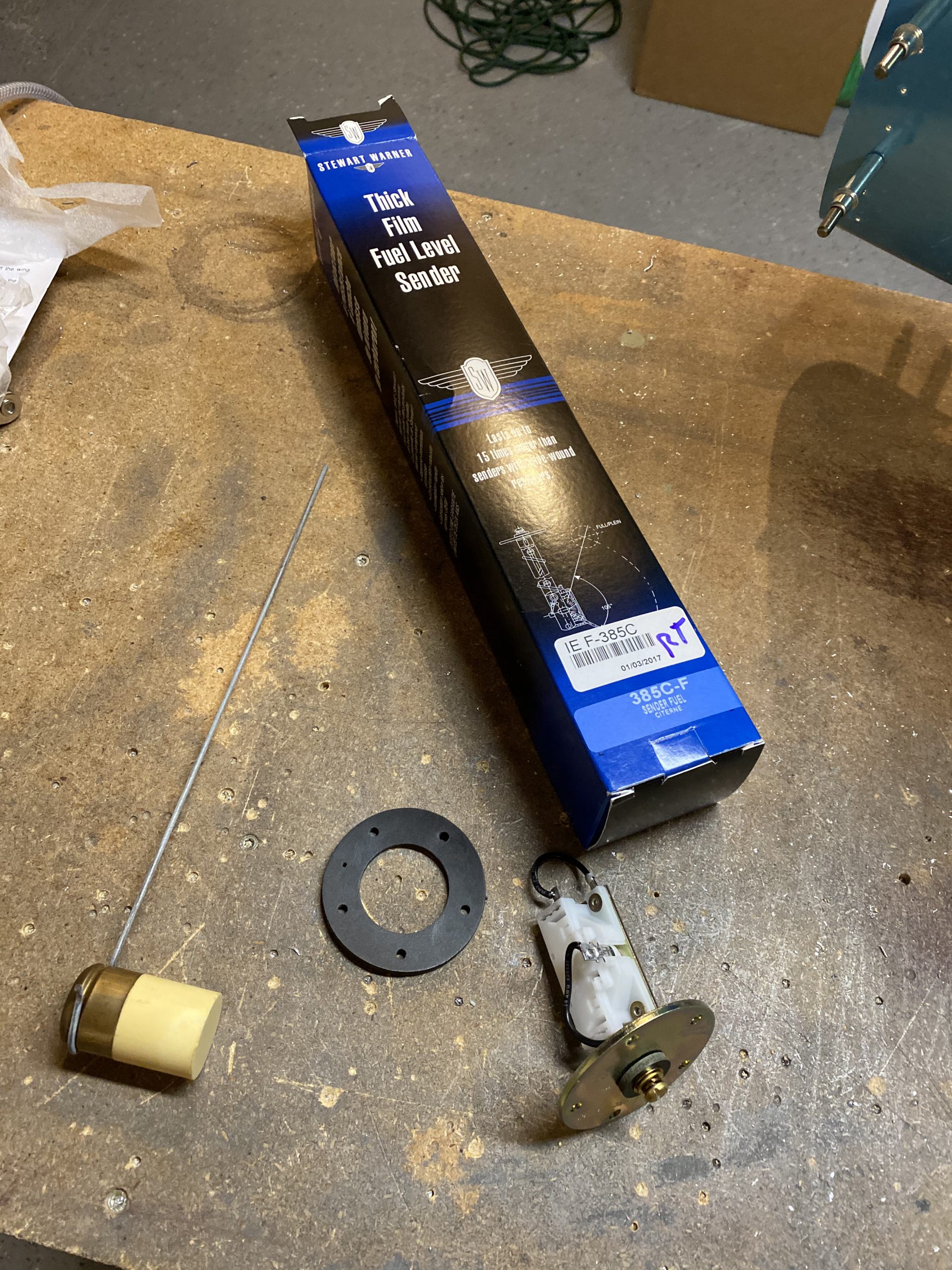
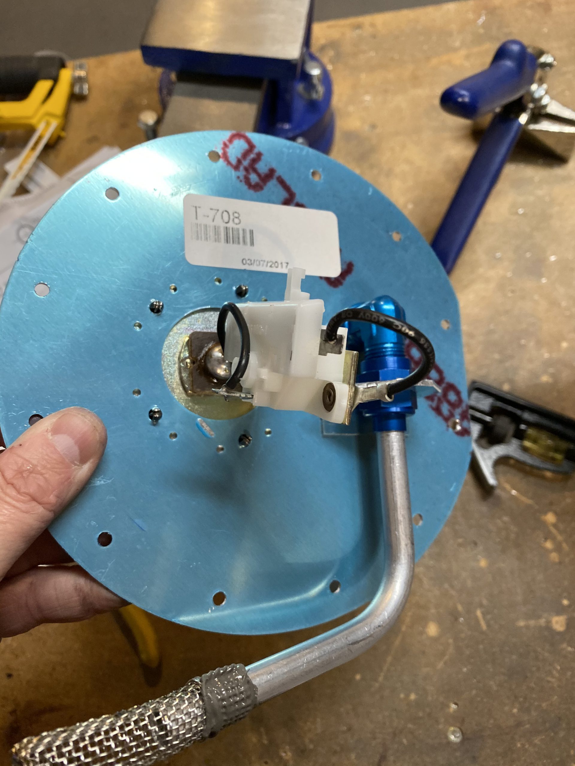
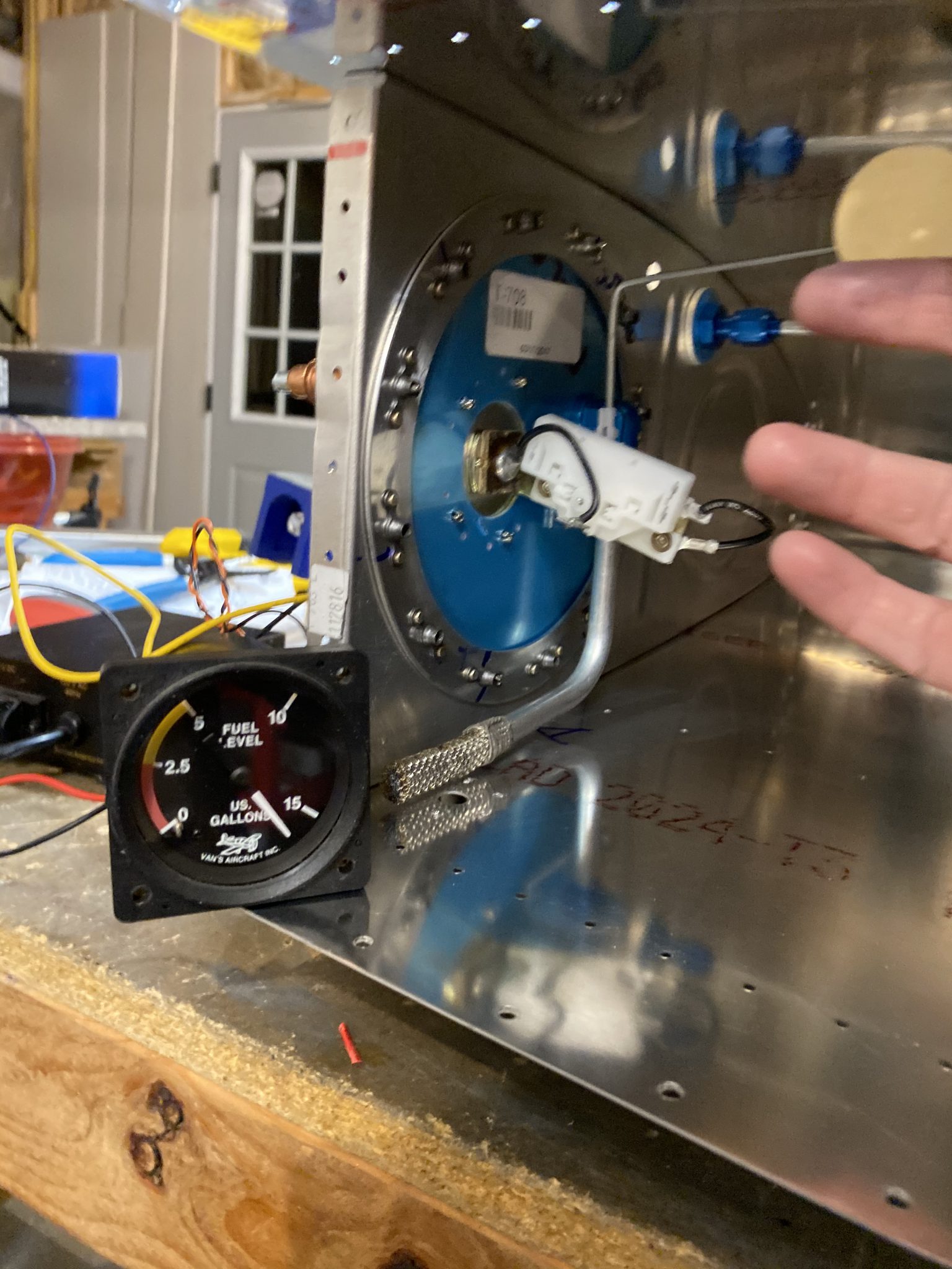
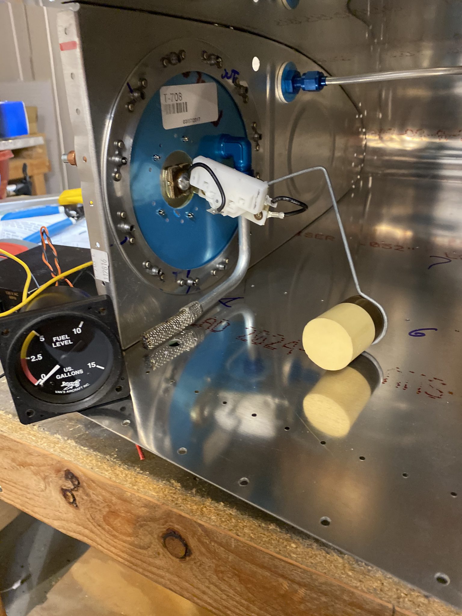
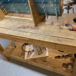
After a quick break and bite to eat, I went back down to do some more work. I decided to go ahead and get the flop tube installed for now, and do the capacitive senders in the next session. I’m only doing a flop tube in one tank: The left tank, so I’ll be sure to placard the fuel selector as “Acro on Left Tank Only” just for the cool factor of it. The real reason is that there is a good bit of extra work to get the flop tube installed, and you have to move the float fuel level senders out from the access panel to one of the inner fuel bays, making it damn near impossible to service it if needed. Thats one reason I am also installing capacitive fuel sender plates in my tanks, they’ll give me a backup fuel level source, and they are pretty easy to install during assembly and they need zero maintenance. So, I’ll install both capacitive and float senders in my tanks. The right tank will have the standard Vans fuel pickup, and it’ll be standard assembly as well.
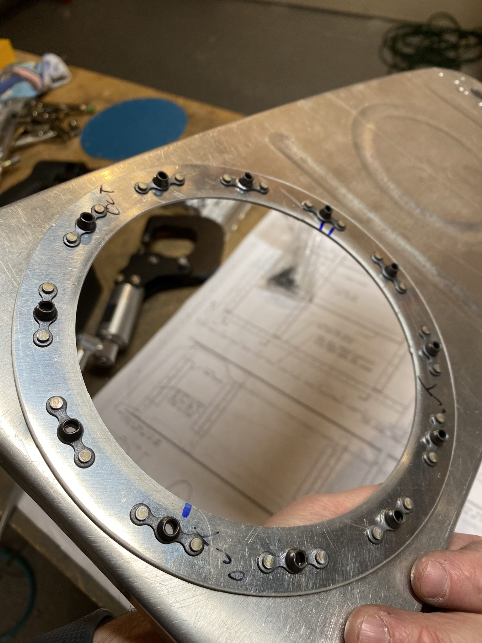
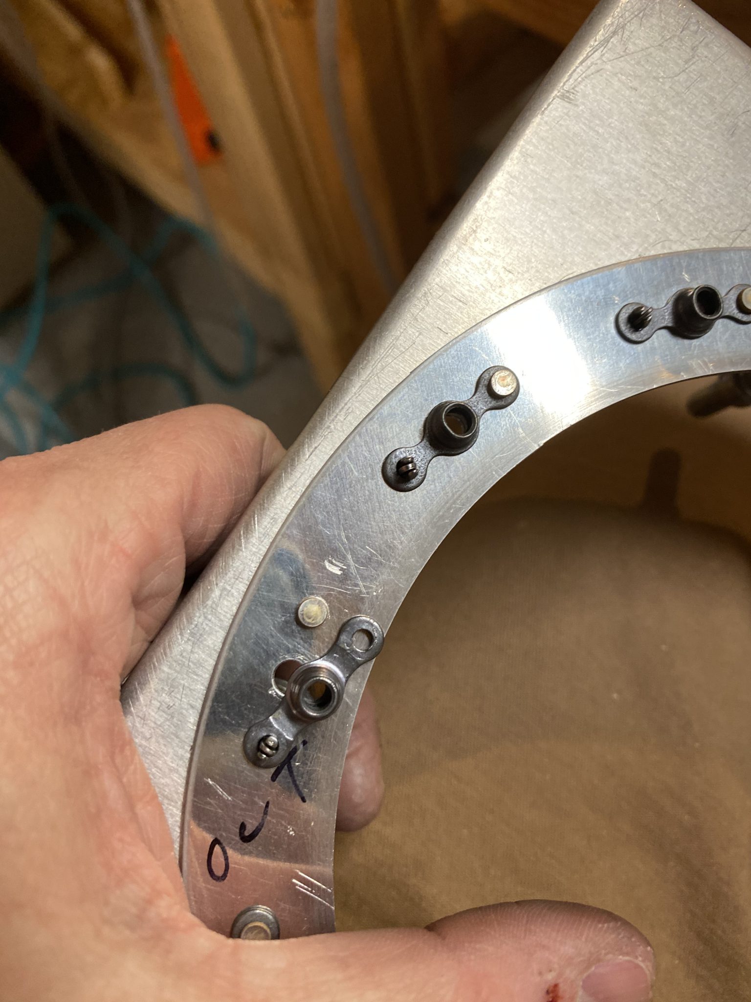
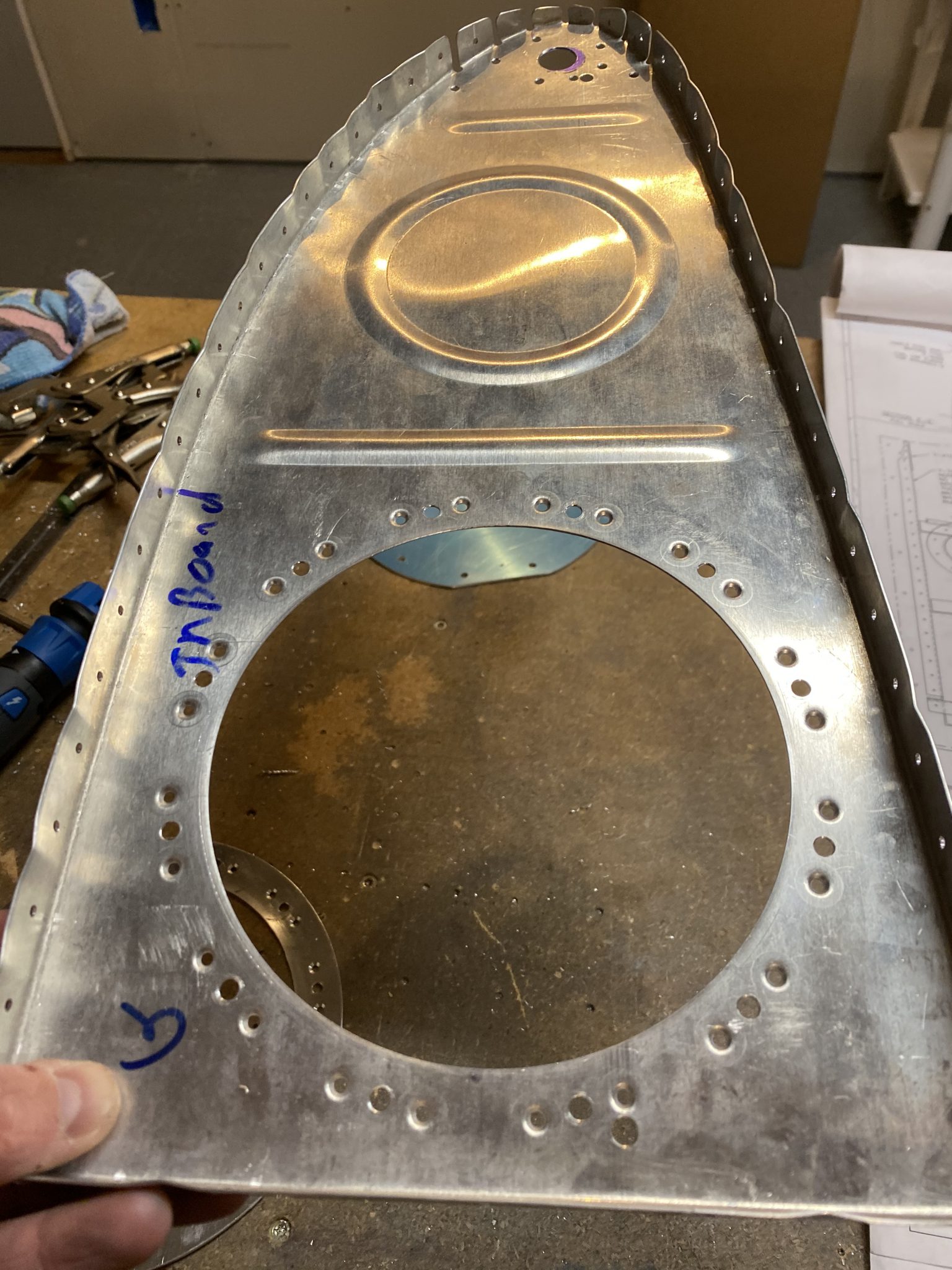
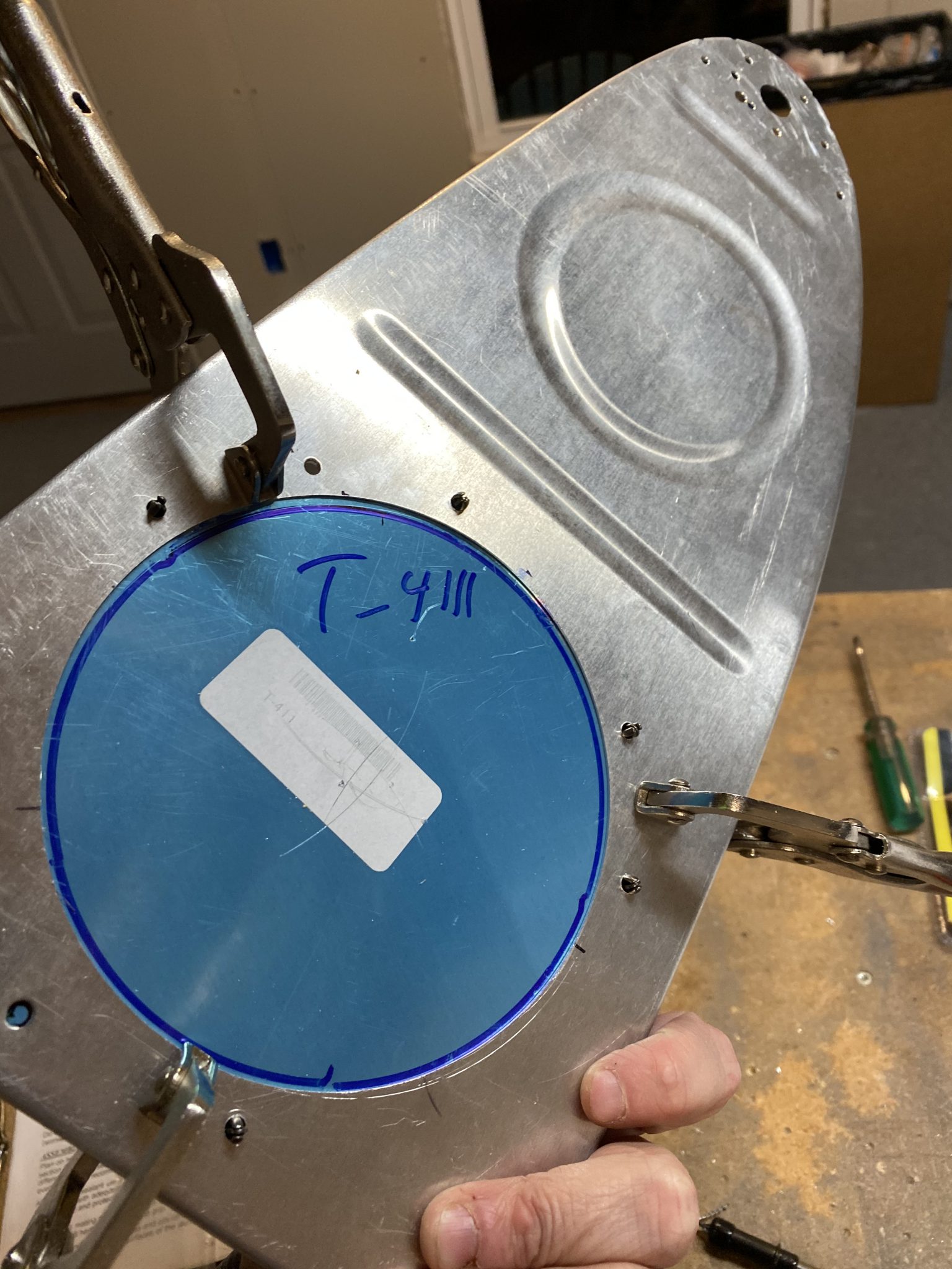
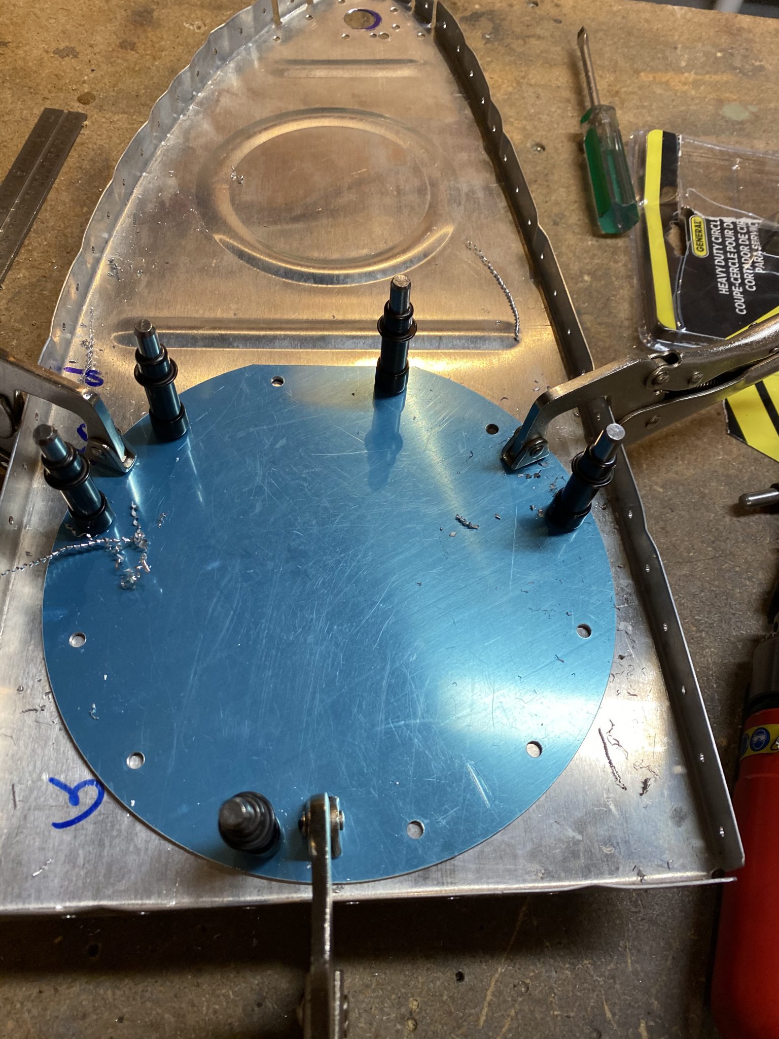
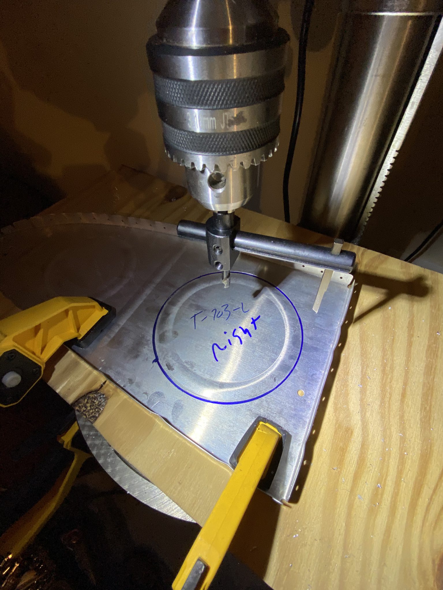
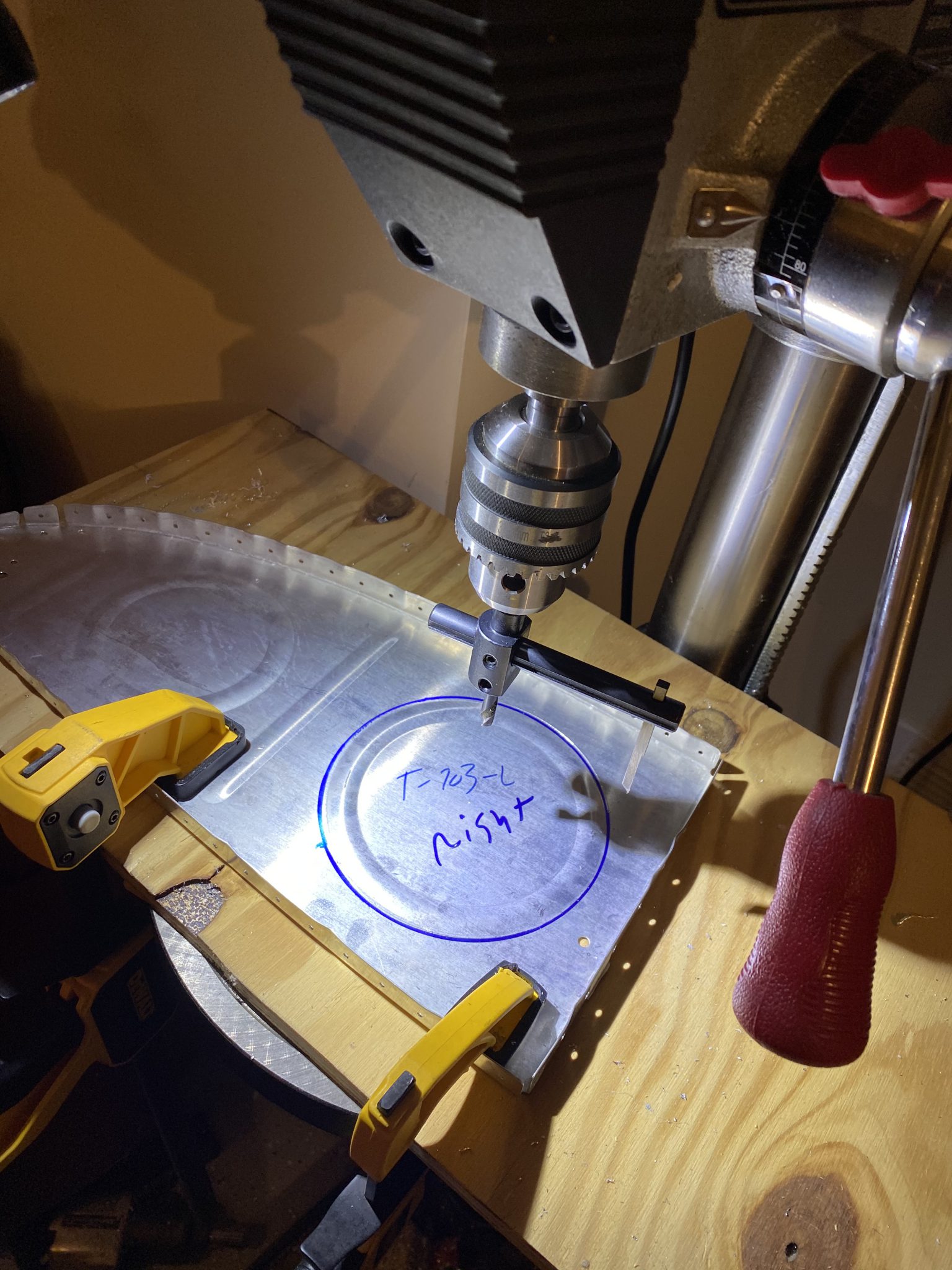
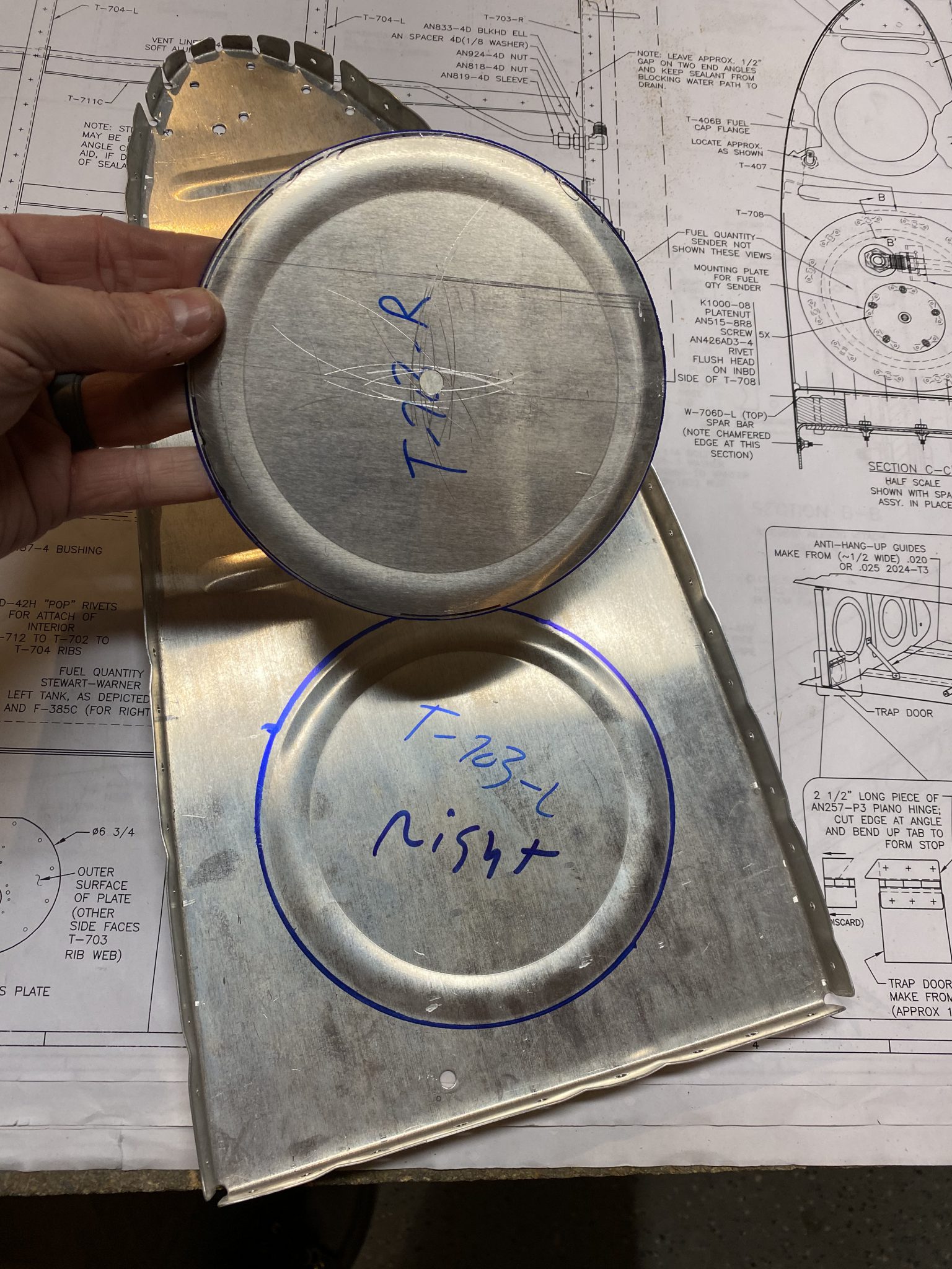
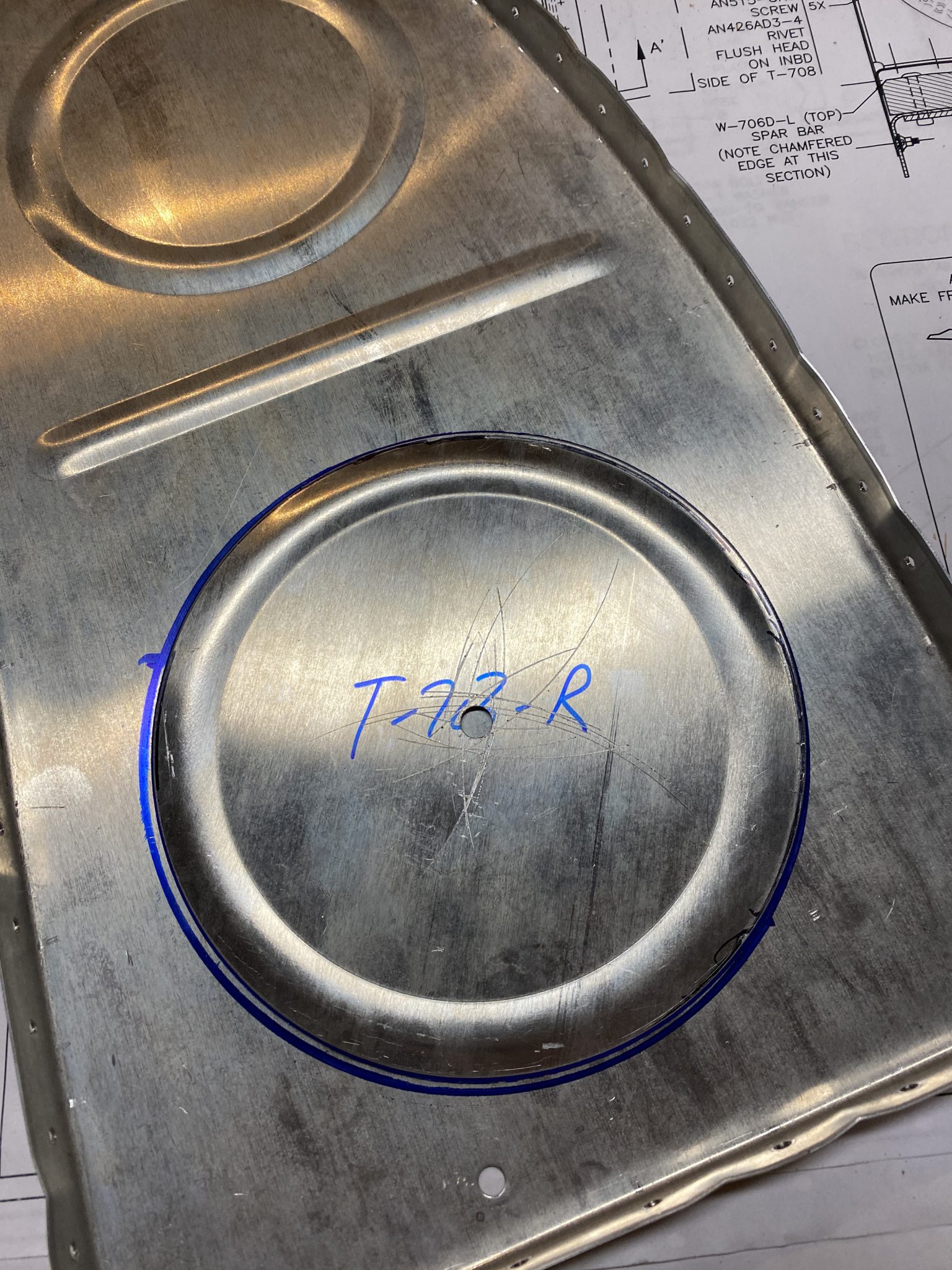
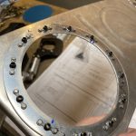
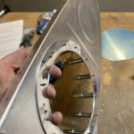
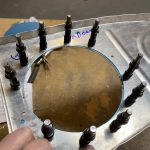
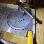
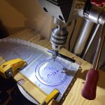
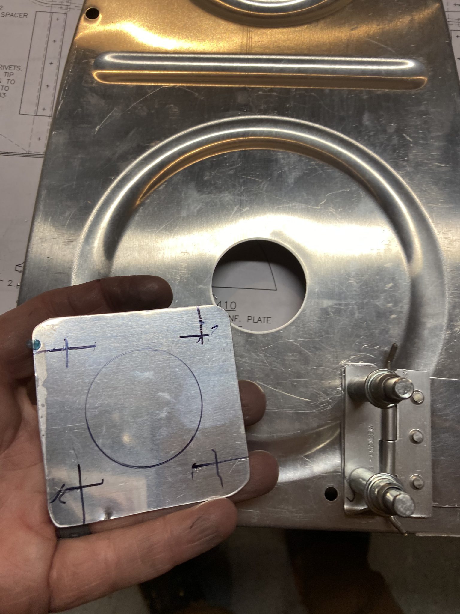
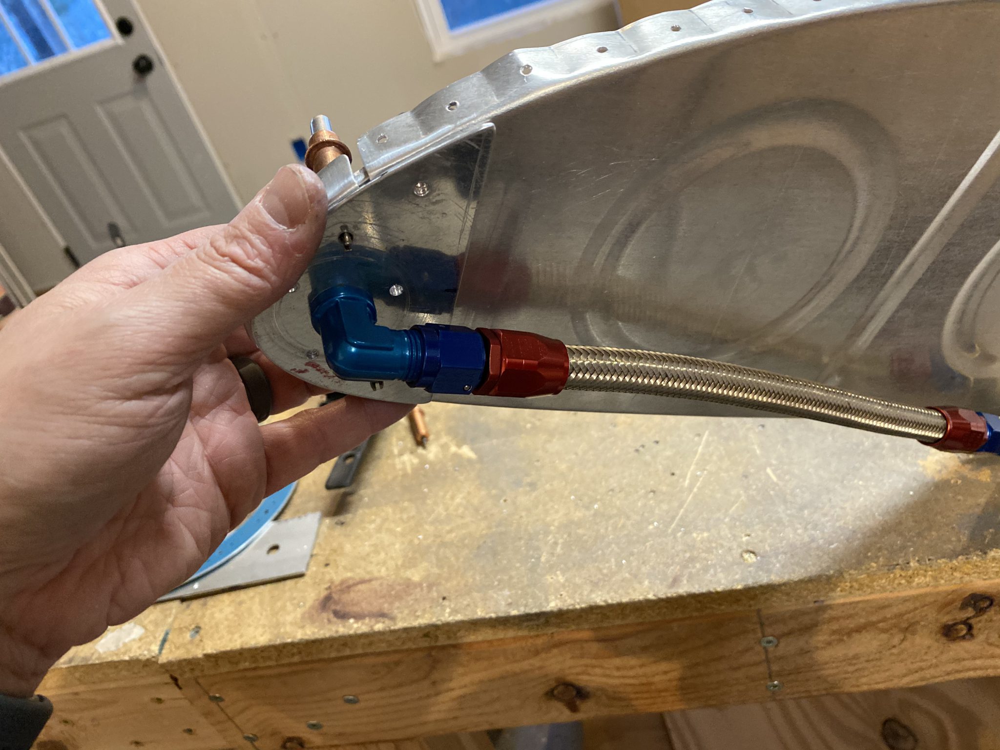
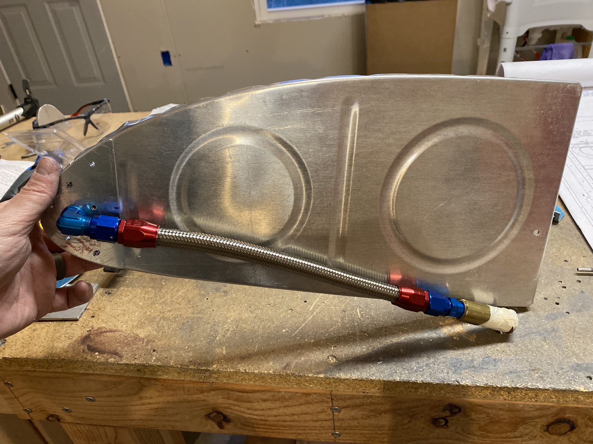
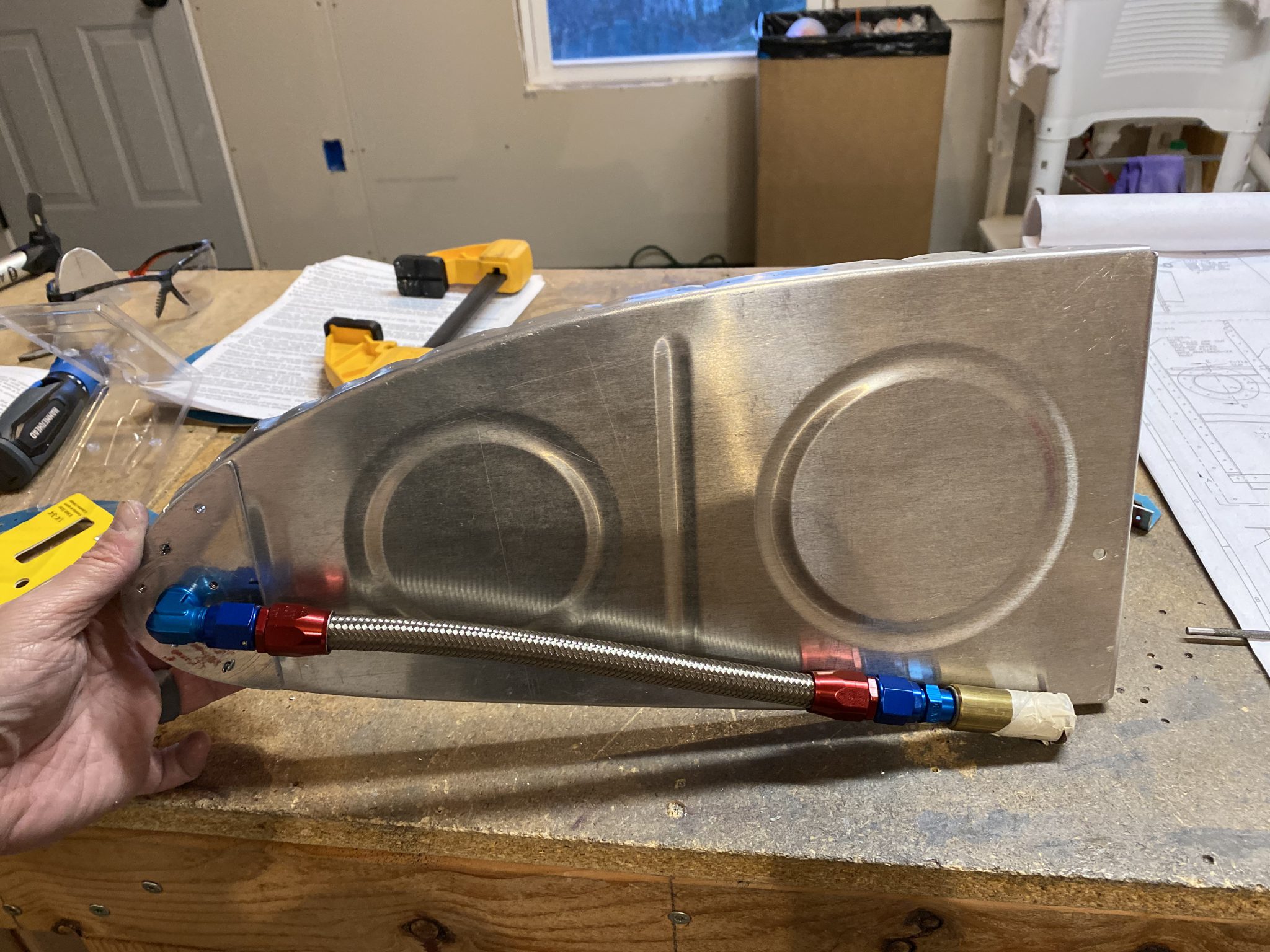
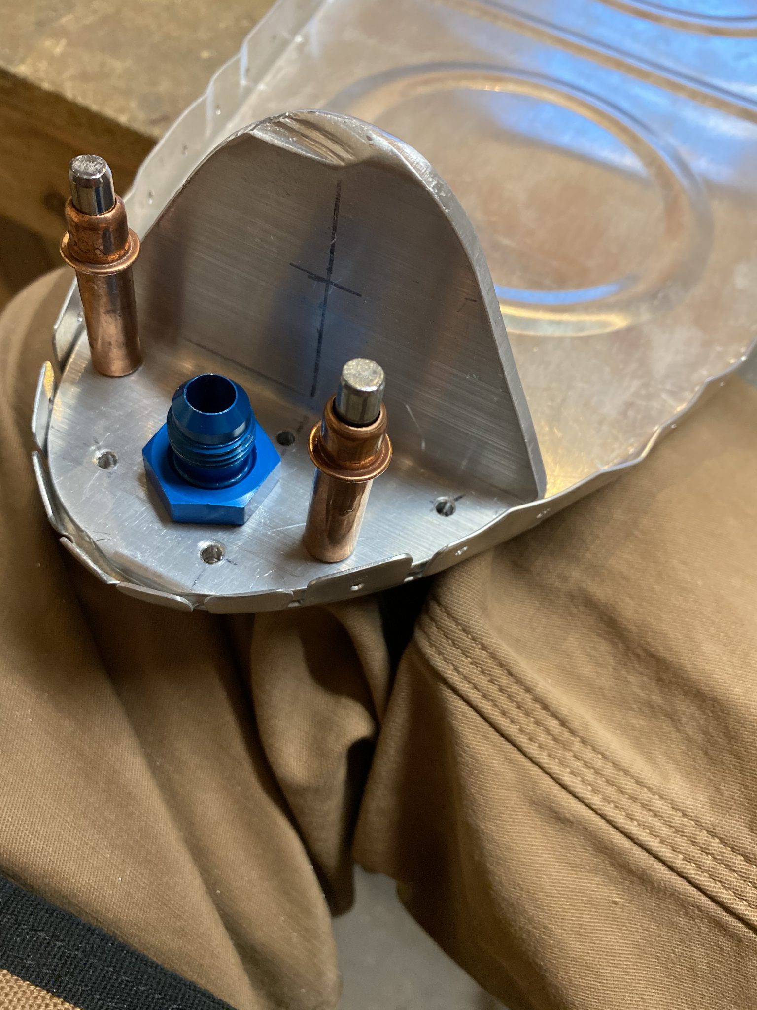
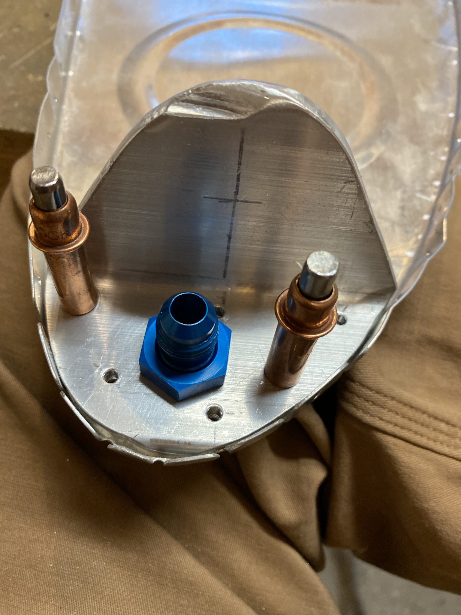
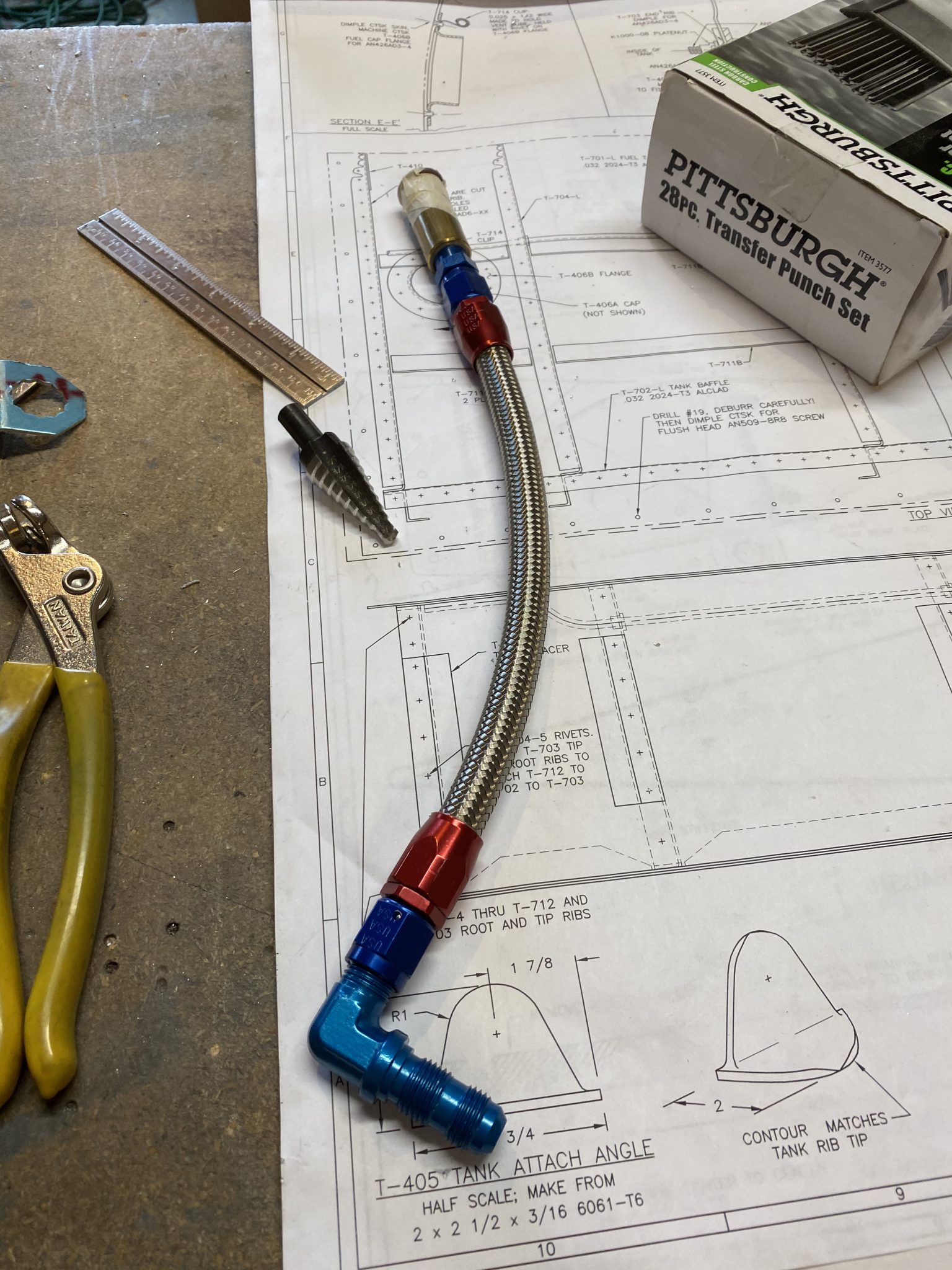
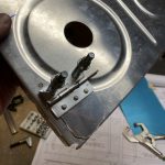
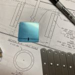
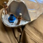
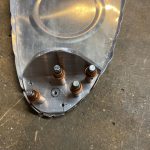
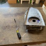
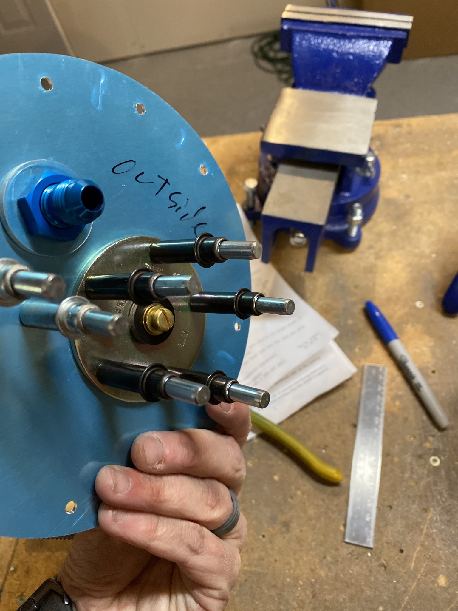
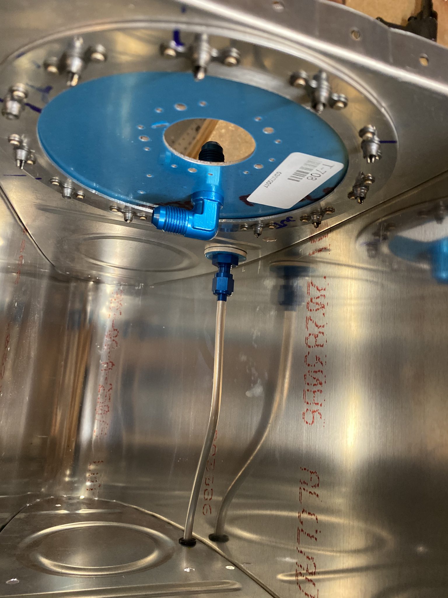
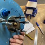
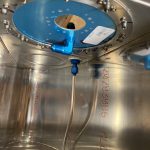
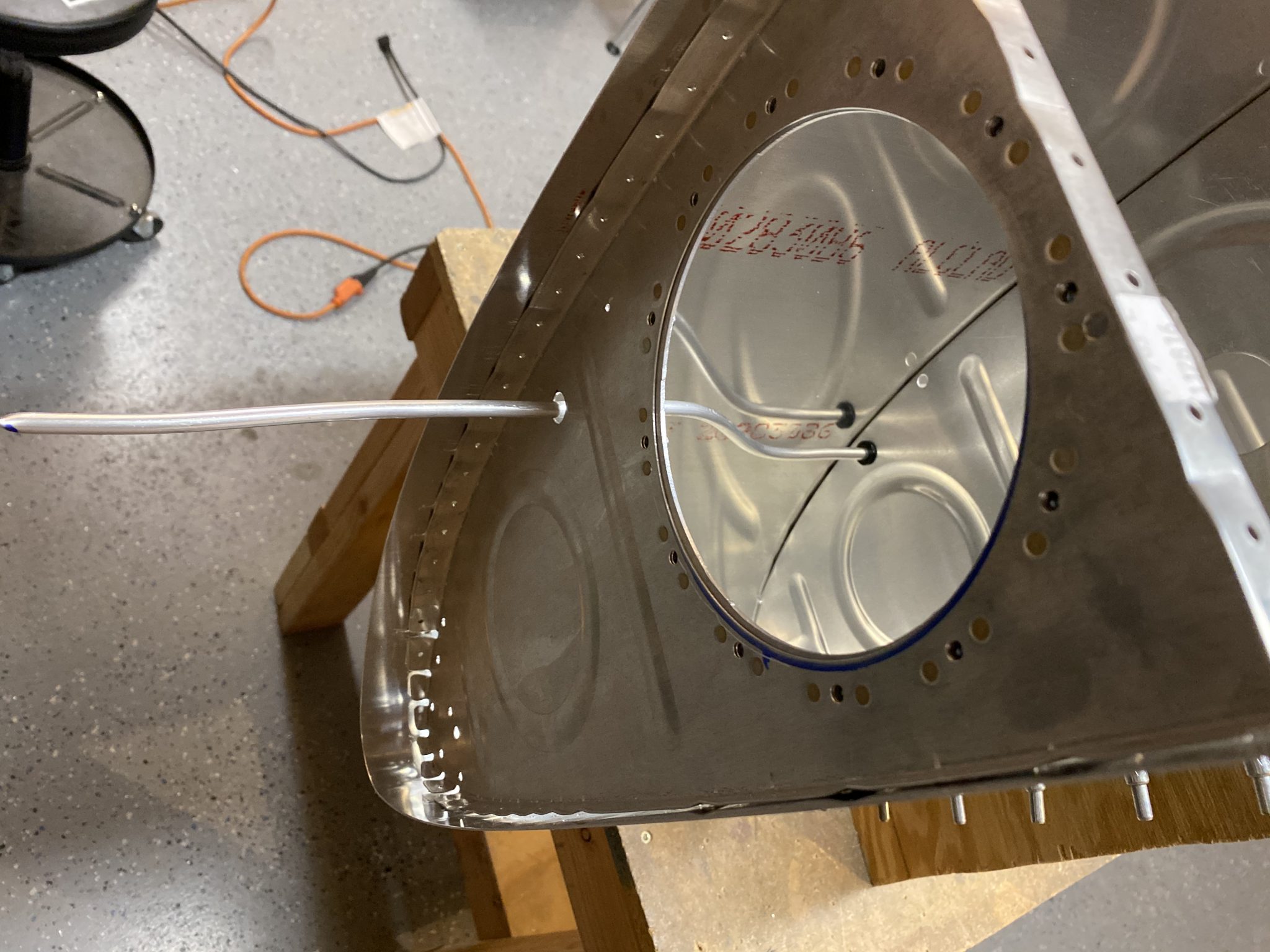
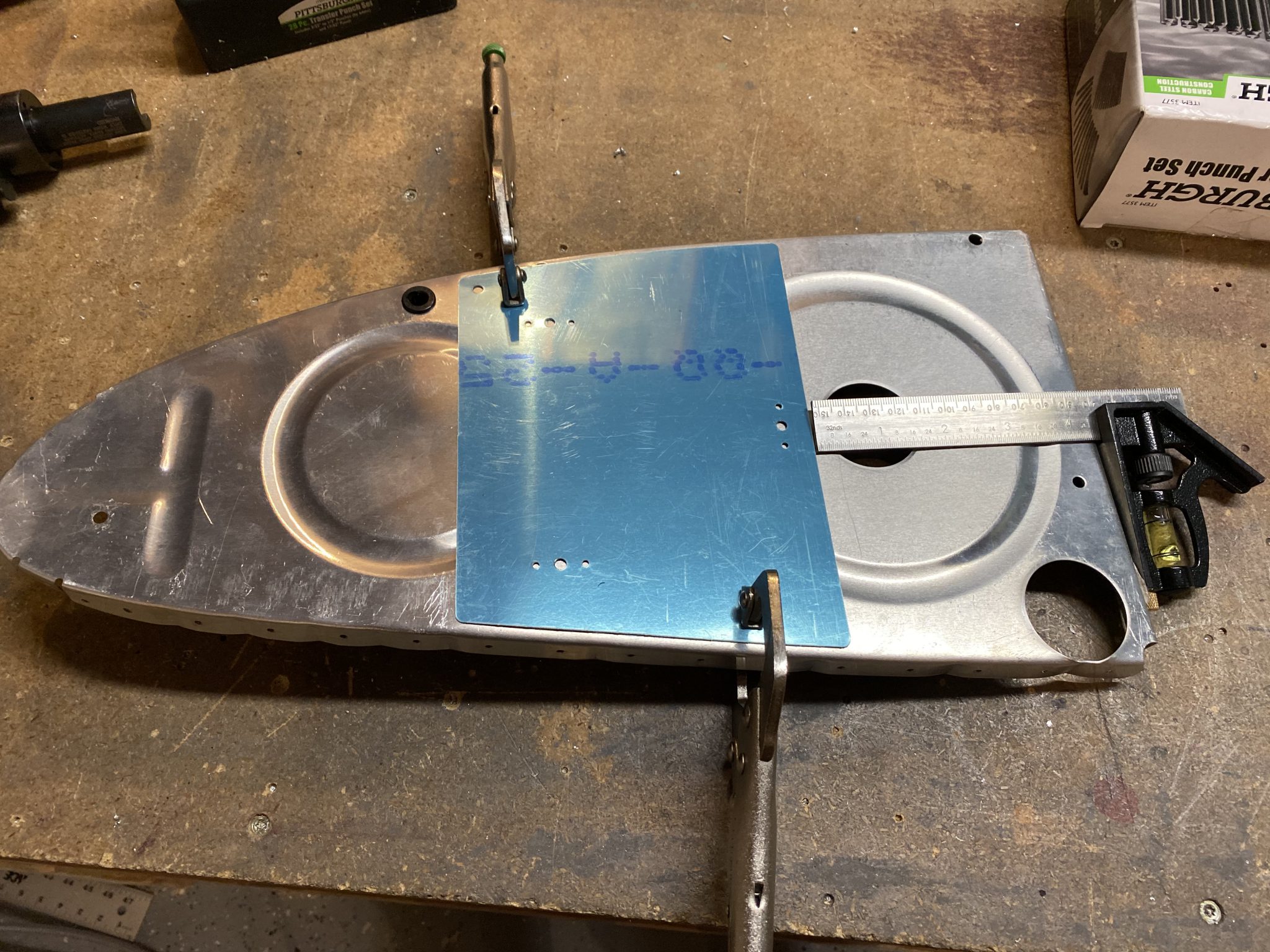
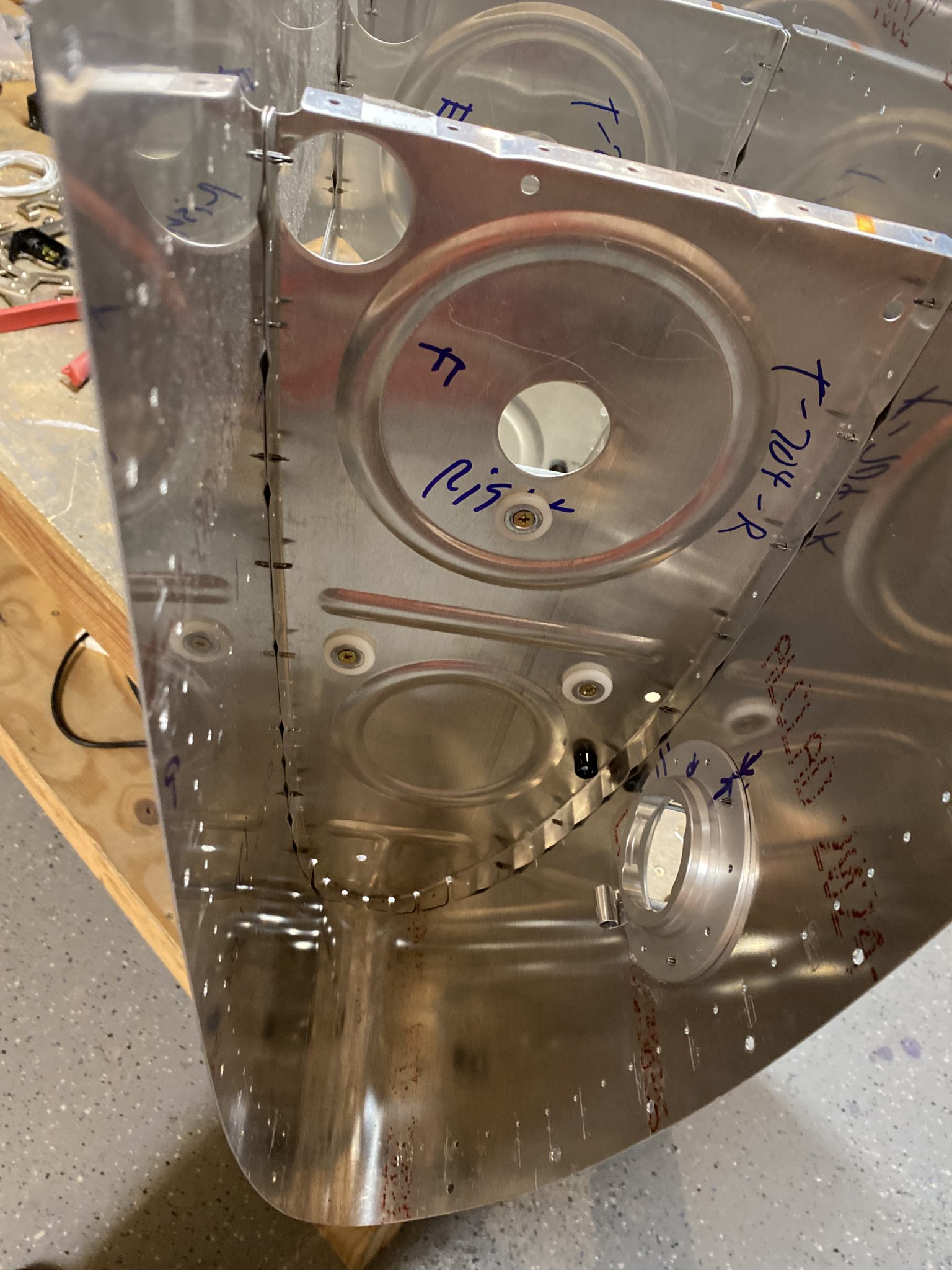
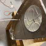
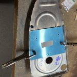
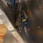
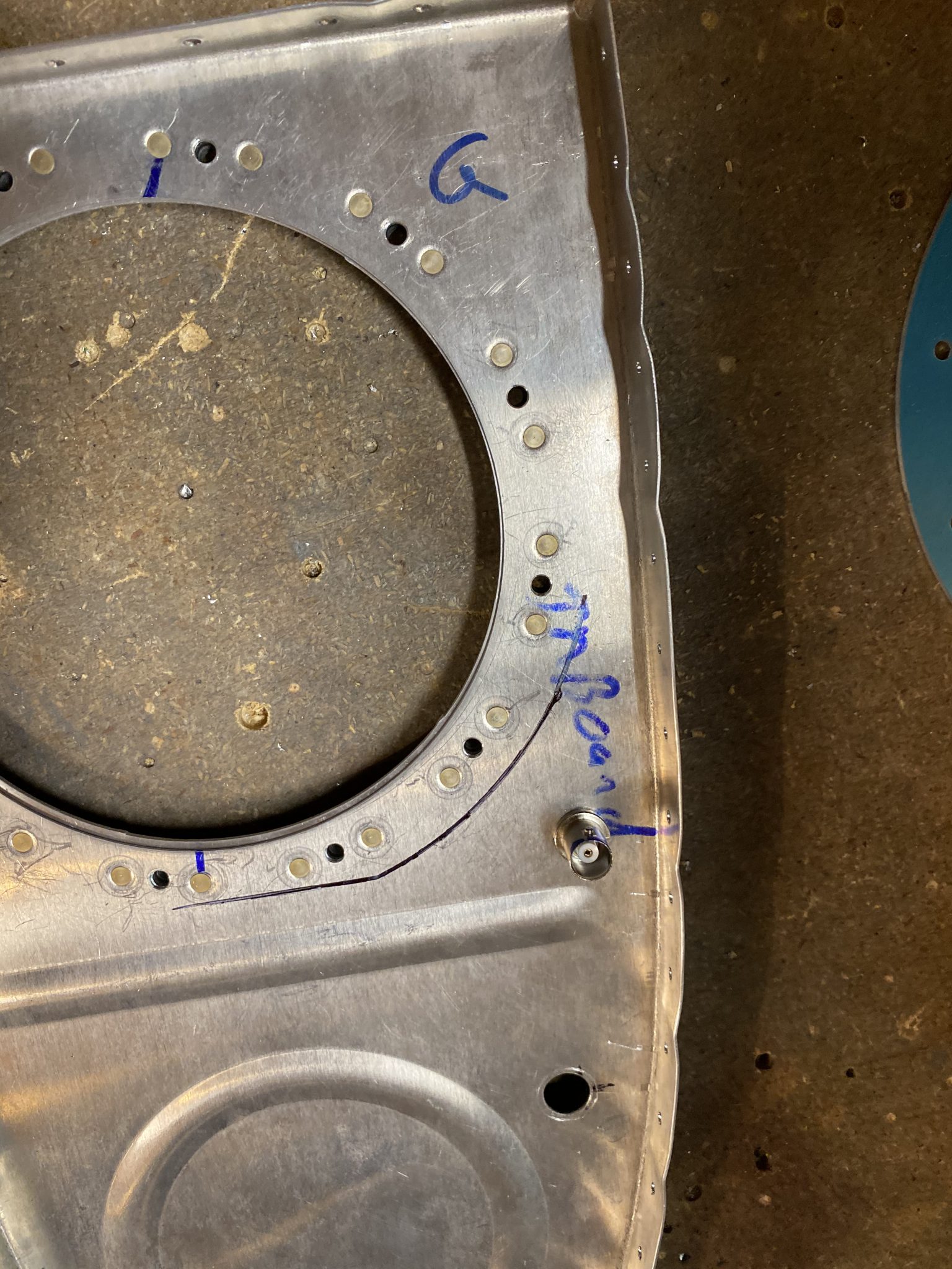
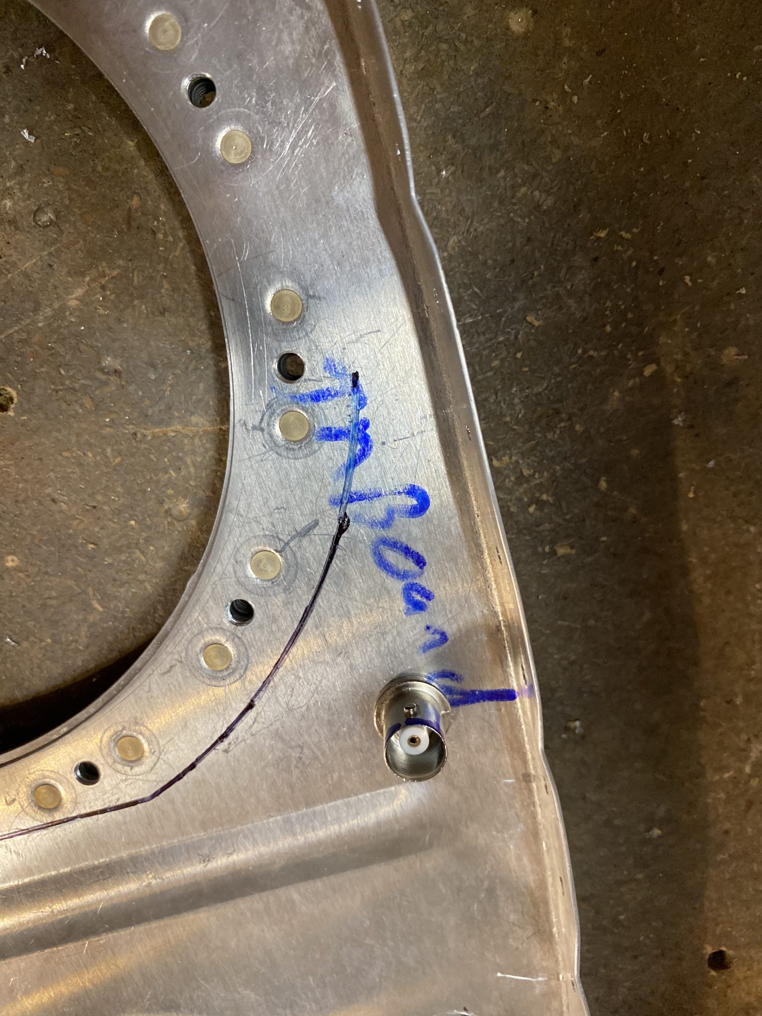
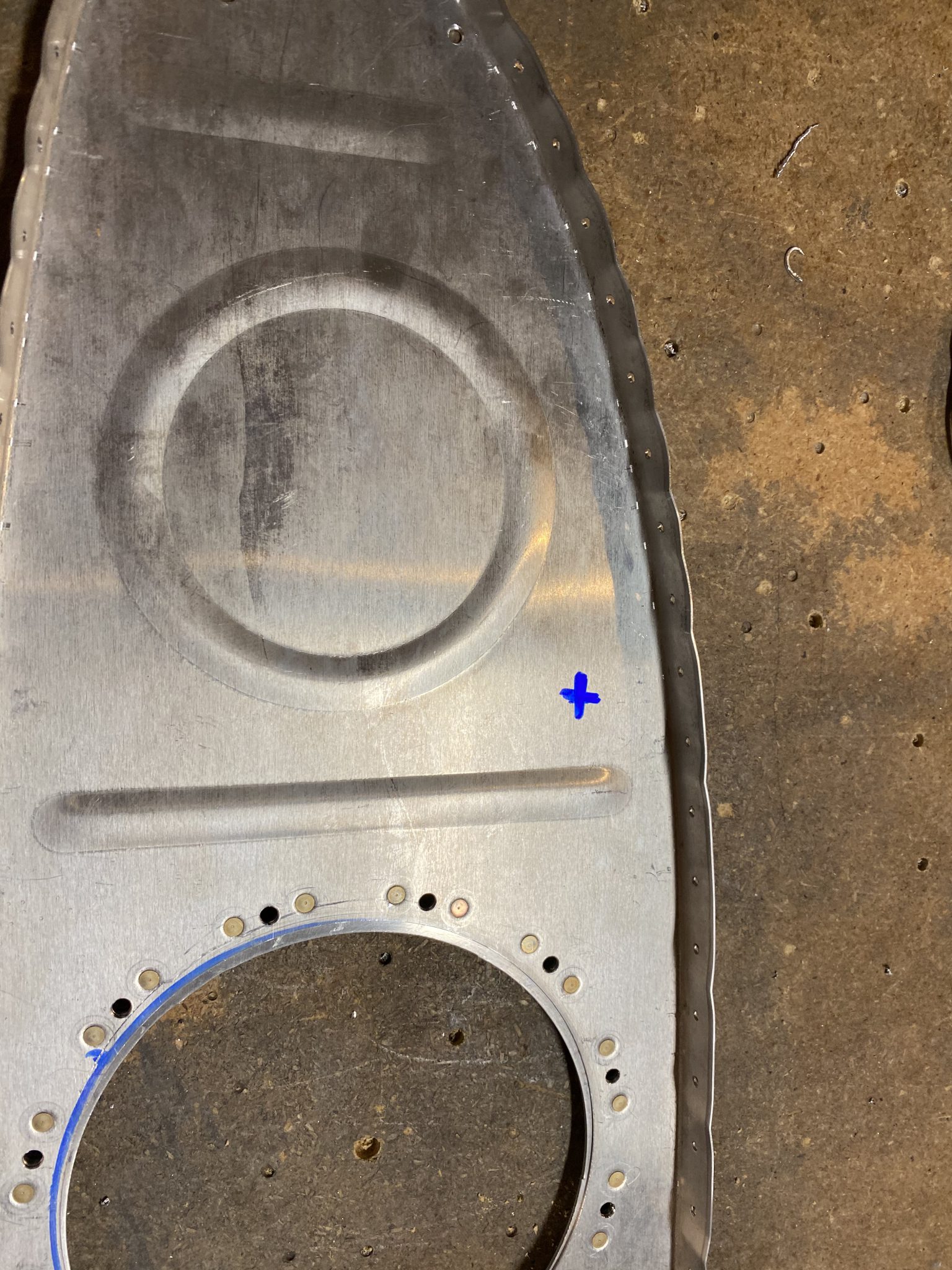
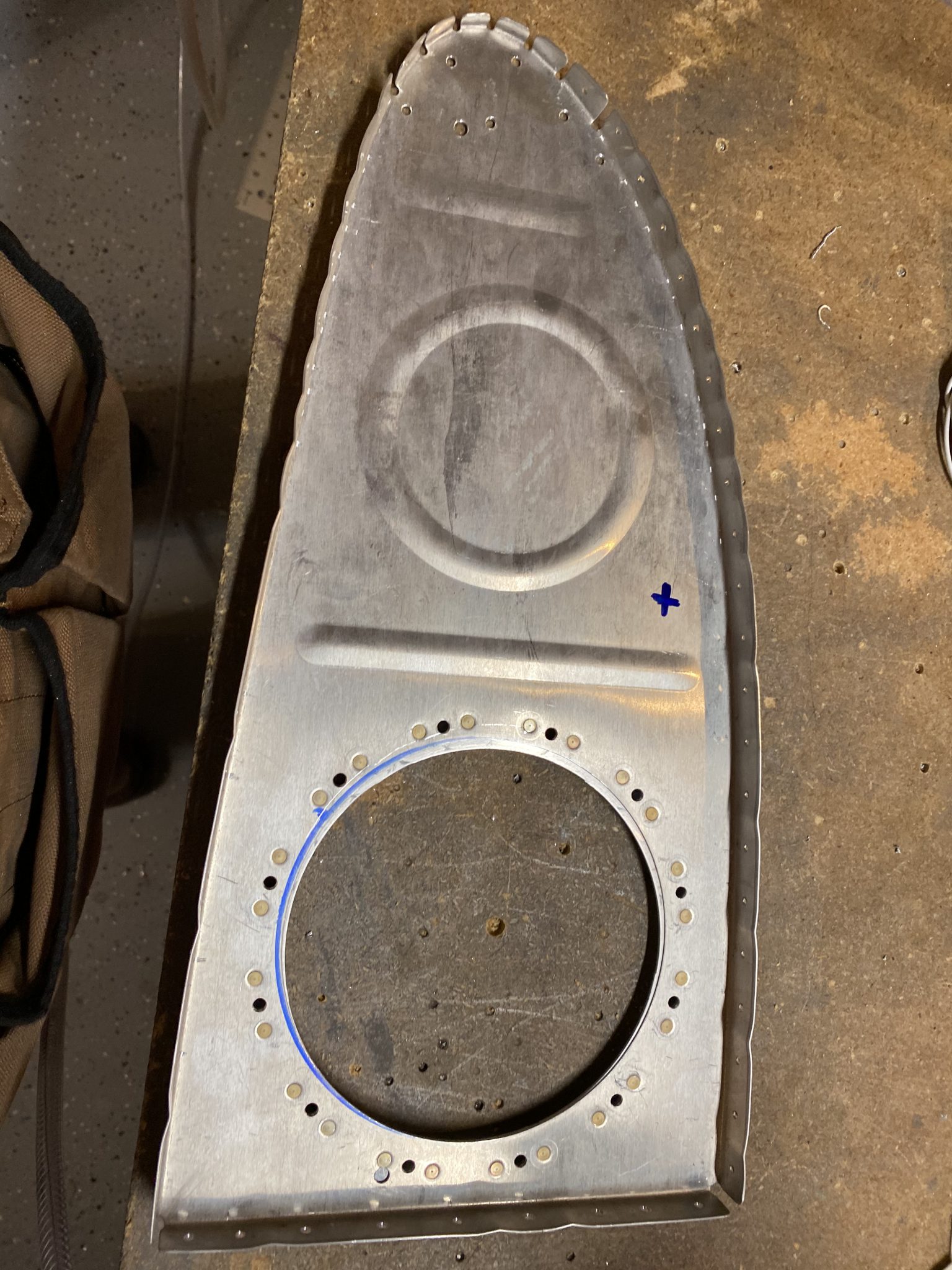
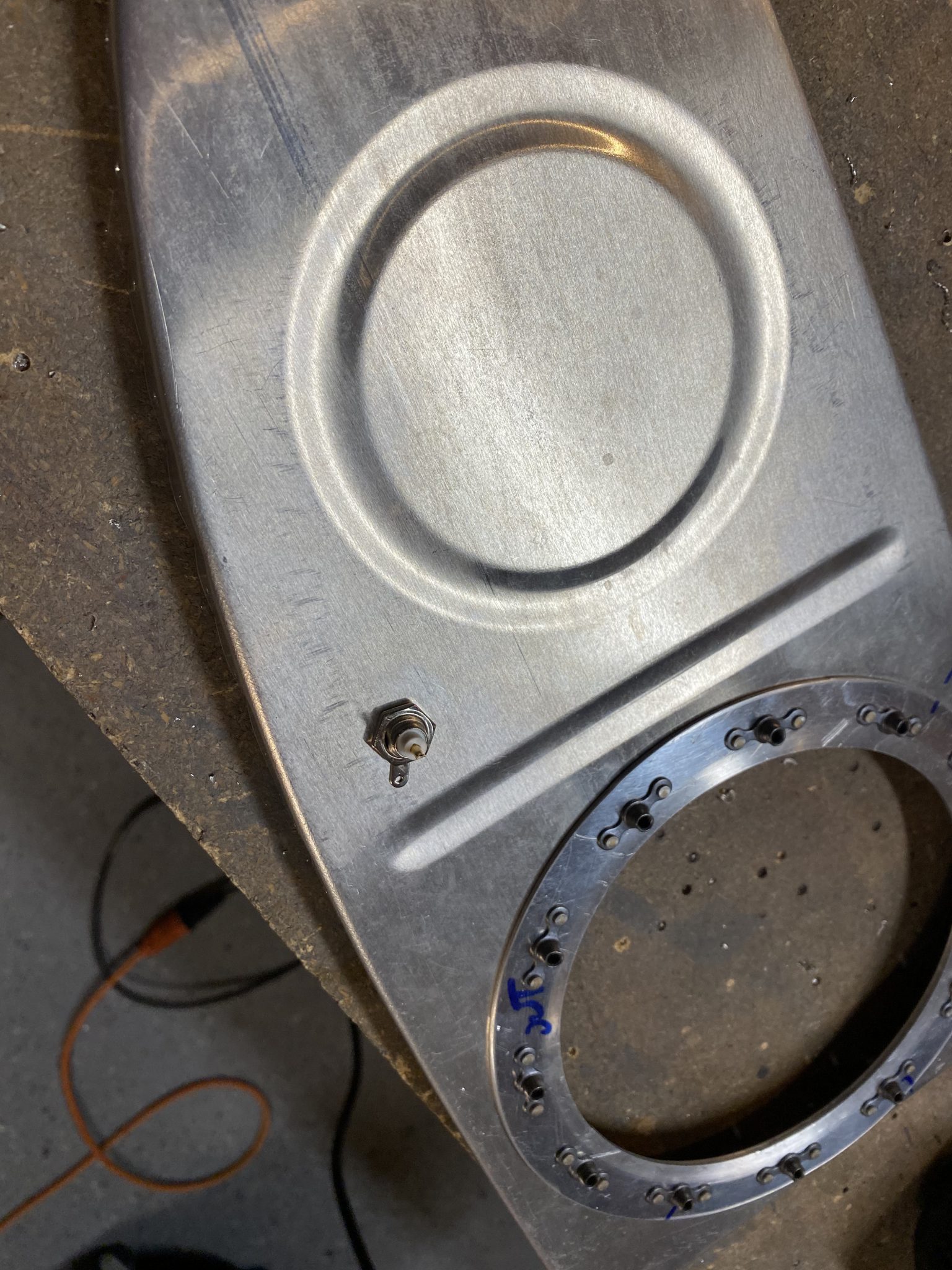
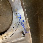
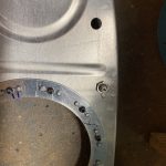
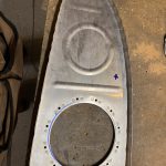
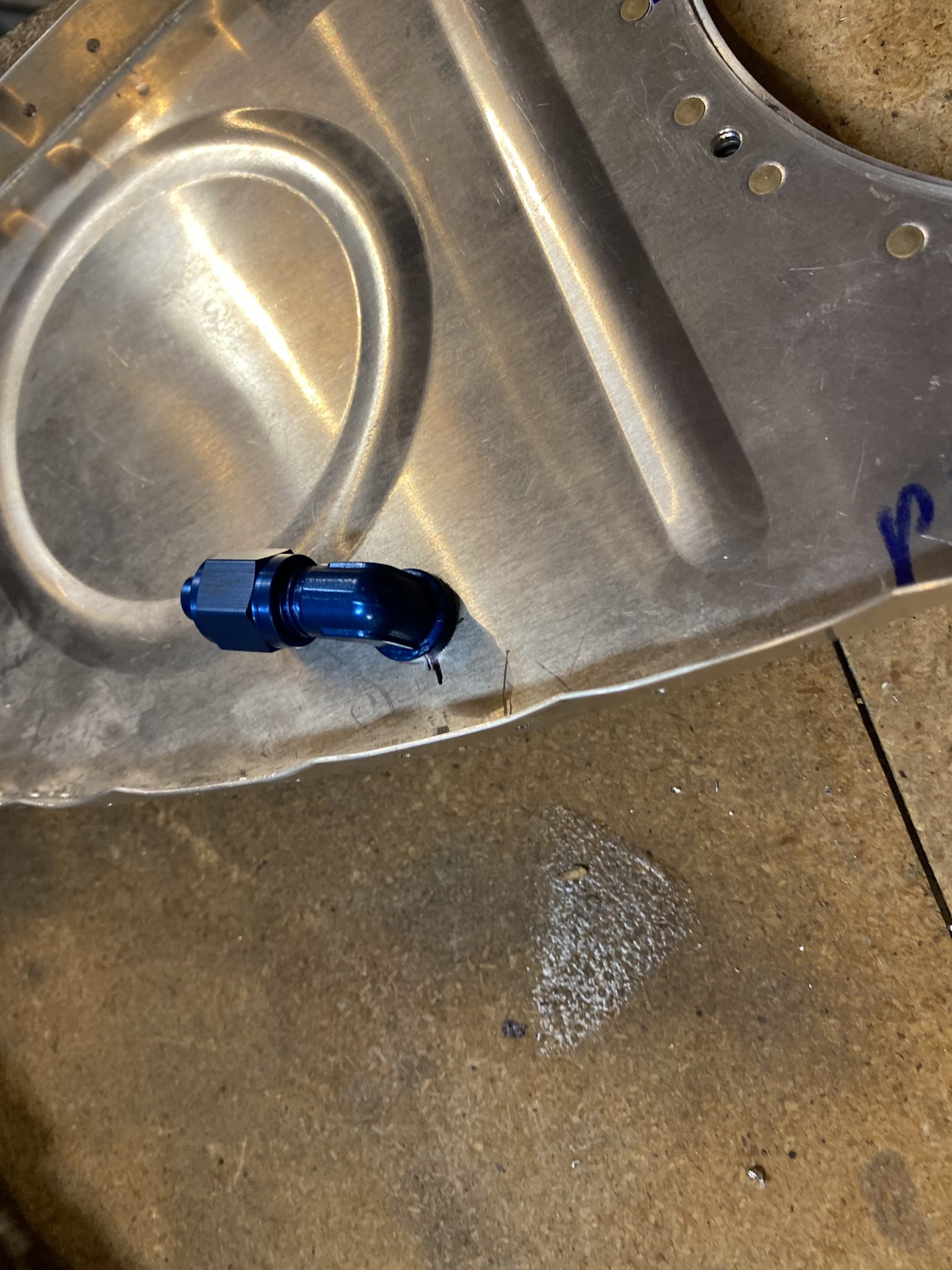
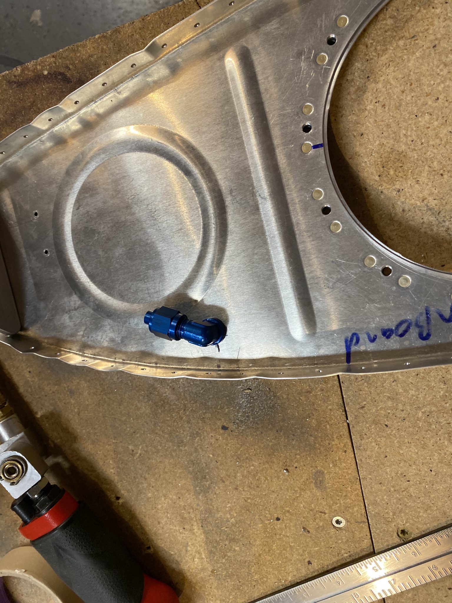
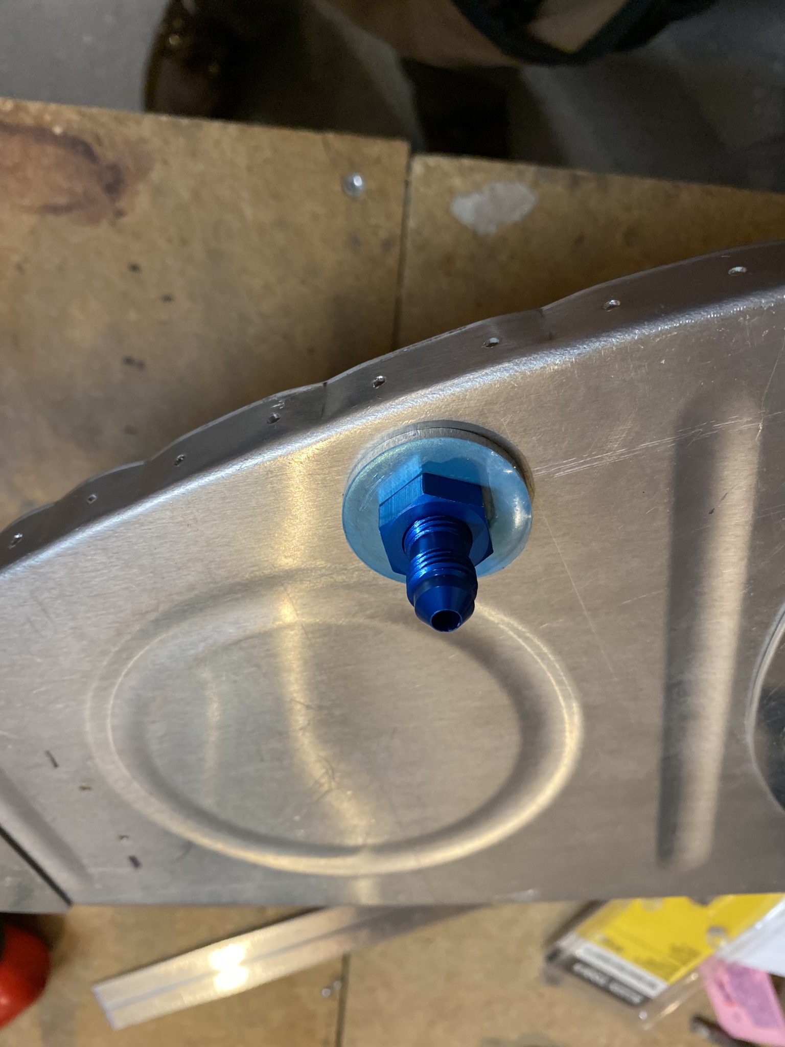
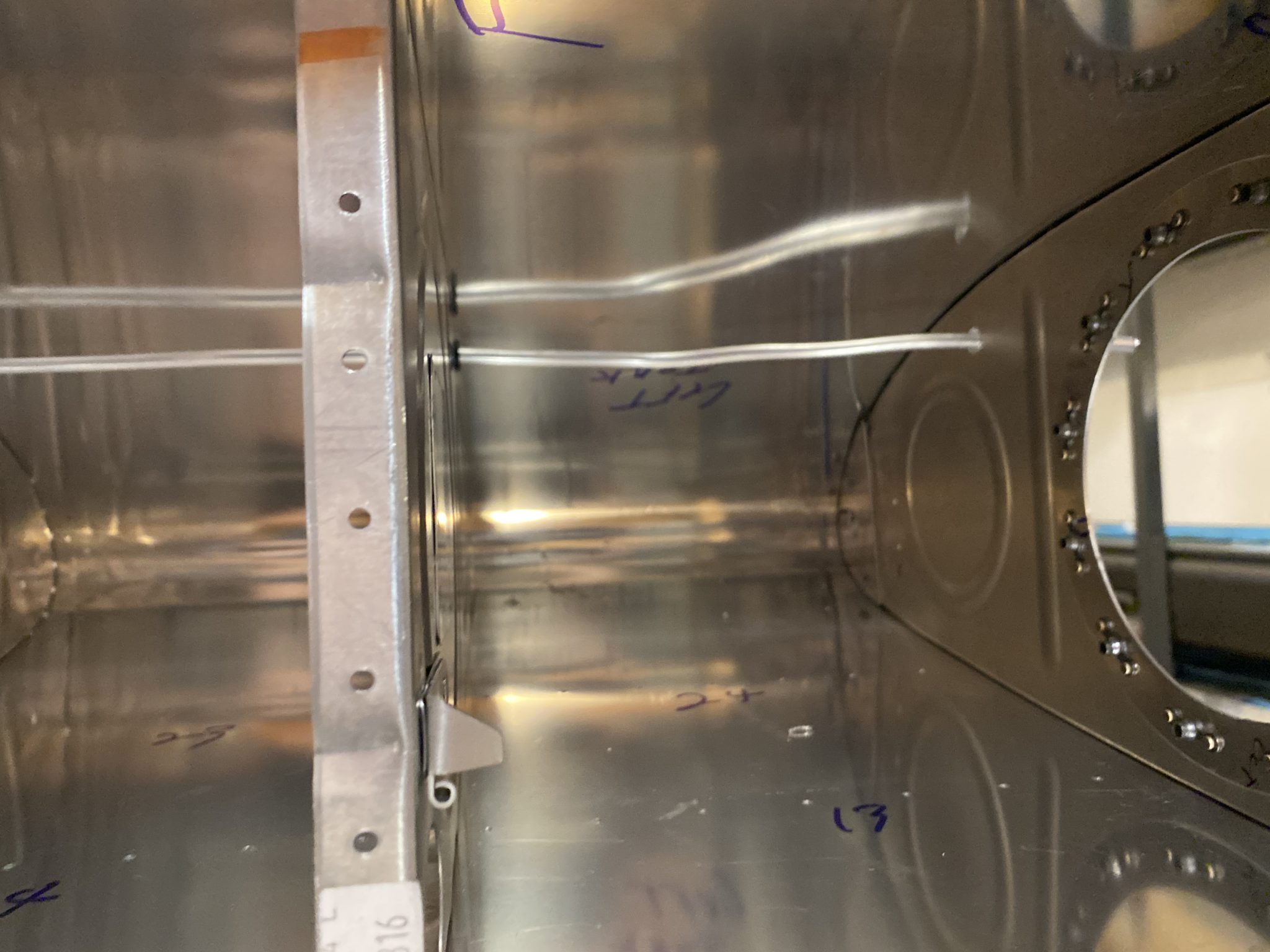
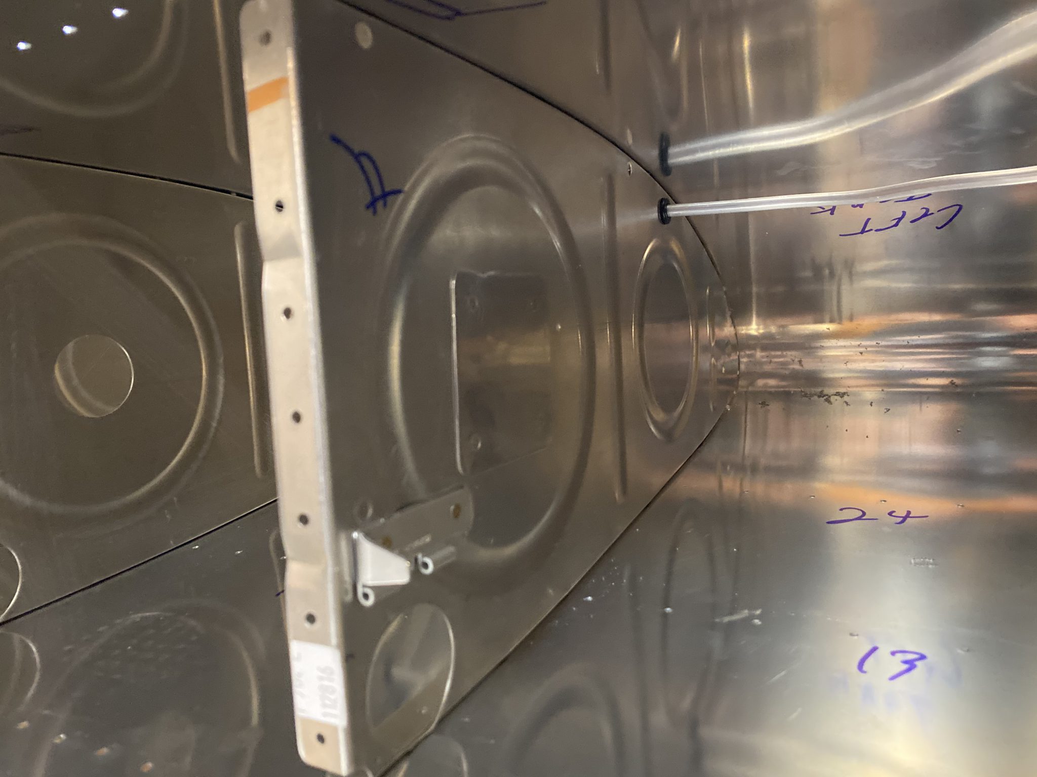
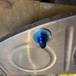
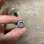
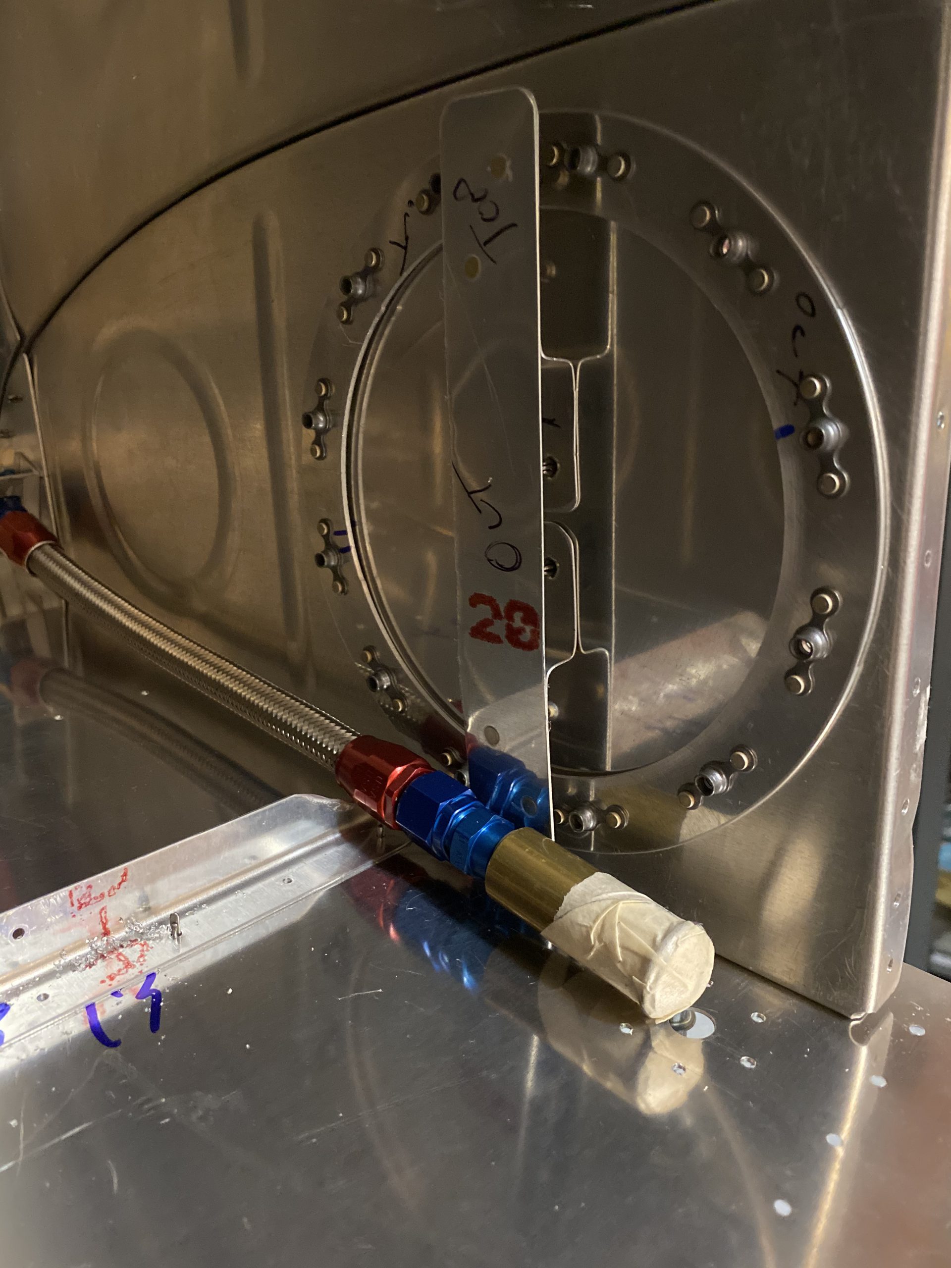
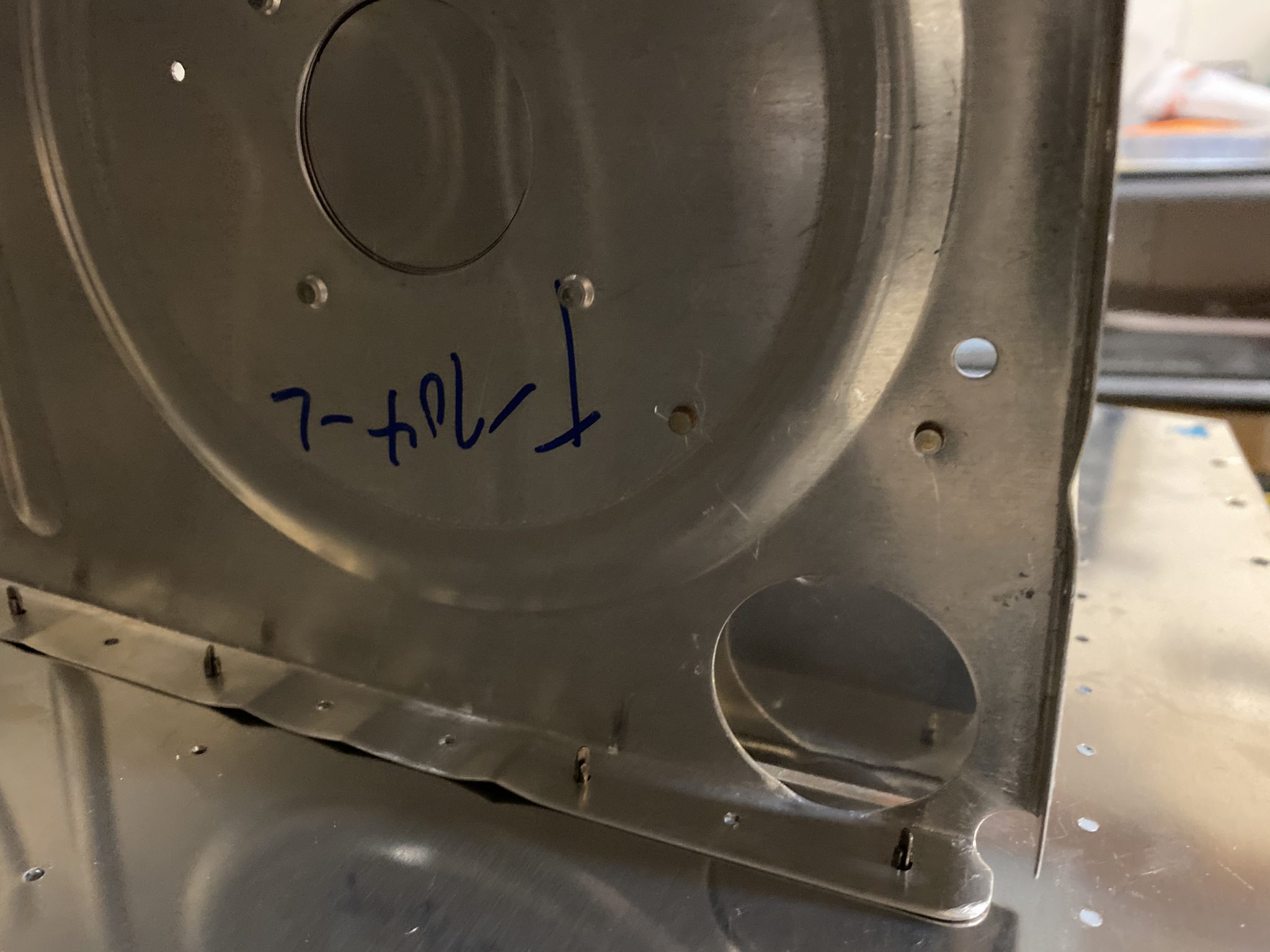
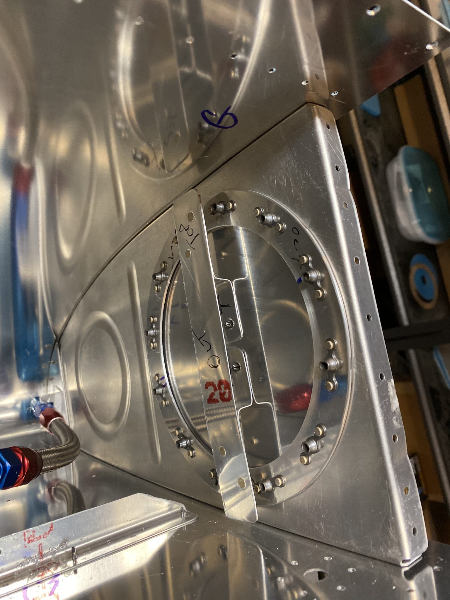
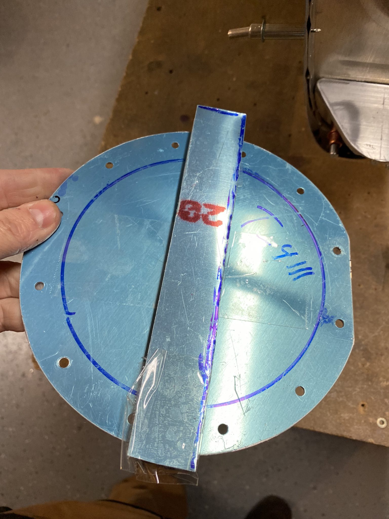
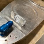
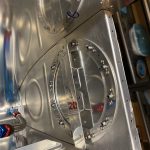
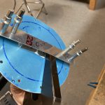
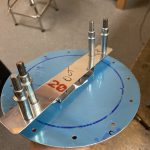
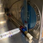
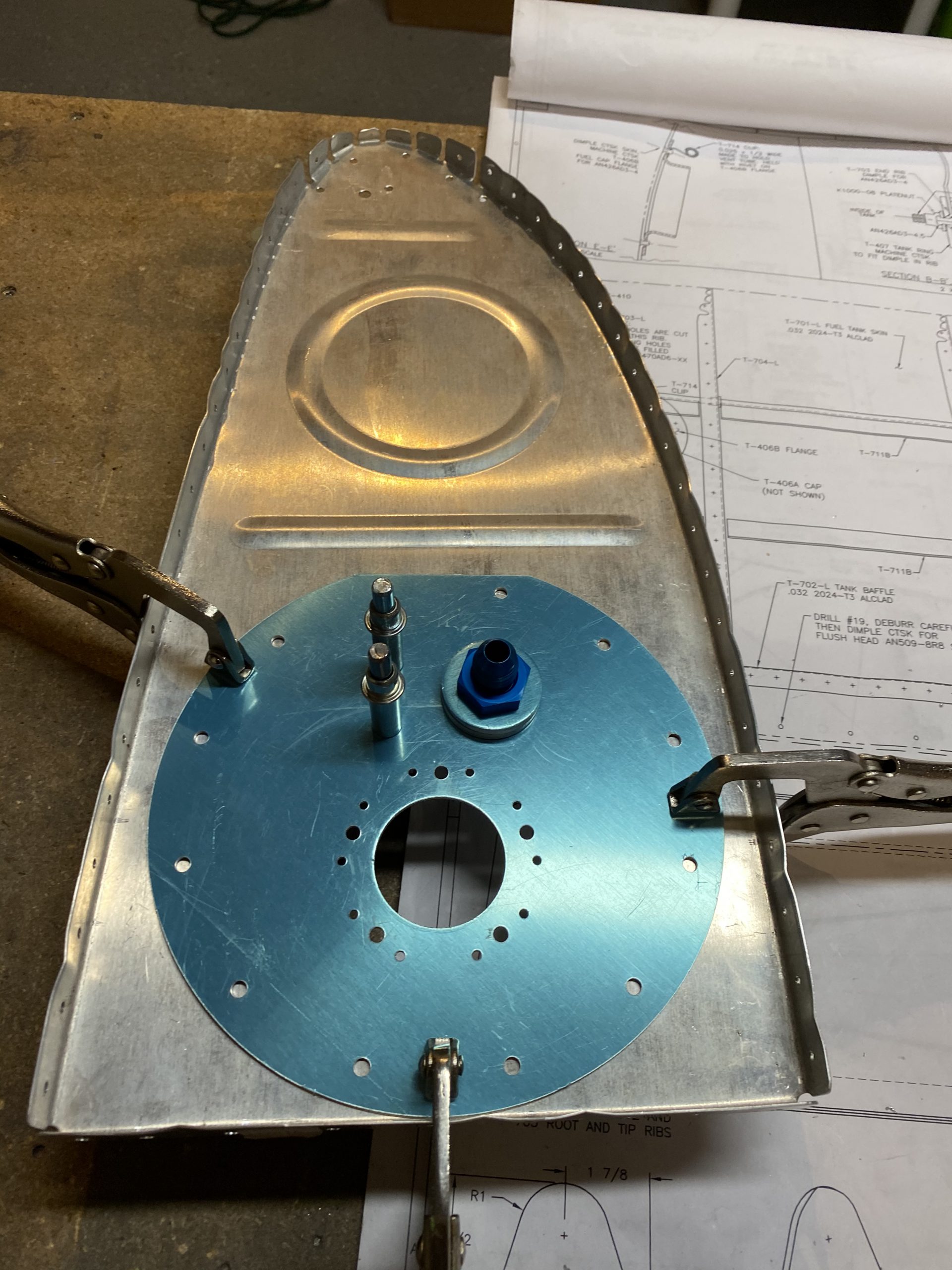
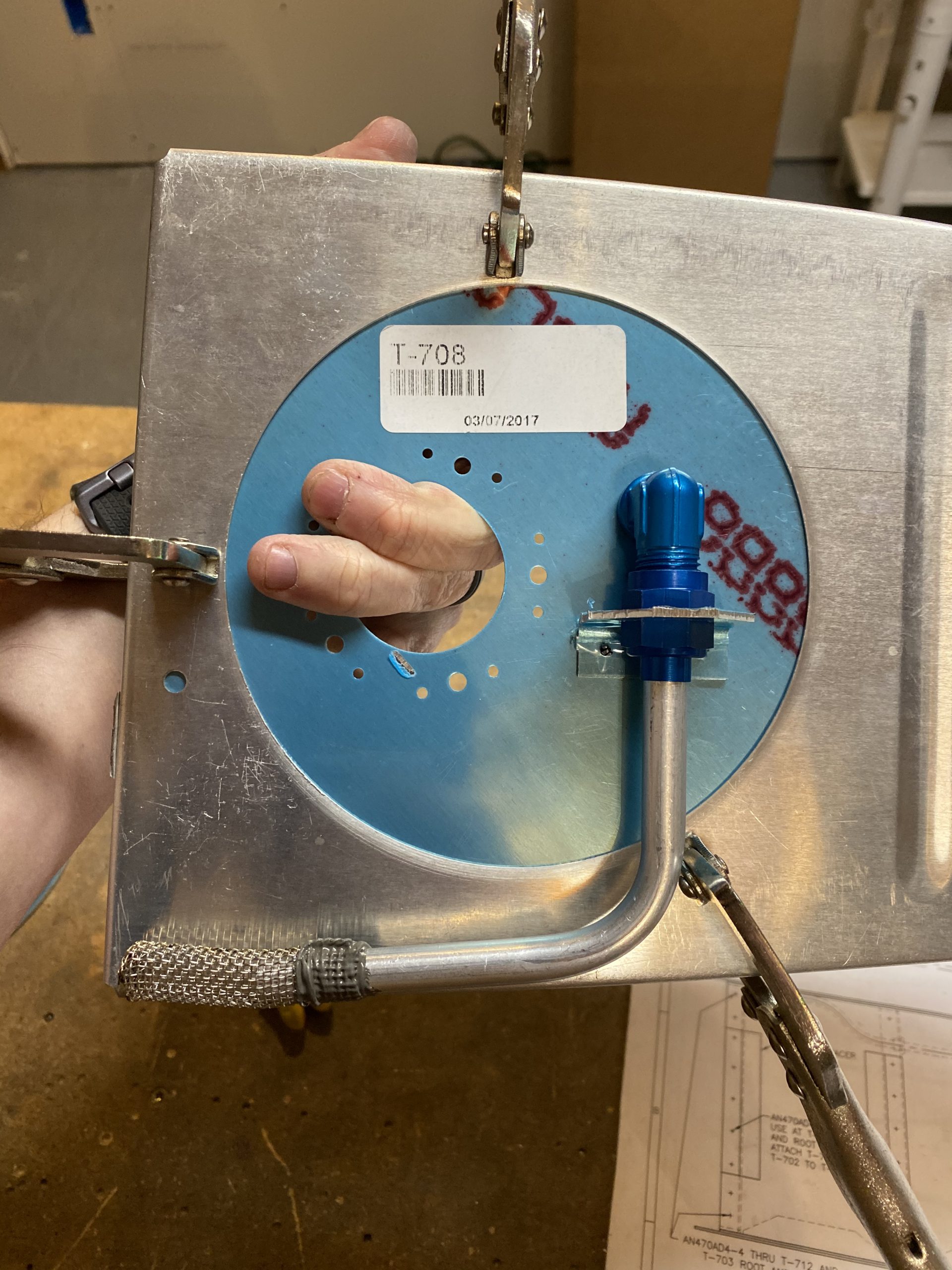
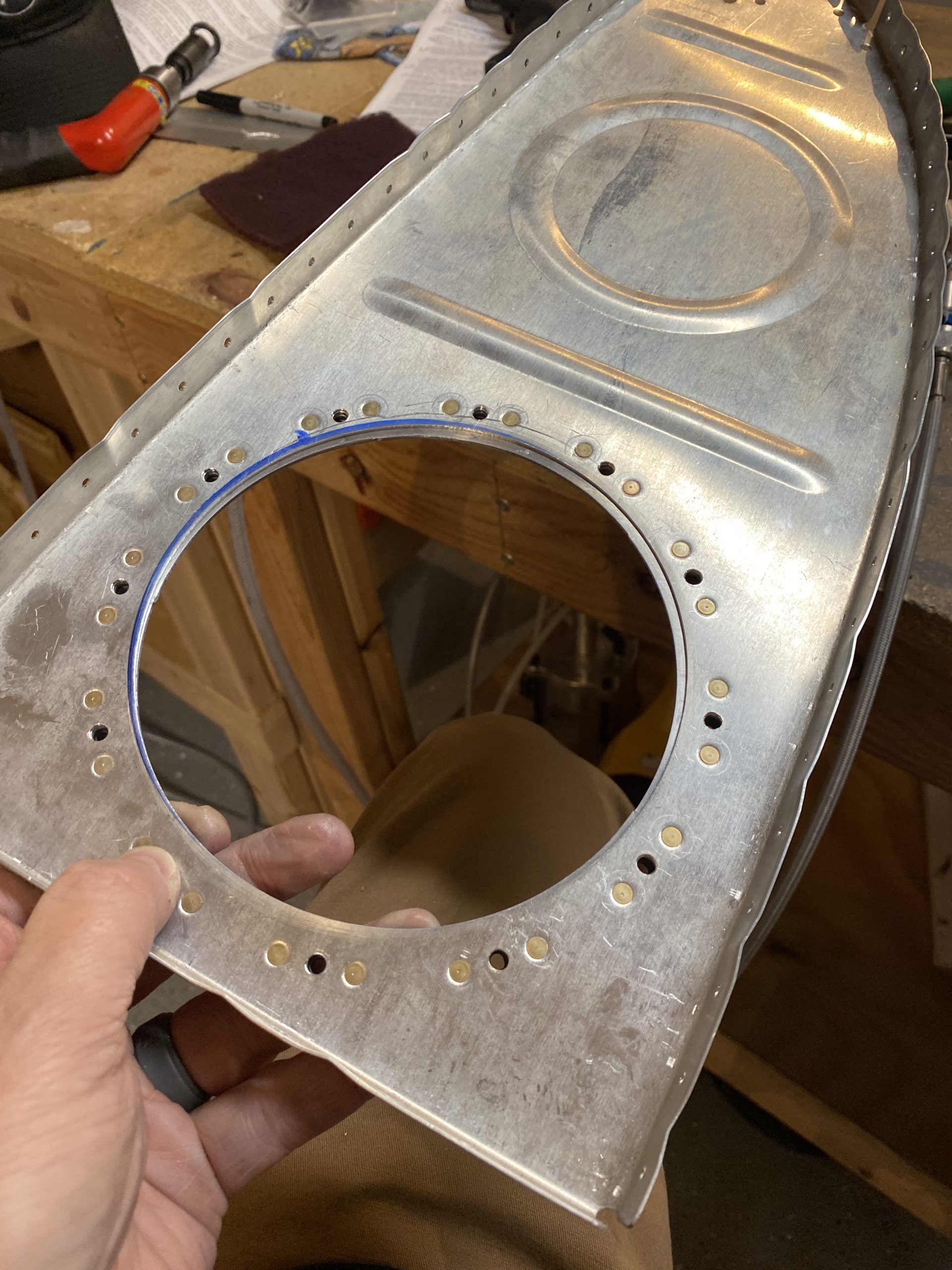
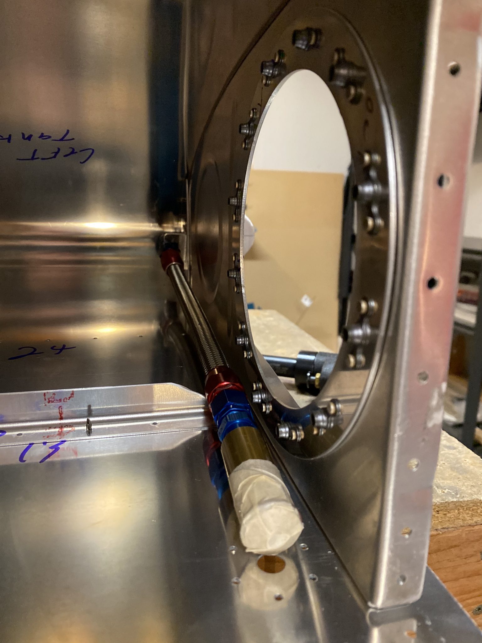
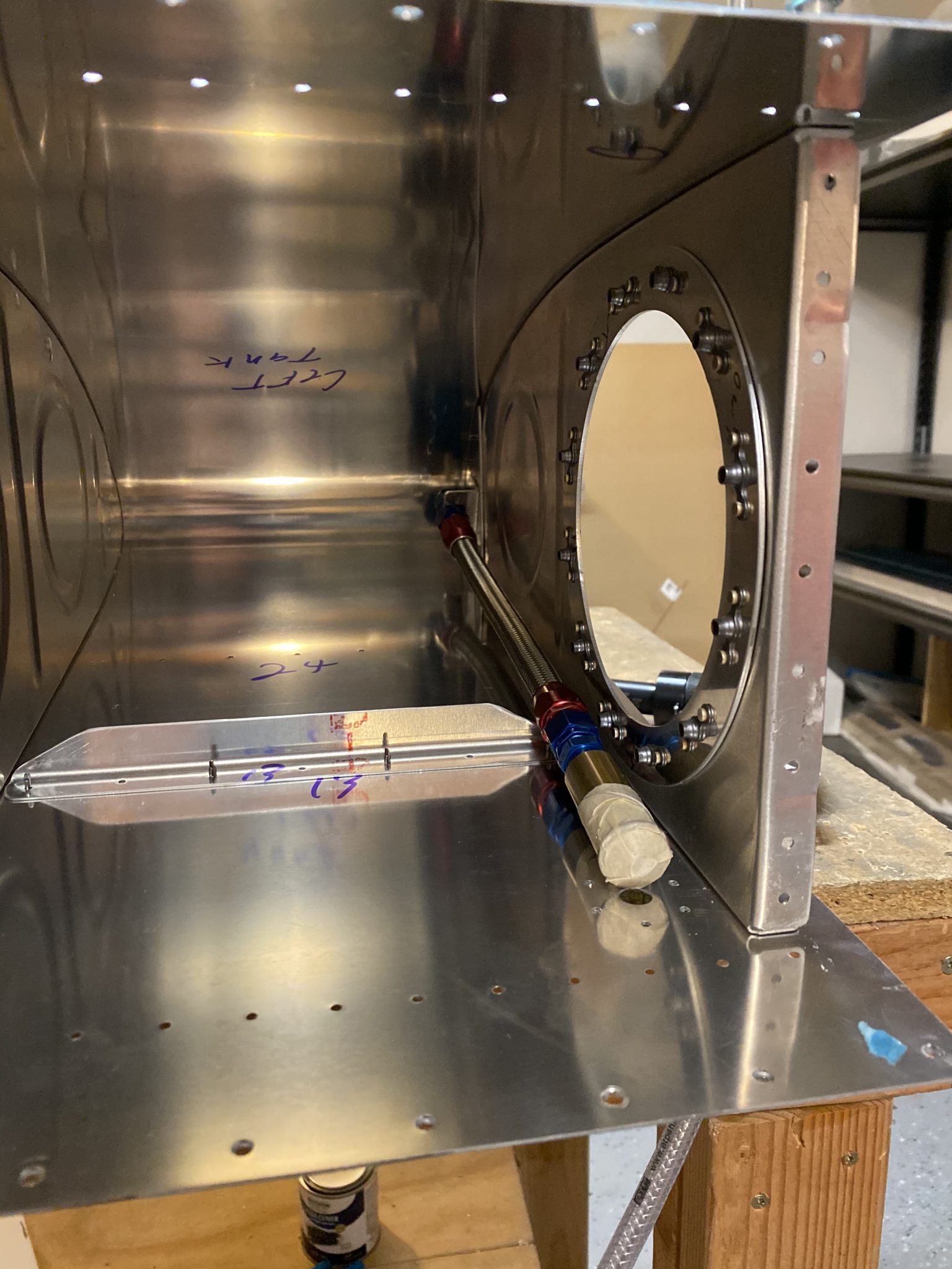
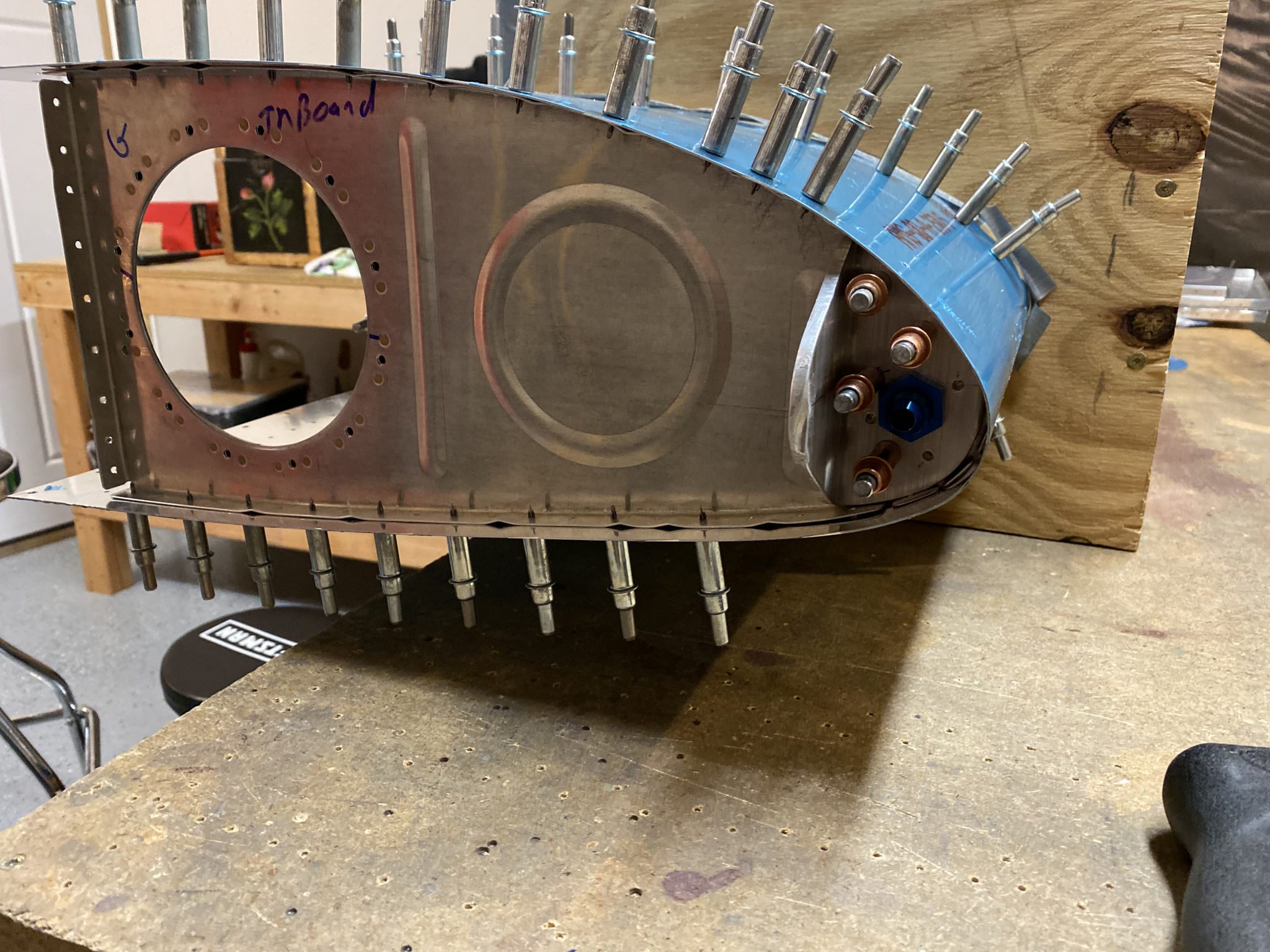
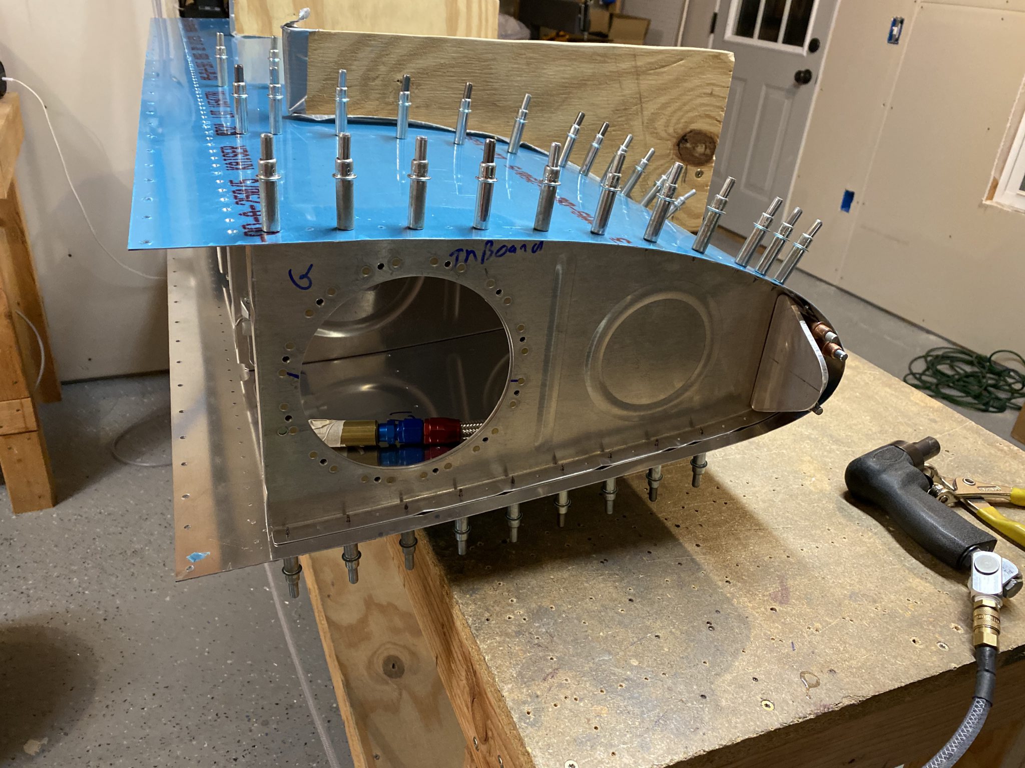
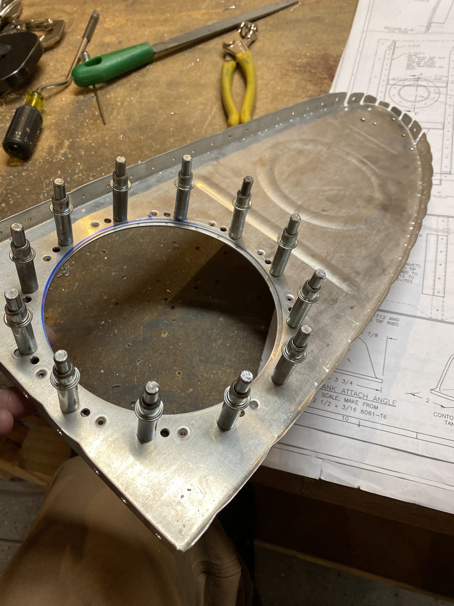
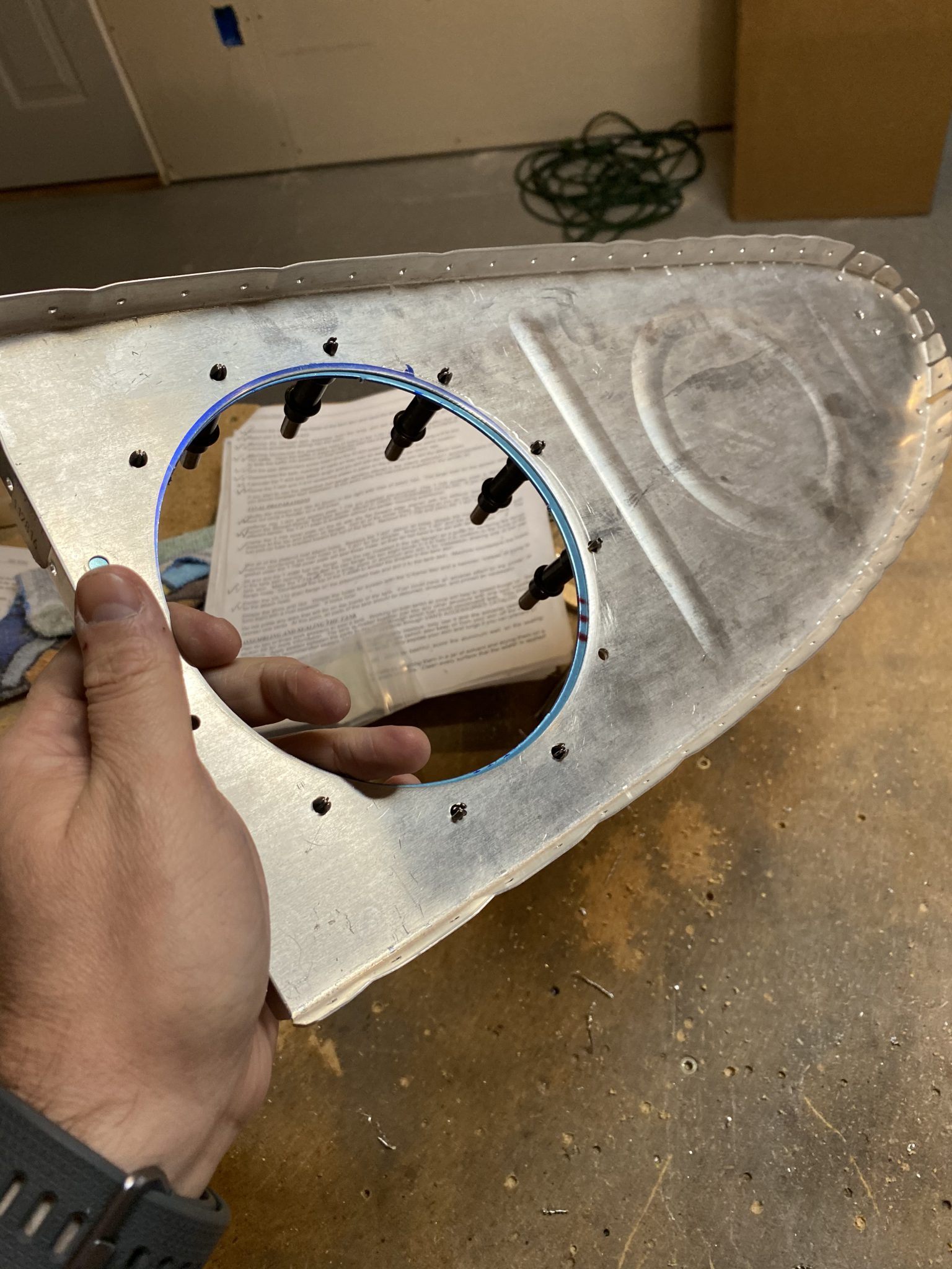
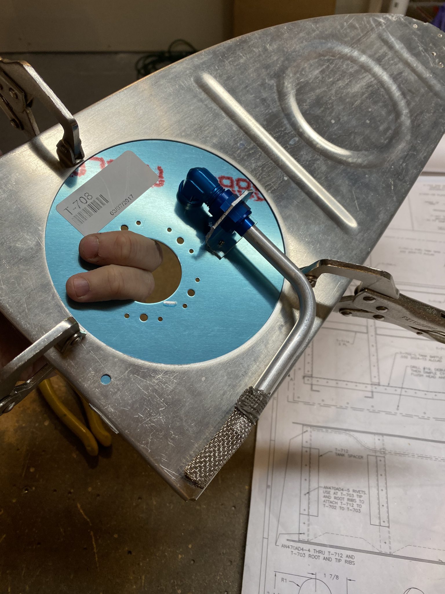
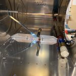
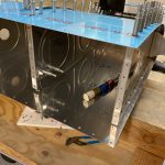
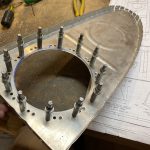
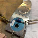
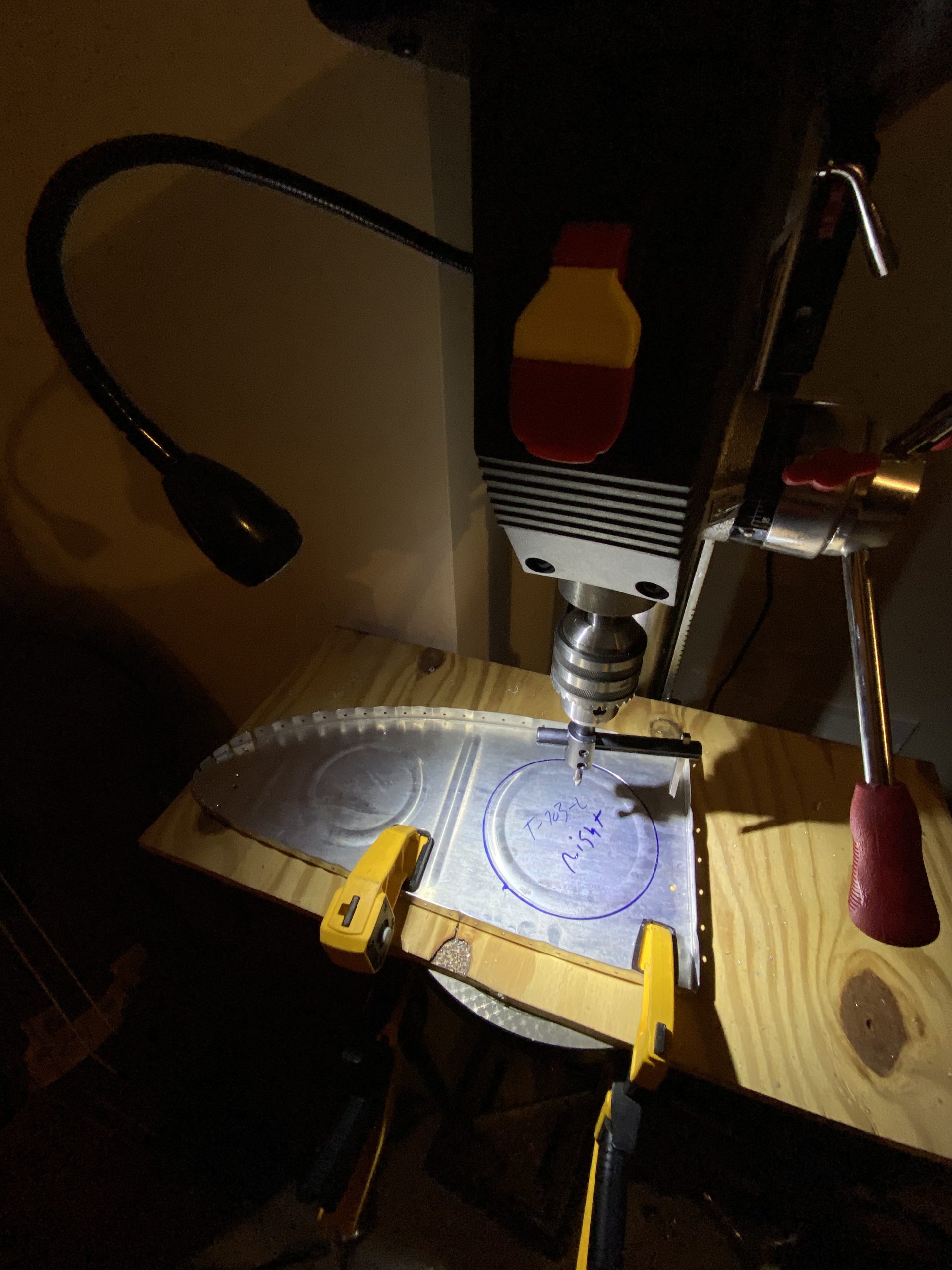
The session starts of with trying to find a good location on the tank attach angle brackets to drill the 9/16″ hole for the flop tube bulkhead fitting. I tried to center mine up as much as possible, while also trying to keep the flop tube as low as possible, but it was a compromise. Here is where I decided:

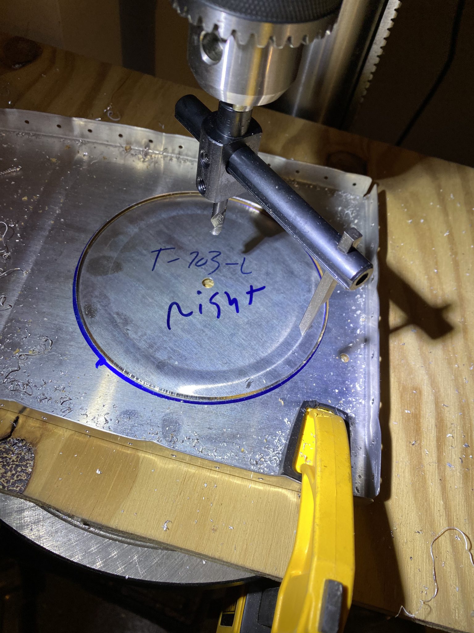
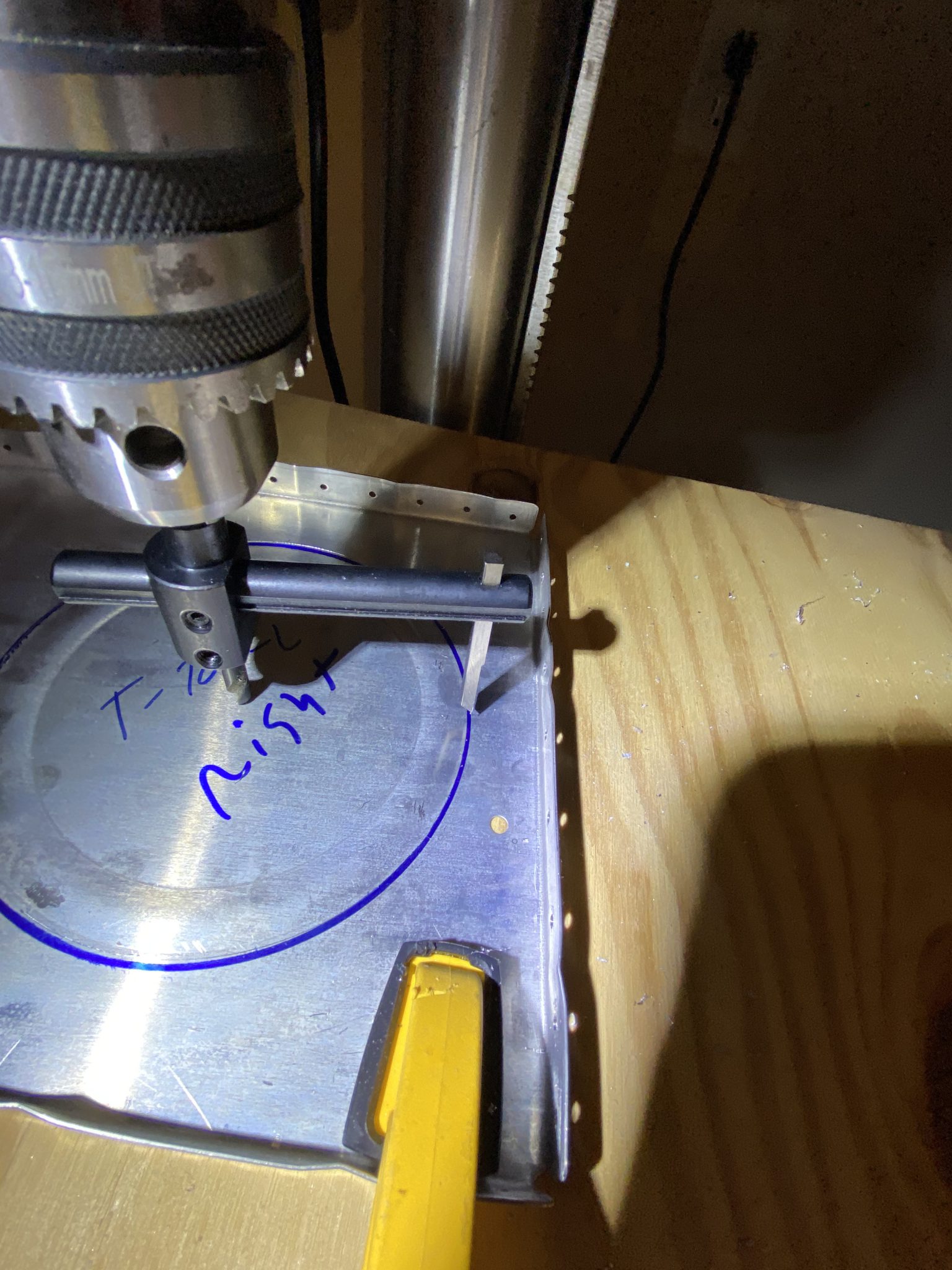
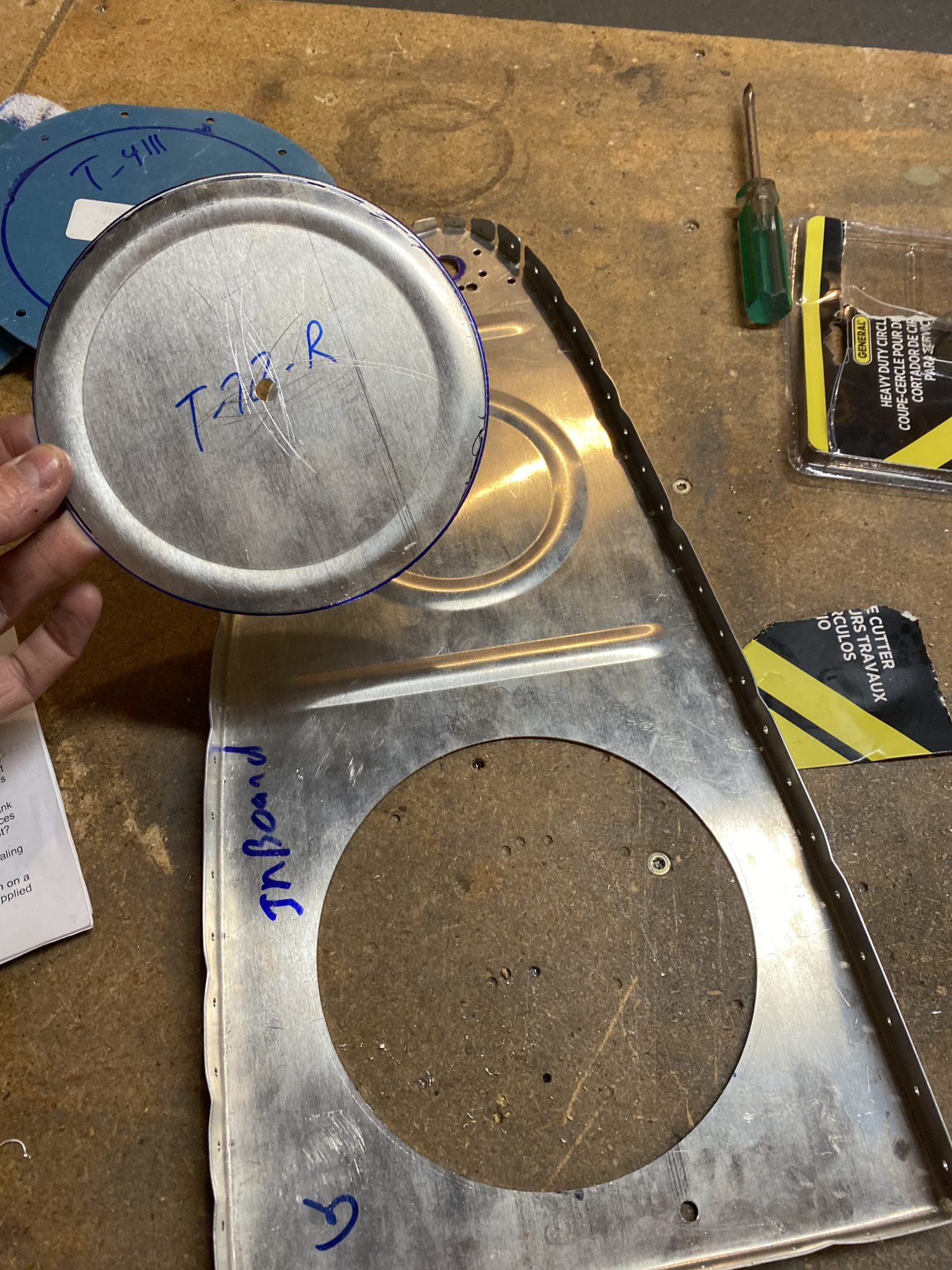
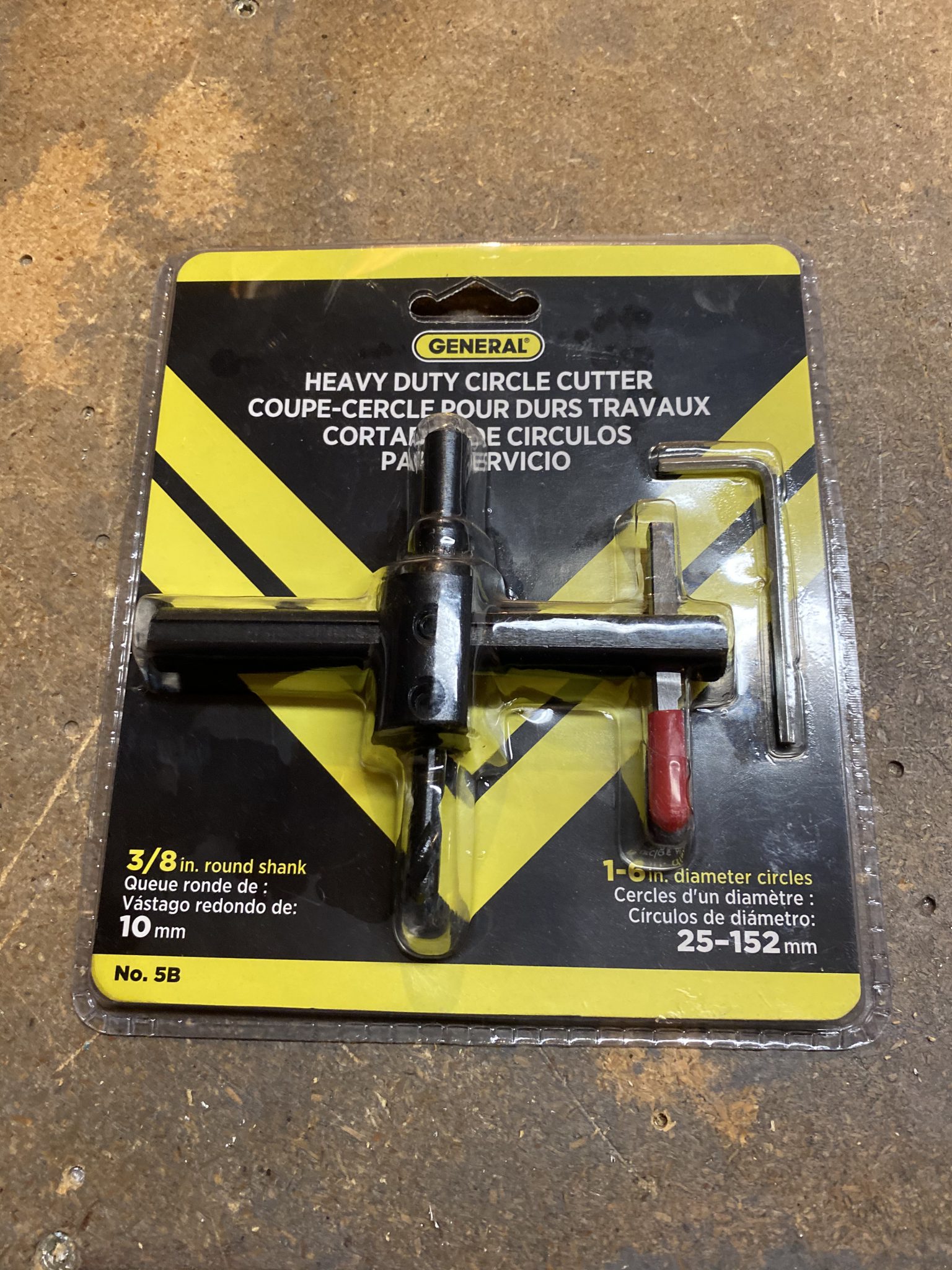
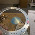
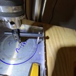
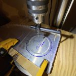
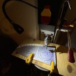
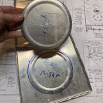
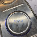
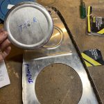
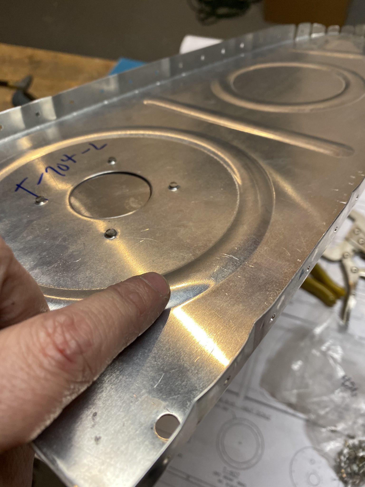
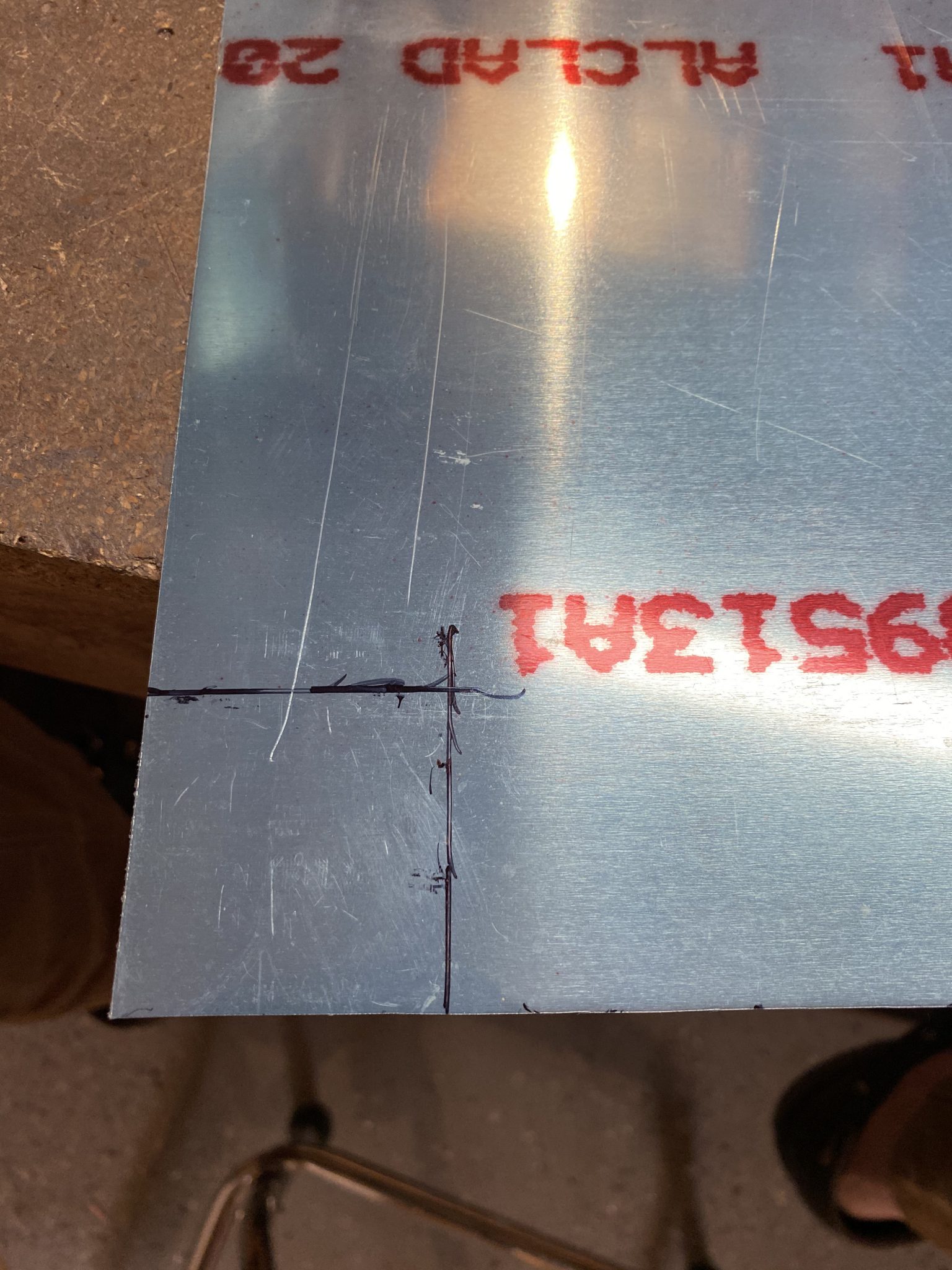
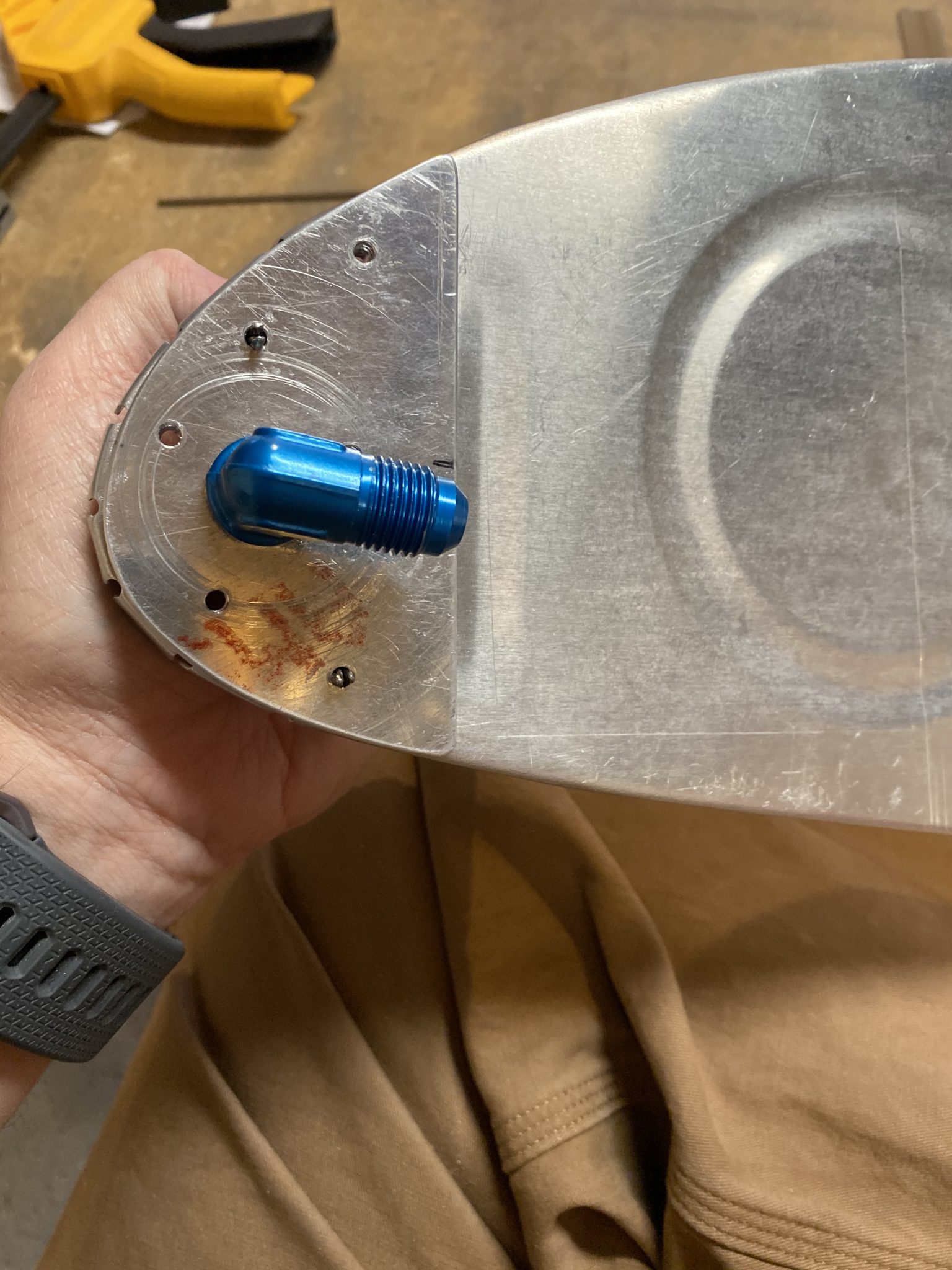
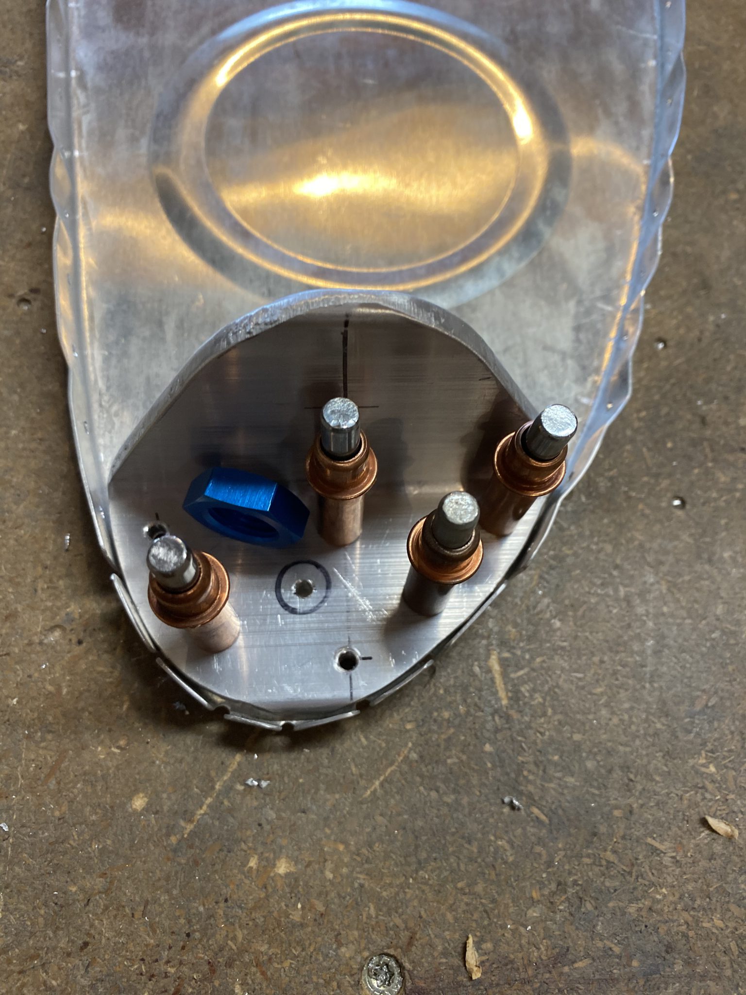
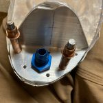
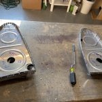
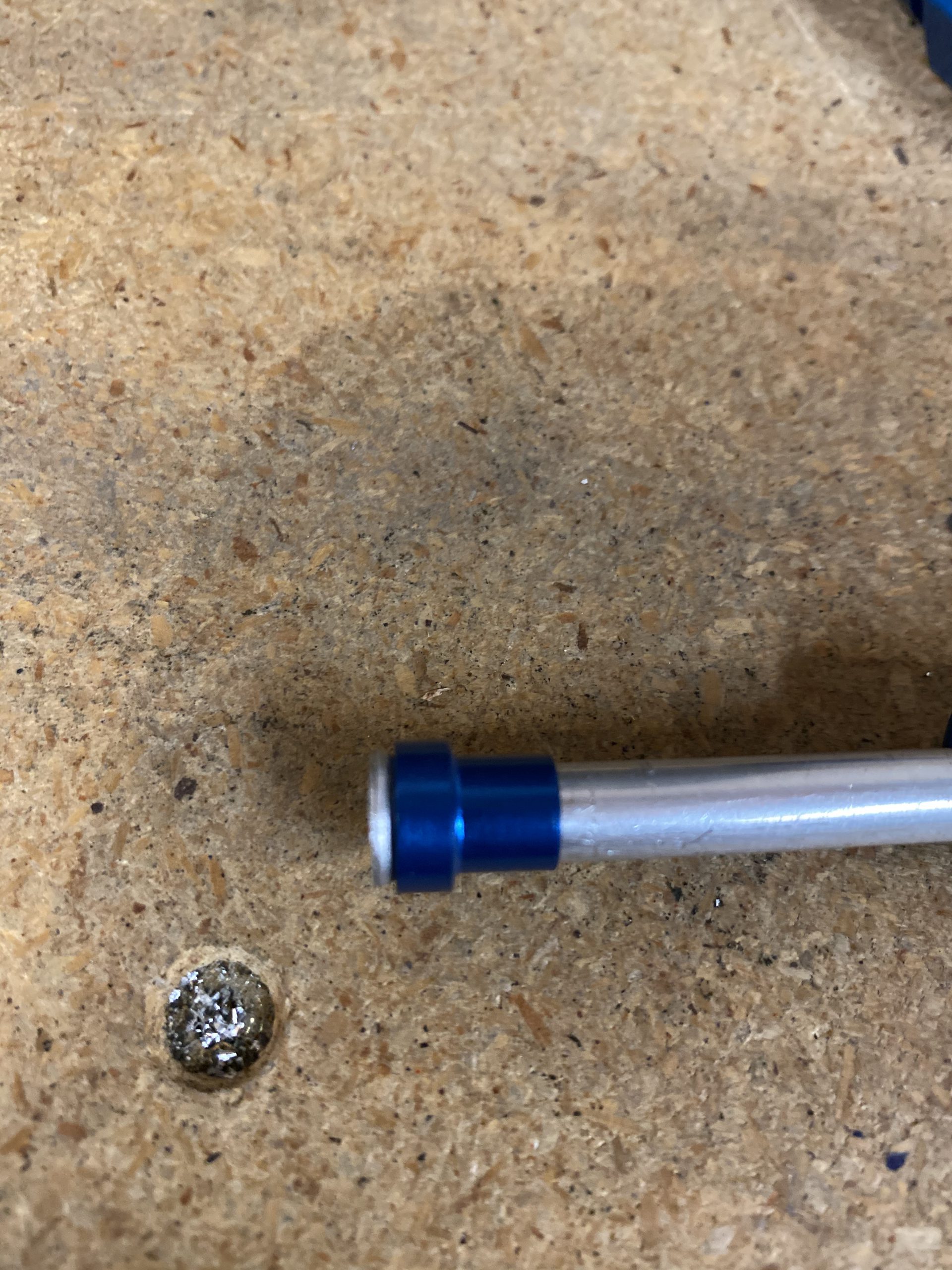
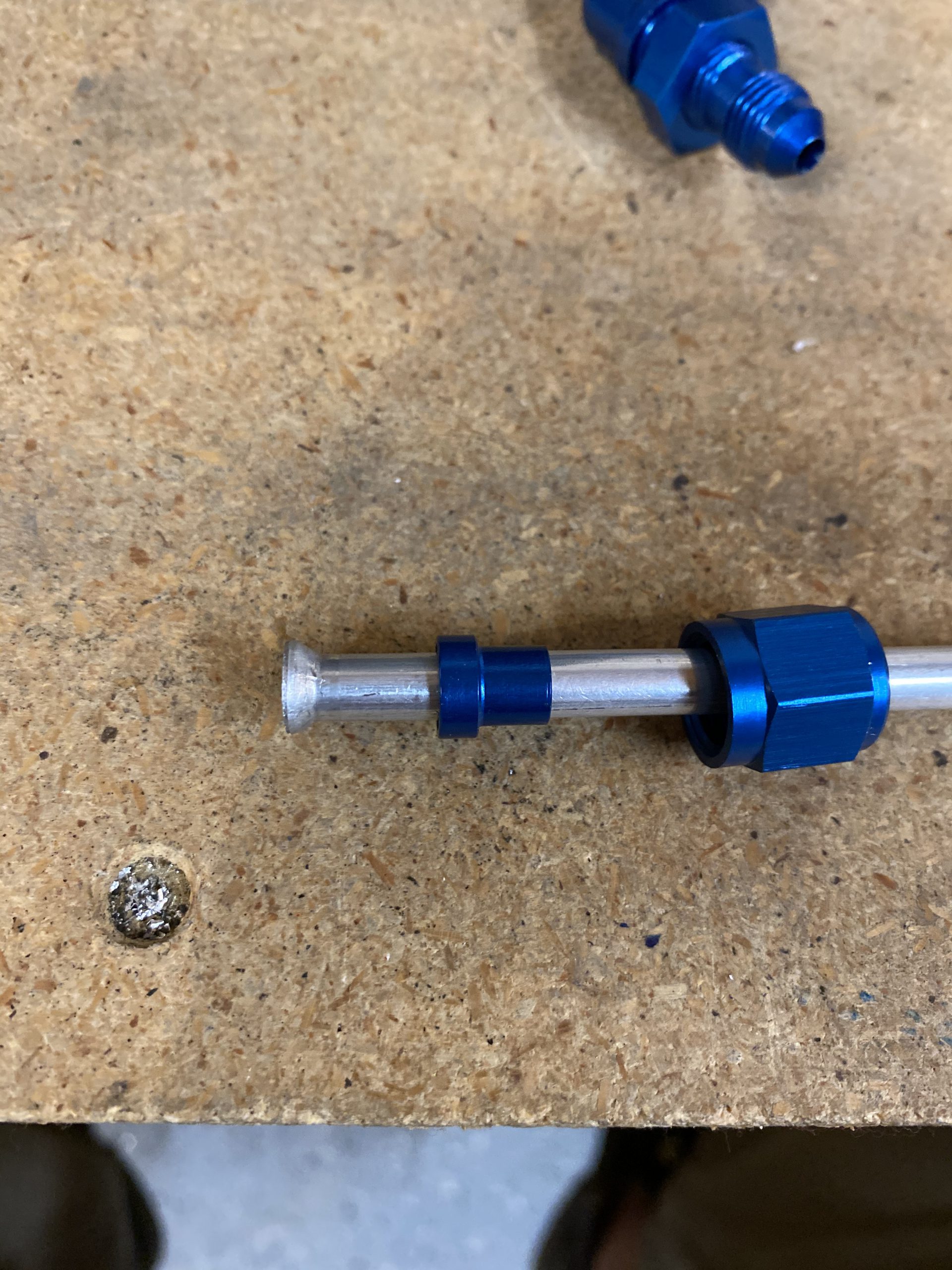
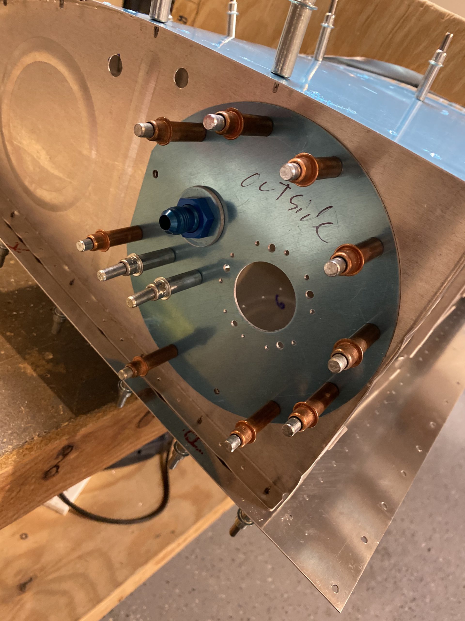
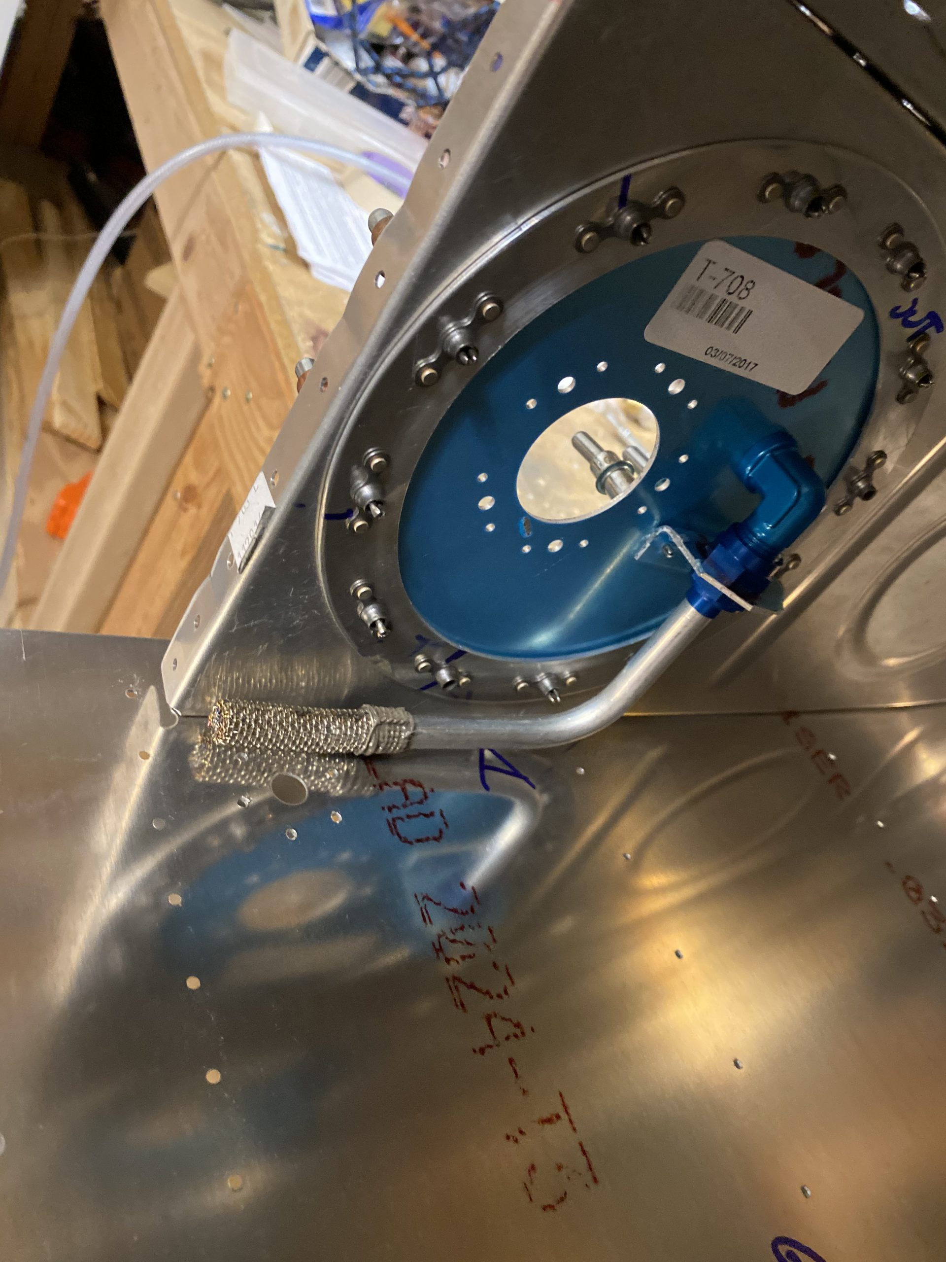
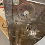
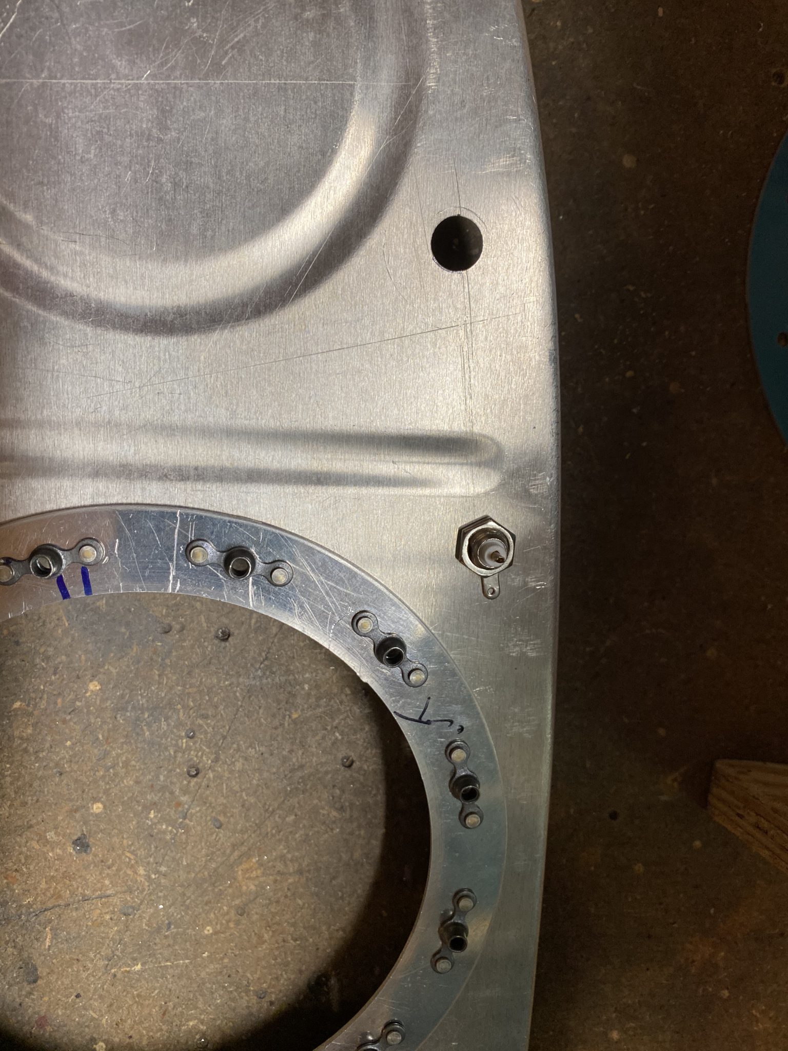
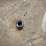
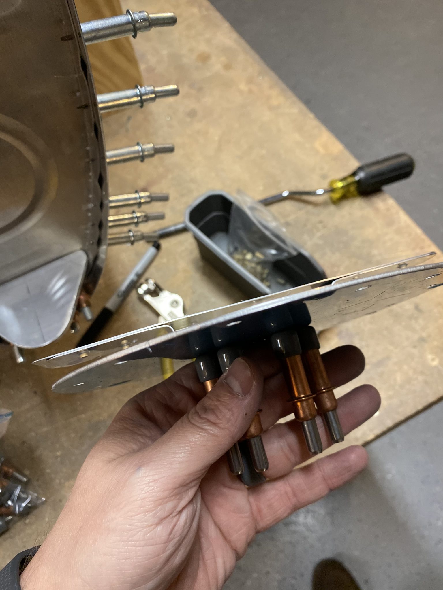
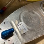
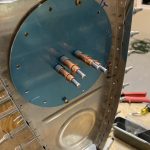
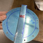
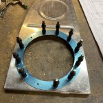
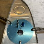
I made a circle using the inside of the blue bulkhead nut as my guide to find a spot. Then I drilled a pilot hole using a #30 bit. This hole went all the way through the T-405 tank attach angles, the T-703-R rib, and the T-410 reinforcement plate. Then, I chucked up my step drill bit in the drill press and drilled the holes out to the proper 9/16″ size.


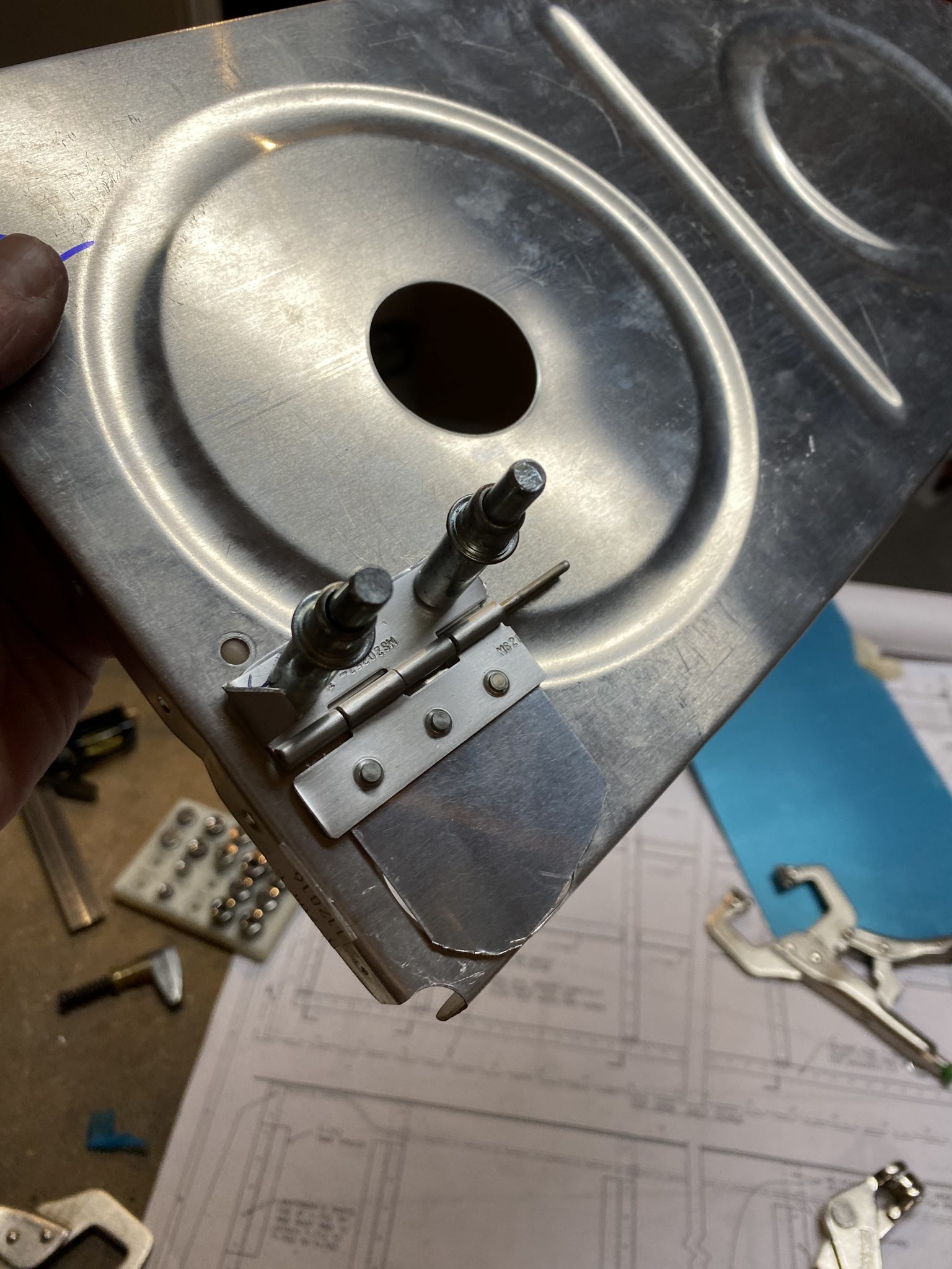
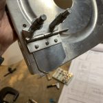
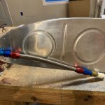
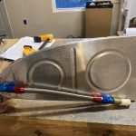
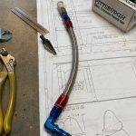
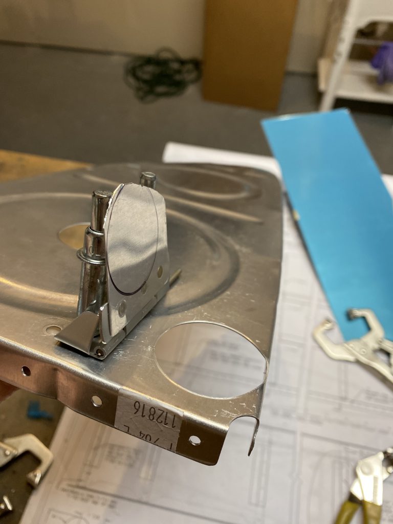
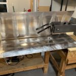
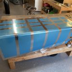
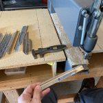
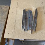
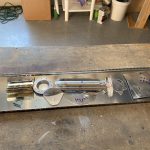
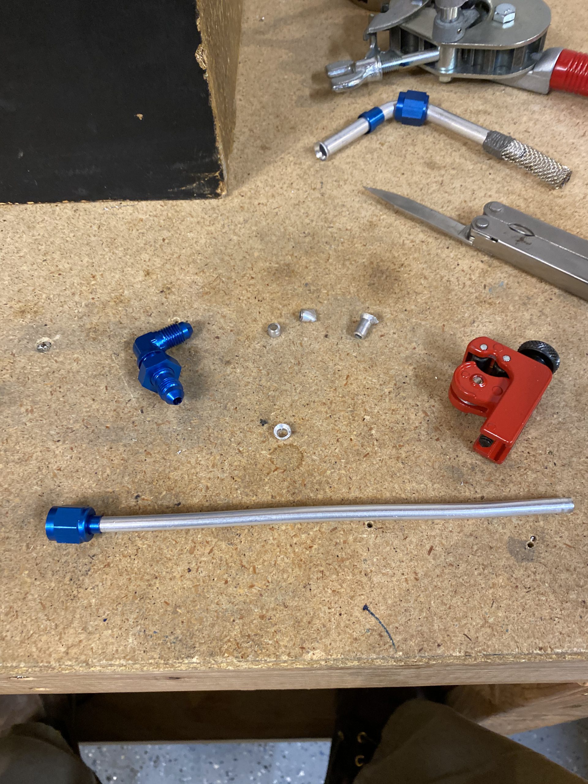
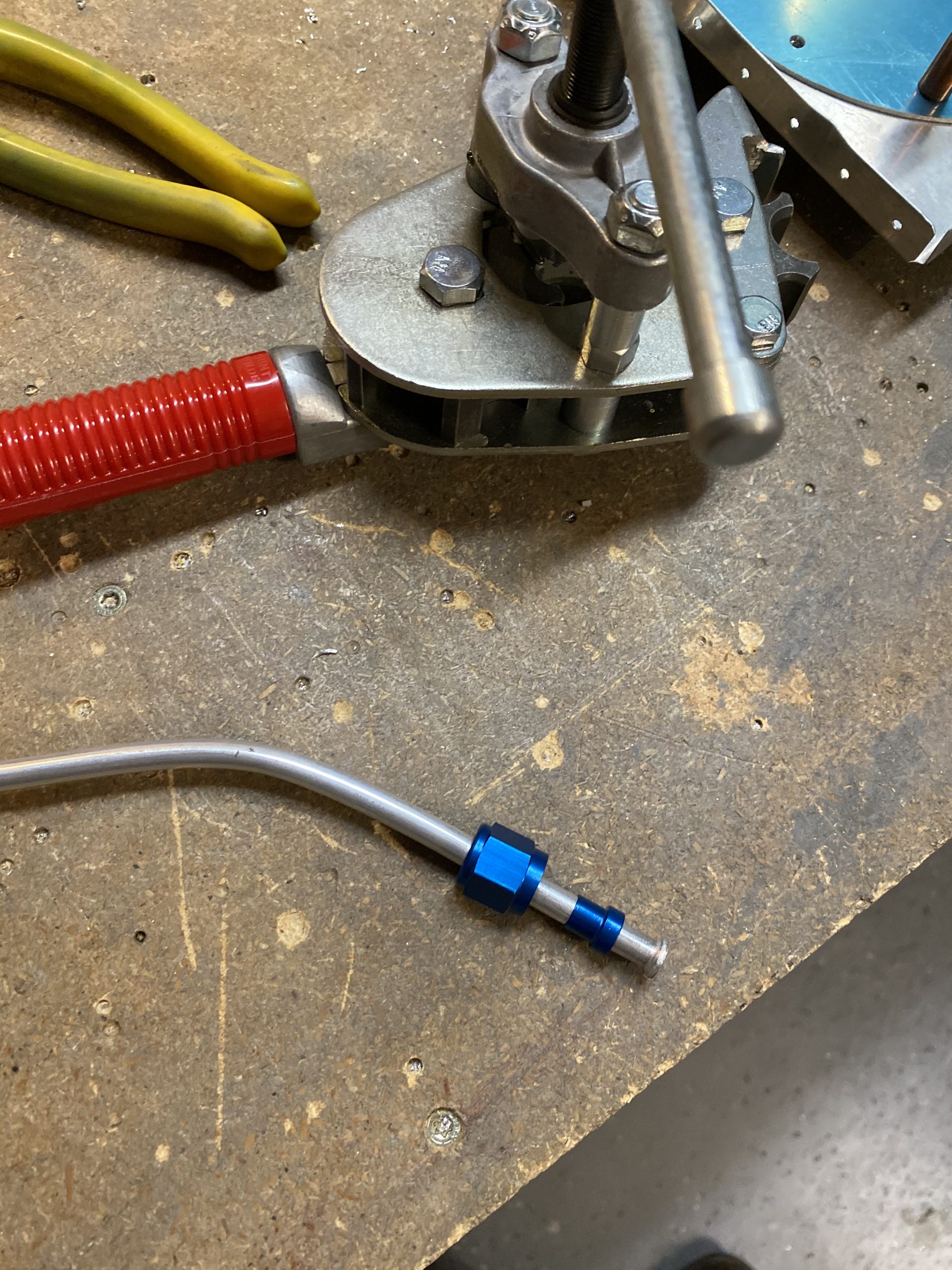
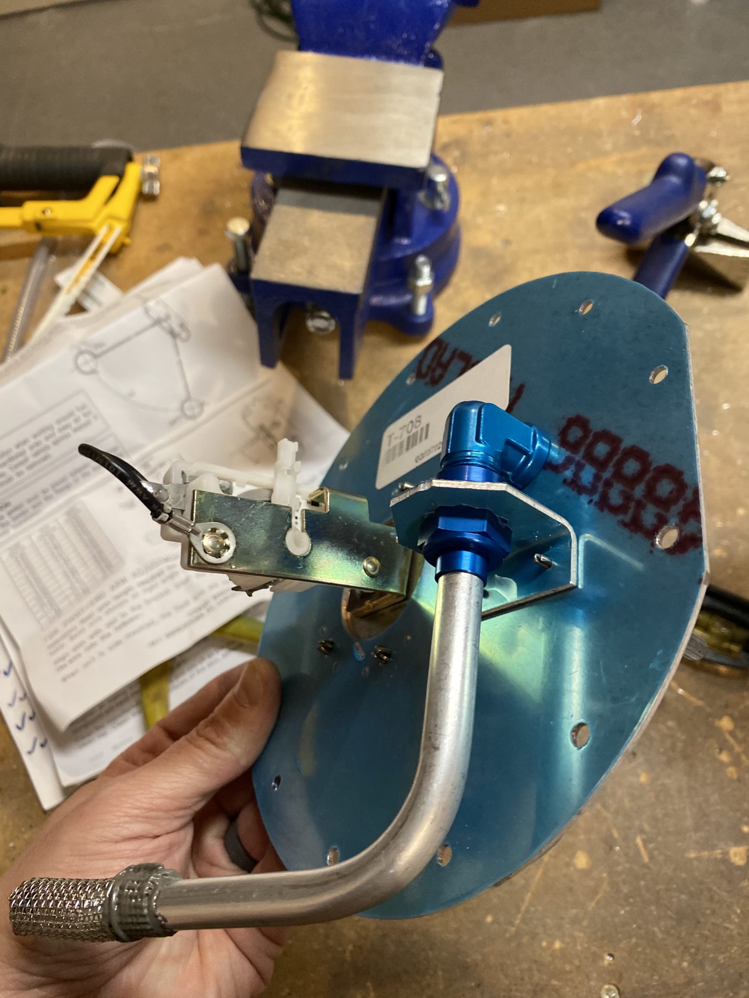
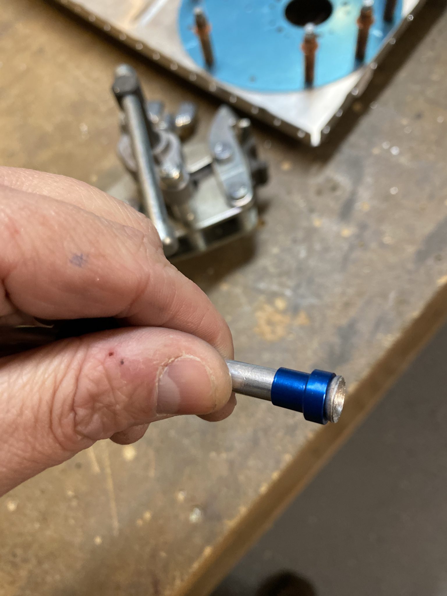
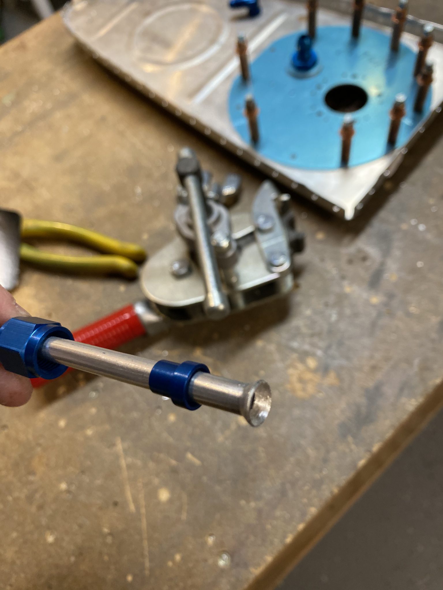
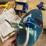
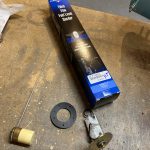
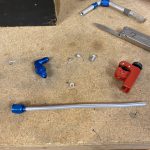
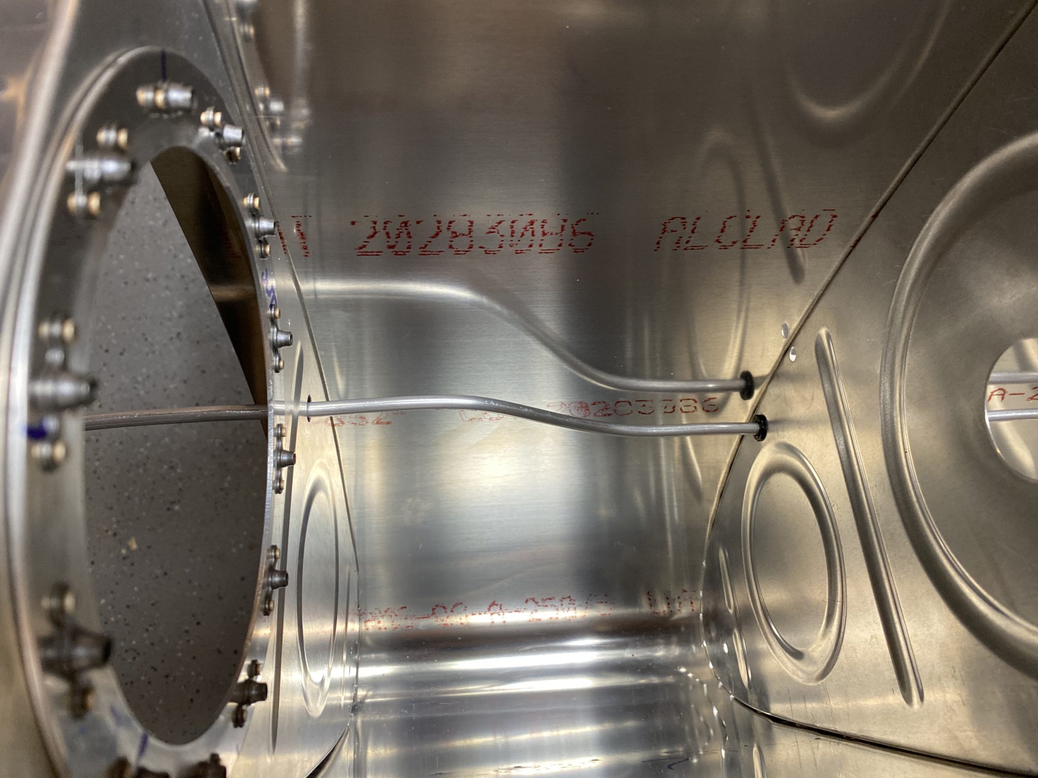
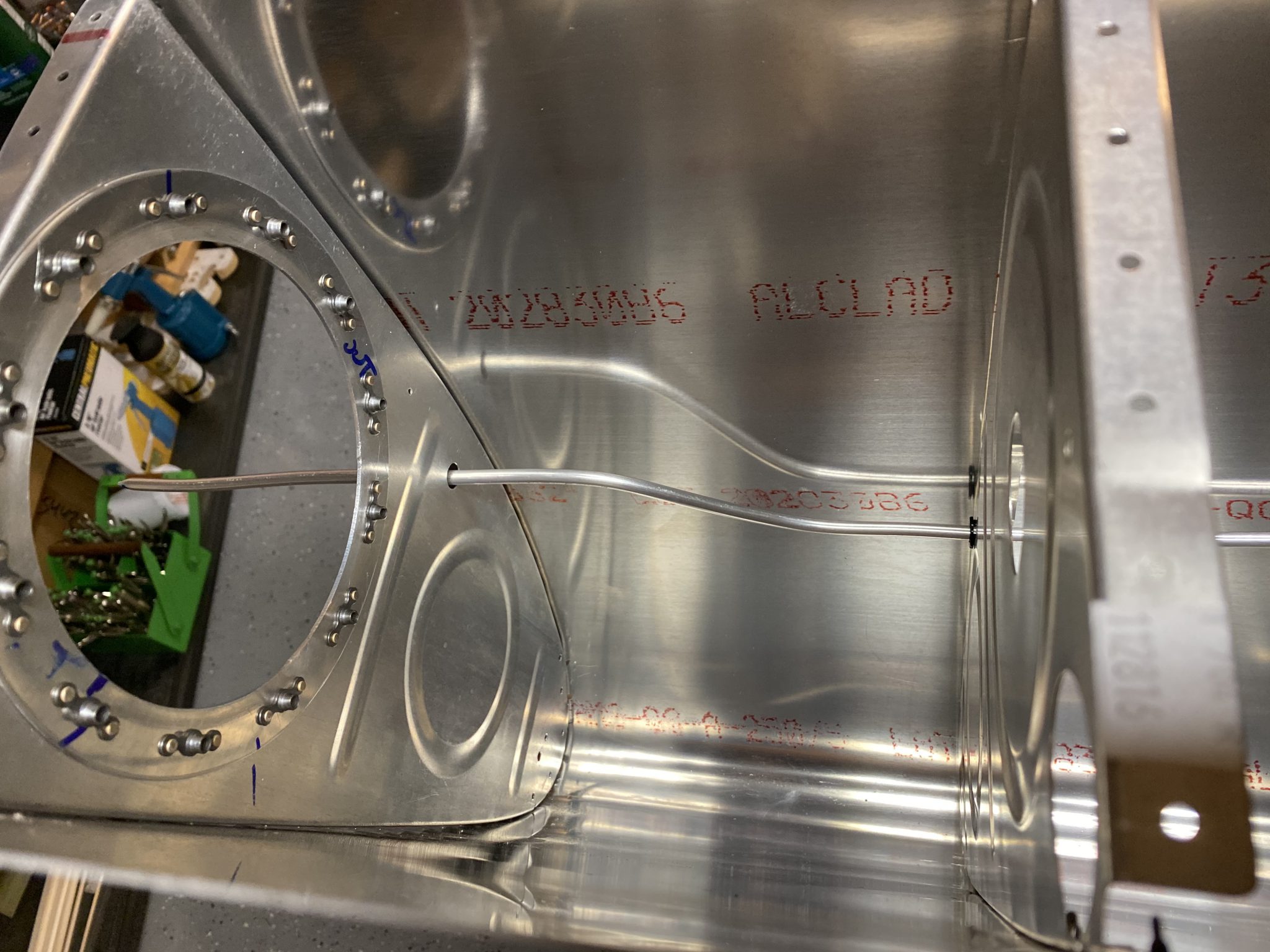
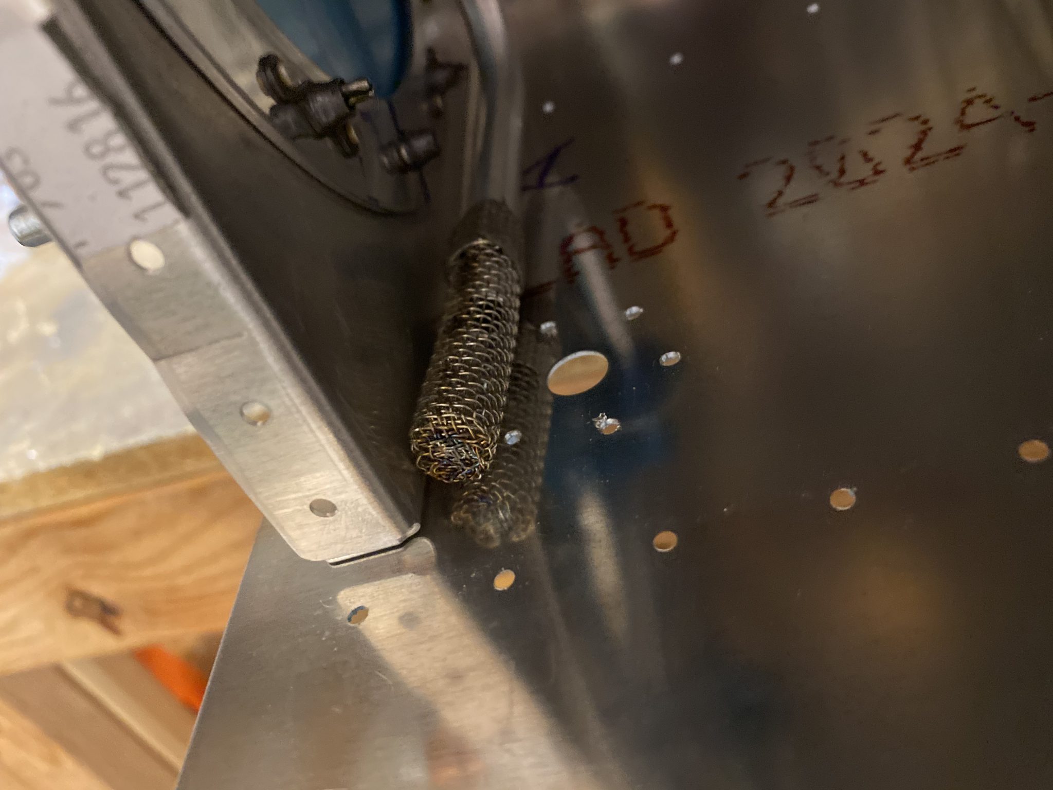
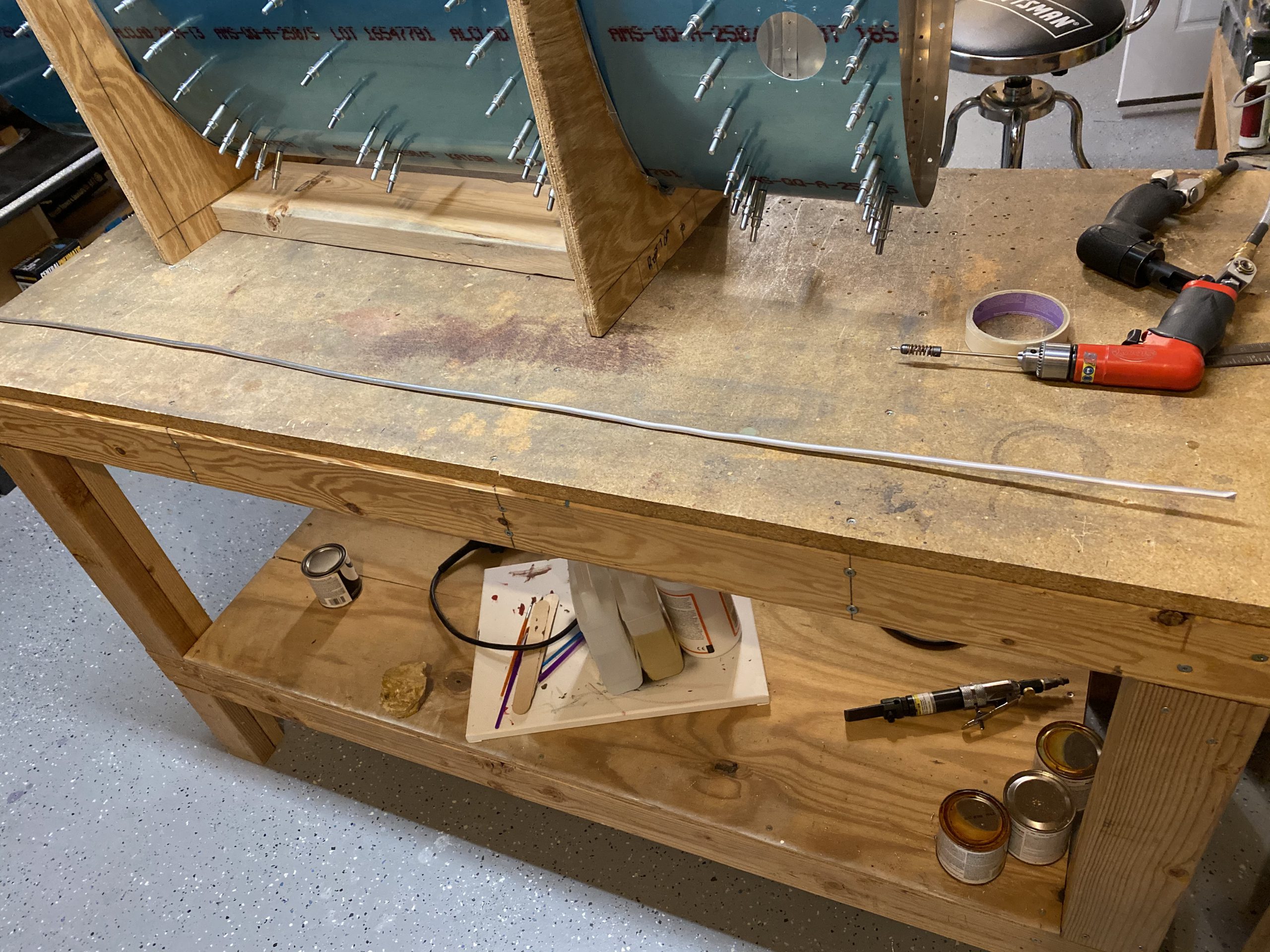
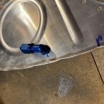
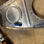
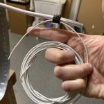
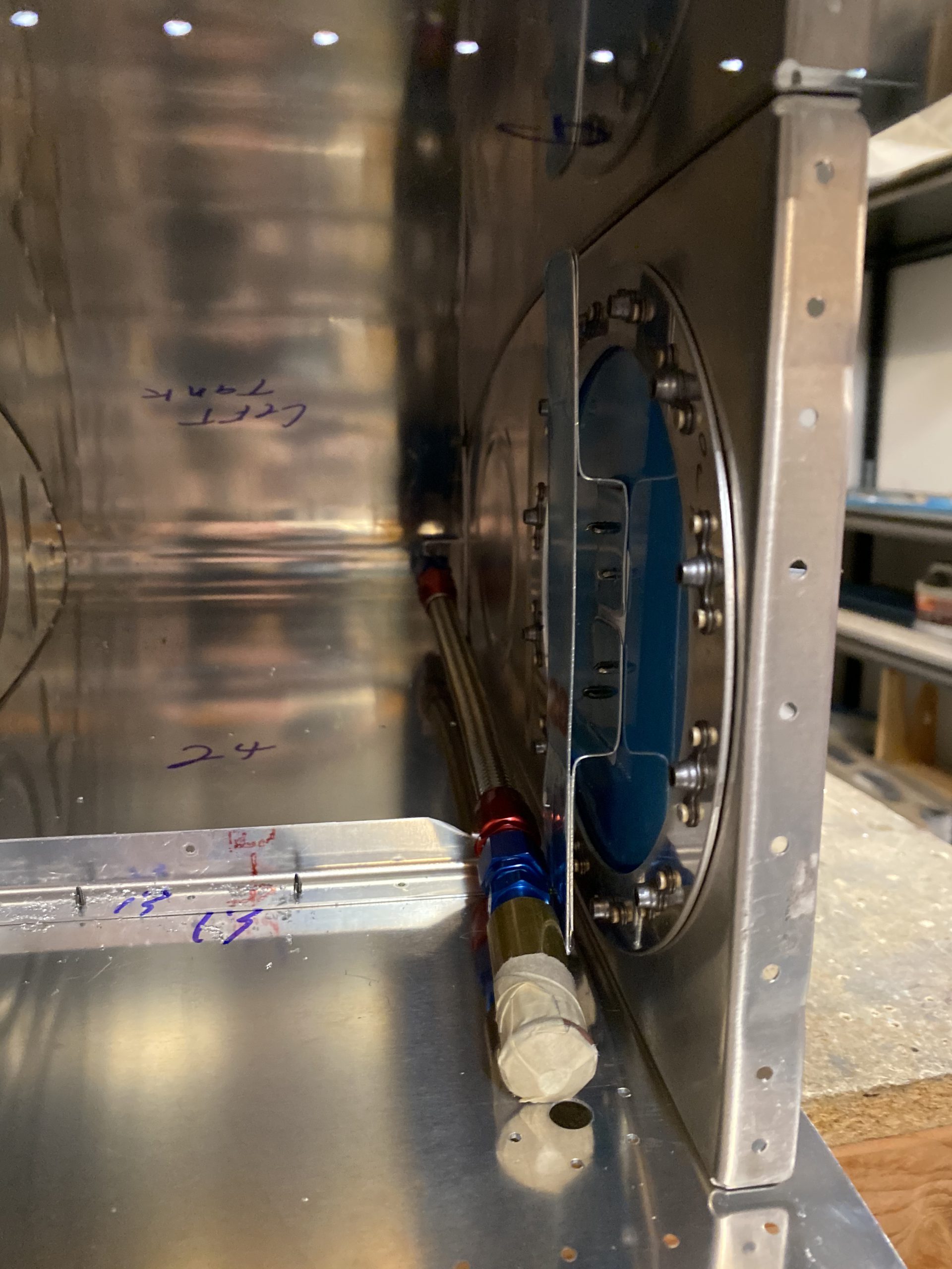
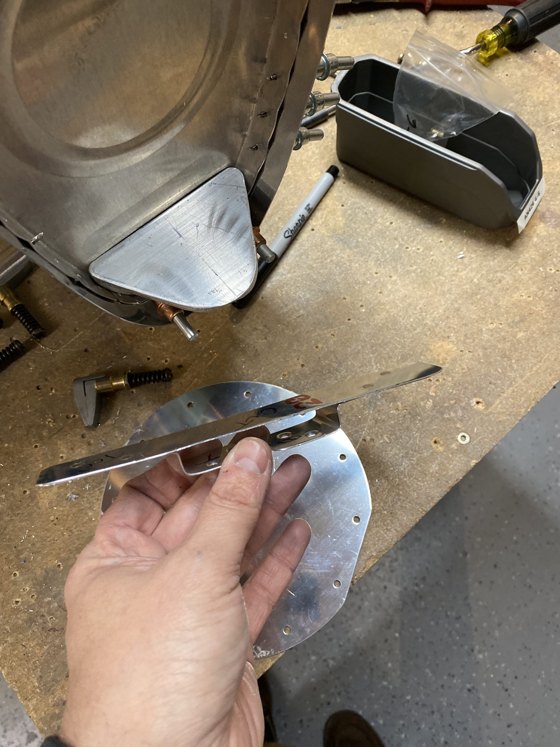
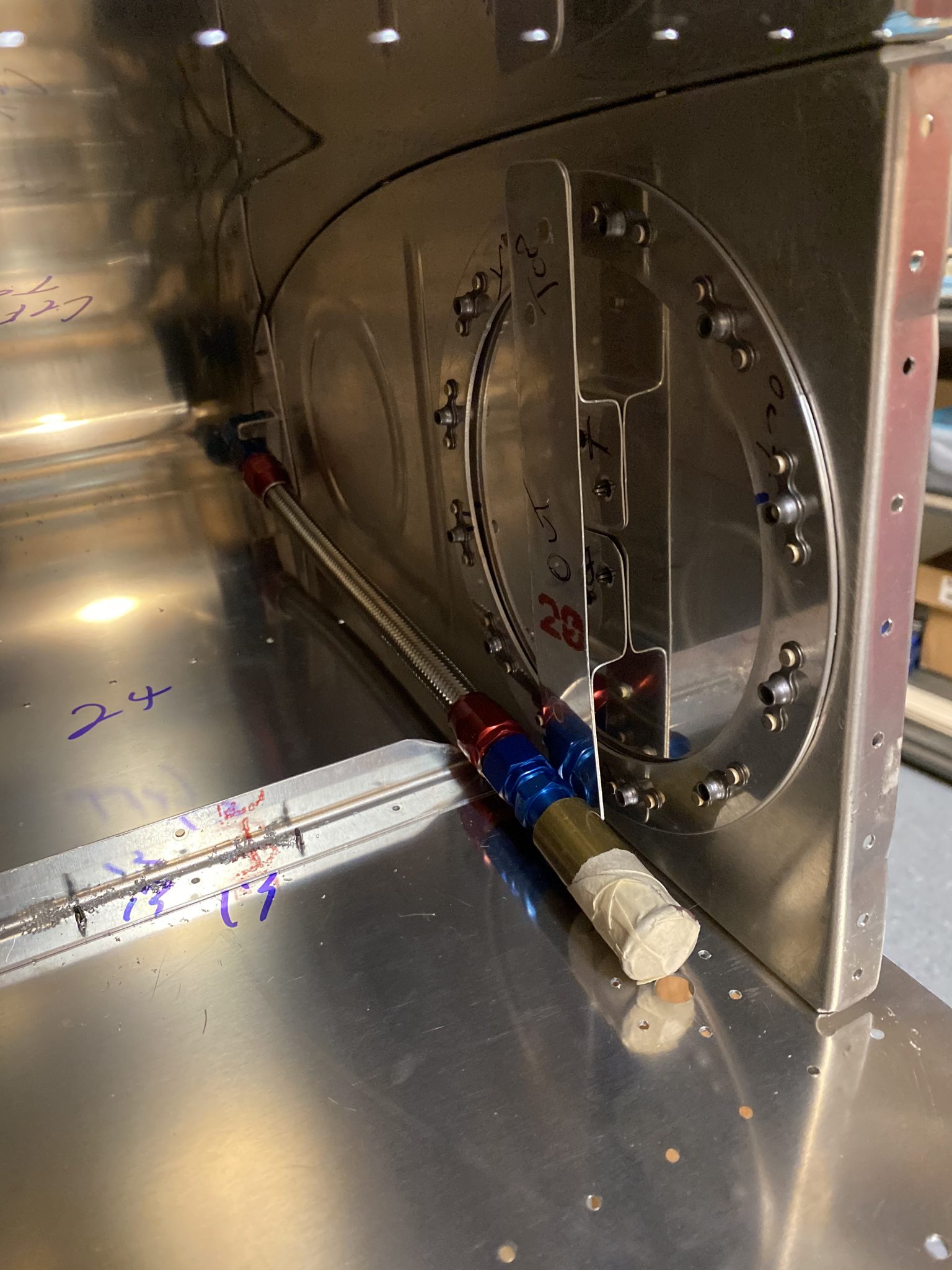
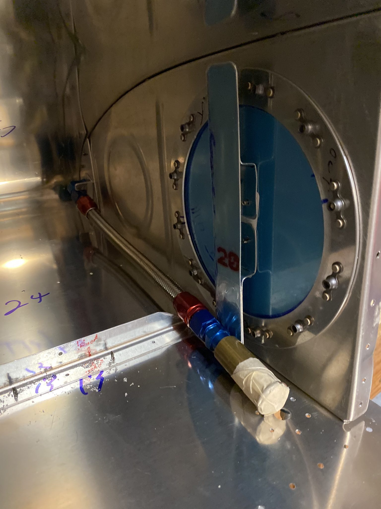
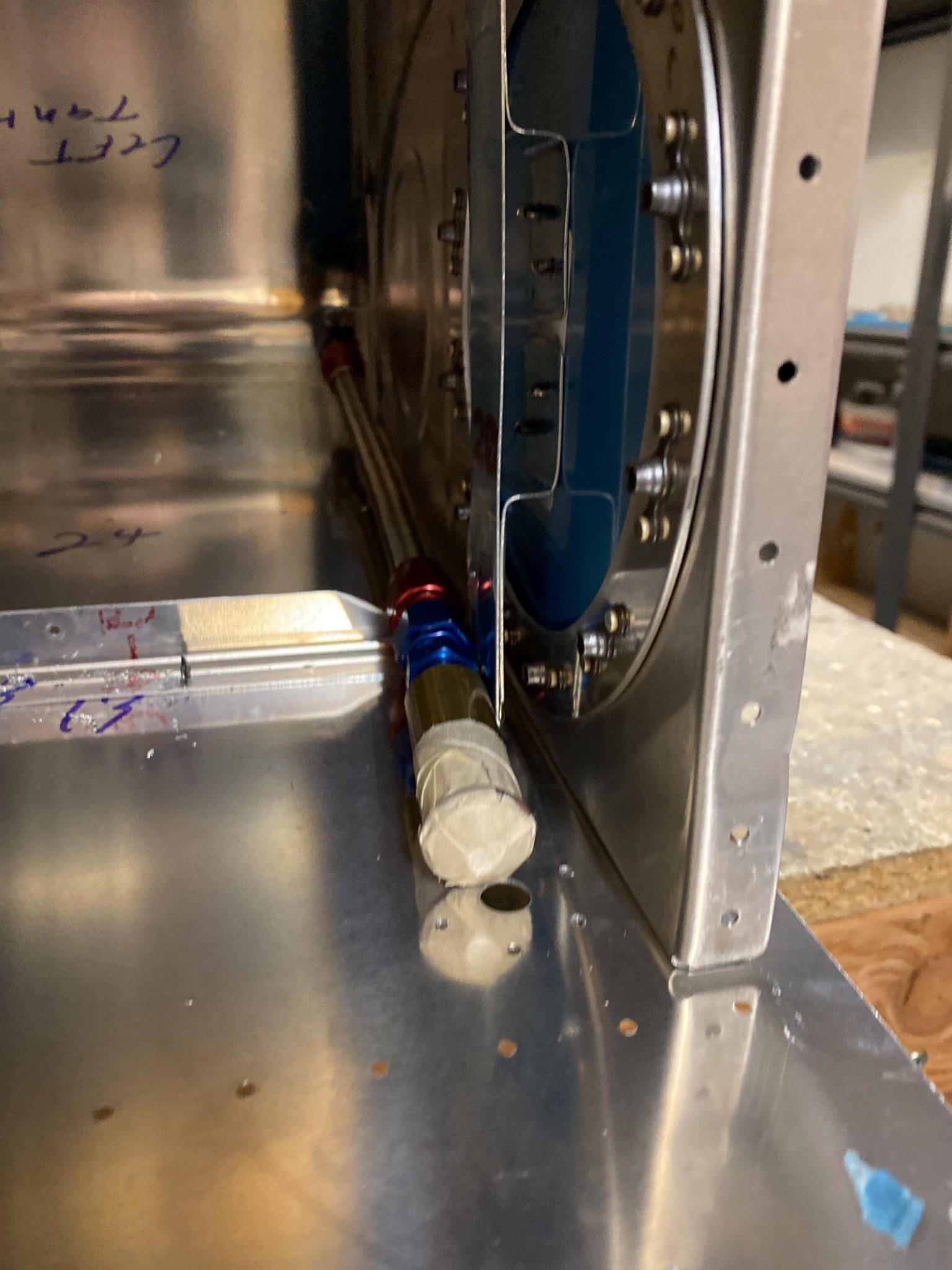
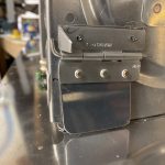
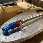
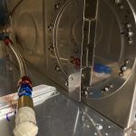
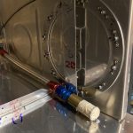
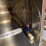
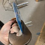
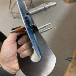
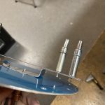
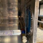
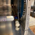
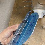
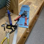
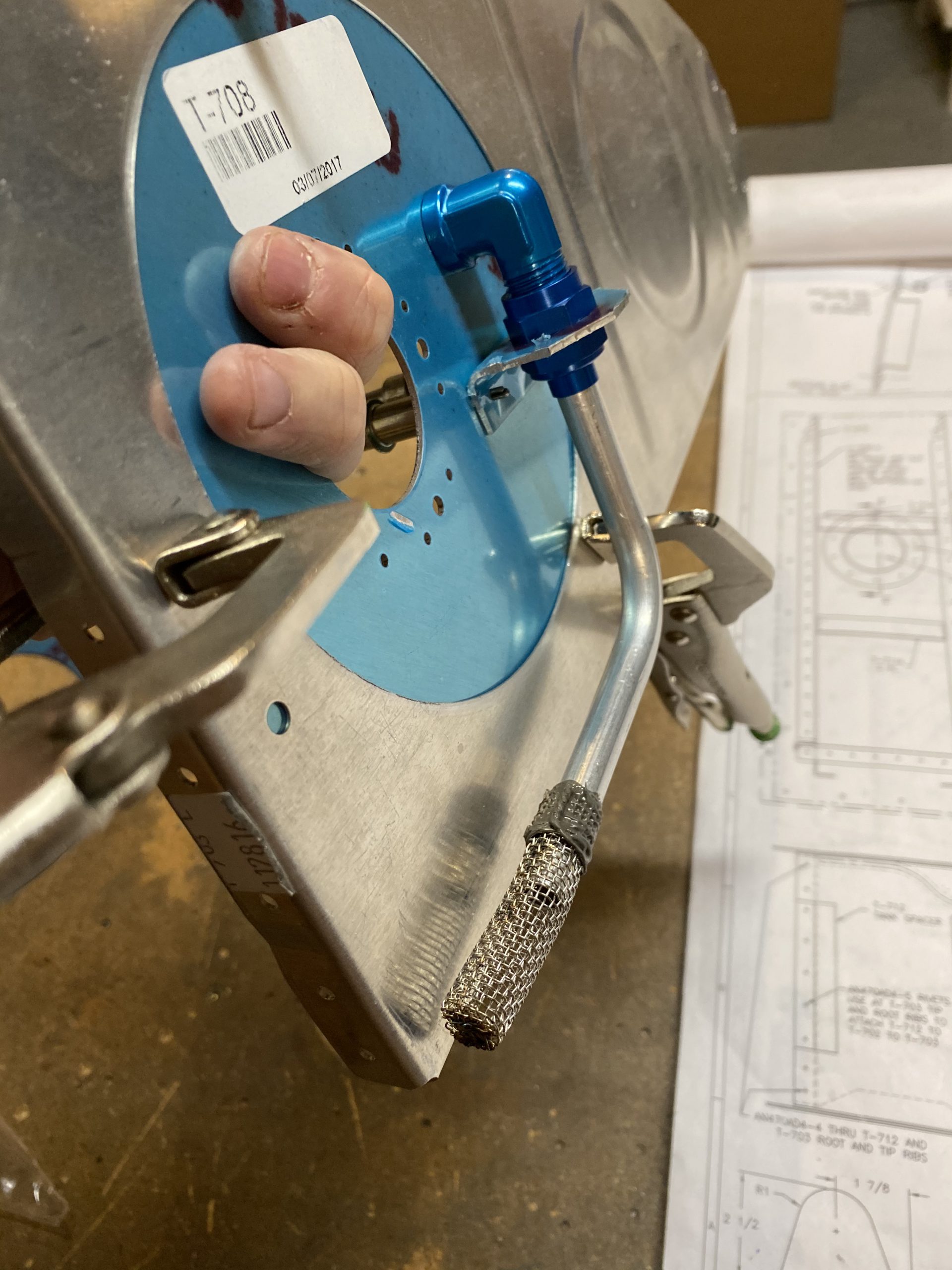
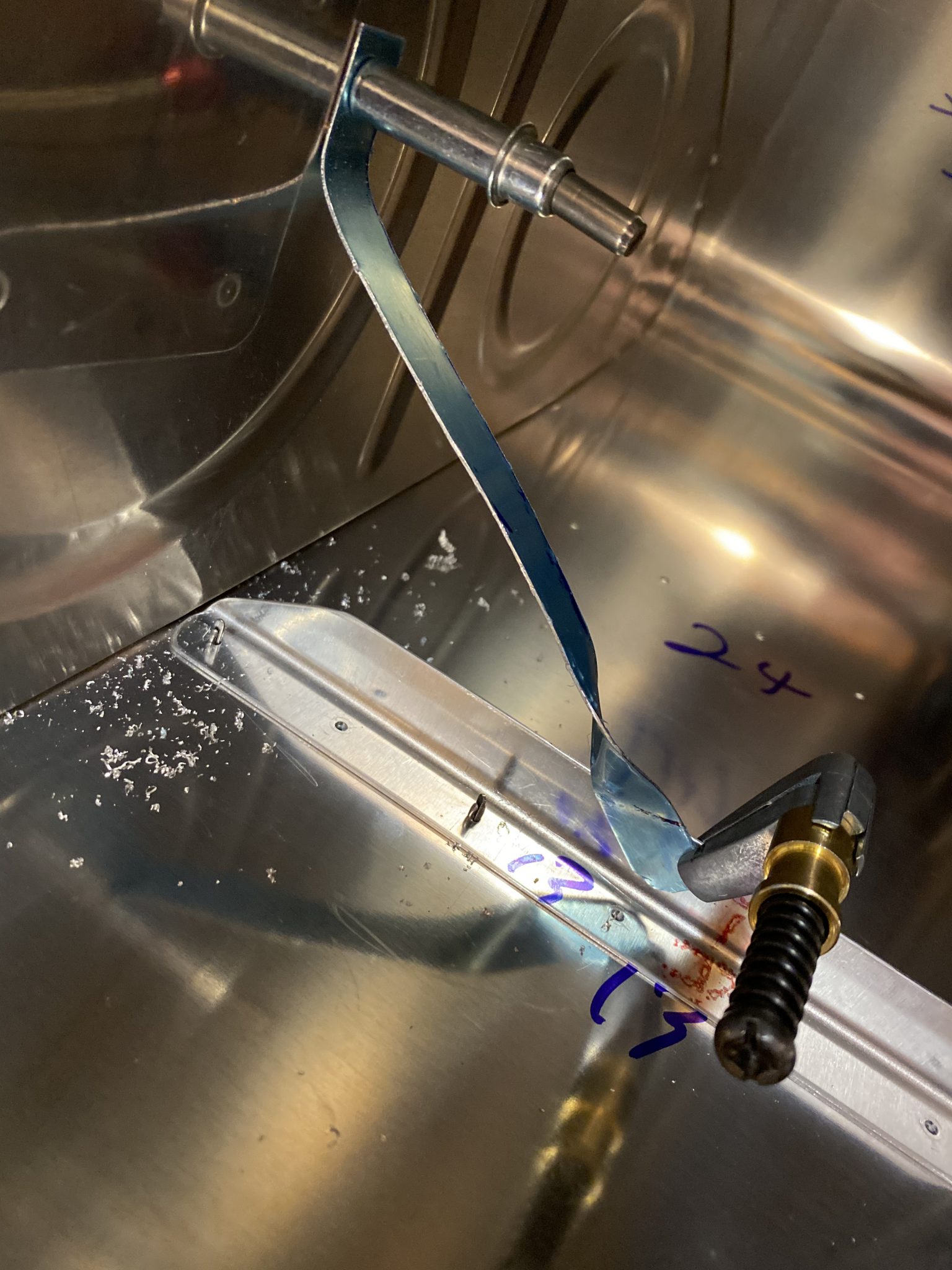
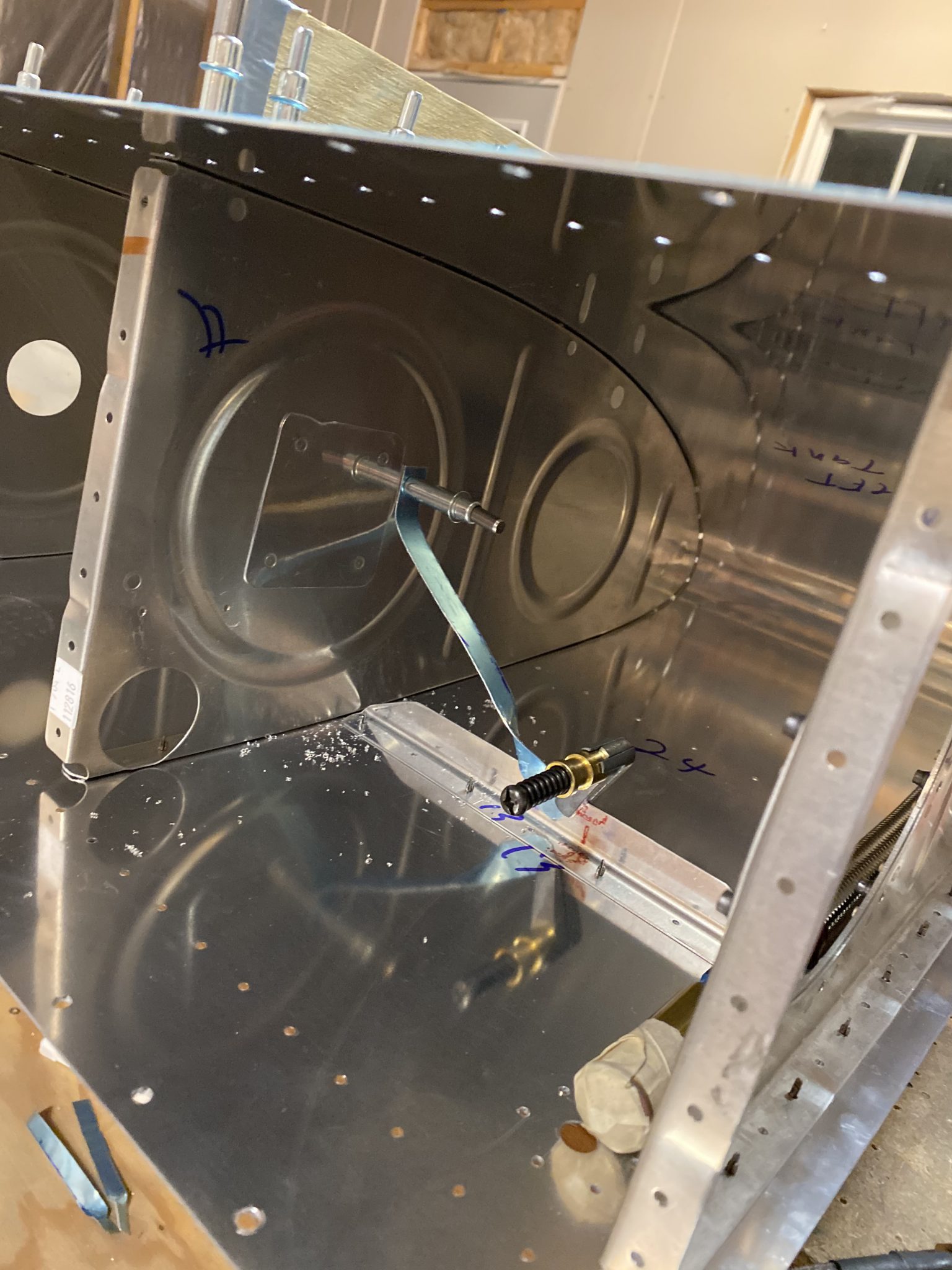
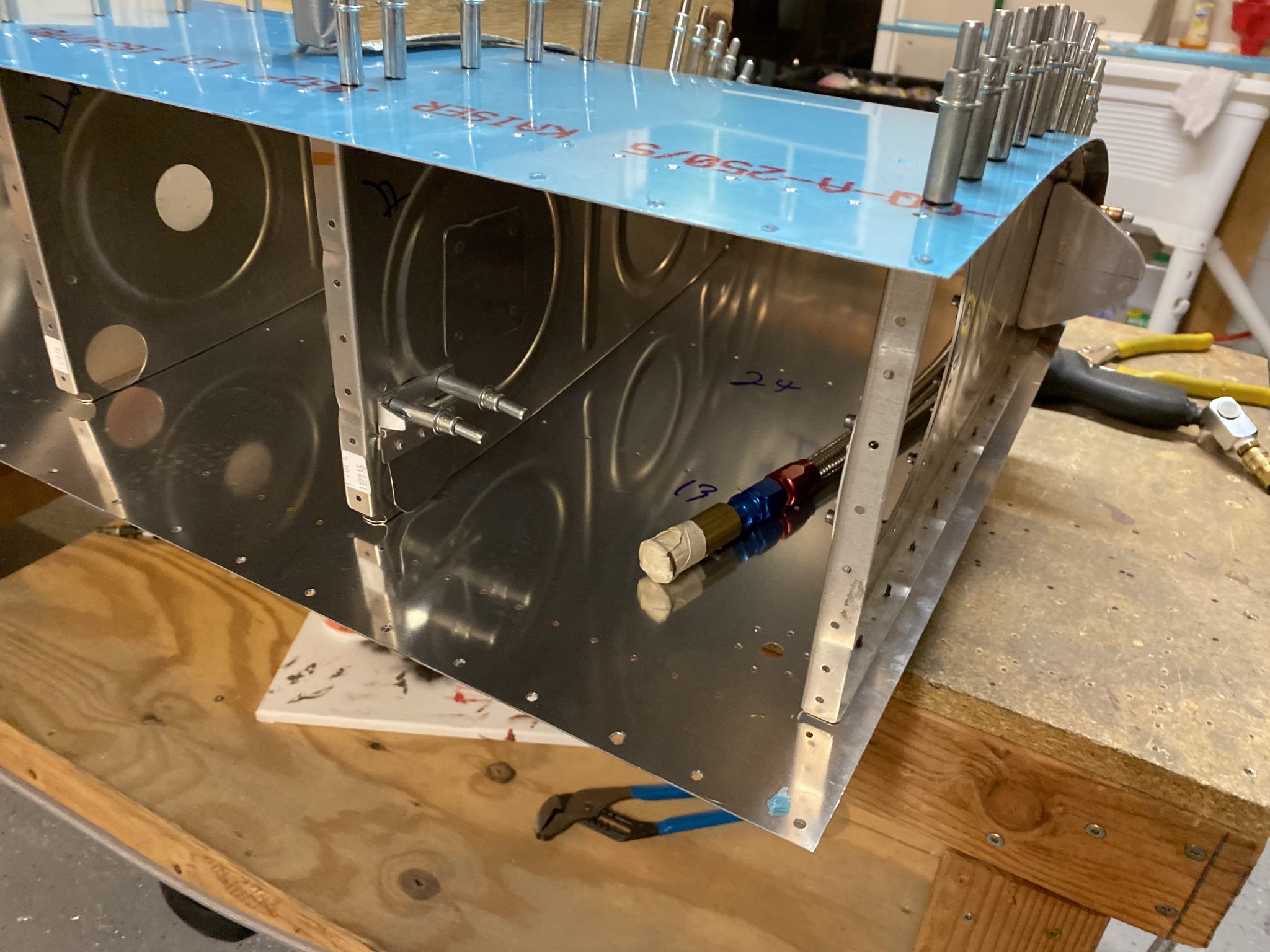
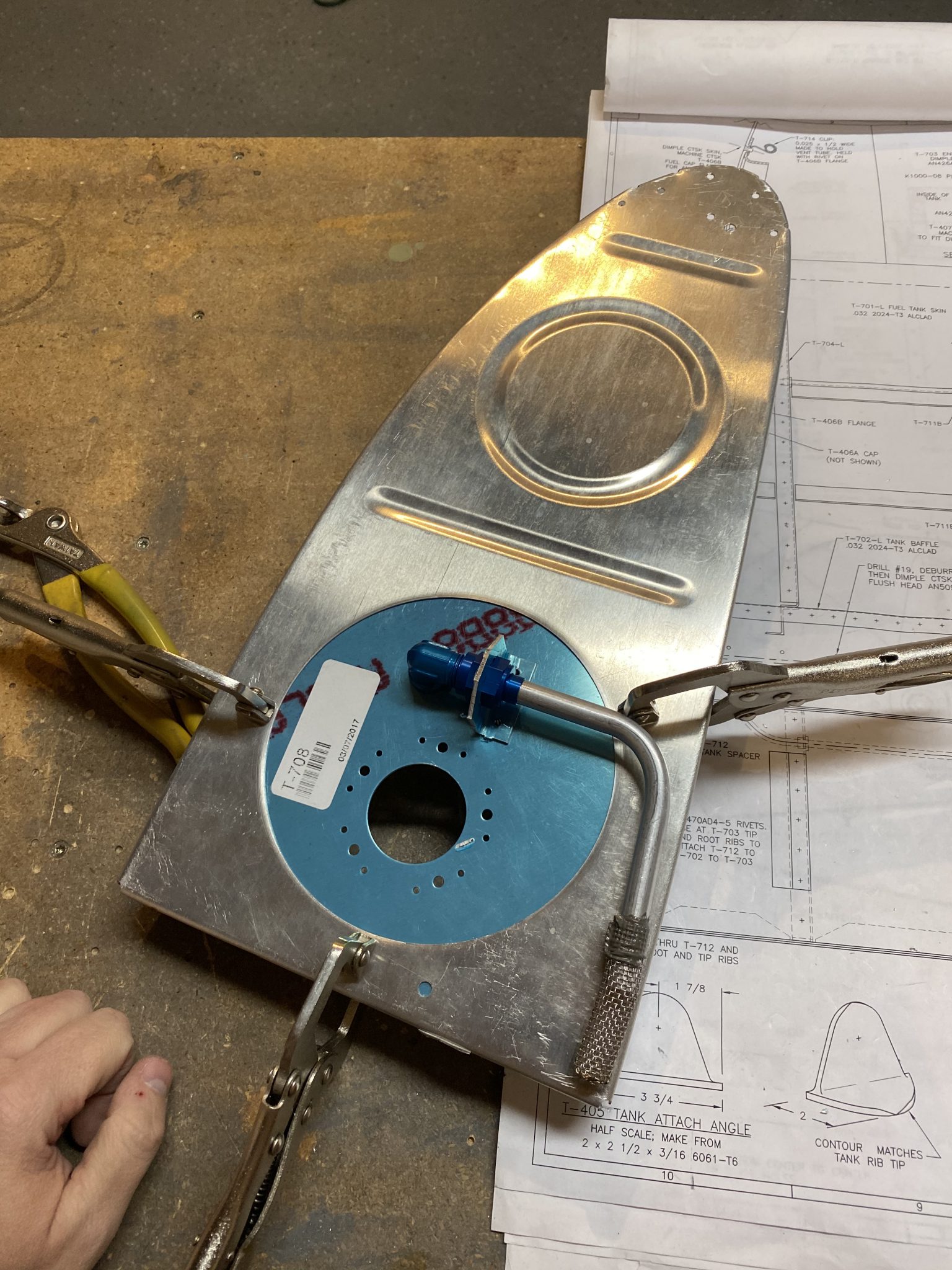
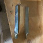
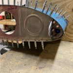
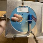
I put some masking tape on my flop tube to keep trash and debris out of it, and also to protect the little rubber o-ring bumper during the assembly process. I wasn’t very happy with the way the anti-rotation brackets from Vans worked out, as I didn’t have enough room to fit one of them. The plans don’t call for an anti-rotation bracket on the flop tube, but does have us safety wire that fitting. That safety wire will only keep the fitting from rotating, it wont stop the actual bulkhead from rotating as the flop tube…flops. So, I decided to fabricate my own bracket. They are simple enough to make, and I had plenty of stock angle to work from. This actually took me longer than I had thought it would to make, and I went through several iterations before I had one I was happy with. Thank goodness I had plenty of angle stock to work with!
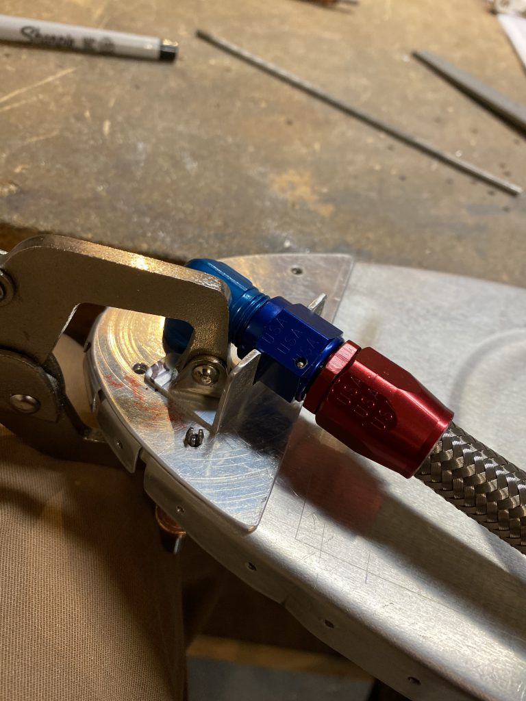
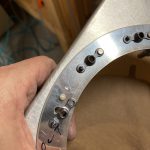
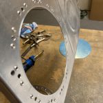
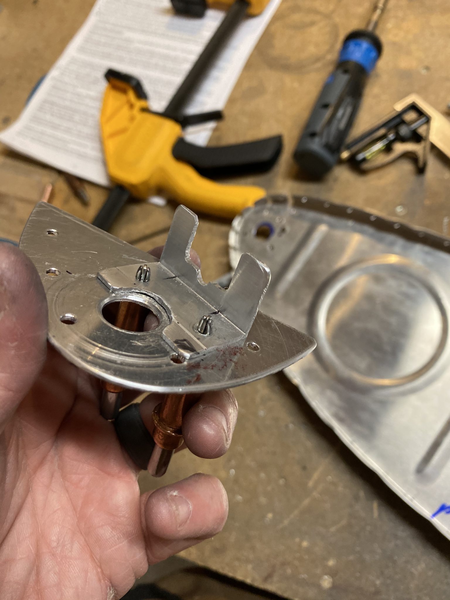
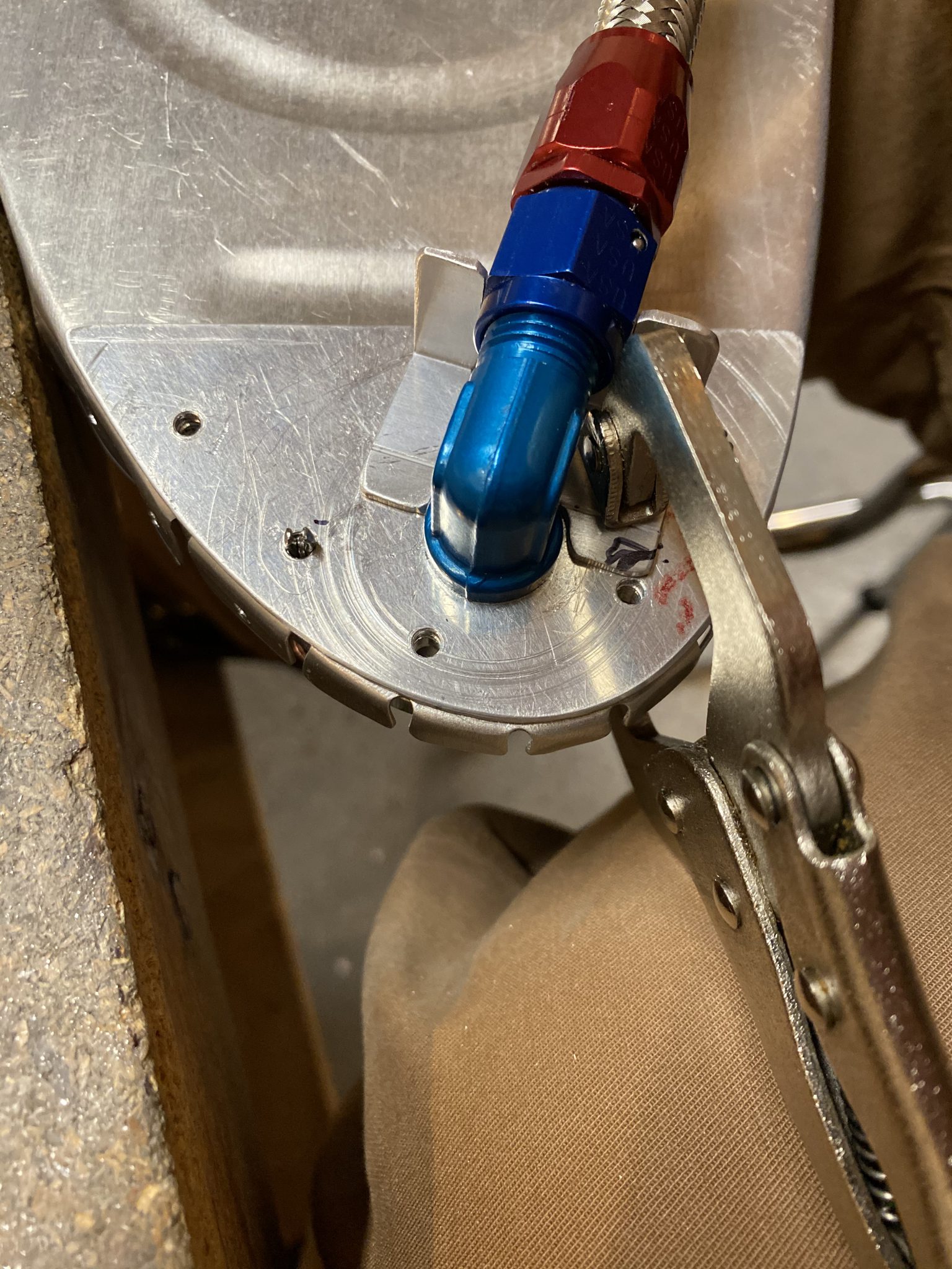
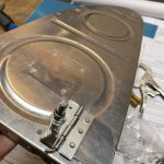
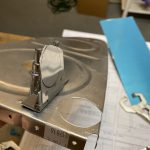
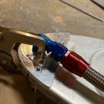
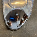
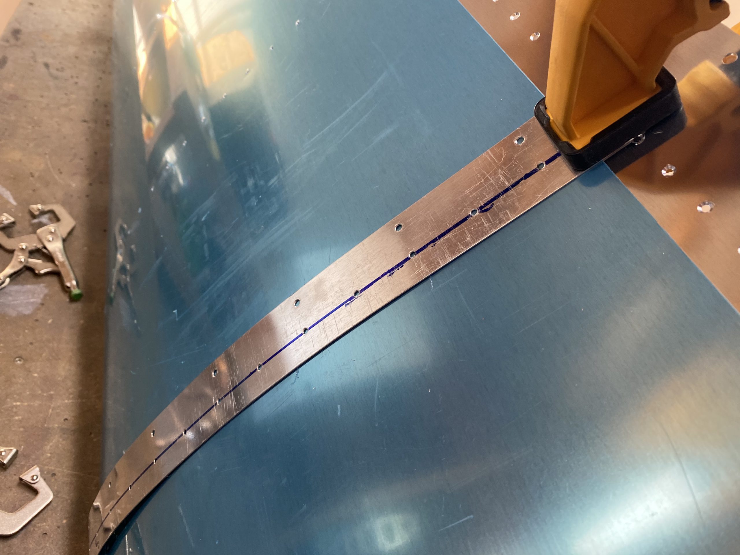
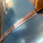
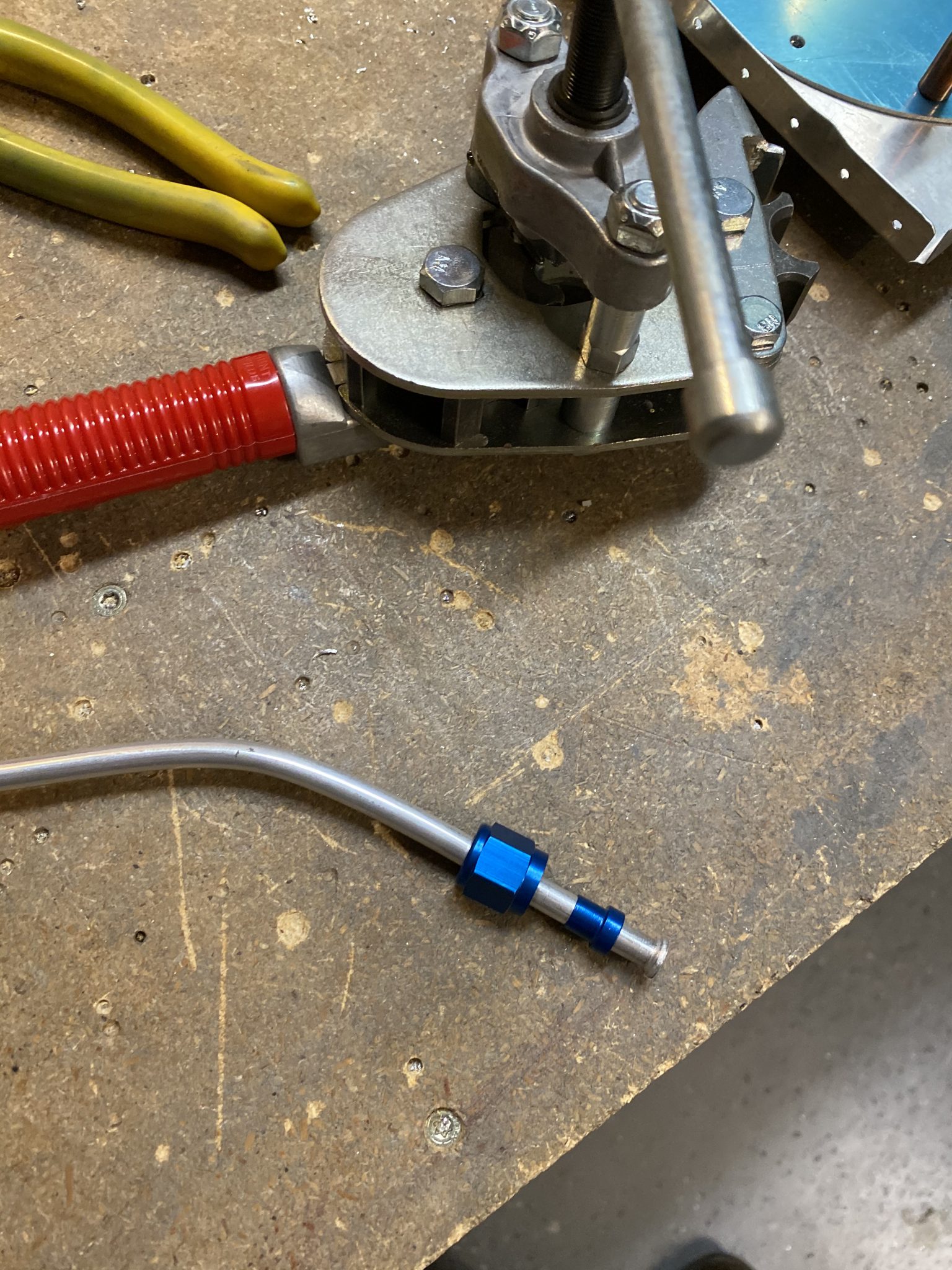
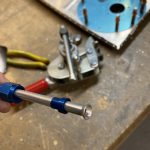
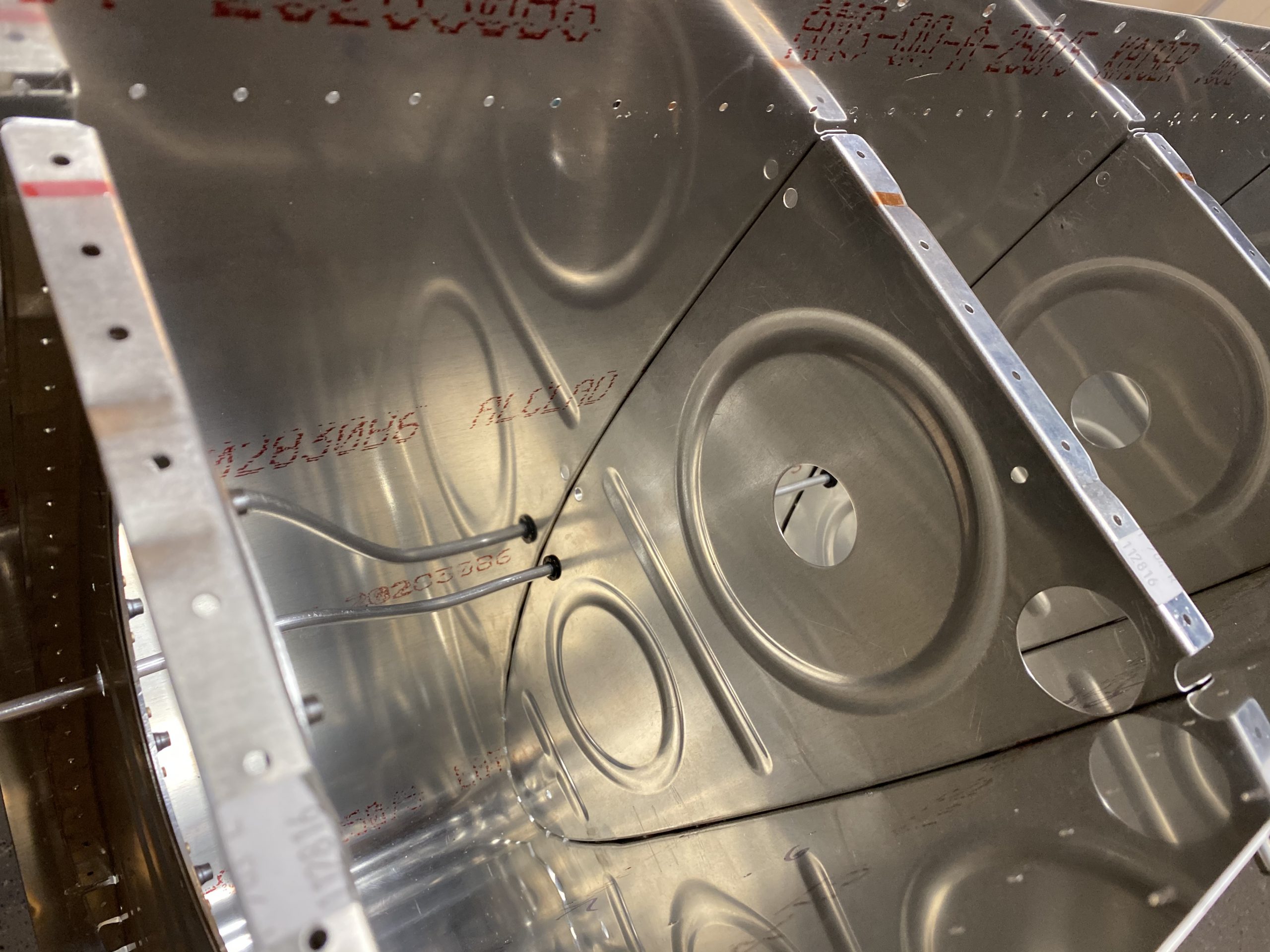
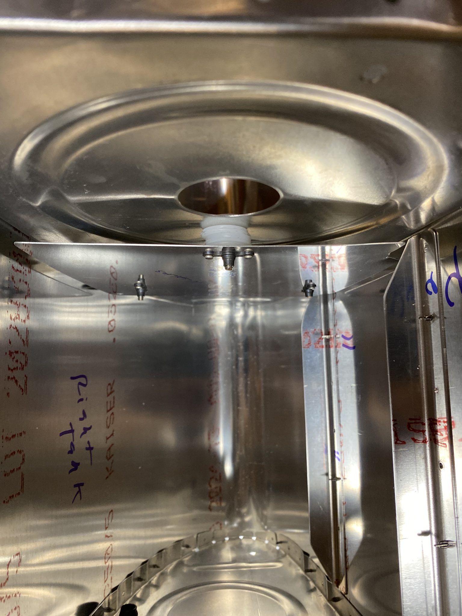
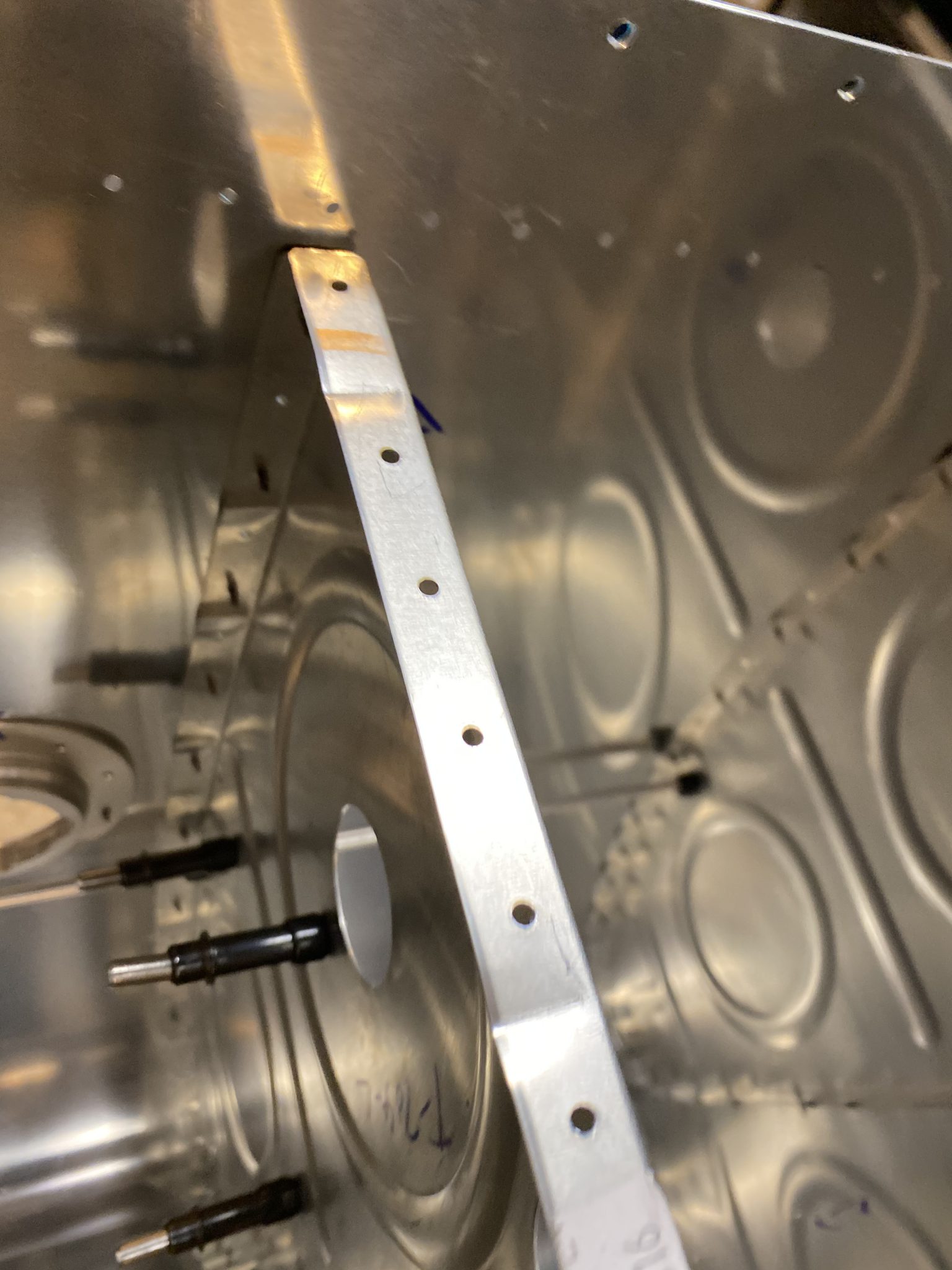
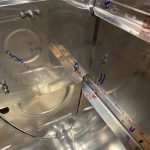
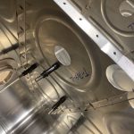
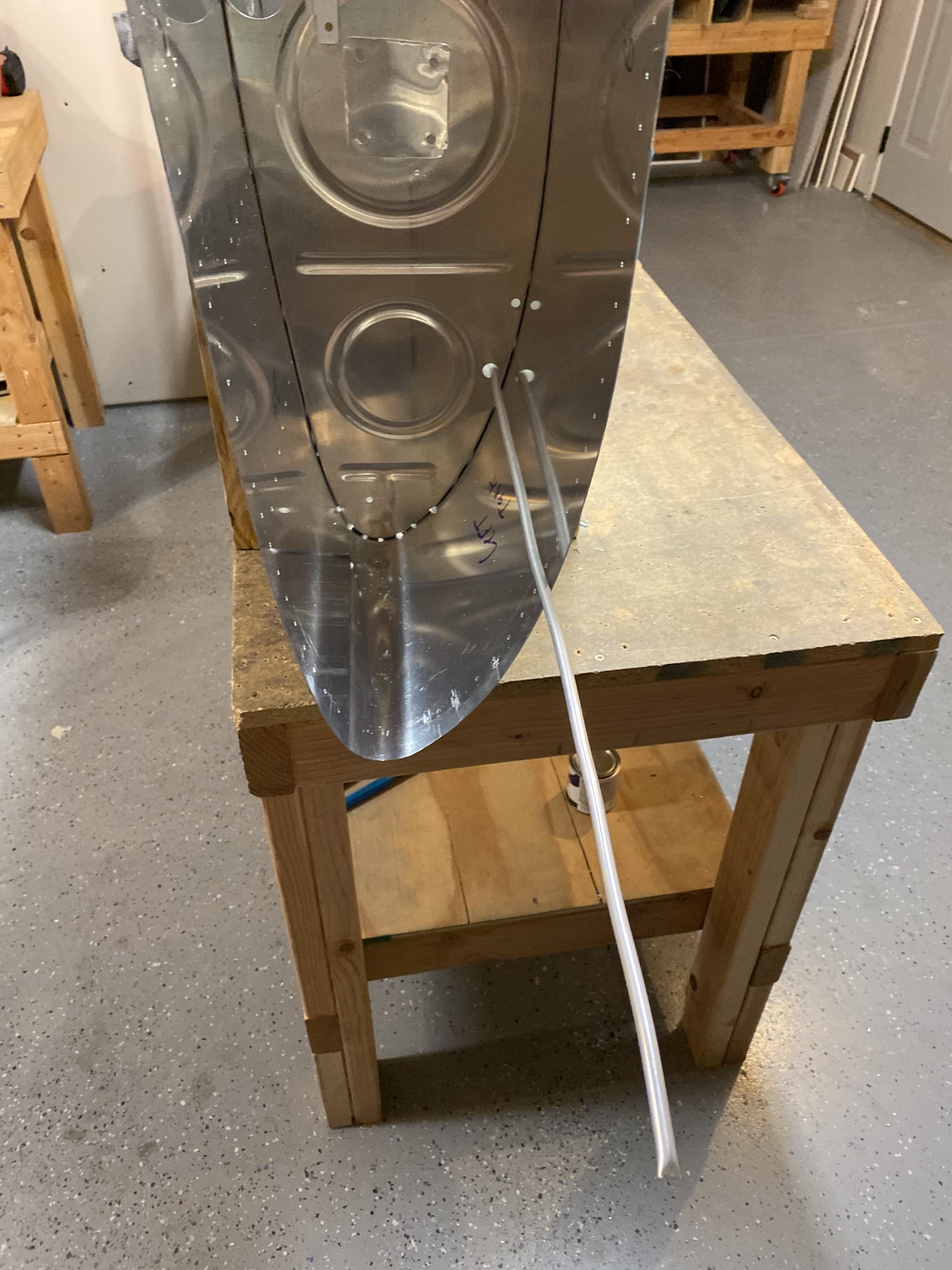
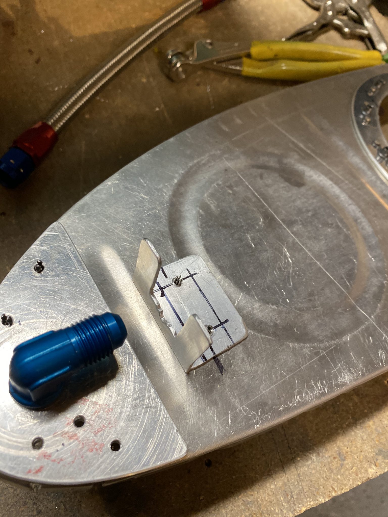
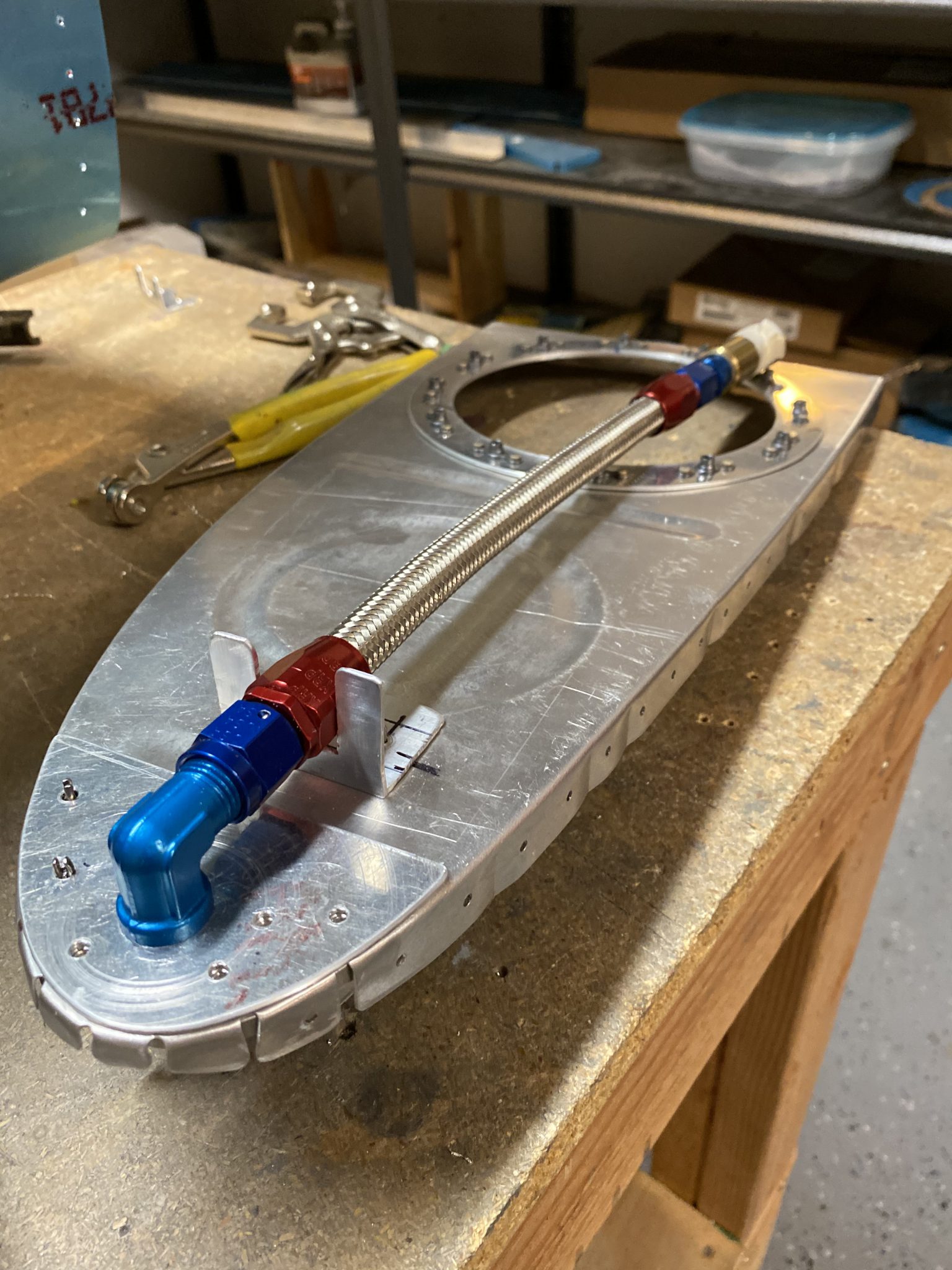
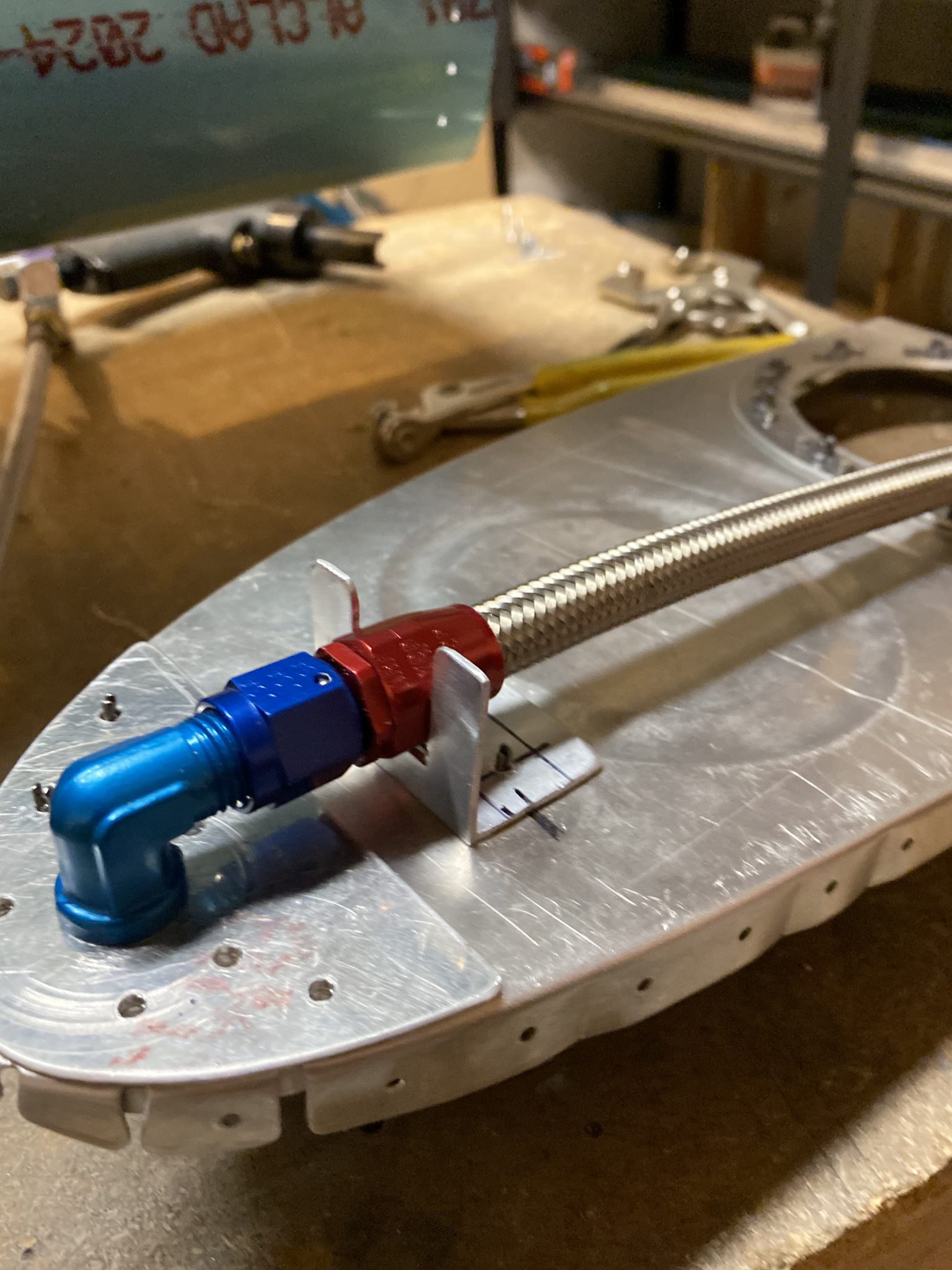
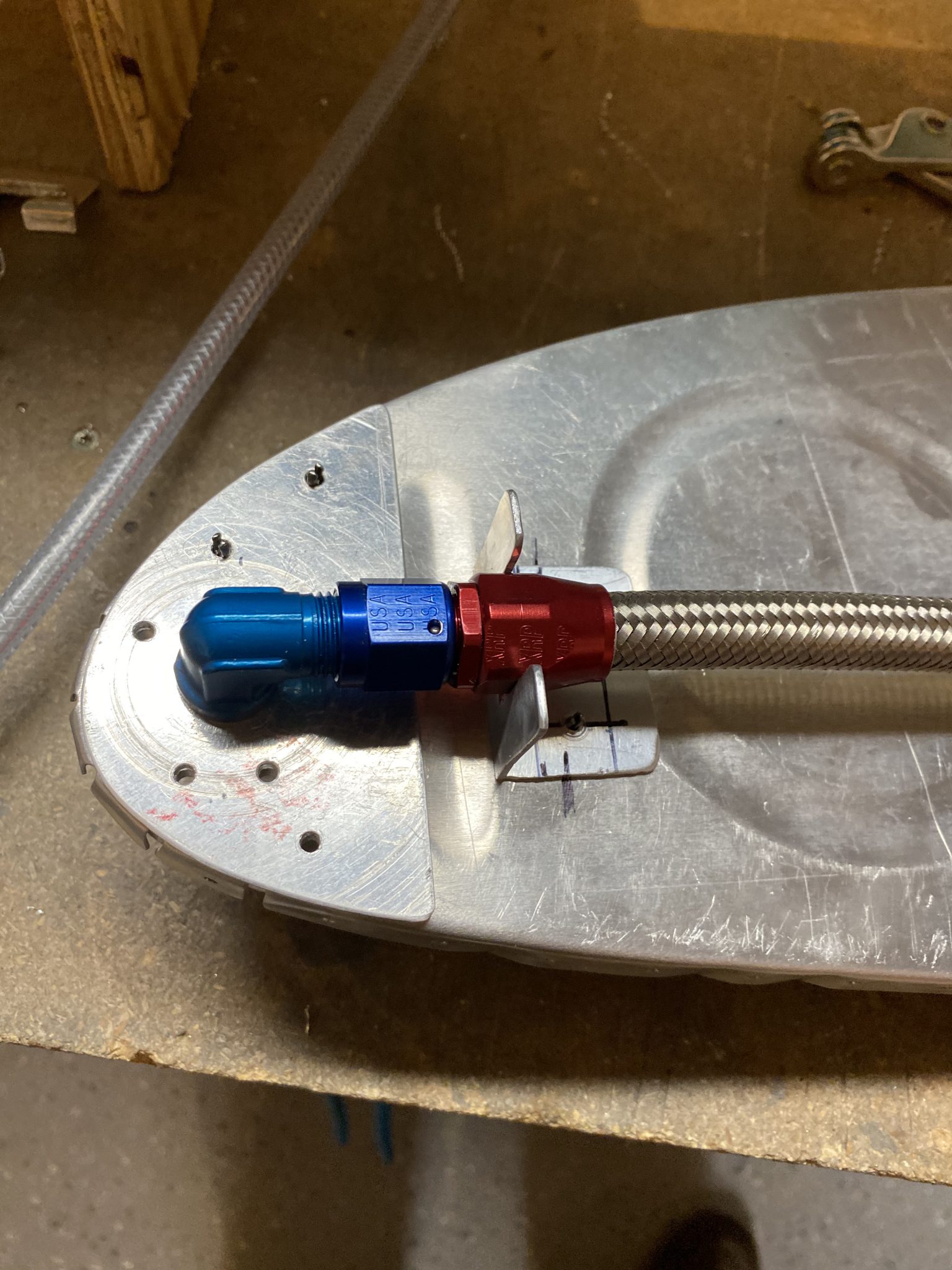
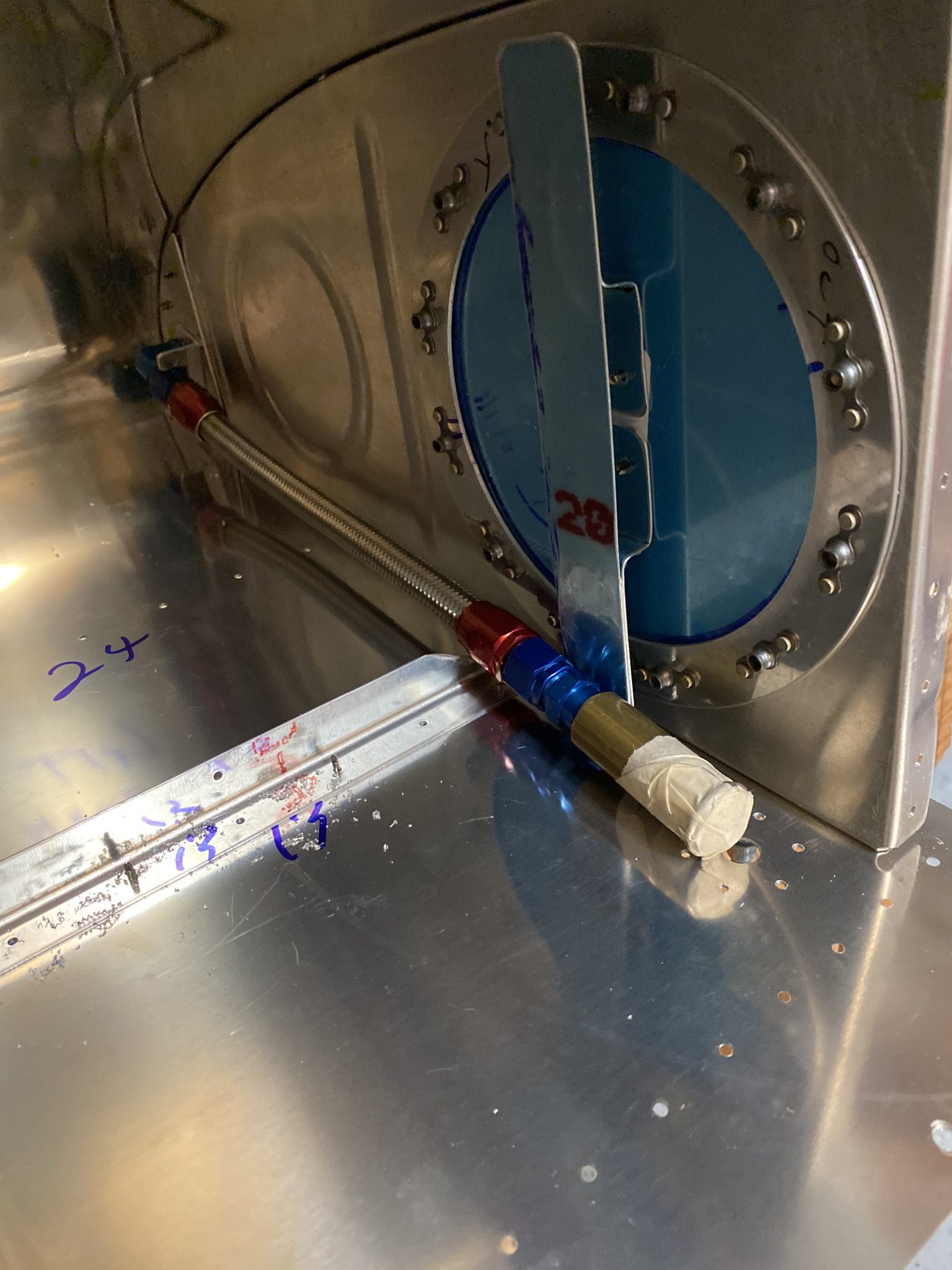
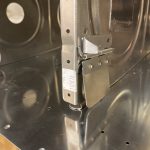
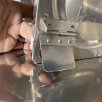
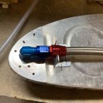
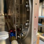
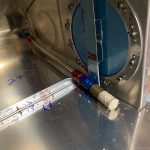
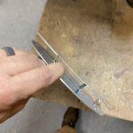
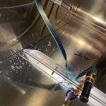
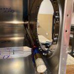
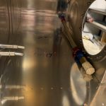
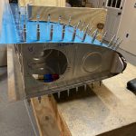
I angled my flop tube and its associated anti-rotation bracket slightly downward so that the fuel pickup would rest as low as possible in the fuel tanks. It will still flop around perfectly fine and pick up fuel in the inverted and knife-edge flight attitudes. Here is the anti-rotation bracket clamped down and getting drilled into place.
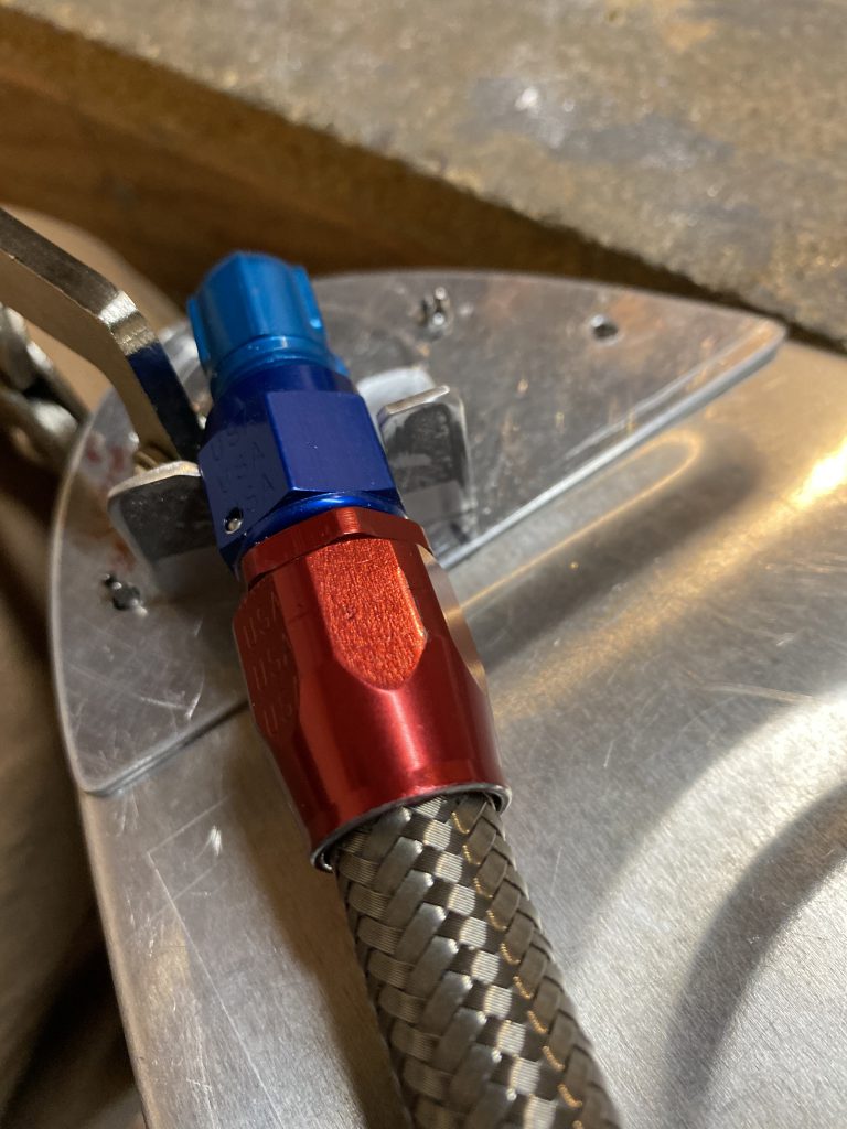
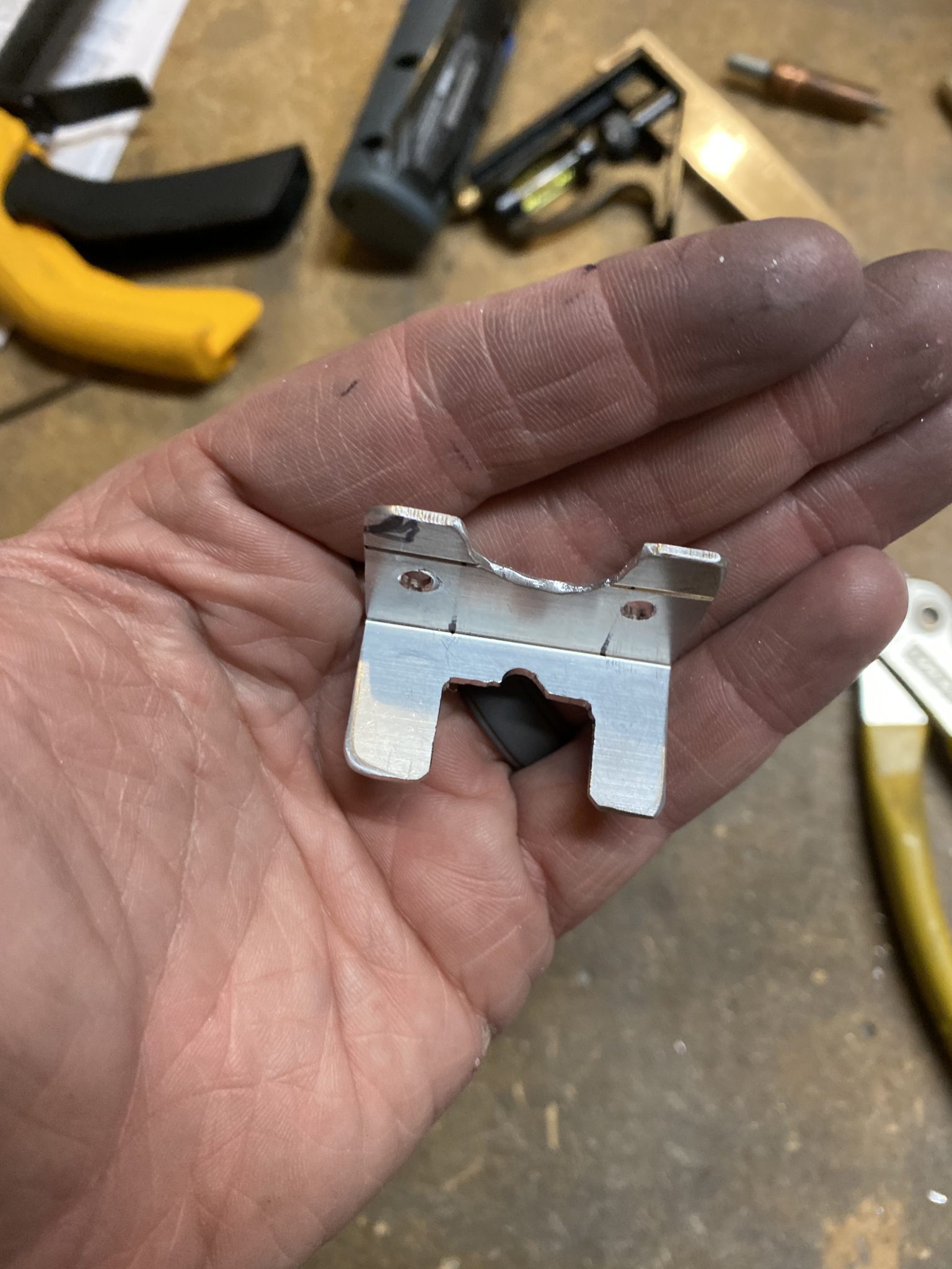
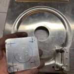
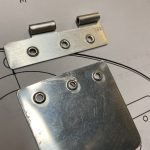
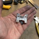
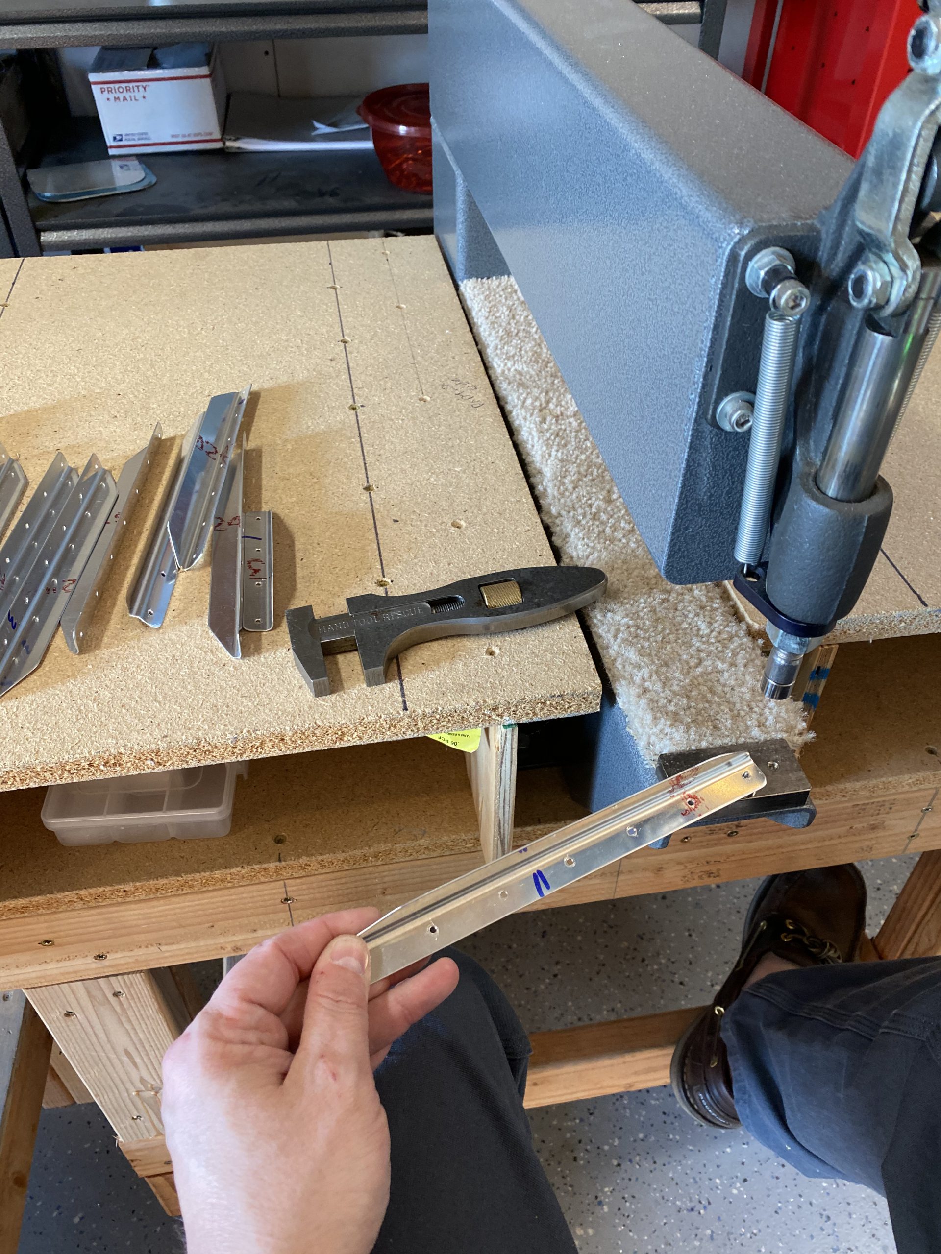
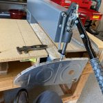
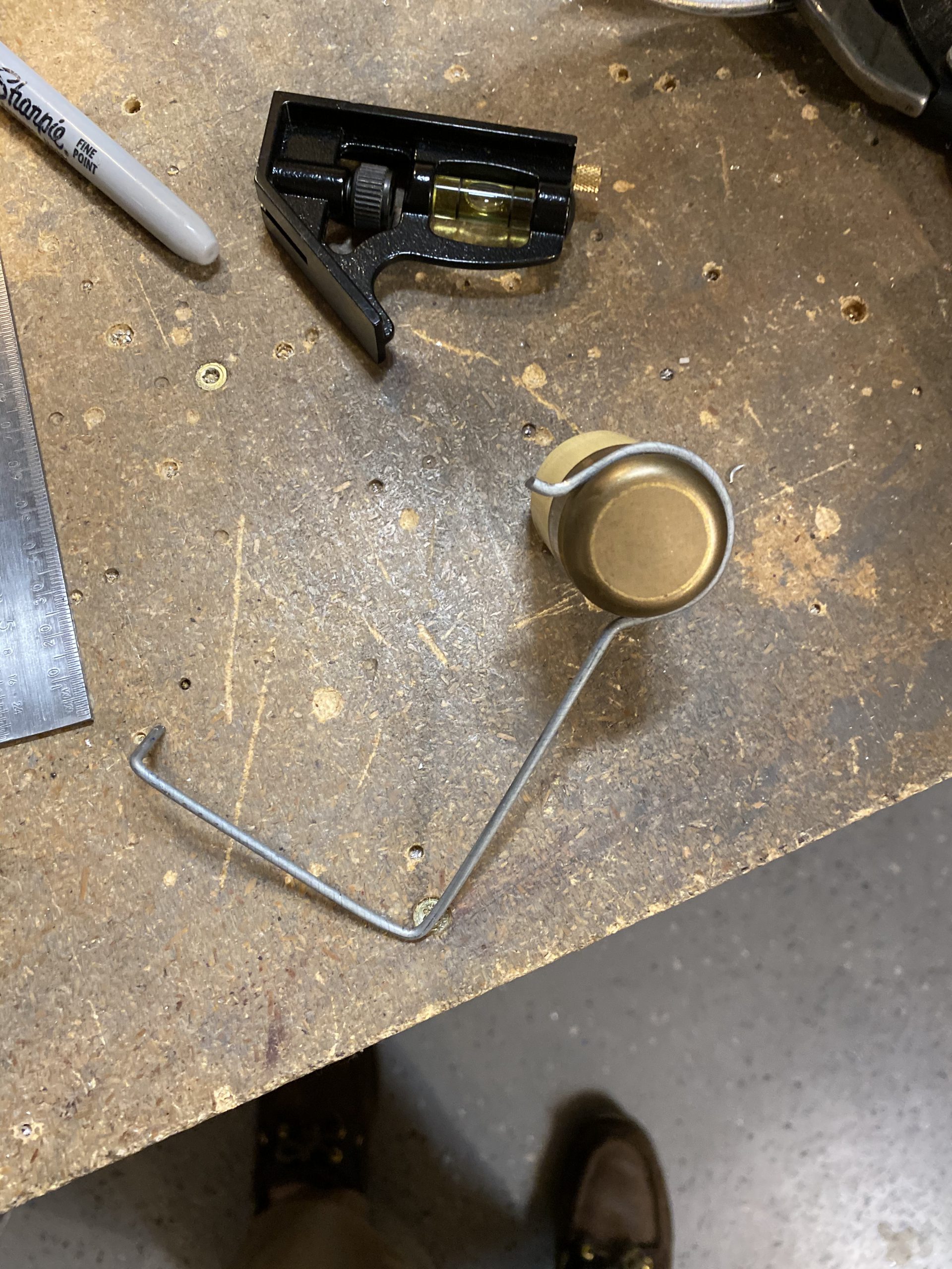
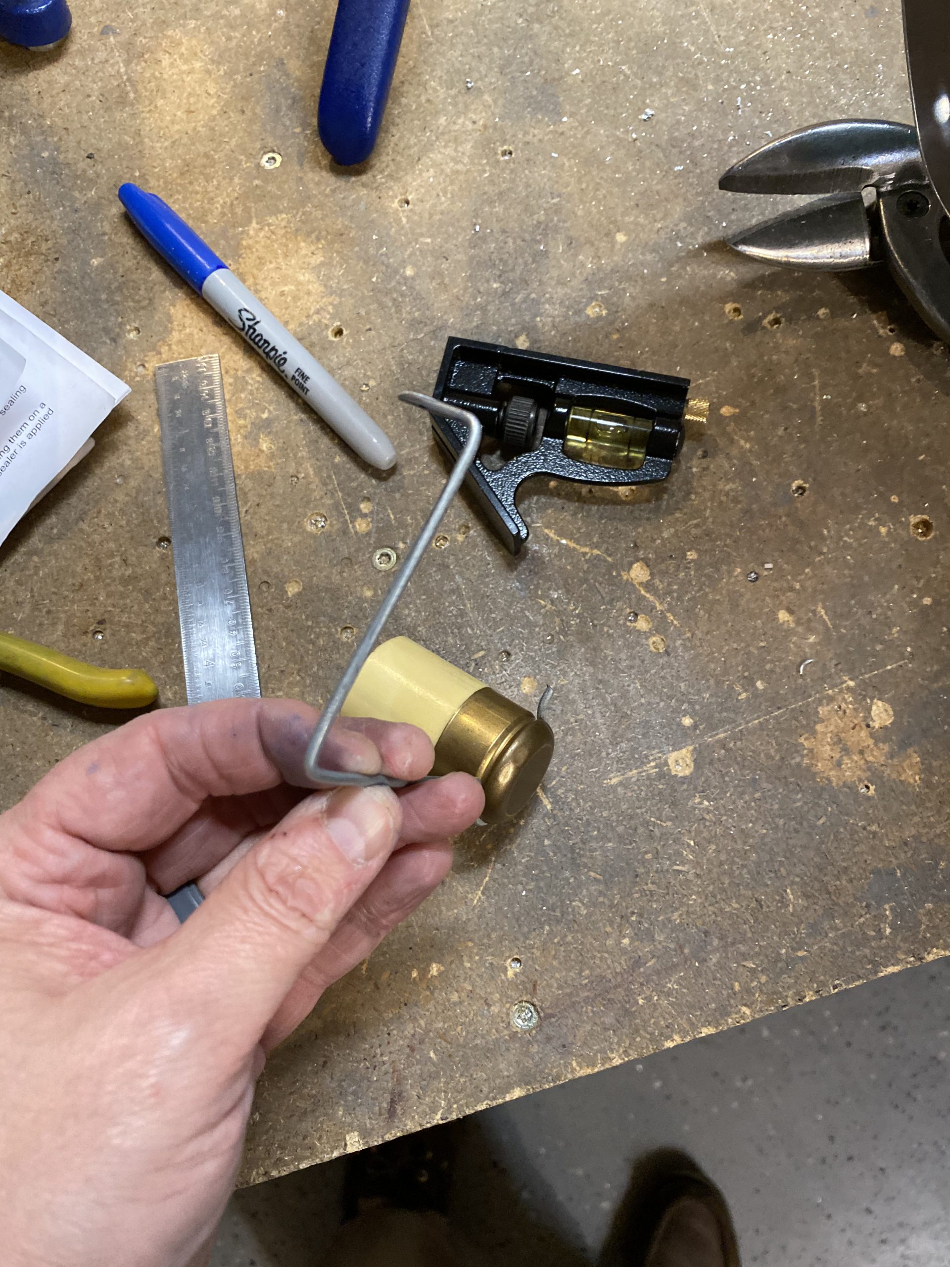
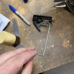
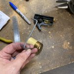
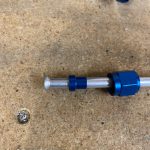
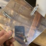
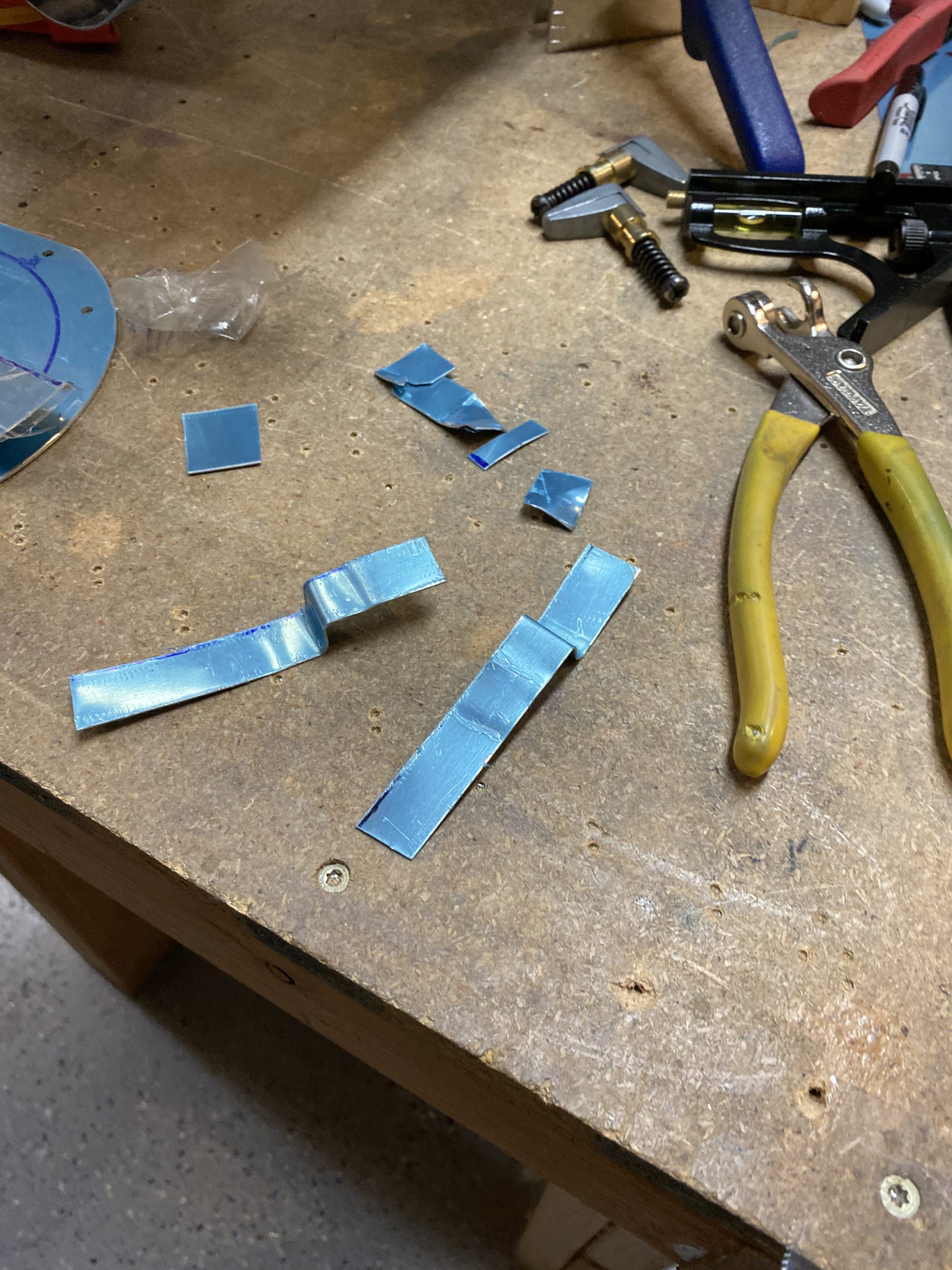
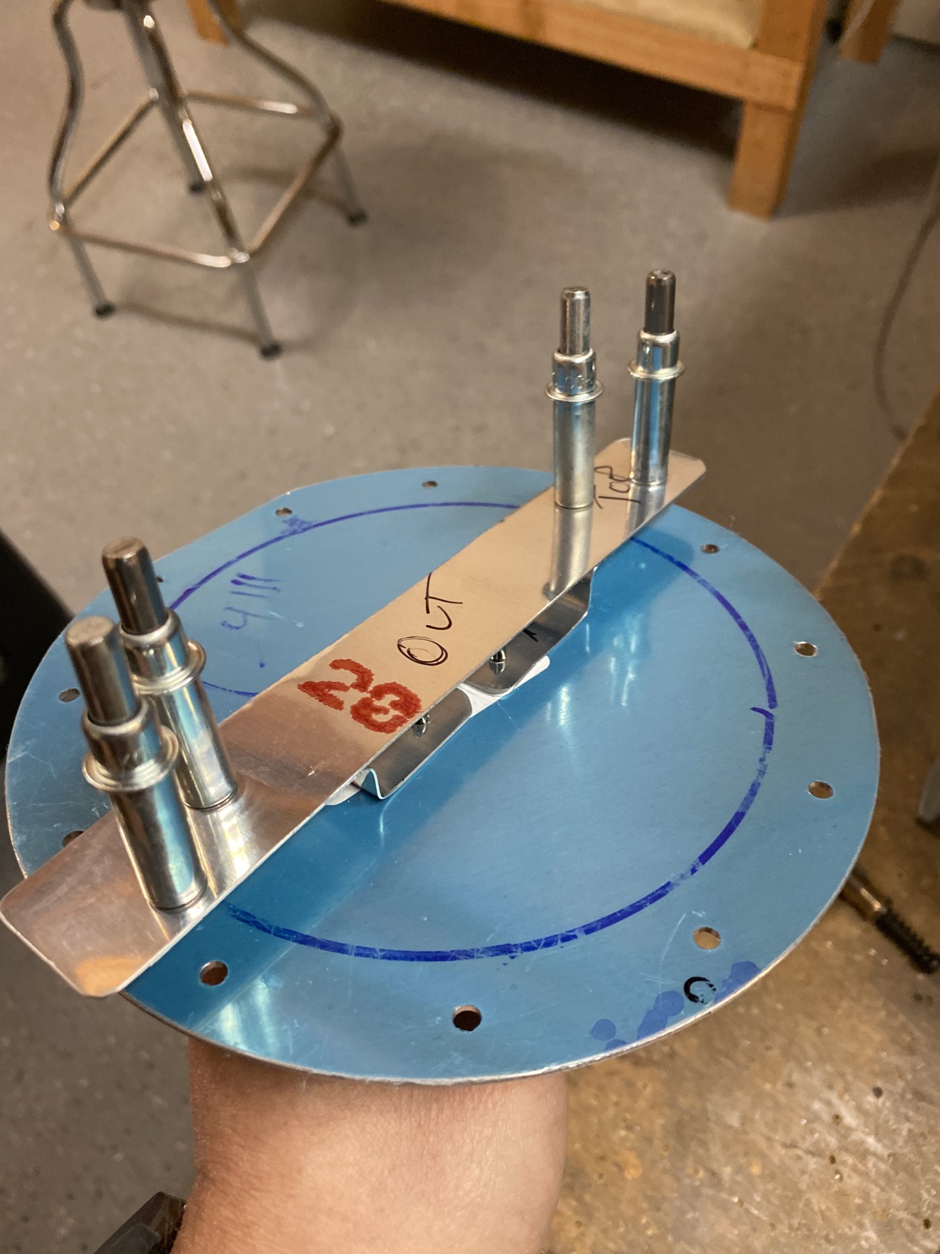
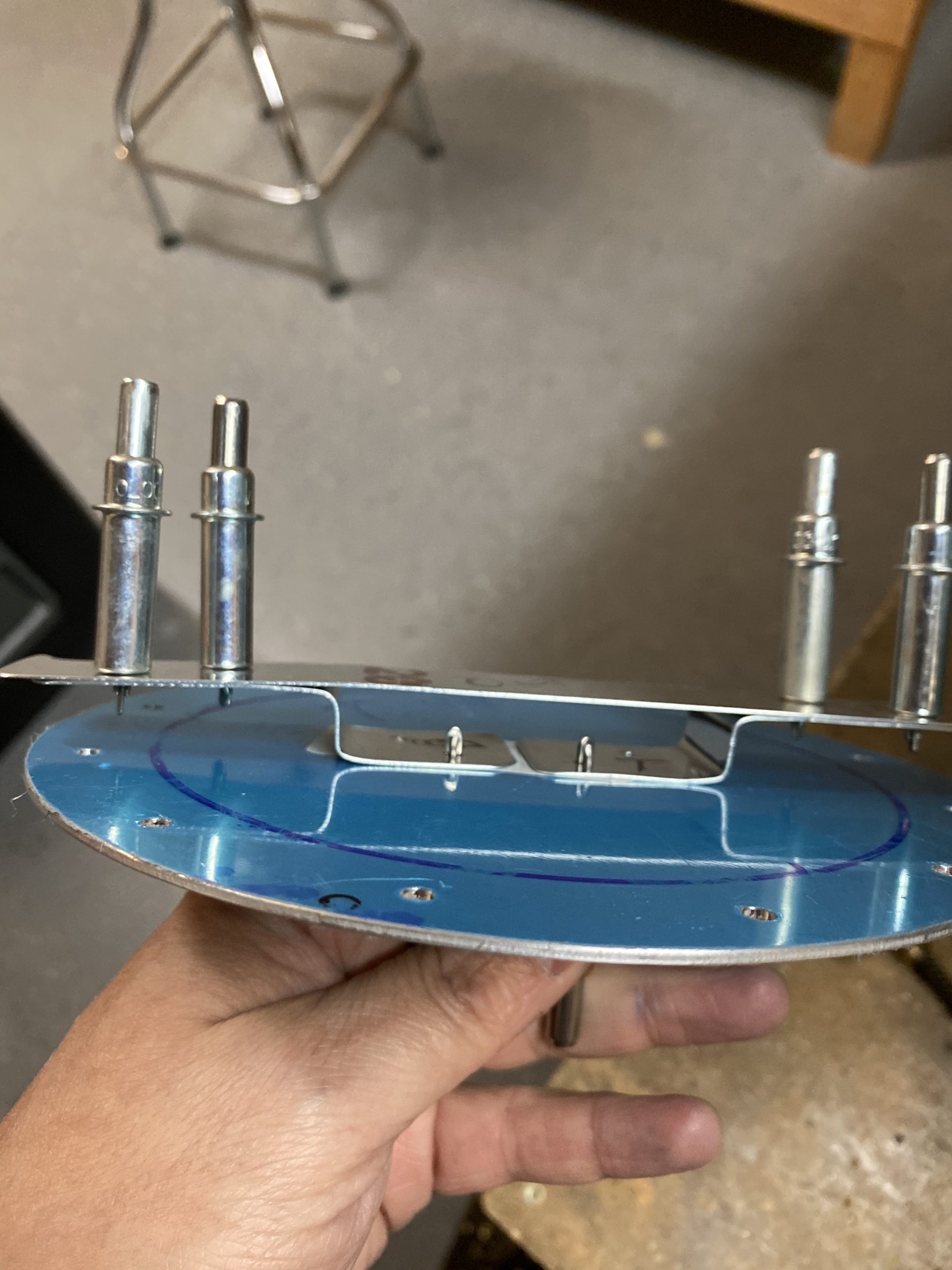
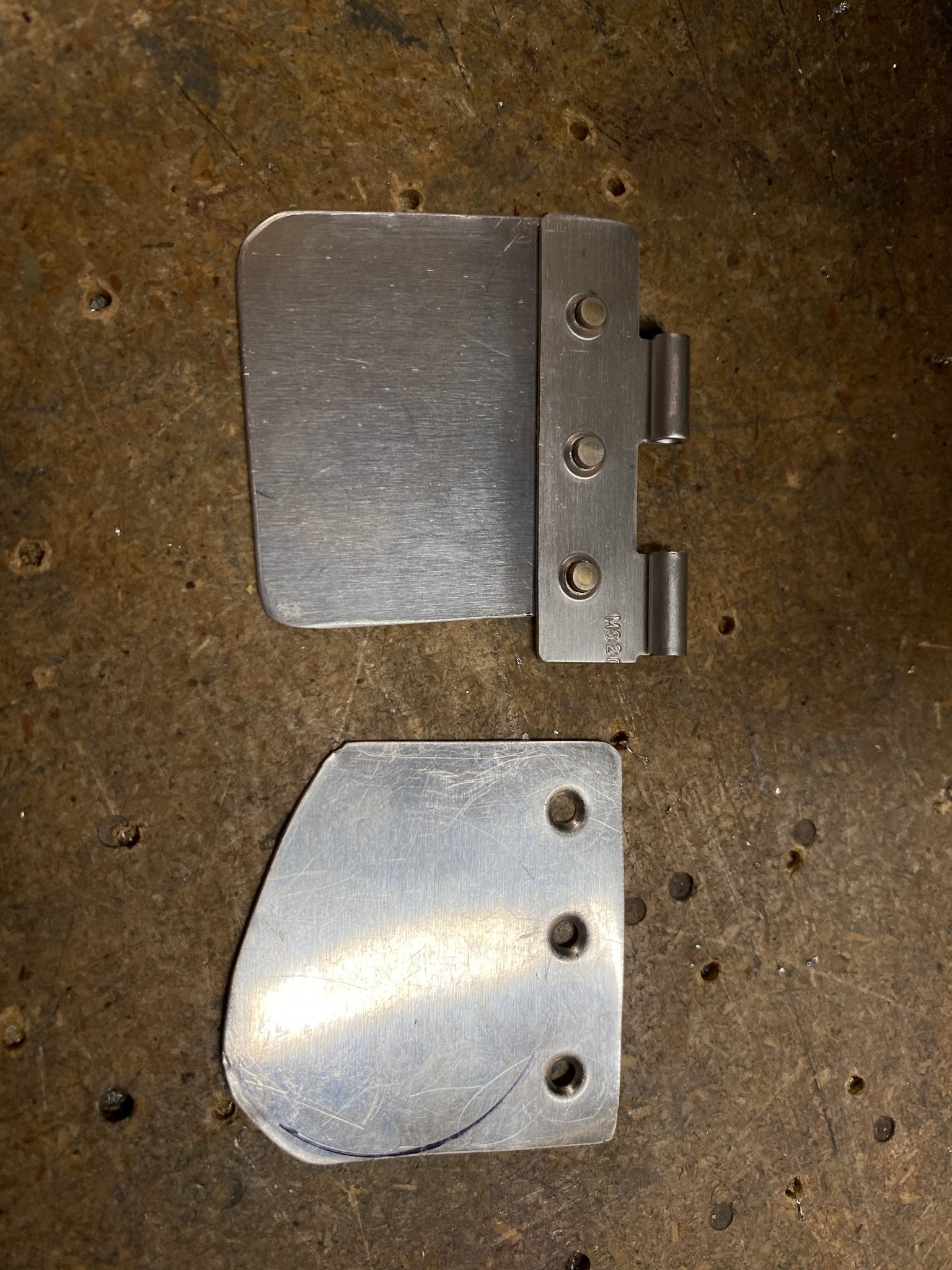
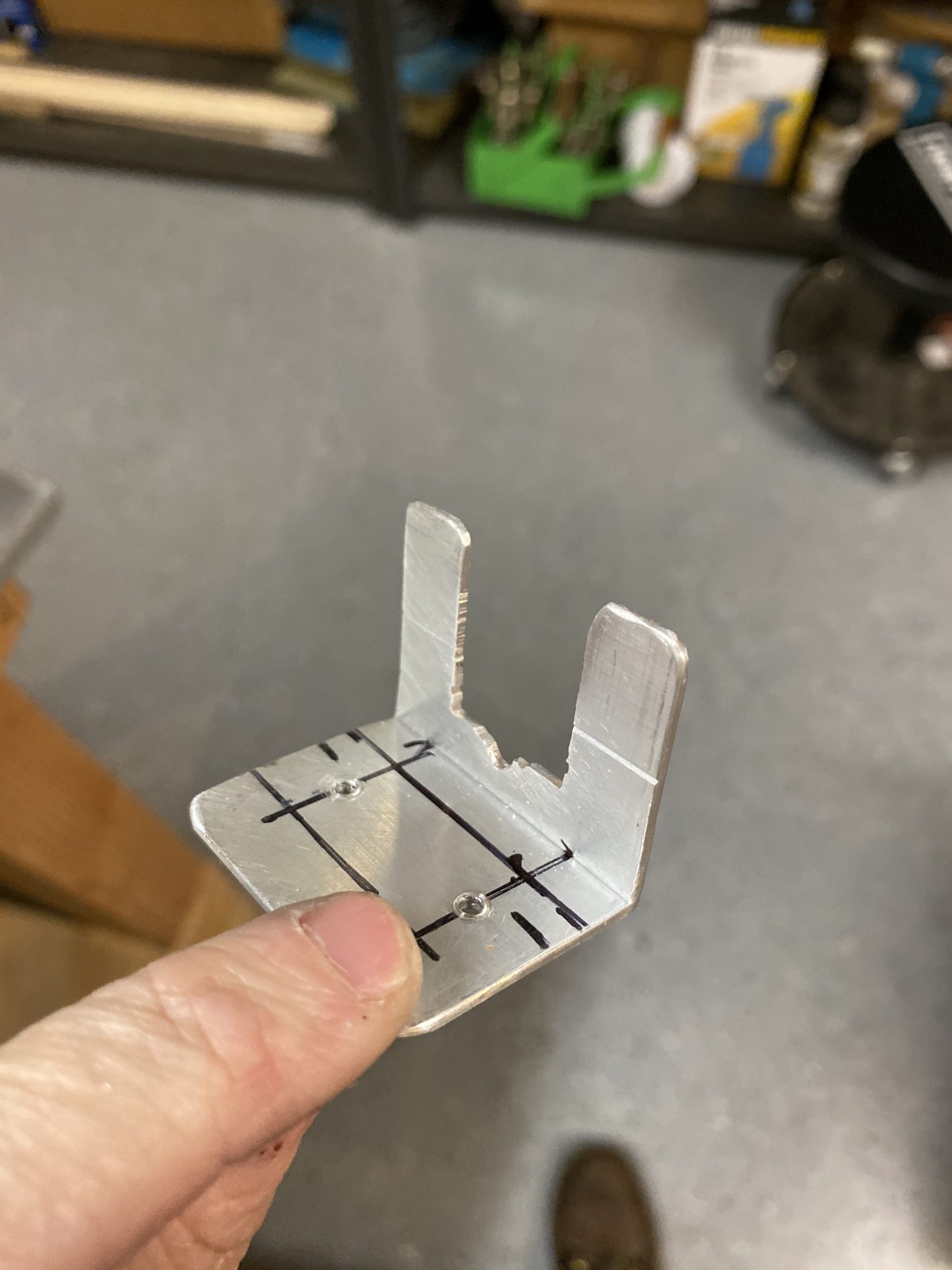
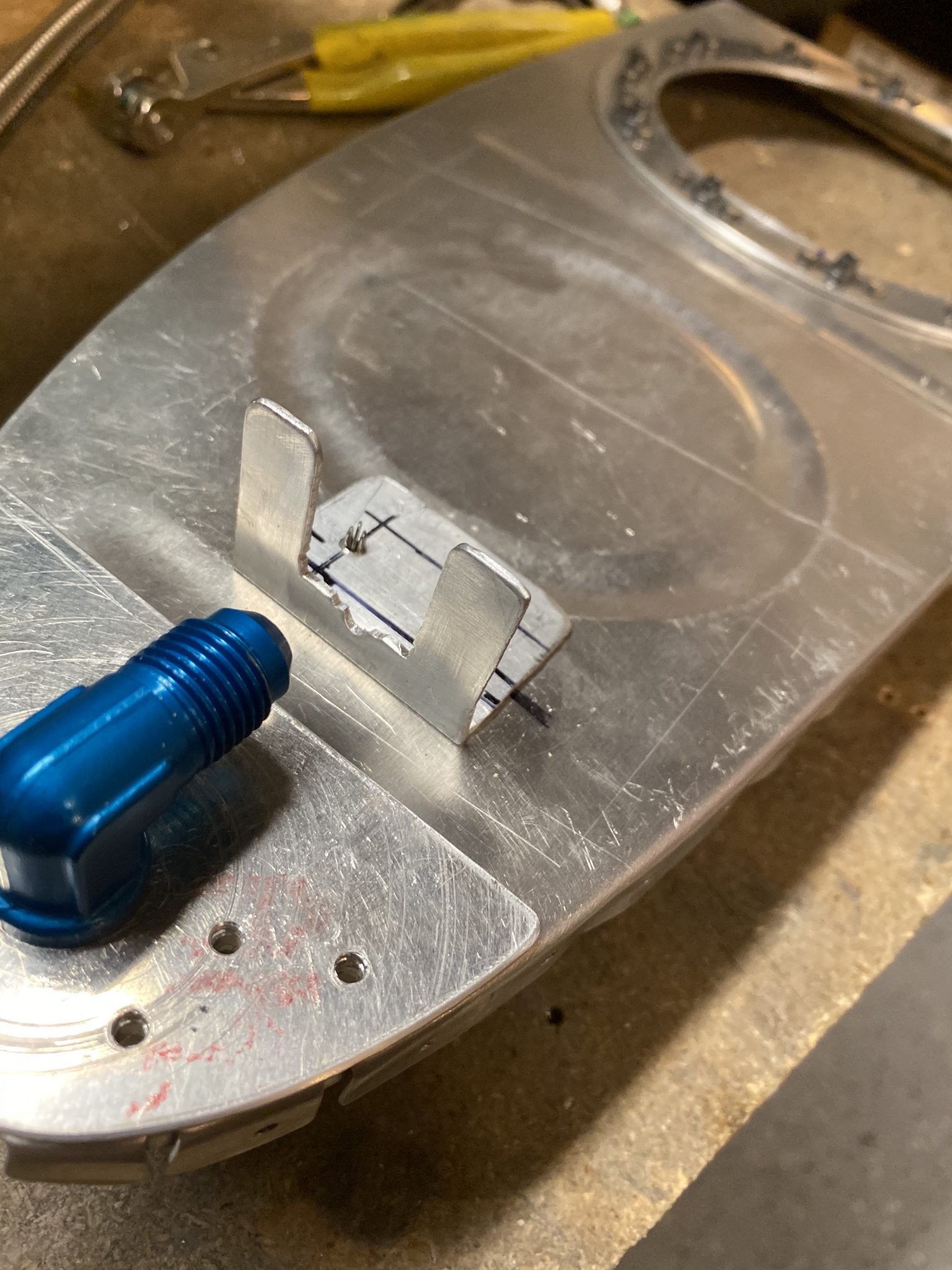
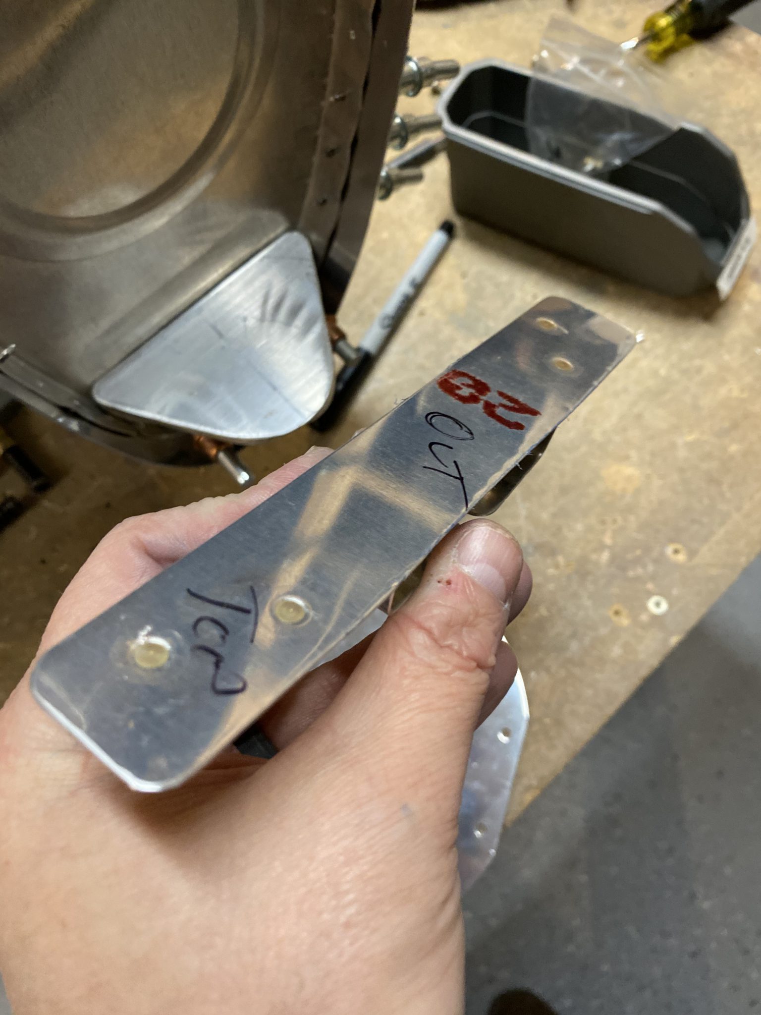
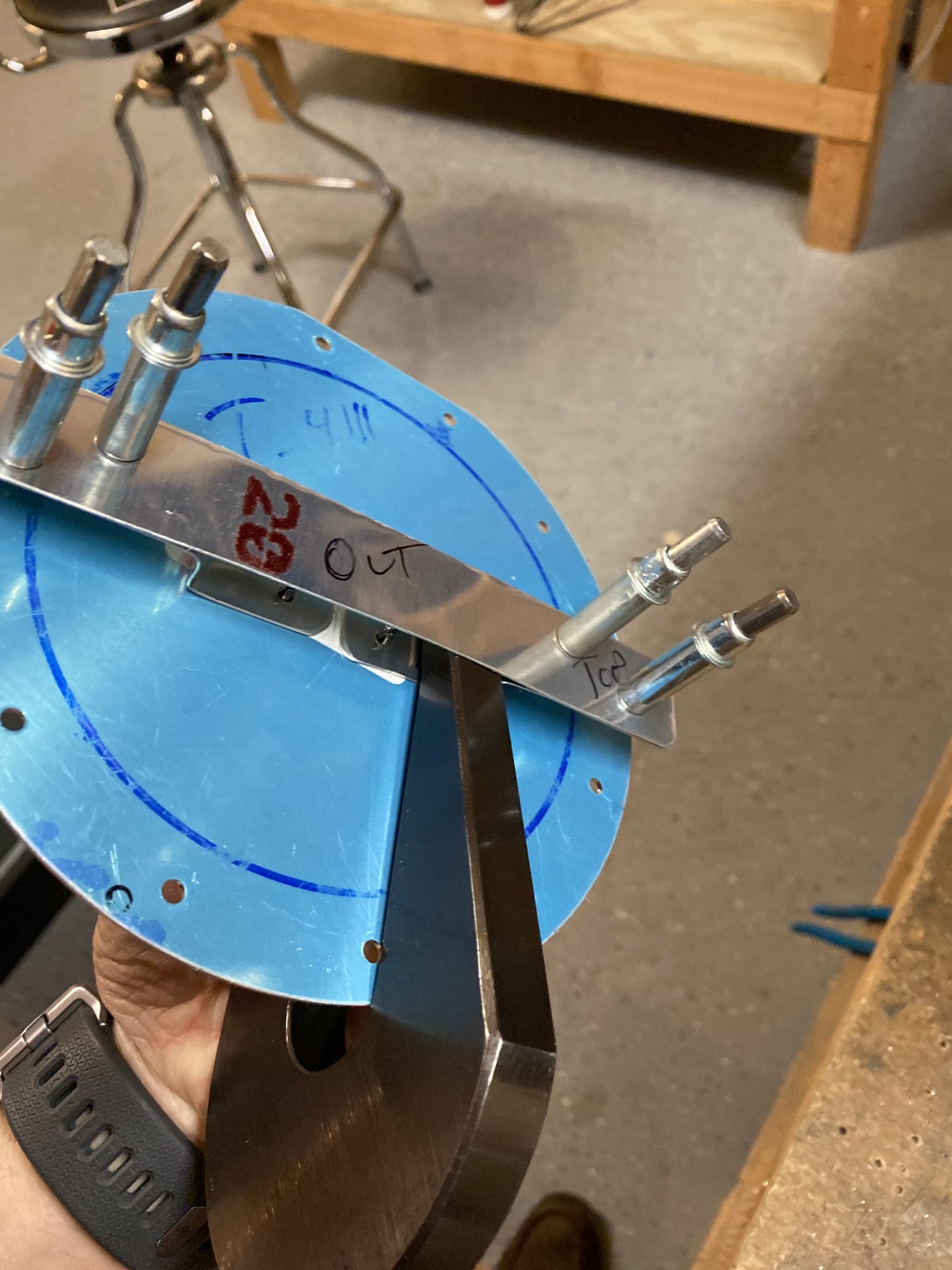
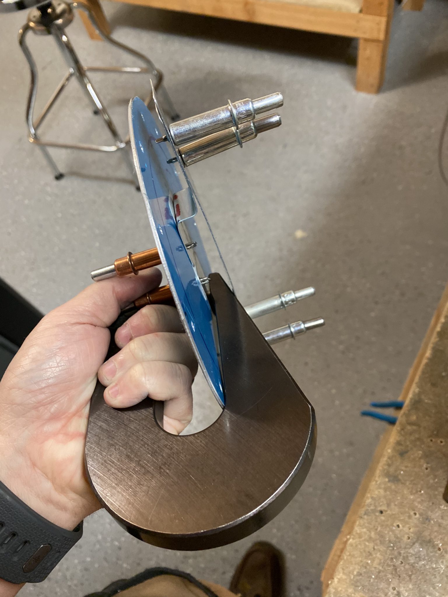
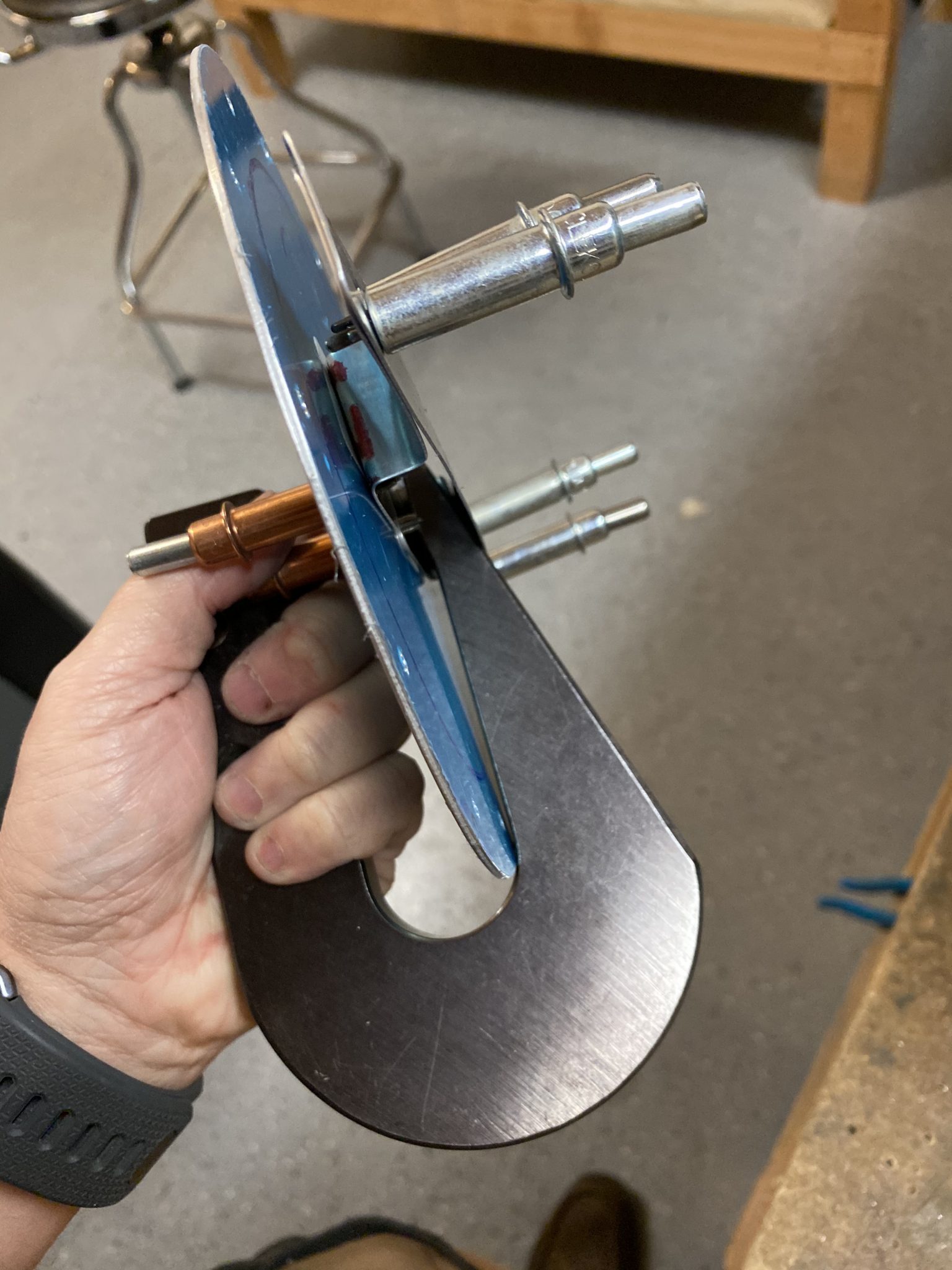
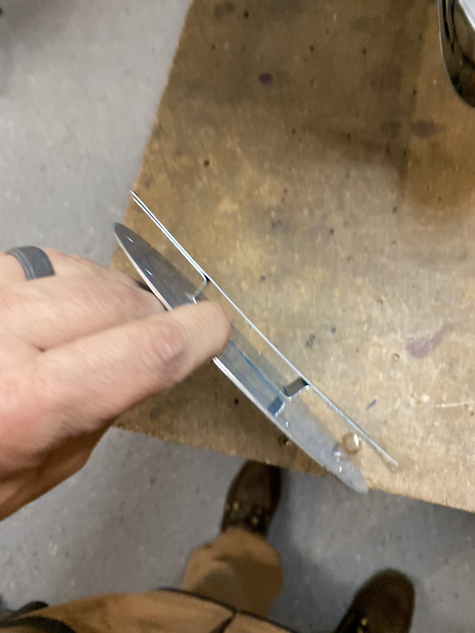
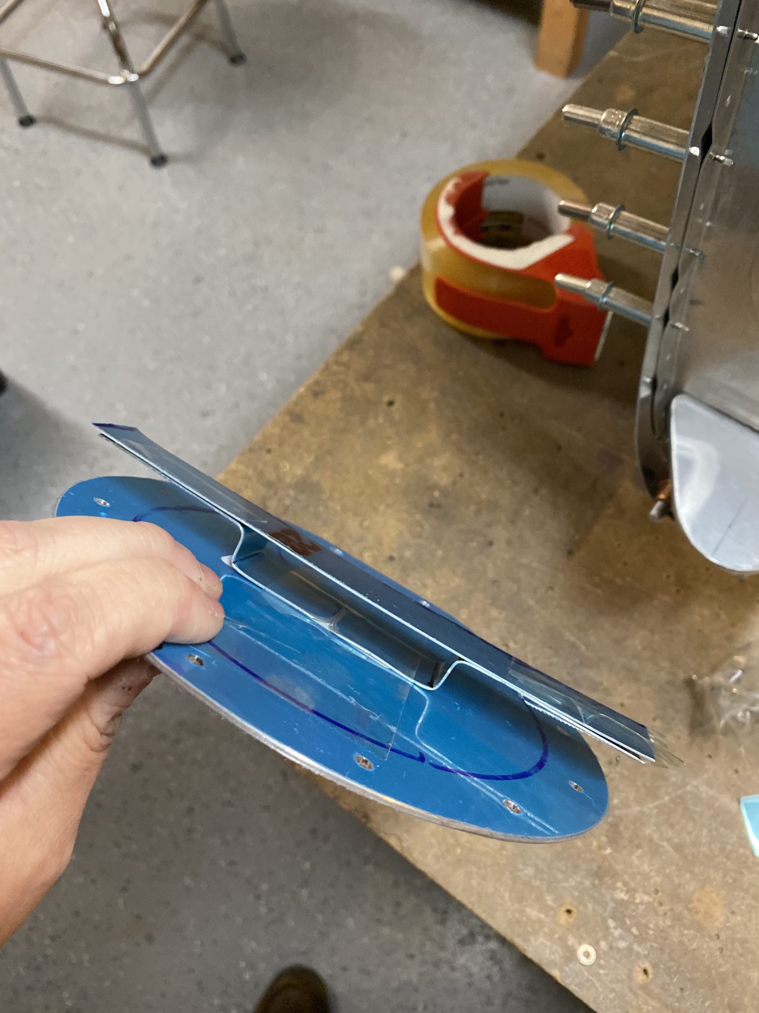
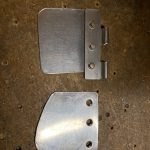
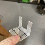
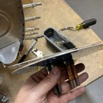
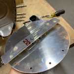
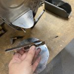
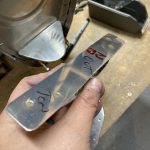
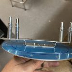
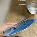
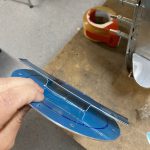
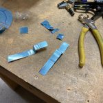
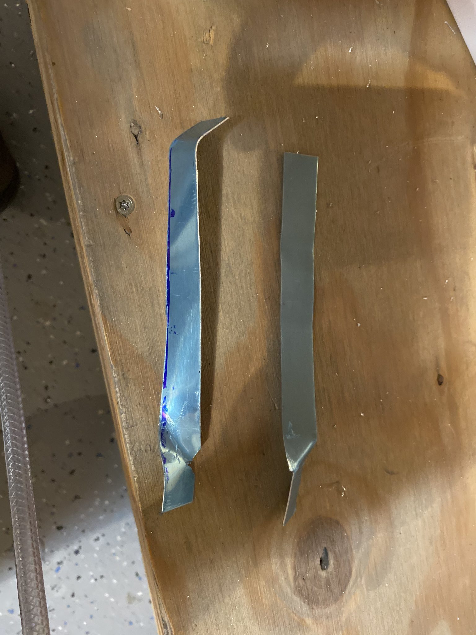
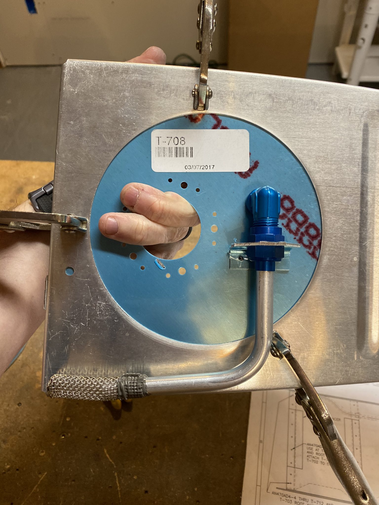
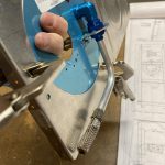
And below is what I eventually ended up with. The rounded section goes against the rounded shoulder of the bulkhead fitting with a few 16ths clearance, while the squared end is roughly 11/16″ which is just slightly bigger than the flats on the fitting. This way, when I tighten the flop tube up on its fittings, I can rotate the flats to line up with the bracket, which will serve double duty: Keeping the flop tube from rotating around the where the bulkhead goes, as well as keeping the fitting from rotating counterclockwise and loosening itself off the threads. I actually notched the bottom of the bracket so that the points of the fitting would sit nicely down in it, giving me good clearance. I am actually pretty proud of this little bracket! It’s really simple, but took quite a bit of learning and work to create. I will be much better at making them if I ever decide to build another RV 🙂
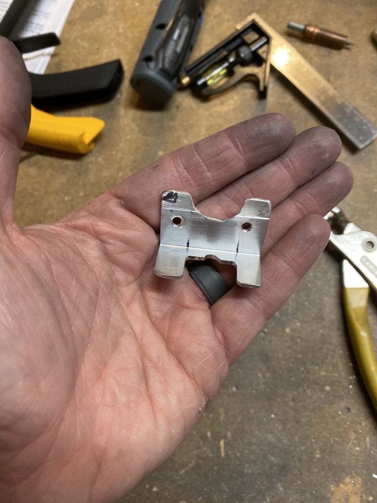
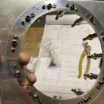
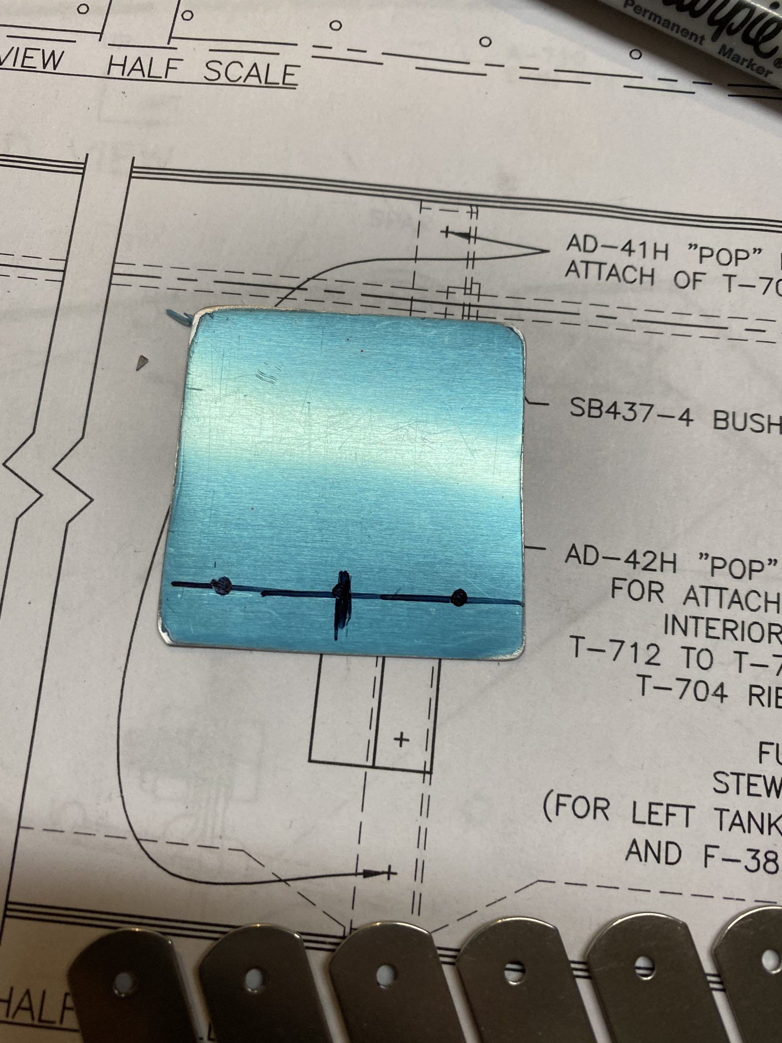
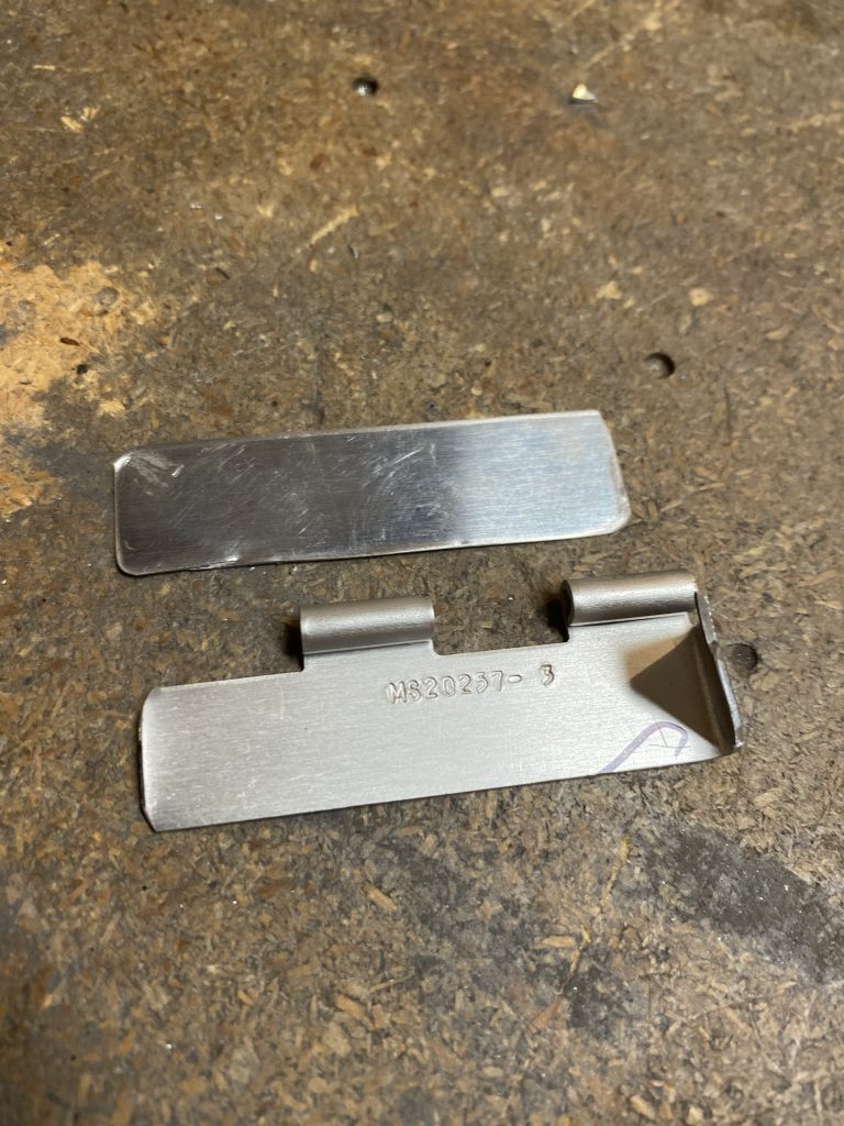
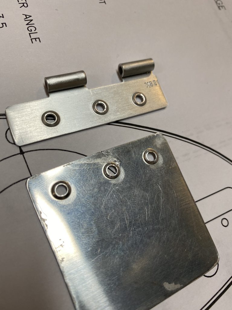
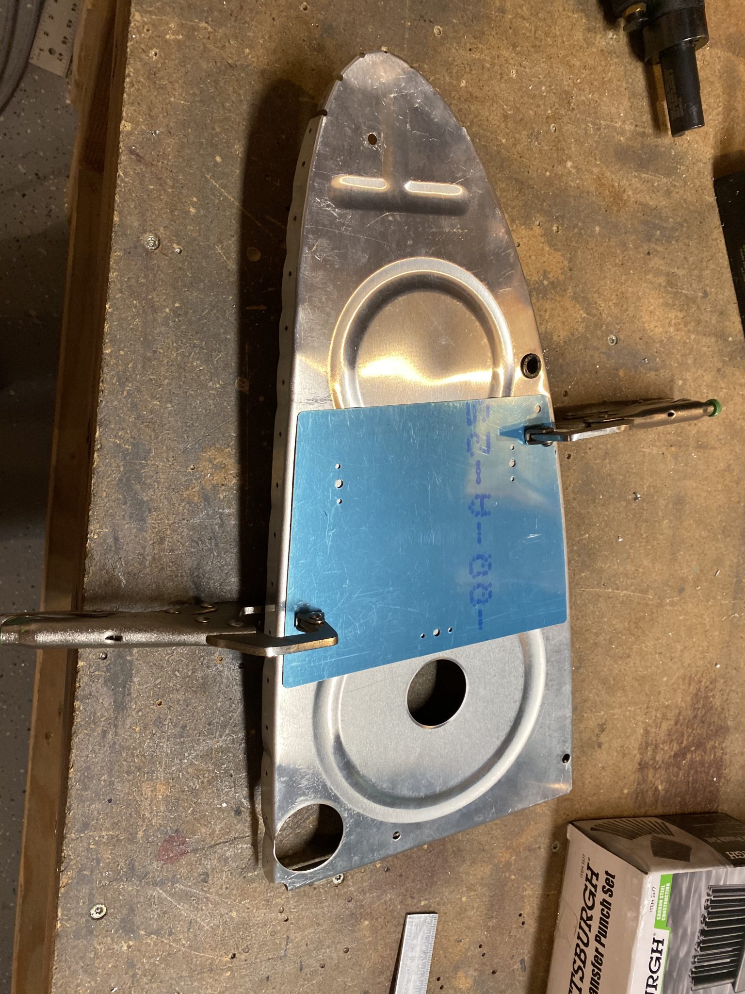
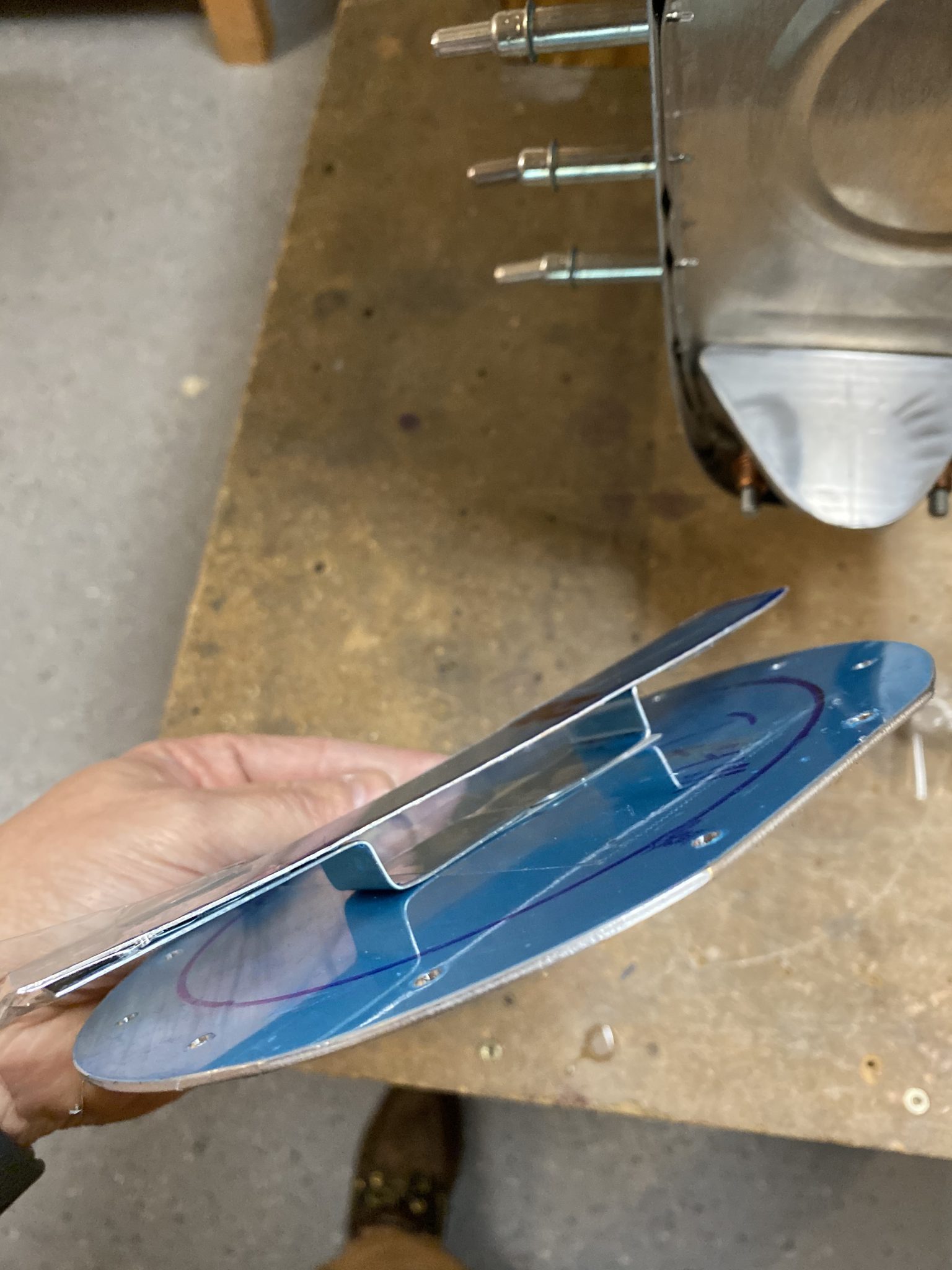
I wish I had snapped some more photos of the actual process of making this silly thing, but I kind of got into the “zone” and forgot to take some until it was nearly done. The little black marking on the upper left of the bracket is where I needed to trim the corner ever so slightly to make room for a rivet that is in a nearby hole. I did indeed make that trim and then tested it for fitment. Next up was to fabricate the trap door that holds the fuel into the inboard fuel bay so it doesn’t drain outboard when you are inverted or doing knife edge flight. The plans tell us to make this out of some 0.020″ alclad thats 1.75″ x 1.75″ and a piece of piano hinge. We have this to go by in the plans as well:

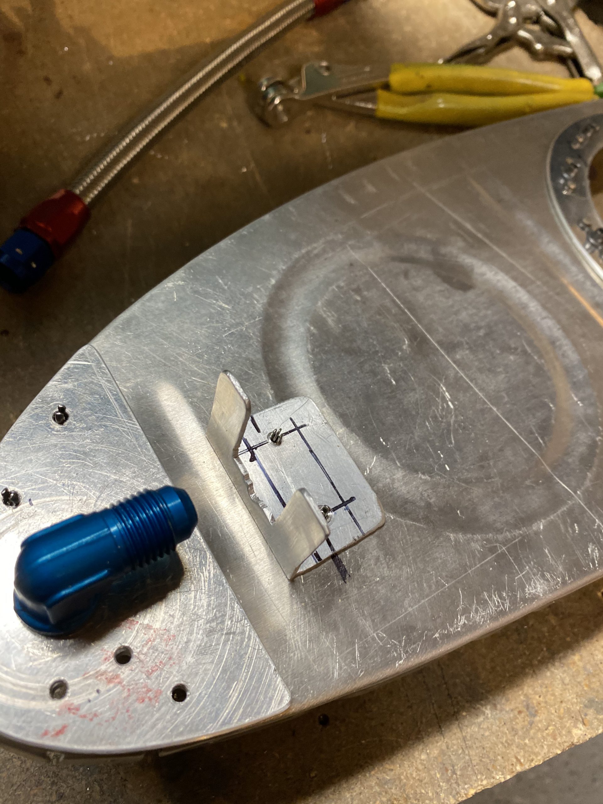
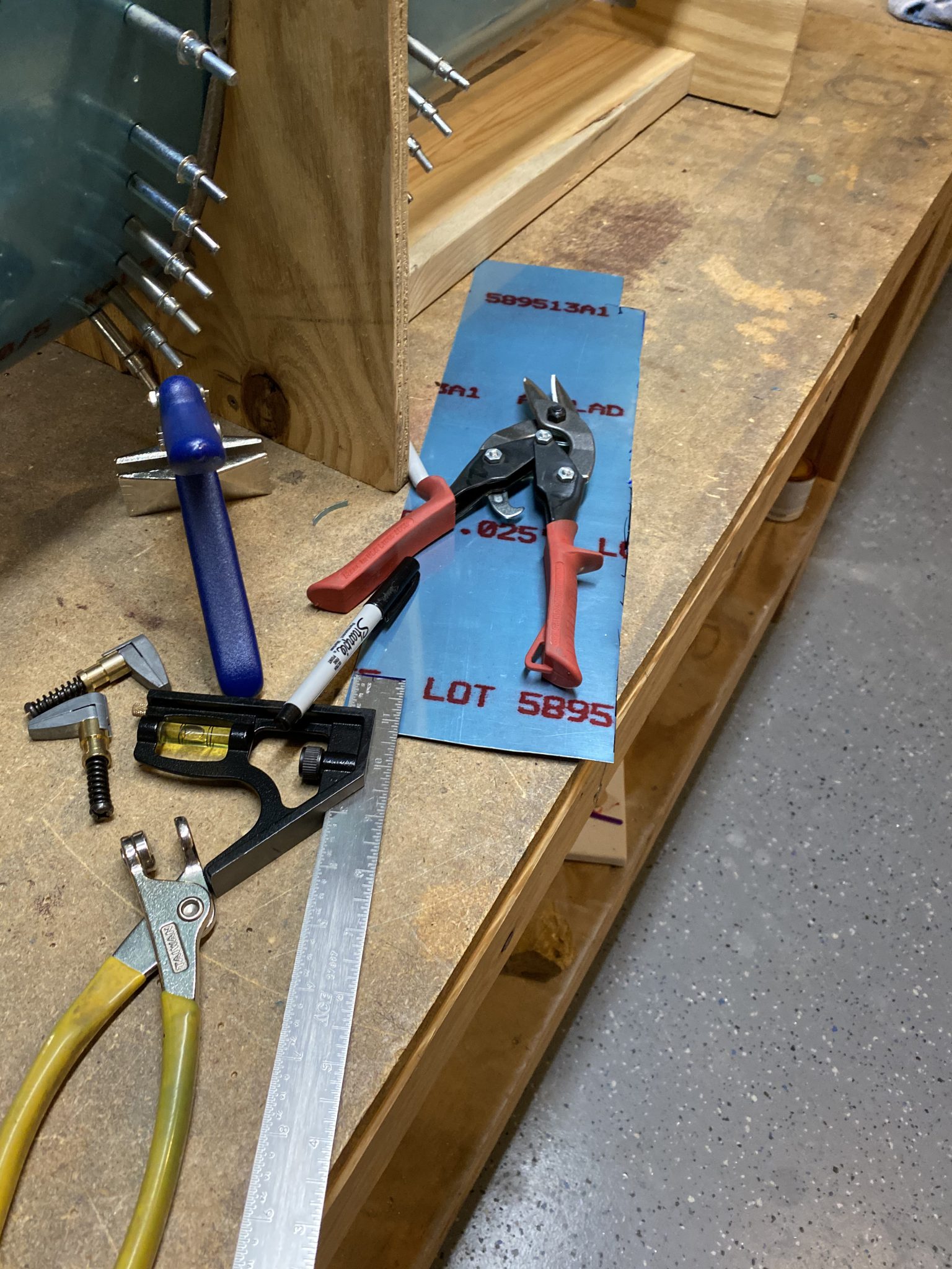
Which is pretty easy to go by. So, I went digging in my scrap bucket for some 0.020″ alclad, marked up a little piece and snipped it out with my snips. I did the same for the piano hinge, luckily I had a piece almost the right size in my scrap bucket.

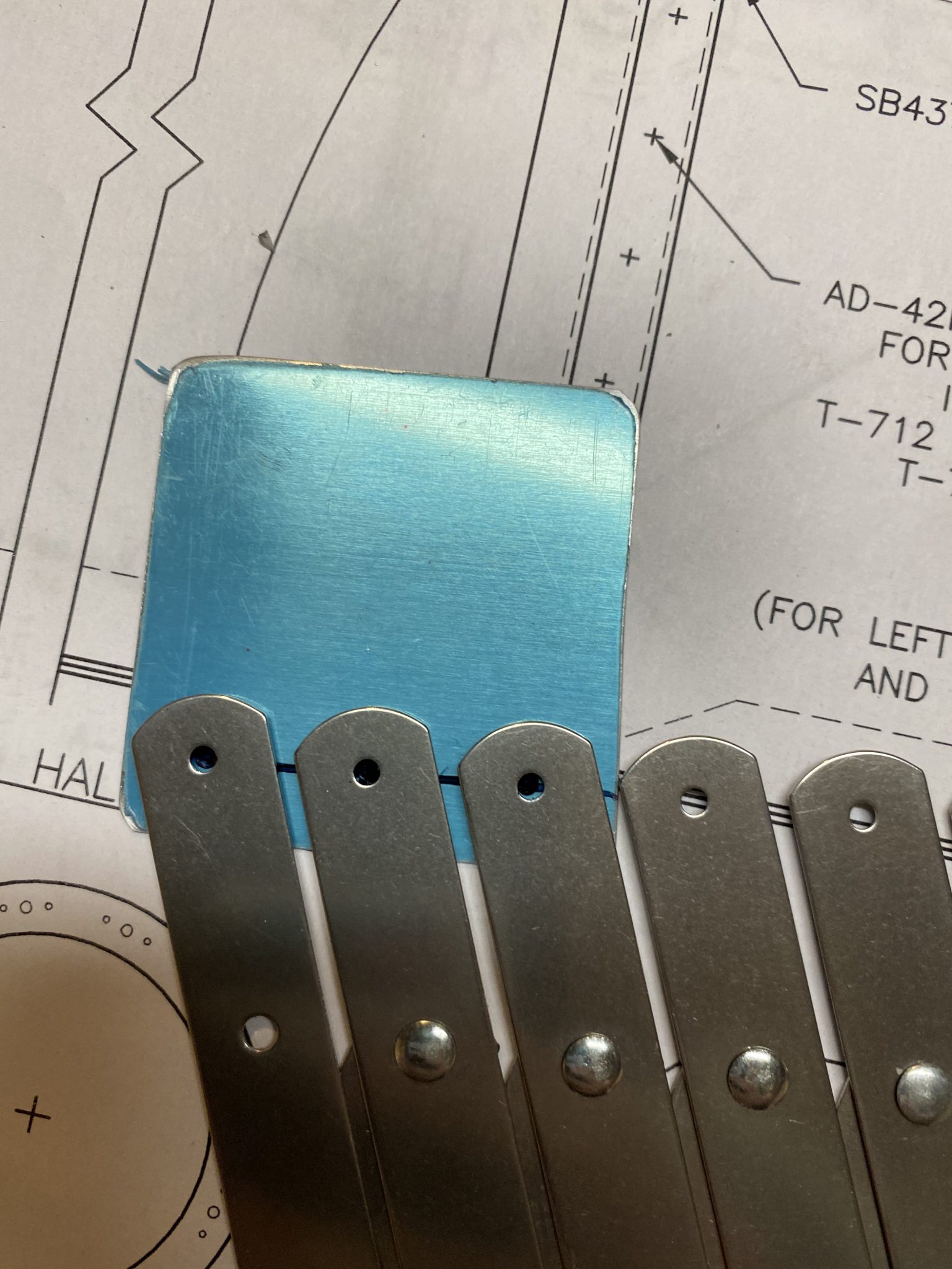
Then I measured for edge distance, and marked a reference line, broke out my rivet fan spacer and marked up three rivets holes, then drilled them.


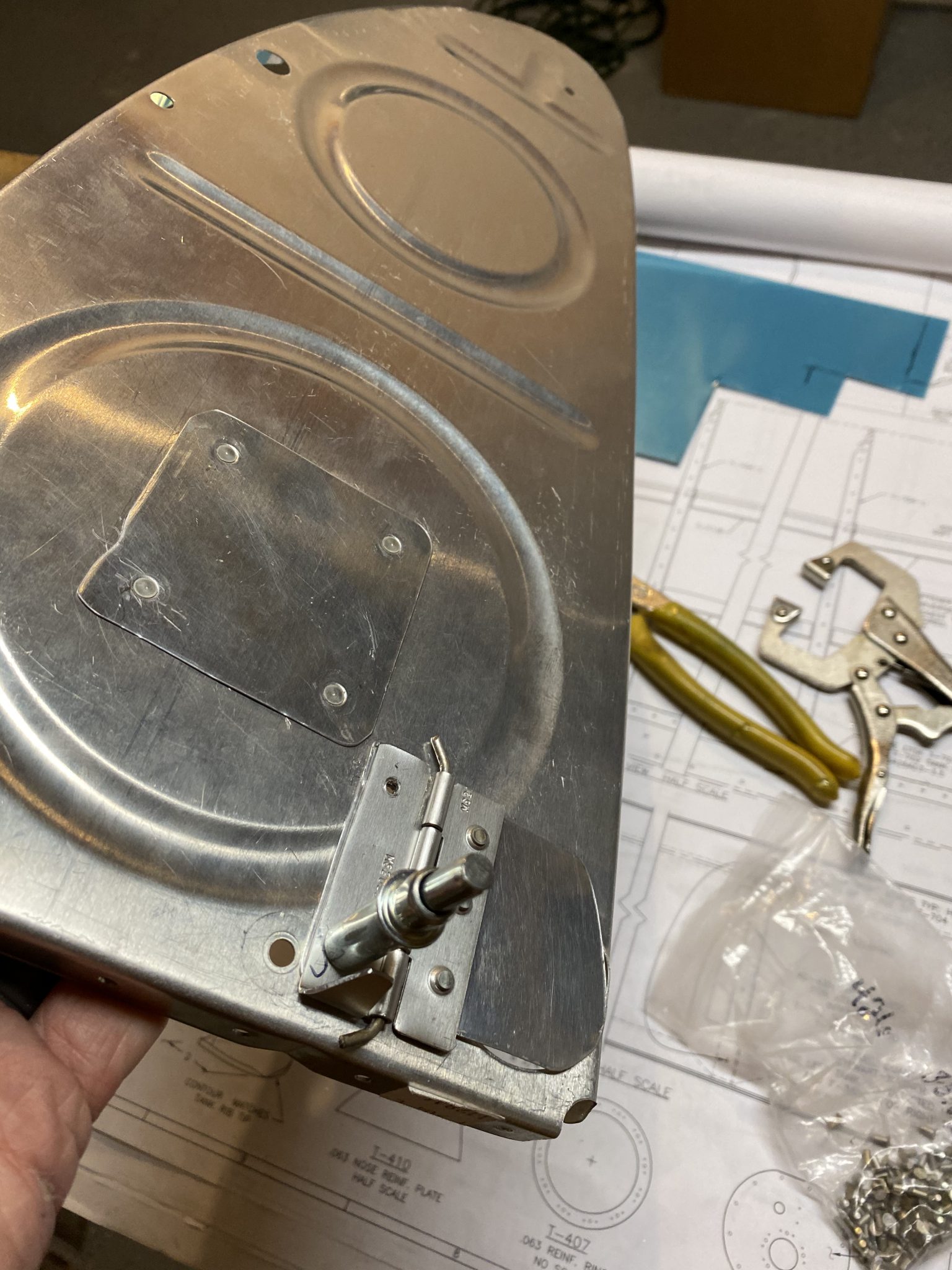
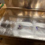
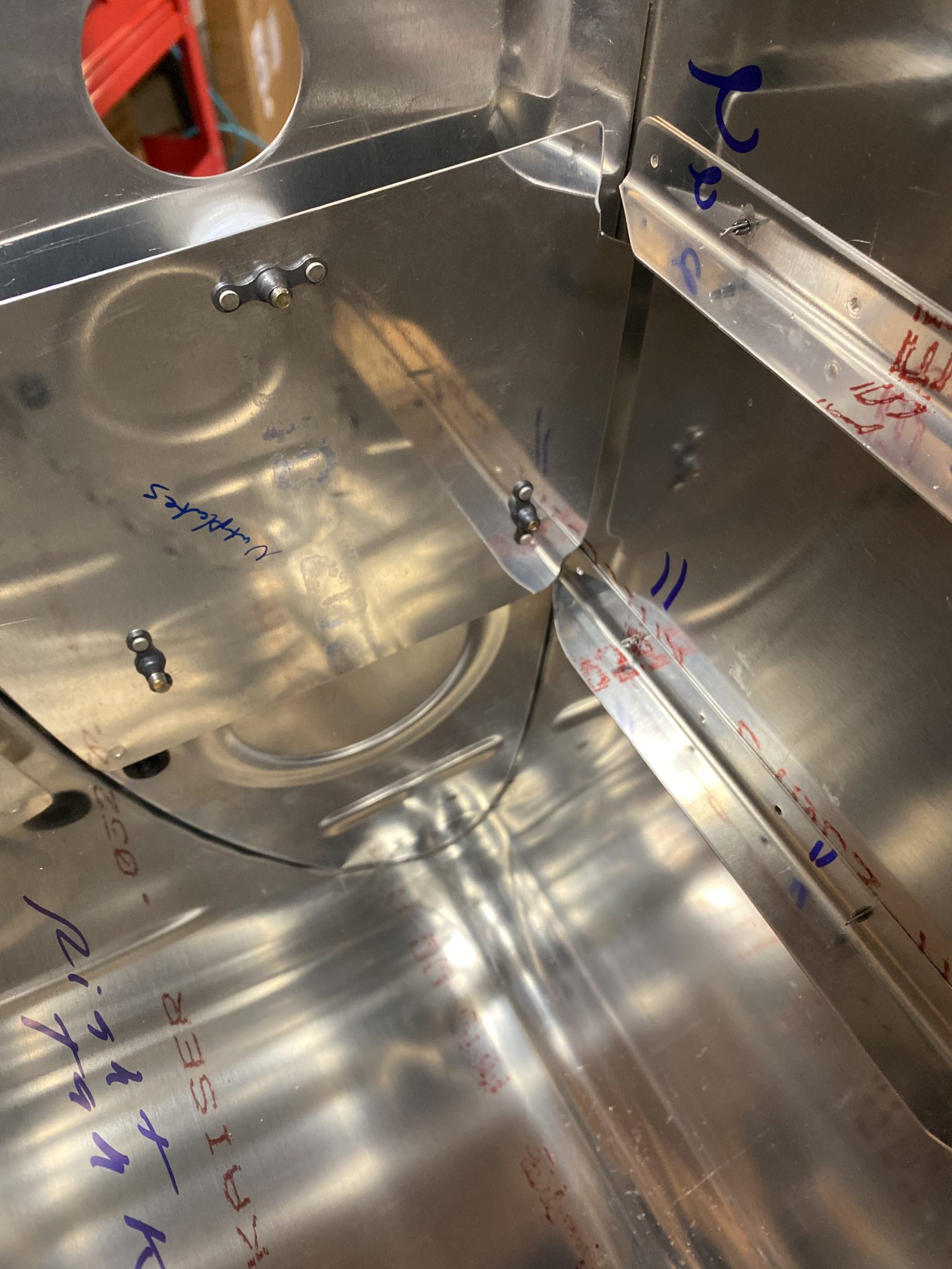
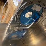
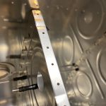
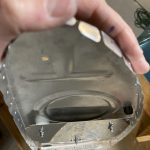
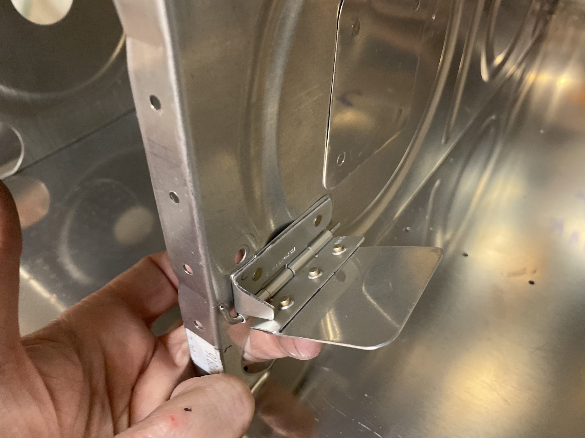
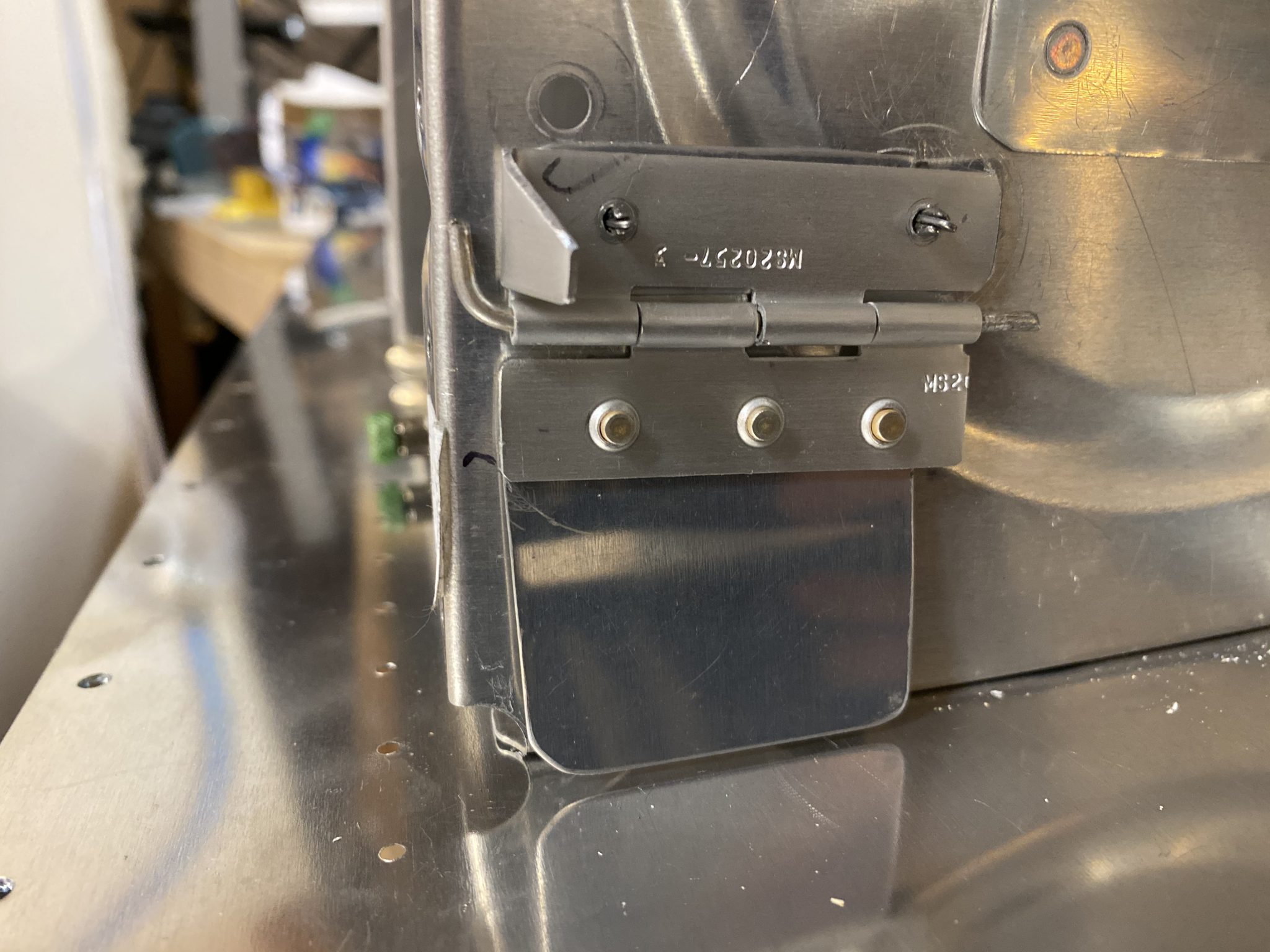
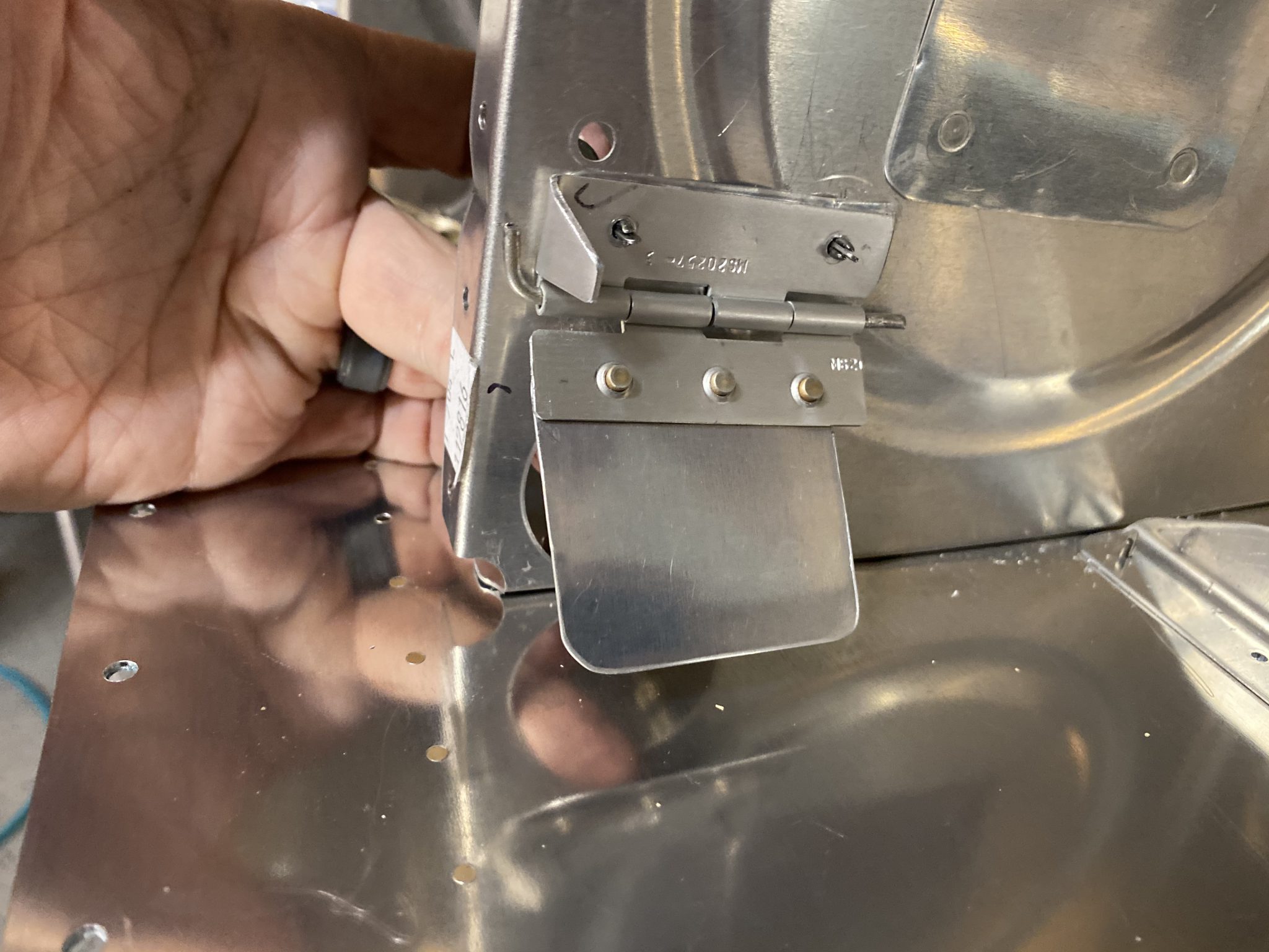
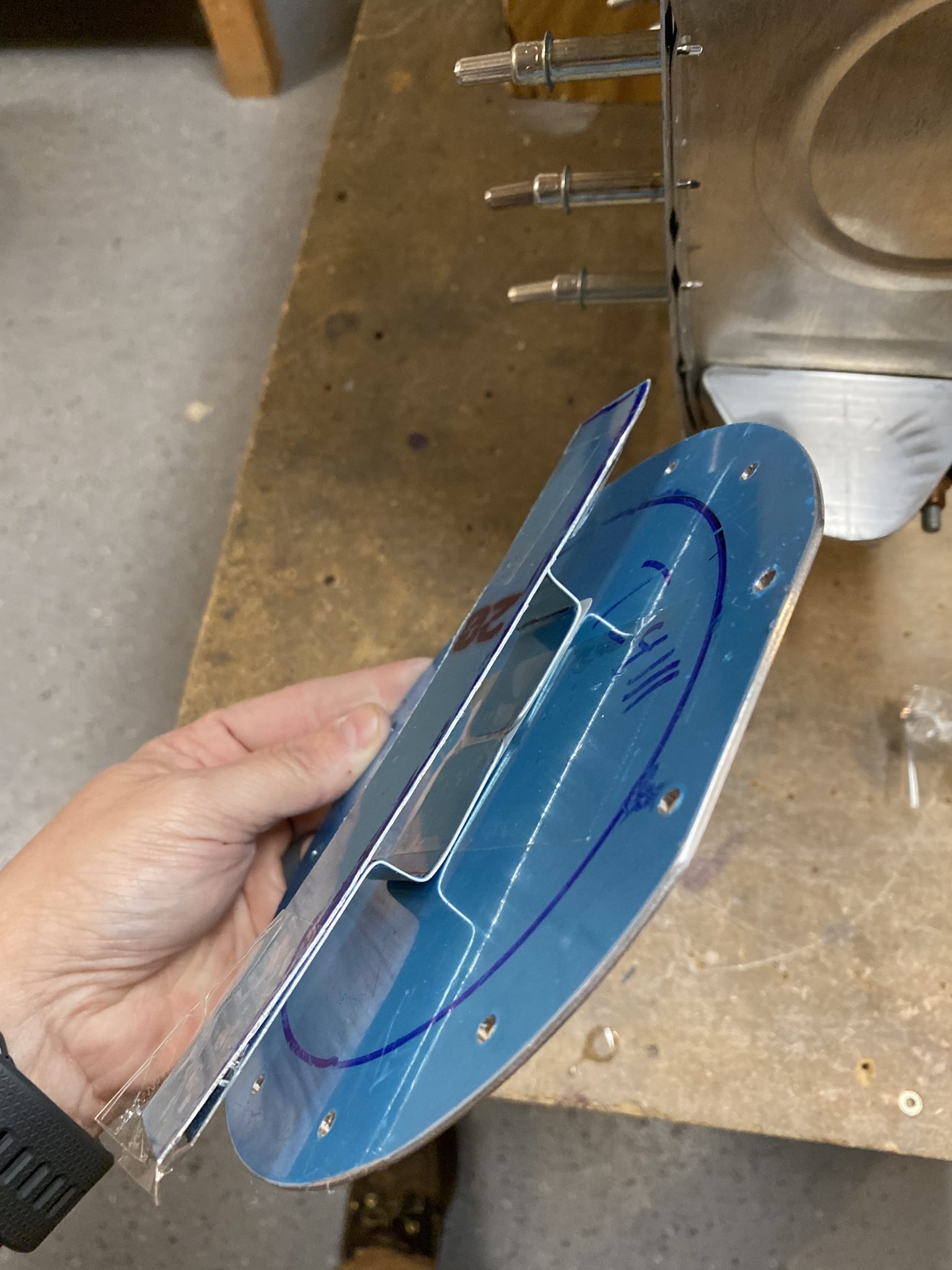
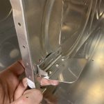
Once I had the trap door drilled, I trimmed my piano hinge and fitted it where it would work best, trimmed it to the right size and bent the little tang to serve as a stop to keep the flap from flopping all the way up. I also decided to cut a little spacer of 0.020″ to go behind the top hinge to help the trap door sit totally flush against the rib. If i hadn’t done this, the top of the hinge would have been sitting right against the rib. while the bottom of the hinge would have been angled slightly because of the flap riveted to it.
Then I dimpled the flap and the hinge so I could use flush rivets to help keep the flap sitting nice and flush against the rib.
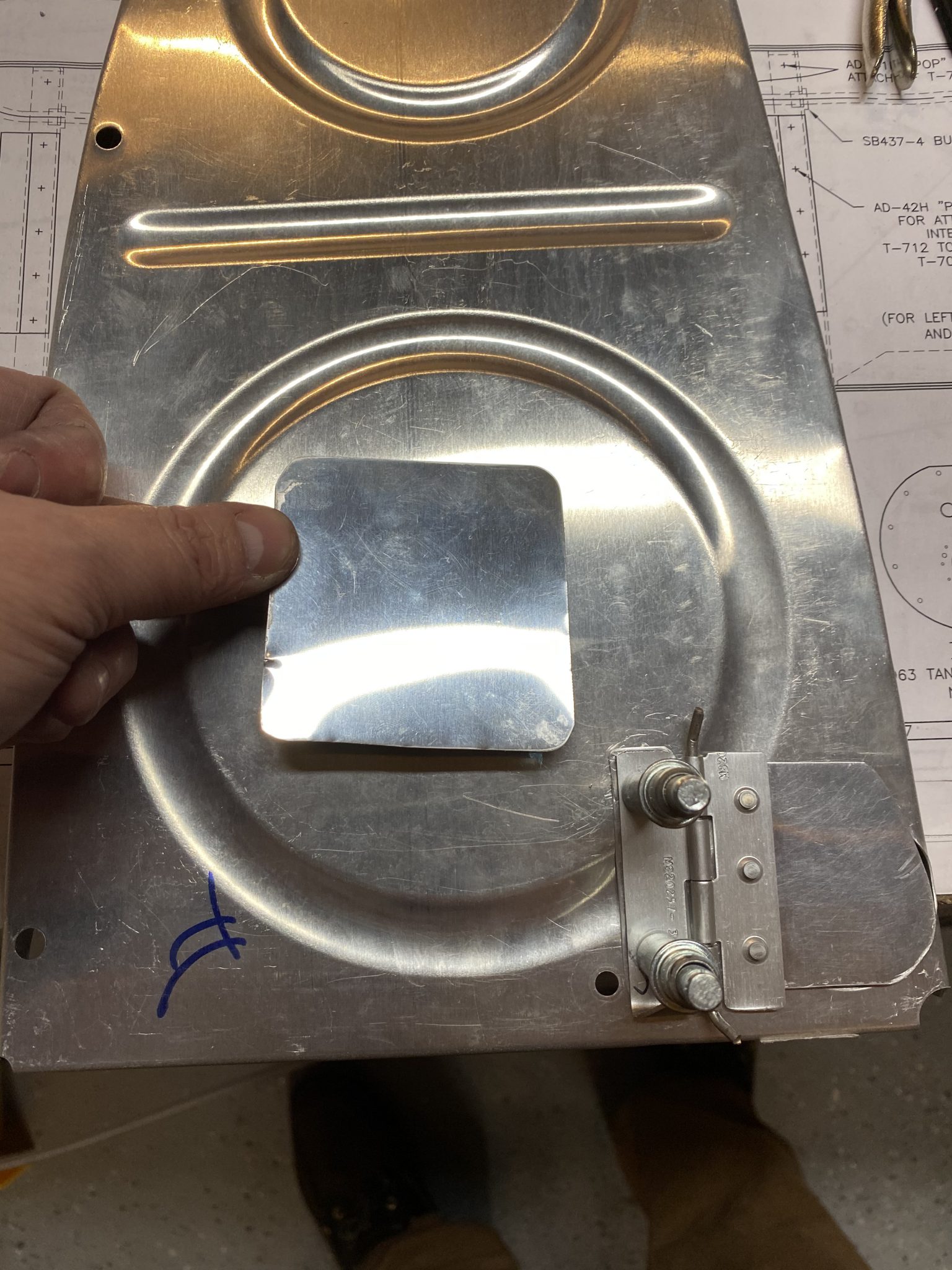
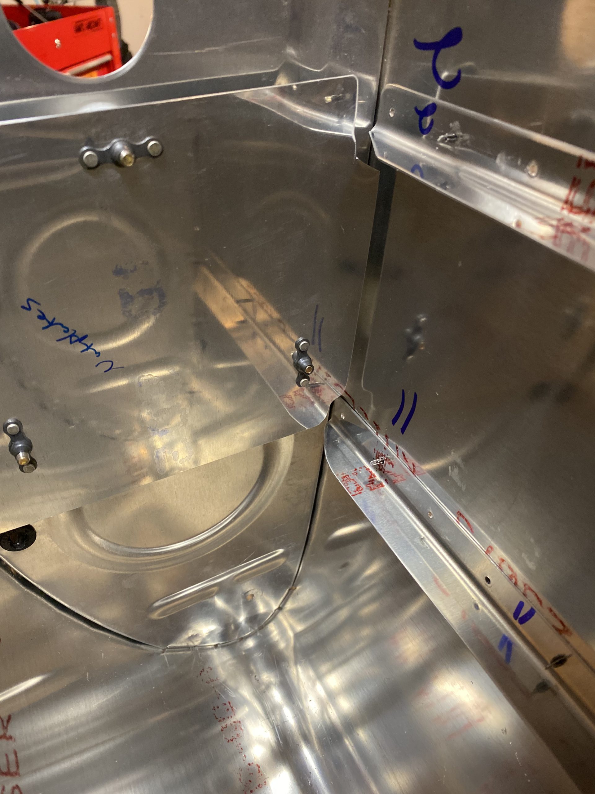
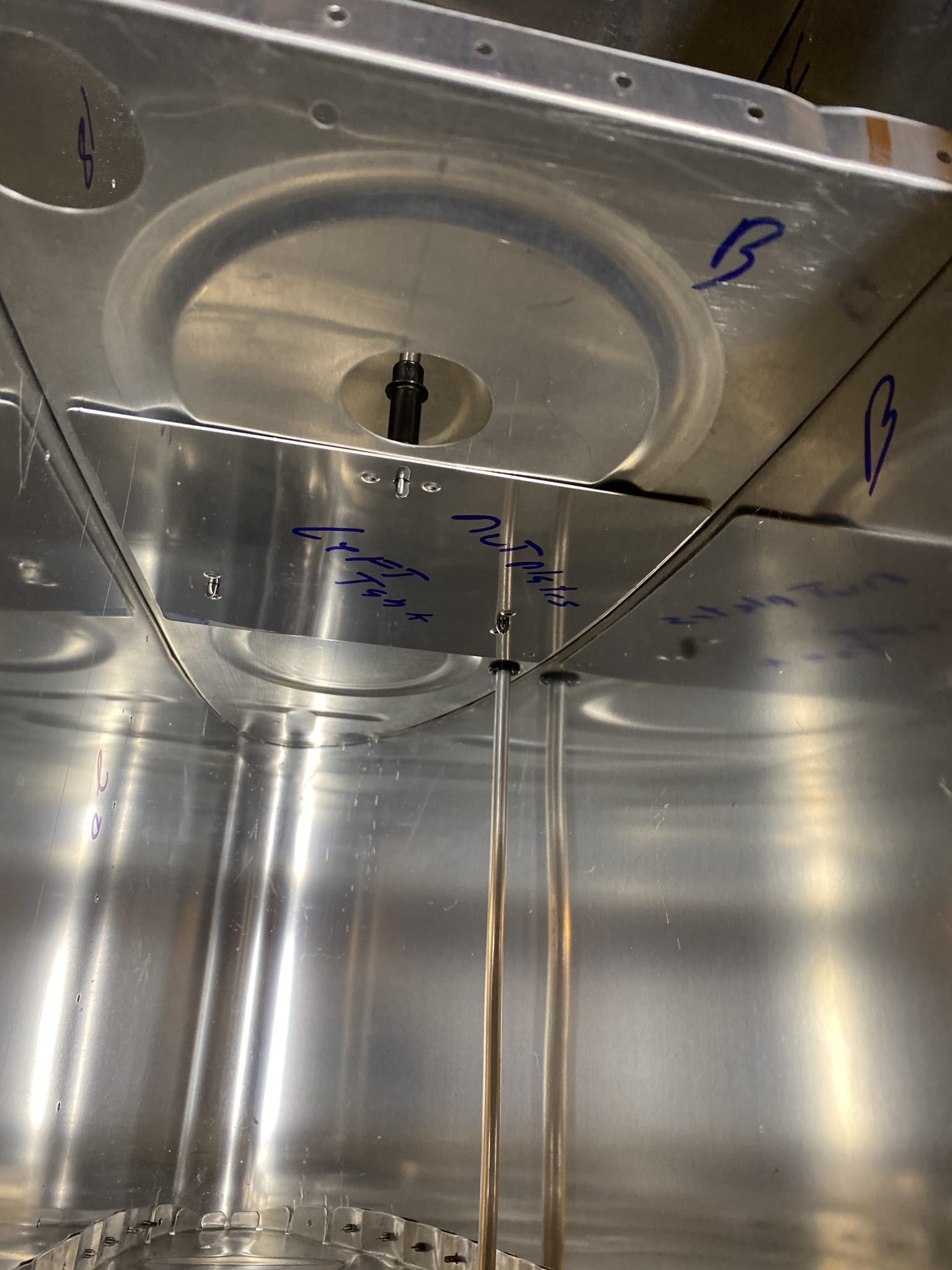
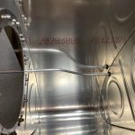
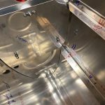
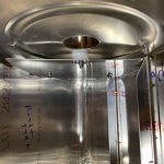
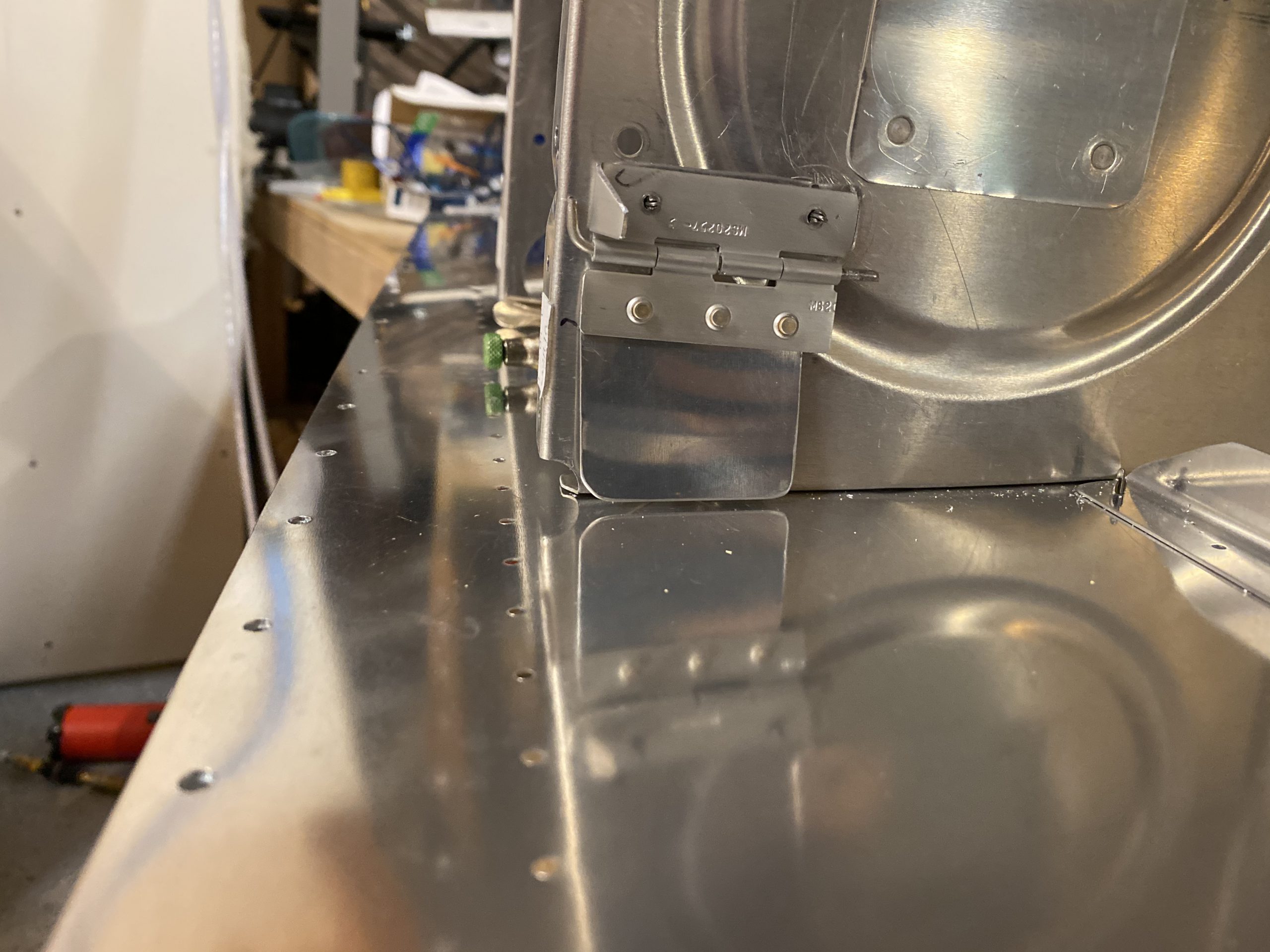
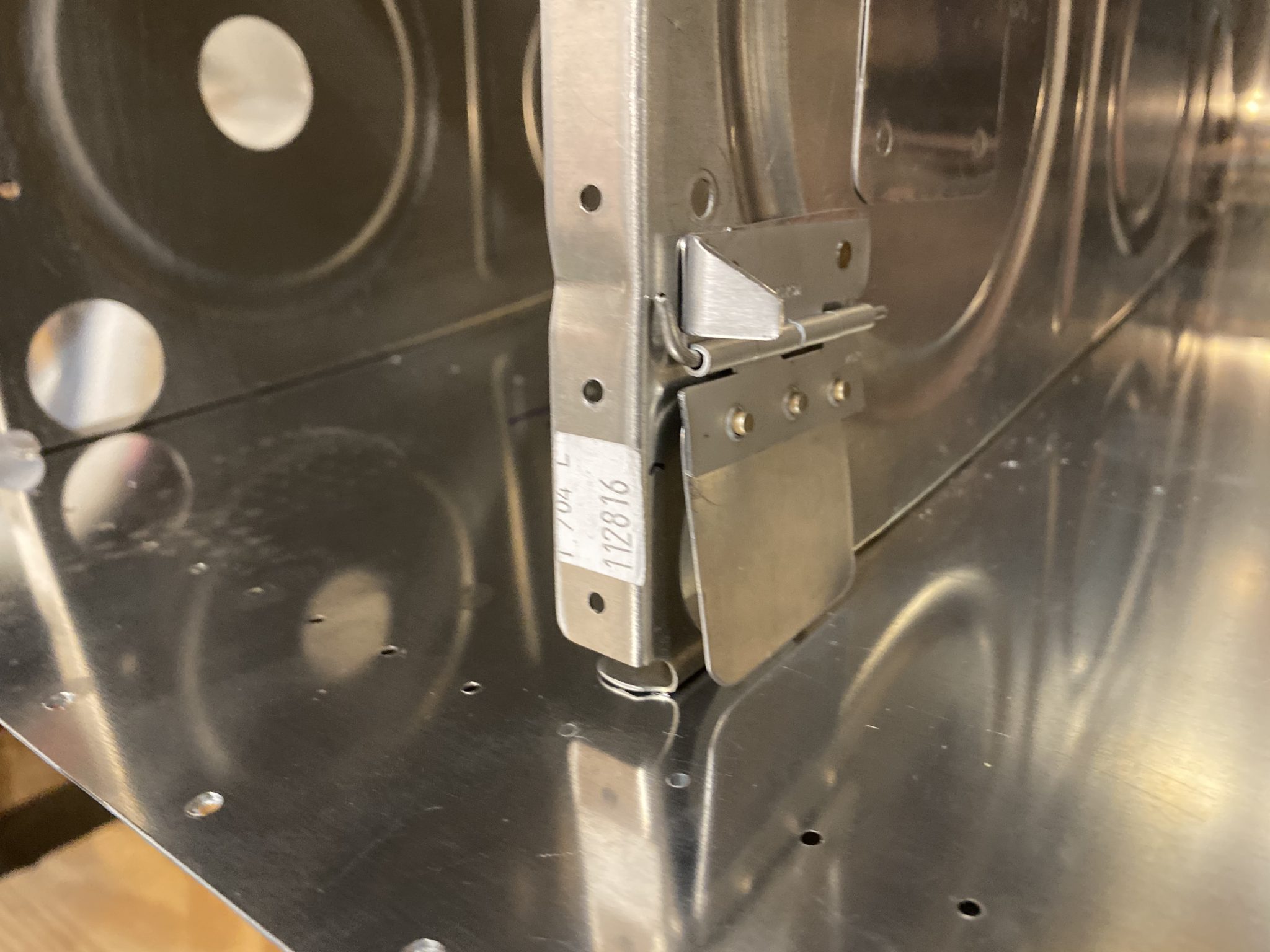
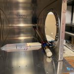
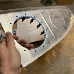
Finally, I riveted the flap onto it’s section of hinge using my squeezer and some AN426AD3-3.5 rivets and clecoed it onto the rib with the spacer behind the top portion of the hinge. You can see how it works now. The spacer is the same thickness as the flapper on the trap door. This keeps the hinge pieces at the same height, and lets the trap door flapper swing very freely, and sit totally flush against the rib.
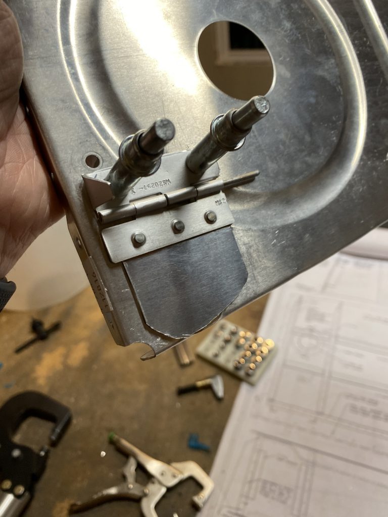
I also trimmed around the flapper a little towards the bottom, to keep the flap from getting hung up on any stray proseal that may happen to get down there when its time to seal it up. I want this little door to be able to swing totally freely, and then close completely when needed.
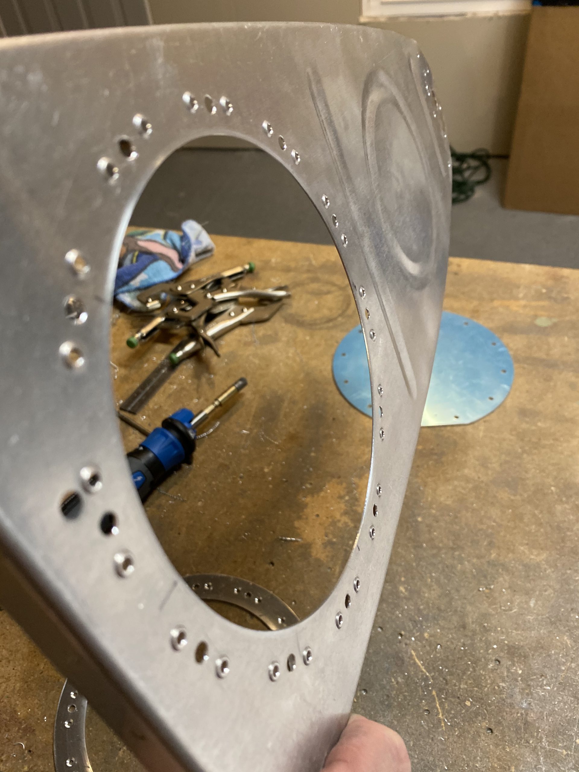
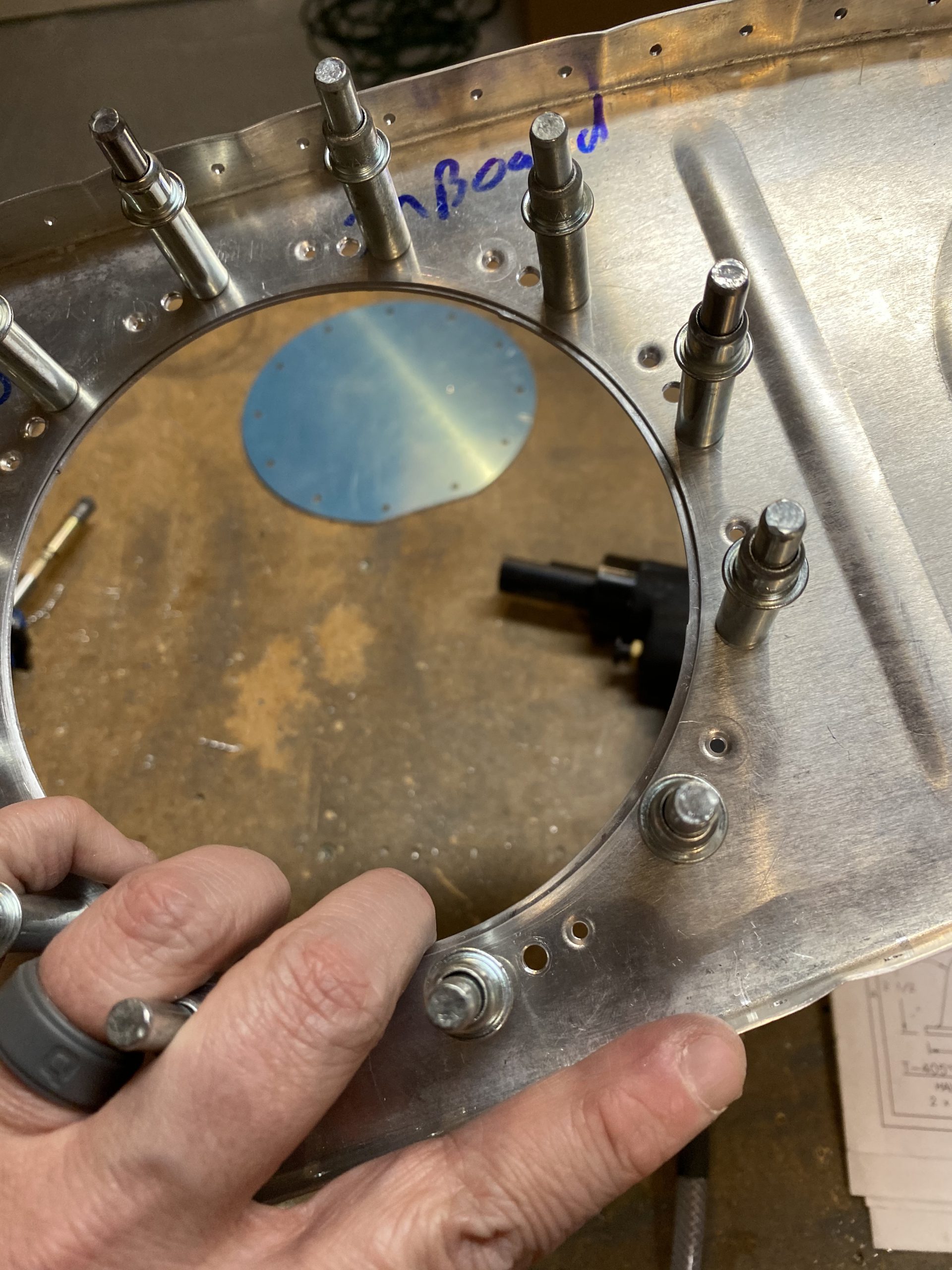
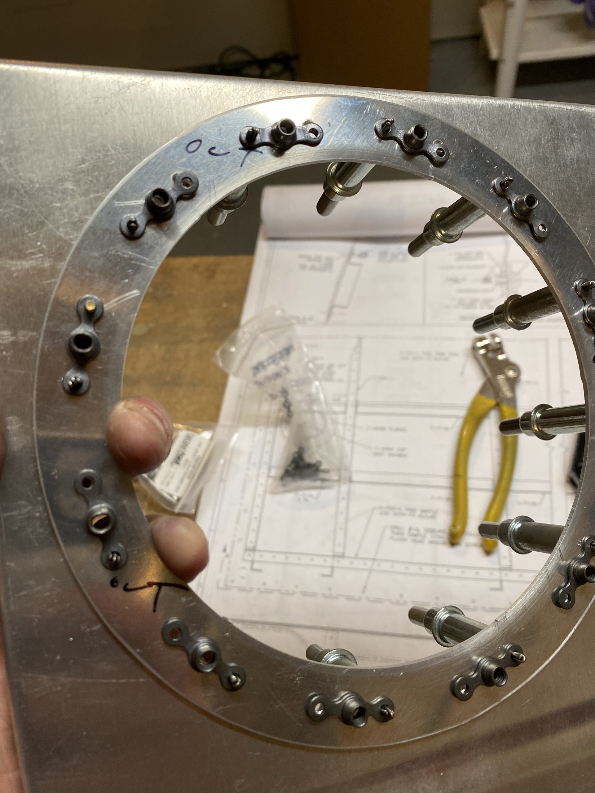
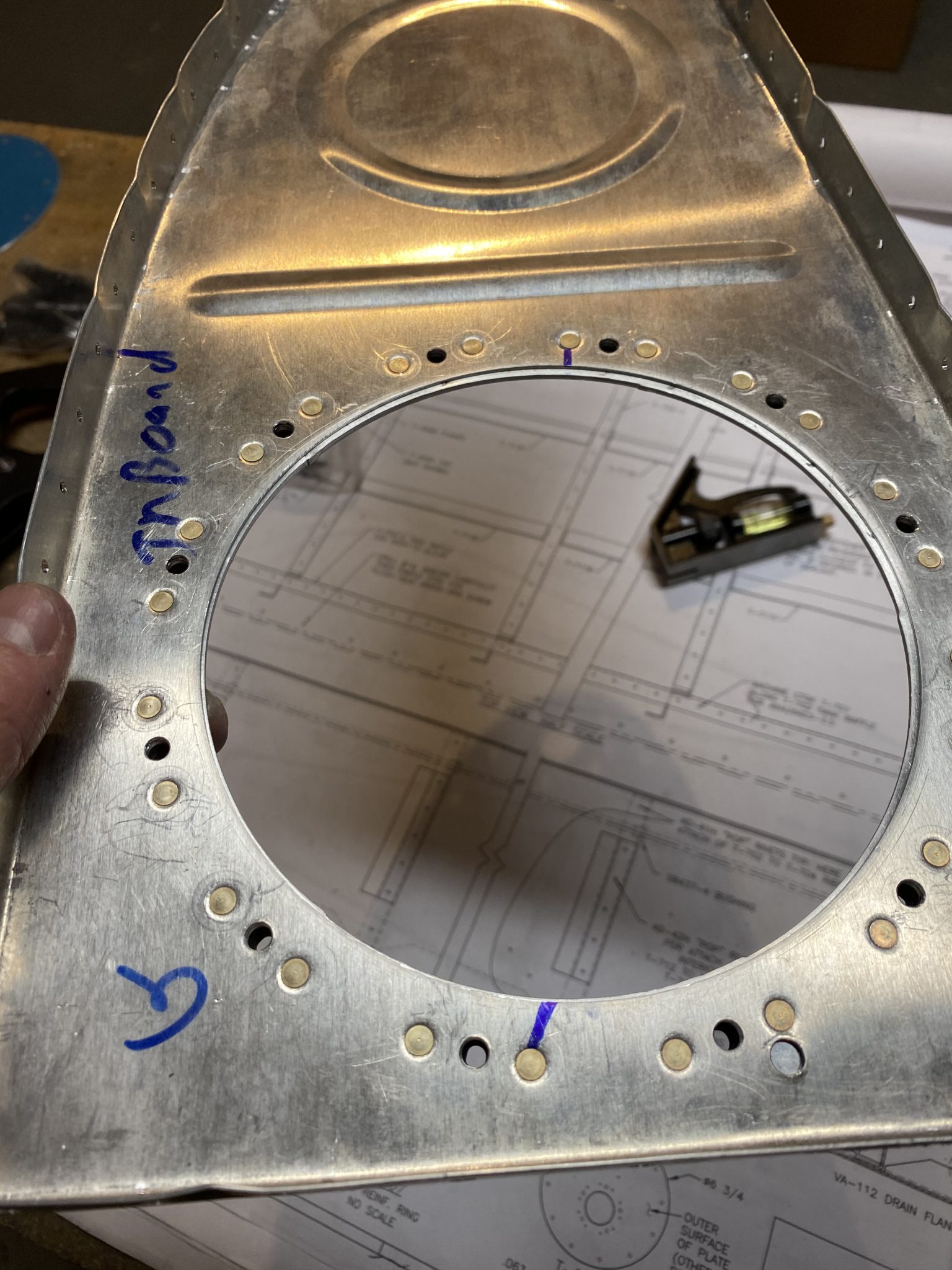
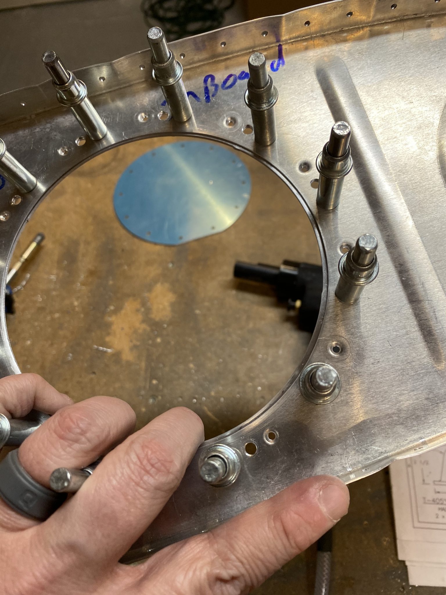
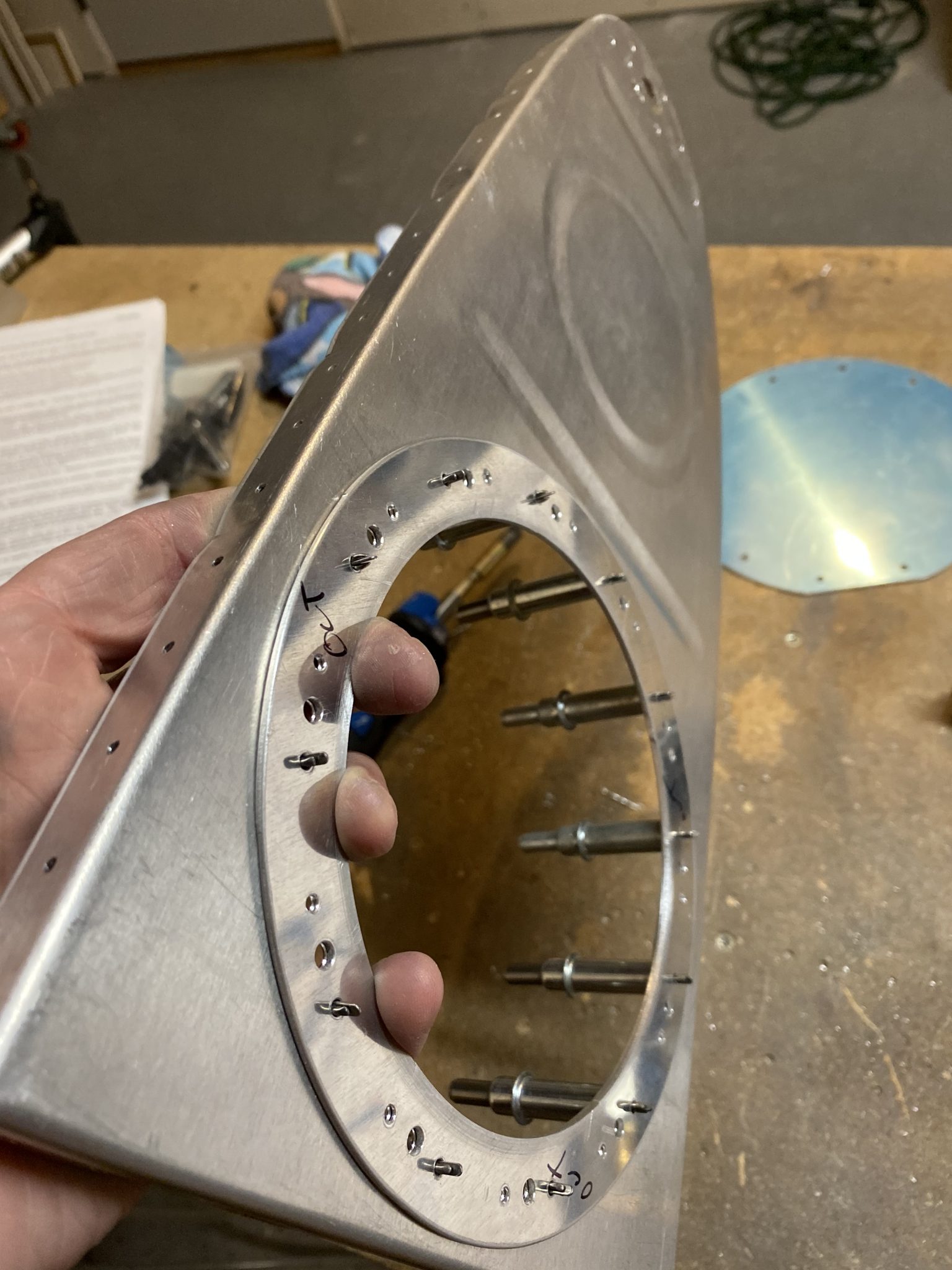
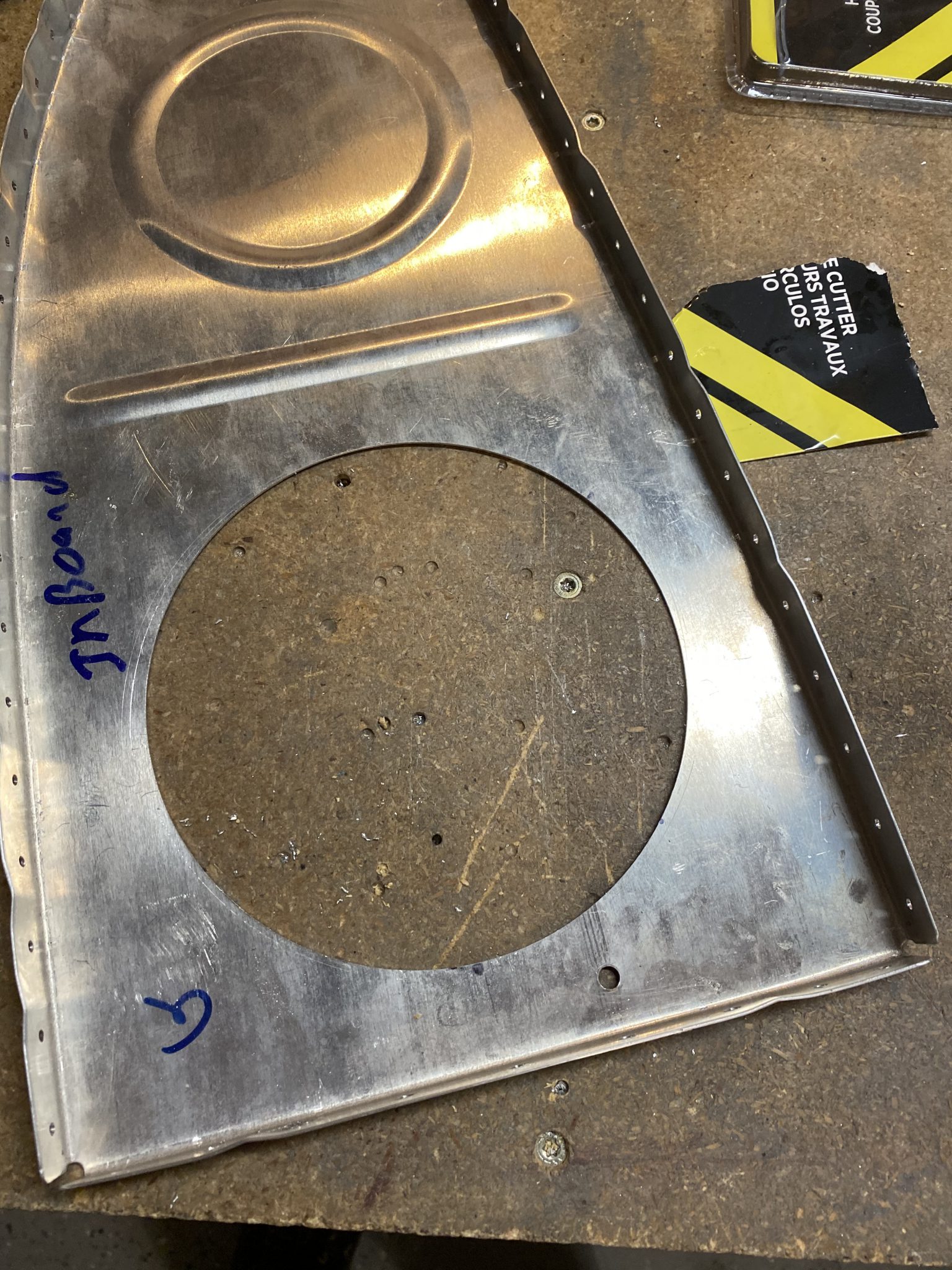
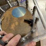
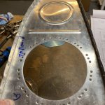
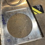
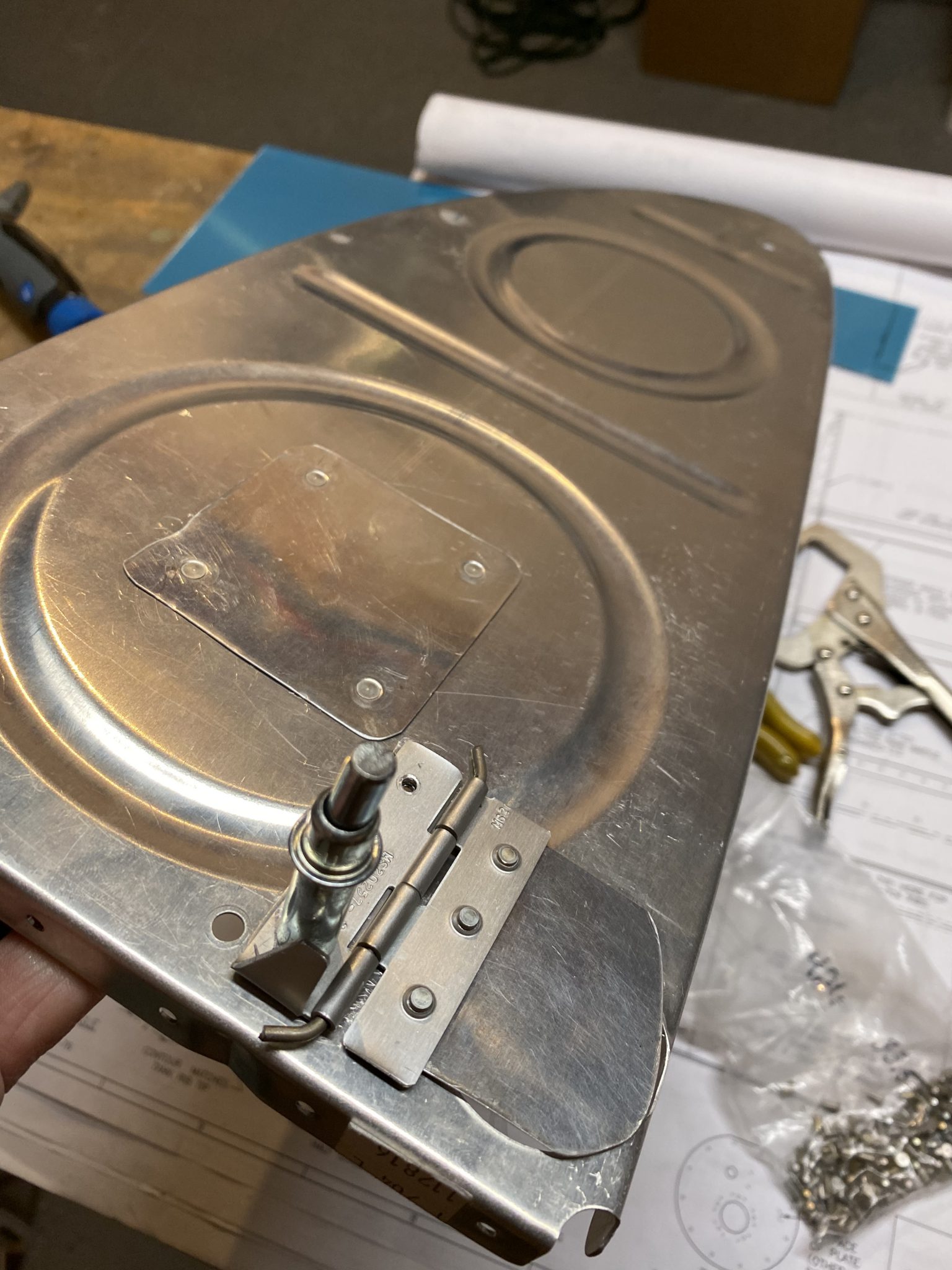
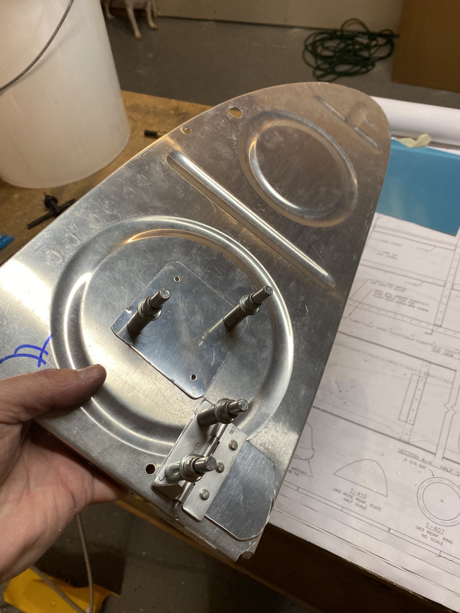
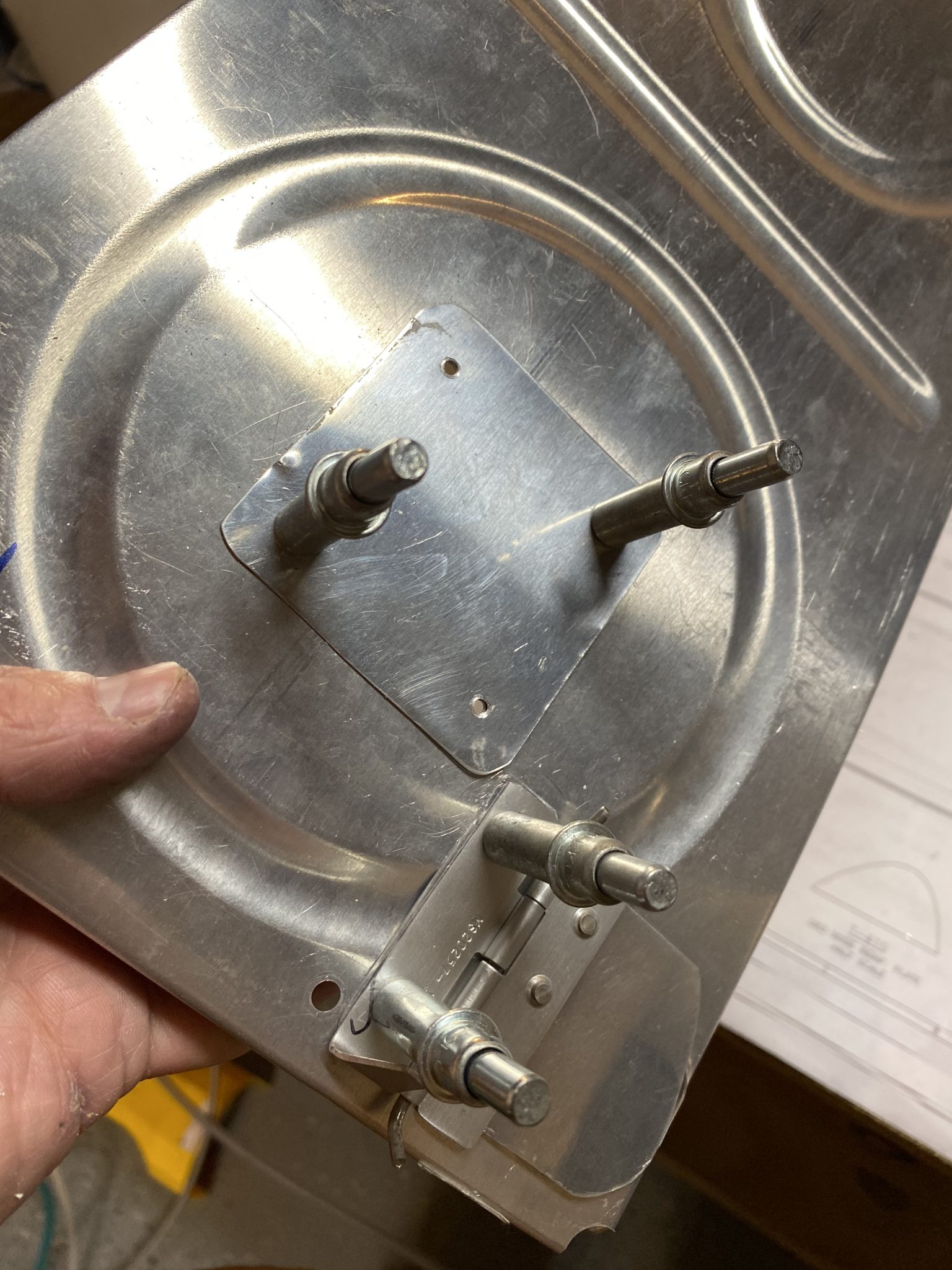
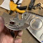
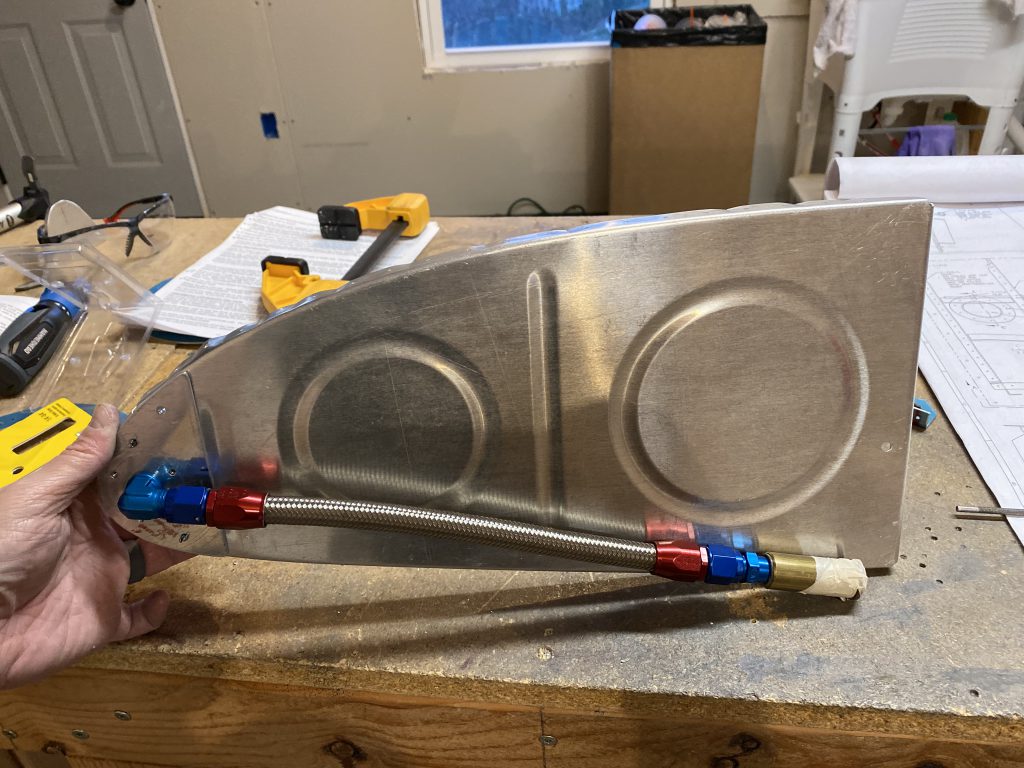
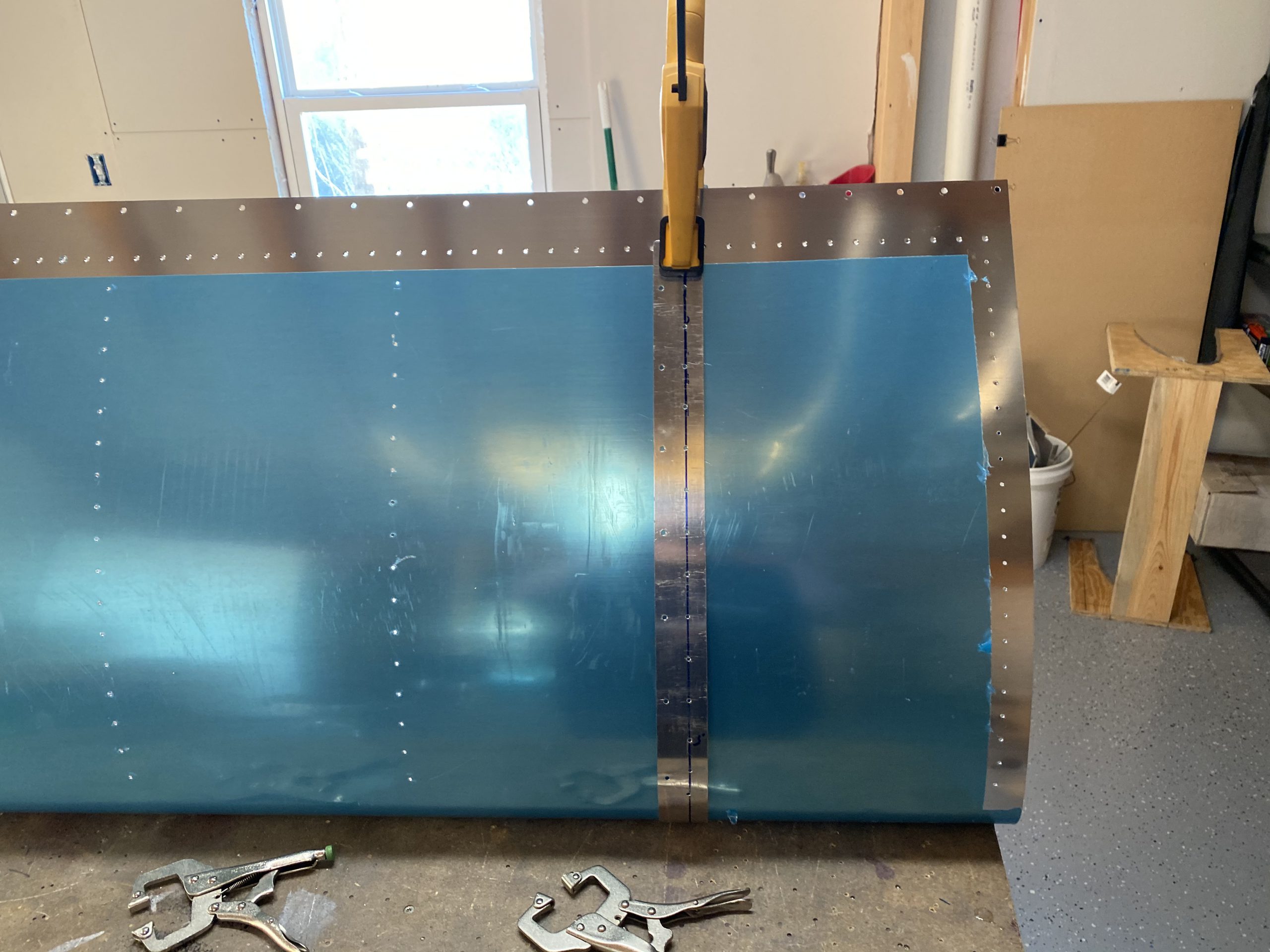
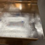
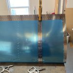
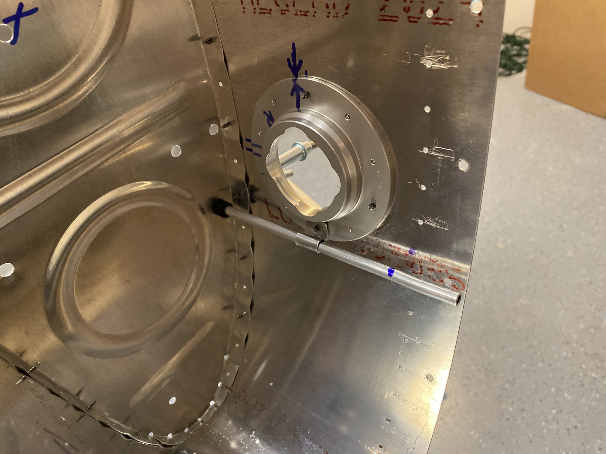
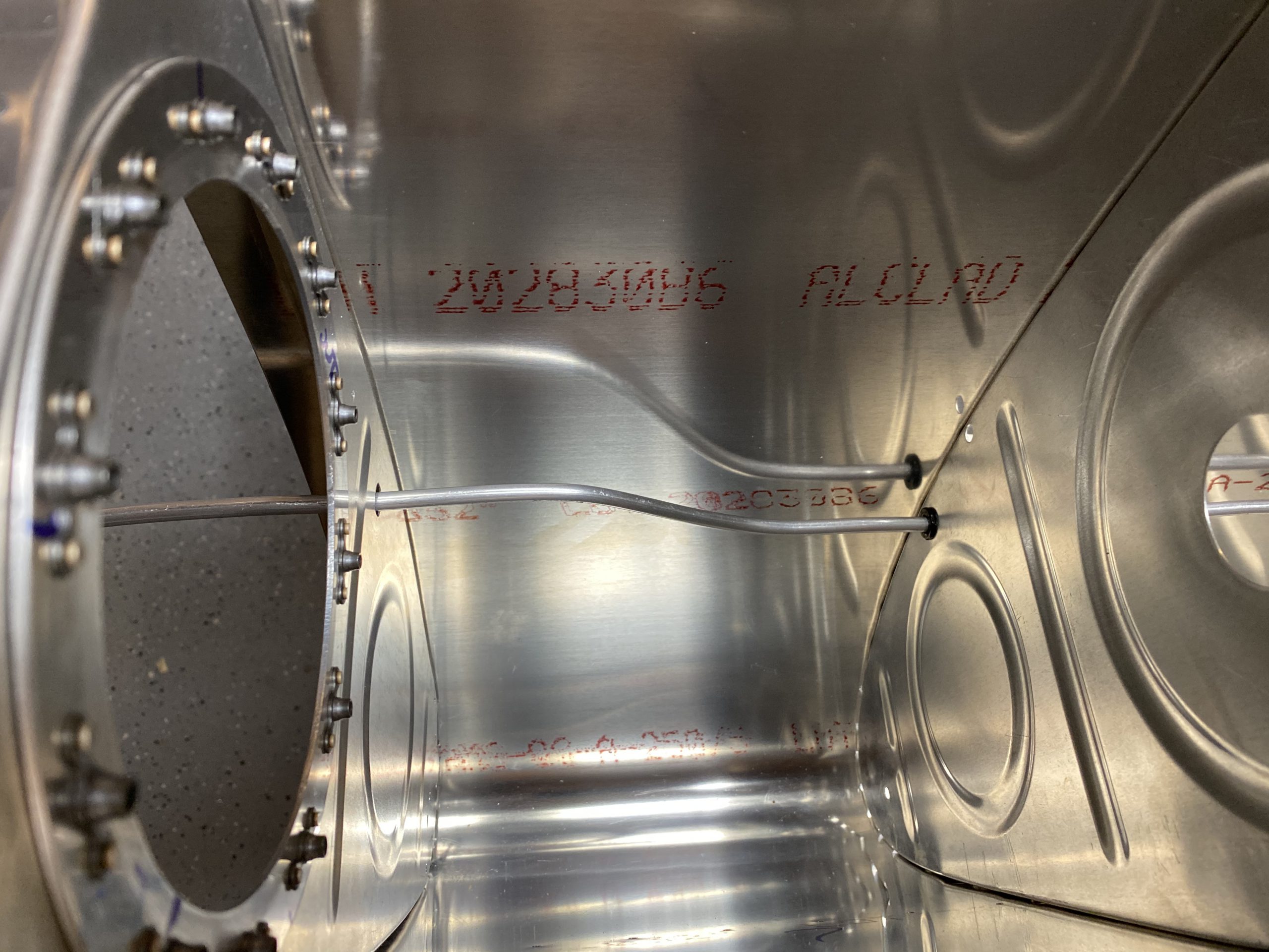
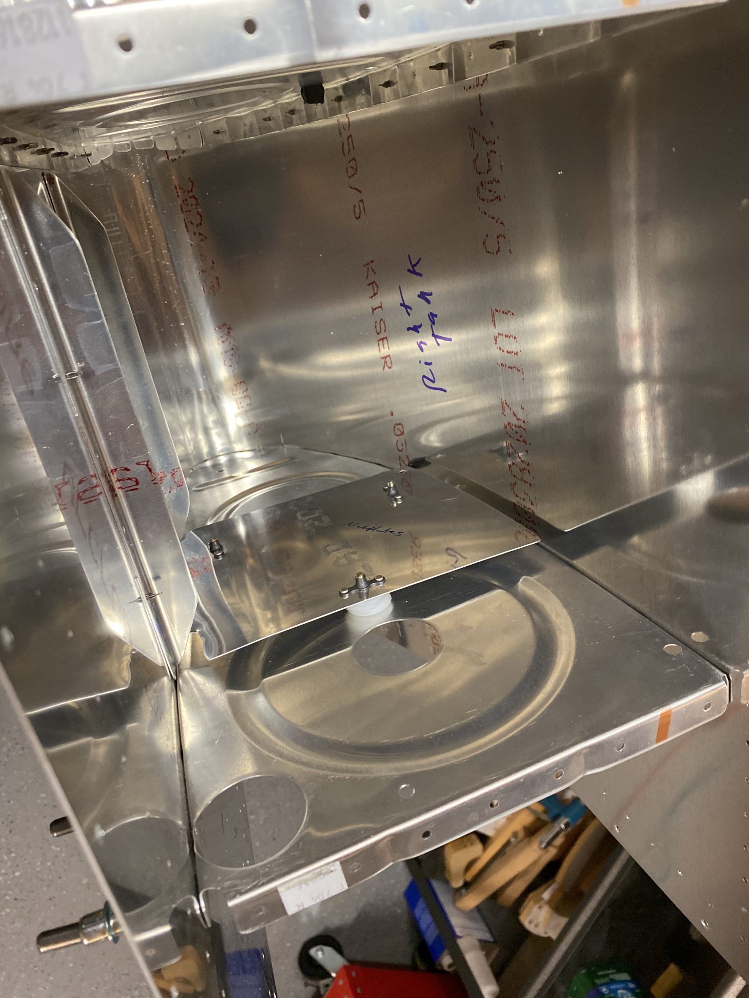
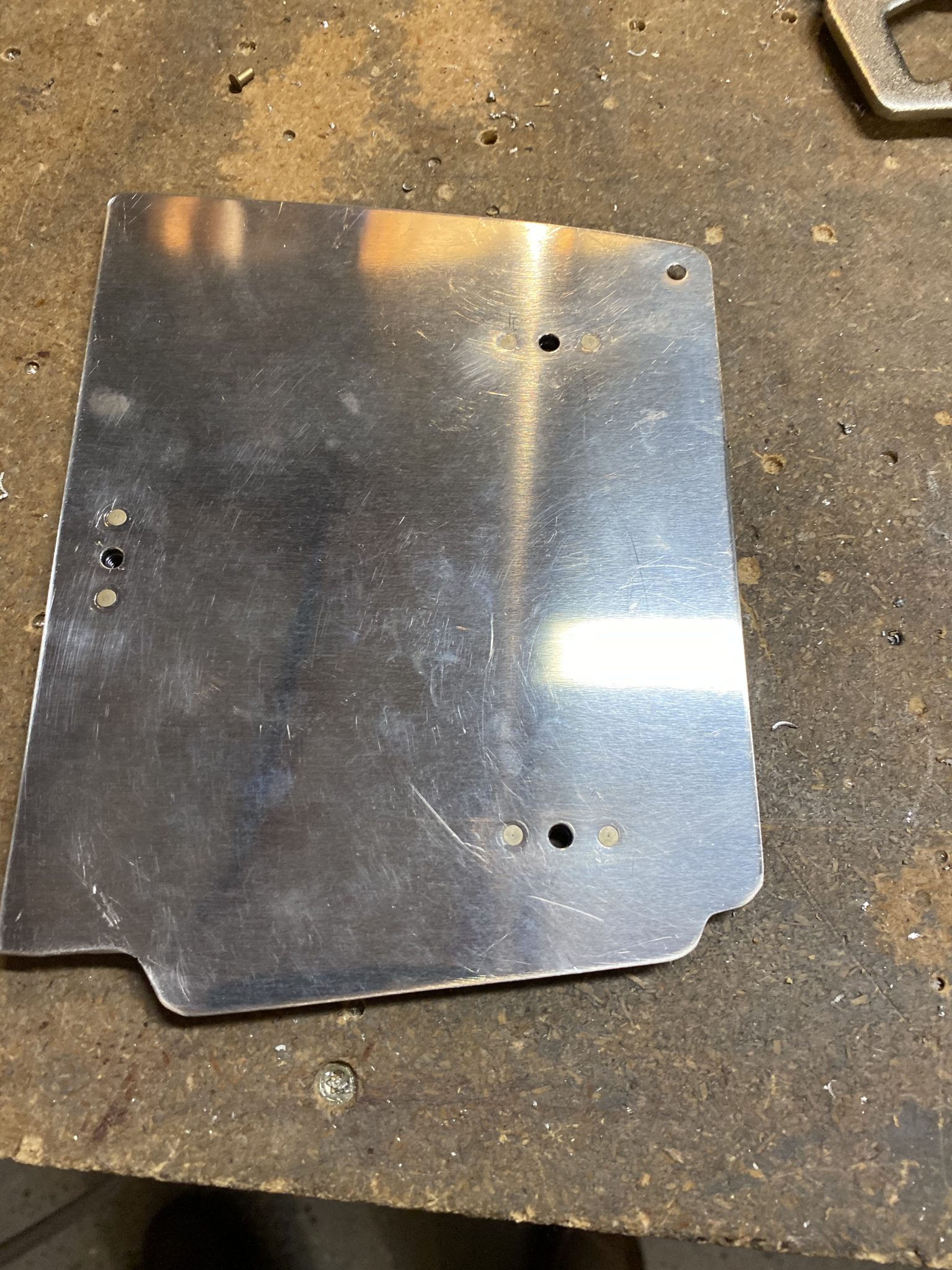
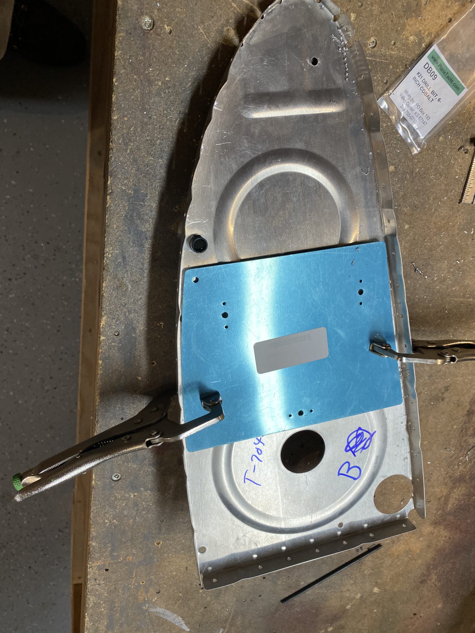
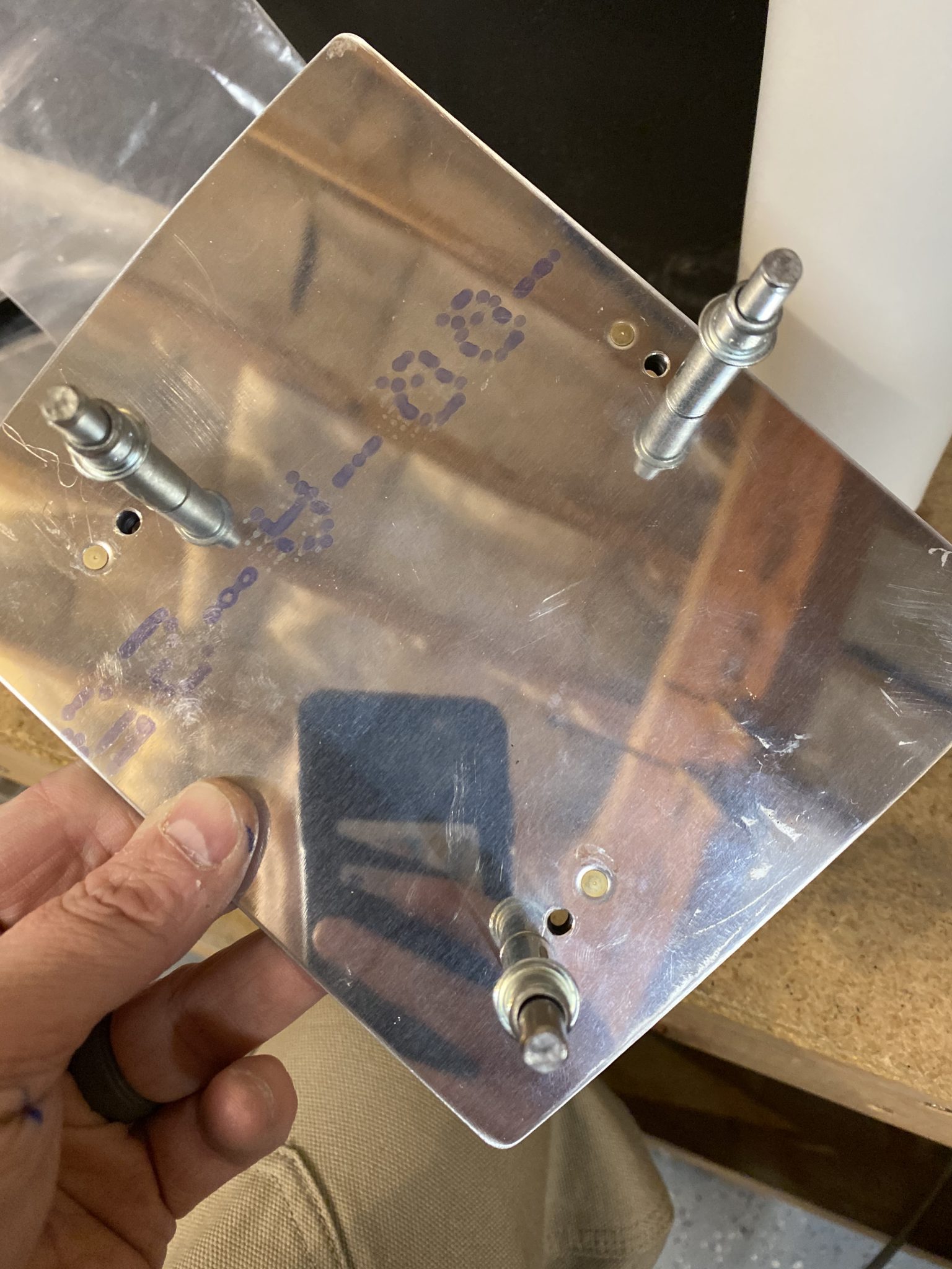
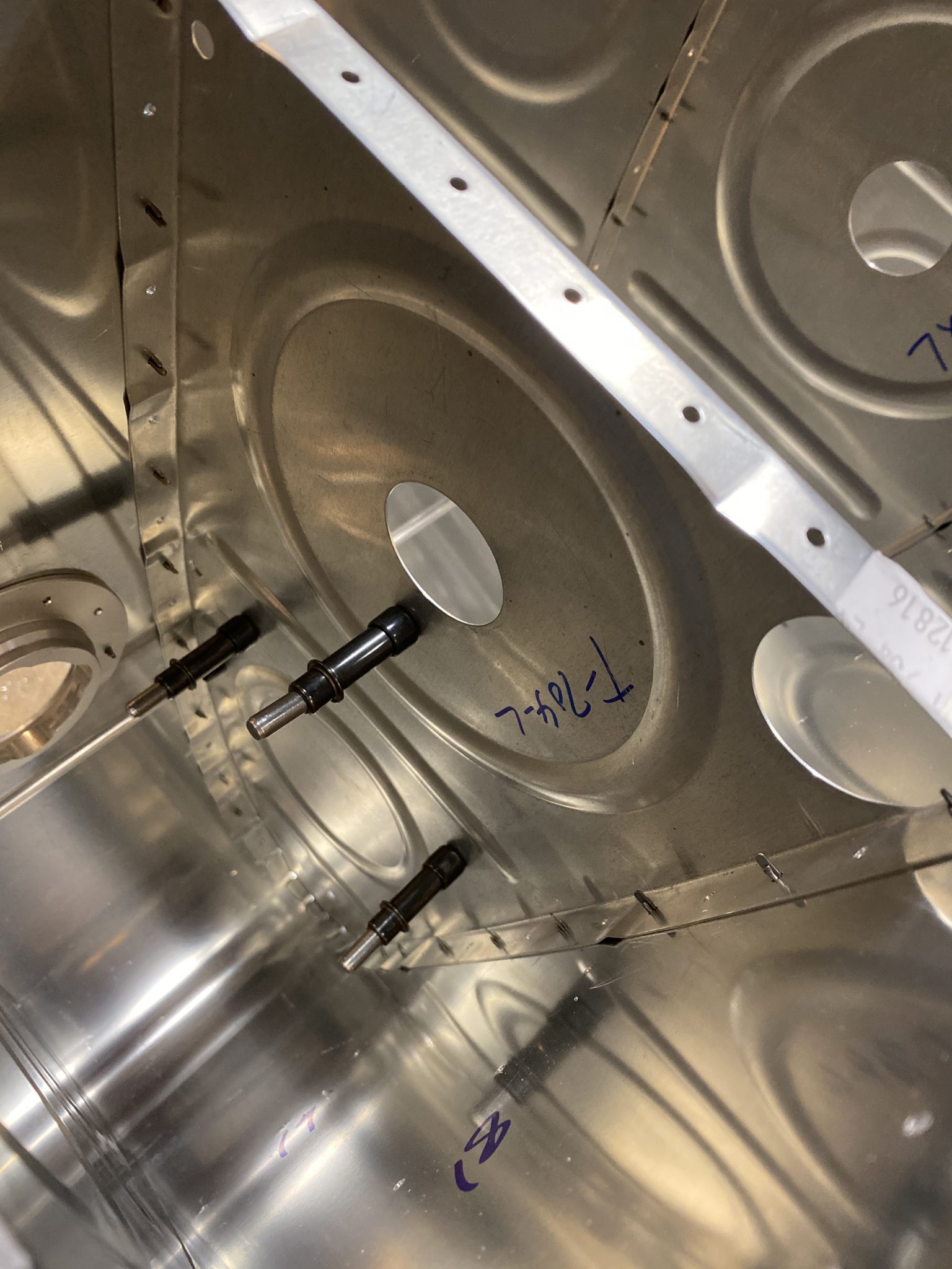
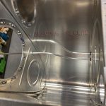
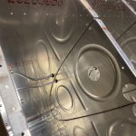
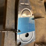
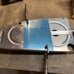
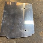
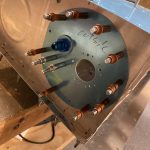
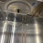
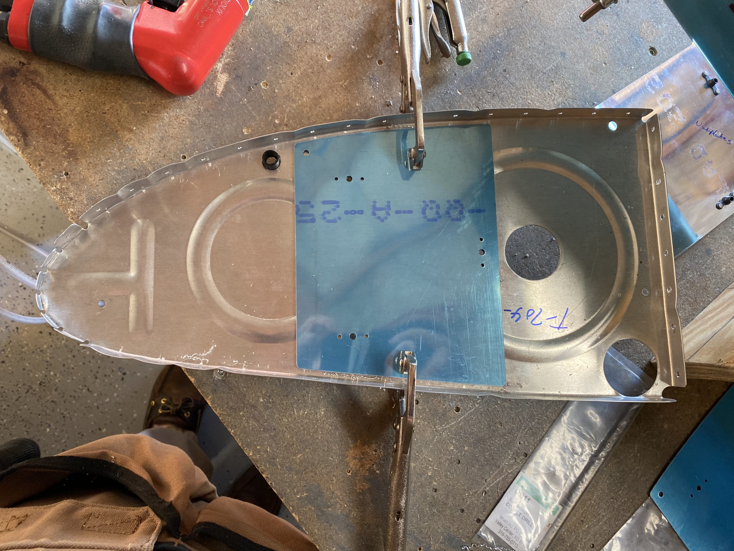
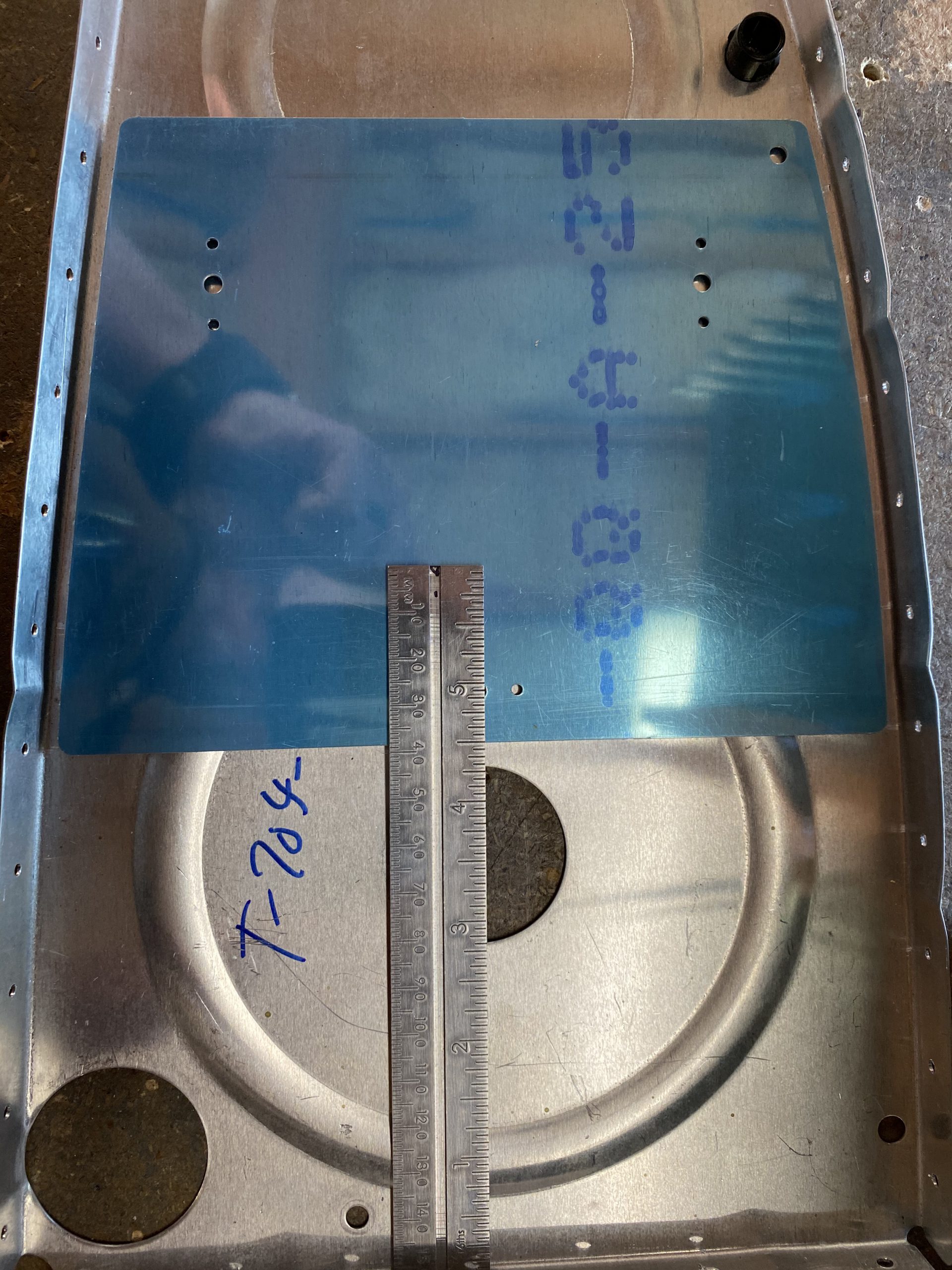
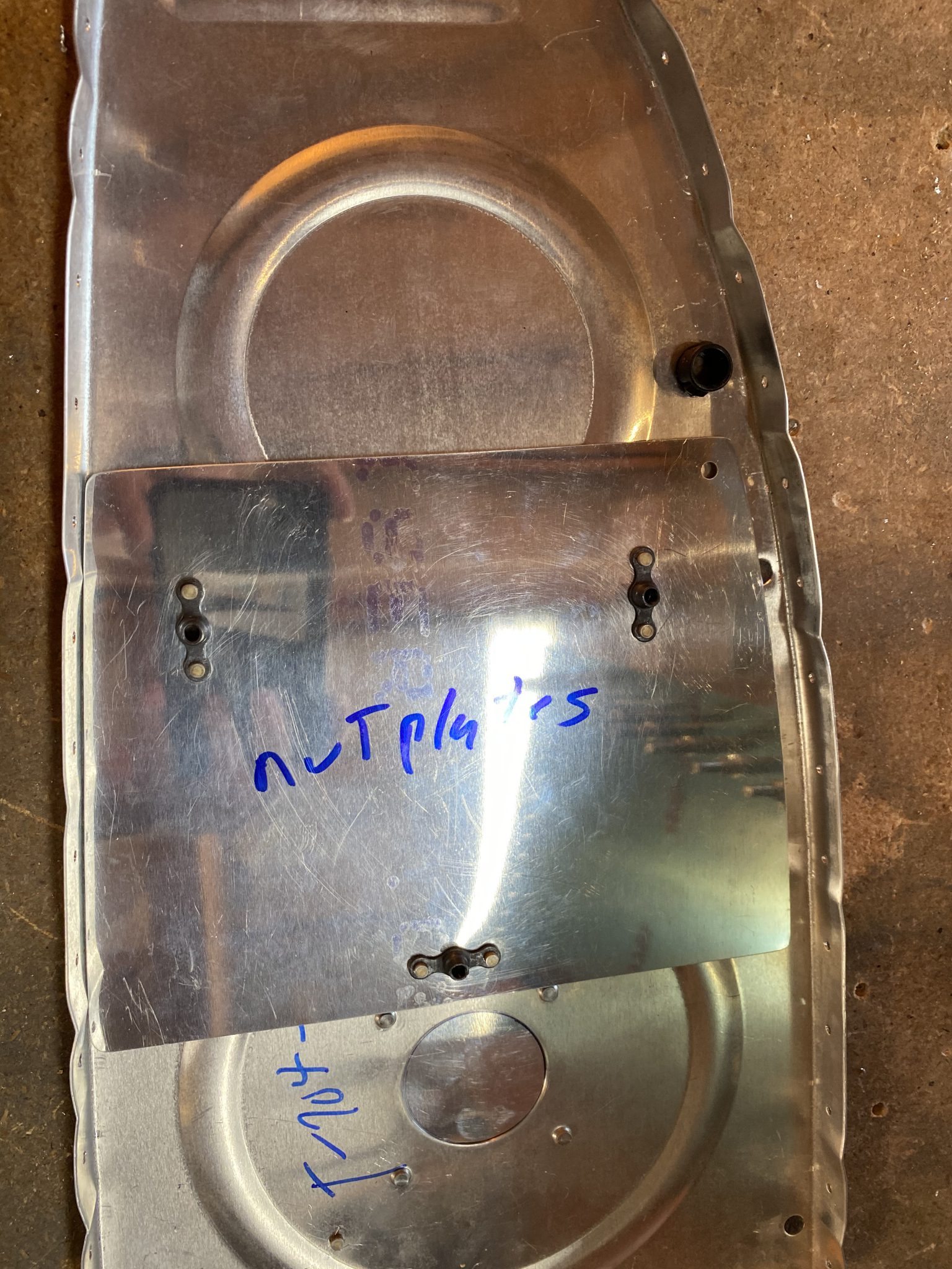
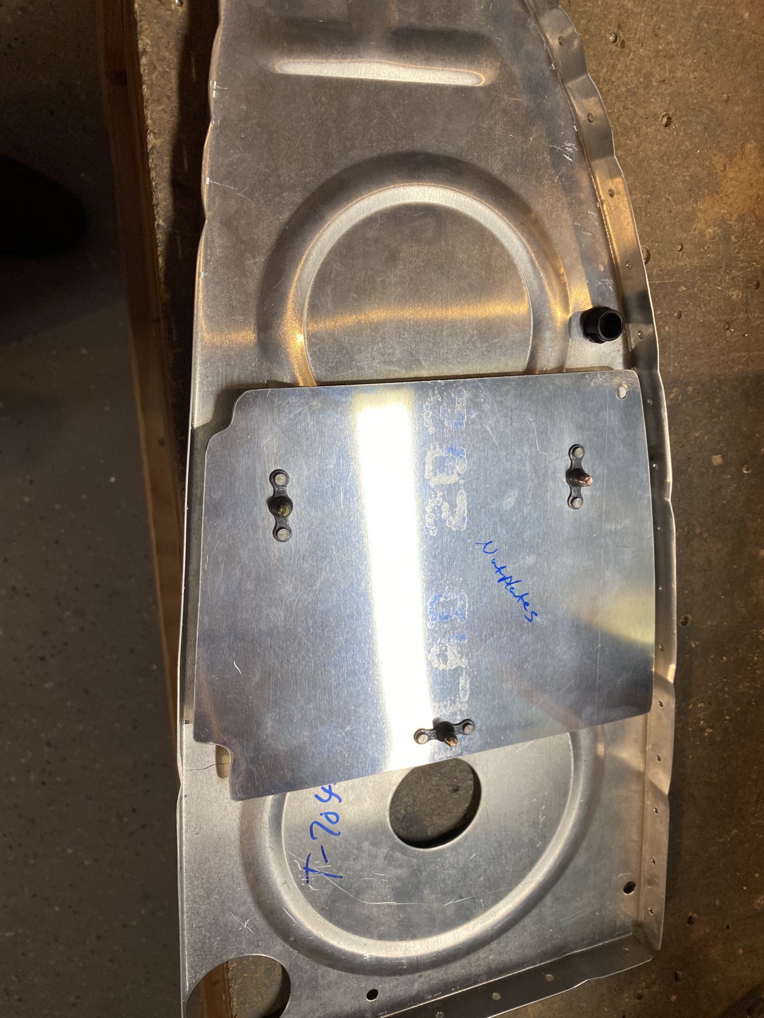
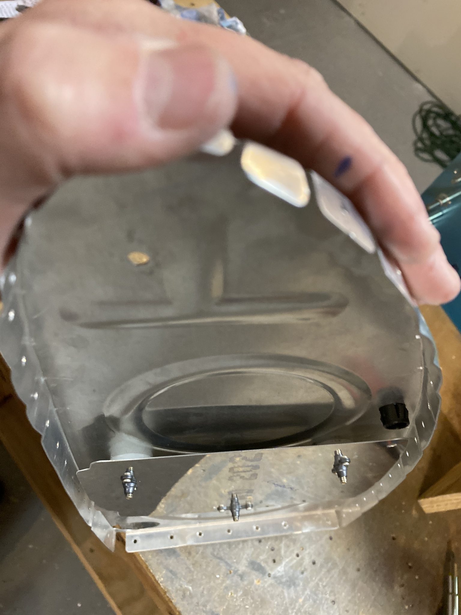
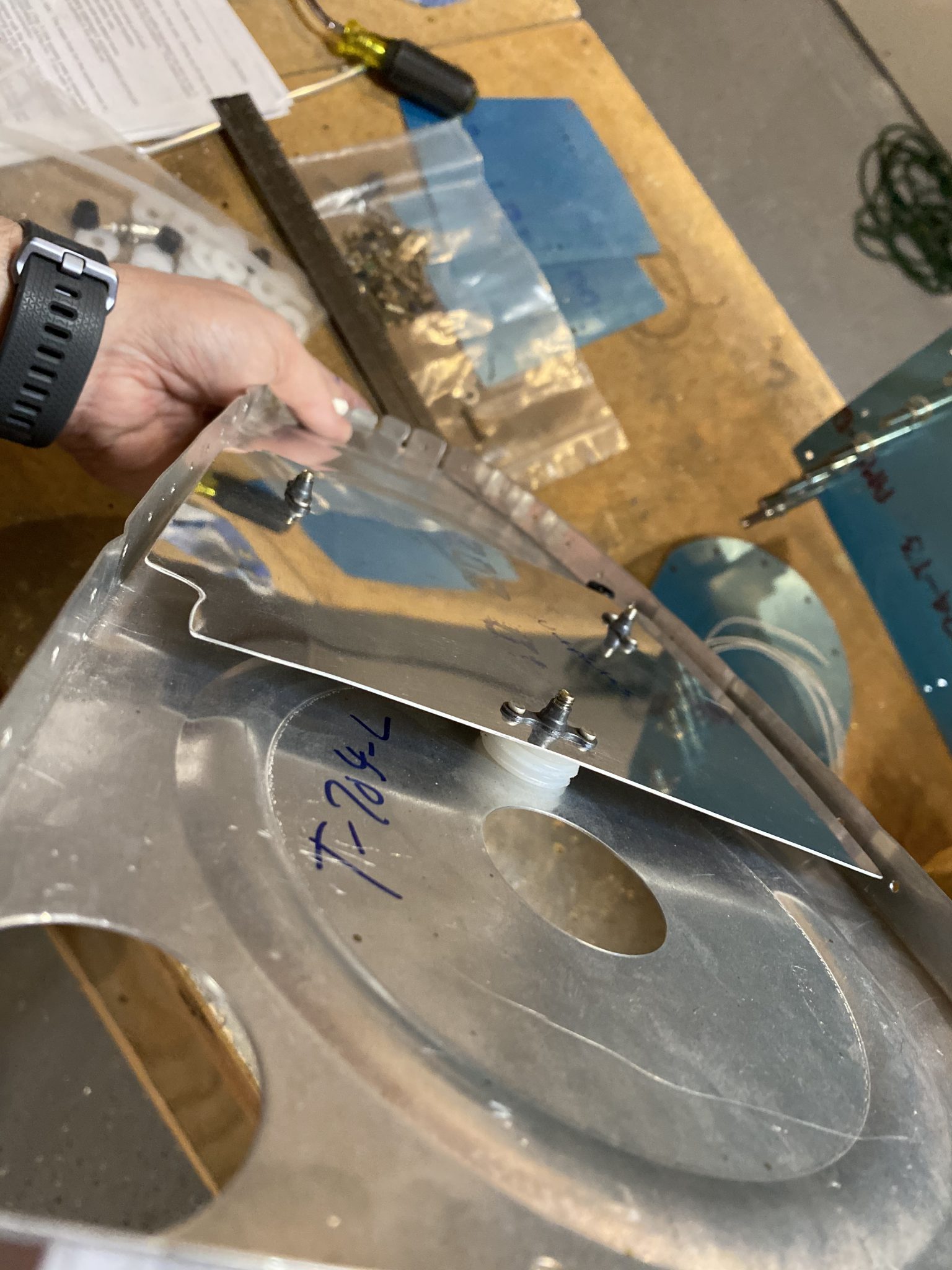
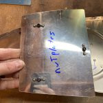
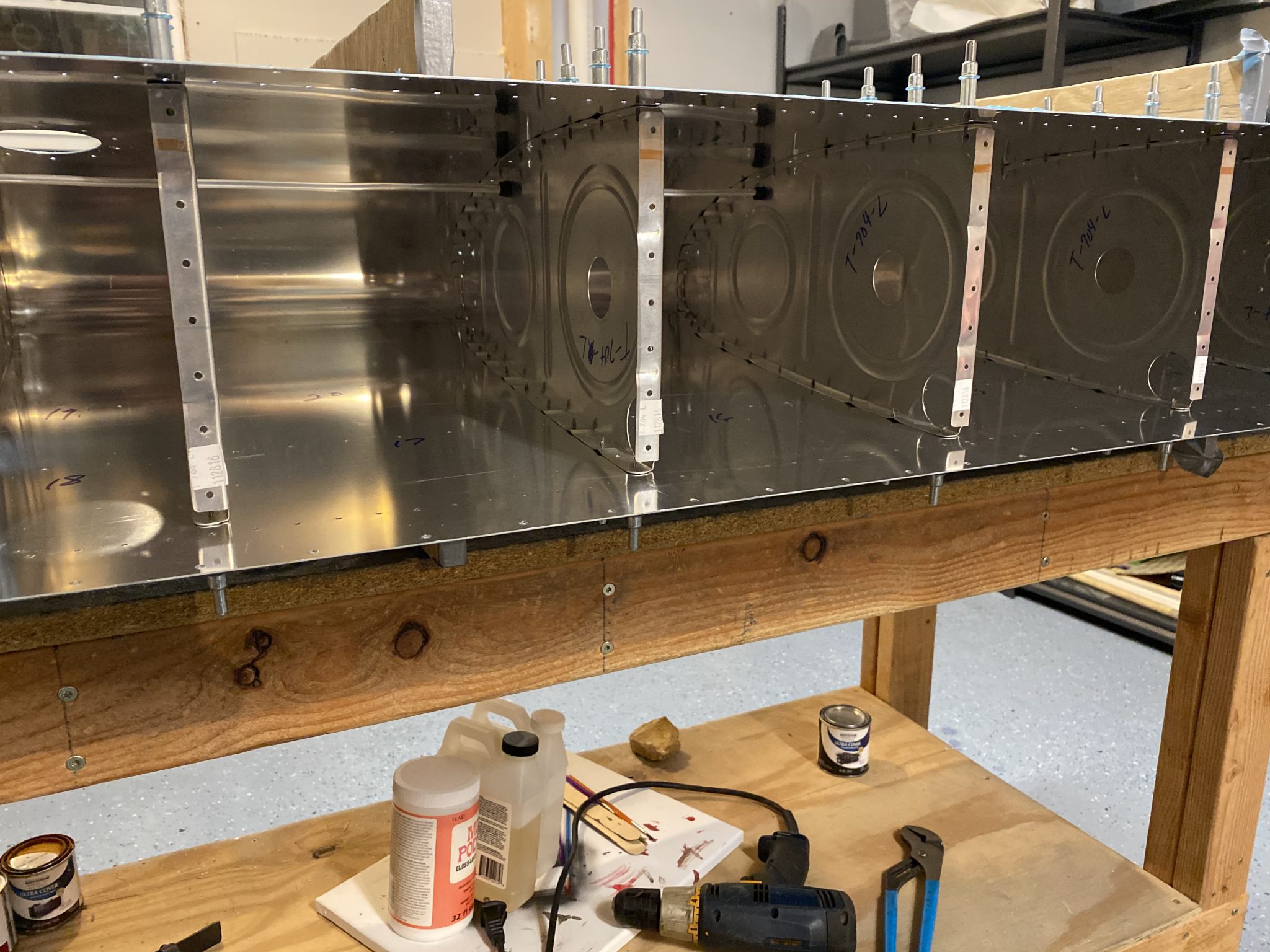
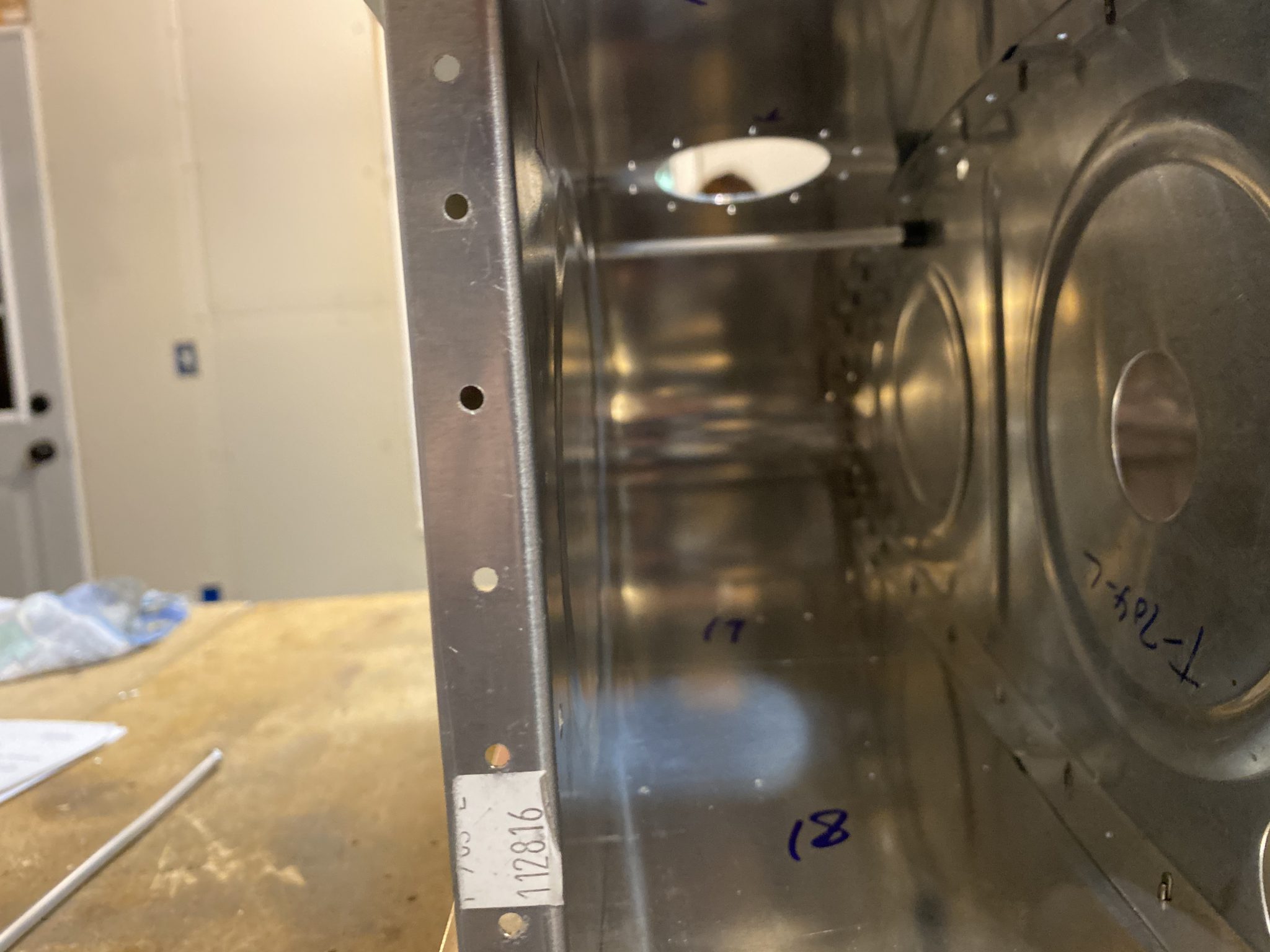
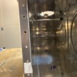
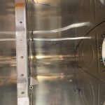
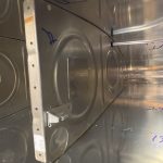
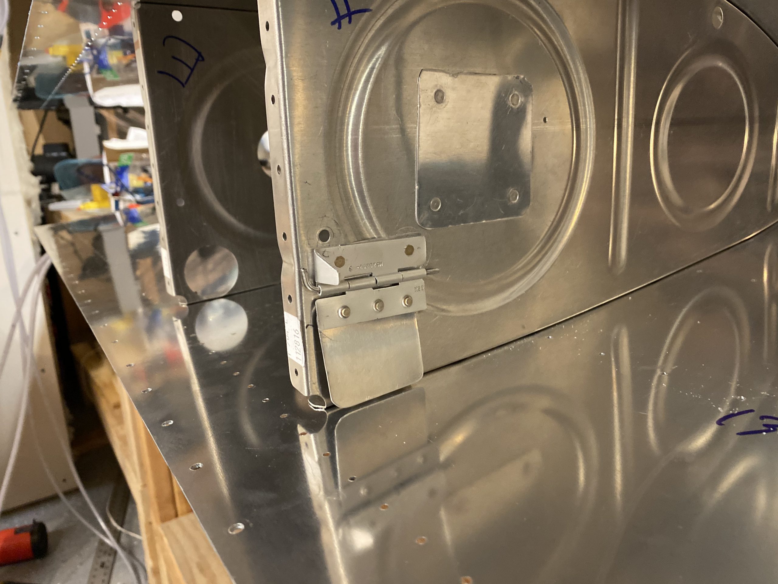
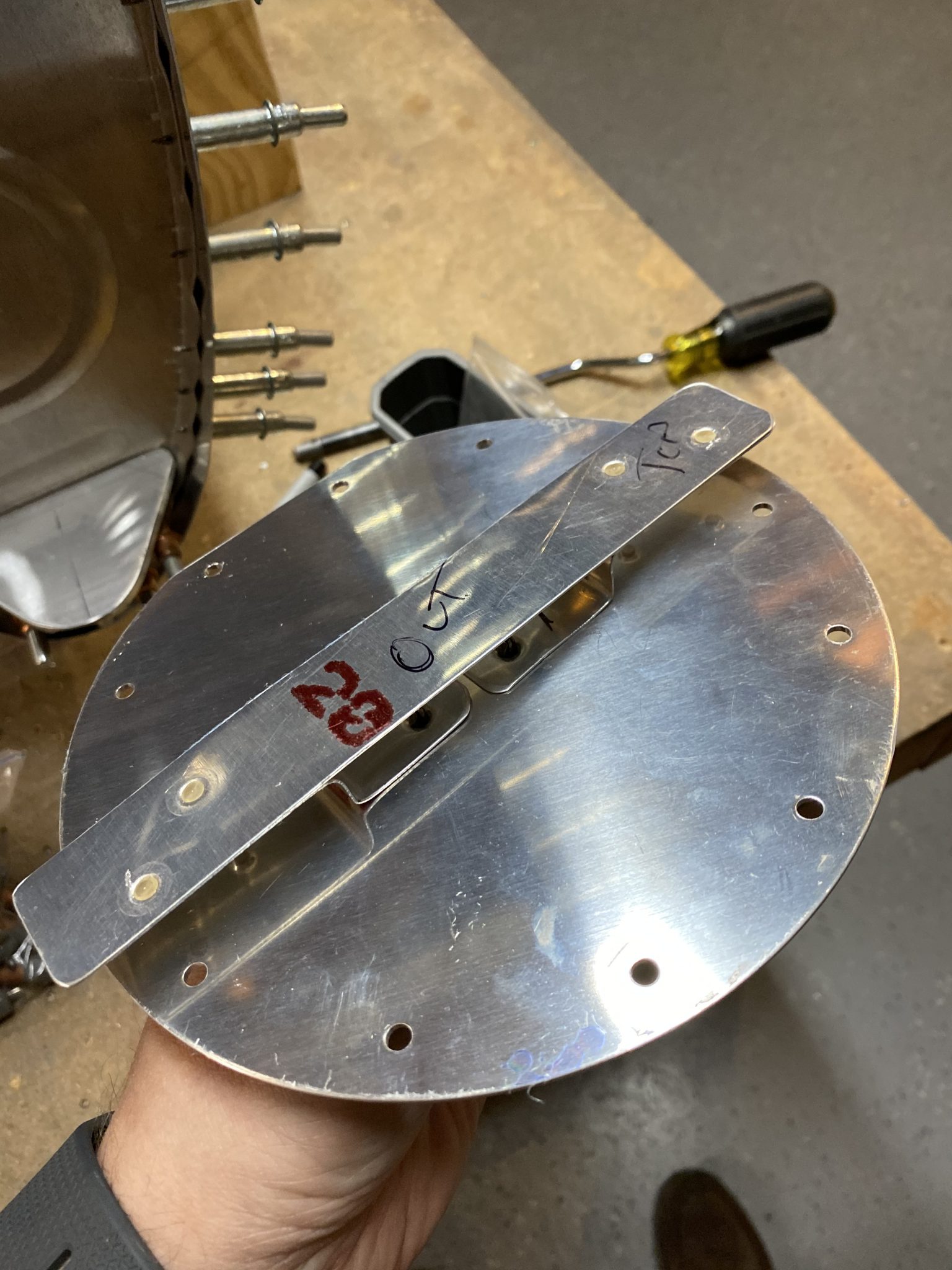
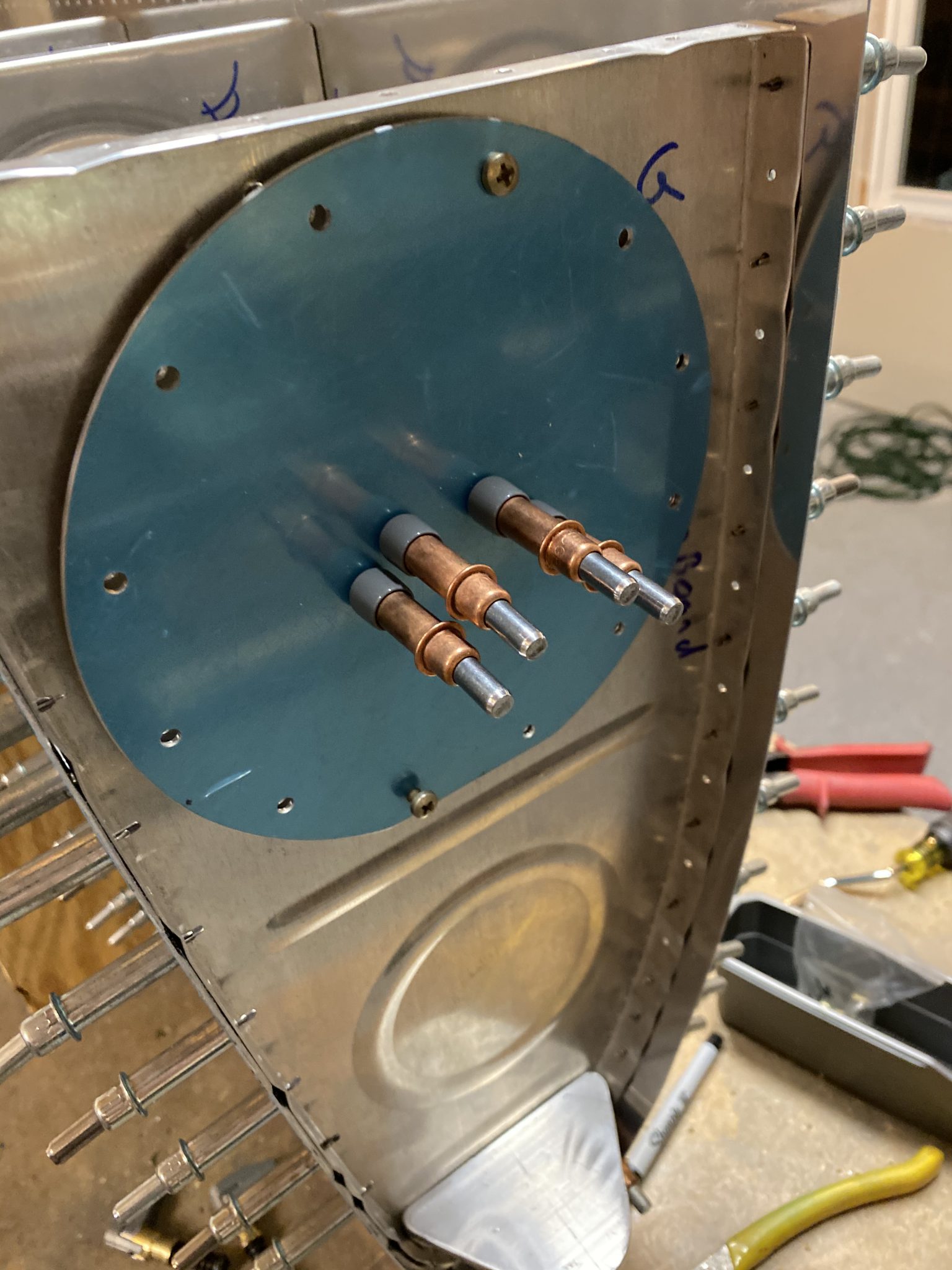
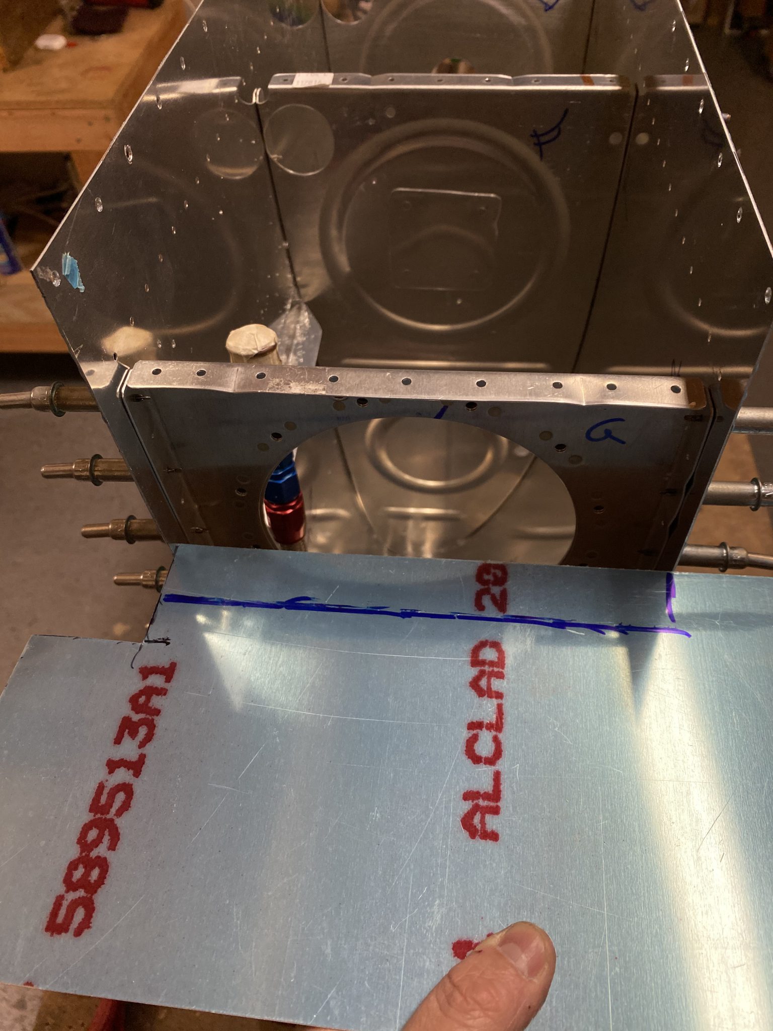
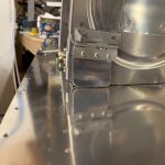
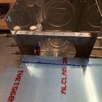
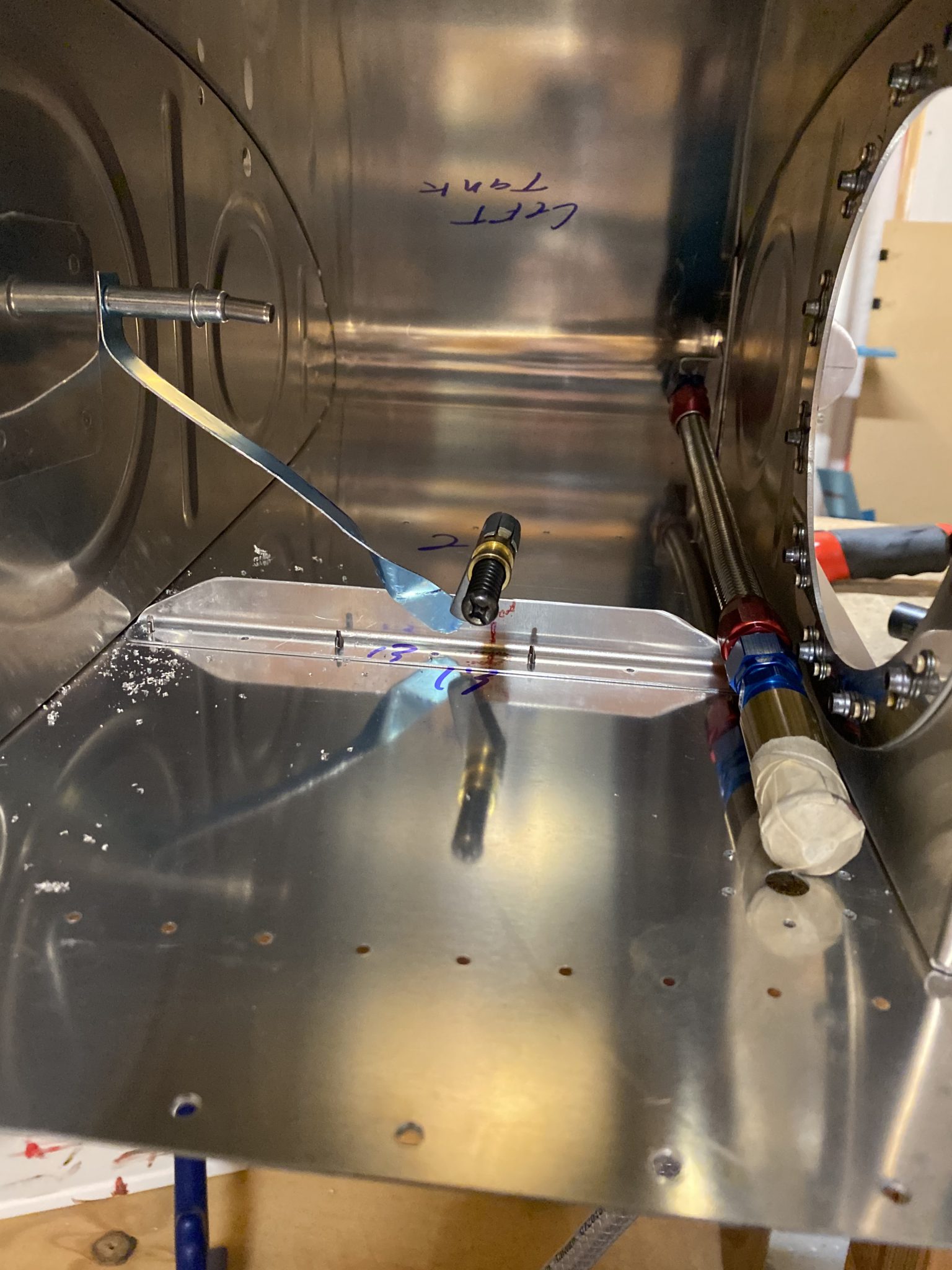
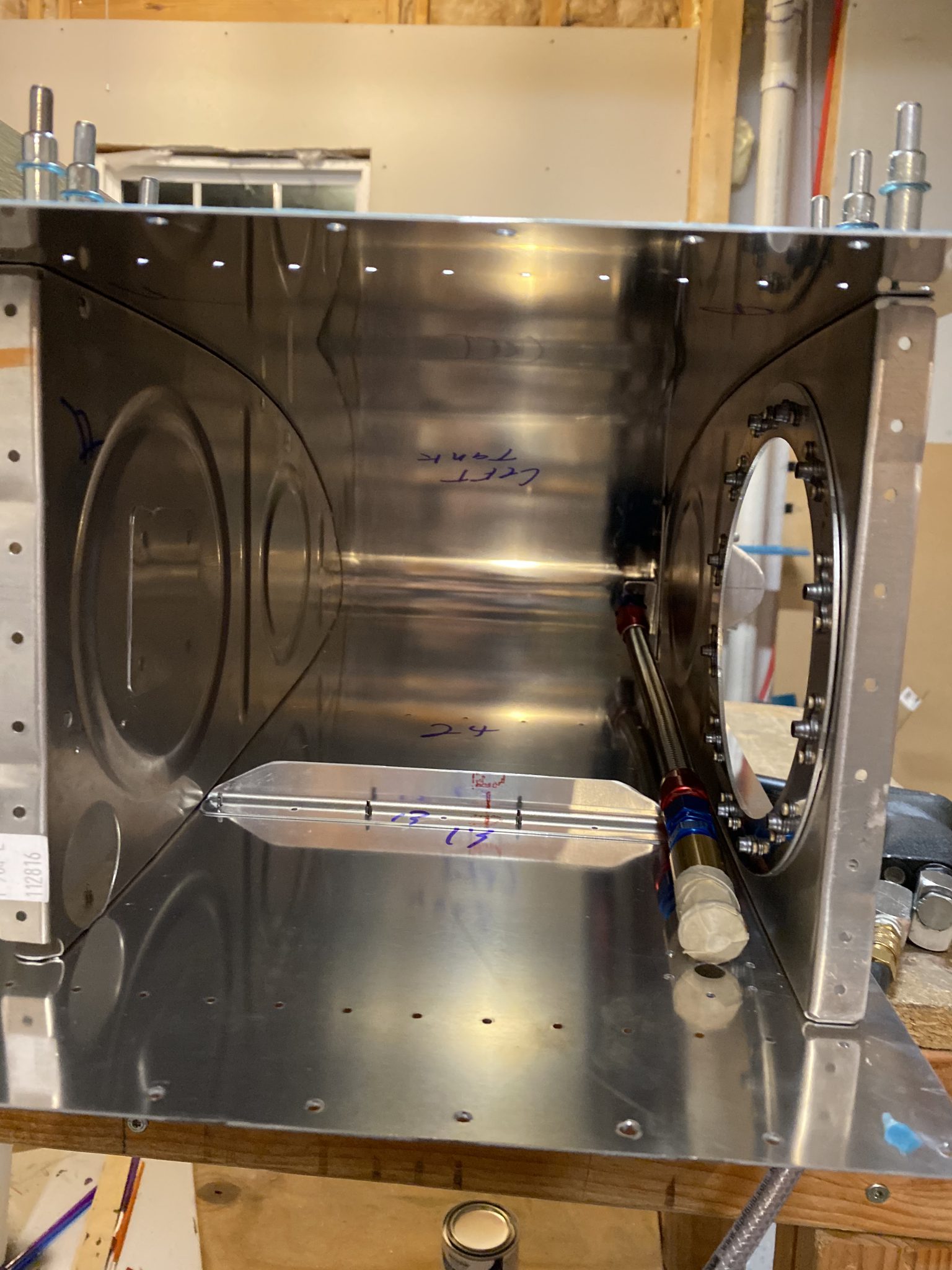
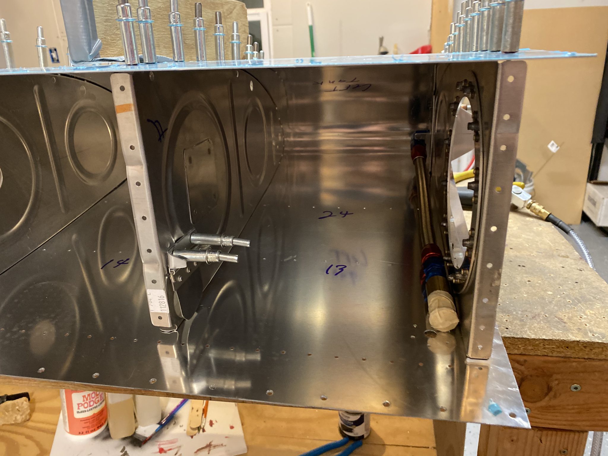
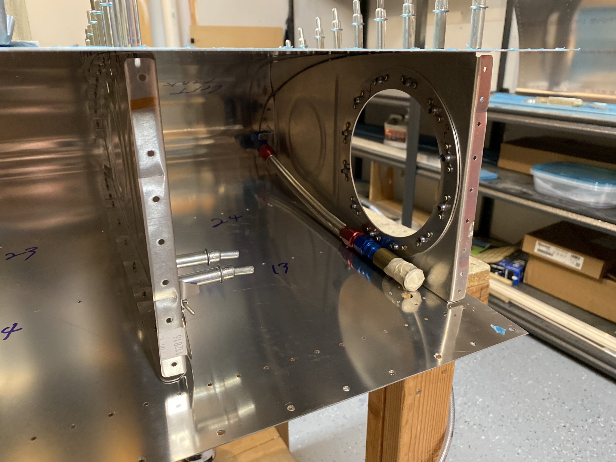
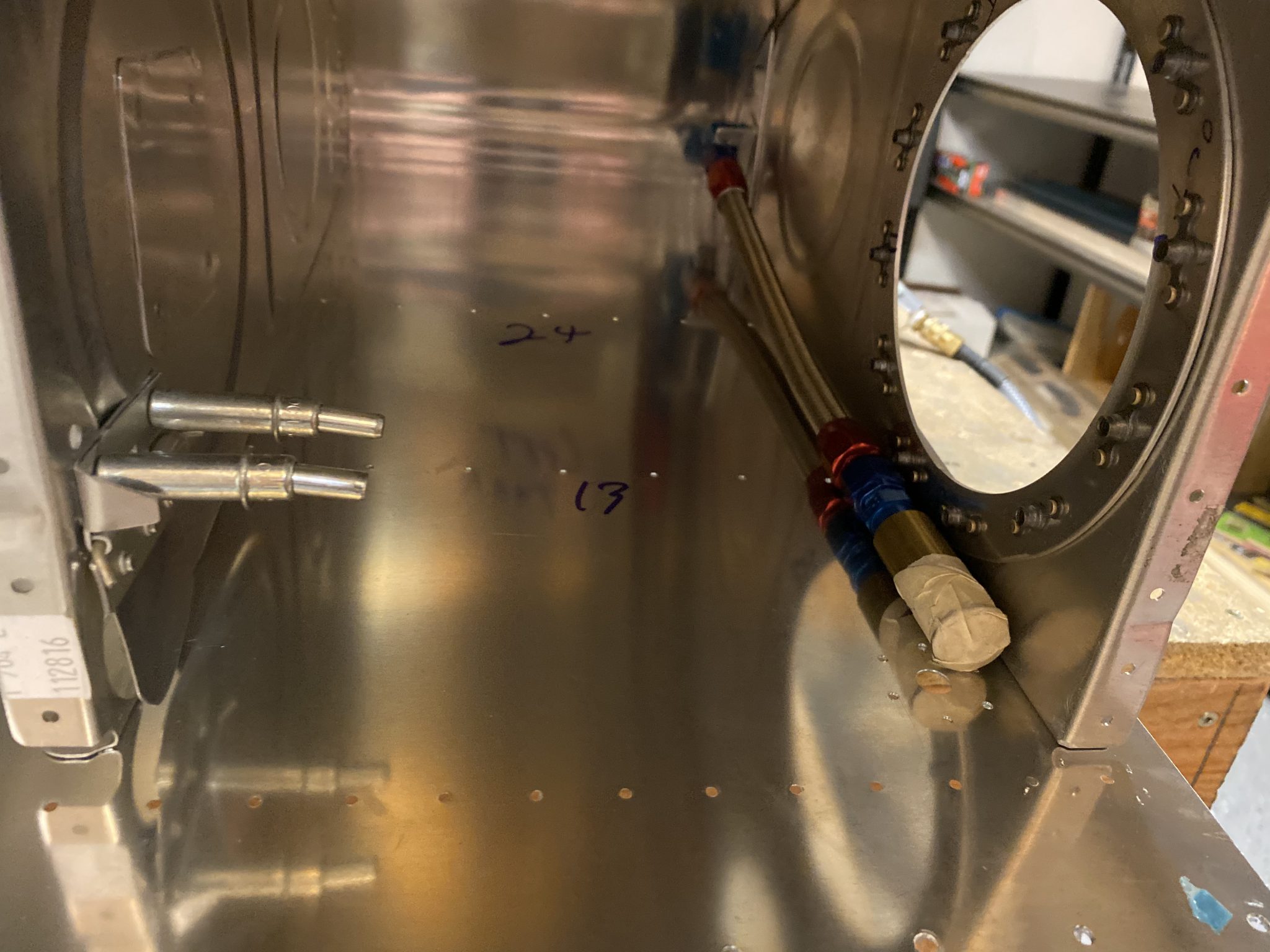
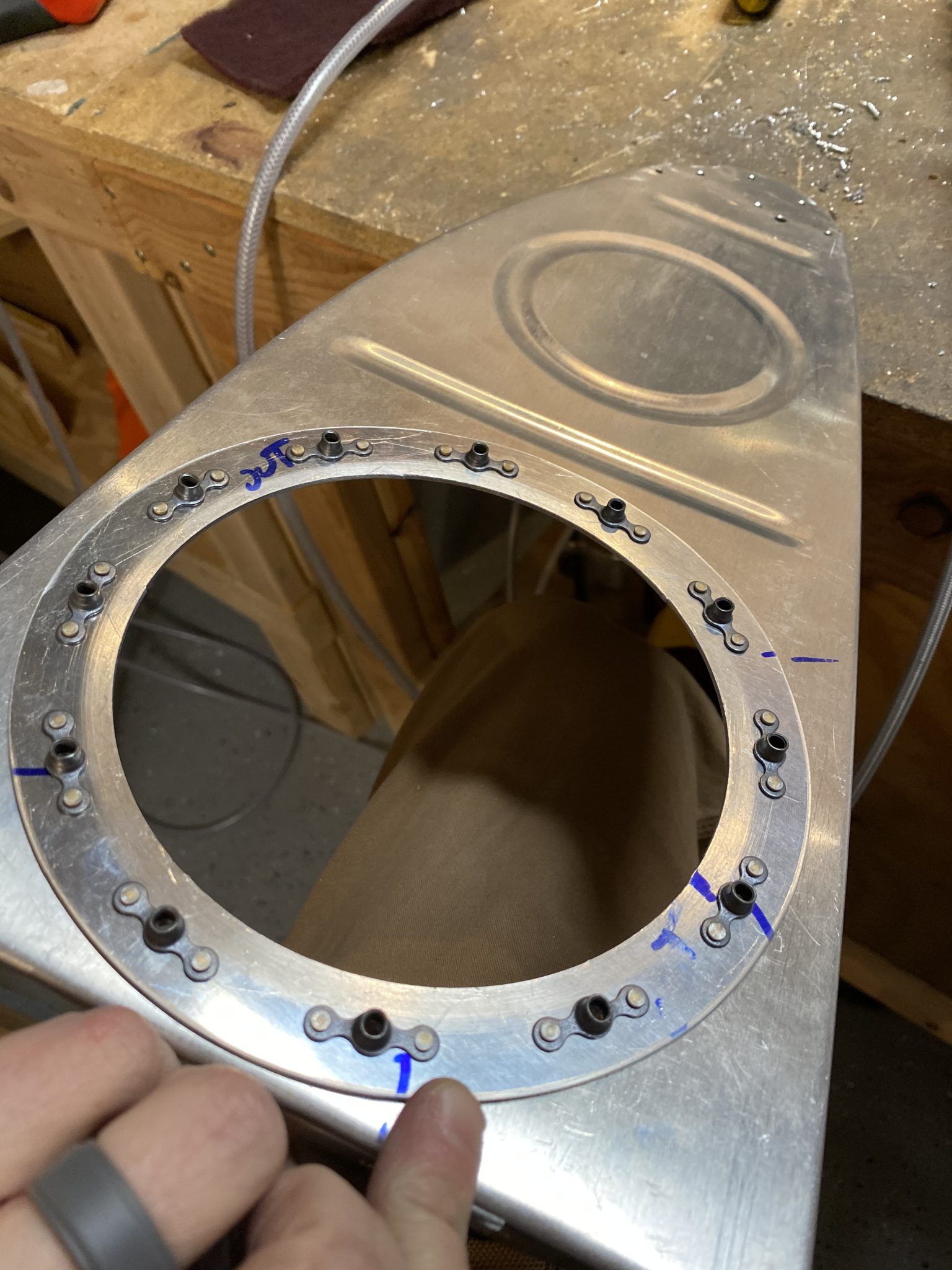
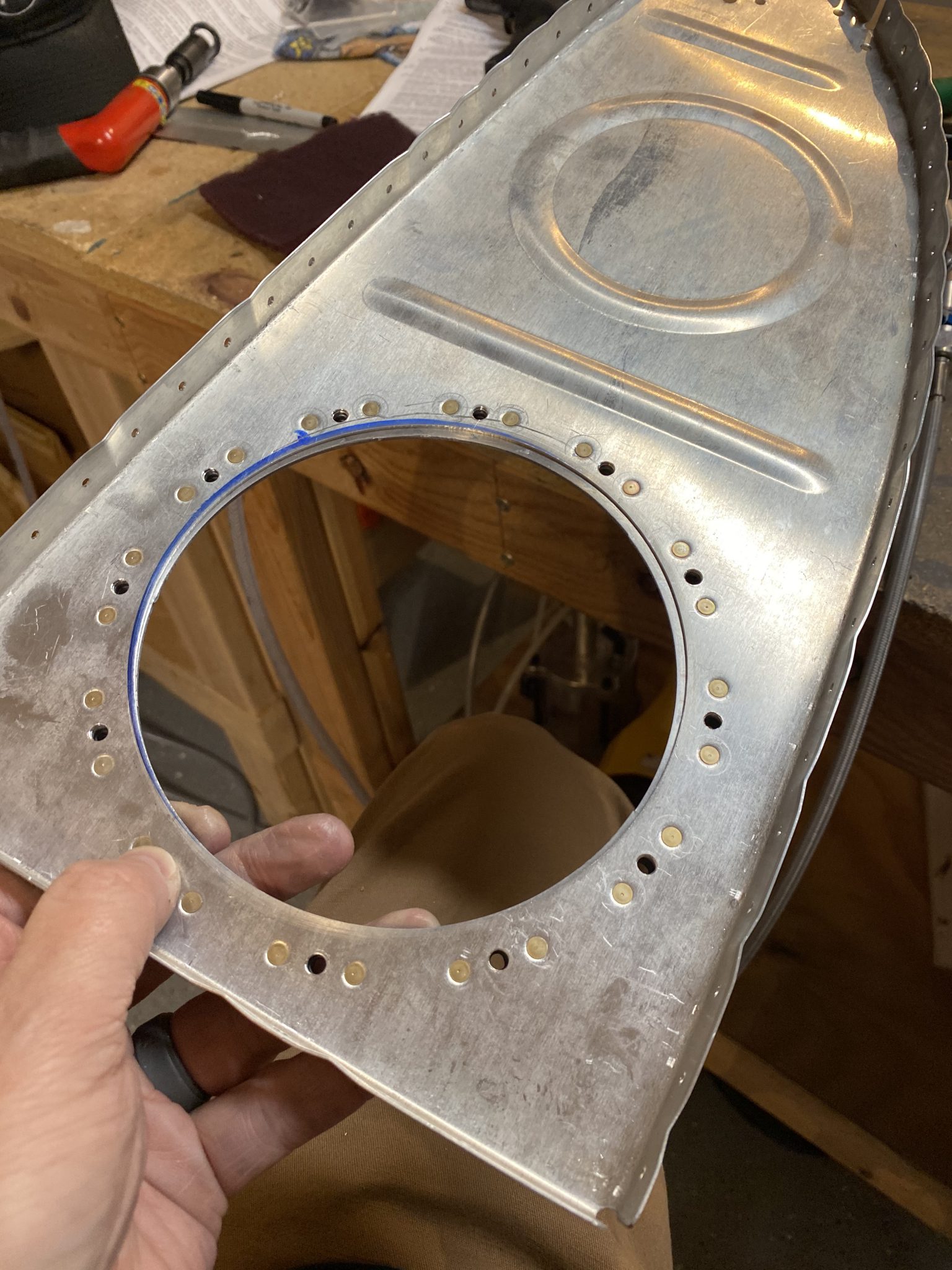
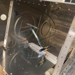
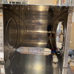
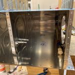
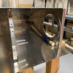
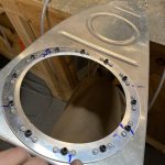
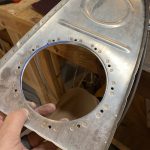
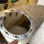
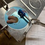
I decided to block off the hole in the inner rib. Some builders do this, and some don’t. For me, I want that inner fuel bay to be sealed off so I can do sustained inverted or knife edge flying. If I left this hole unblocked, that would allow fuel to drain back to the outboard side of the tanks, away from the flop tube in some flight attitudes. In addition, it looks like the flop tube may actually get caught in the hole in some situations. So, closing it up is pretty simple: a 4.5″ square of 0.020″ alcald and a few rivets. I measured and cut some of my scrap alclad, and marked up the rivet holes with edge distance in mind. Then I drilled the holes in the plate.

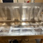
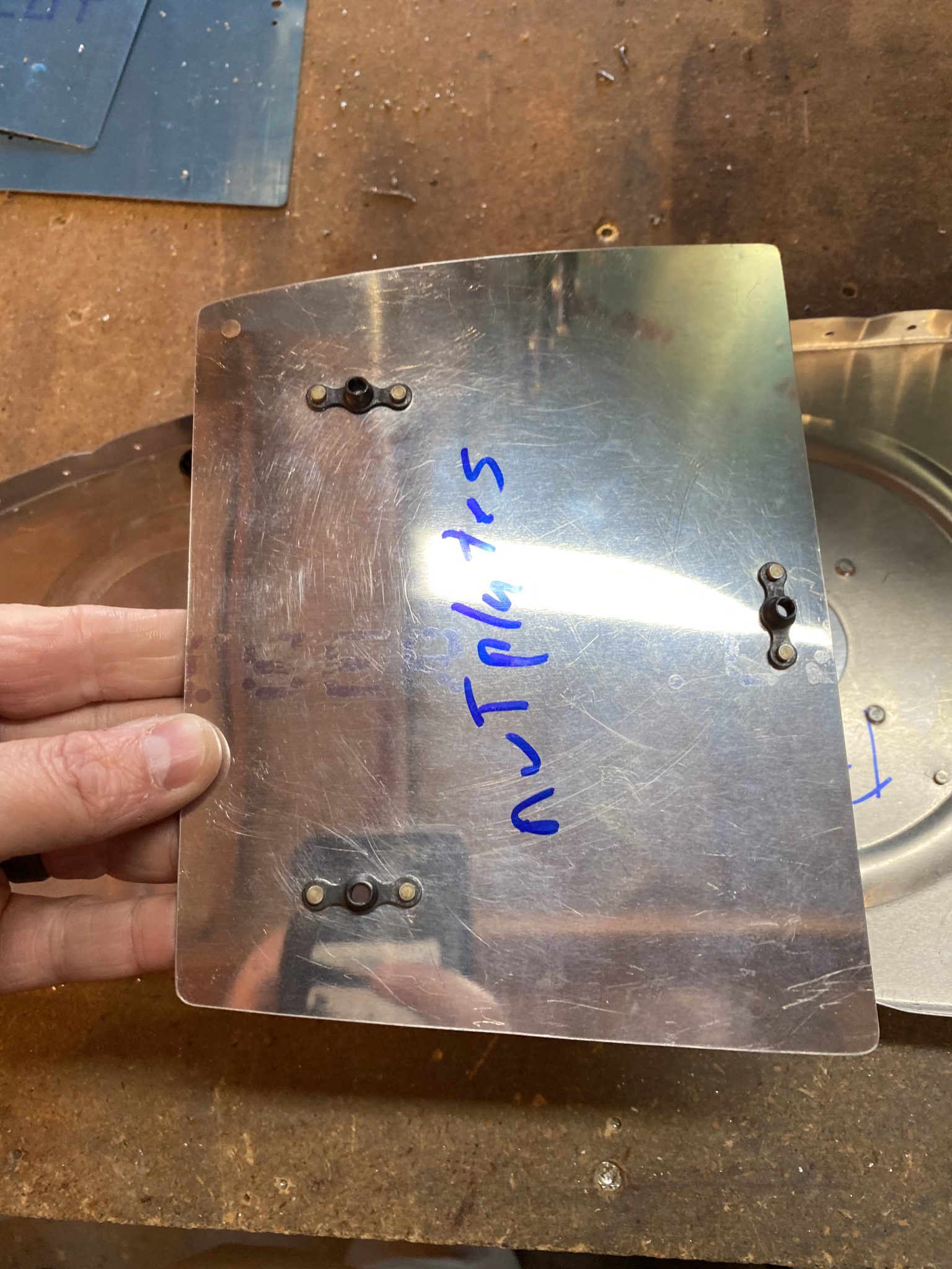
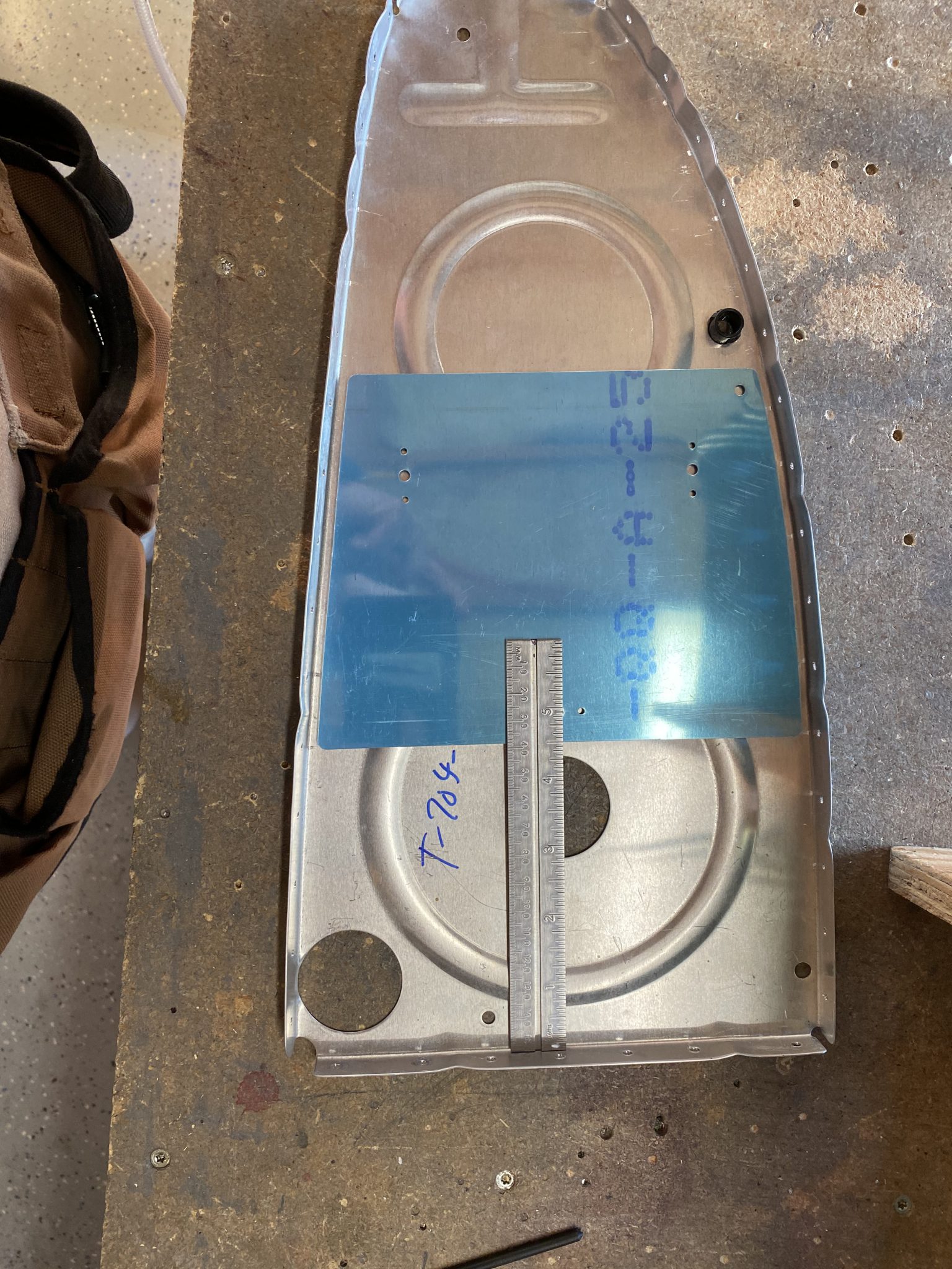
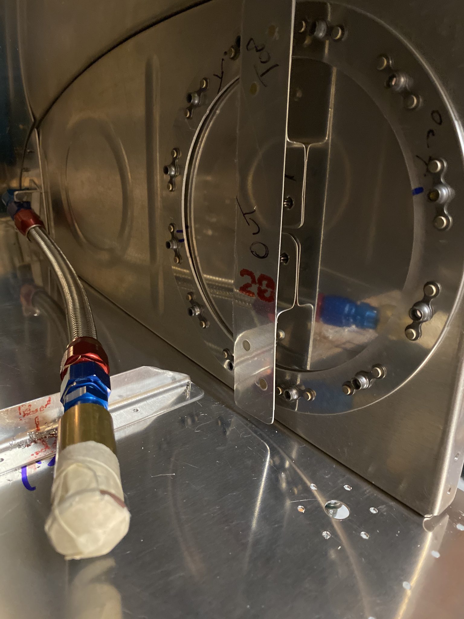
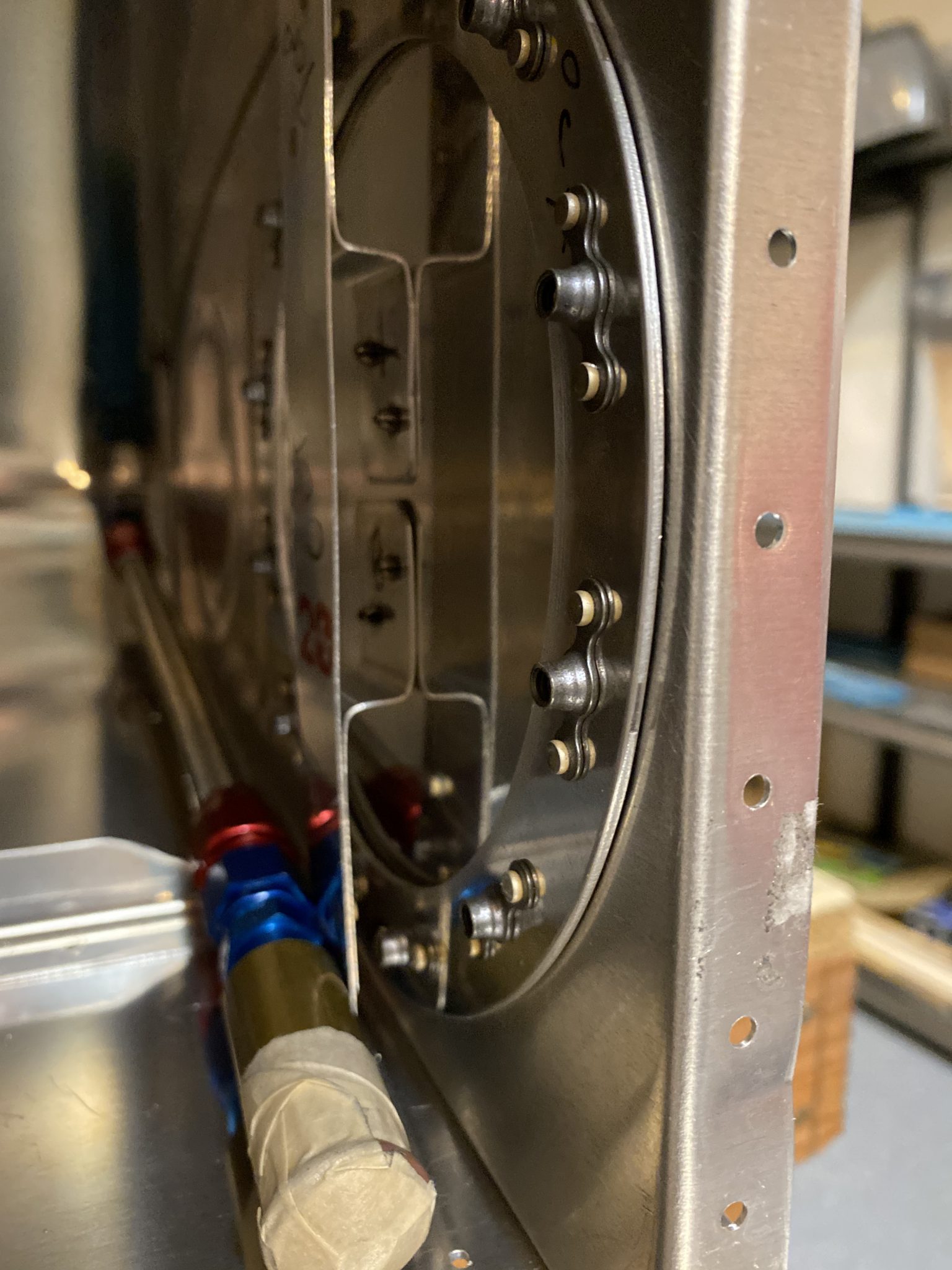
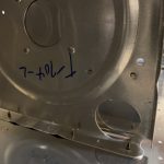
Once the holes were drilled and deburred, I went ahead and dimpled the blocking plate as well as the ribs so I could use flush rivets on the inner side of the fuel bay, giving even more less things the flop tube could catch on. I used some AN426AD3-3.5 rivets to attach this blocker plate to the rib, making a nice flush surface for the flop tube to rub against, while at the same time, blocking any fuel from leaving my inner fuel bay when flying knife edge, with the left wing low, and the trap door flapper closed.

I’m really pleased with how this came out. I spent a good 4 hours or more just fabricating and fitting these parts. I still need to fab and install the anti-hangup straps that go in the tank to keep the flop tube from hanging on certain bits. But, I was out of steam for the day, and figured that would be a good “Part Two” for my next session.
Google Photos Link: https://photos.app.goo.gl/iTp5eMERkYinN43e7
Hours Worked: 4.25


 IMG_1041
 IMG_1040
 IMG_1039
 IMG_1038
 IMG_1037
 IMG_1036
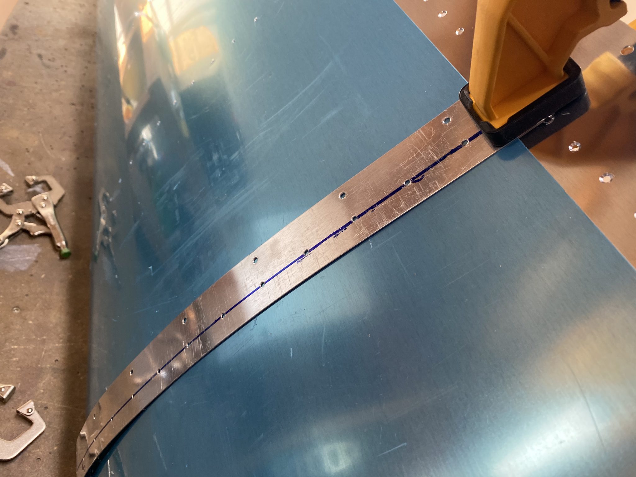 IMG_1035
 IMG_1034
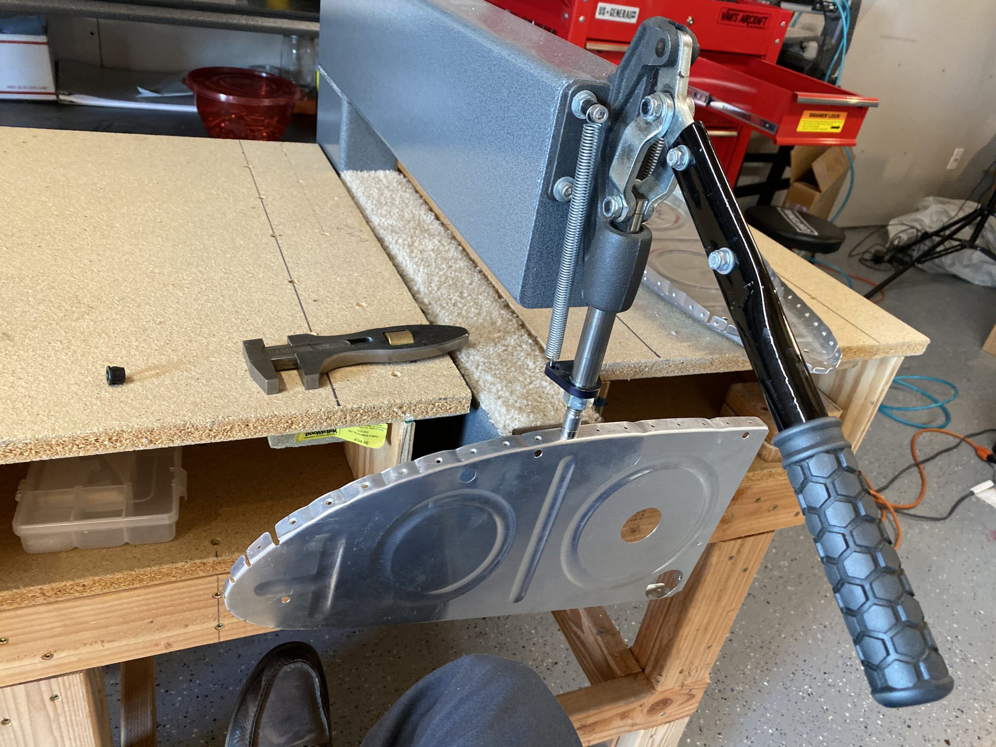 IMG_1033
 IMG_1032
 IMG_1031
 IMG_1030
 IMG_1029
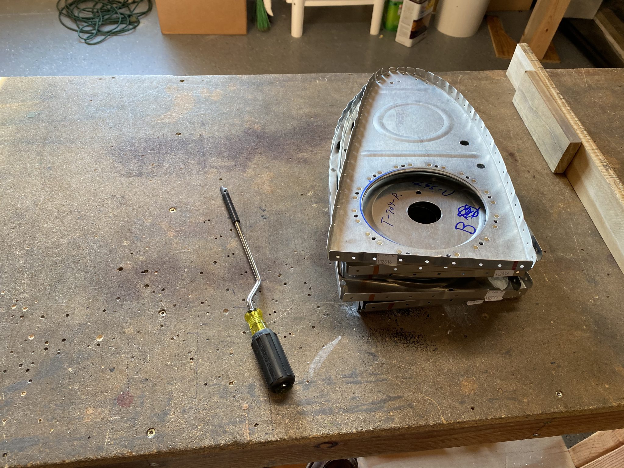 IMG_1028
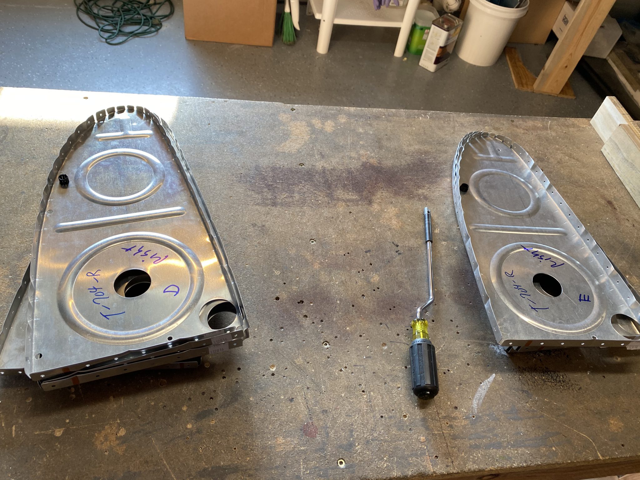 IMG_1027
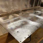
 .
. 


 .
. 


 .
. 


 .
. 


 .
. 


 .
. 


 .
.