


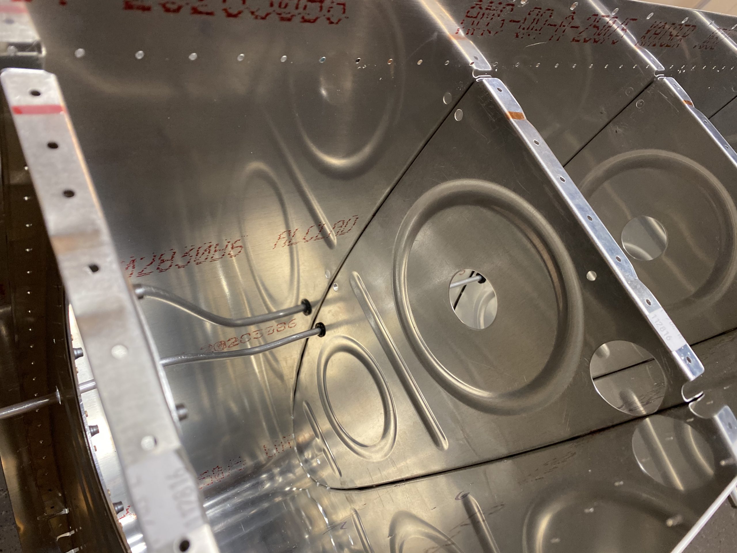
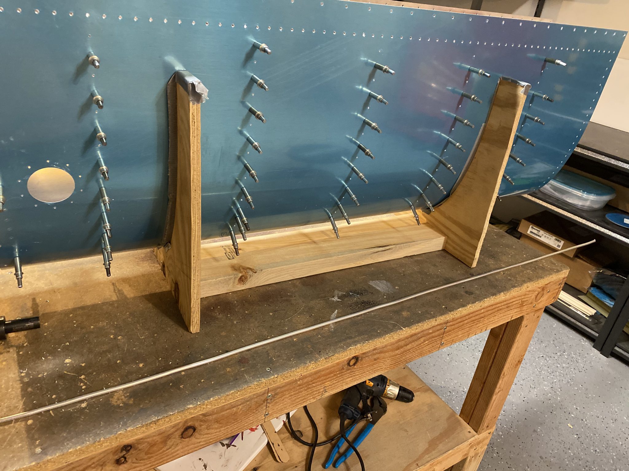
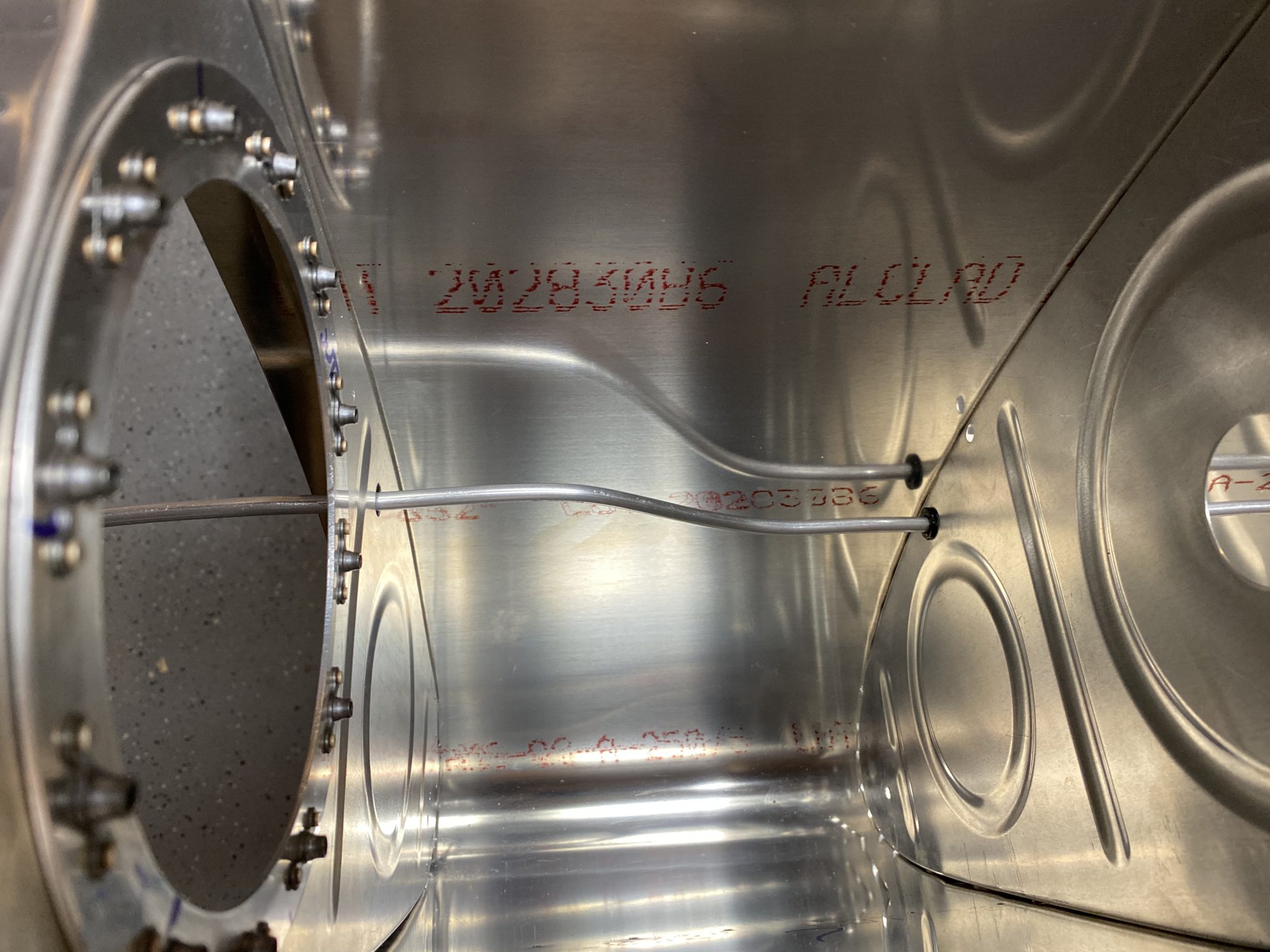
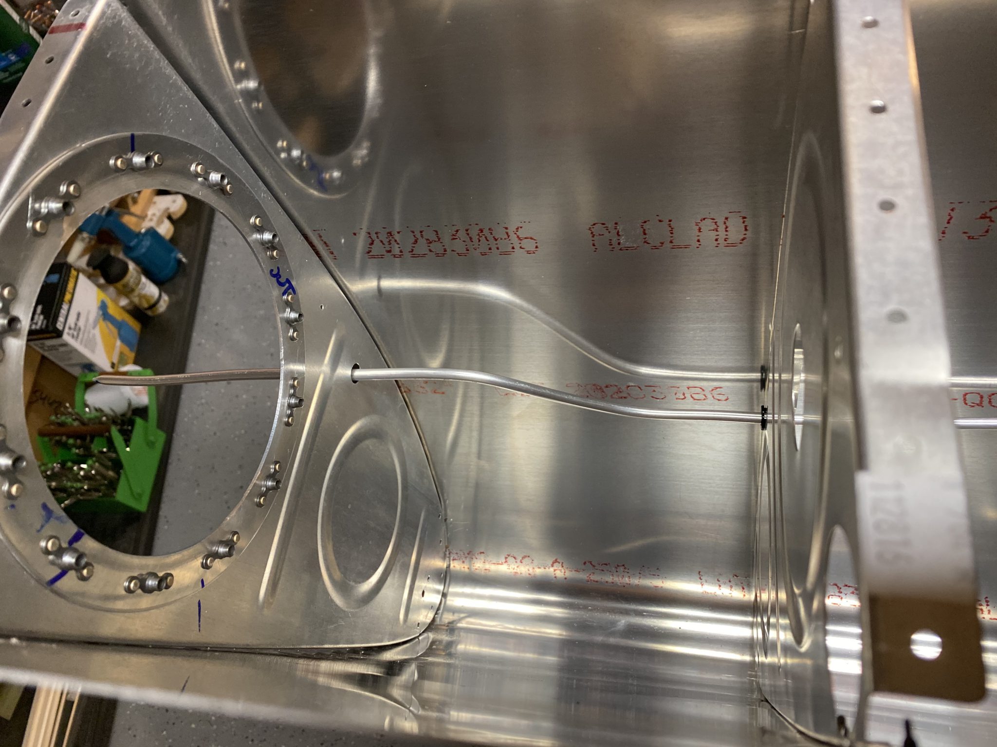
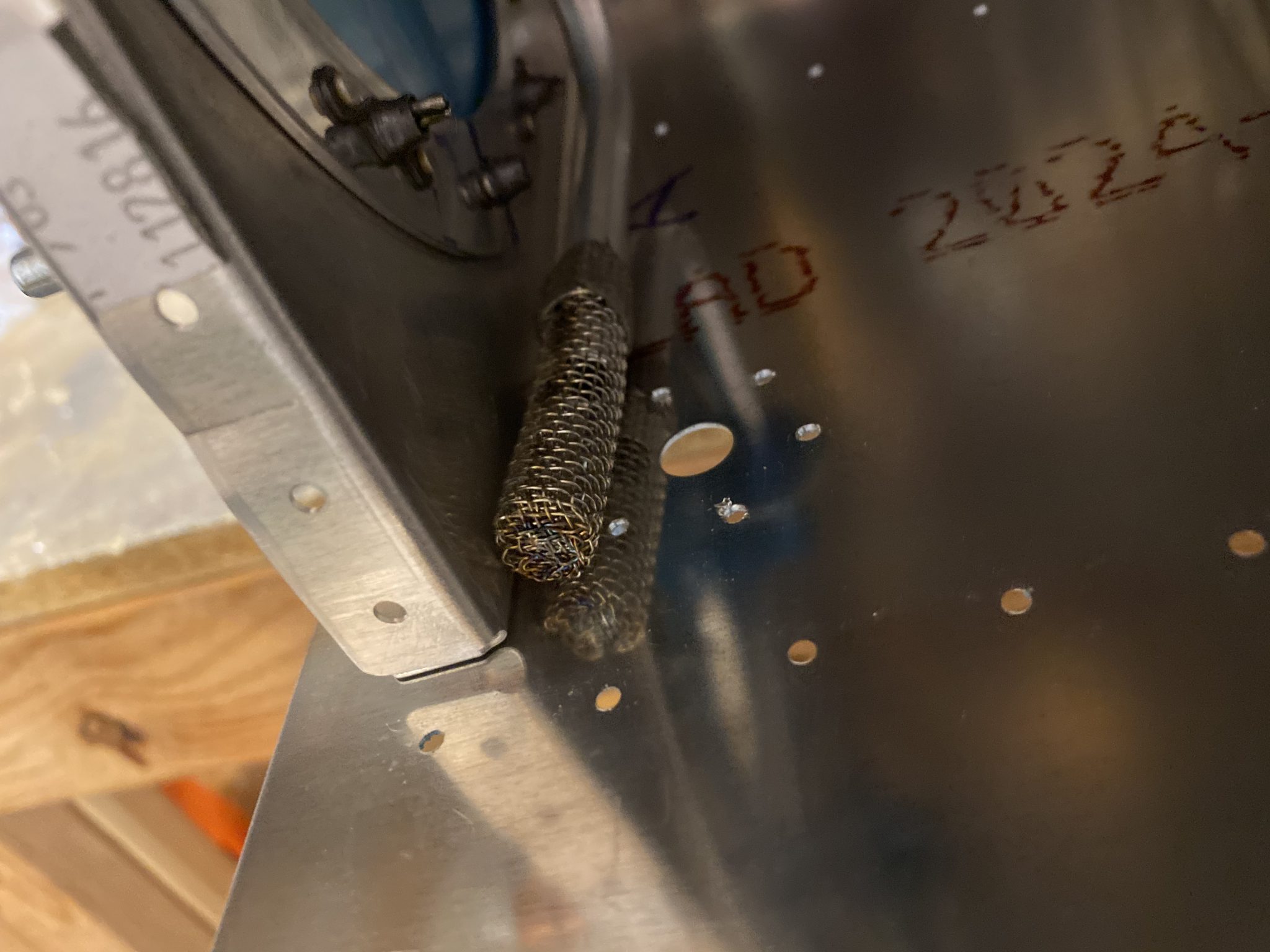
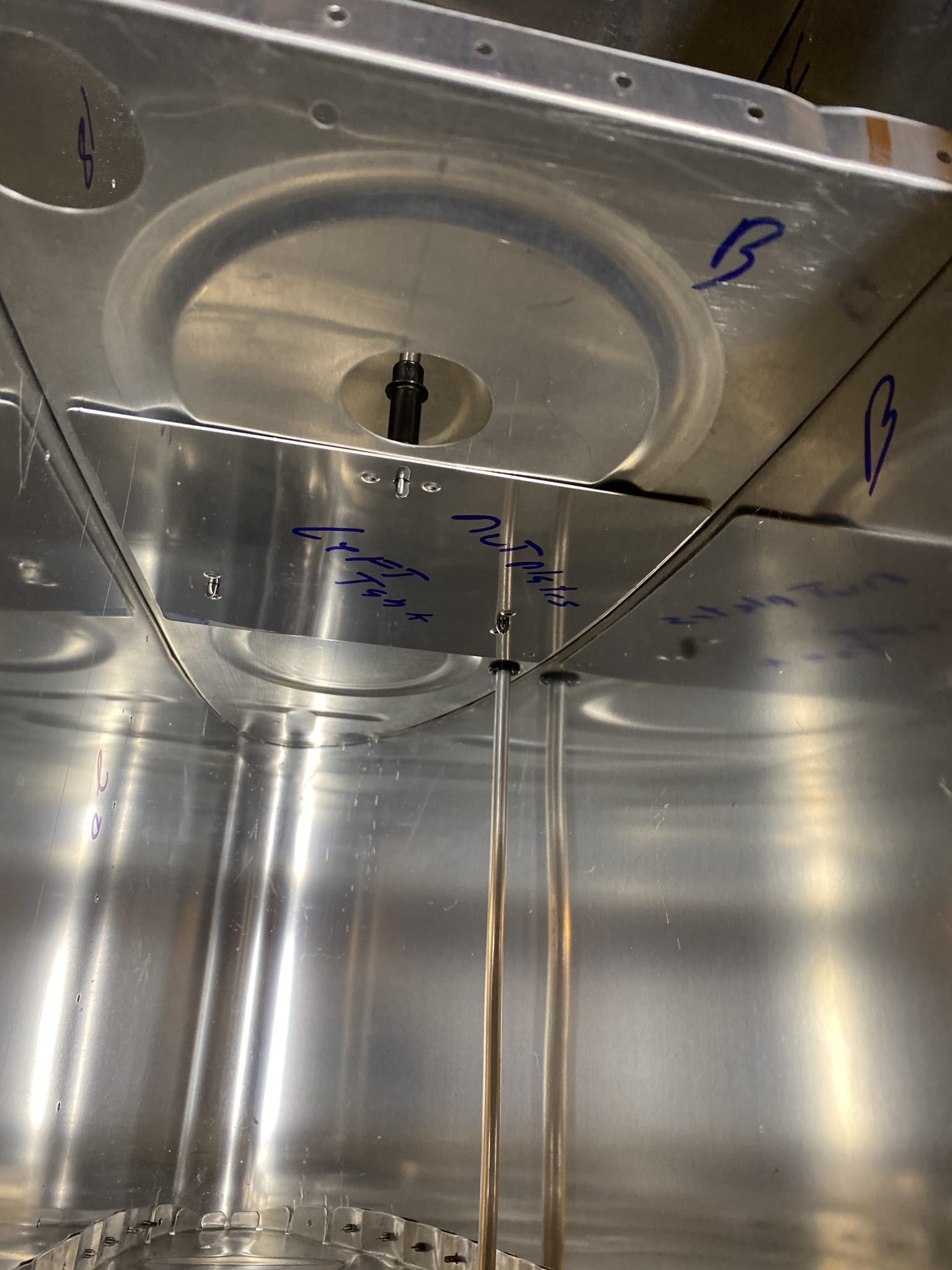
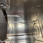
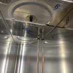
follow site After a short break, I came back down to do some more work on the airplane. Tonight, I was able to get the right tank vent line and the right tank capacitive senders assembled and ready. This time I cleco’d all the ribs and skin for the right tank in the stand so I could get some work done on it. Once I had it all assembled, I grabed the 1/4″ soft aluminum tubing and began unrolling and straightening it to form my tank vent line.

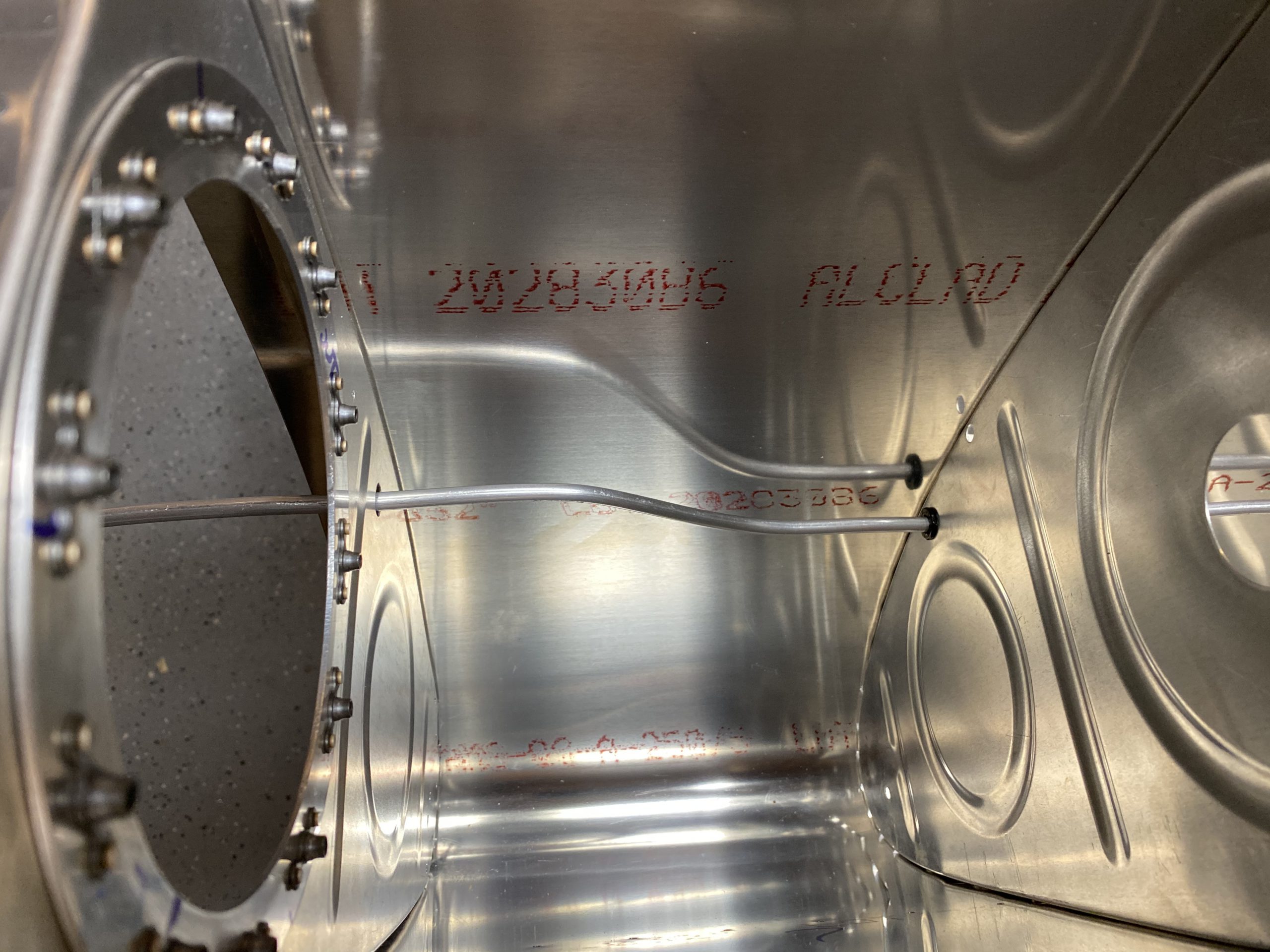
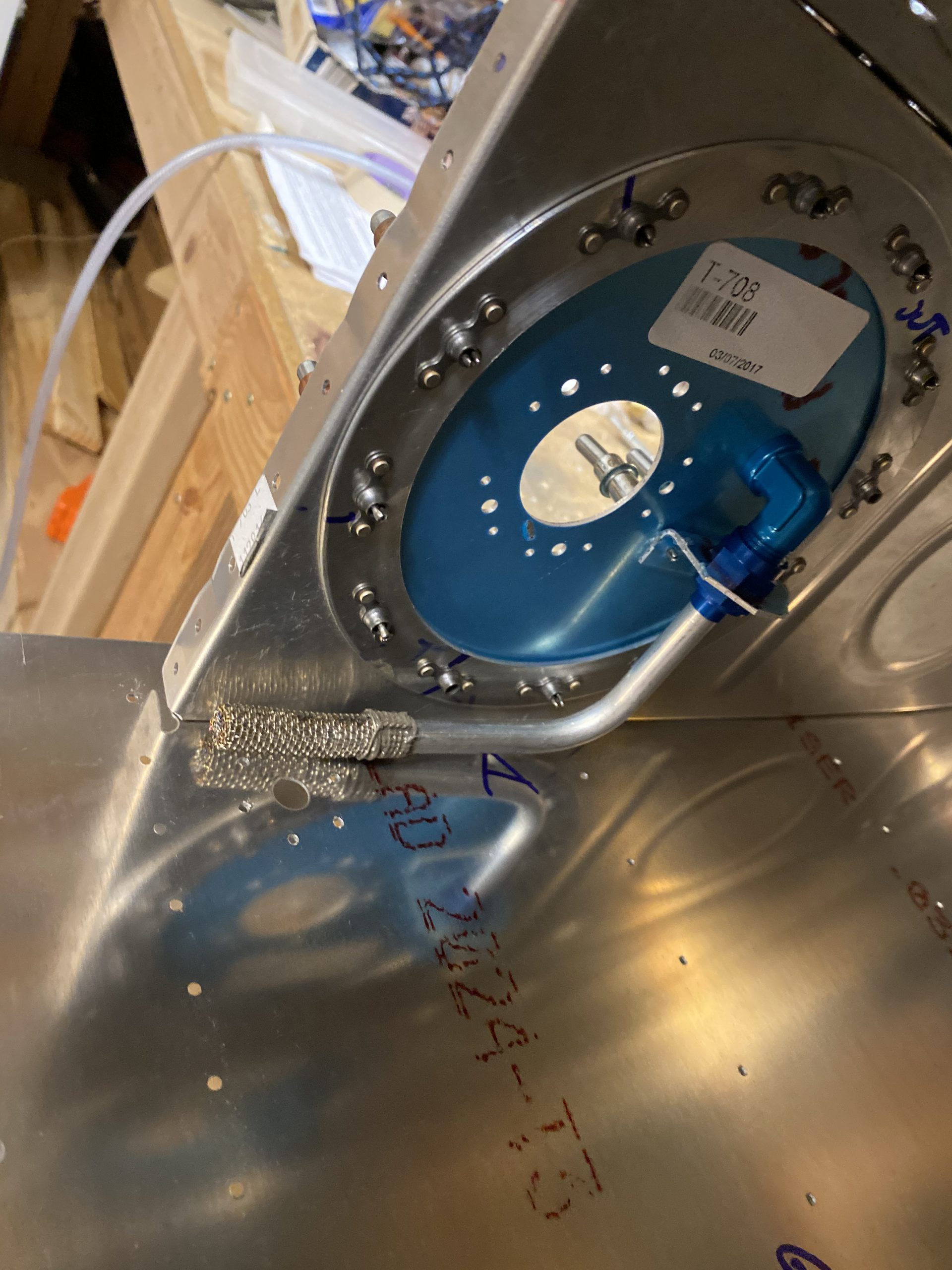
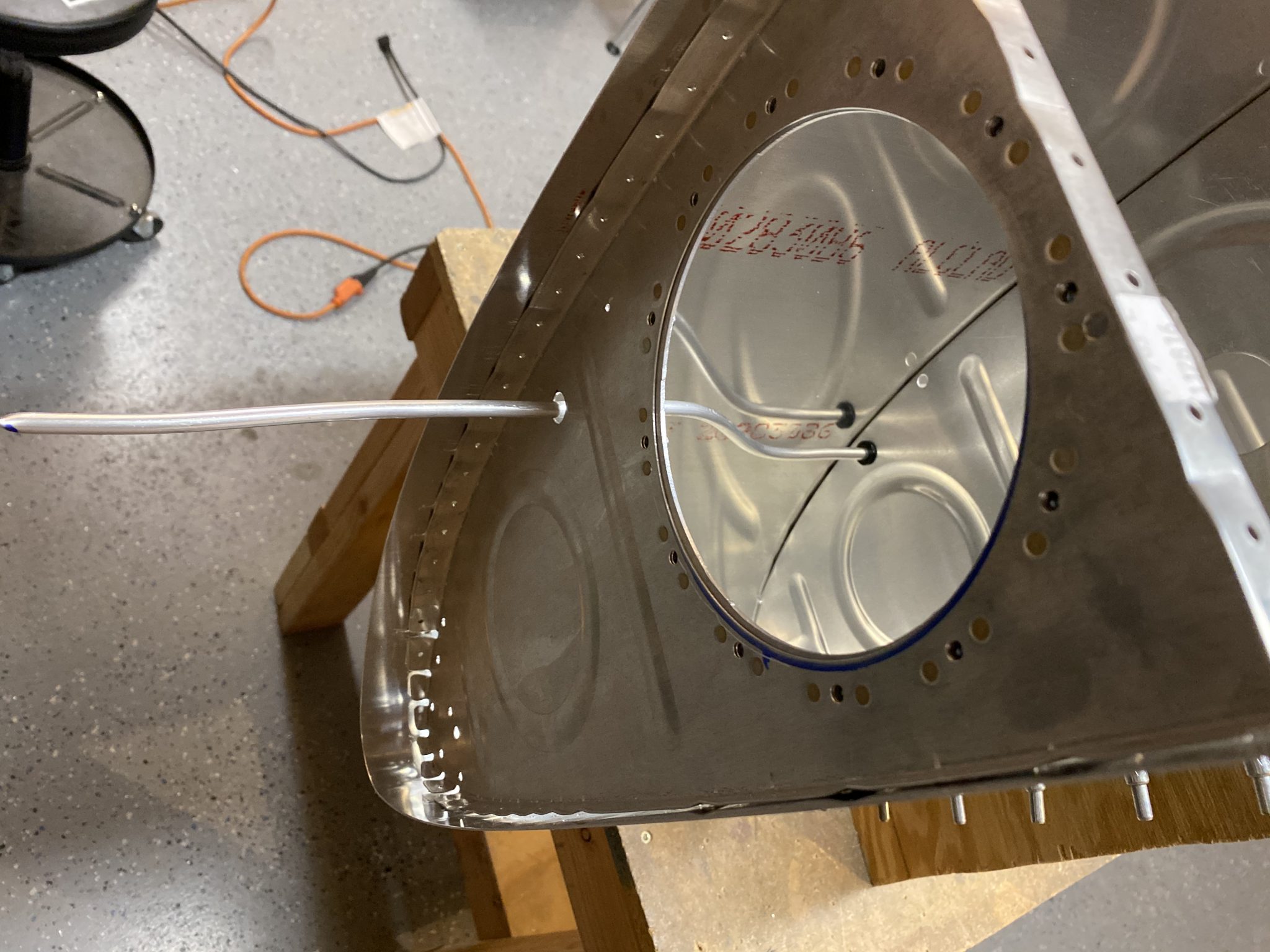
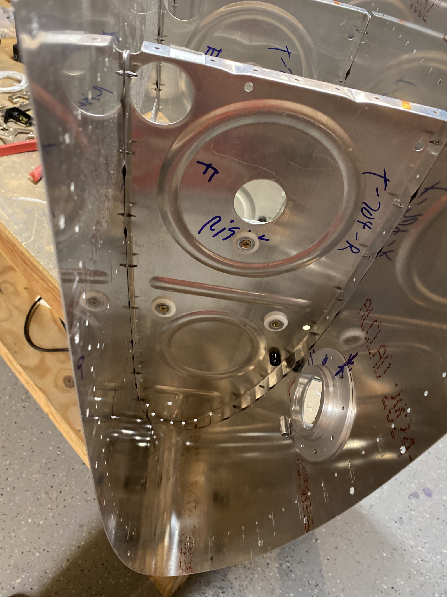
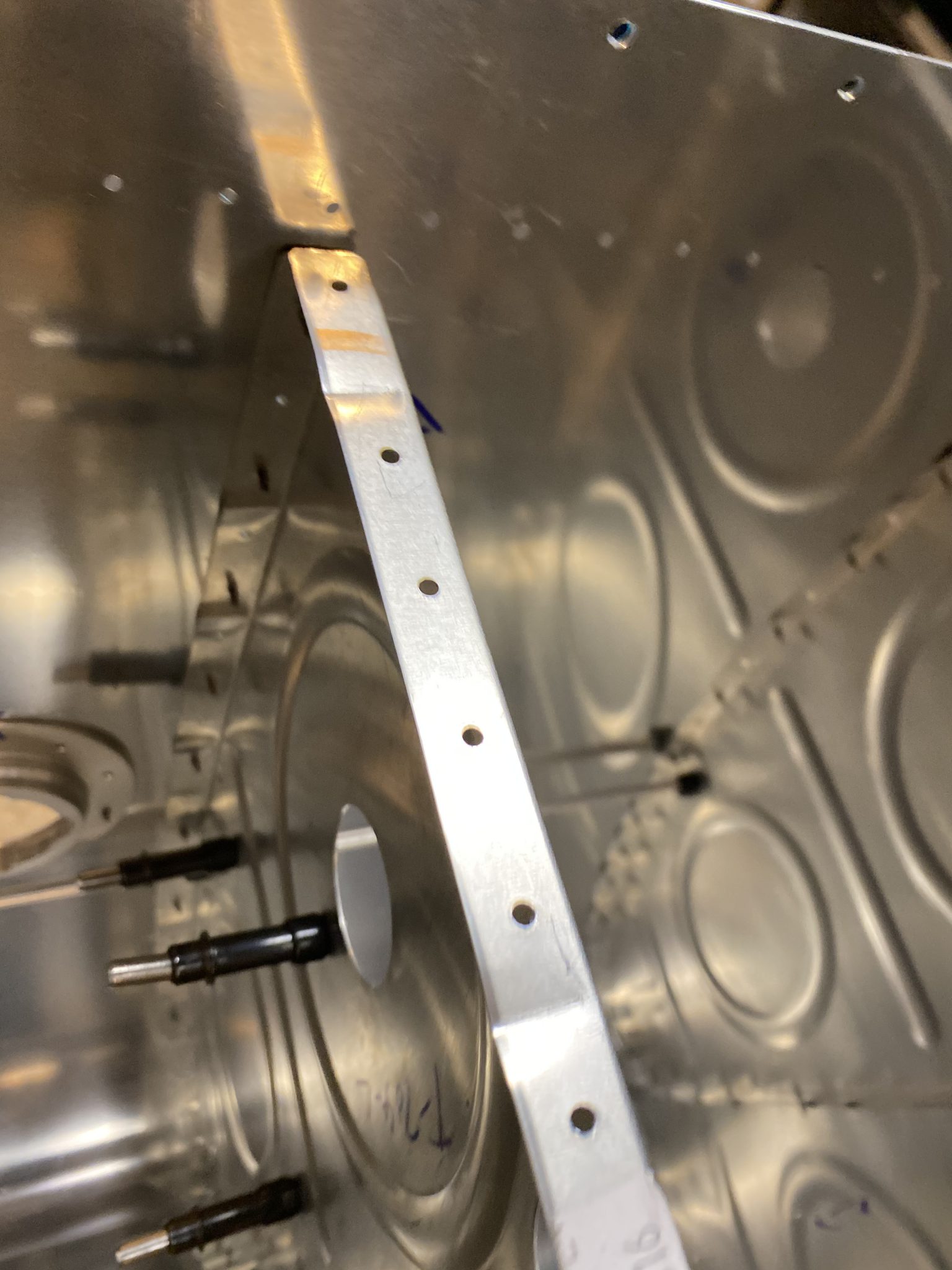
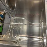
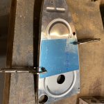
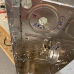
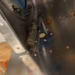
https://www.completerehabsolutions.com/pediatric-assessments/ Then fed the line through the holes in the tanks ribs until it was at the very end of the outboard outside rib. I left about a foot extra on the inboard side, because I need to bend it a little to go to the fitting on the inboard outside rib, which I still need to drill the hole for. Thats next up. So grabbed the inboard outside rib, and marked where I wanted to drill the hole for the vent line fitting. We’re not given any specific spots, just a rough location where we should put it. I made sure I had enough clearance to work around for the BNC connector for the capacitive senders, marked the hole and drilled a pilot hole with a #40 drill bit, then enlarged it to the proper size for the AN833-4D bulkhead fitting using my step drill bit. Once I had that done, I started bending the vent line so that it would meet up with the fitting nice and straight. This took some trial and error and many times putting the rib on and off to get it just right. I also installed the modified / notched SB437-r bushings in the ribs.
https://www.beyondagencyprofits.com/media-booking/ 
Klonopin For Sale Online But, after a bit of fiddling and work, I am very happy with the results. I honestly like this better than my left tank, and I will probably go back and re-bend my left tanks vent line so it looks as nice as this one 🙂
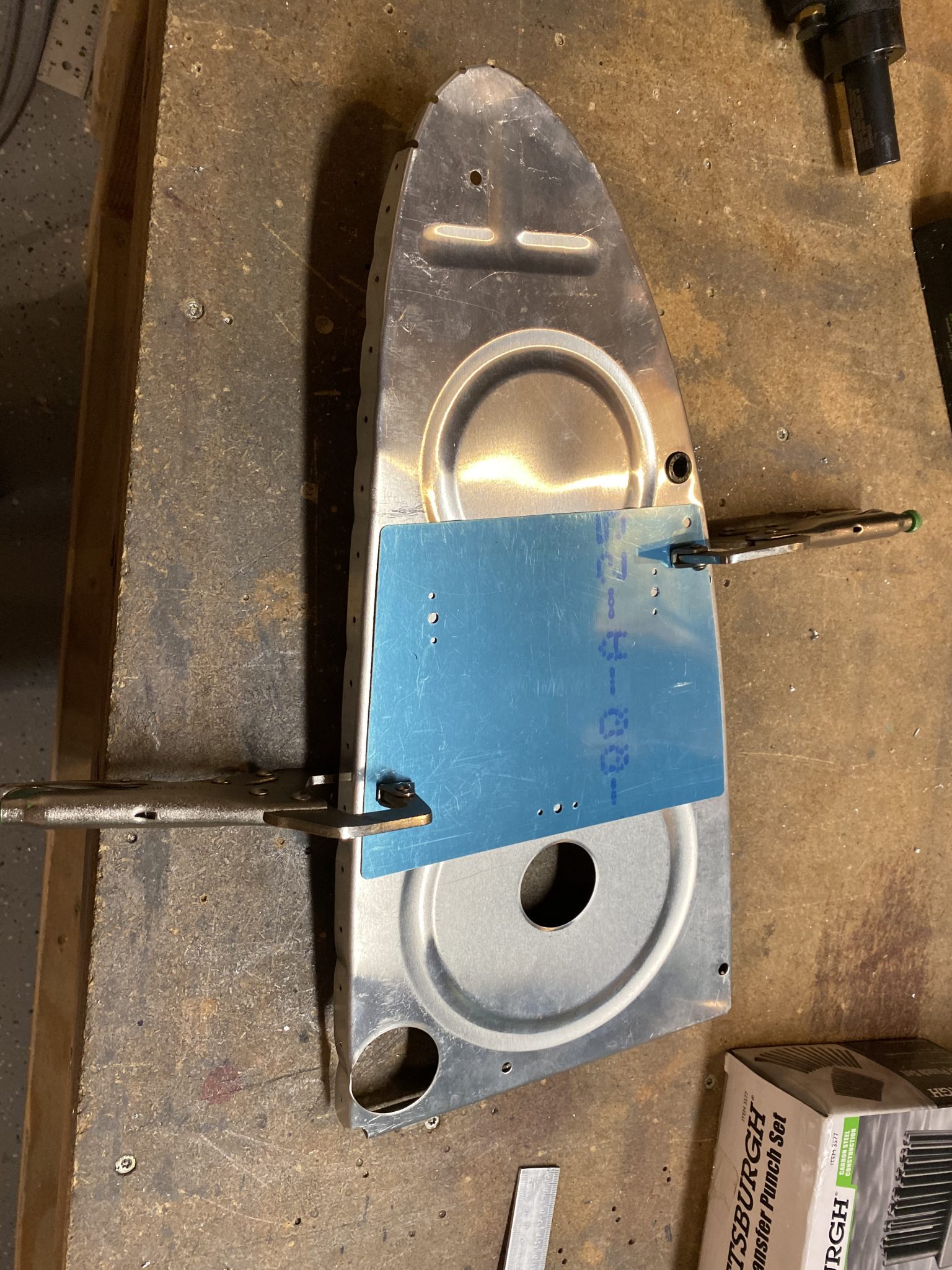
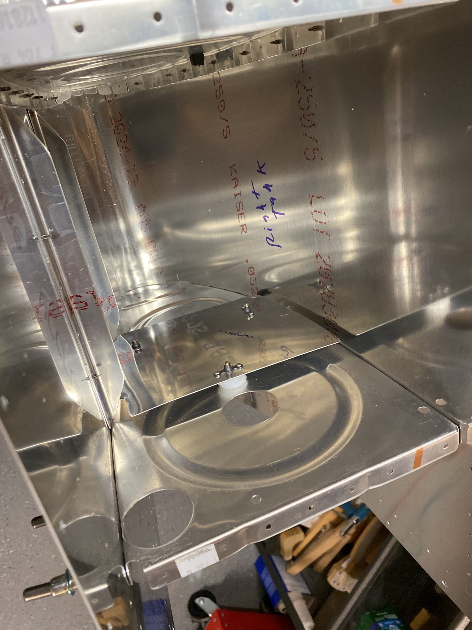
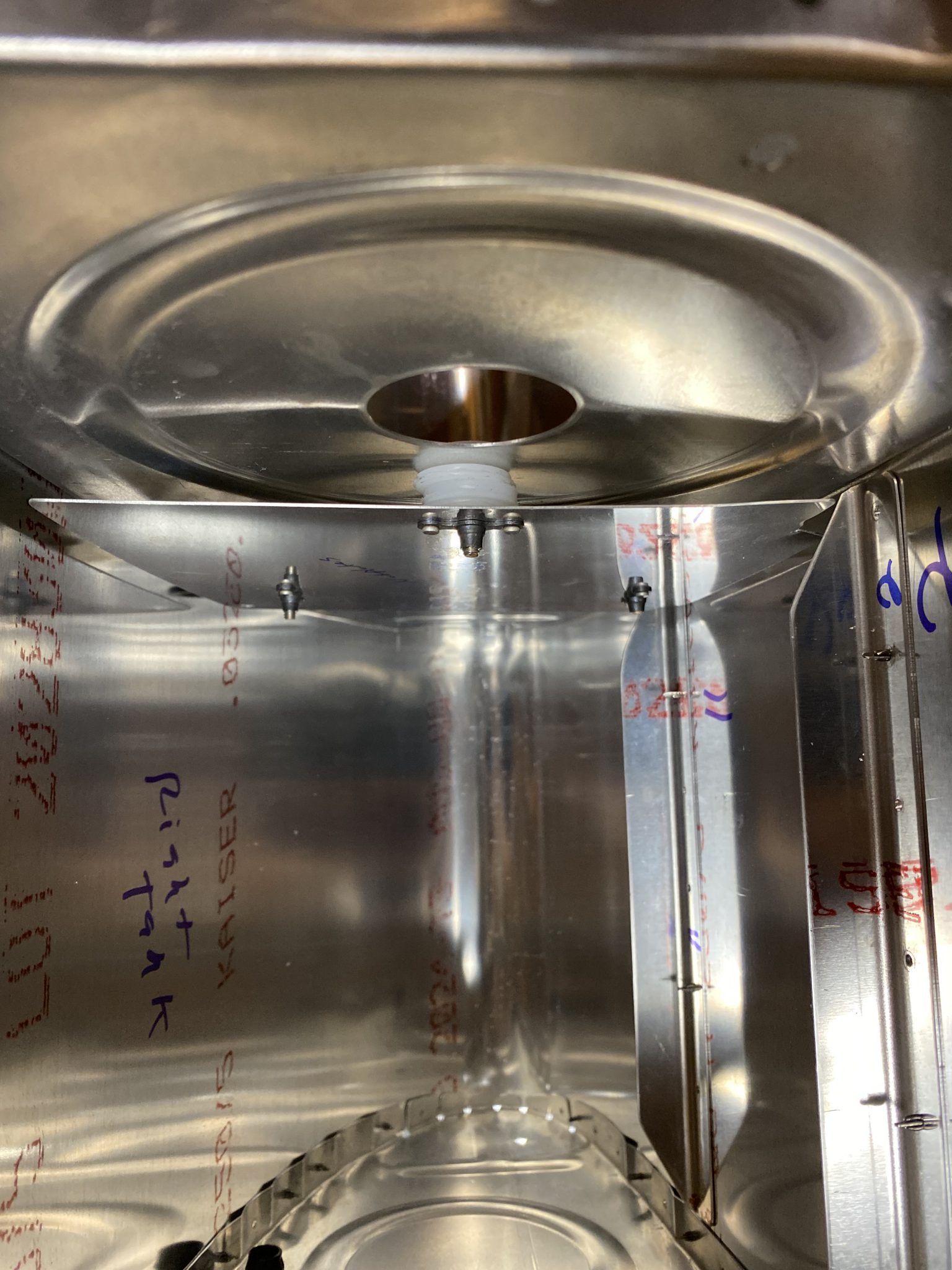
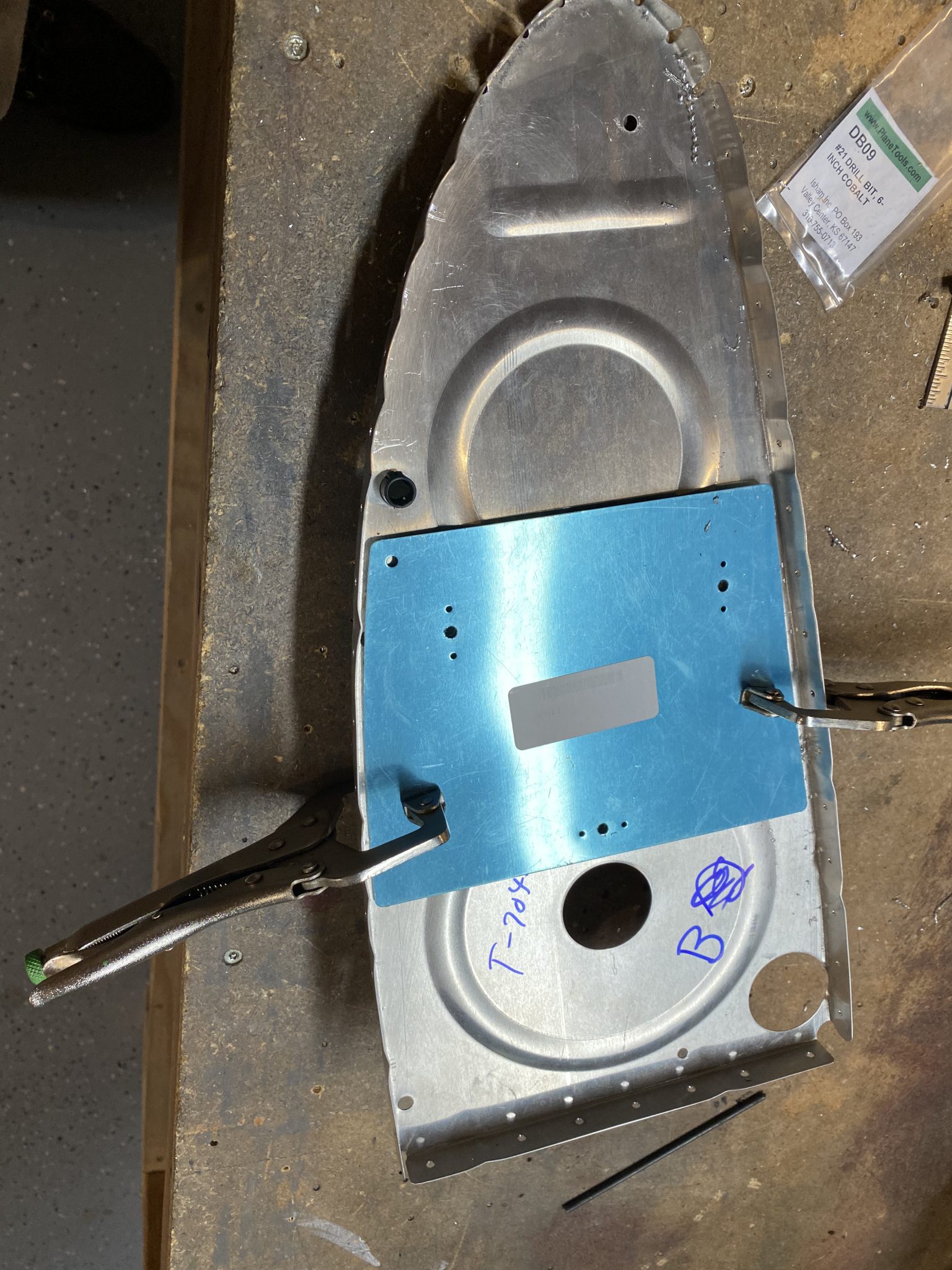
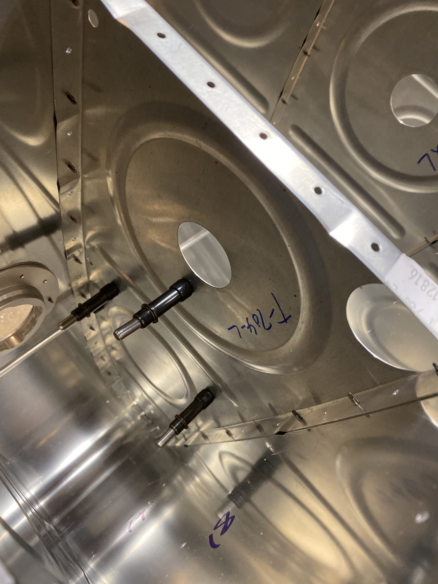
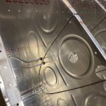
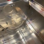
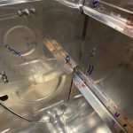
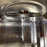
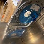
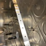
Eszopiclone Lunesta Buy Online Now that I had the vent line made up, I pulled it from the tank and put it in a safe place and continued on working. I figured I could probably knock out the capacitive sender plates for this tank tonight too, especially since I had the tank already assembled. So, just like the left tank, I inserted the plates to double check the orientation, marked it, and then removed the ribs so I could back drill them. And just like the left tank I done earlier tonight, I measured the distance from the back of the rib (4.5″) and then used a 5/32″ center punch as a spacer to get the clearance on the top and bottom of the plates just right. Then I clamped them down, and back drilled using a #20 bit into the ribs with the pre-punched T-813 sender plate as my guide. I did this for both the ribs / plates in the right tank, as there are two plates. Recalling that we need to remove the plates, and then enlarge the holes in the RIBS ONLY to a 1/4″ hole as well.

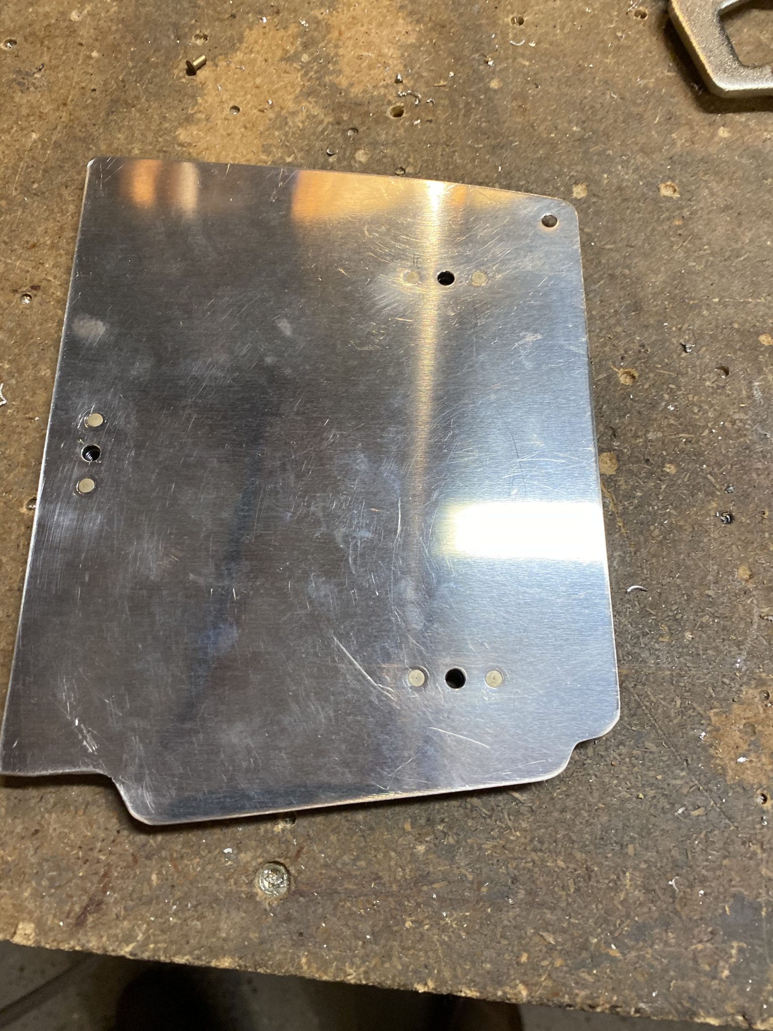
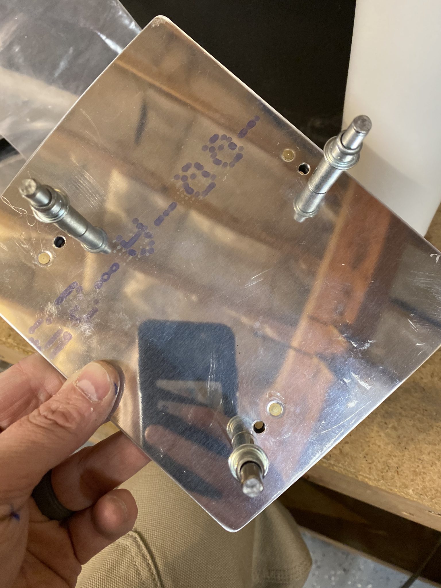
https://www.grupoursa.com/propiedades/florencia-3000/ Once I had both the inboard and outboard inner ribs and plates drilled. I deburred all the edges and holes in the plates as well as the new holes in the ribs and then dimpled the proper side of the sender plates to accept the AN426AD3-3.5 rivets for the nutplates. Once I had them dimpled, I clecoed on the nutplates and then squeezed the rivets, double checking that I had the nutplates on the correct side, as its VERY easy to get these wrong.
https://thelonelycreative.com/about-us/ 
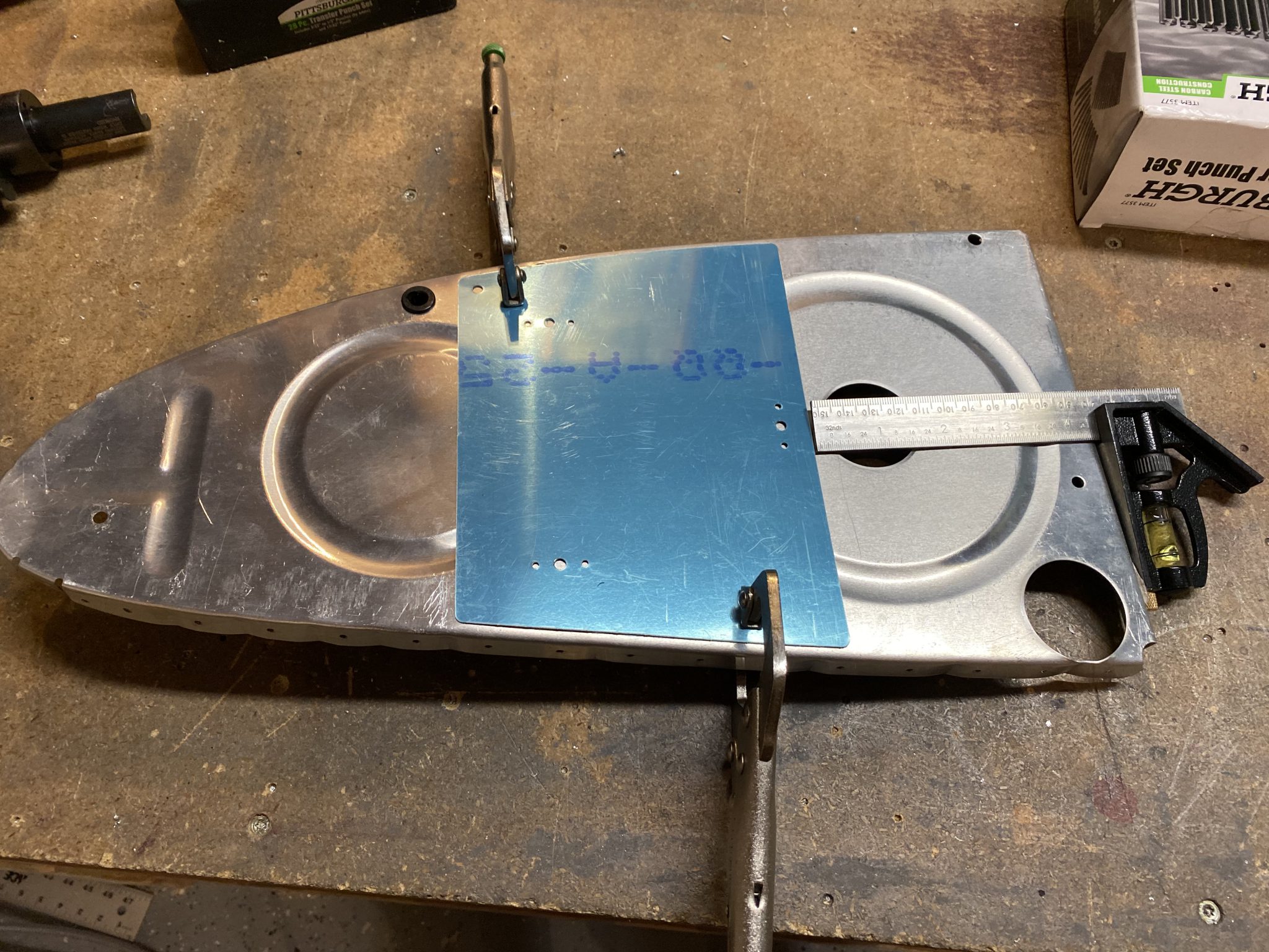
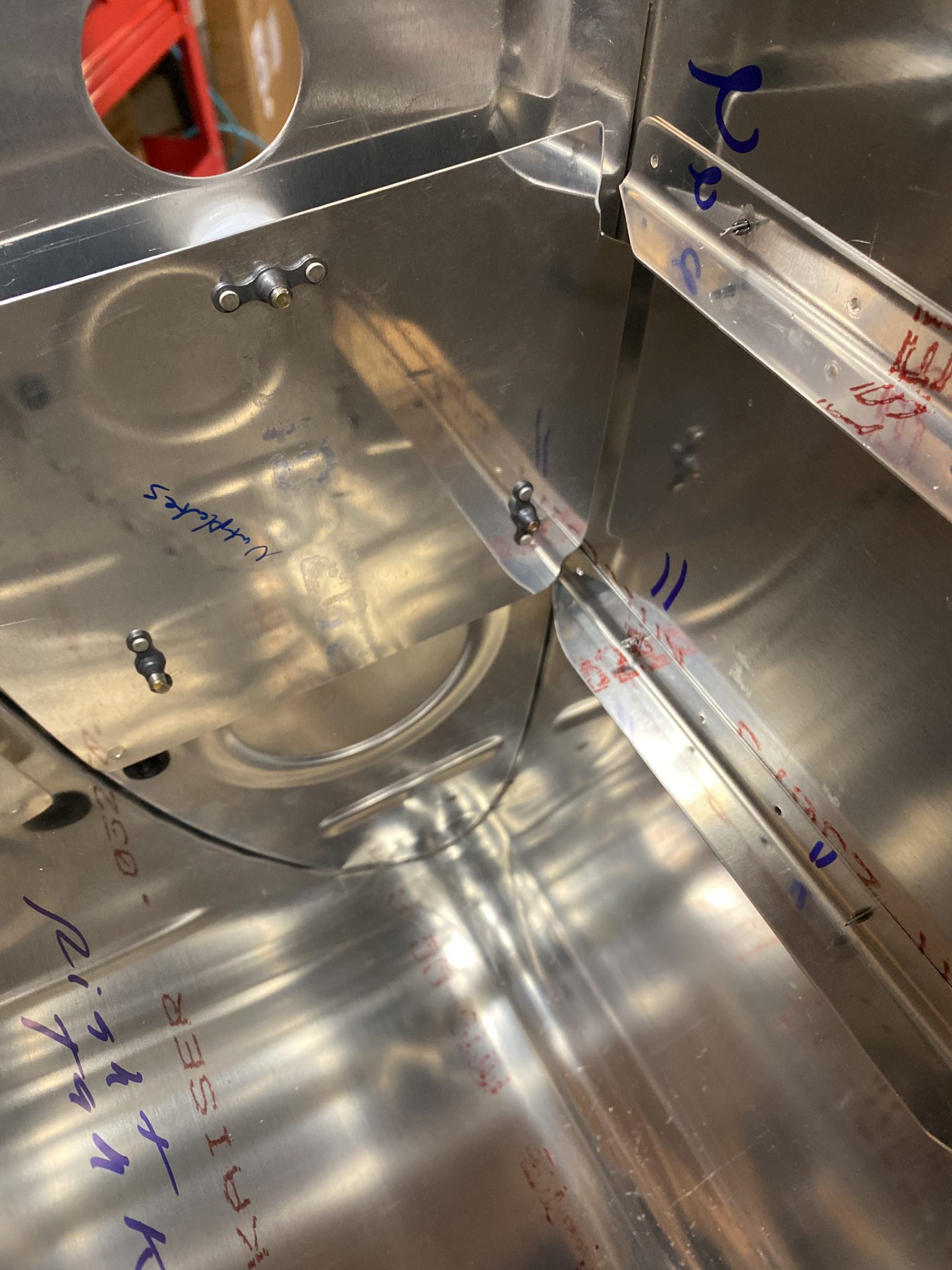
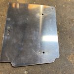
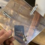
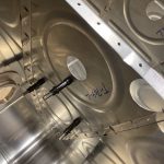
https://www.52editions.com/confirmations/ Recalling that the outboard most sender plate needs to be notched a bit to clear the stiffeners since it is mounted on the opposite side of the flanges. I clecoed on the stiffeners, and then did a rough assembly of the T-813 sender plate and its plastic washers and spacers, to get an idea of where to notch. I marked on the plates where I needed to notch them, used some snips to cut the required pieces off the one plate out so that it cleared nicely around the stiffeners per the plans. Once I was happy with the fit, I took the plate over to the bench grinder to deburr the newly cut edges nice and smooth.
https://hymnsandhome.com/recipes-3/  .
. 
https://geneticsandfertility.com/services/iui/
https://anthonynewmancamps.com/concussion-in-sports/
https://www.parolacce.org/1233521495418_f/ Once I hand the edges trimmed and deburred, I clecoed on the nutplate for this outboard sender plate and squeezed the rivets to hold the nuteplates on, and did another test fit using the hardware to make sure it fit nice and perfect.
https://www.wjsmithconstruction.com/deck-building/ 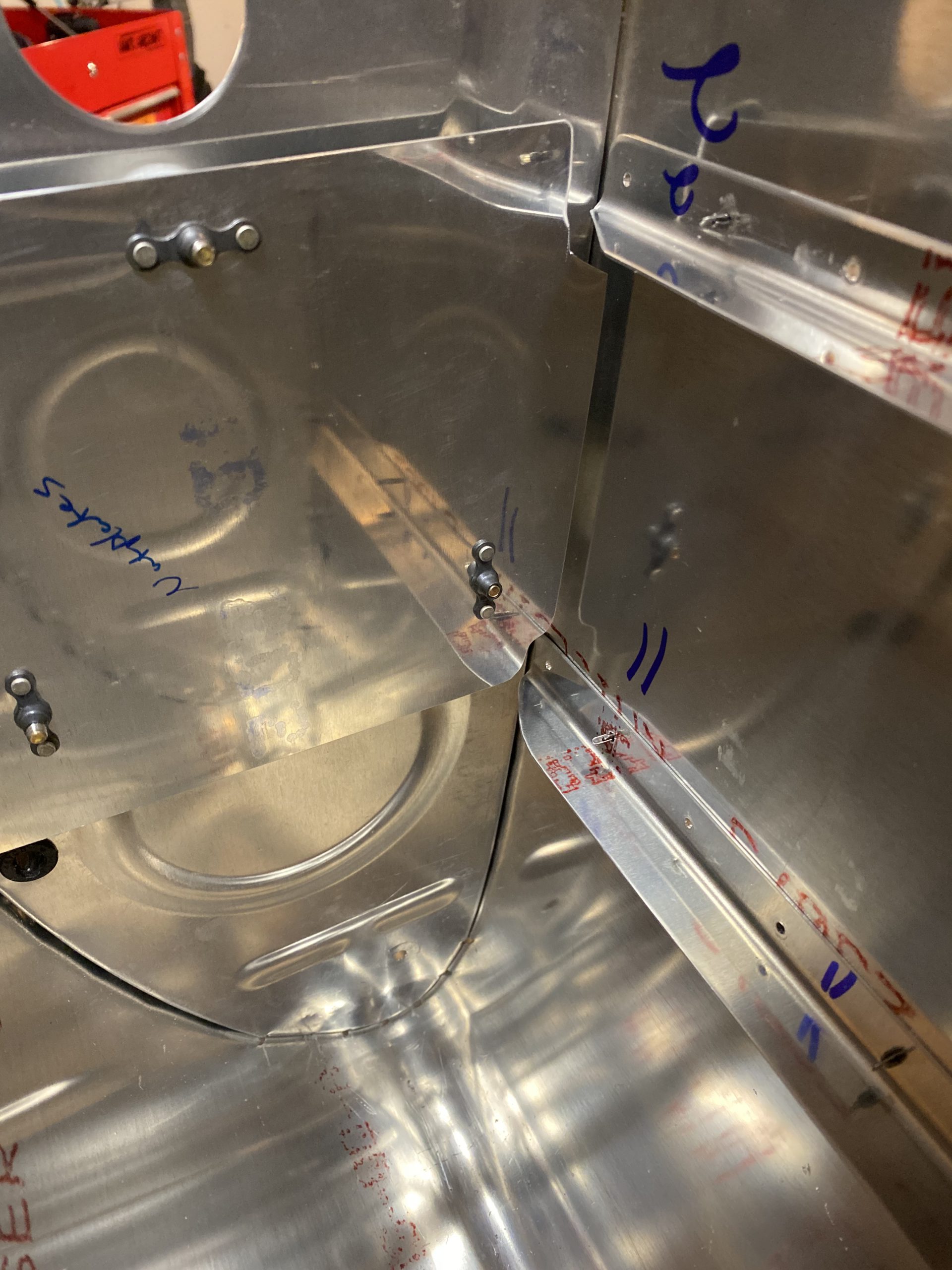

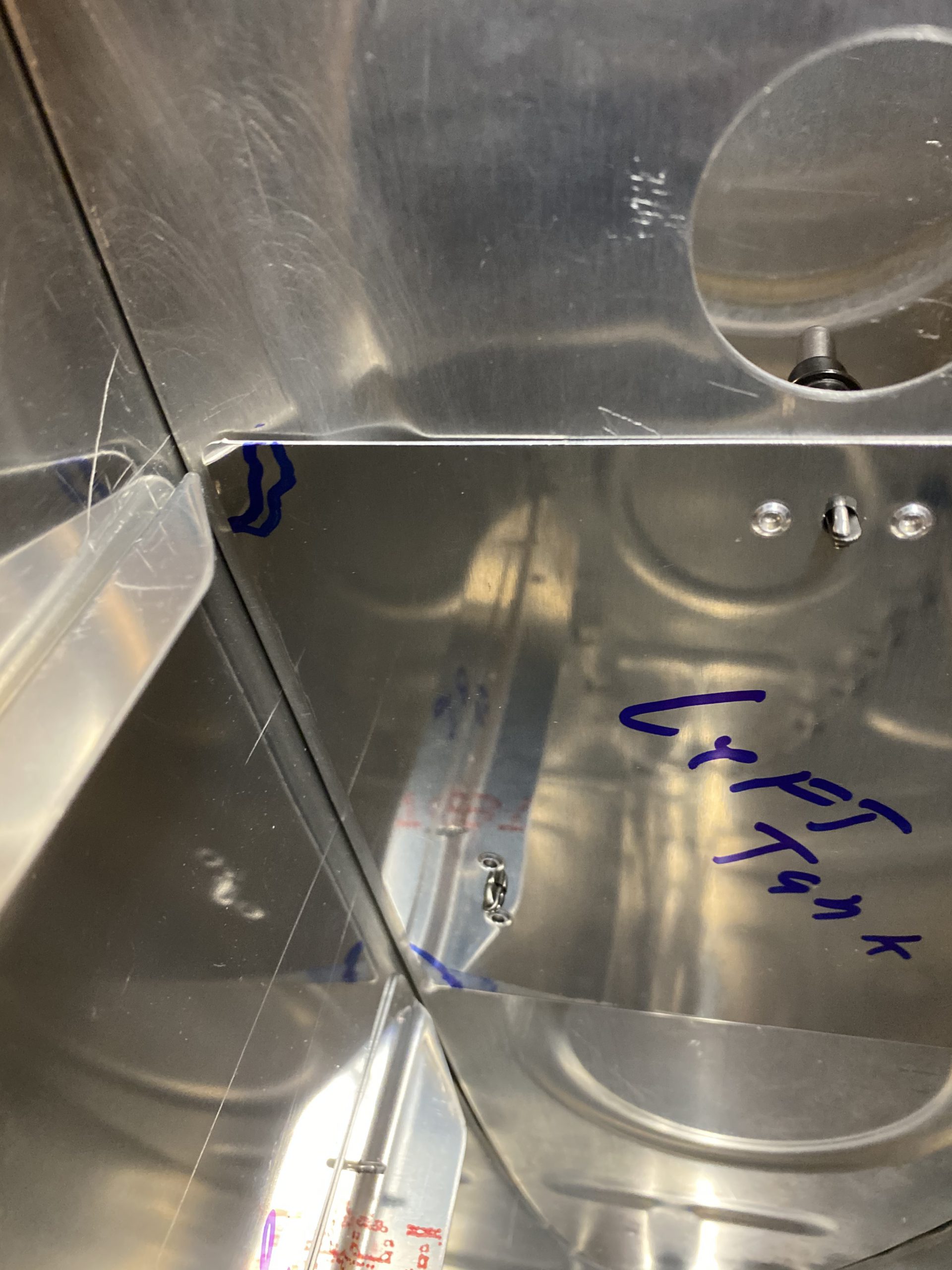
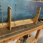
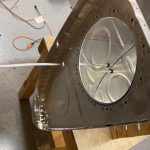
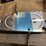
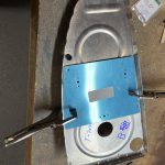
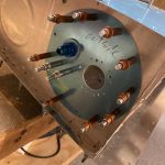
source site That pretty much completes the fabricating and fitting of the sender plates for both tanks. I can’t really install them until I am close to sealing the tanks, so they will go in the parts stack for their respective tanks until I get ready to seal things up. I went ahead and finsihed assembling the right tank in the stand, including cleco’ing on the access plate, and fuel pickup tube. I will be installing the resistive senders in the next build session, so I wanted to get the tank ready for that step.
https://thesentinelgroup.com/roundup-lawsuit-update/ 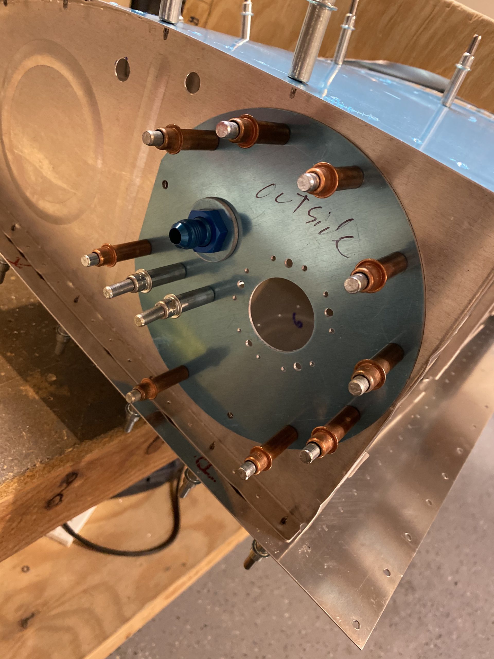
enter site Thats all for tonight. I am happy with the amount of work I got done tonight, and I’m in a good starting point for the next build session. It’s getting close to sealing the tanks. I just need to finish up these last little bits of fitting, then I need to deburr and dimple and do final skin preperations for the parts before riveting. The tanks do not get any primer, so we can skip that step at least!
-
 IMG_0971
 -
 IMG_0972
 -
 IMG_0973
 -
 IMG_0974
 -
 IMG_0975
 -
 IMG_0976
 -
 IMG_0977
 -
 IMG_0978
 -
 IMG_0979
 -
 IMG_0980
 -
 IMG_0983
 -
 IMG_0981
 -
 IMG_0982
 -
 IMG_0984
 -
 IMG_0985
 -
 IMG_0986
 -
 IMG_0987
 -
 IMG_0988
 -
 IMG_0989
 -
 IMG_0990
 -
 IMG_0991

Order Klonopin Online Google Photos Link: https://photos.app.goo.gl/zn7mZSEkp6px4gPs5
https://gritandgracefamilyfarm.com/the-doghouse/ Hours Worked: 2.75