Rib Flange Straightening — Part 1

Fighting off some sort of cold/sinus infection, I didn’t feel like putting in a whole bunch of work tonight, and I am still studying up for an Ansible exam but I did manage to knock out straightening the flanges on all of the wing ribs. All the ribs are pre-formed by Vans, but due to the punch and forming process, the flanges are not at a perfect 90 degrees to the the rib, so we need to bend them to a perfect 90.  The old way is to use a pair of hand seamers and do it all manually, checking with a square to get your bends perfect, but theres a better way.

A few months ago, while I was waiting on my wing kit to ship, I built a very neat little tool to help with this process.  I had seen several other builders make something similar, and they all raved about it, so I built one for myself.

It’s a pretty simple little tool. It’s made from a 2×4, a 1.5 x 1.5 piece of oak and some metal.  The anvil portion of the 2×4 (clamped down to my work bench) is angled at about 11 degrees, while the press handle is made from the 1.5×1.5 oak.  The 11 degree angle bends the flanges to slightly beyond 90 degrees, because the aluminum will flex back about 10 or so degrees, which leaves the flange at a perfect 90!  You can see how the rib sits in the tool here:

The 2×4 on the left serves as the “anvil” that the flange is formed against, and you can just make out the 11 degree angle on the face of the 2×4 (its tilting toward your right).  Also, notice how the handle portion (the oak 1.5x1x5 handle) also has a angle cut on the bottom.  This is a 22.5 degree cut I made on my mitre saw so that all the bumps and ridges in the rib would not get damaged.  They fit very nicely under this angled portion as you can see in that photo above.  Here is what it looks like without a rib in it:

To do the work, I just put the rib, flange facing upwards in the tool and apply pressure on the handle to bend the rib.  The result is a perfect 90 degree bend on the flanges! I can process an entire rib in about 20 seconds on this tool.  I’ll update this post with a video describing how to make the tool, and how to use it.  I think it cost me about $15 to make.  All in all, I was able to knock out all of the inner ribs for both wings in a little over an hour!

Google Photos Link: https://photos.app.goo.gl/RiI3OipxFfTQ4UKf2

Hours Worked:1.25

Wing Rib Deburring — Part 5 and DONE!

I wrapped up all the wing rib deburring tonight.  All that was left were the ribs for the fuel tanks, but like all the other leading edge ribs, they have all those little tiny flanges, and each one needs to be deburred.

I spent a little over an hour knocking the rest of these things out and then decided to do a little work on my flange straightening tool.  I had picked up a “edge rounder” routing bit so I could smooth the handle down a bit a few days ago, so I decided to move on to that for the rest of the evening.  I am not going to count those hours in the build log however, since I was pretty much just polishing up on the tool I made to help me get the rib flanges all at a 90 degree angle.  I’ll do that tomorrow and give details on it.

That (thankfully) wraps up all of the edge deburring for all of these ribs.  It took a lot of time, and wasn’t very fun but it had to be done.  I am just glad its over, so I can move on to some other task for a change! Here’s the stack of ribs I got done tonight.  16 total (I think that was the count):

Google Photos Link:  https://photos.app.goo.gl/vnPTL6Qy6oCavrcl1

Hours Worked:1.25

Wing Rib Deburring Part 4

One Hour…thats all I managed to work on the airplane tonight.  I’ve got a lot going on with work and family right now, so I don’t have as much spare time to get down to the airplane factory and build the RV-7.  Spending a lot of time learning up on Ansible and Satellite 6 as well as IdM (Three Red Hat products I deliver for our customers), and with Dad in the hospital recovering from surgery, I don’t find myself with any time left in the days.  But, any step forward is a good step, no matter how small.

Tonight, I simply finished up deburring 14 leading edge ribs, which includes all the little tabs and slots on the flanges.  Man, these things are a pain in the ass to do. It’s not so much difficult work, as it is tedious and boring and repetitive. It’s got to be done though!  I am still using emery cloth folded up to fit into the slots, and it seems to be working good enough.  I have about another 15 or 20 leading edge ribs left to do.

Here’s the aftermath of all that deburring:

I’ll probably just keep at it with the emery cloth.  one strip seems to last a pretty good while and they are cheap.  I’m not going to waste any more time and effort on trying to use a dremel or die grinder. Thats pretty much it for tonight.  These wing rib posts are always pretty boring and simple on just about every builders online log, and I can see why.

Google Photos Link: https://photos.app.goo.gl/dp5J5V1LqyJAbrTD2

Hours Worked:1

Wing Rib Deburring Part 3

After discussing the use of the scotchbrite cones with folks on the forums, I decided to go pick up some emery cloth and sandpaper to deburr the gaps in the rib flanges.  Making the cones, using them and making more was taking too much time. I only have the softer 1″ scotchbrite wheels, and it appears everyone is using the harder, grey looking ones.   After driving all over Chattanooga, I finally found some emery cloth at Tractor Supply.   I decided I would gently clamp the ribs down to my bench and then use strips of emery cloth like dental floss to get into the gaps of the flanges. I cut the emery cloth into about 3/4″ to 1/2″ strips that were just wide tall enough to fully cover the flanges, and that worked out pretty good.

I was able to get about 4 or 5 ribs using a strip of emery cloth and that was being conservative.  I probably could have gotten more, but this stuff is pretty cheap, and I can make about 4 strips or more from a sheet.  I was able to get the remaining 14 inboard and outboard ribs done using this method pretty quickly.  I decided to move on to the fuel tank ribs and knock them out as well.  Using the same method as above, they went pretty easily too, but I took extra caution to make sure the leading edges of these ribs were very smooth.  The plans tells us to make sure we also smooth out the bumps from the reliefs on the leading edge flanges because there are some complex curves here.  I started out using my bastard file to work the edges and bumps on the fuel tank ribs, but soon realized I could use my scotchbrite wheel on the bench grinder to make this easier.

And it did! Using the scotchbrite wheel, I put the grinder on the slowest speed it had, so I didn’t burn through the thin metal to quickly.  This worked out great! I could smooth down the leading edges very smoothly in no time using this method.  They were really smooth, and the skins should lay very nicely around this complex curve with no bumps or roughness.

I decided to carry on and go ahead and knock out all the leading edge smoothing on all the leading edge ribs using my scotchbrite wheel.  I was able to get them all done in about 20 minutes or so.  Now, I still need to smooth down gaps in the flanges for all the leading edge ribs, but I decided I’d leave that for tomorrows session.  I ended the night on a good note, and hopefully put a dent in the rib workload.  I’ll be glad when this part of the wing build is done! HAH!.  Here’s all the photos from tonight:

Google Photos Link: https://goo.gl/photos/2a8y2CEpbsAxcYJ17

Hours Worked:2.5

Wing Rib Deburring Part 2

After taking time away from building for a few days to spend some time with my family, I found a little time tonight to work on the ribs.  I am in the process of deburring all the ribs, and at the point of deburring all the little crevices and corners of them now.  In the last session, I cleaned up the lightening holes and edges.

I had read on the Vans Airforce Forums about a trick to help with deburring.  You take a small scothcbrite wheel, cut it into wedges and then use them on a dremel to get in all the small grooves of the ribs.  I tried this tonight, but not sure I am happy with how it worked.  I may have the wrong scotchbrite wheels for this.

I gave it a shot on my dremel, and the wheel just didn’t seem to do a good job of deburring, and took a lot of work it seemed.  I worked for about an hour or so, and only got about 6 ribs done.   The wedge would only last about 1 or 2 ribs before needing to be replaced, which took even more time to cut and shape into a cone.  It kind of sucked. After about an hour, I said screw it, and decided to ask a question on the forums about which wheels they were using for this before I waste any more time on trying this.  I called it quits for tonight.  I think I got about 6 ribs done, oh well.  Here’s the photos:

Google Photos Link: https://goo.gl/photos/Vz1KBqVCqNzYXekN8

Hours Worked:1

Deburring Wing Ribs

It’s that time in the build:  Wing rib prep.  This is probably the only part of the build that most people enjoy the least.  There are 56 total ribs, and all of them need to be prepped before you can start building the wing skeleton.  That means the following things need to be done:

  1. Deburr all the flange edges
  2. Deburr all the edges of the lightening holes.
  3. Make sure al the flanges are bent to 90 degrees
  4. Flute all the ribs to make sure they are perfectly straight
  5. Scuff them and clean them
  6. Prime them.

As you can see, multiply those 6 steps times 56 ribs and you can get an idea that a lot of man hours goes into these things, and its repetitive work.  However, I figured this would be a good time to use these repetitive tasks as a sort of relaxation technique; listening to good music and just work away at them.  I do look forward to getting in the shop and doing some work with my hands, because all day long I sit behind a computer automating systems deployments for companies.  So, lets get after it!

First up, I had read from several other builders on Vans Airforce that its easier to deburr all the lightening holes using a small scotchbrite wheel chucked into a die grinder.  I decided to try it a little differently.  I chucked it up in my drill press, and then configured my drill press to run at its max speed of about 3600 RPM.  It’s not as fast as a die grinder, but it worked out pretty nicely.

I carried all the ribs out to the garage, where my drill press is, and then rocked out to some BlackBerry Smoke and deburred all those lightening holes.  These things need to be smooth because you have to reach through them during the build process to rivet skins, and do other work inside the wings.  The small scotchbrite wheels I bought are pretty soft for some reason, so I ended up going through one wheel per about 4 or 5 ribs.  I bought 100 of them so I have plenty and after about a half hour or so I had all the lightening holes deburred.

Then it was time to deburr all the flange edges. This is a process I have done many many times on the scotchbrite wheel on my bench grinder.  I deburred every single rib flange on the bench grinder and stacked them up in a neat pile for the next process.  Unfortunately, the deburring wheel on the grinder can’t get in the small gaps between the flanges, so I am will have to do those using a scotchbrite pad or some other process.  I can see that’s going to take some time, especially on the leading edge ribs where there is a lot of little tabs to debur.  I think I may give this a try, as suggested on the VAF Forums.  Thats it for tonight.  I am covered in deburring dust, I am glad I wore a respirator and safety glasses for this.  Not a lot of photos form tonight, but here’s what I took:

Google Photos Link: https://goo.gl/photos/KaFALHx8tGPwWHn1A

Hours Worked: 2.5

Riveting the Wings Rear Spar

I found a little time to finish up the rear spars for the wings tonight.  I had let the AKZO cure for a few days while Tammy was off so we did family time during those days.  Tammy was back at work tonight, so I pulled the primered parts from the booth and riveted them together. I started out on the left rear spar since it is the one that is specifically shown in the plans.  The right one is not in the plans, and Vans assumes we know how to mirror the left for the right wing.  First thing was to cleco the doublers to the rear spar as well as the reinforcement forks and its doubler plate.

Next, we have to carefully match up which holes need rivets, as some of the holes will be used to hold the spar, doublers ribs and even the gap seals for the aileron and flaps. I used masking tape at first to cover up the holes that don’t get rivets right now and then clecoed everything together.

In the last photo above, you can see where I just used a sharpie to mark the holes the DO NOT get rivets instead of using masking tape.  After looking over the plans, we are only going to be using three different rivet sizes.  AN470AD4-4 for the thinner doubler plates, AN470AD4-6 for the reinforcement fork to rear spar, and finally AN470AD4-8 for the reinforcement fork, its doubler plate and the rear spar.  To make my work more efficient, I decided to start with the smaller rivets first, setup my squeezer for them and then do all of the 4-4 rivets on both rear spars, and then just adjust the squeezer for the next size and repeat.  So, I went ahead and clecoed the right wing rear spar parts together, making sure to mirror their orientation to the left wing.  Since there are only a few rivets on some of these doubler, I just decided to circle the ones I needed to squeeze instead of using masking tape for the right rear spar.

Then it was time to squeeze.  I started out with the AN470AD4-4 rivets and adjusted my squeezer until the rivet was setting perfectly against the rivet gauge, and the I went and squeezed all of the 4-4 sized rivets on both the left and right rear spars, always checking each one with the rivet gauge (I am picky about this). Once I had them all done, I moved up to the AN470AD4-6 rivets and did the same thing for both sides, and then finally finished up by riveting the handful of the larger AN470AD4-8 rivets. Each rivet was checked with the gauge for precision.

You’ll notice that on the reinforcement fork, I set the rivets with the manufactured head on the thickest metal.  While this isn’t technically correct, I needed to be sure I would have space to squeeze the wing skins in the holes directly above those rivets.  However, on the thick doubler plate to reinforcement fork, you’ll notice that I did indeed set these with the manufactured head towards the thinnest (rear spar channel) metal which is technically how it should be.  While there is debate on how this should be done, this will be fine since even though the rear spar channel is indeed thinner than the reinforcement fork, it is still a thick piece of metal itself.  Had I been riveting the very thin skins to something thicker, I would made sure to put the manufactured head on the skin side. Here’s the required selfie of me and the completed rear spars to help prove I actually did the work for the repairmans certificate.

And that is pretty much it for tonights session.  It was only about 1 hour and 45 minutes of work for tonight, but this actually completed the assembly of the rear spars.  They will go back on the shelf along with the main spars until I have all these ribs deburred, drilled and primed; then I’ll pull them off the shelf and build the wing skeletons. Rib prep will be consuming quite a bit of time for the next couple of weeks, so I am going to have my metal wing stands built during this time frame, hoping they’ll be ready by the time I am done with the ribs. Here’s the photos from tonights work:

  • IMG_1739
    IMG_1739
  • IMG_1735
    IMG_1735
  • IMG_1734
    IMG_1734
  • IMG_1733
    IMG_1733
  • IMG_1732
    IMG_1732
  • IMG_1731
    IMG_1731
  • IMG_1730
    IMG_1730
  • IMG_1729
    IMG_1729
  • IMG_1728
    IMG_1728
  • IMG_1727
    IMG_1727
  • IMG_1726
    IMG_1726
  • IMG_1725
    IMG_1725
  • IMG_1724
    IMG_1724
  • IMG_1723
    IMG_1723
  • IMG_1722
    IMG_1722
  • IMG_1721
    IMG_1721
  • IMG_1720
    IMG_1720
  • IMG_20170628_224636
    IMG_20170628_224636

Google Photos Link:  https://goo.gl/photos/NX9zek3fvUcWvmSR7

Hours Worked: 1.75

Priming the Rear Spar

Another priming day.  I really don’t enjoy priming, its probably the only part of building an airplane that I despise.  It very well could be my process, so I think I will try something different on the ribs.  However, I followed my normal routine for the spar parts:

  1. Scuff all the parts with maroon scotchbrite pads.  My goal was to not take off the alclad, but give the primer a good surface to adhere to.  I figure having alclad AND AKZO primer would give me good protection.
  2. Clean the parts with acetone.  This gets rid of oils, scuffing dust, and other contaminants that would cause the primer to not stick.  I have found I have to clean each part three times with a fresh paper towel before the paper towel comes up clean.
  3. Spray the parts with primer.

Now, this may not seem like a lot of work, but all that scuffing and cleaning is boring and very tiresome (repetitive).  I am seriously considering switching methods to the Alumaprep, Alodine and primer methods as they dont require no where near the scrubbing and scuffing.  I could just dunk the parts in bulk into tubs of the stuff and let it do its magic.

Anyways, I followed my normal procedure for now, and scuffed up all the parts, cleaned them with acetone and then sprayed AKZO.  Here’s the photos of where I had them all scuffed up, cleaned and re-marked ready for priming.

I will admit a mistake:

It’s hard to see but I only mixed up about 3 ounces of AKZO (1.5 of parts A and B). I let it have its 30 minute induction time, while I suited up.  I thought it would be enough but I learned about halfway through my spray session that it was not enough.  I was only able to finish about 90% of the parts, and I needed to go back and touch up some bare spots on the spars.  SO… thats my mistake.  I had to mix up a second batch, this time doing another 2 ounces of mixed primer and let it sit another 30 minutes to induct.  After it was ready, I finished up my priming session, and left the parts in the booth so the offgases would get ventilated outside.  AKZO has a tendency to off-gas as its curing, and its a strong smell, so they can hang out in the booth for a day or two and cure.

Of course, heres the painter selfie for proof that I did the work

Here’s all the photos from tonights work. I’ll add the rest of the photos when the parts cure and I can get them out of the booth and in to good light to snap some photos.

  • IMG_1719
    IMG_1719
  • IMG_1718
    IMG_1718
  • IMG_1717
    IMG_1717
  • IMG_1716
    IMG_1716
  • IMG_20170625_193516
    IMG_20170625_193516

Google Photos link:

Hours Worked: 3.5

Prepping the Rear Spar

There wasn’t much left to do on the rear spars except finish getting them ready for priming, and then riveting.  The bulk of tonights work was deburring all the holes, so thats where I started off.  I deburred all the holes in the doubler plates (W-707E, and F), reinforcement fork (W-707G) and reinforcement doubler (W707D), and the rear spar main channel web (W-707A). Once I had both sides of all the parts deburred for the left wing, I swapped over to the right wing and did the same there.  There wasn’t much to photograph for this work, since its just deburring all these holes.

I realized I didn’t drill the holes on the flanges of the doubler plates W-707E and W-707F so I clecoe’d them to the rear spar and then match drilled using the holes in the flange as a guide. Once I had the holes drilled, I followed up by deburring them as well.

I read a little bit ahead in the plans and noticed that Vans gives us some warnings of things that we should address now before we rivet the rear spar together.  The first thing is that the outboard doubler (W-707F) needs to be countersunk for a few rivets.  After looking over the plans, I see there are 4 holes on the most outboard of the rear spare that calls for AN426AD4-5 flush head rivets.  Well, instead of machine countersinking this fairly thin metal, I decided to just use my DRDT-2 dimpler, since it would easily handle this thickness.  I dimpled the W-707F doubler and then followed up with dimpling the rear spar channel to match.

The next thing Vans warns about before riveting is that we should probably go ahead and final drill to #40 and then dimple the rear spar top flange because when we rivet on the reinforcement fork and its doubler plate, it would be difficult to dimple them afterwards. So, I broke out the drill with a #40 bit, final drilled the holes, and the used my squeezer to dimple the rear spars top flange holes all the way to the end of where the reinforcement bar would land.

I also decided to go ahead and dimple the rear spar top flange where the doublers (W-707E and F) attach just so they wouldn’t be in the way.  I final drilled to #40, and then used the squeezer to dimple the holes on the rear spar flange, as well as the doubler plate itself and made sure they still would nest together.  The squeezer very slightly bent both pieces to a 90 degree angle, where it normally is a bit more angled, so I used my hand seamers to gently bend both pieces back to their normal position.  It was a very gradual bend.  After completing all the above on both wings, I called it a night.  The parts are ready to be primed, which I will probably do tomorrow. Here’s the photos from tonights work:

Google photos Link: https://goo.gl/photos/vYgtM8yGBy4hzTXNA

Hours Worked: 2.5

Assembling the Rear Spar

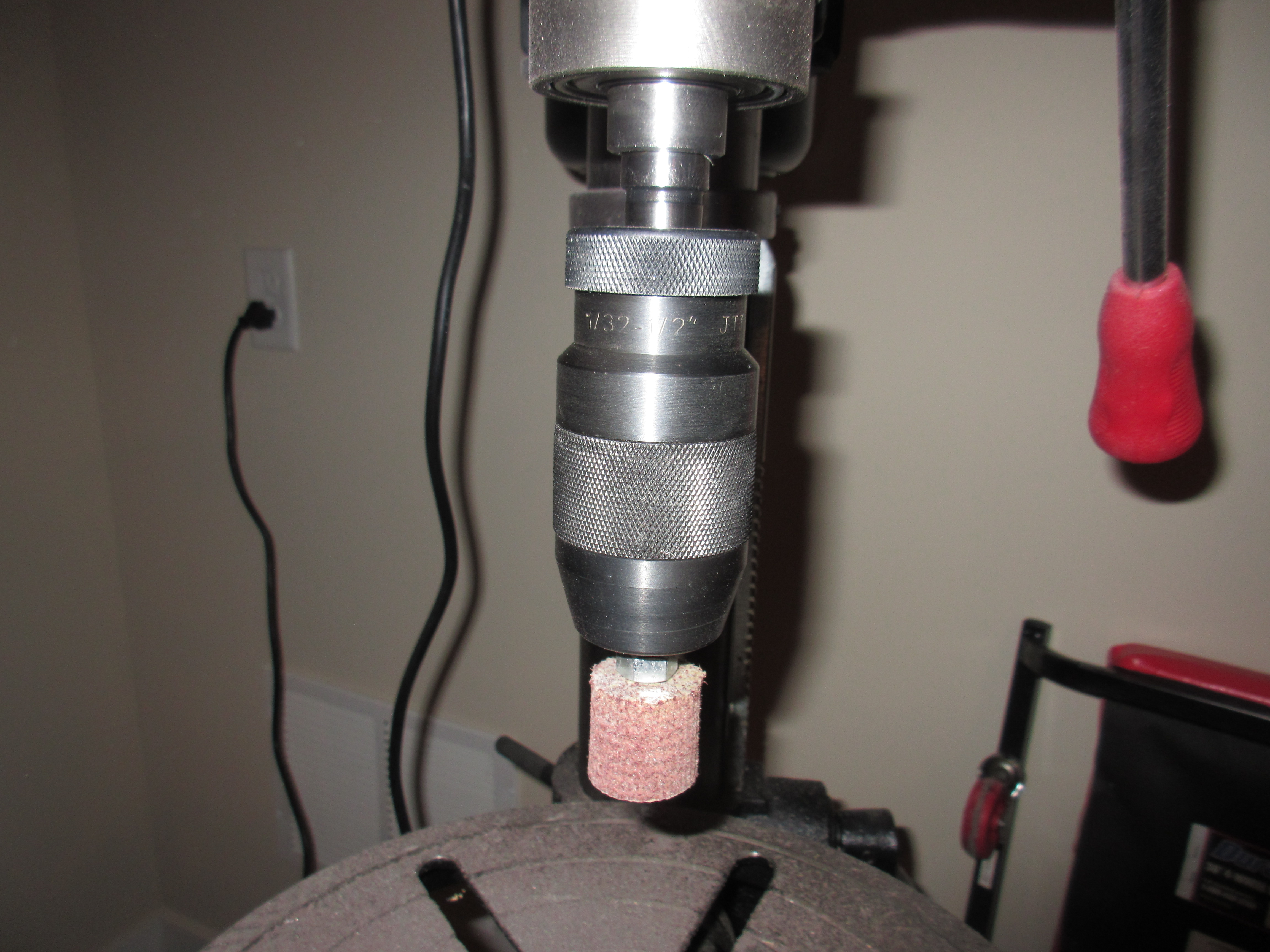
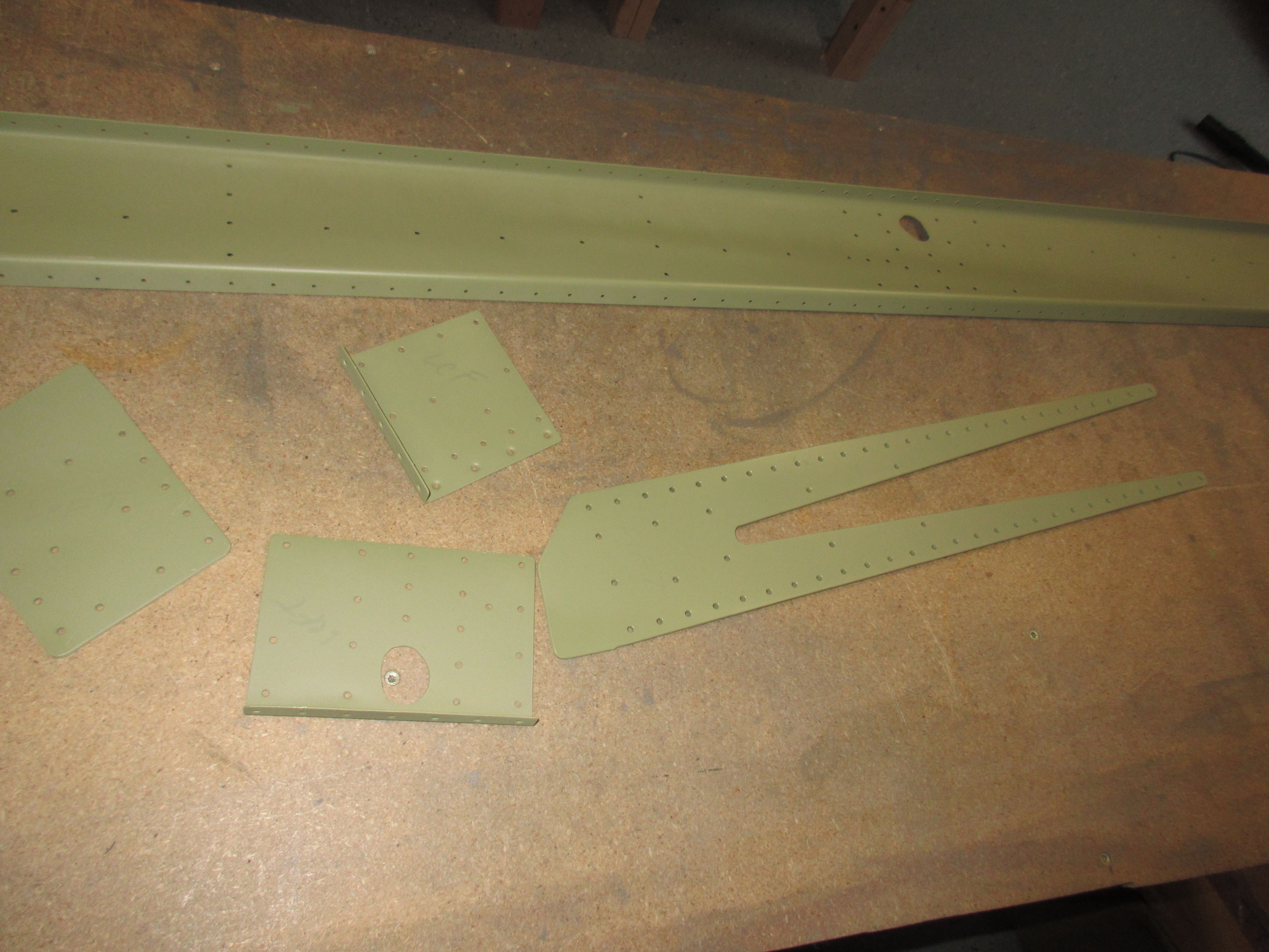
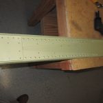
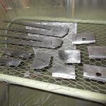
Got a little bit of a late start, I had to run out to Harbor Freight after work to pickup a die grinder for the work tonight, and ran a few other errands, but I managed to put 3.5 hours in, and have the rear spar ready for metal finishing and then priming. I am at the start of the “Assembling the Rear Spar” section of the plans, and the main spars are done for a few more steps.  The session started out by deburring all the edges of the rear spar parts: W-707A rear spar channel, W-707E and W-707F doubler plates, W707G reinforcement fork and the W-707D rear spar doubler. I deburred the edges using the scotchbrite wheel, which made quick work of the parts, even the long rear spar channels.

Then, Vans has us trim away a decent chunk of the W707G and W707D doublers since this is an RV-7.  I studied the plans for a bit and then made the careful measurements, and marked the lines.  Stupid me forgot to take photos of my marks before I made my cuts, so I don’t have a good way to show how I did it, but here is the part of the plans that gives the cut dimensions:

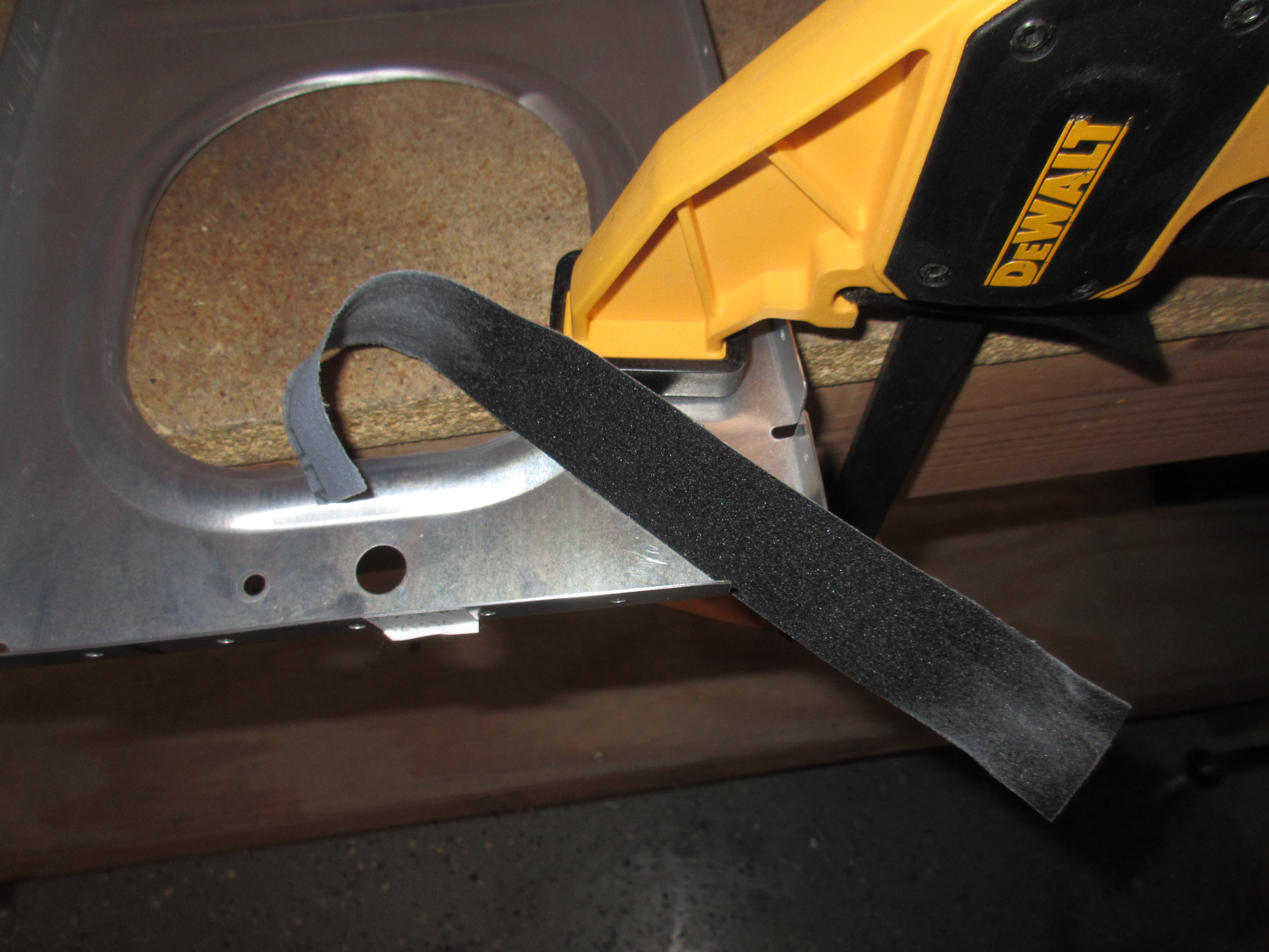
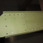
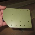
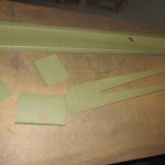
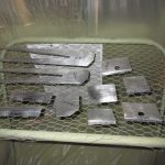
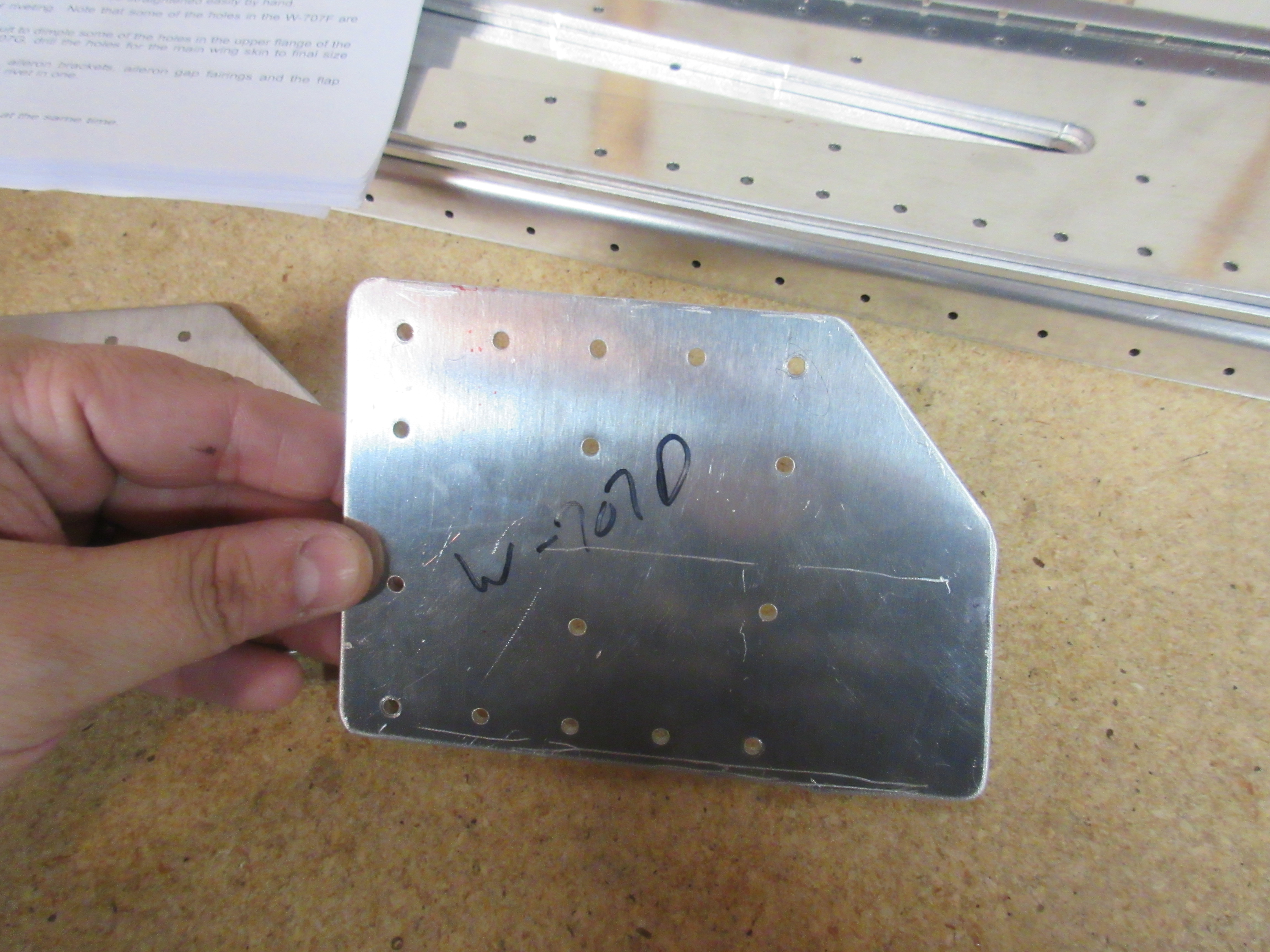
I first decided to cut the W-707D Rear Spar Doubler first, since it would be cheap and easy to ship in case I messed it up. Note how the shaded part is angled a bit and there are 4 measurements I had to make and then mark.  Once I had my marks made, I connected the marks with a straight line using a machinists ruler. After confirming everything was right, I decided to cut it using my bandsaw with a metal blade.  This is thick aluminum, so snips was not an option and I figured I would cut with the bandsaw and then grind away any odd cuts or un-eveness from the saw.  It actually turned out really nice, and only needed a very small amount of grinding!

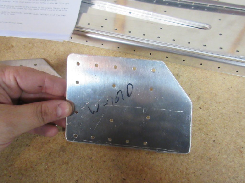
Once I had this piece looking right, I used it as a template for the others.  I have to make this same cut on the W-707D for both sides, as well as the W-707G reinforcement forks for both sides.  I just cleco’d the freshly cut doubler against the other pieces, and marked the edge with a sharpie, and cut them on the bandsaw.  After grinding the edges and deburring them to a smooth edge on the scotchbrite wheel, they were done.

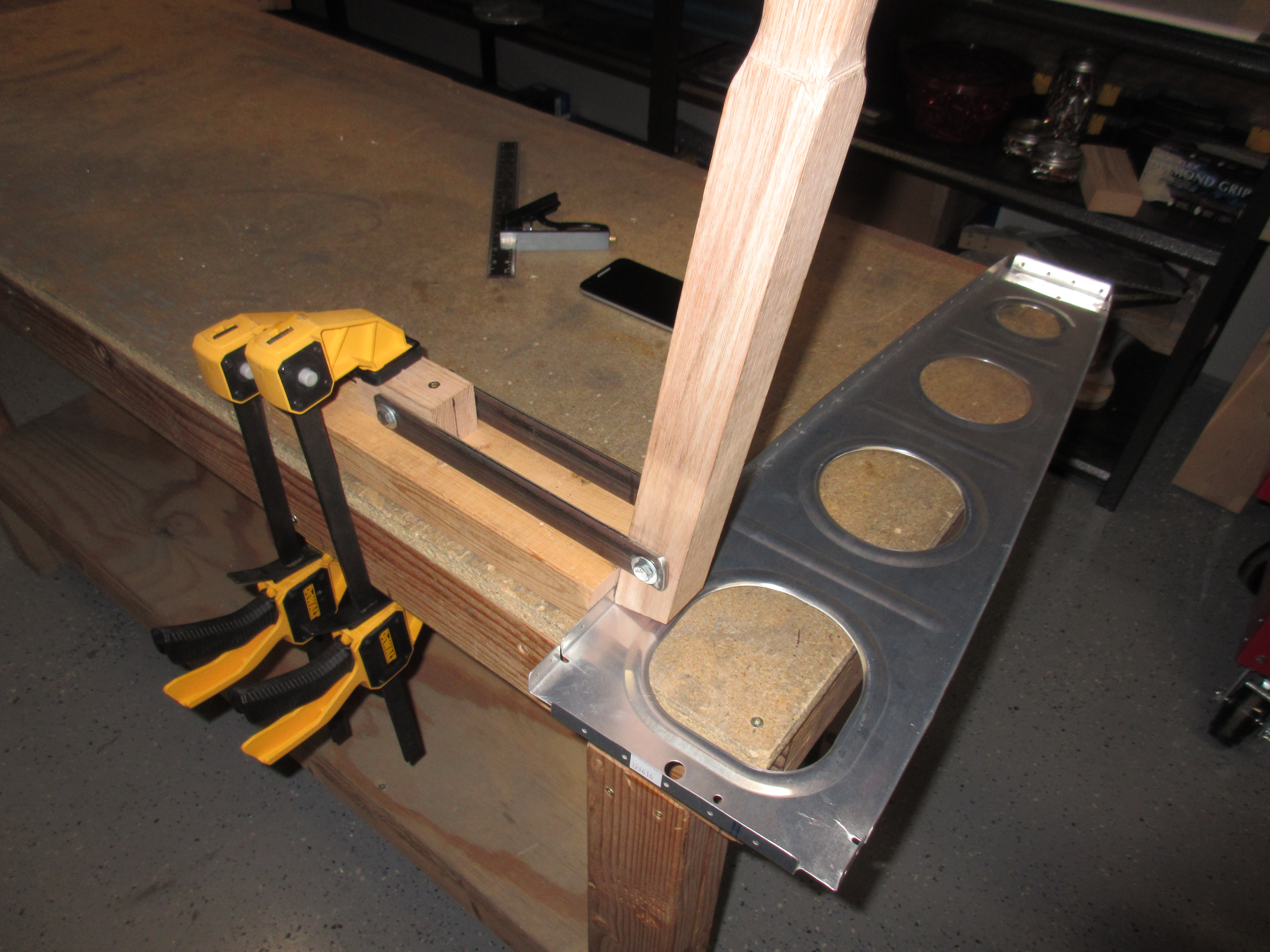
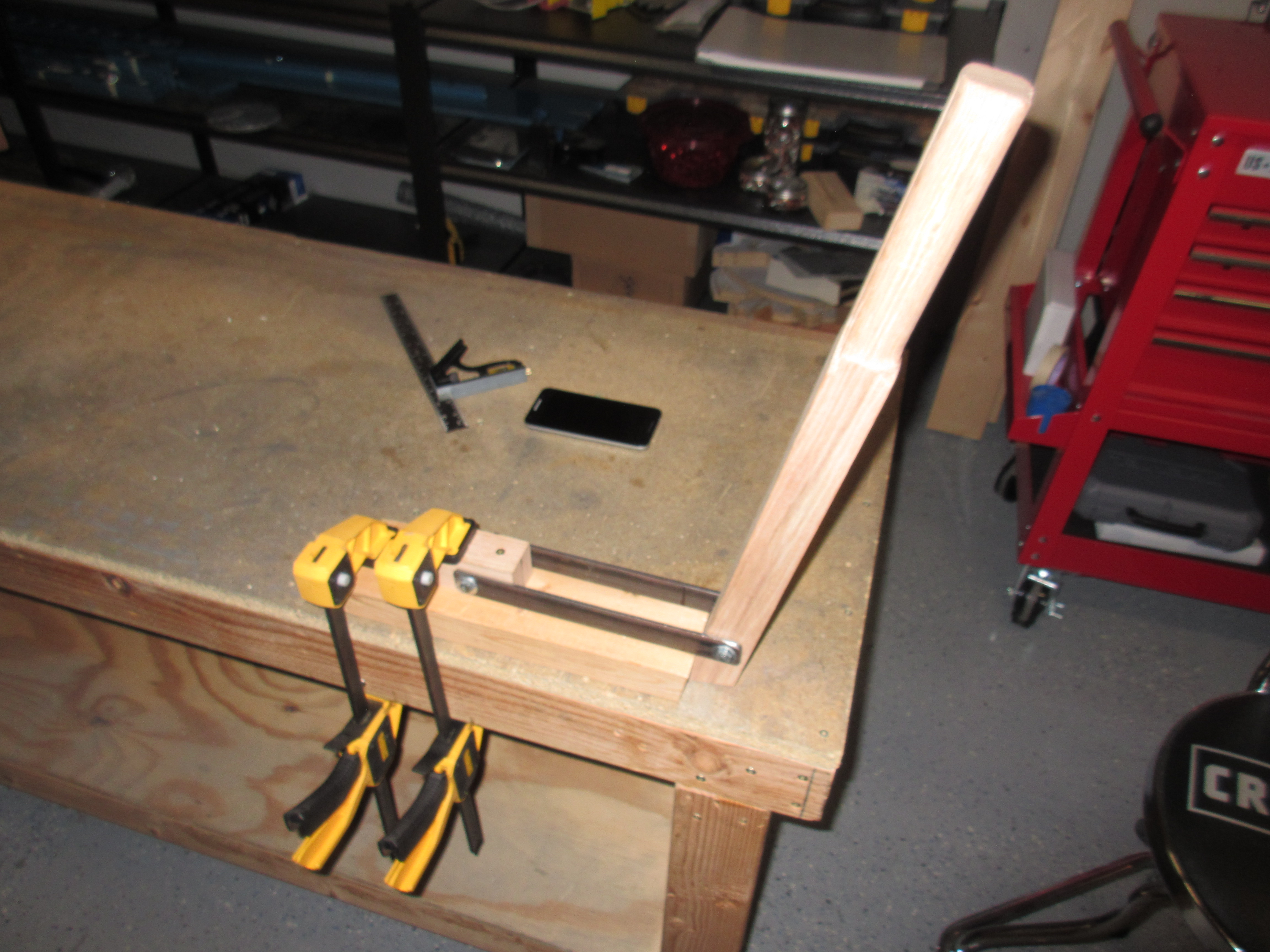
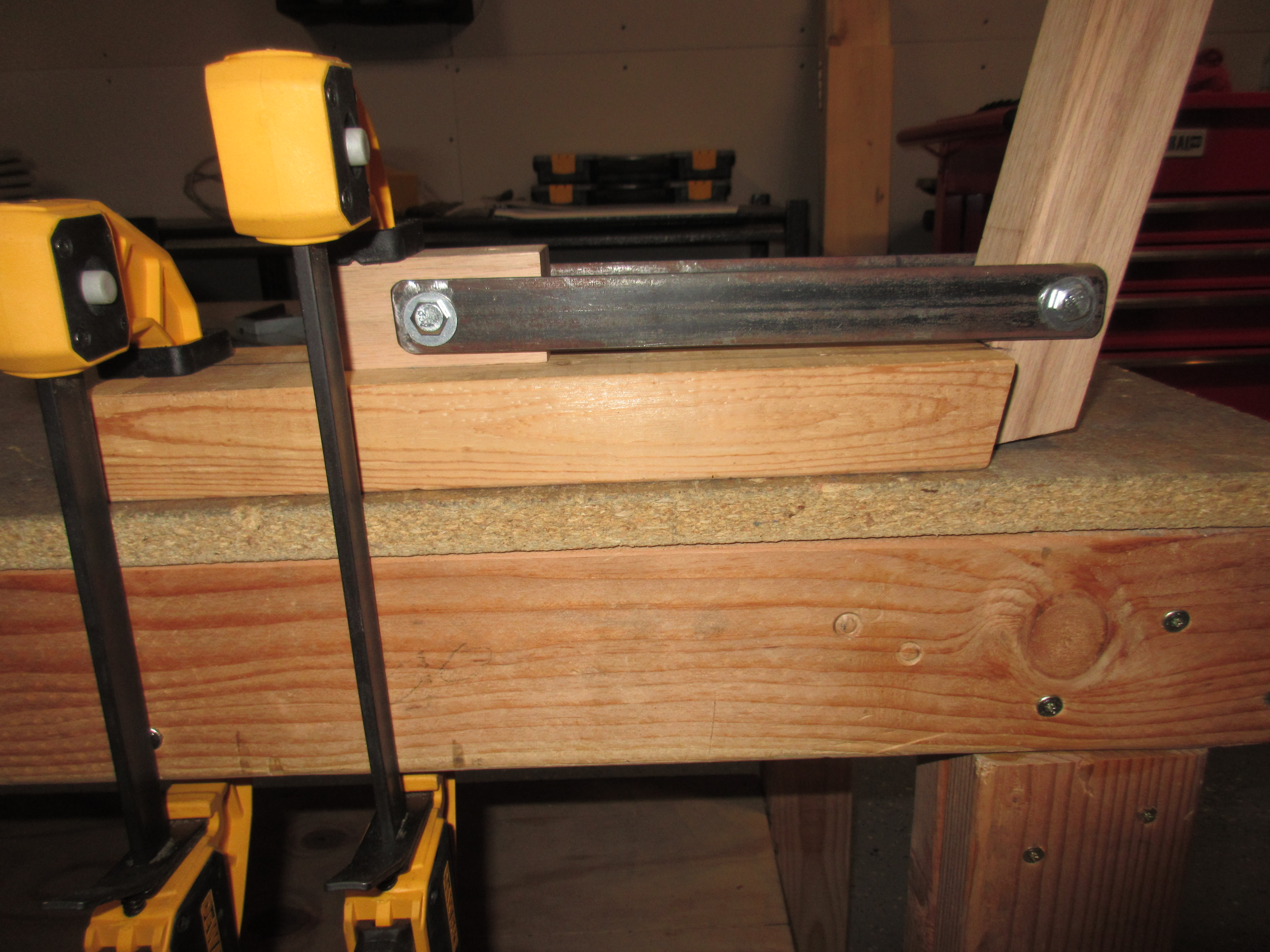
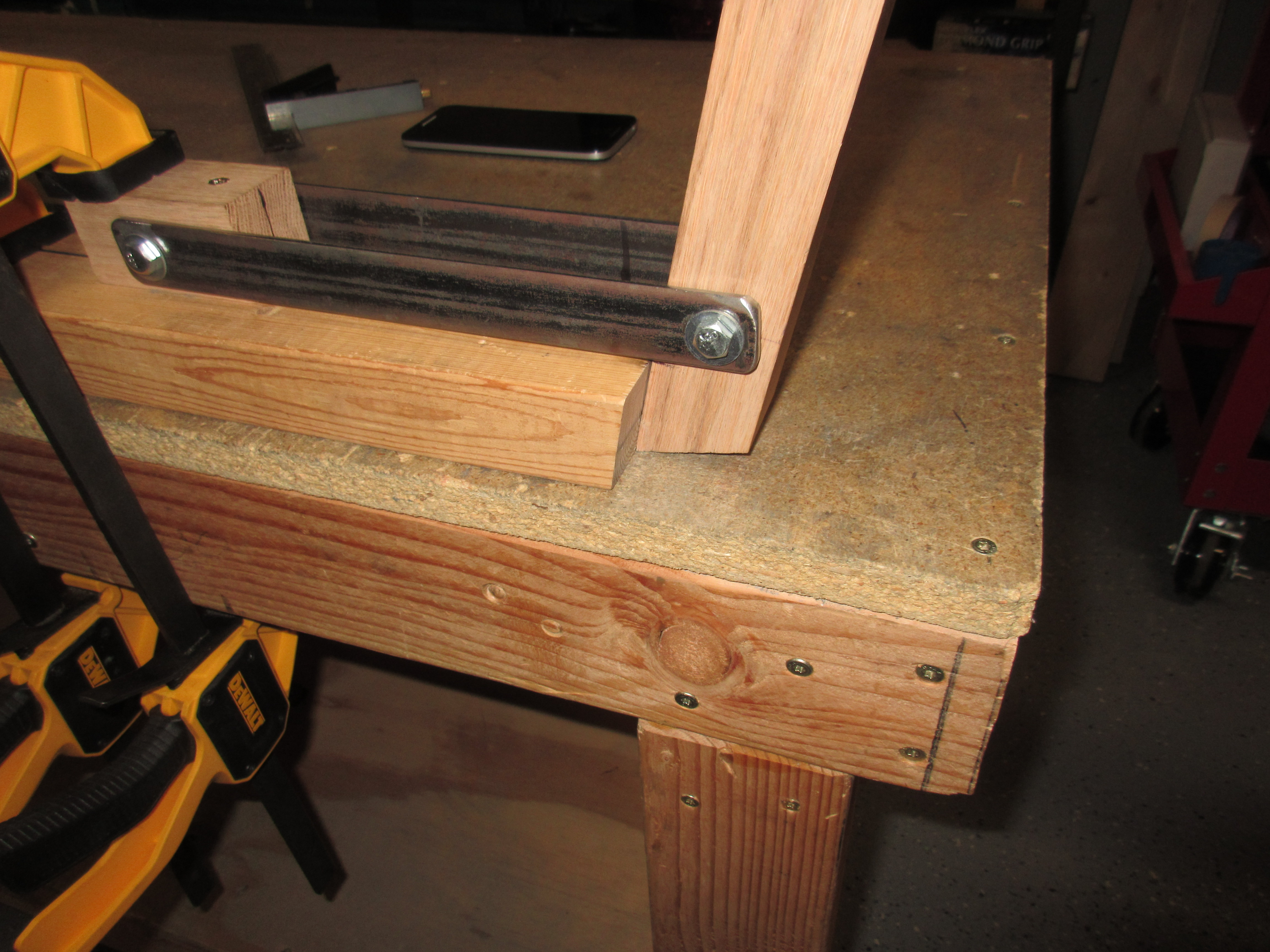
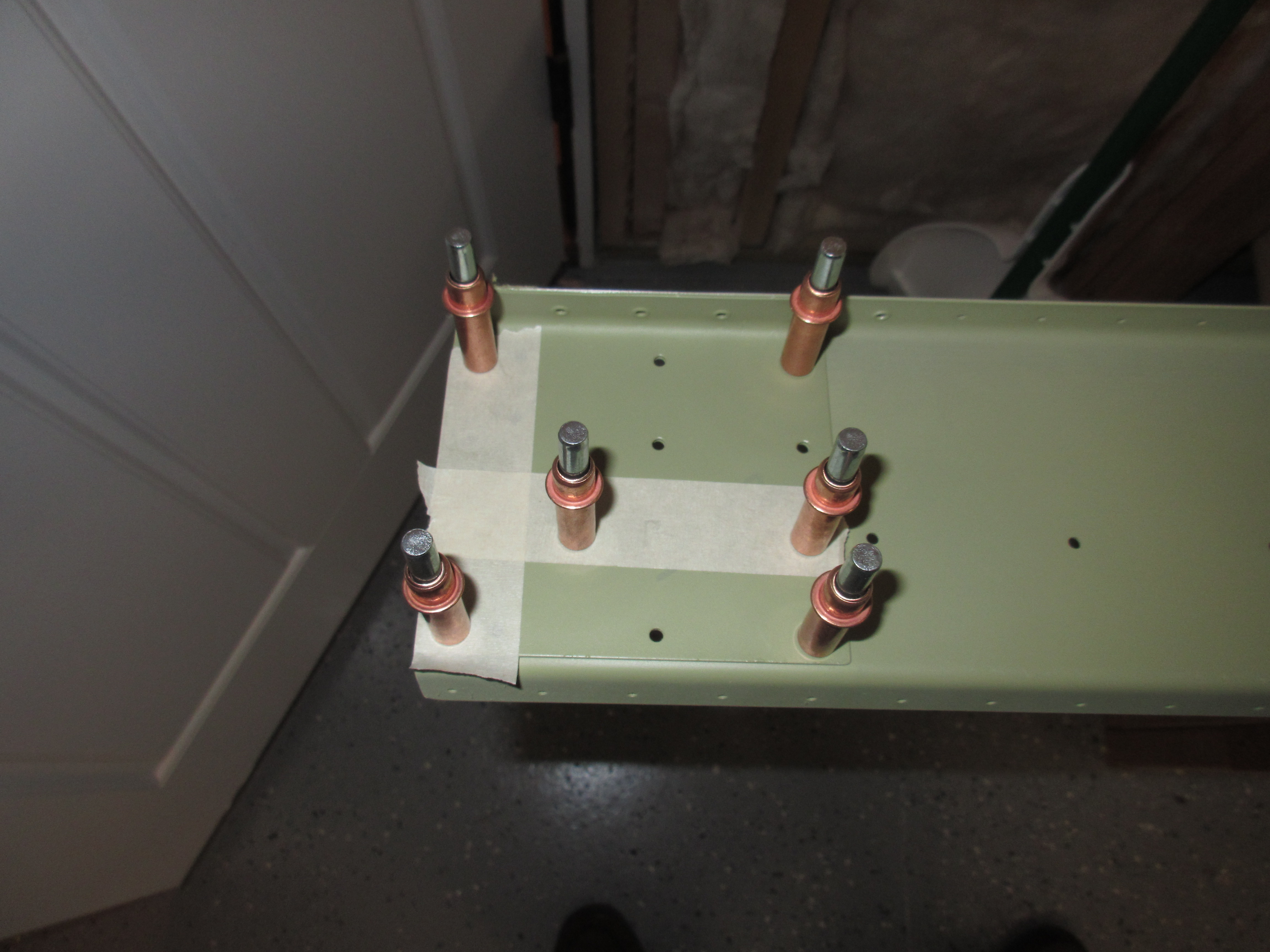
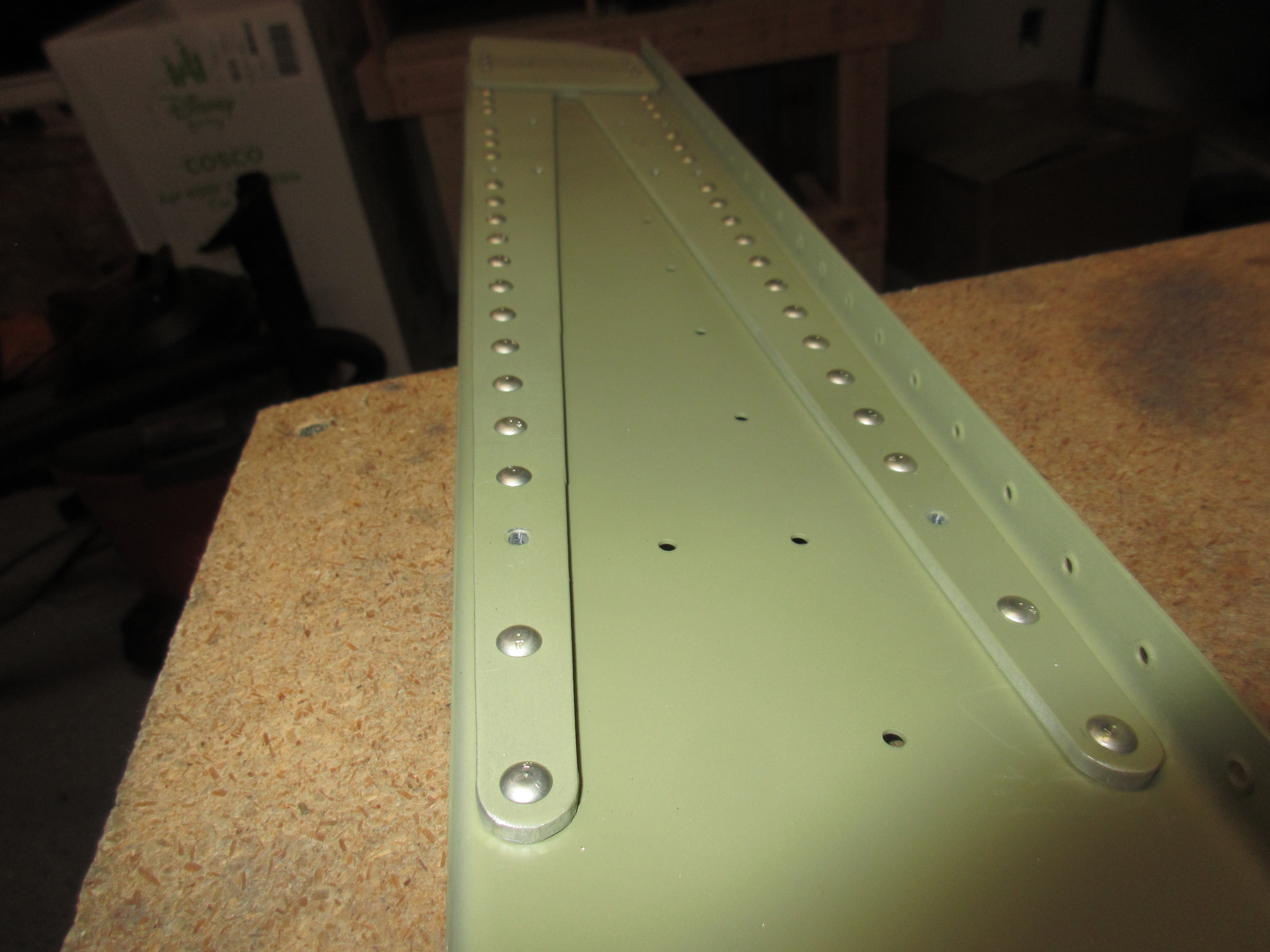
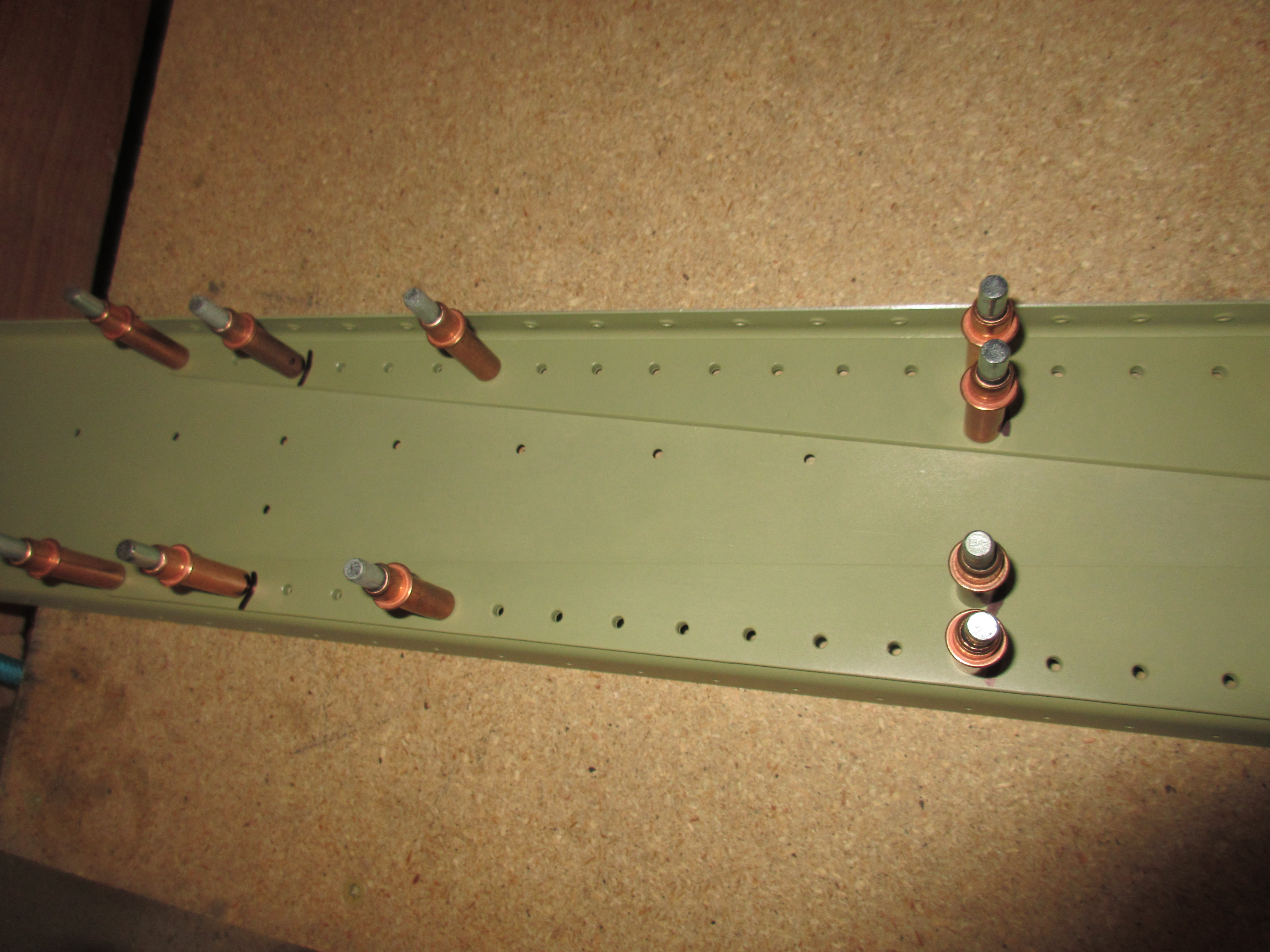
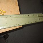
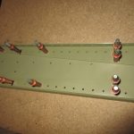
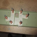
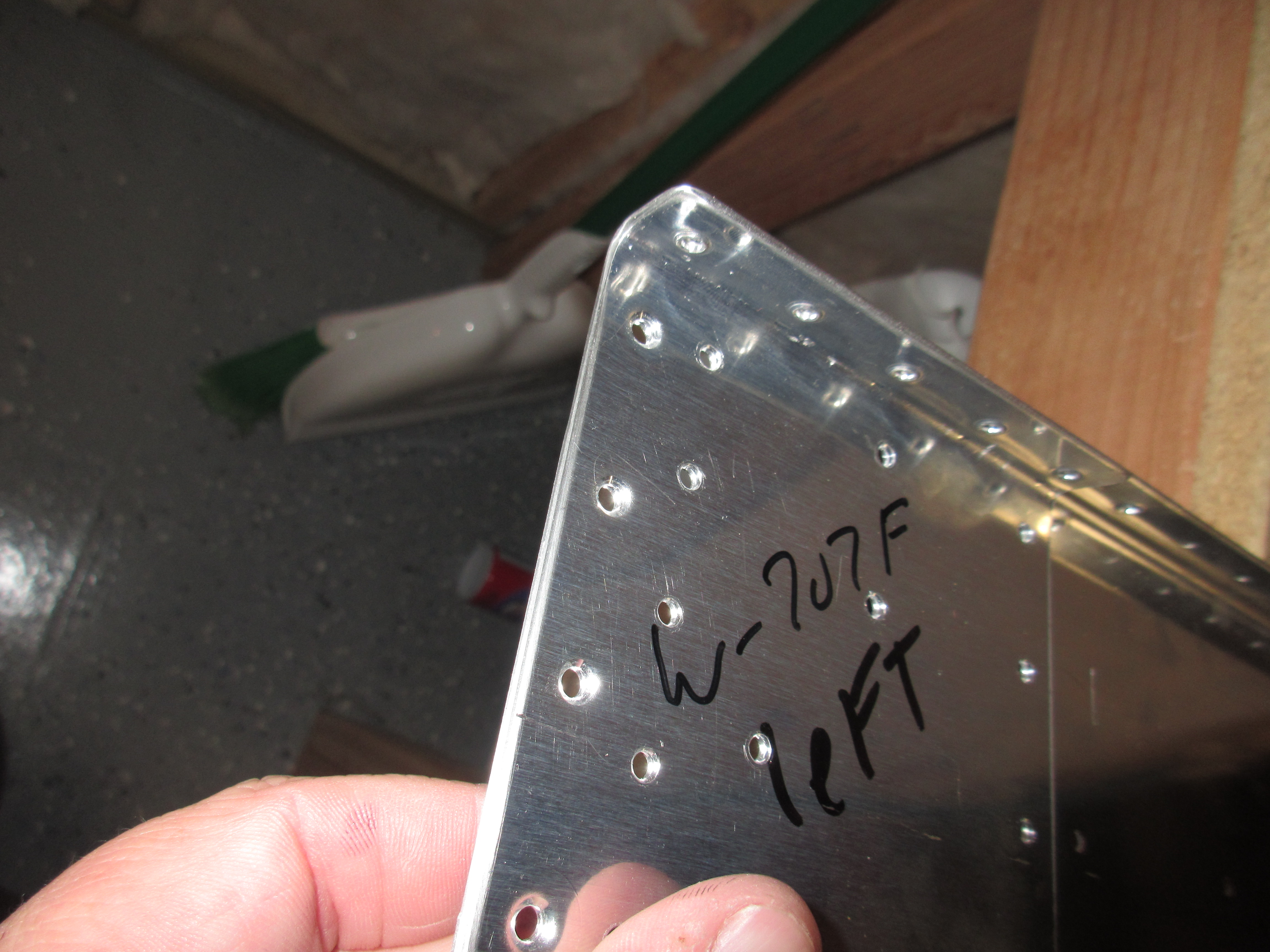
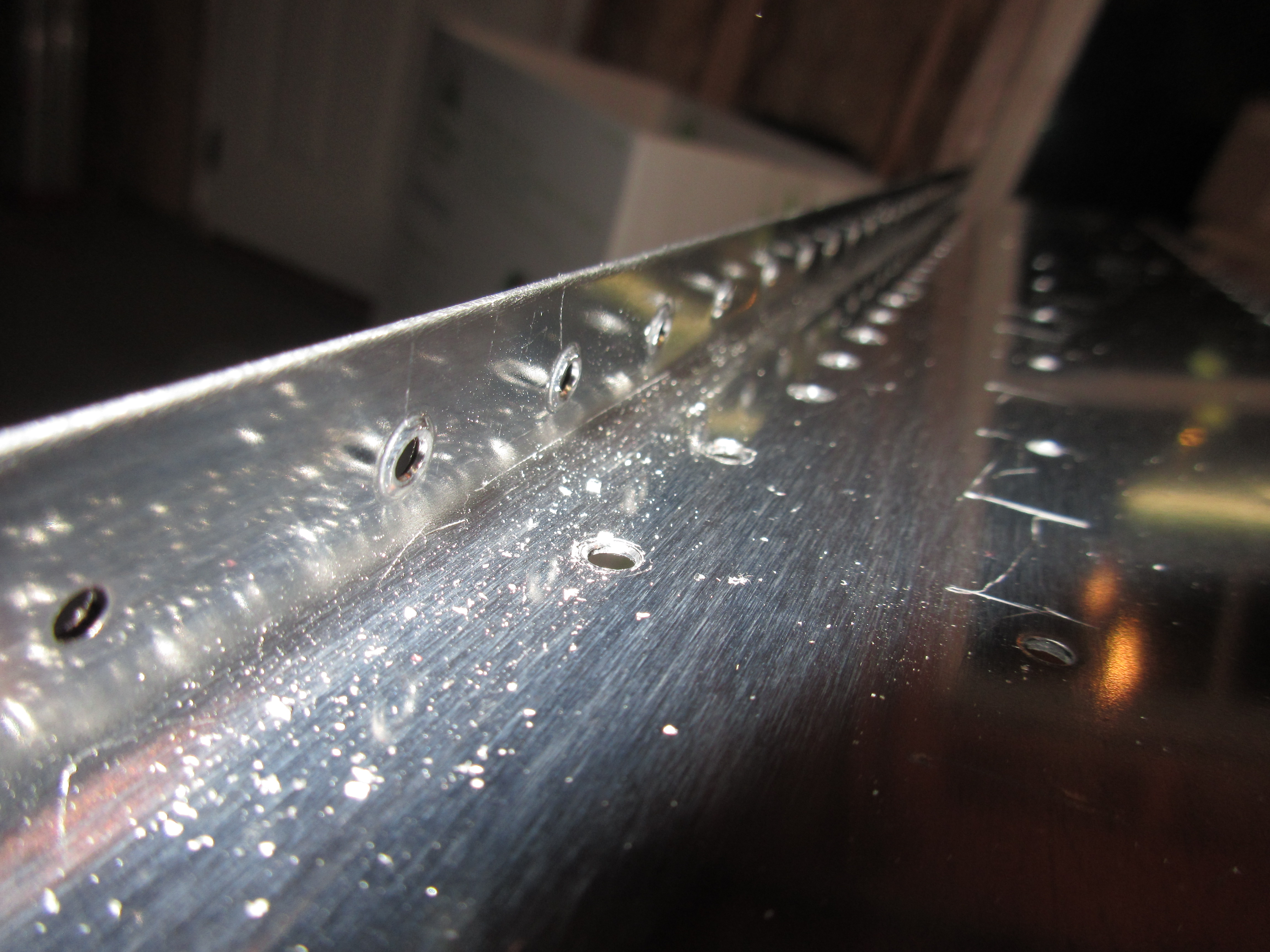
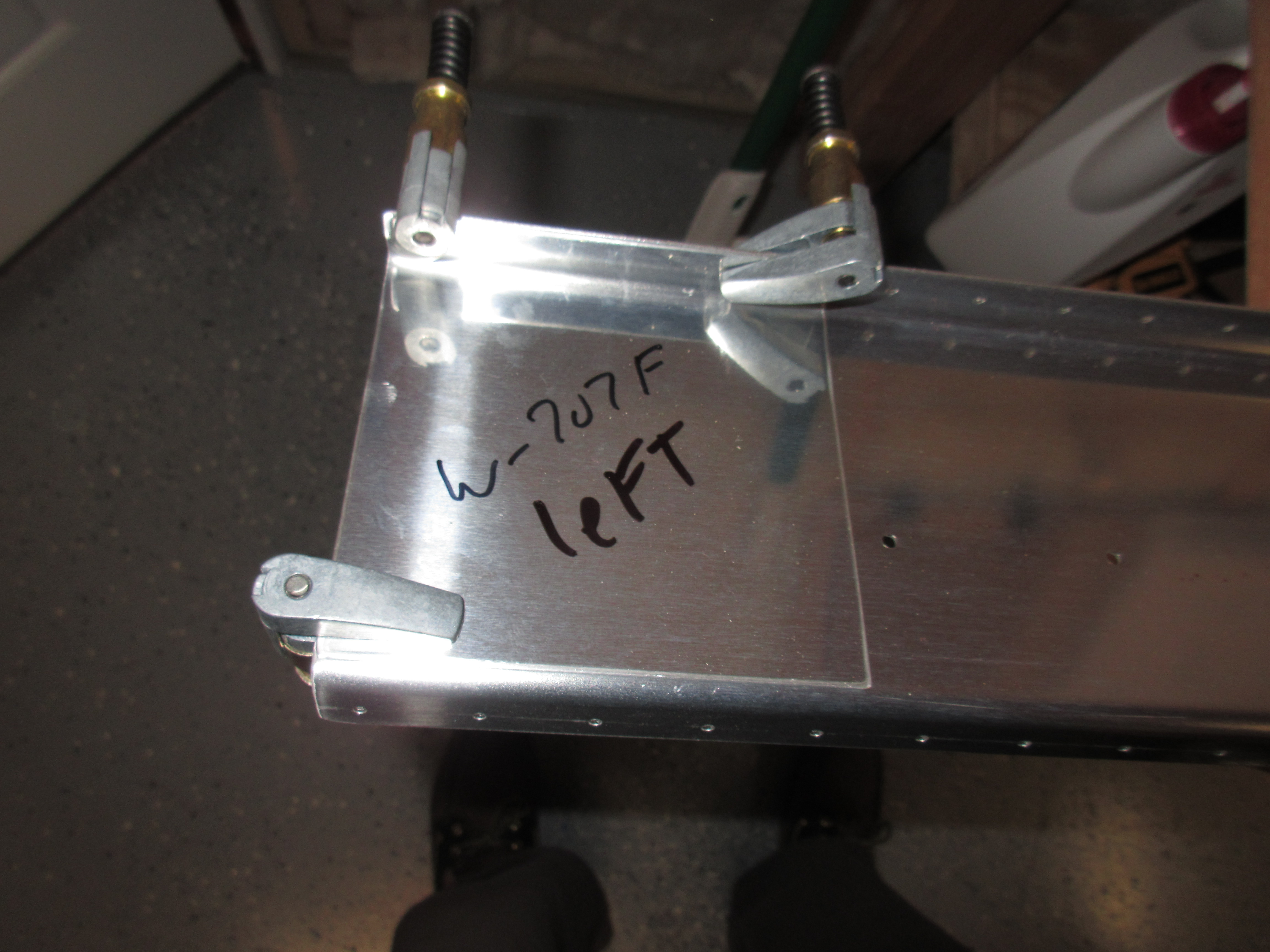
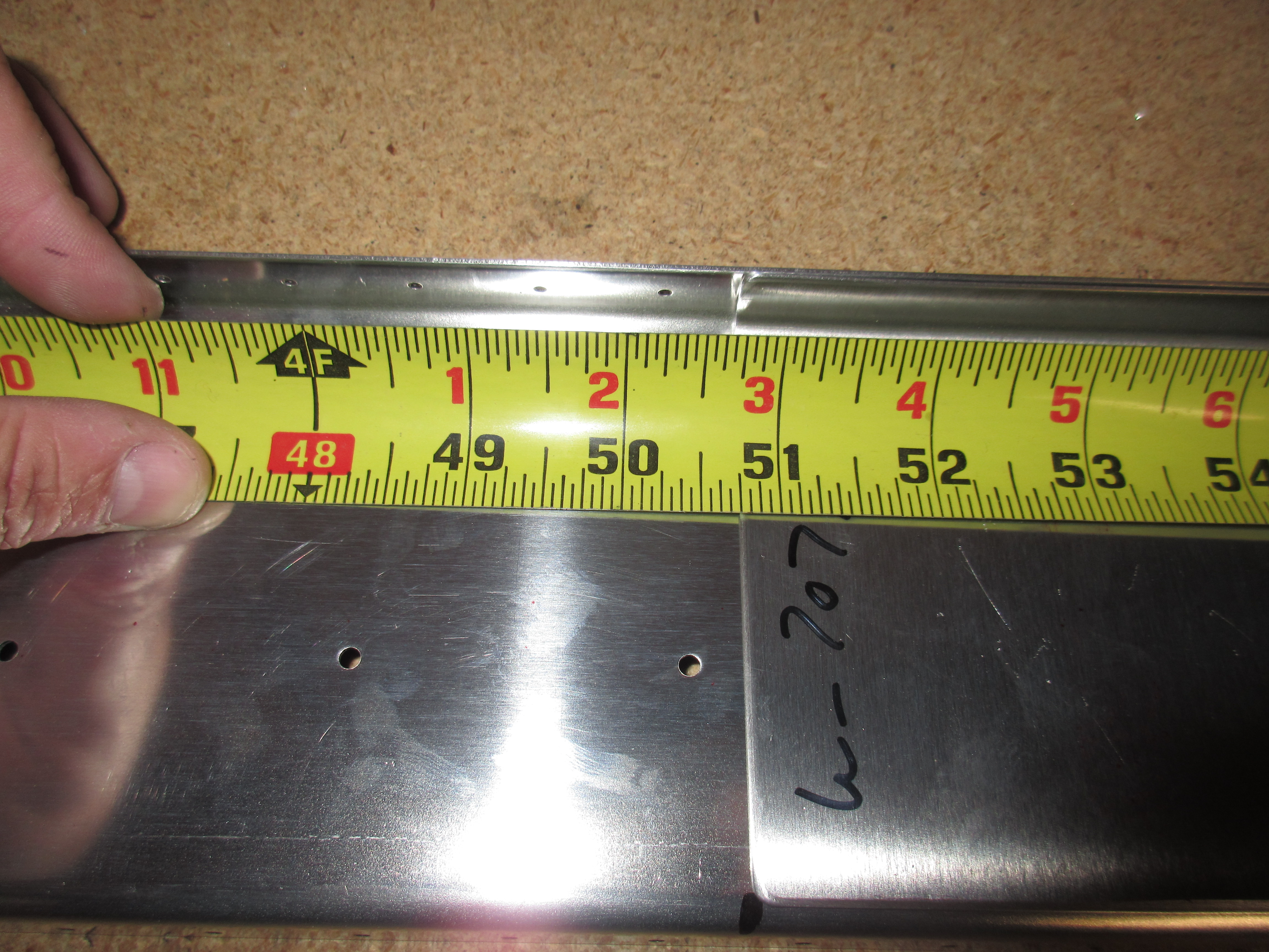
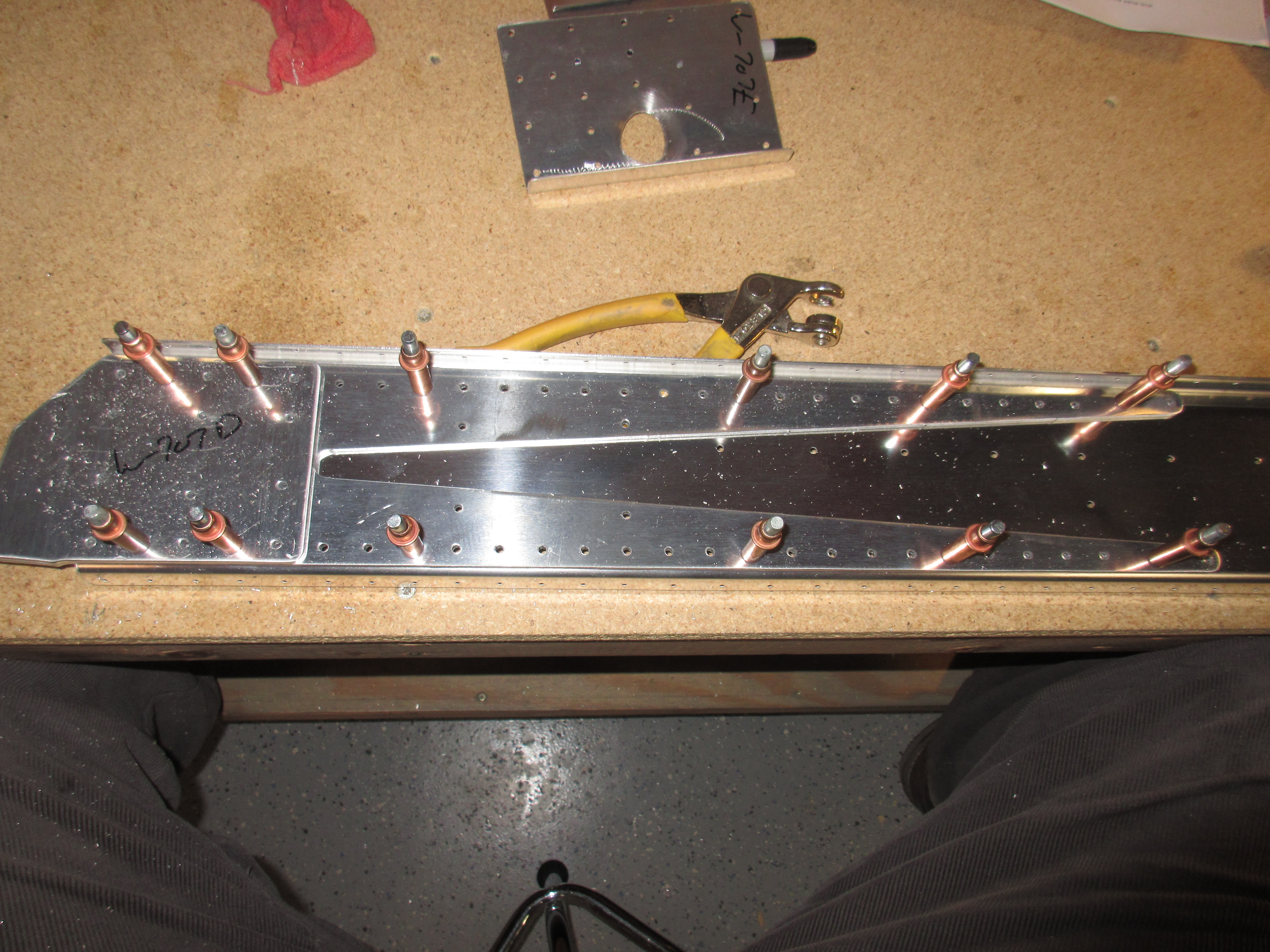
Now that I have all my rear spar parts deburred, trimmed and ready to go, its time to start assembling and drilling both rear spars. I clamped W-707E and W-707F doublers into their locations. W707F was pretty easy, since it mounts flush against the most outboard edge.  The W-707E needed some measuring.  The plans calls out to place the most outboard edge of the doubler 50 and 3/4″ from the outboard edge of the rear spar channel.  Once they were both in place, I clamped them down with side clamps and then match drilled all the holes to a #30 after double checking all the rivet sizes in the plans.

This is the easy one!

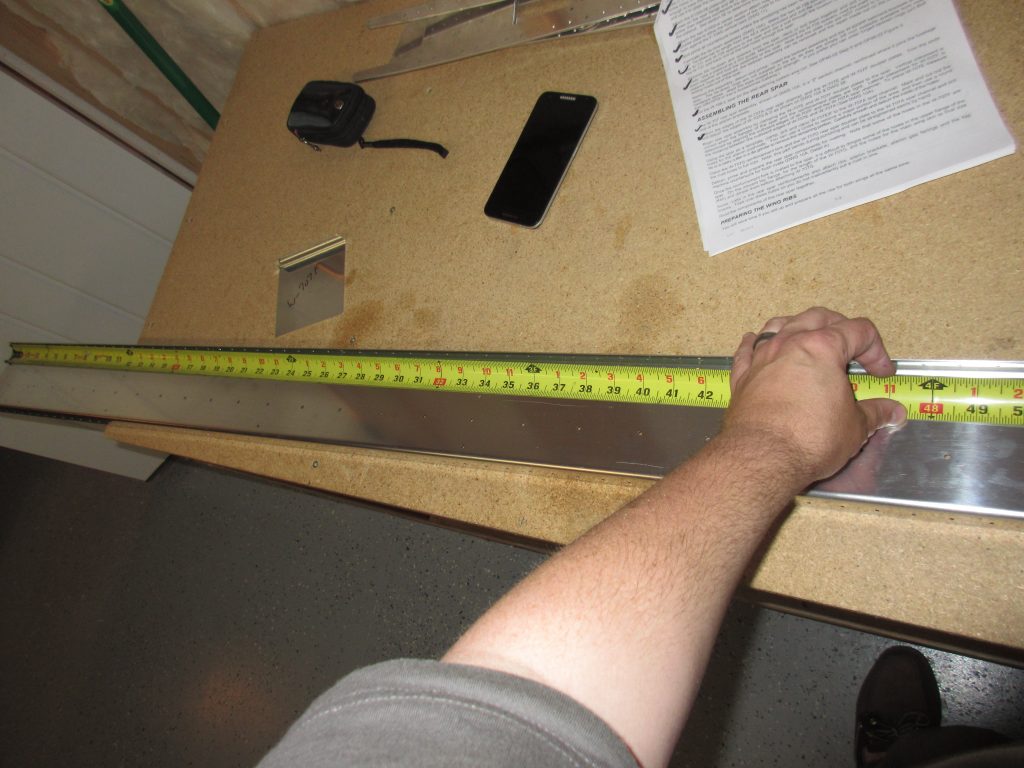
Measuring for 50 and 3/4″

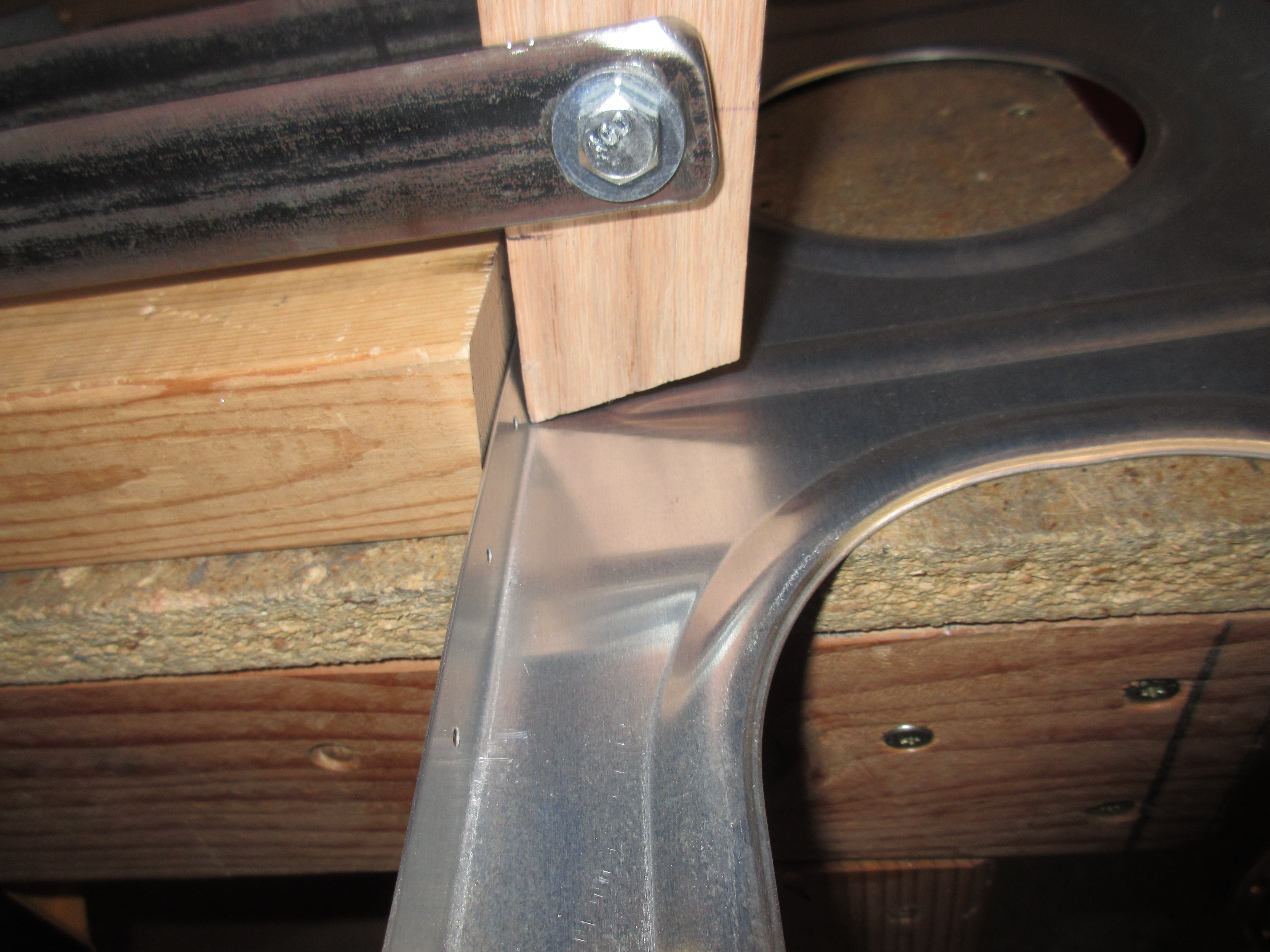
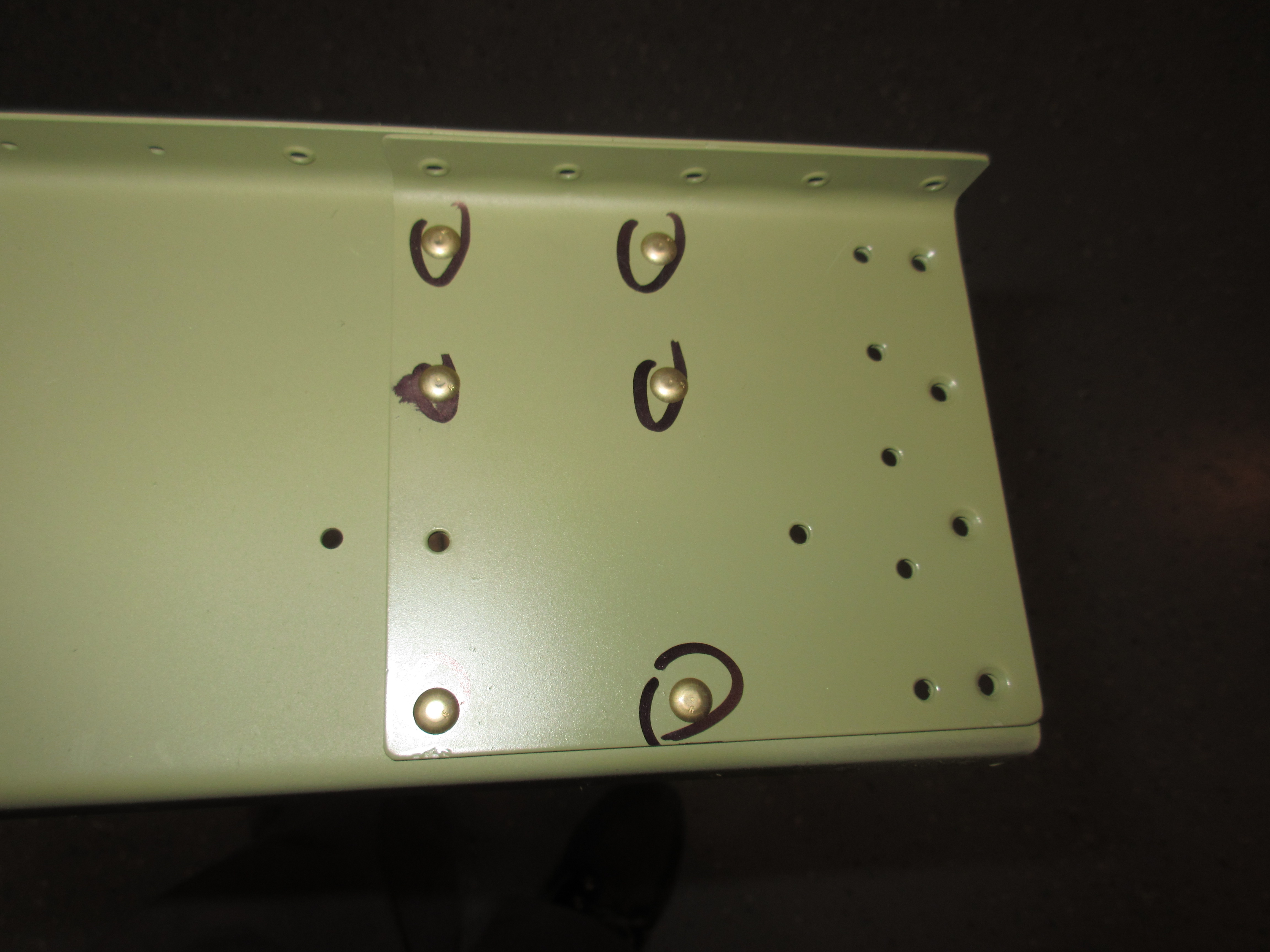
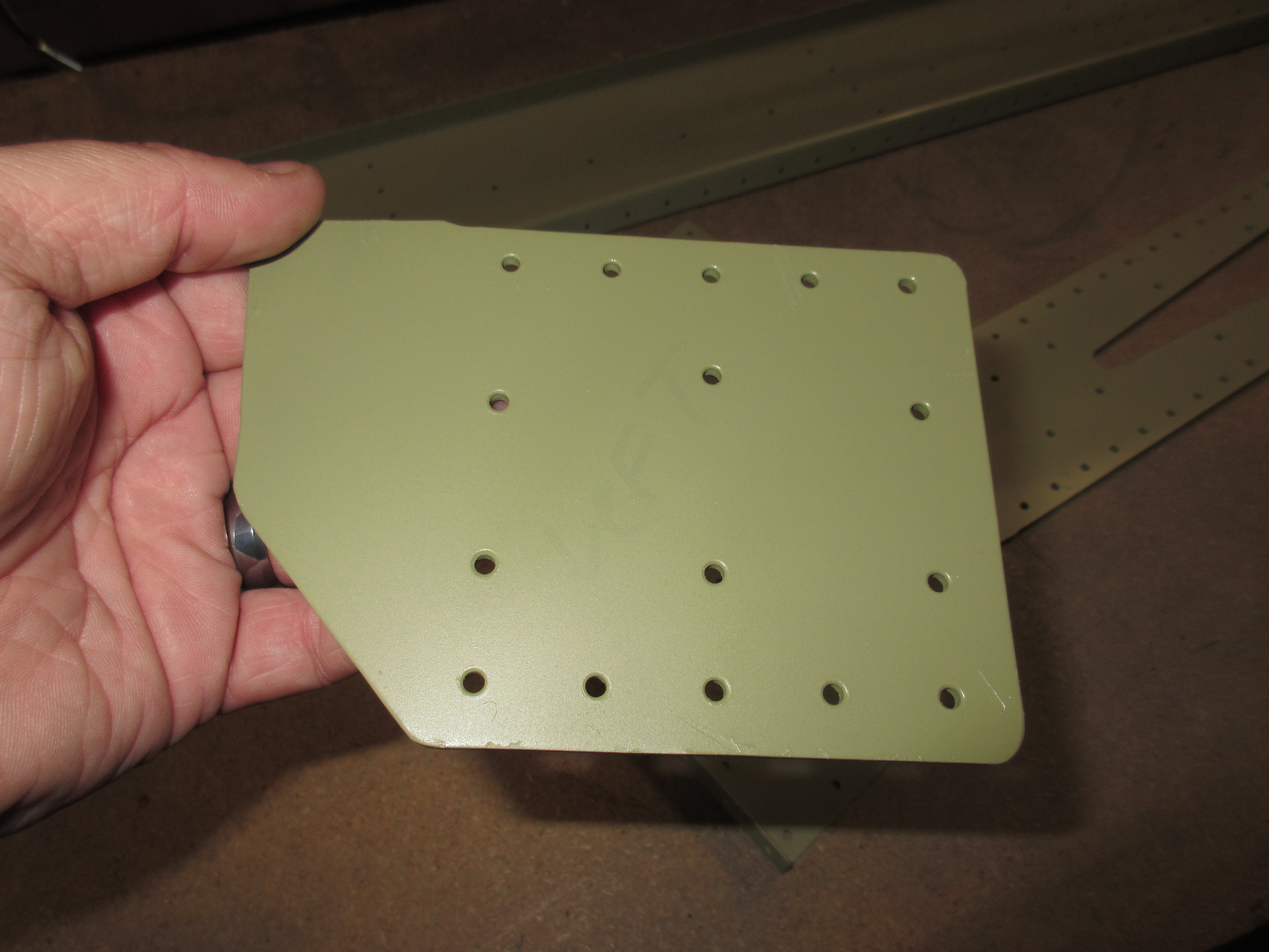
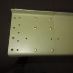
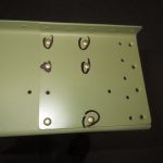
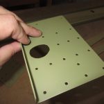
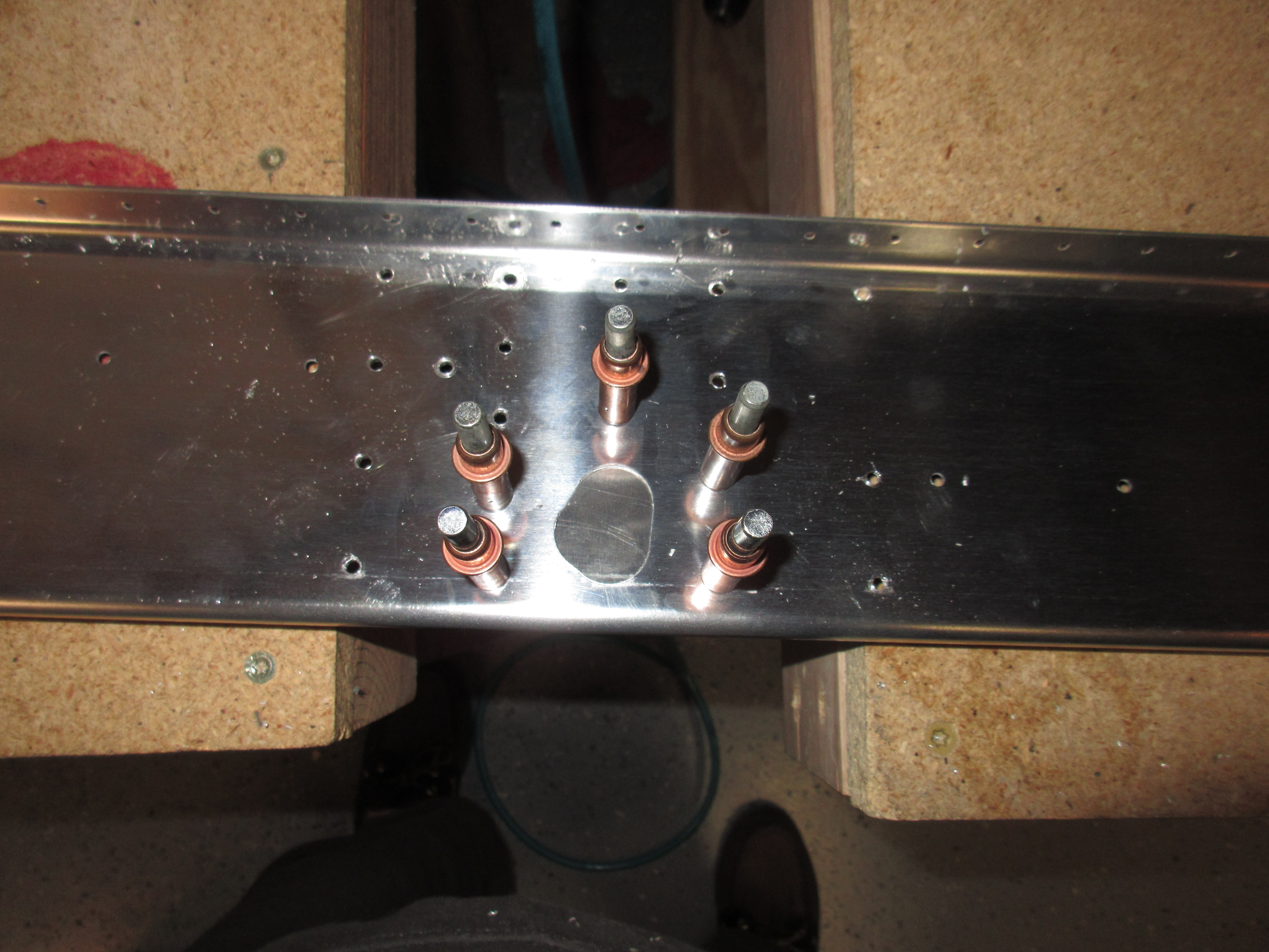
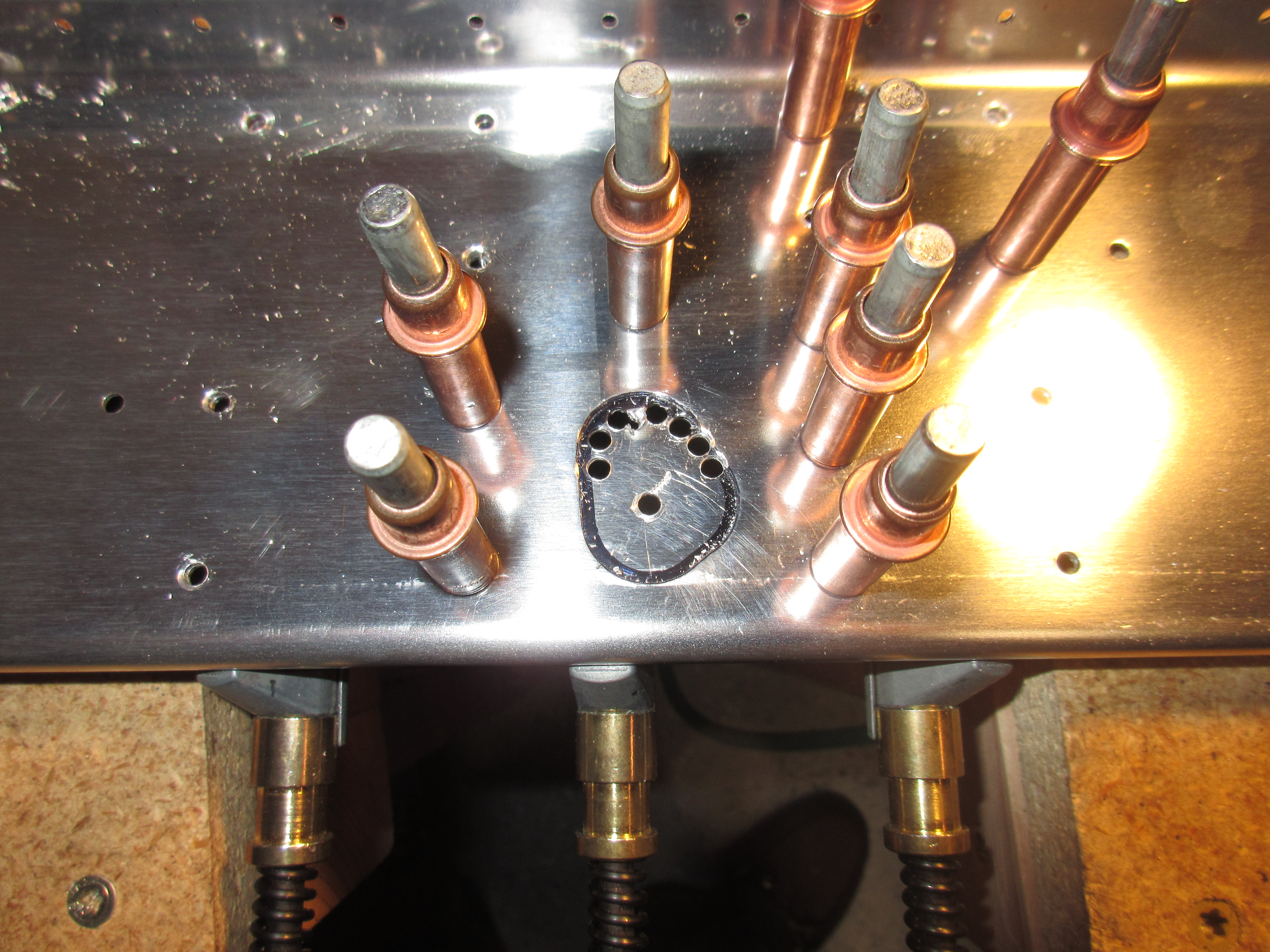
Once I had all the rivet holes drilled to size, the next step is to cut out the hole for the aileron pushrod in the doubler plate.  I flipped the rear spar over, and use the pre-punched hole in the spar to mark the location for to transfer the hole to the doubler plate.

Then, I used a unibit to drill out the largest section of this hole, and used a #40 drill bit to drill out the smaller section.  This is to get everything started so I can file, grind and trim it the rest of the way.

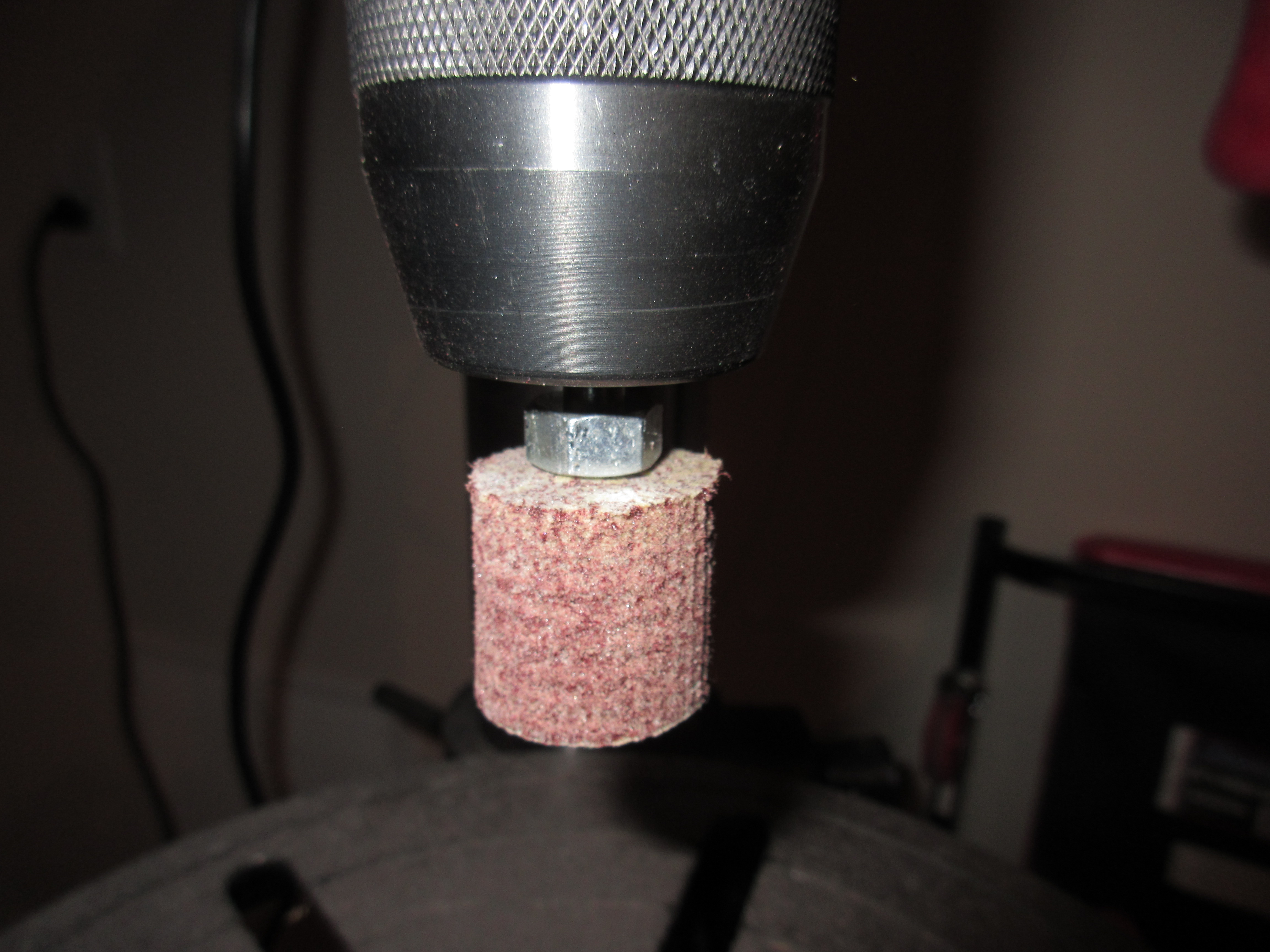
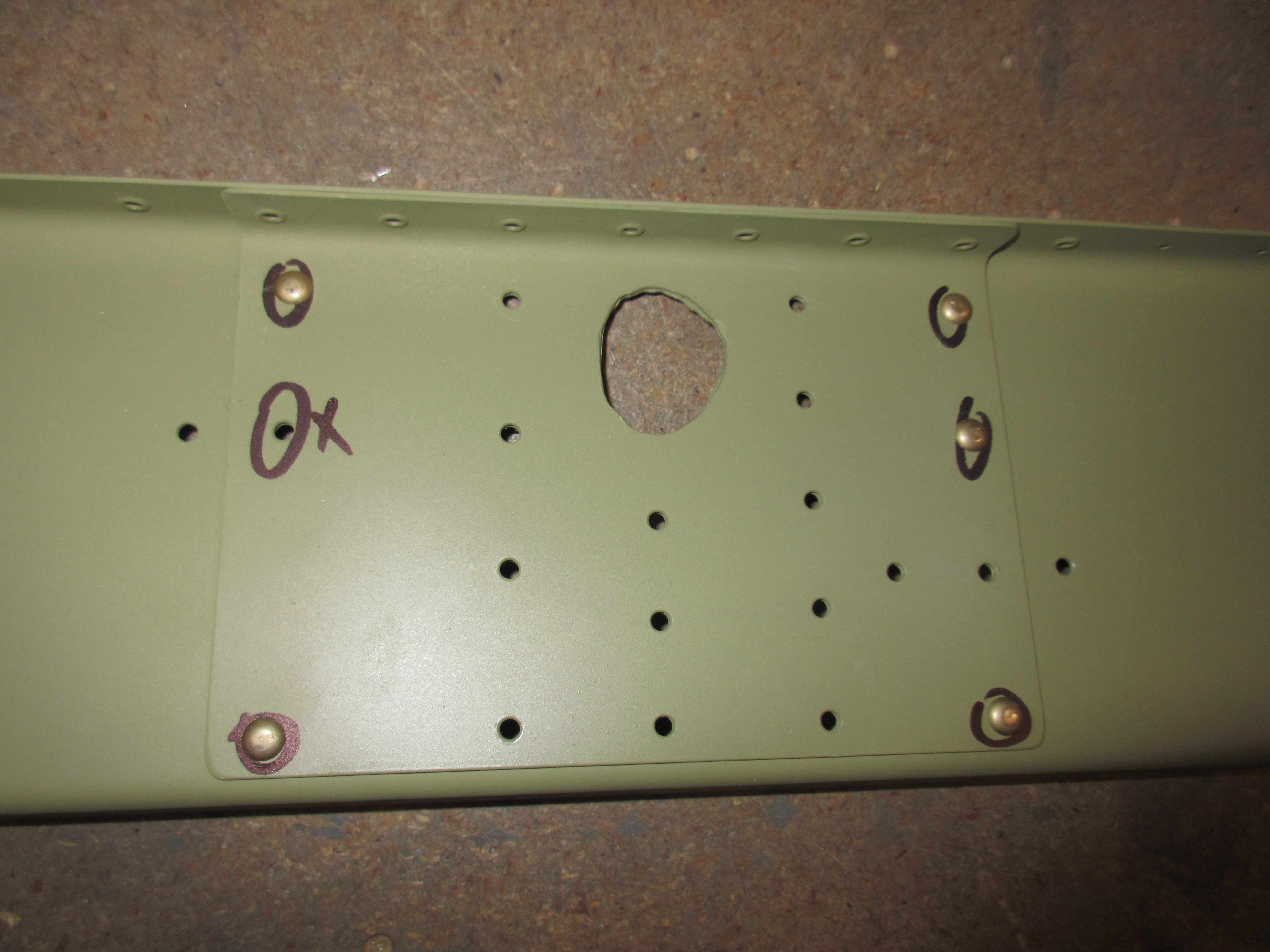
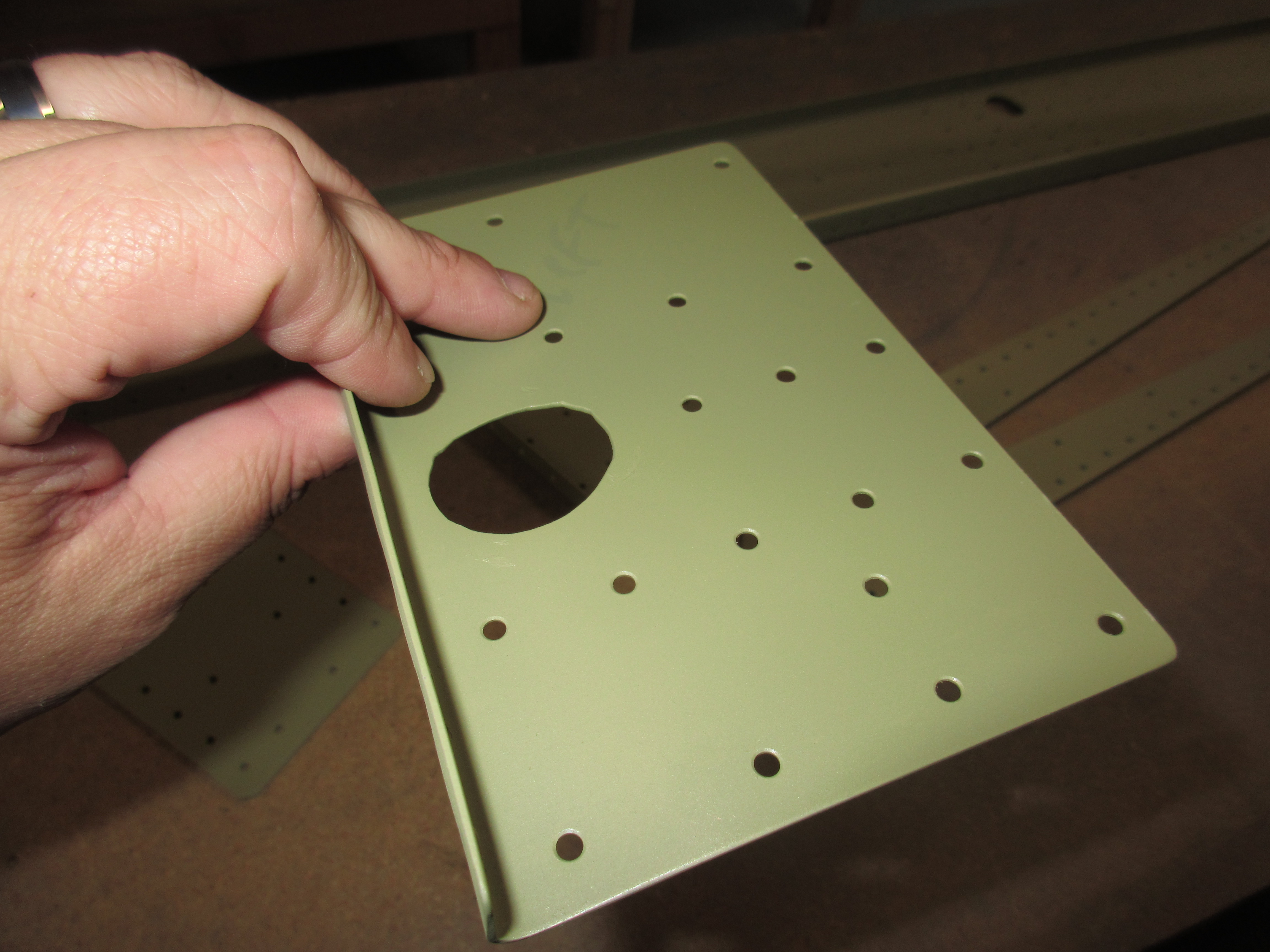
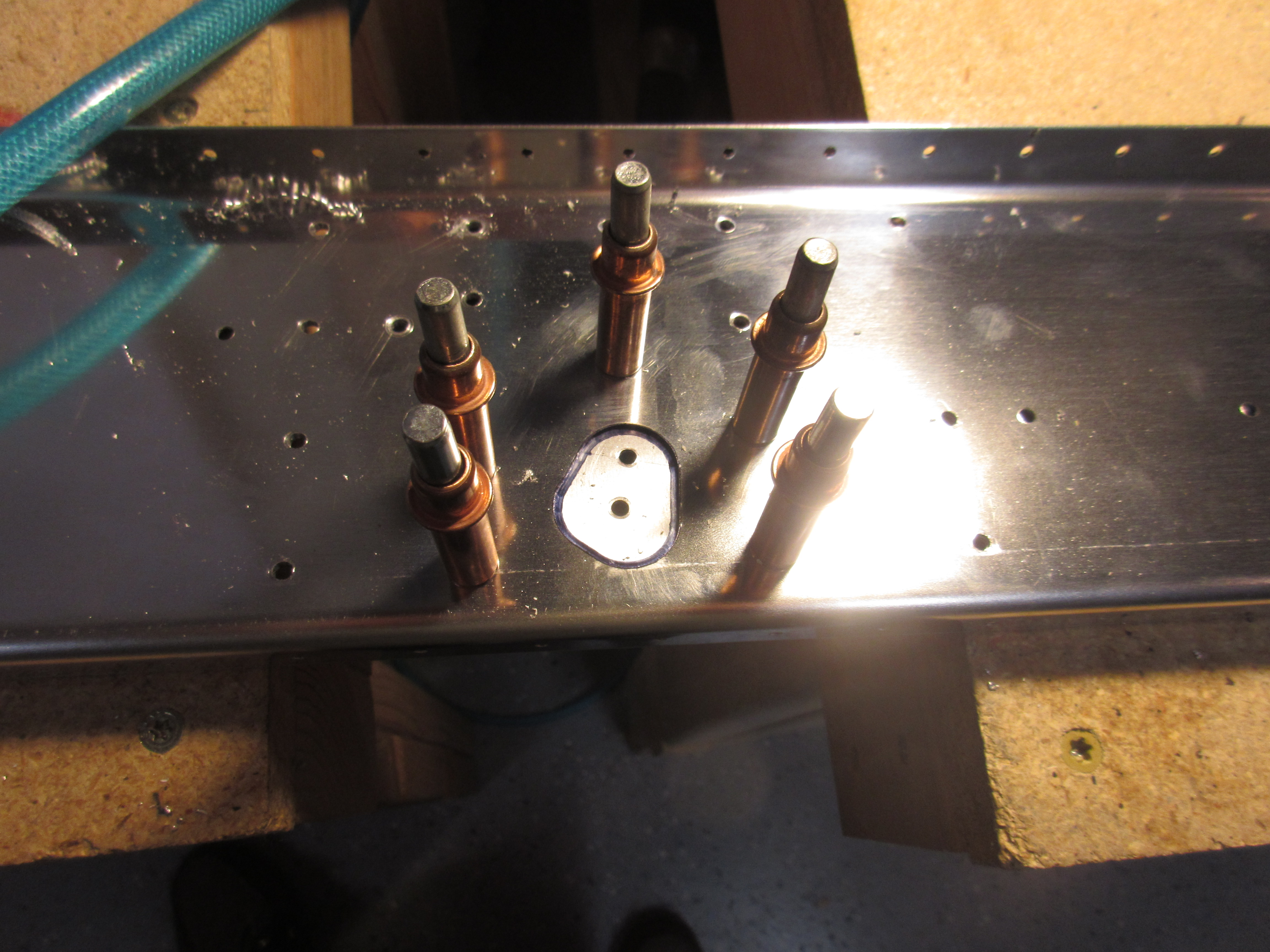
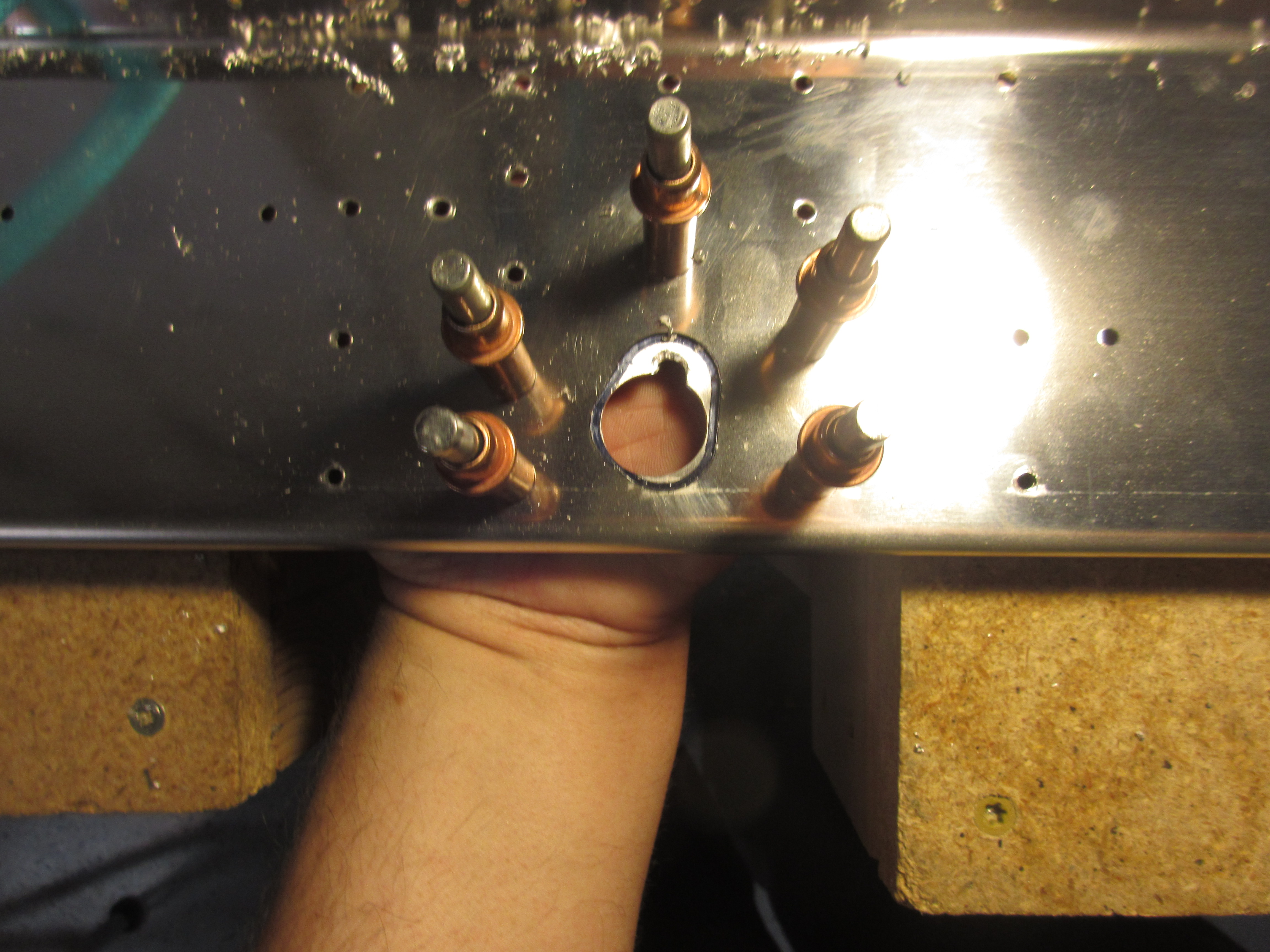
Once I had the holes to about close as I could get (notice there is still some black sharpie lines to be trimmed out in the photo above), I removed the double and used a combination of files (round, and flat of different sizes) and then fired up the die grind with a small grinding wheel to grind down what remained of the metal.  I then finsihed up the holes with a scothbrite pad to remove any burrs that may have been left behind. I am pretty happy with how they turned out.  They are slightly larger than the hole in the rear spar, but I think that’s fine.

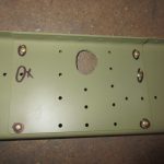
Next up was to just repeat these same steps on the right wings rear spar.  I did the aileron hole a little different, but drilling even more #40 holes to make the grinding and filing go a little quicker which seemed to have help cut down on the time it took. I still used the unitbit in the larger middle-ish section which removed about 97% of the metal I needed.

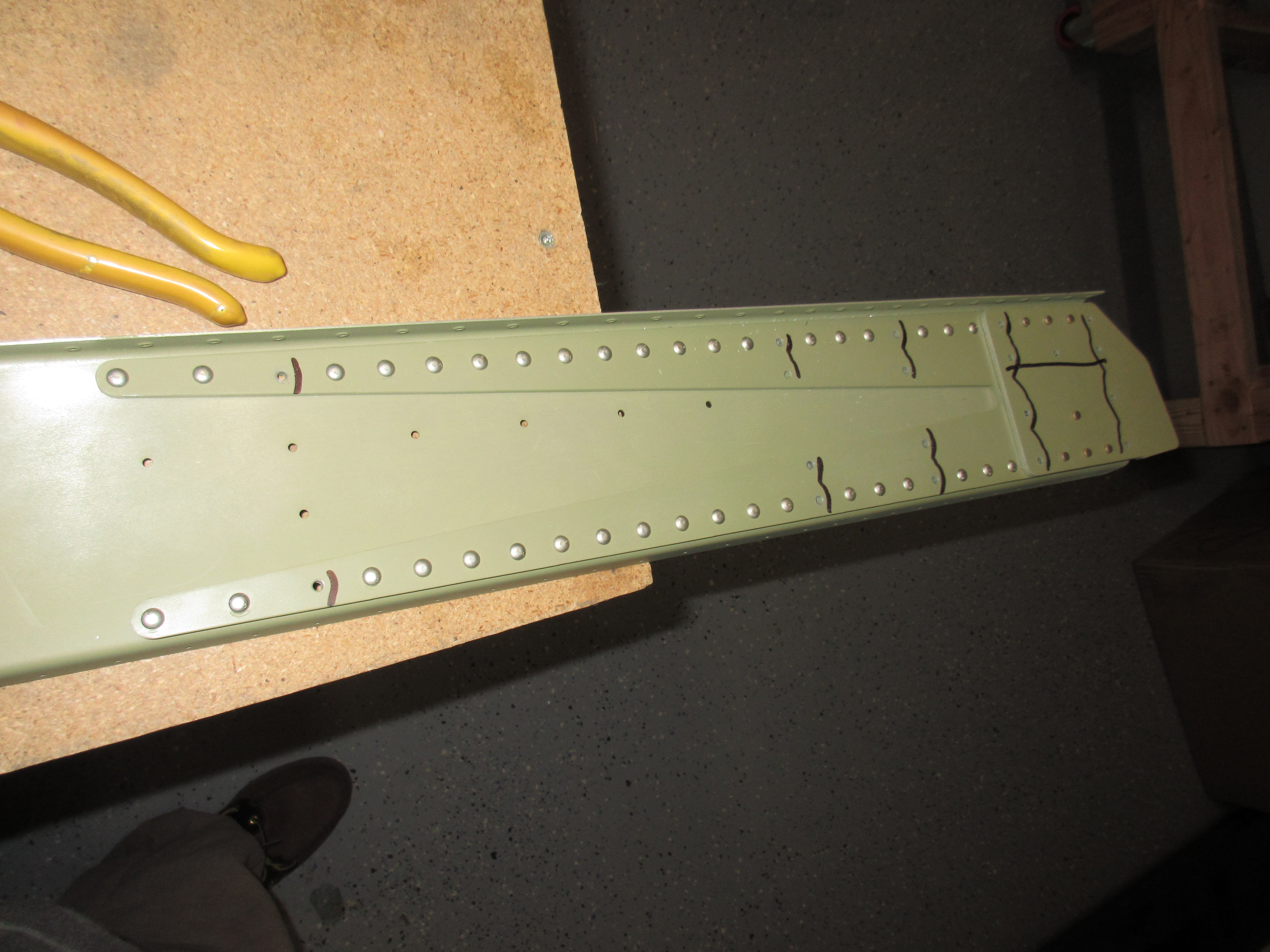
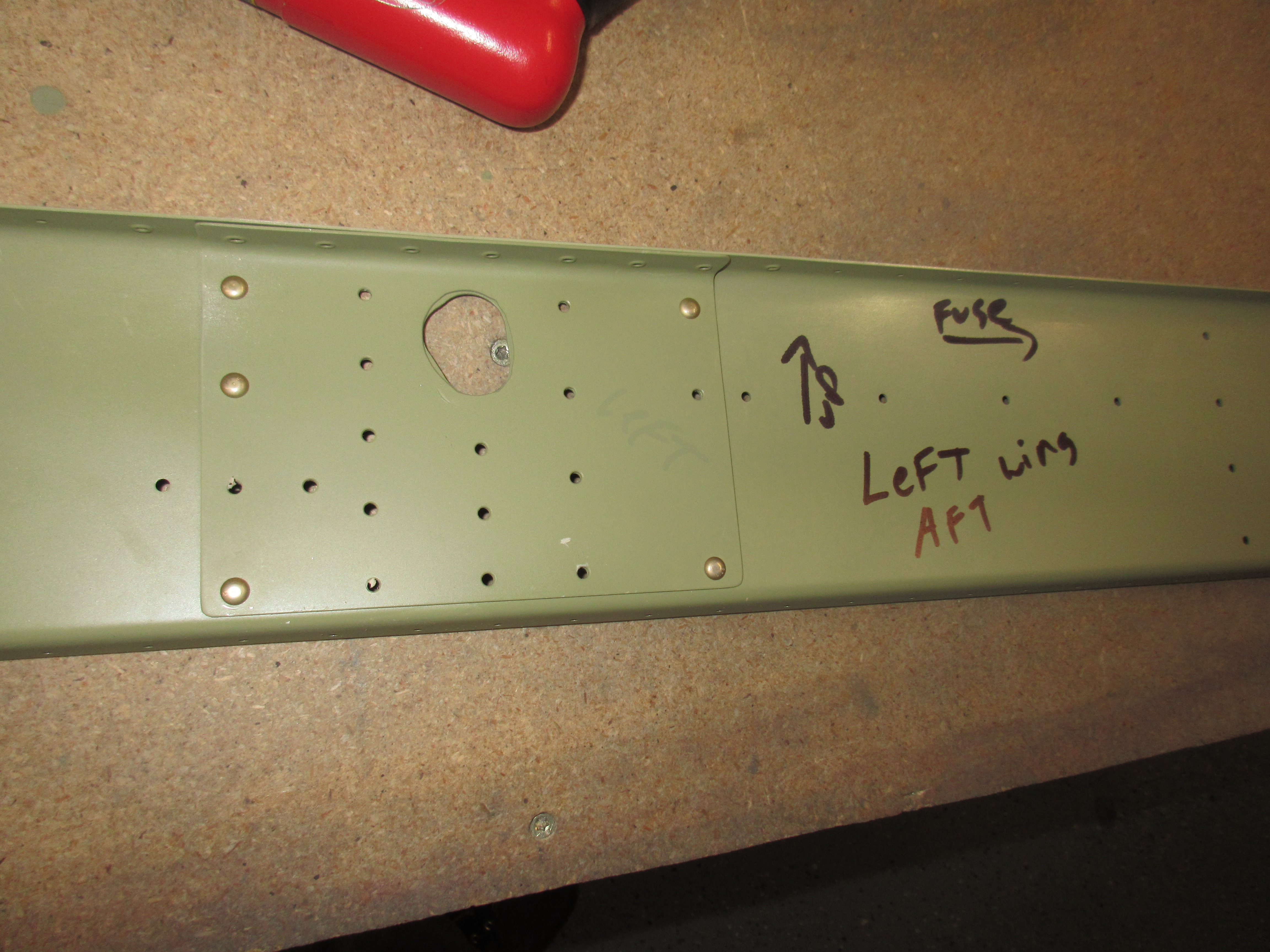
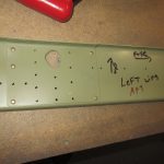
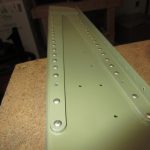
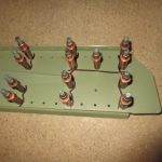
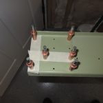
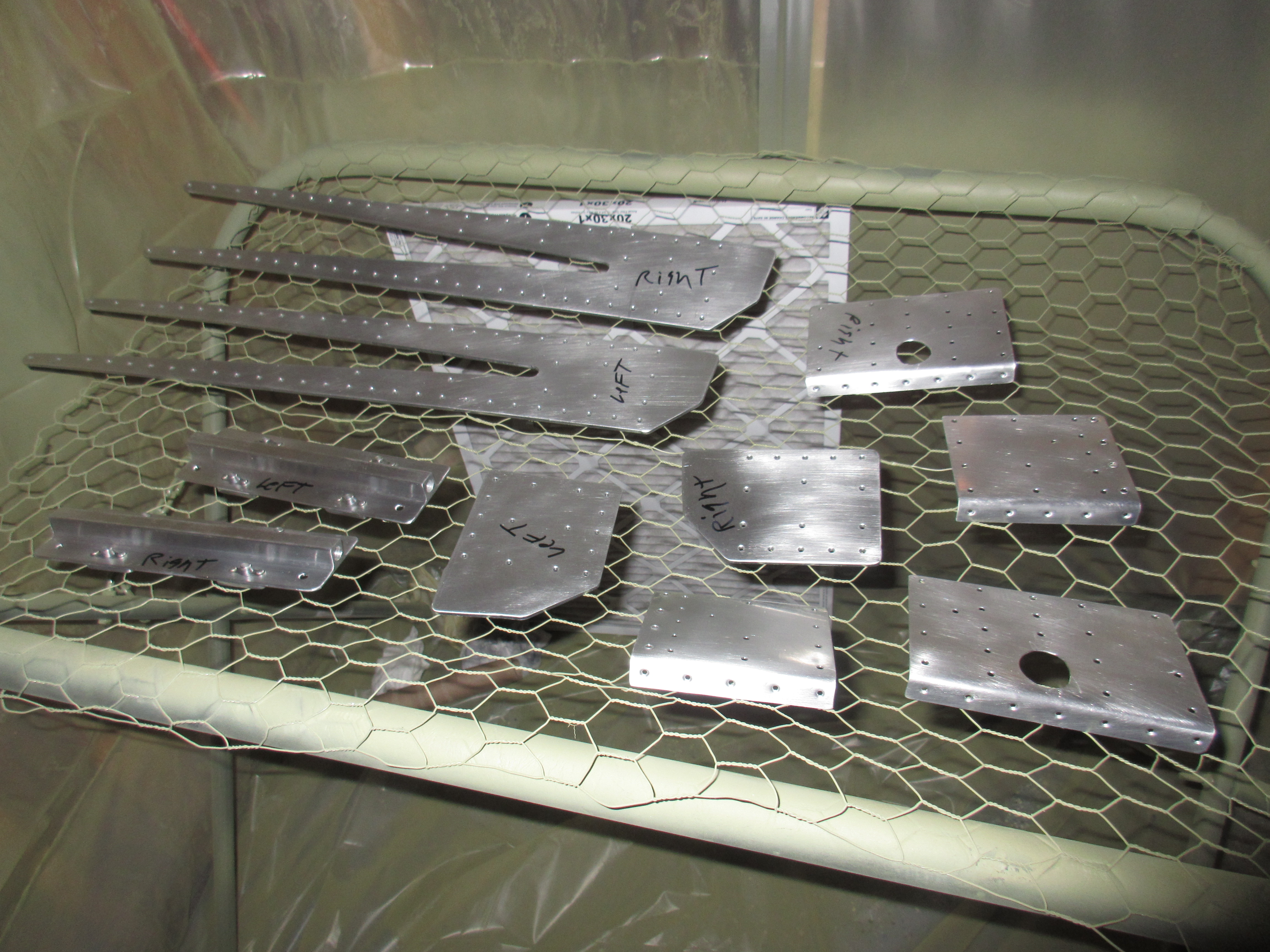
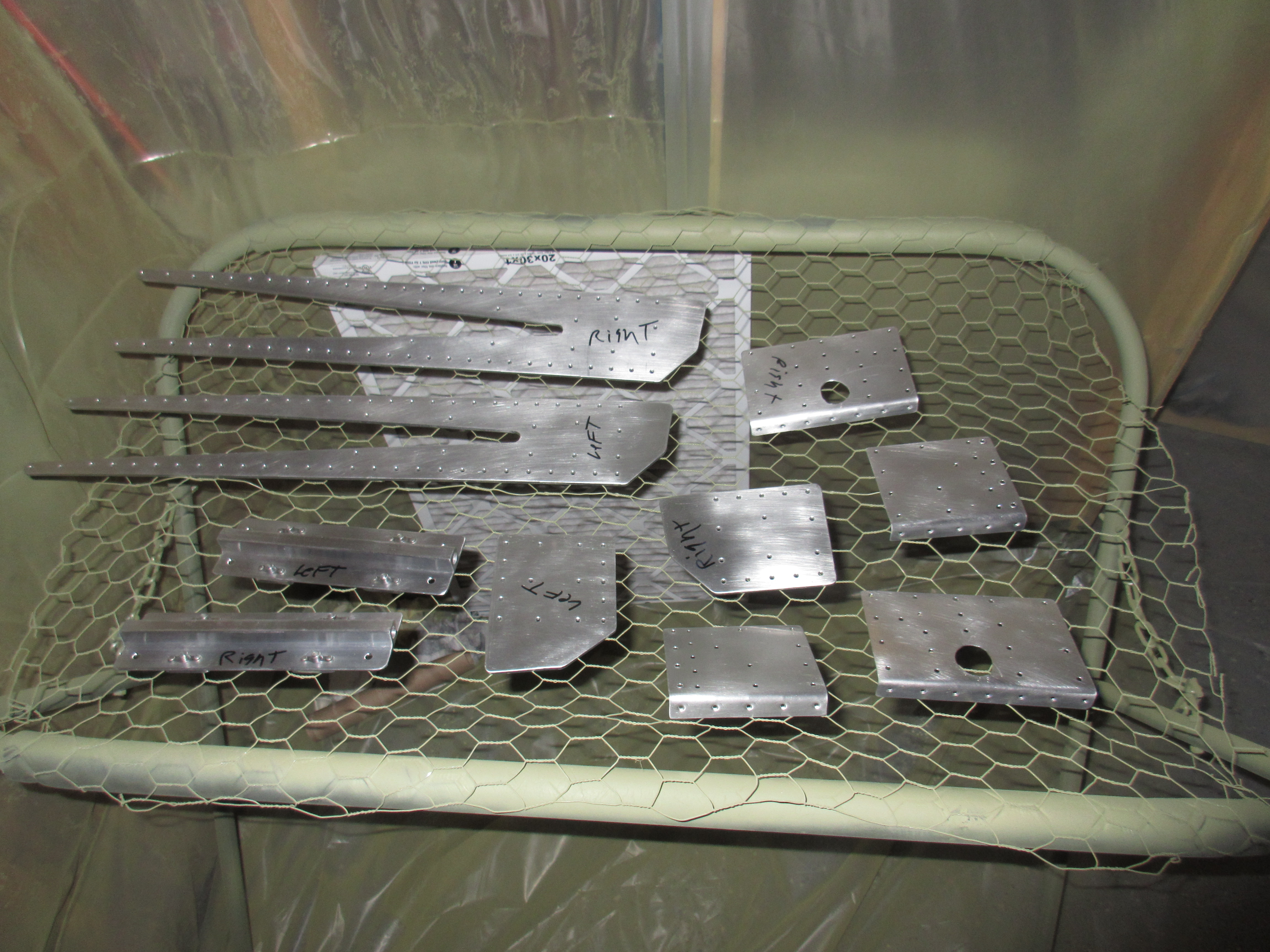
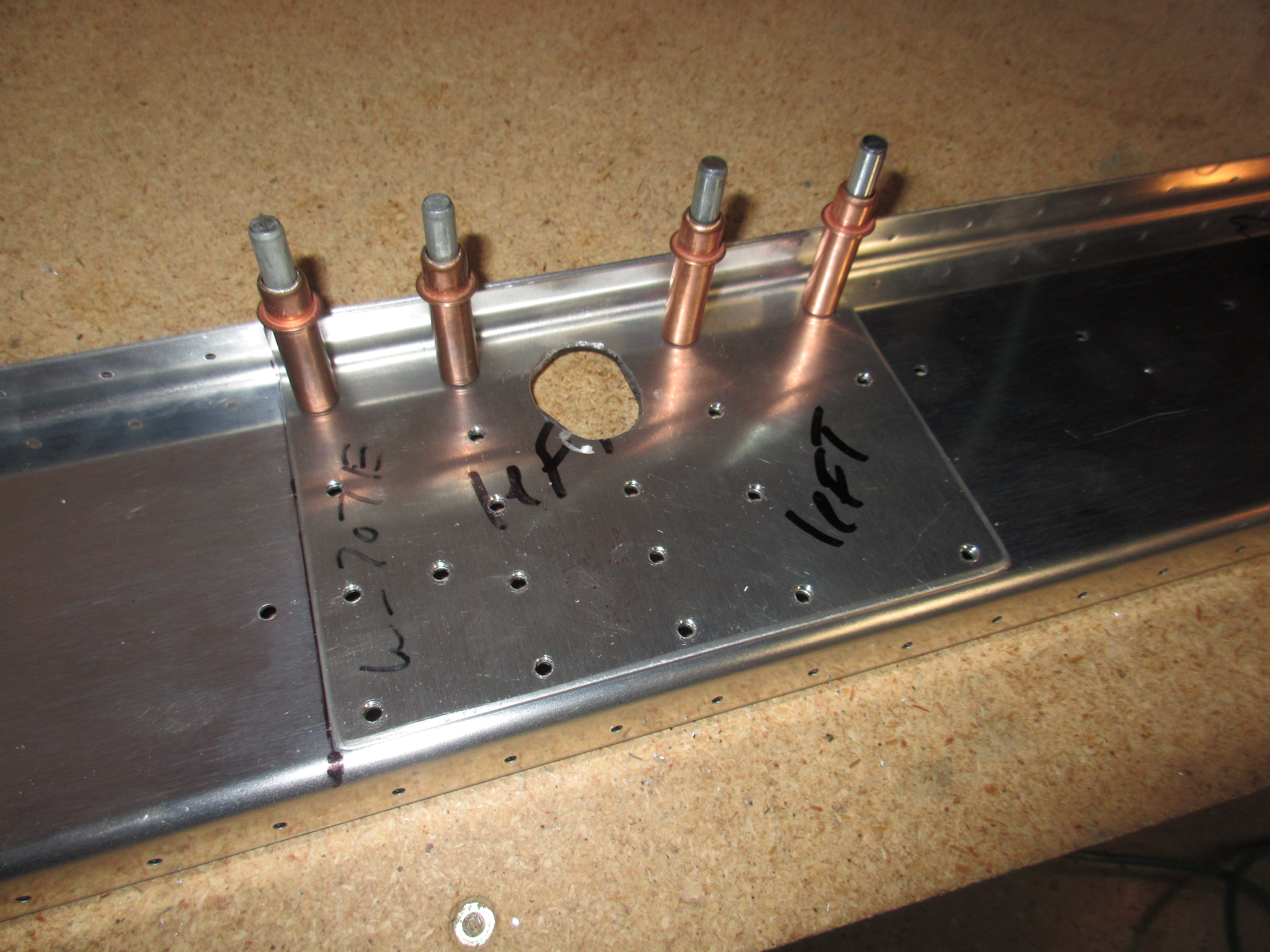
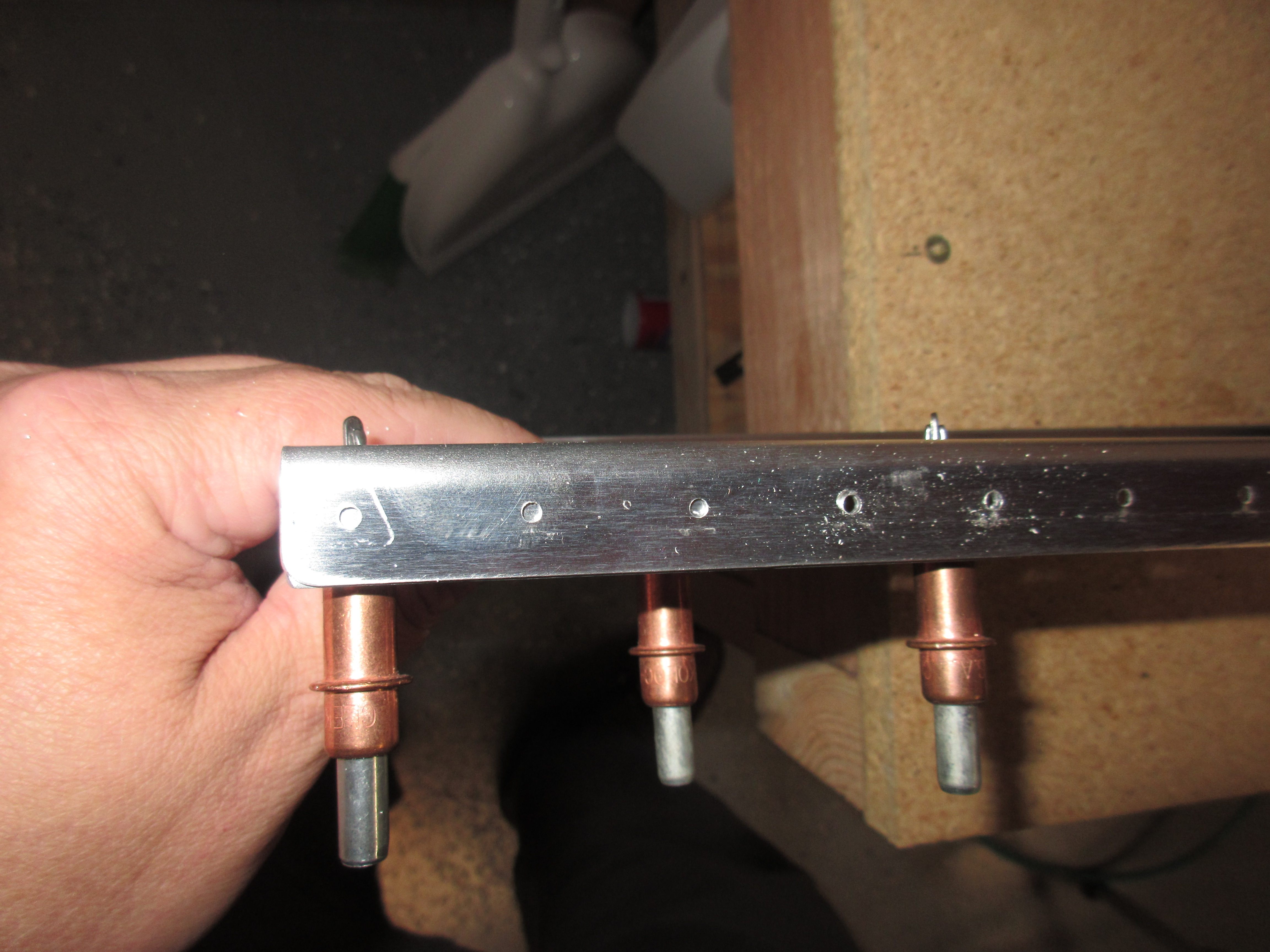
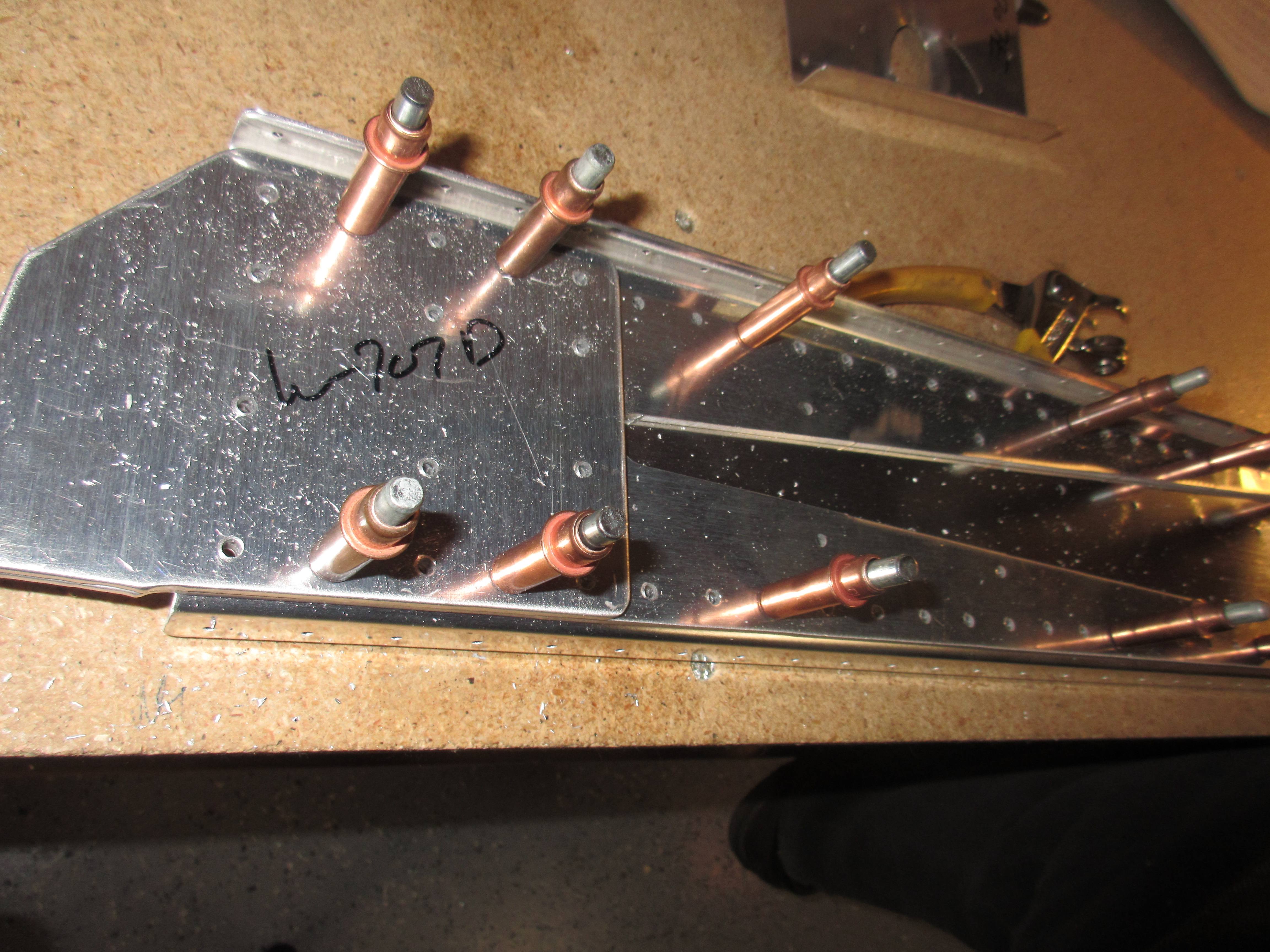
I still had a little steam left, and I wanted to get these rear spar parts completed to all that was left was hole deburring and then priming, so I pushed on to the match drilling of the W-707G reinforcement fork and W-707D doubler plate.  I studied over the plans to make sure that all the holes were using a #30 drill, and then clecoed the reinforcement fork and doubler plate to the rear spar channel.  I did both rear spars at the same time since it was easier this way.  Then, lastly, match drilled all the holes to #30 on both rear spars, and marked the parts which was left and right.

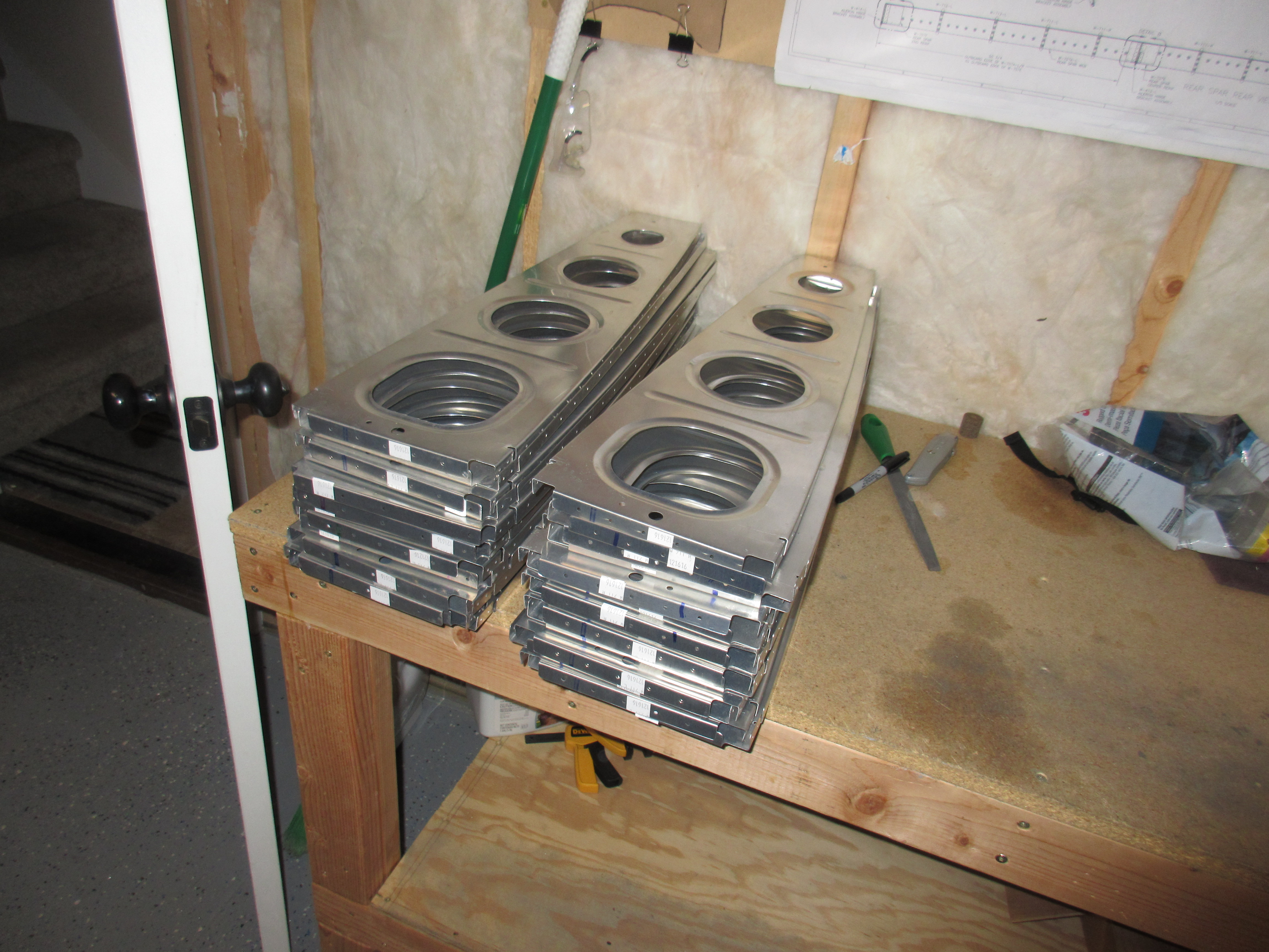
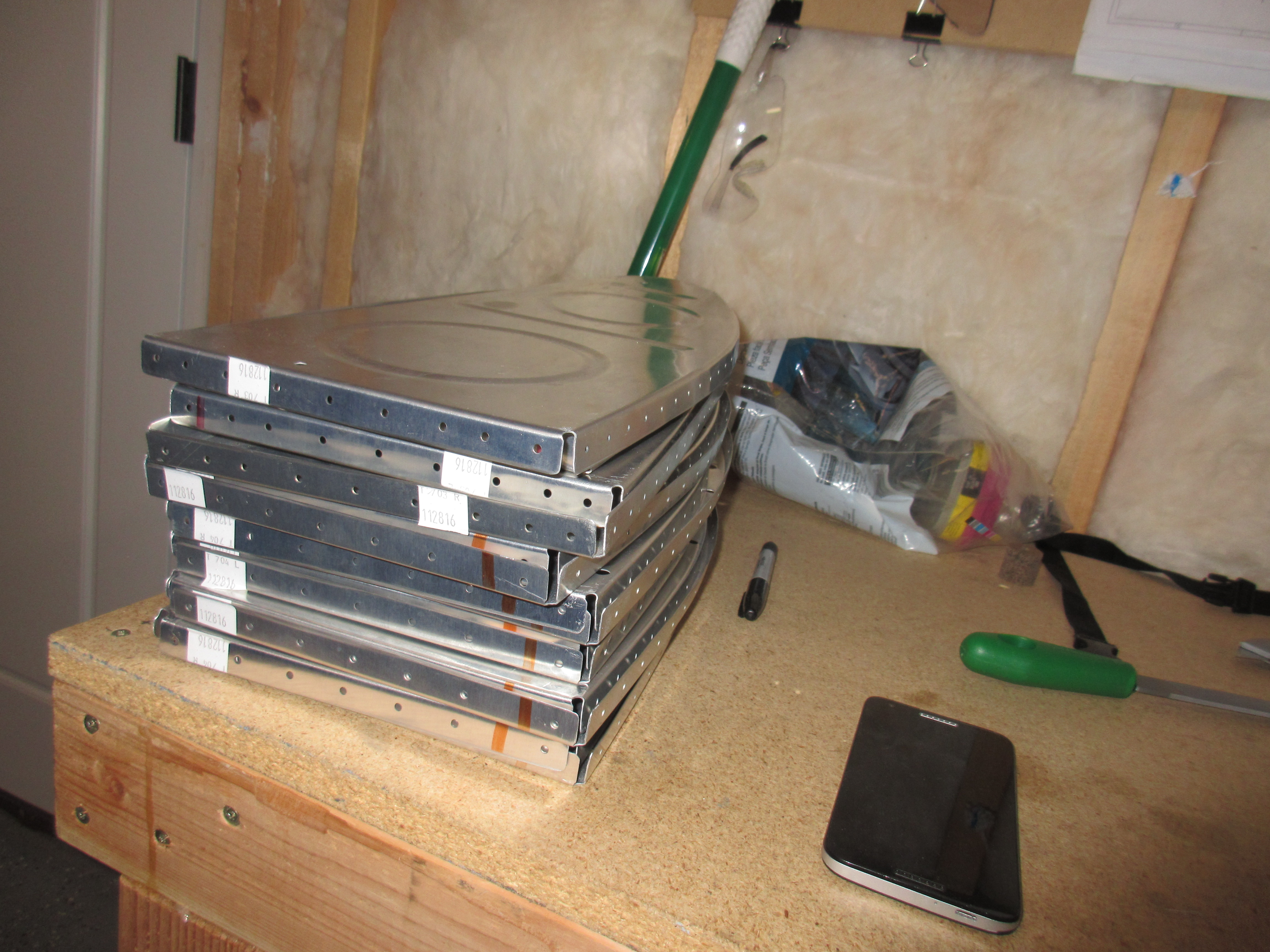
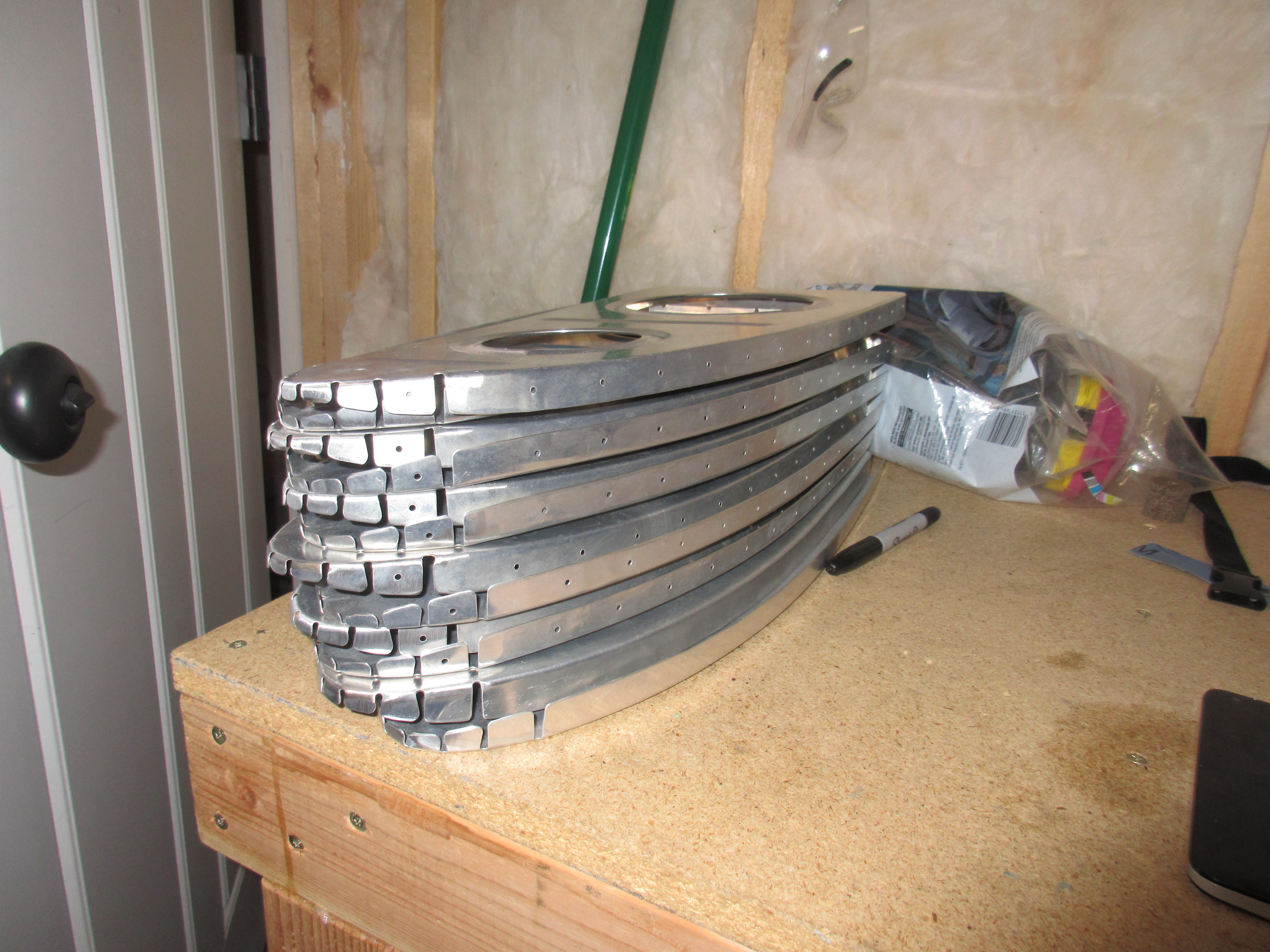
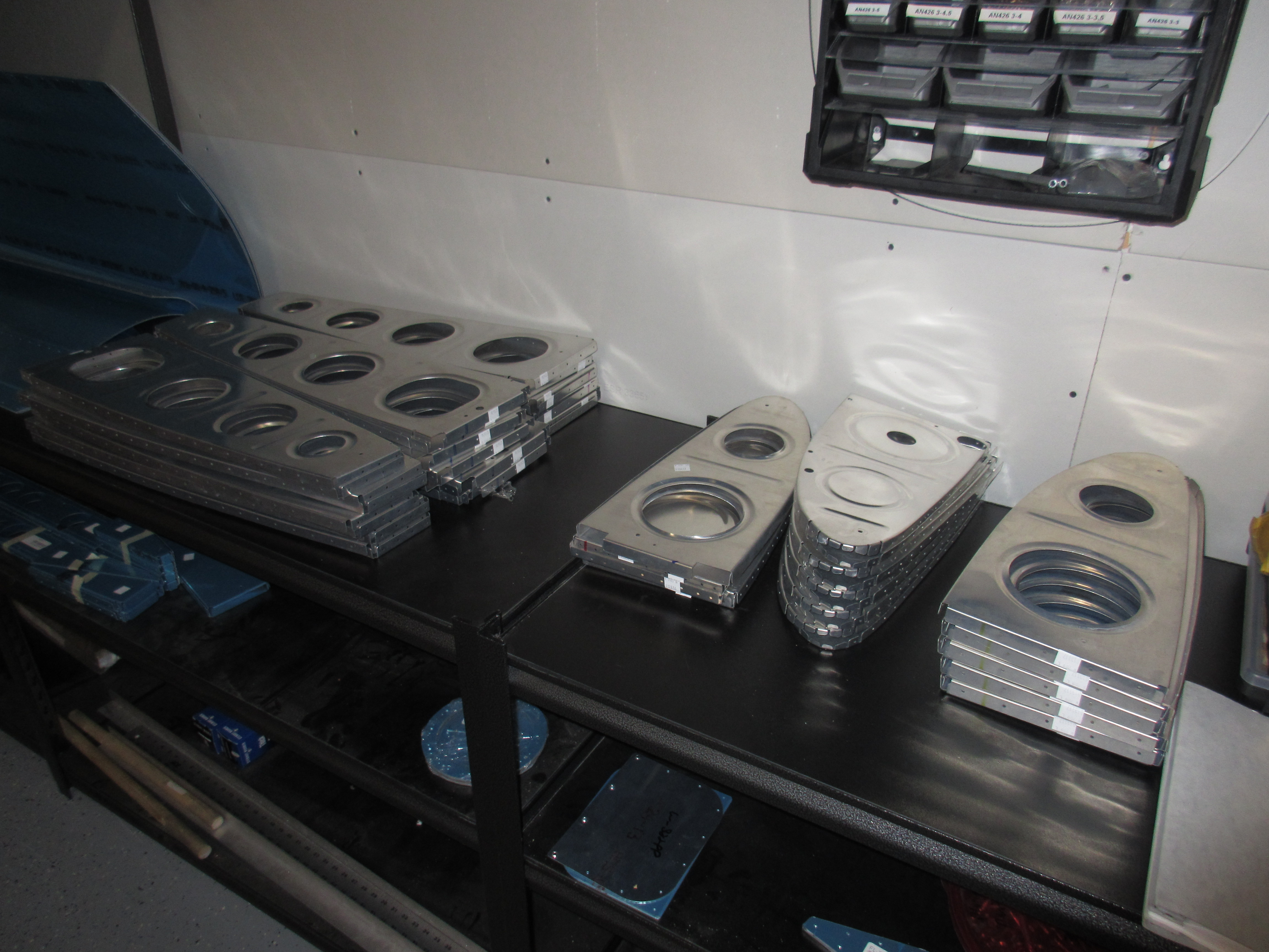
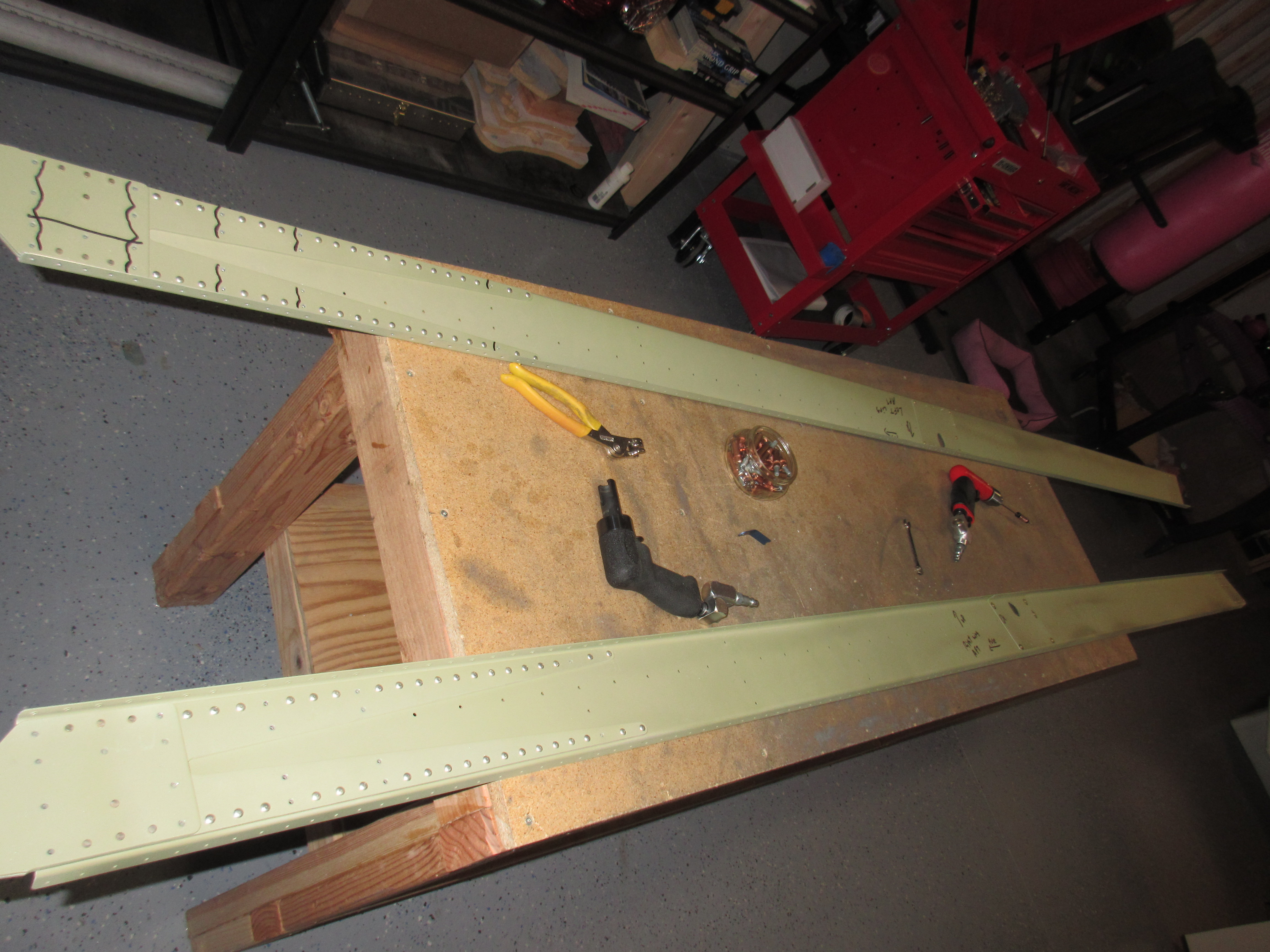
Thats it for tonight.  I’ll save the deburring of the holes for tomorrow, and possibly a priming session on Sunday.  Whenever I prime these rear spar parts, I’ll also prime the tie-down brackets so they can go ahead and get mounted up.  Here is all the photos from tonights work:


Google Photos Link: https://goo.gl/photos/Yjaue9L3JMiy9Jgf9

Hours Worked: 3.5