Riveting the Left Elevator Skin

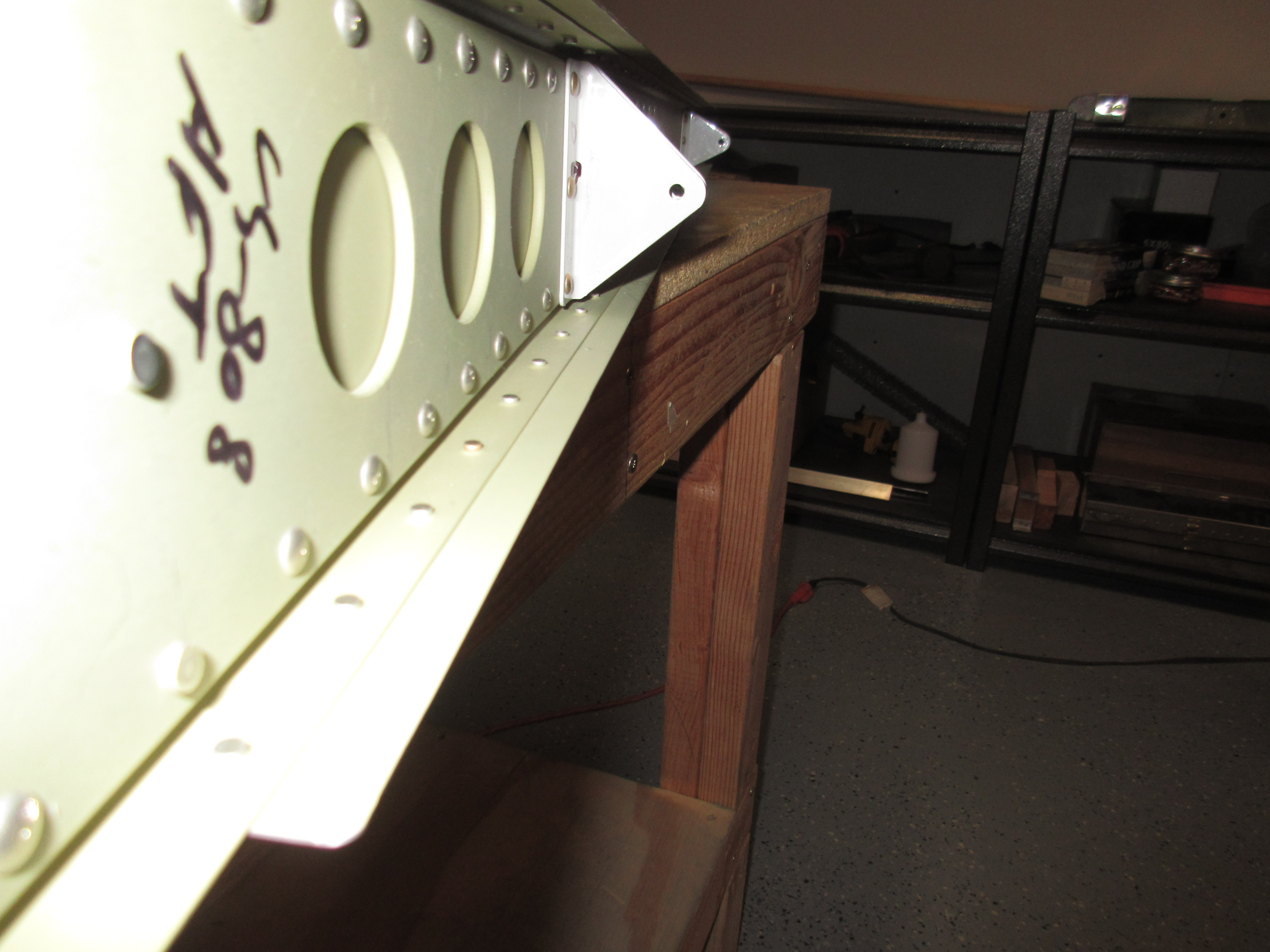
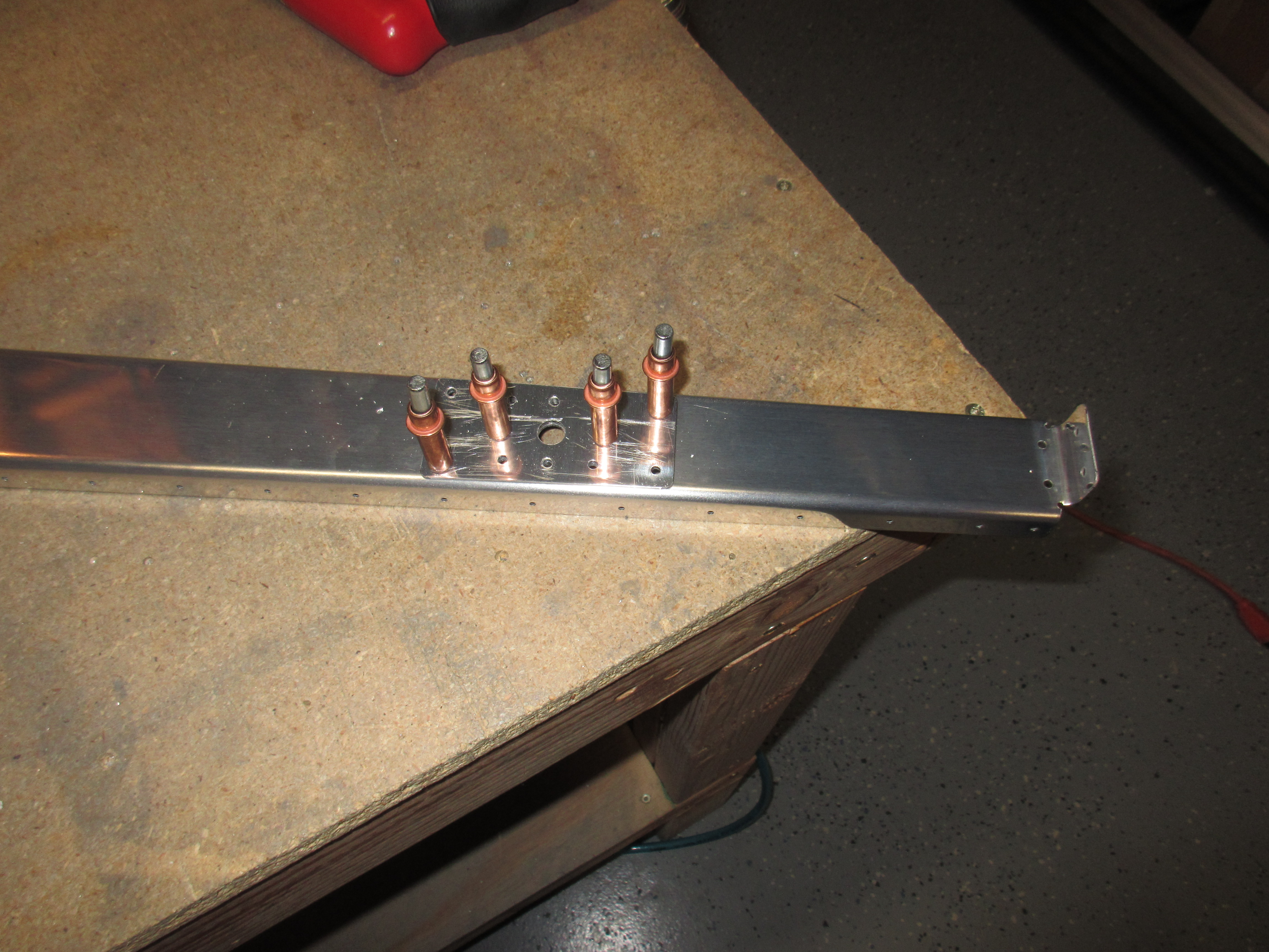
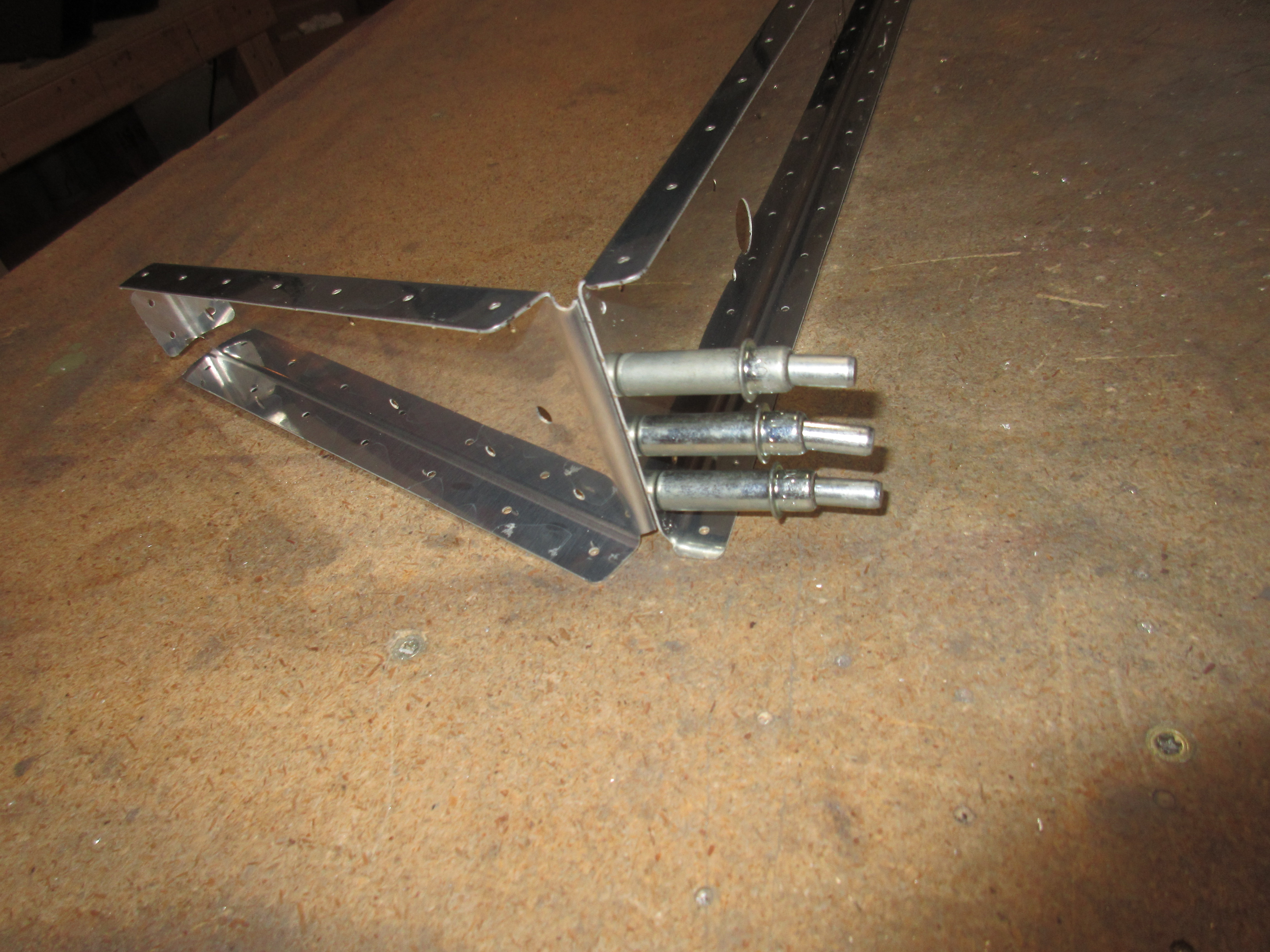
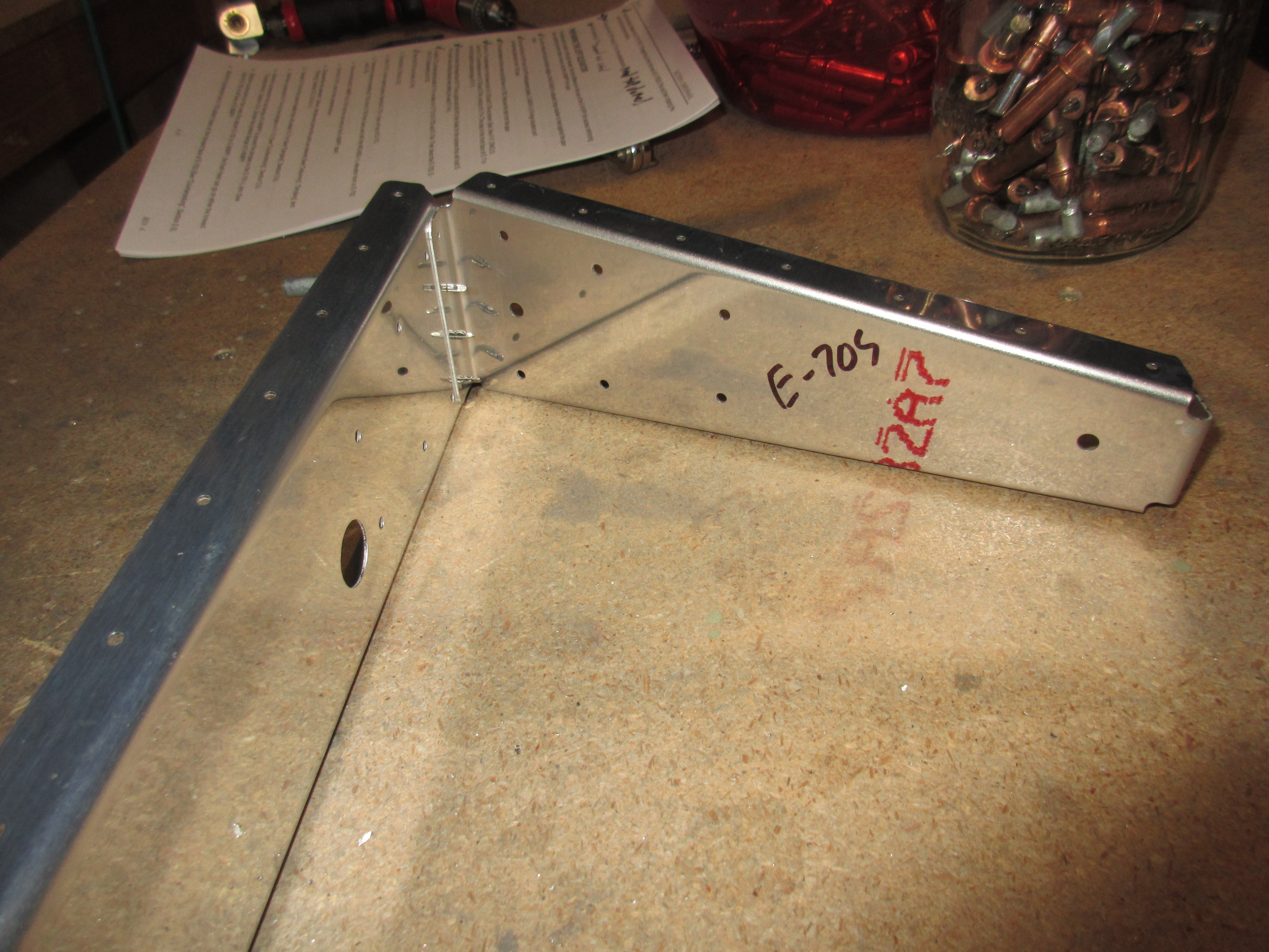
Tonight I worked to rivet on the skin of the Left Elevator and the last few remaining parts of the skeleton for it as well.  In the last work session, I completed the spar and a few other parts, but tuckered out before I got to the skin.  I started out by riveting the E-703 tip rib assembly to the E-702 spar, making sure to get the hard to reach rivets first.  The last time I did this on the right elevator, I left two rivets that were hard to reach with a squeezer in a bad position, and I spent a couple hours working on it to get them riveted.  I learned to get those two first this time 🙂

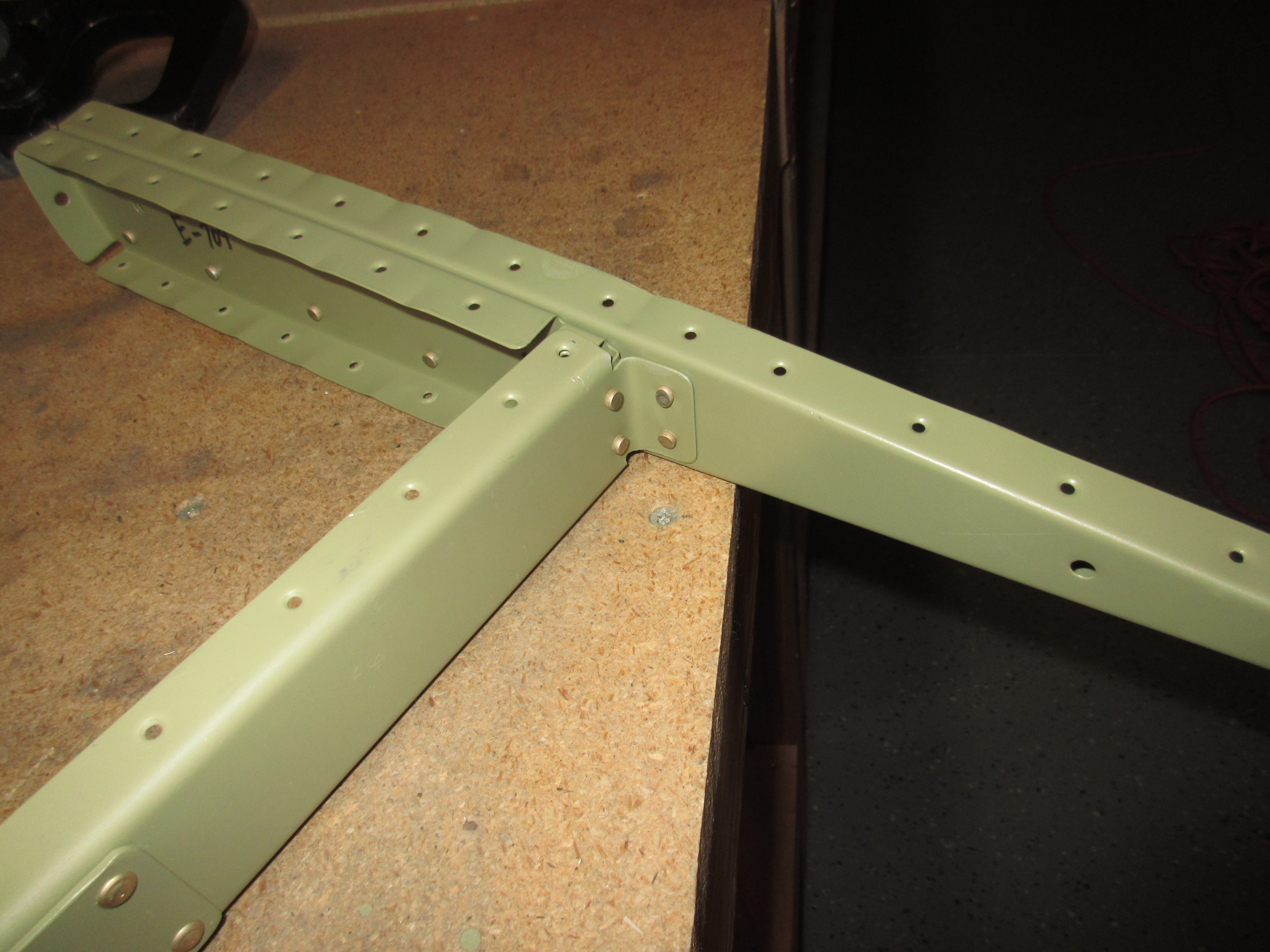
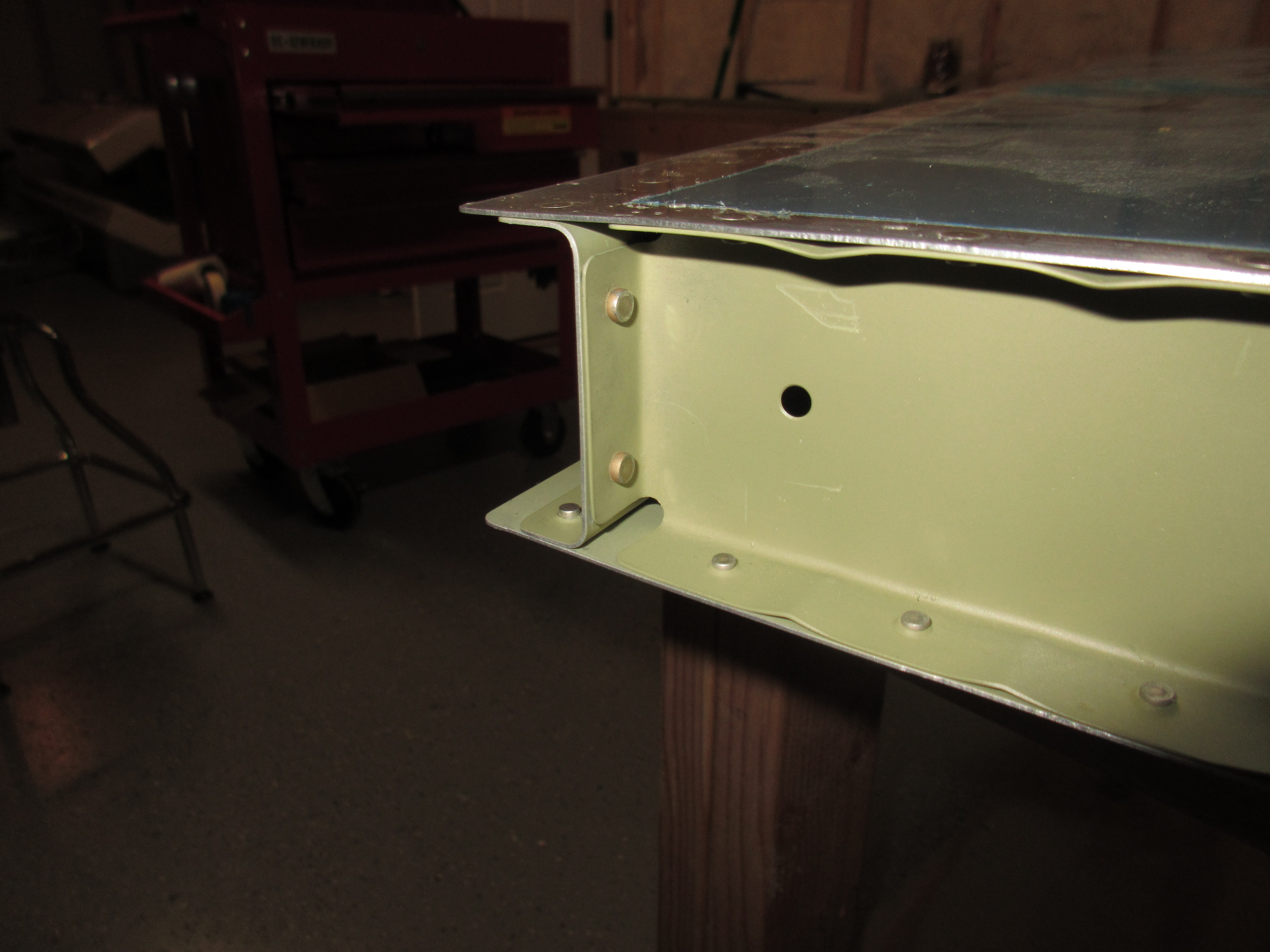
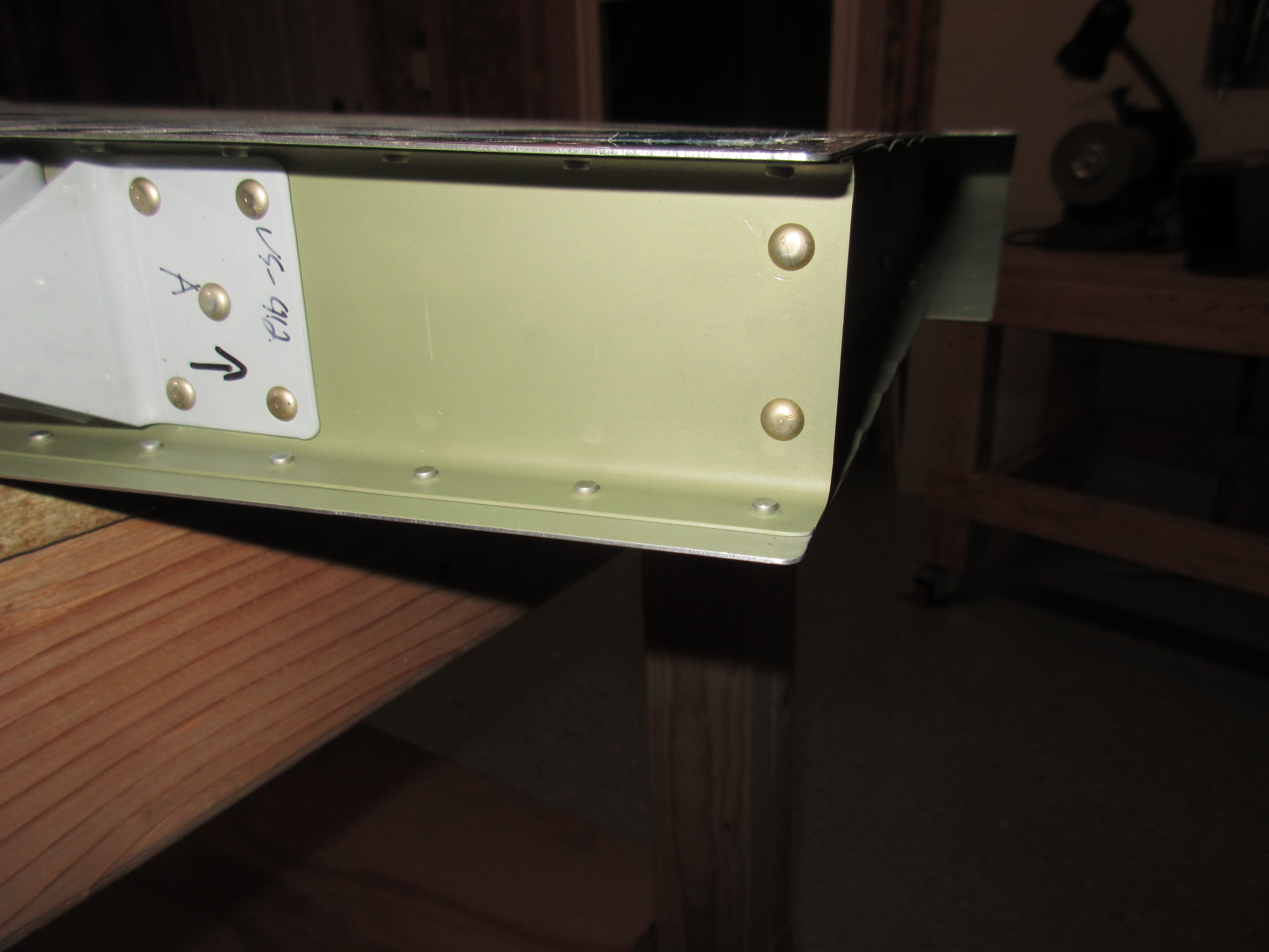
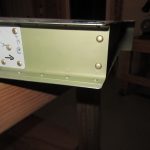
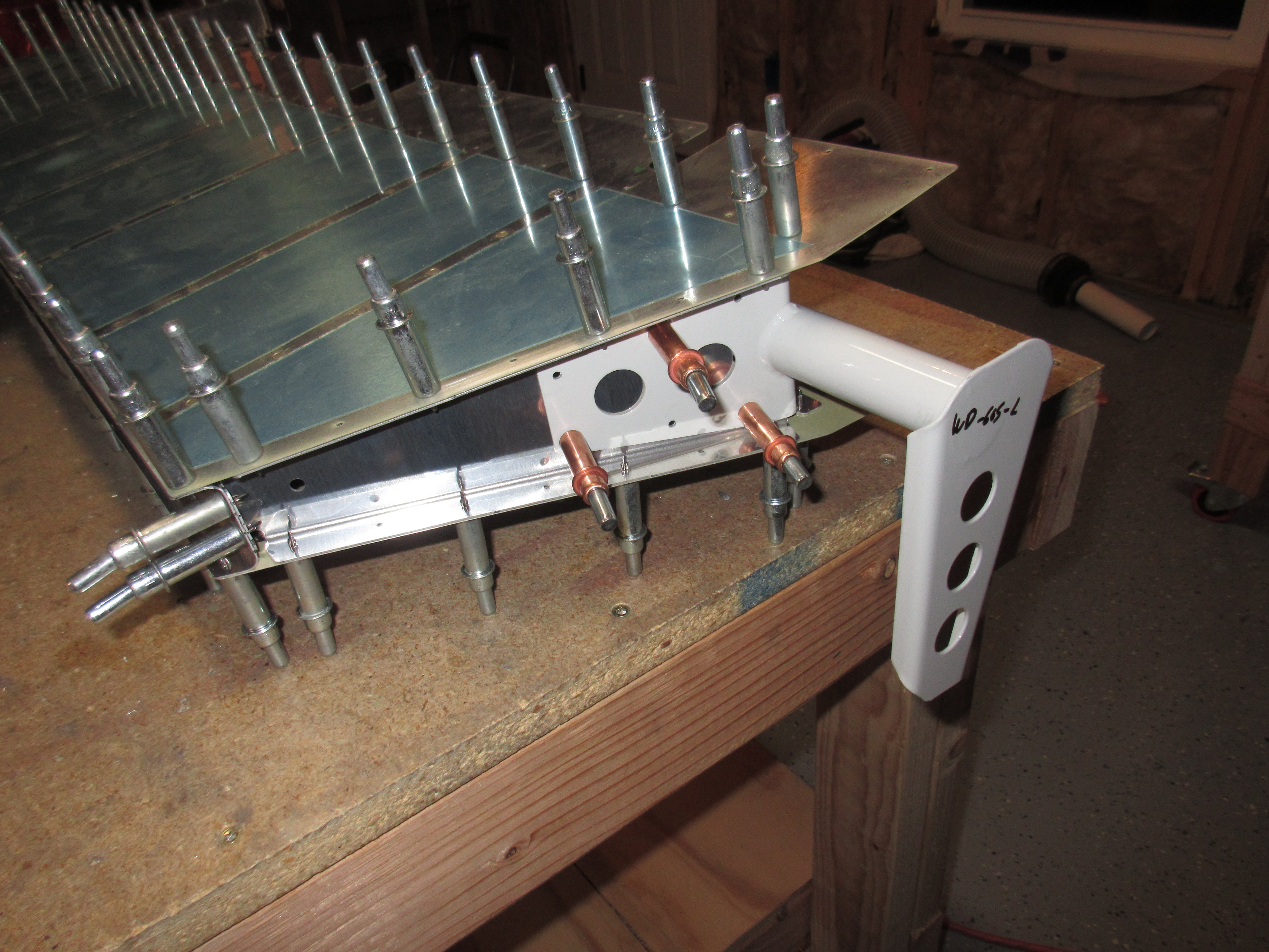
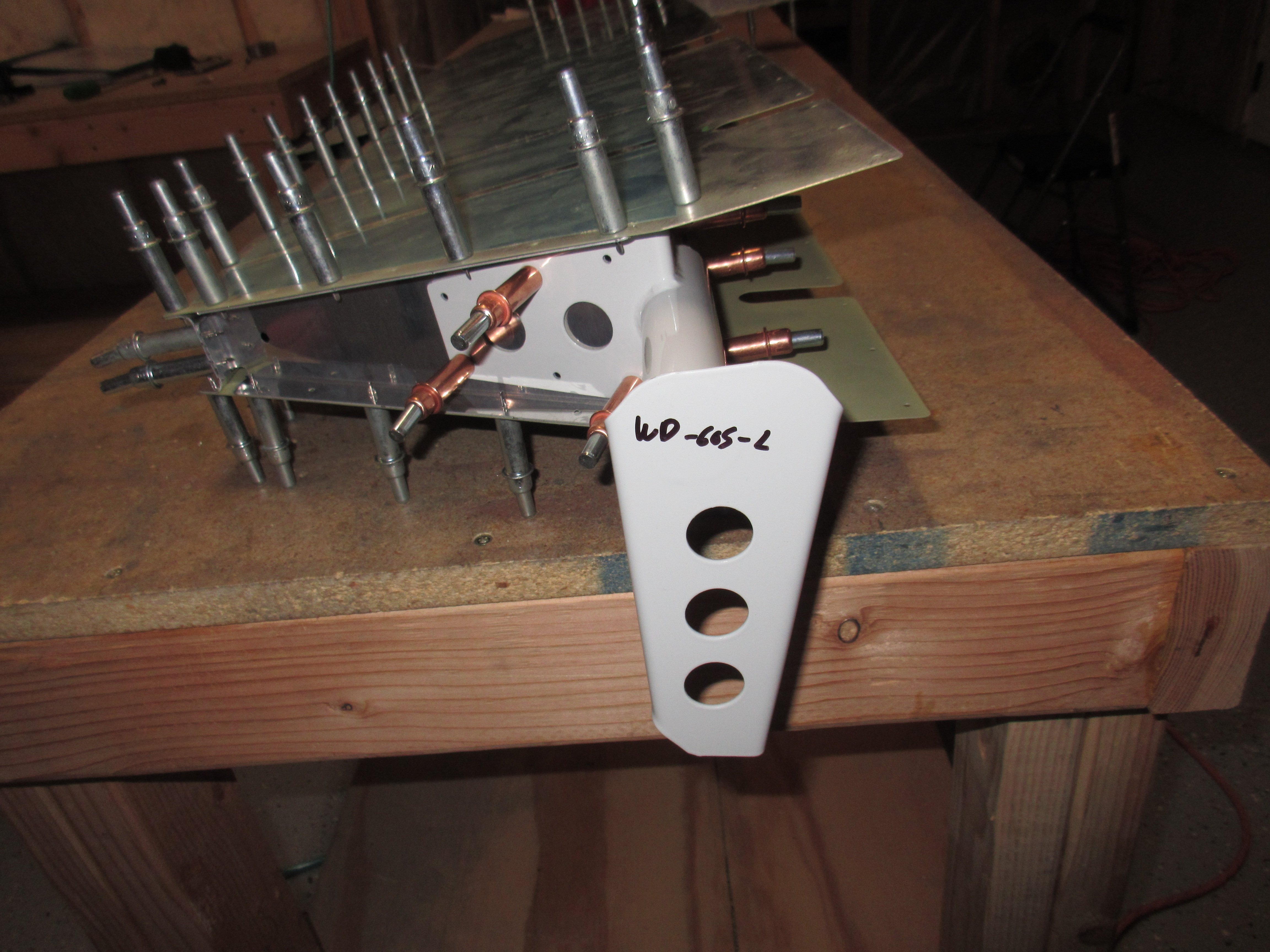
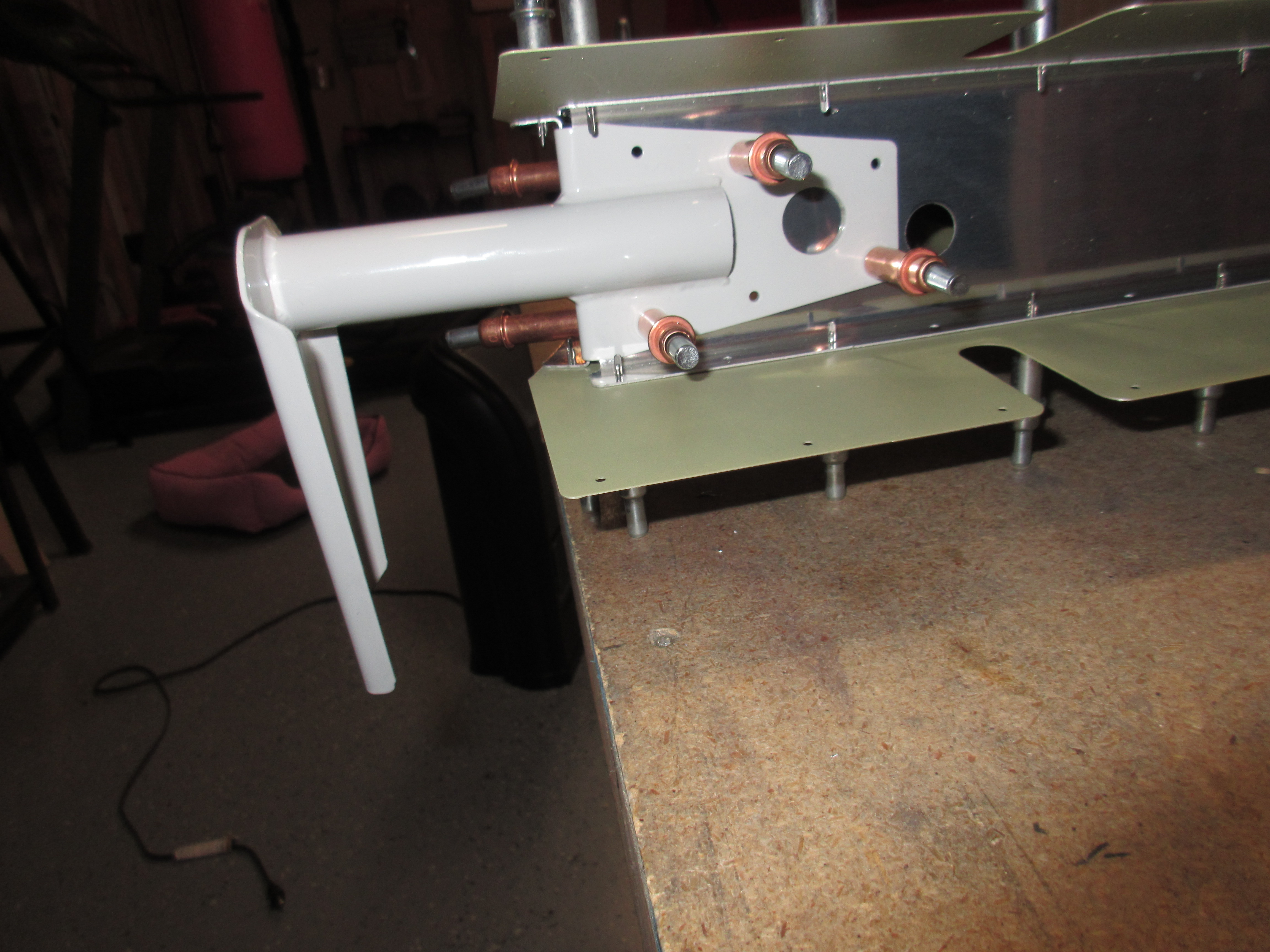
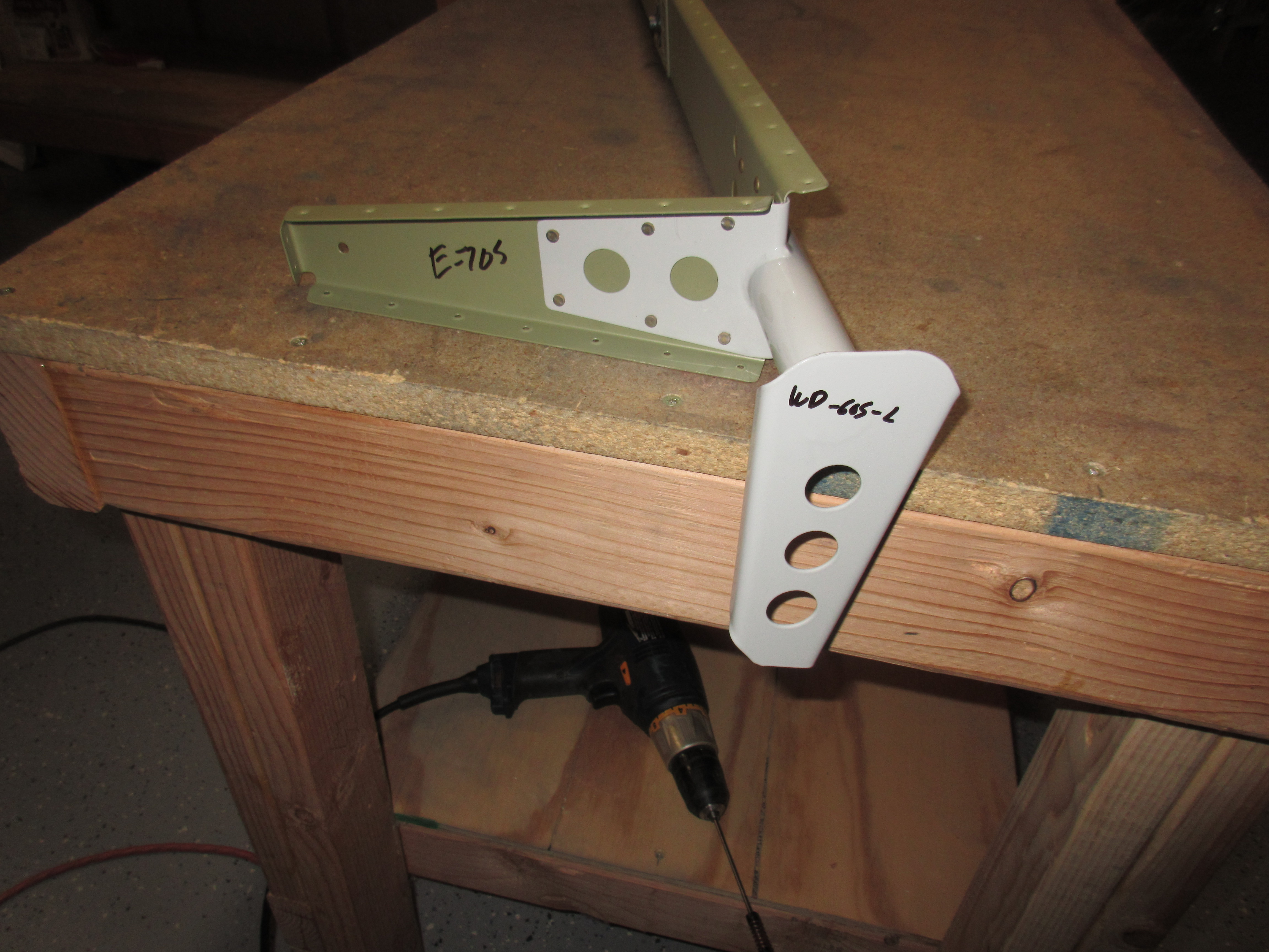
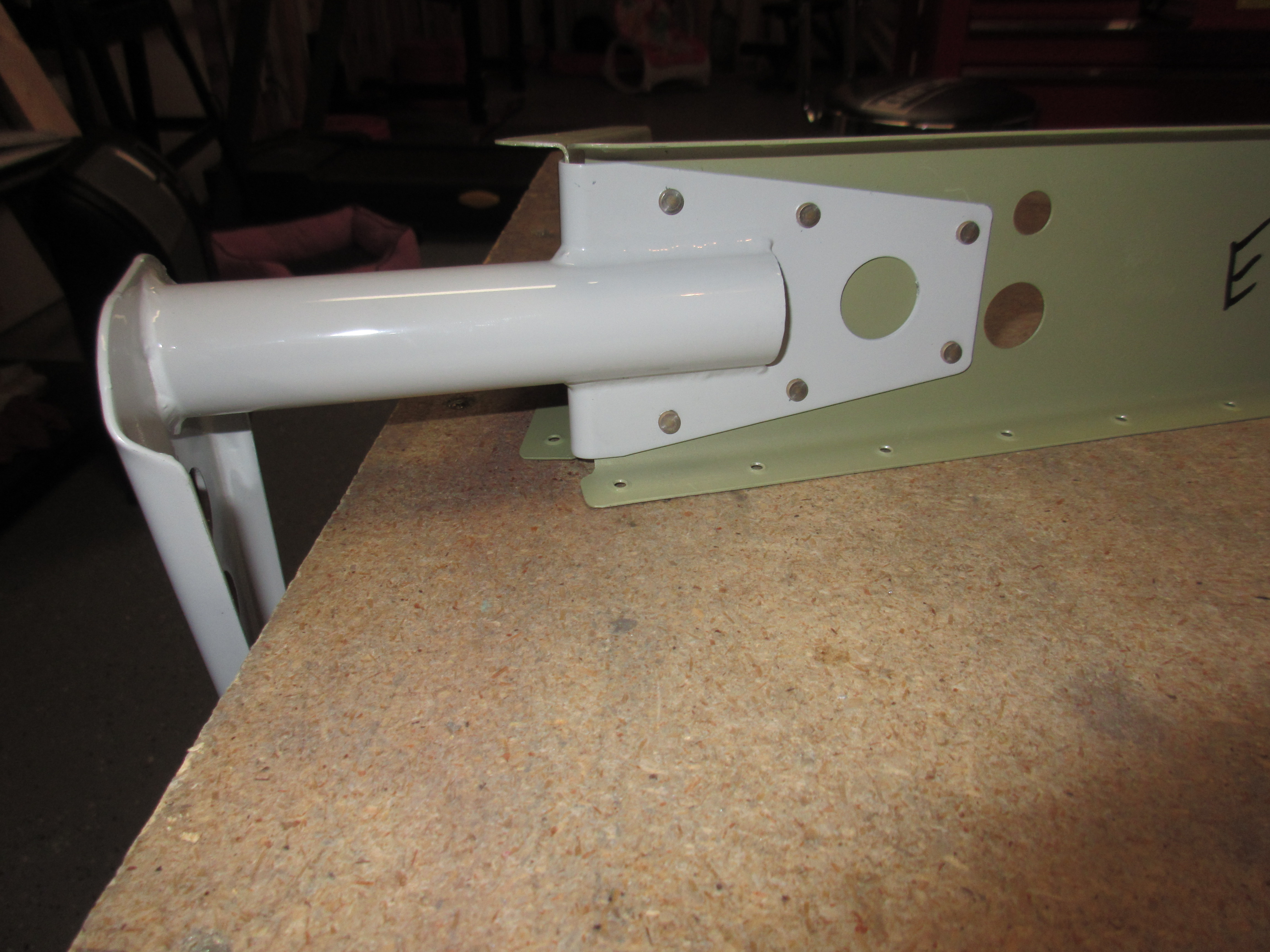
Once I had the tip rib squared away, I moved to the other end and riveted on the E-705 end rib to the E-702 spar, making sure to face the flush rivets in the proper direction so as to not interfere with the WD-605-1-L elevator horn that I riveted next.  These all were pretty straight forward, and I used my squeezer to get a perfectly set rivet on them.

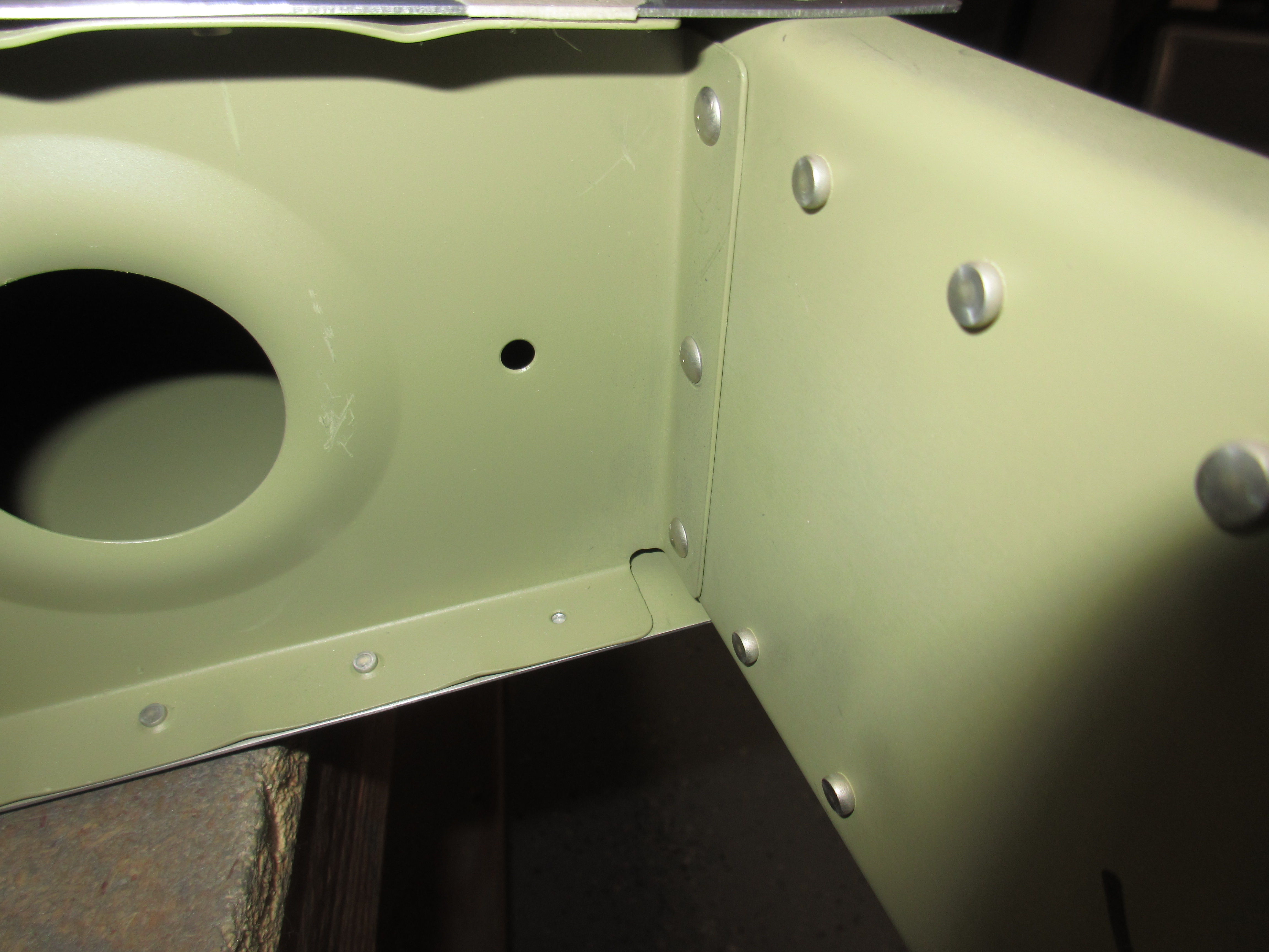
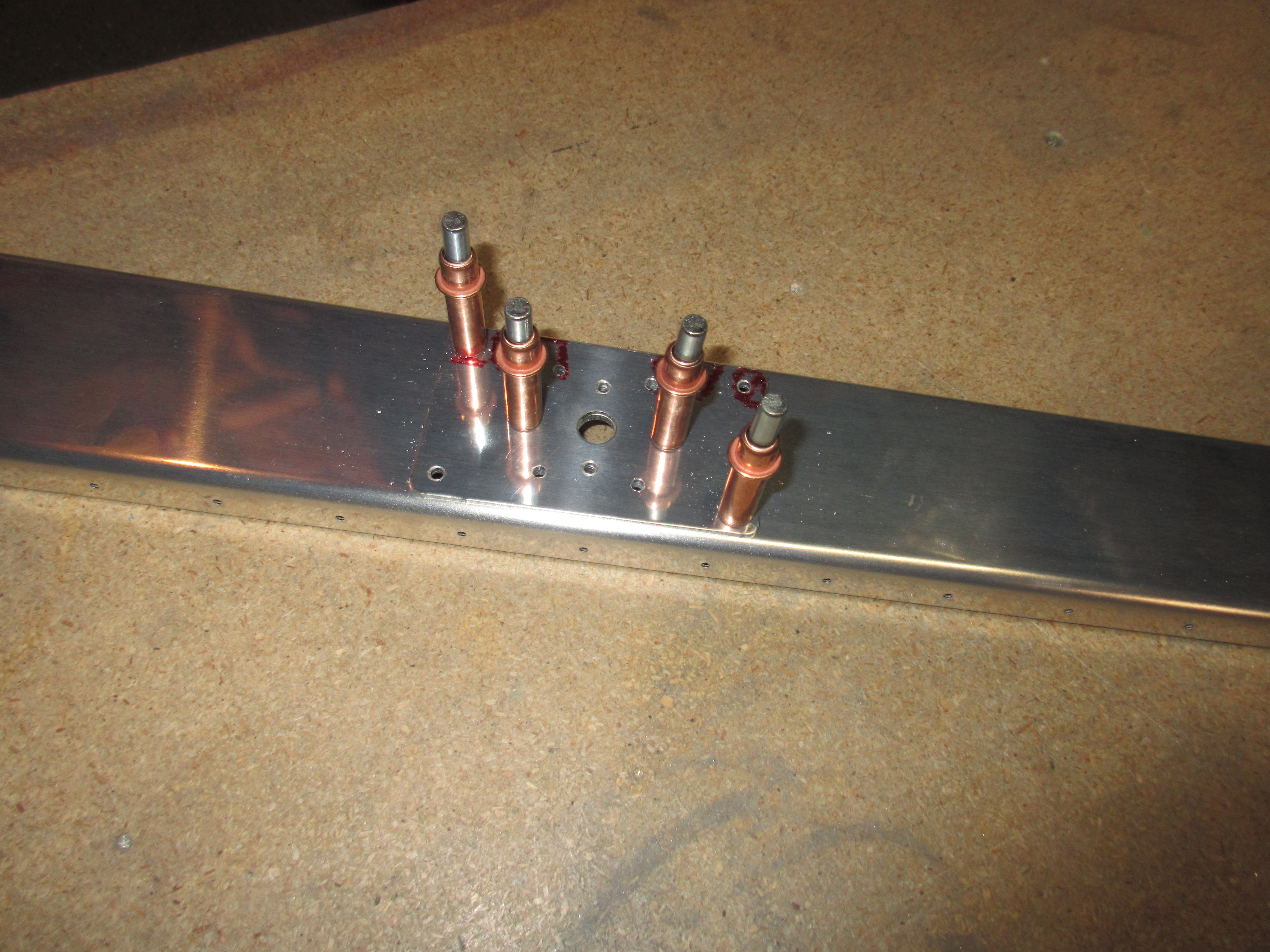
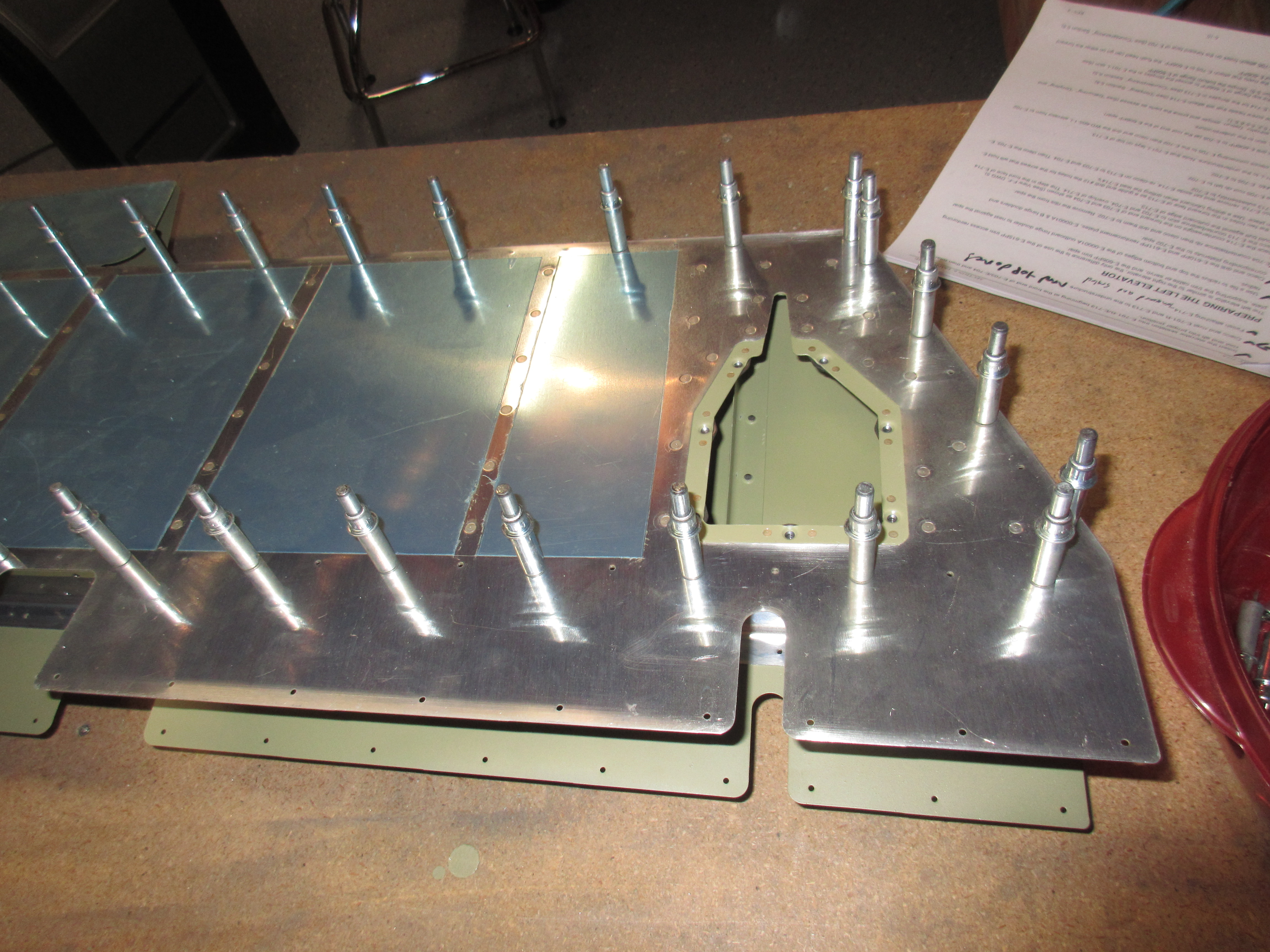
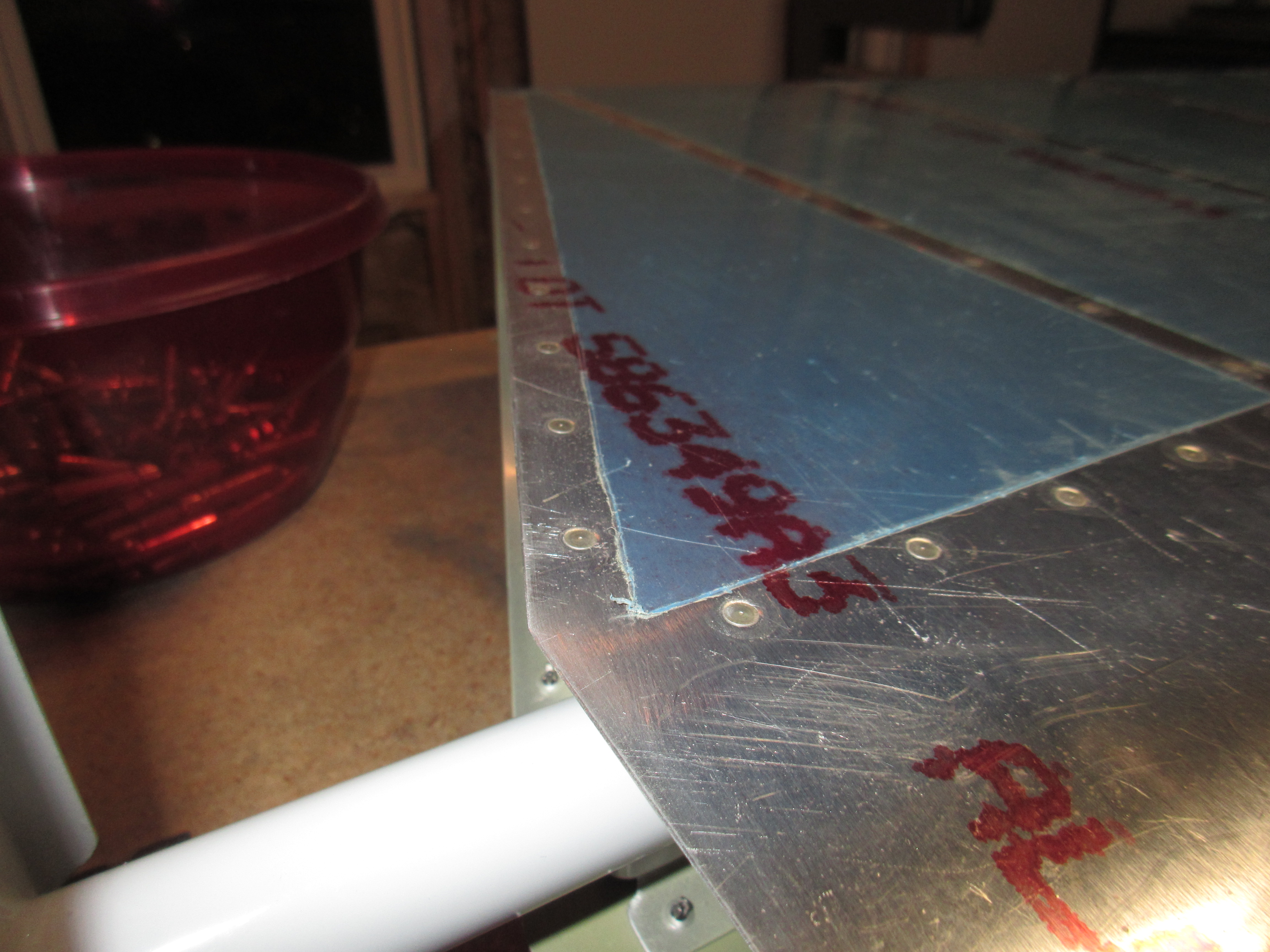
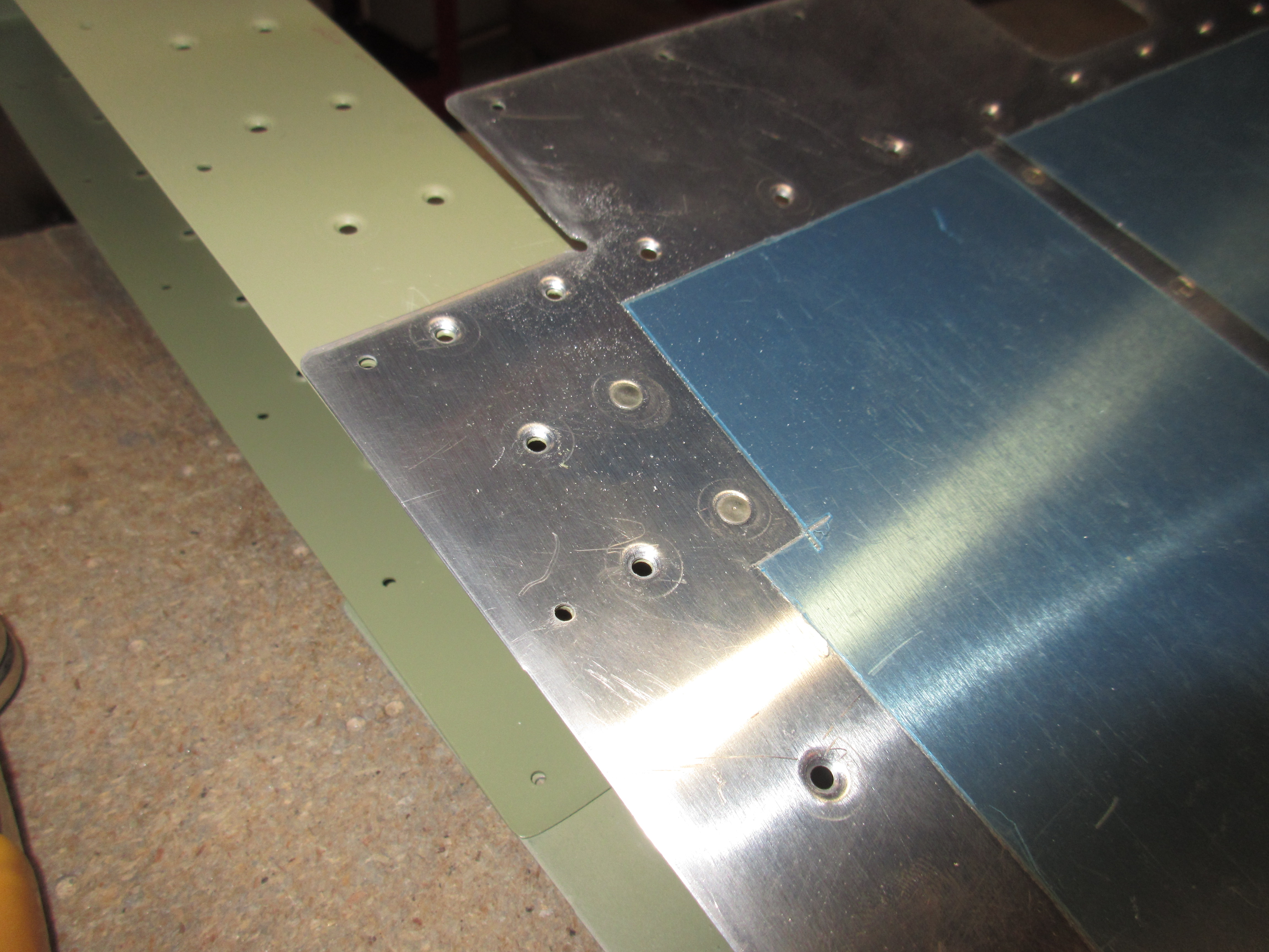
Now its time to move on to the skins.  First, I attached the E-713 counterbalance skin to the E-701 elevator skin with clecos, and noted which two rivet holes I need to set first, before inserting the skeleton.  I opted to set these rivets now, and use AN426 flush rivets instead of using pop rivets after the skeleton is inserted into the skin.  We just have to be cautious to make sure we use the correct holes 🙂

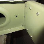
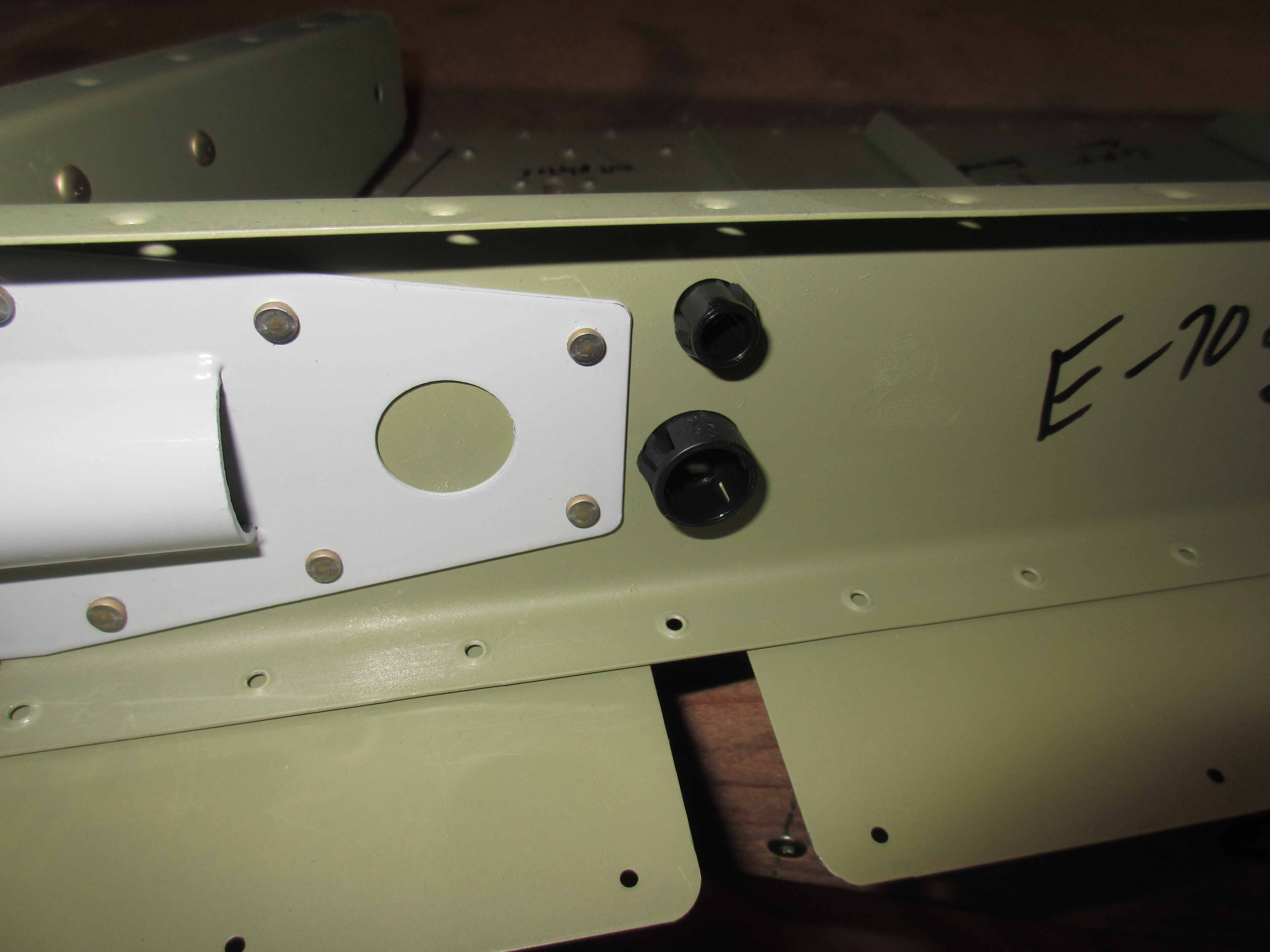
Before inserting the skeleton, I popped in some plastic snap bushings into the holes in the spar for the trim servo jack shaft and wiring.  Its easier to do now than when the skin is closed up.

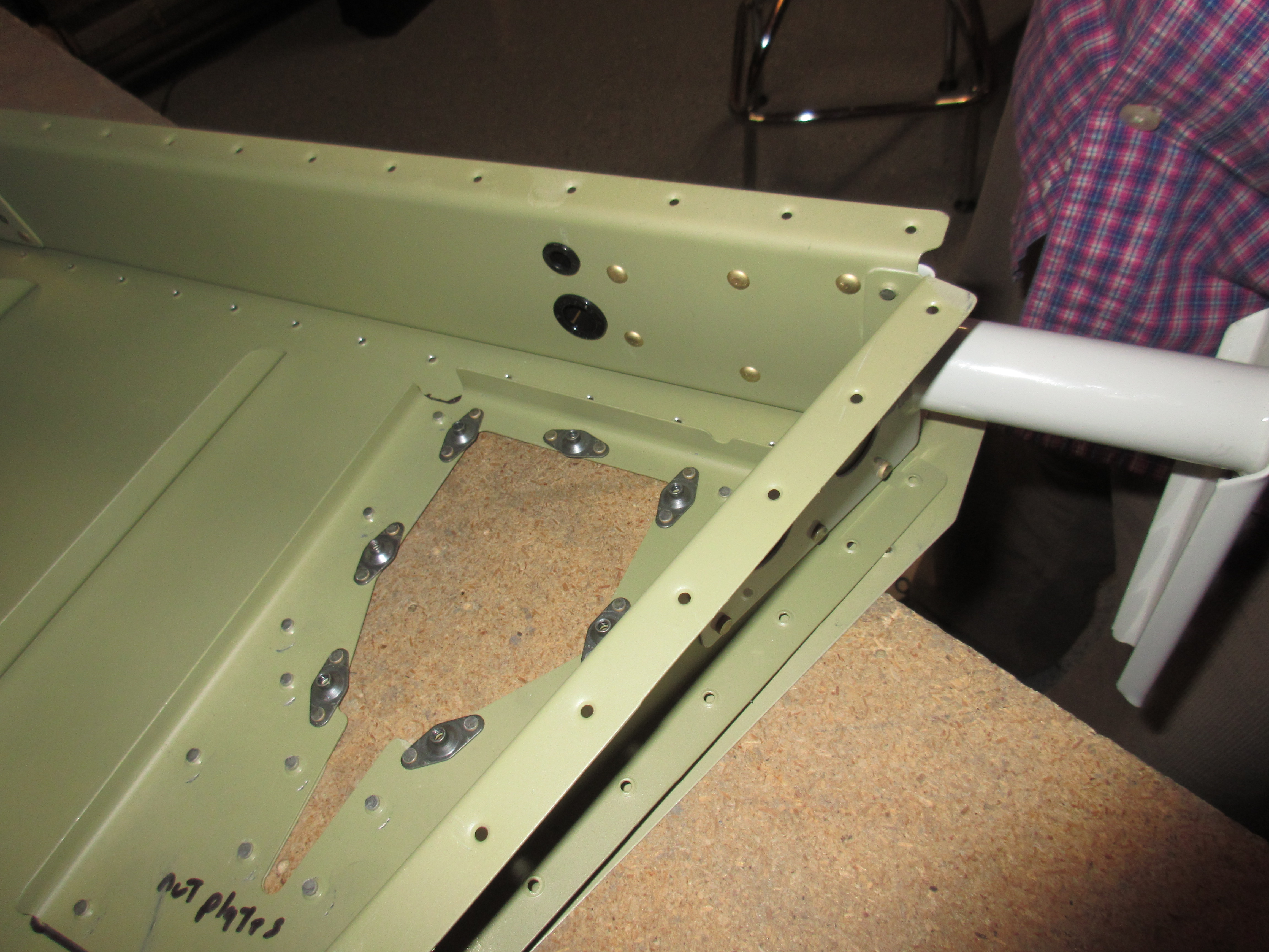
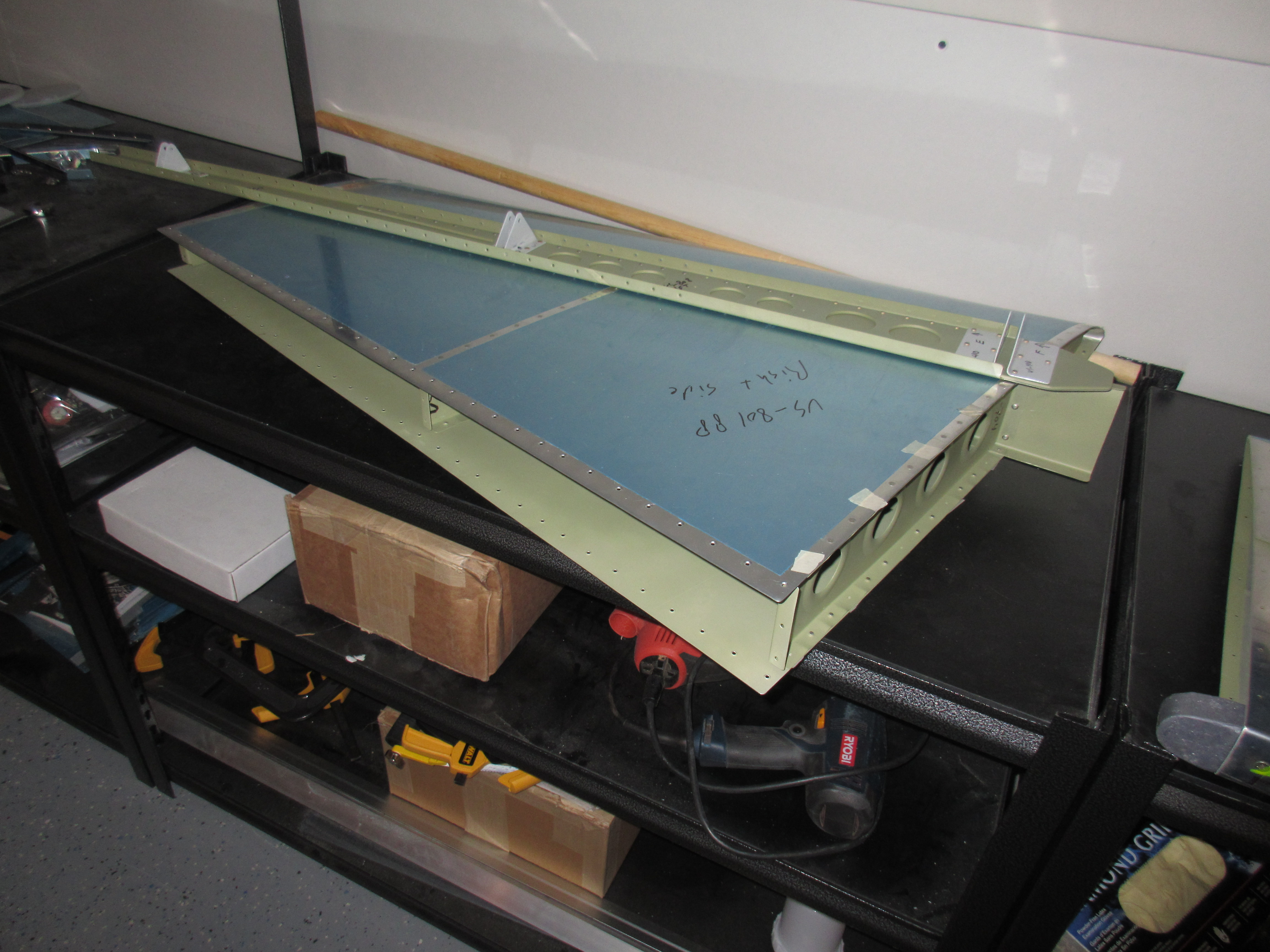
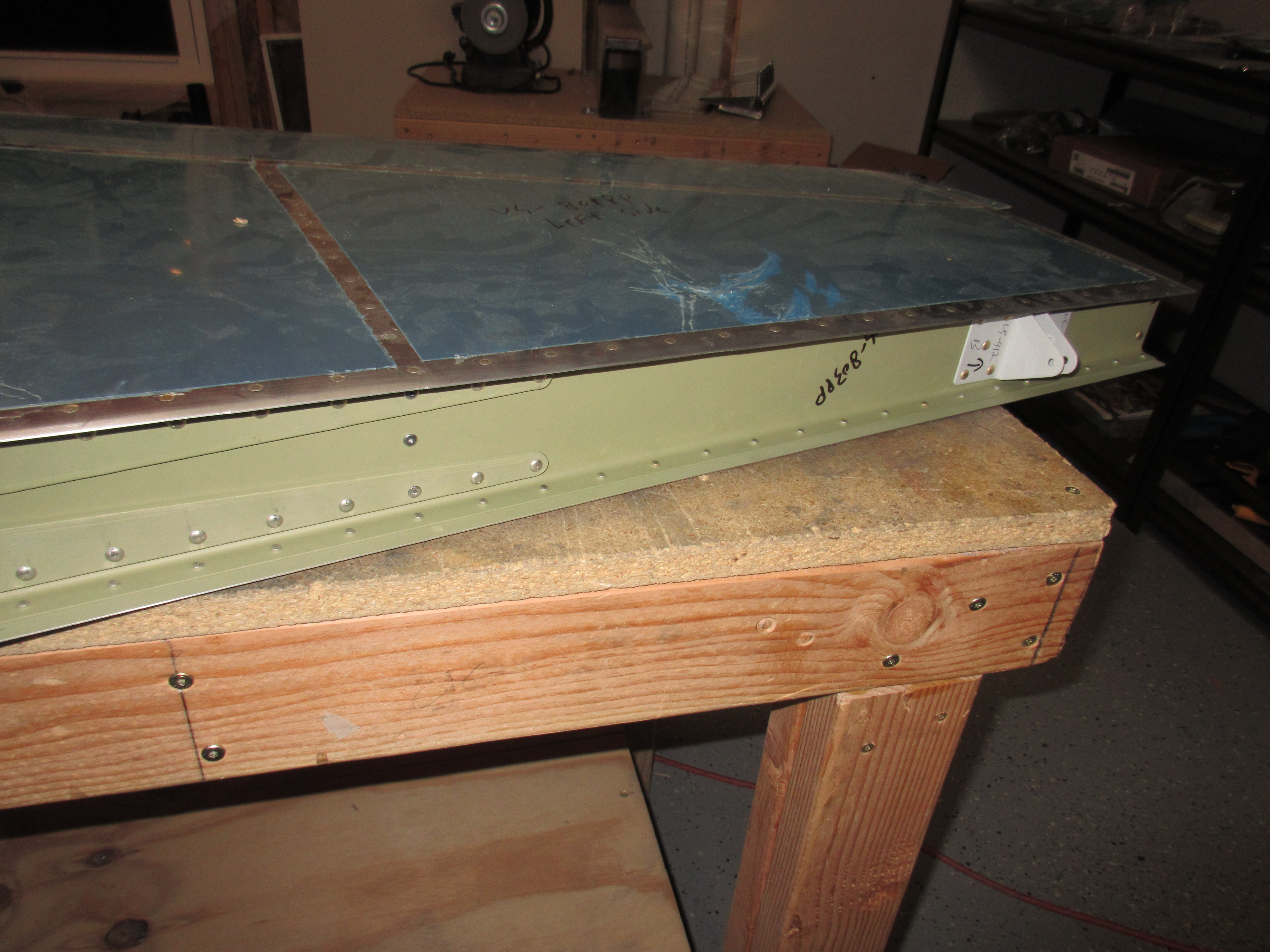
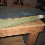
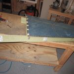
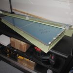
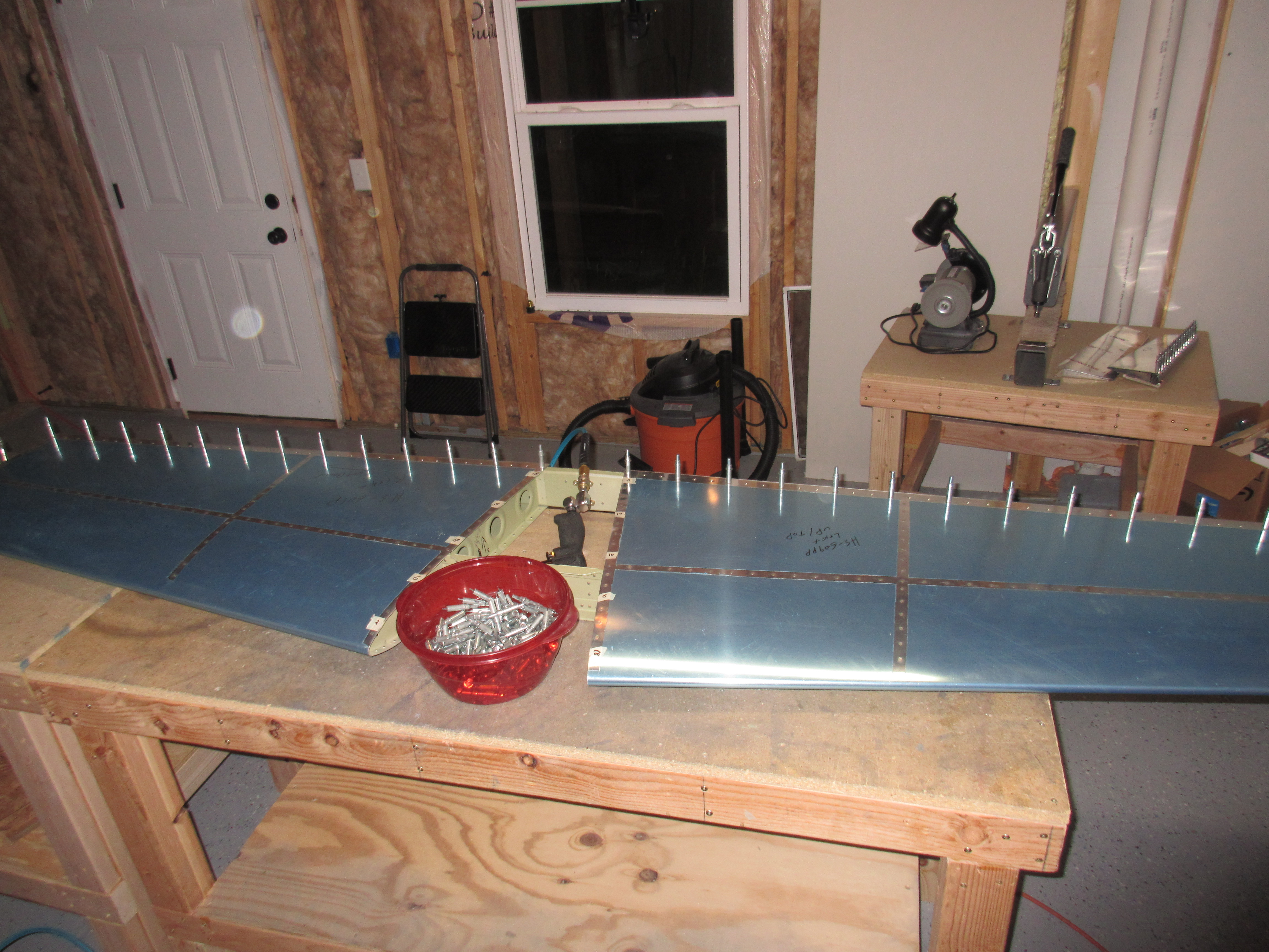
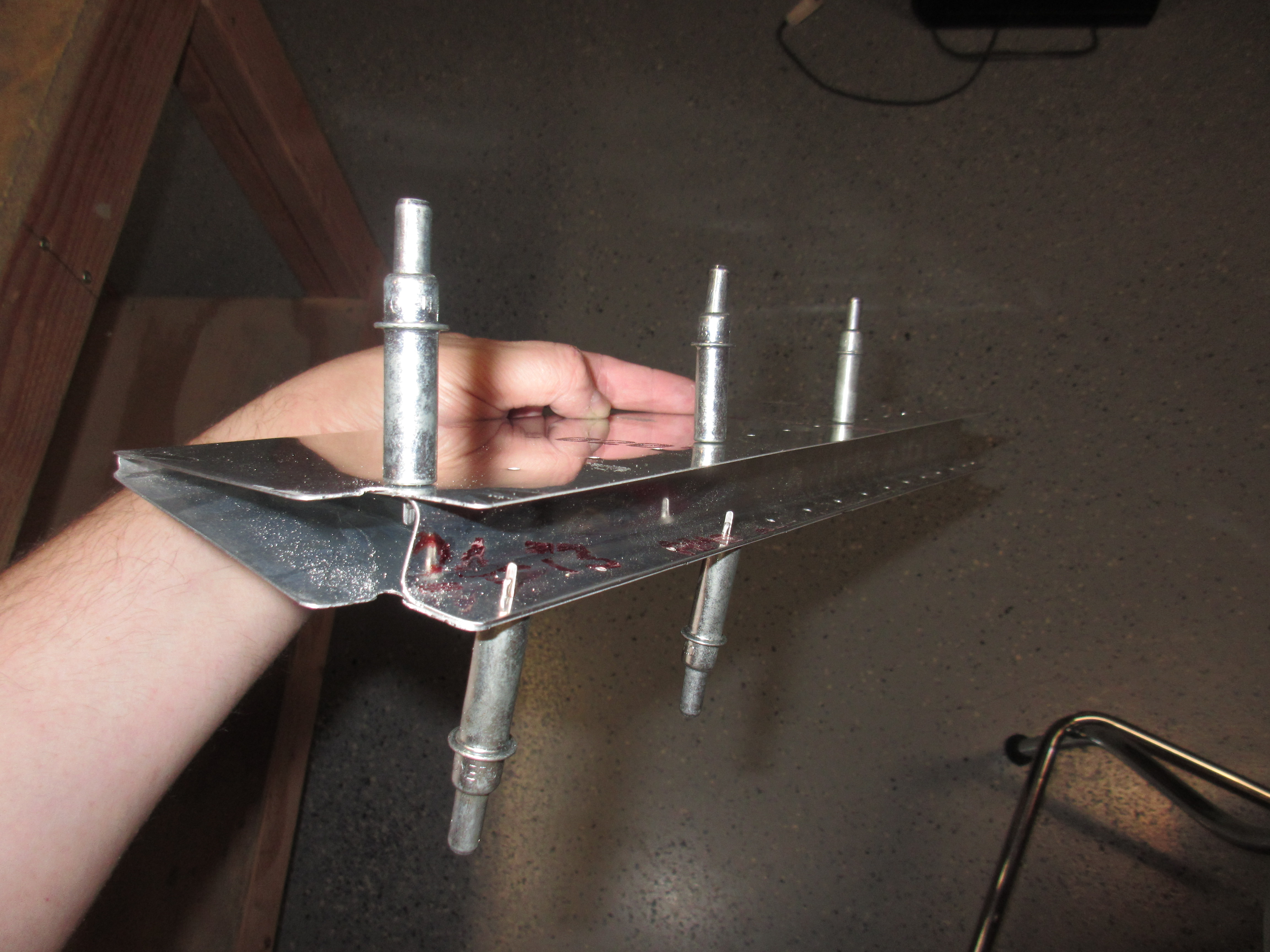
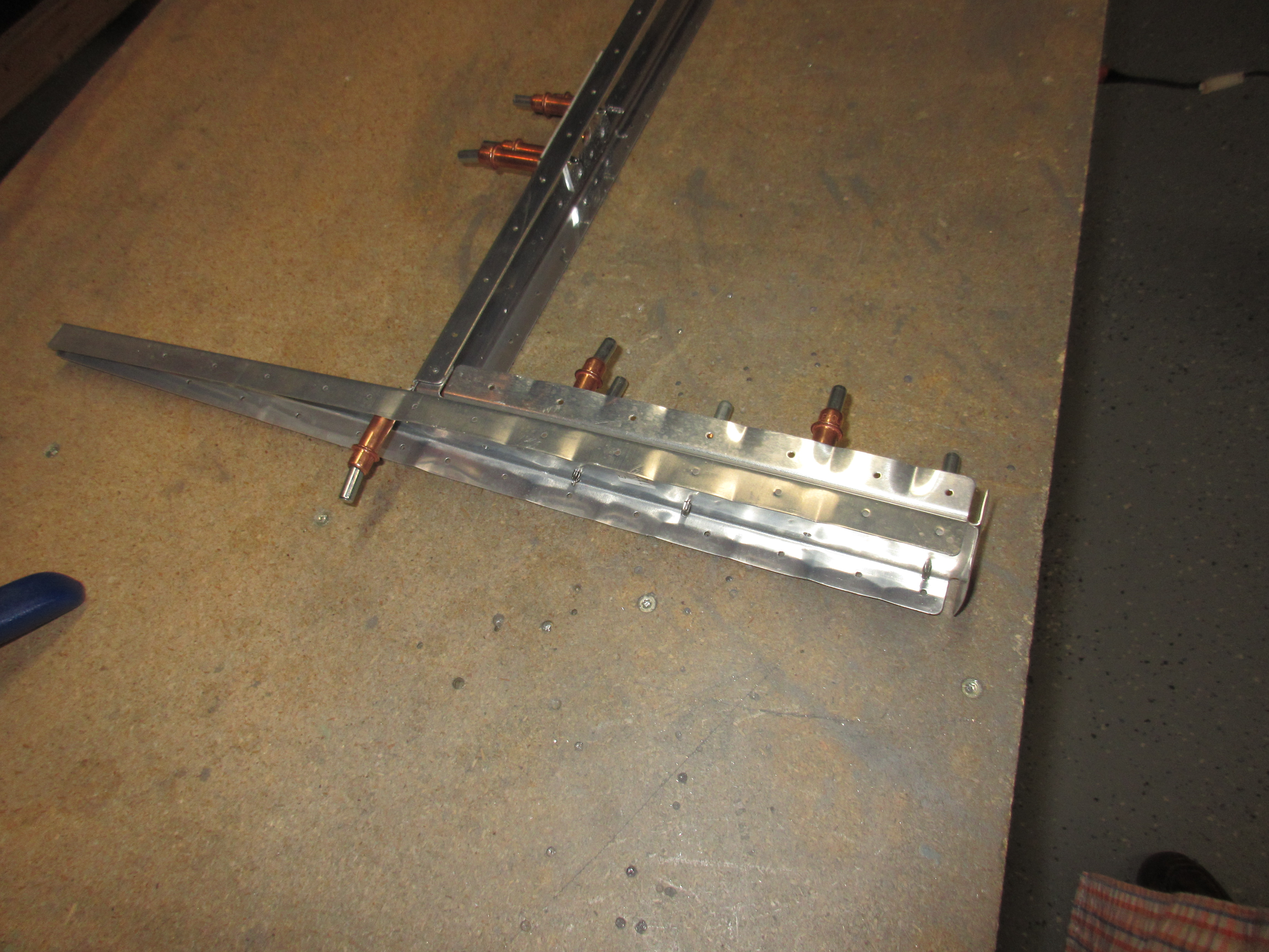
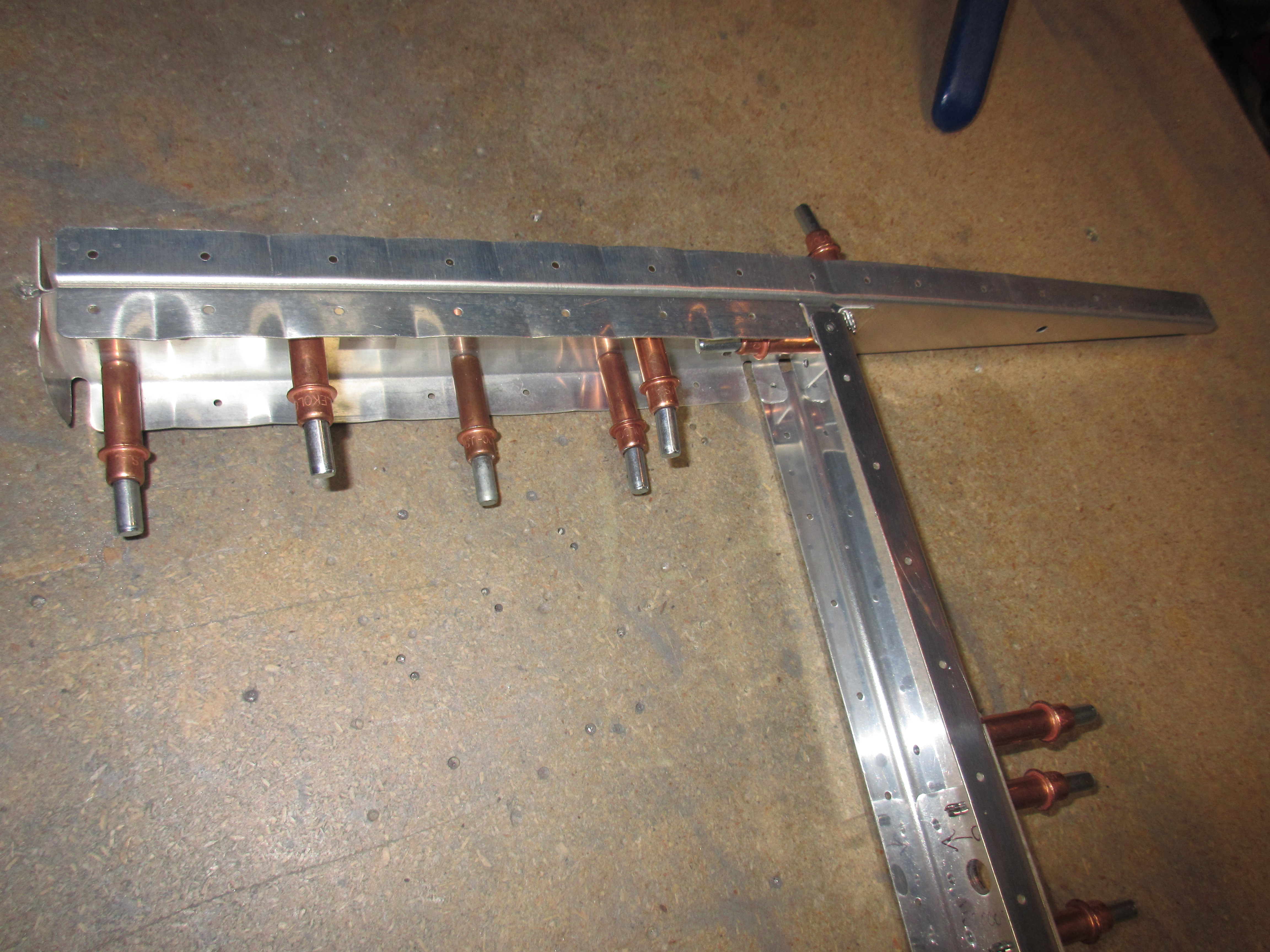
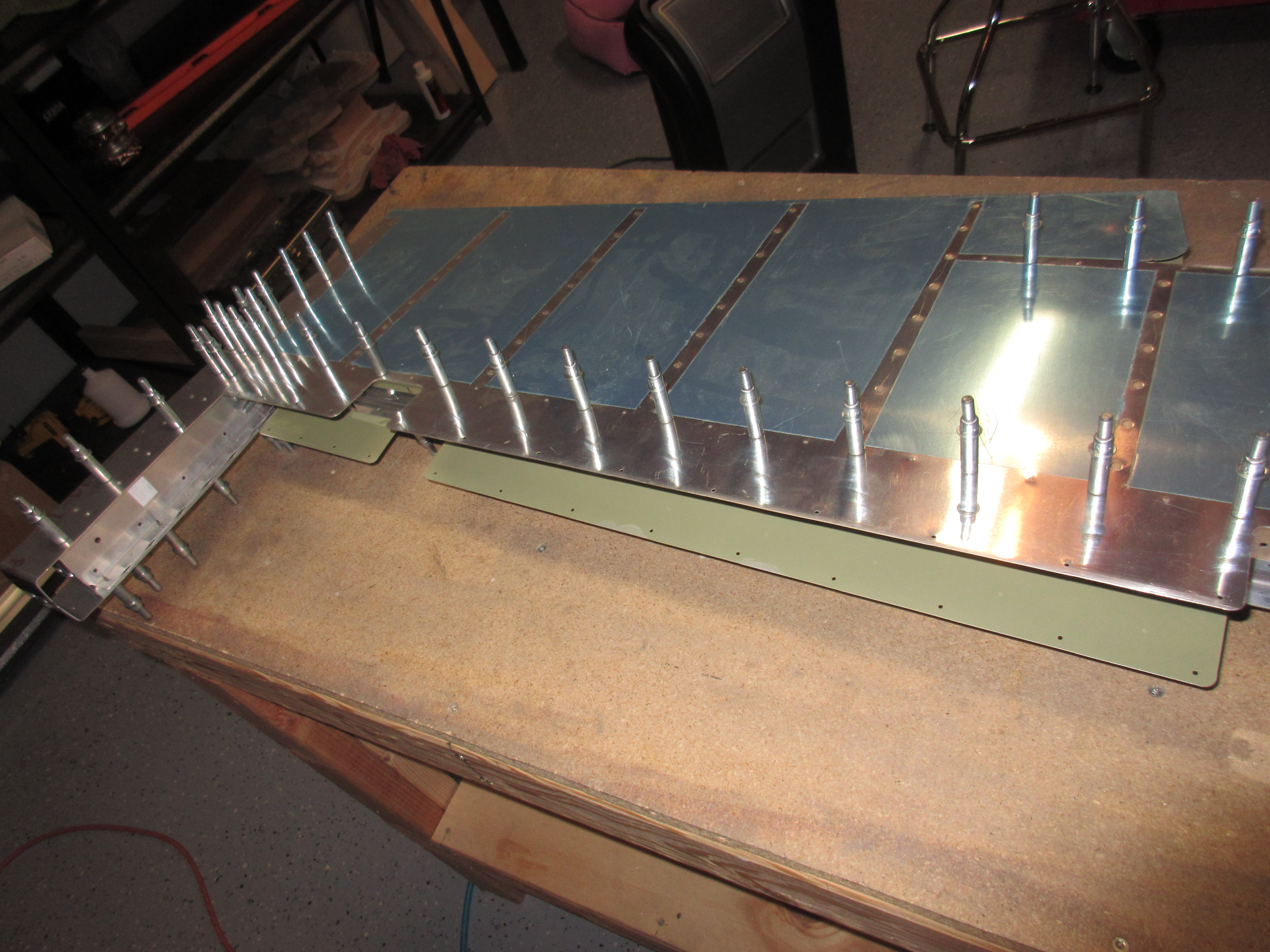
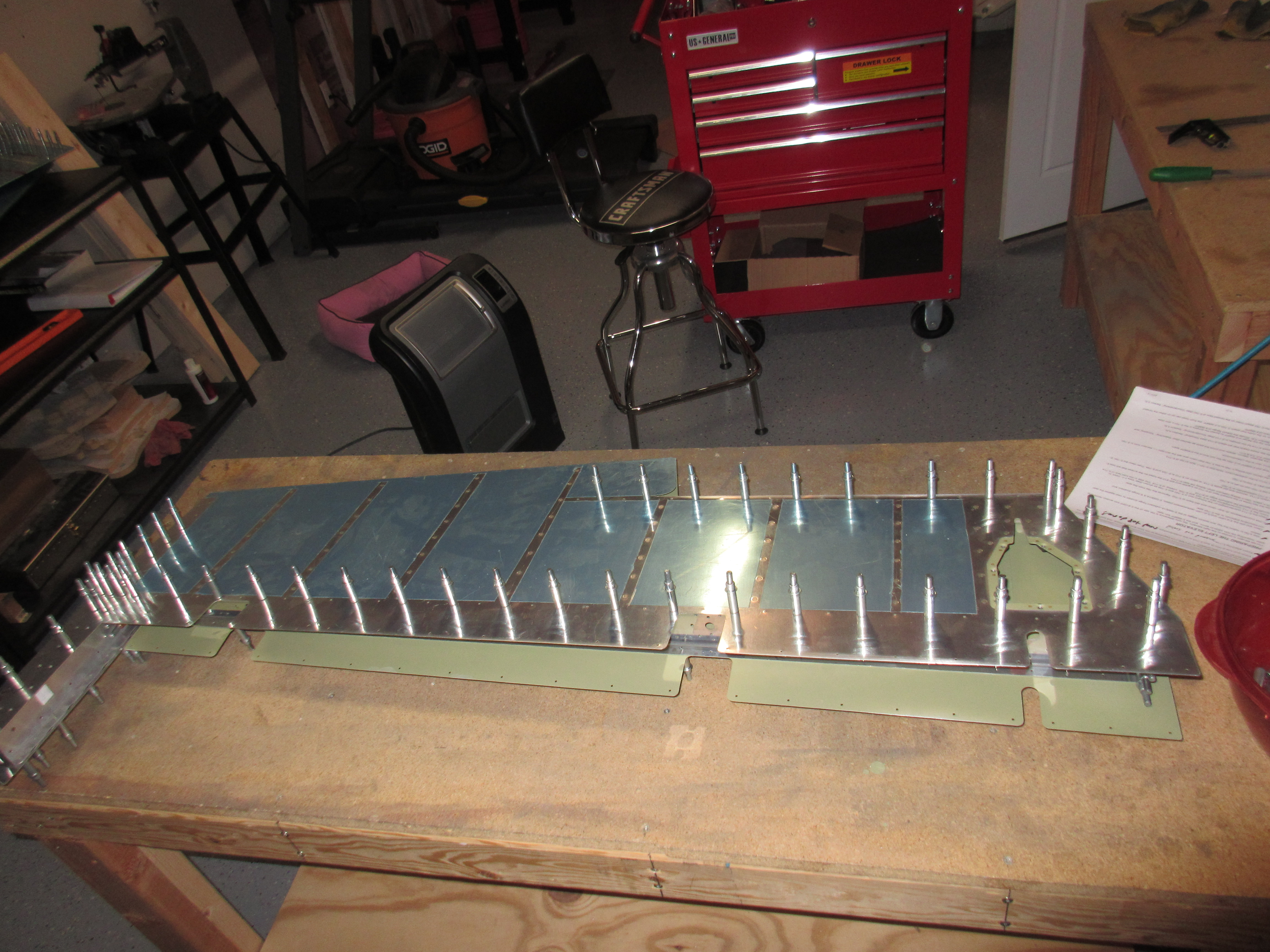
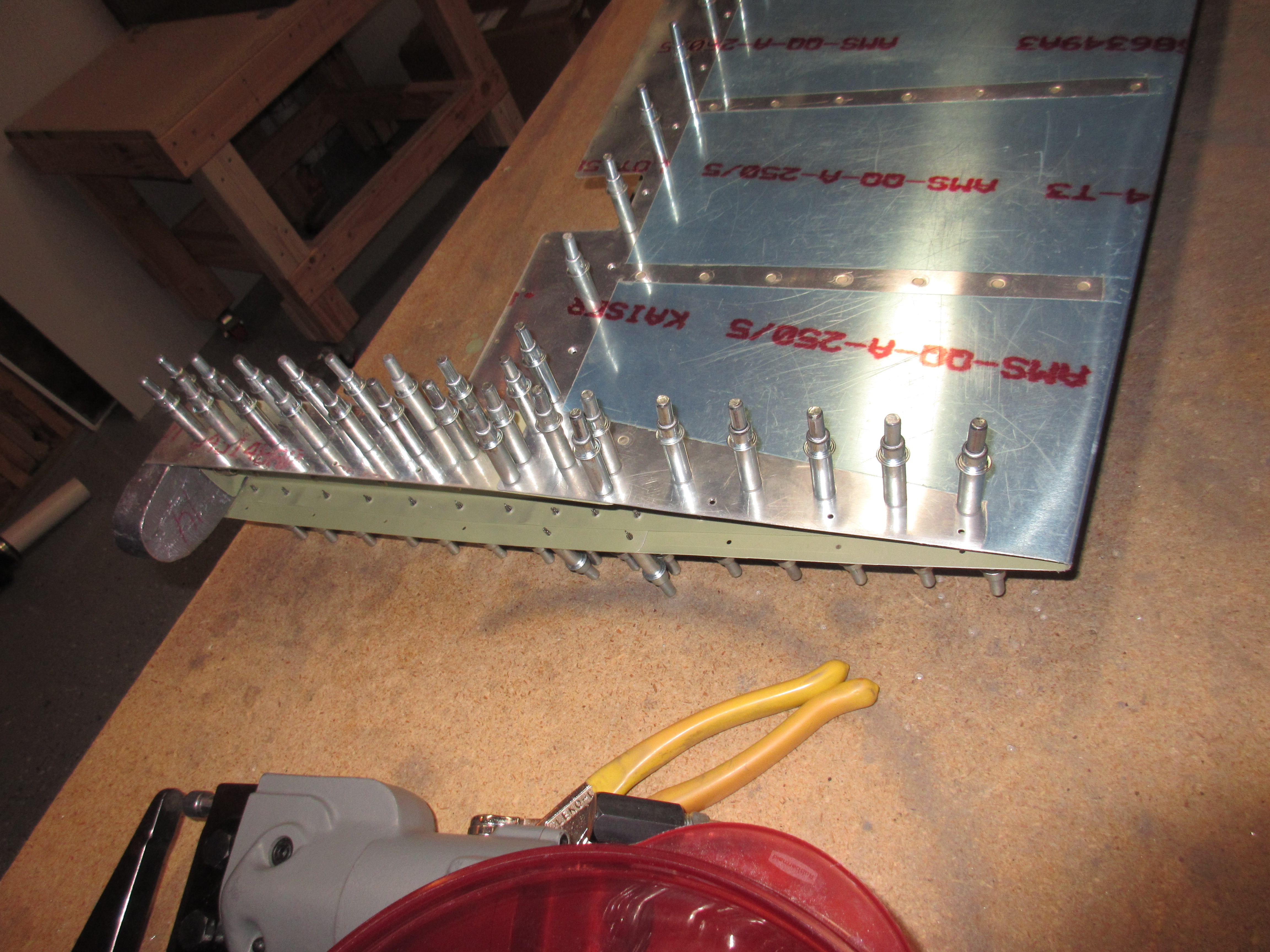
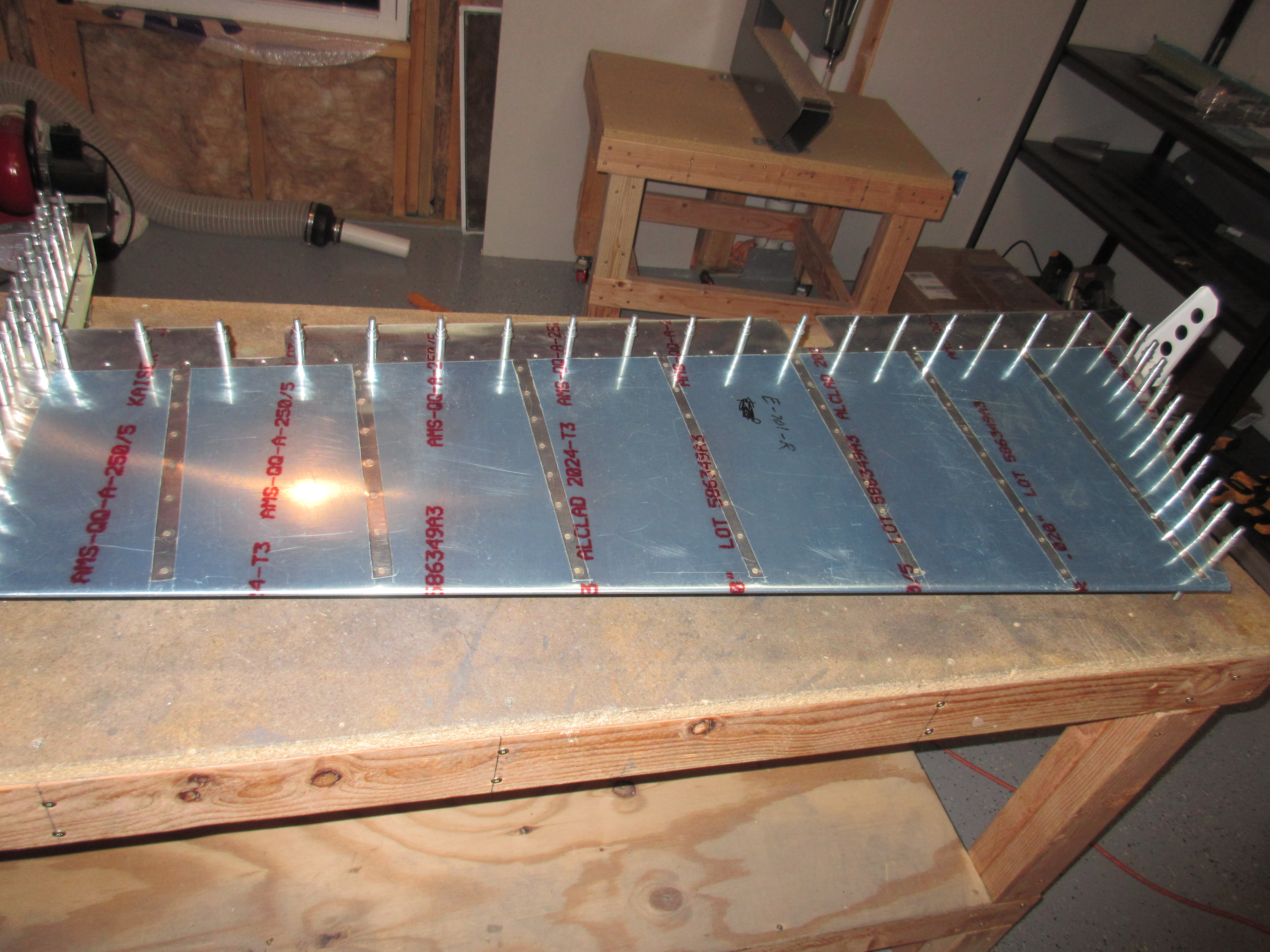
Now, its time to mate the skin with the skeleton, and cleco it all together for one last check before final riveting.  I gently inserted the skeleton into the skin, and lined everything up and clecoed every hole.  Once I had it all clecoed I used a straight edge against the skin to check its straightness, both on the stiffeners and between the stiffeners.  Then I removed every other cleco to make riveting easier.

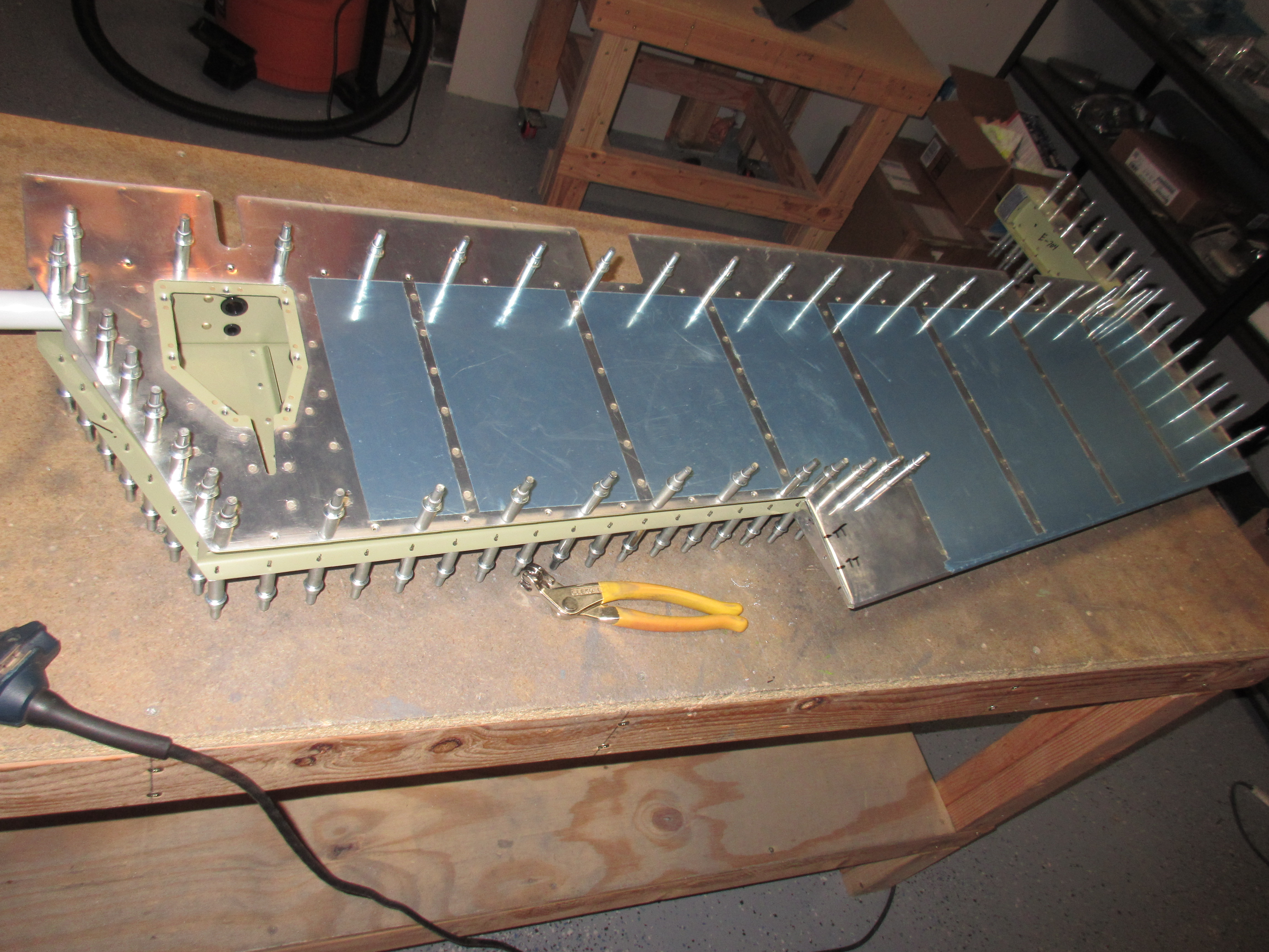
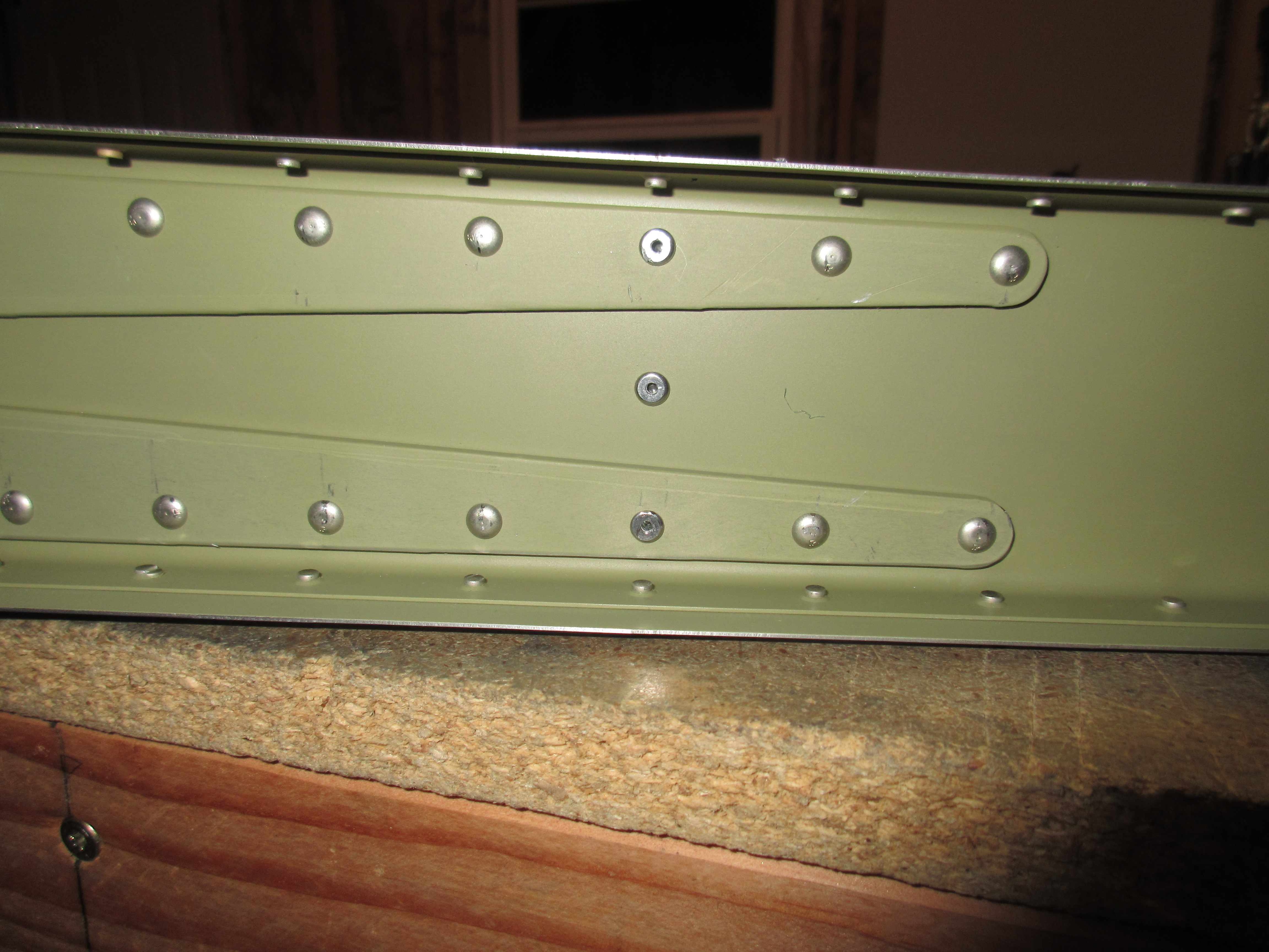
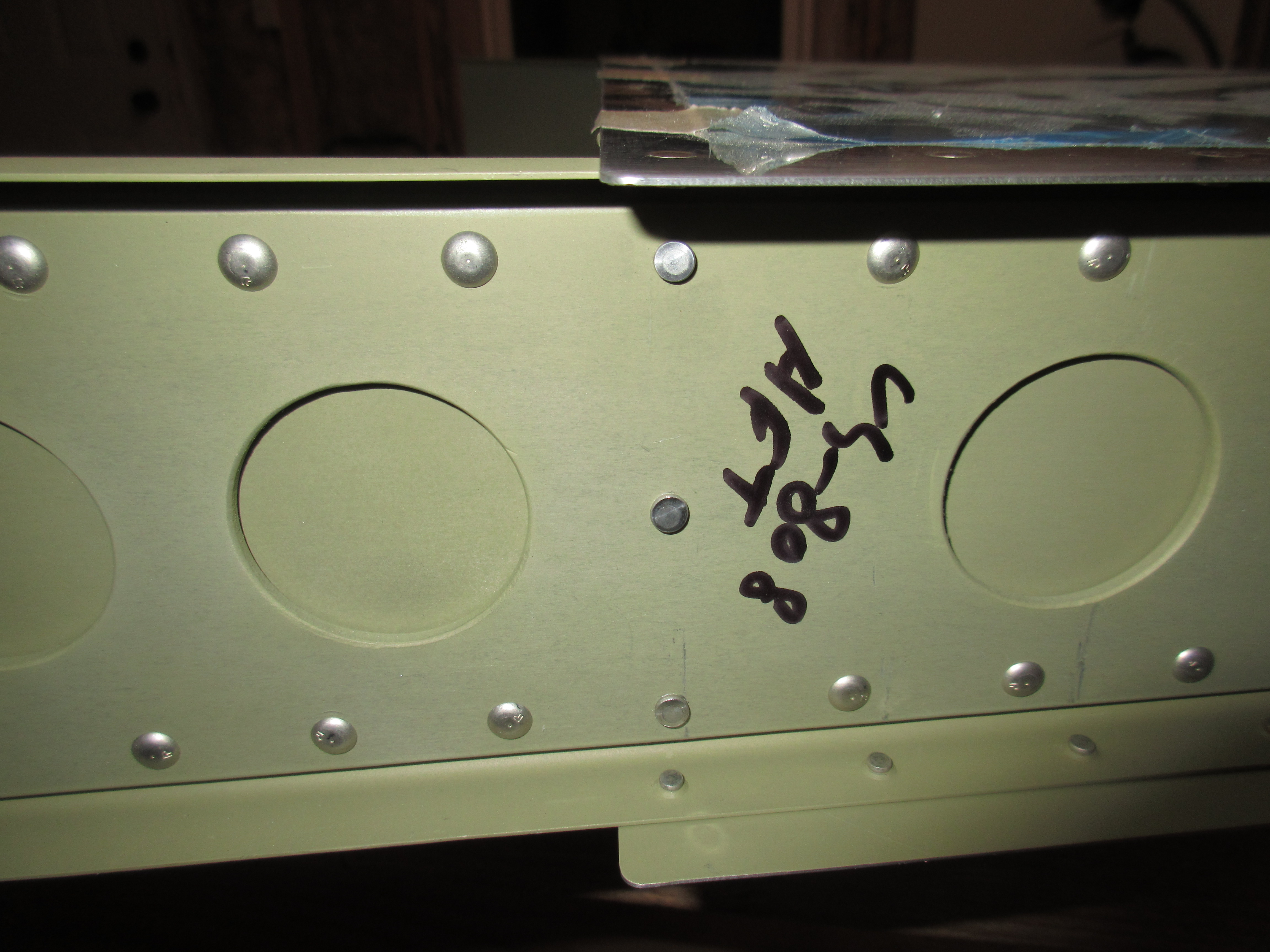
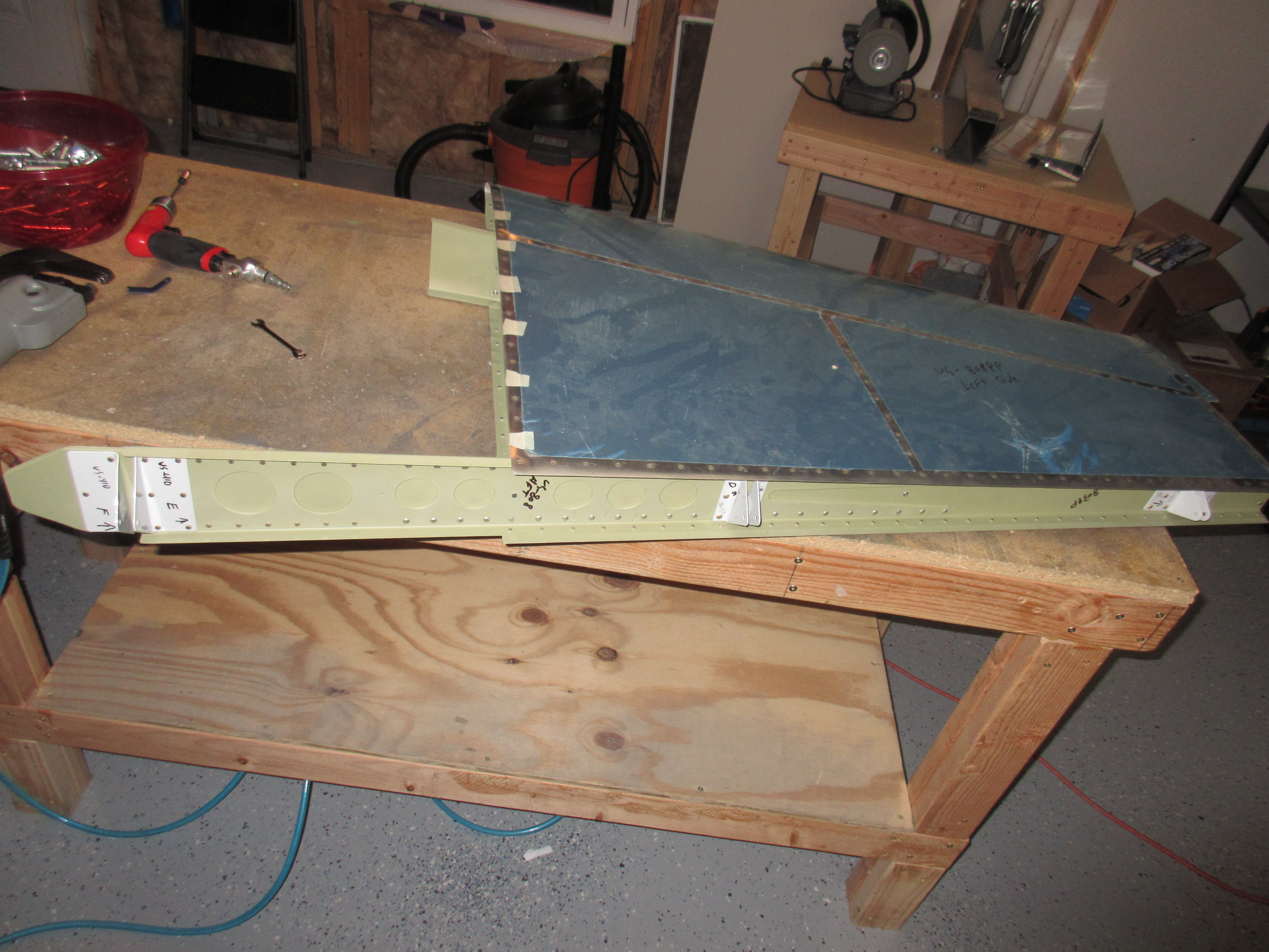
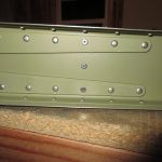
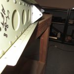
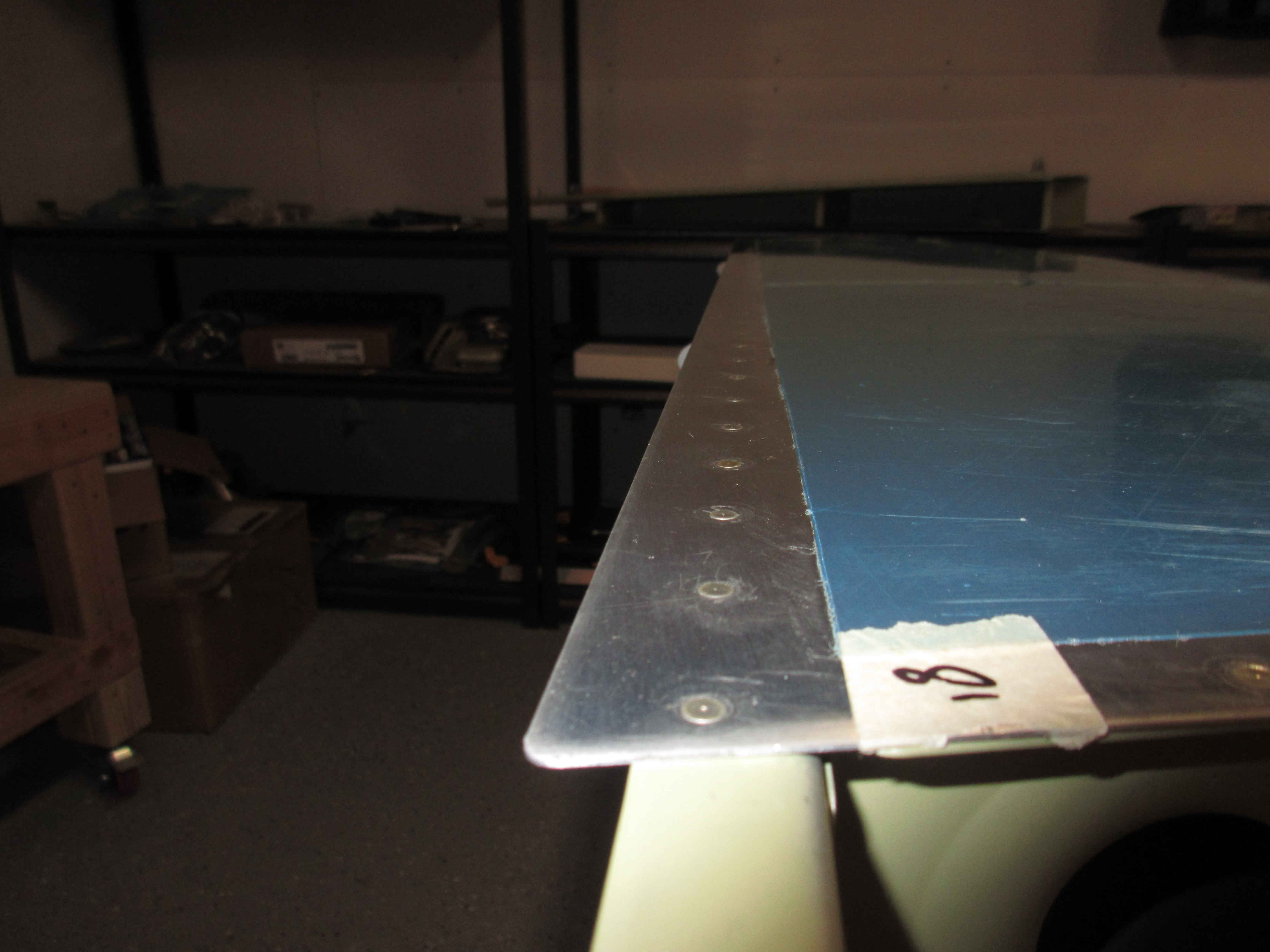
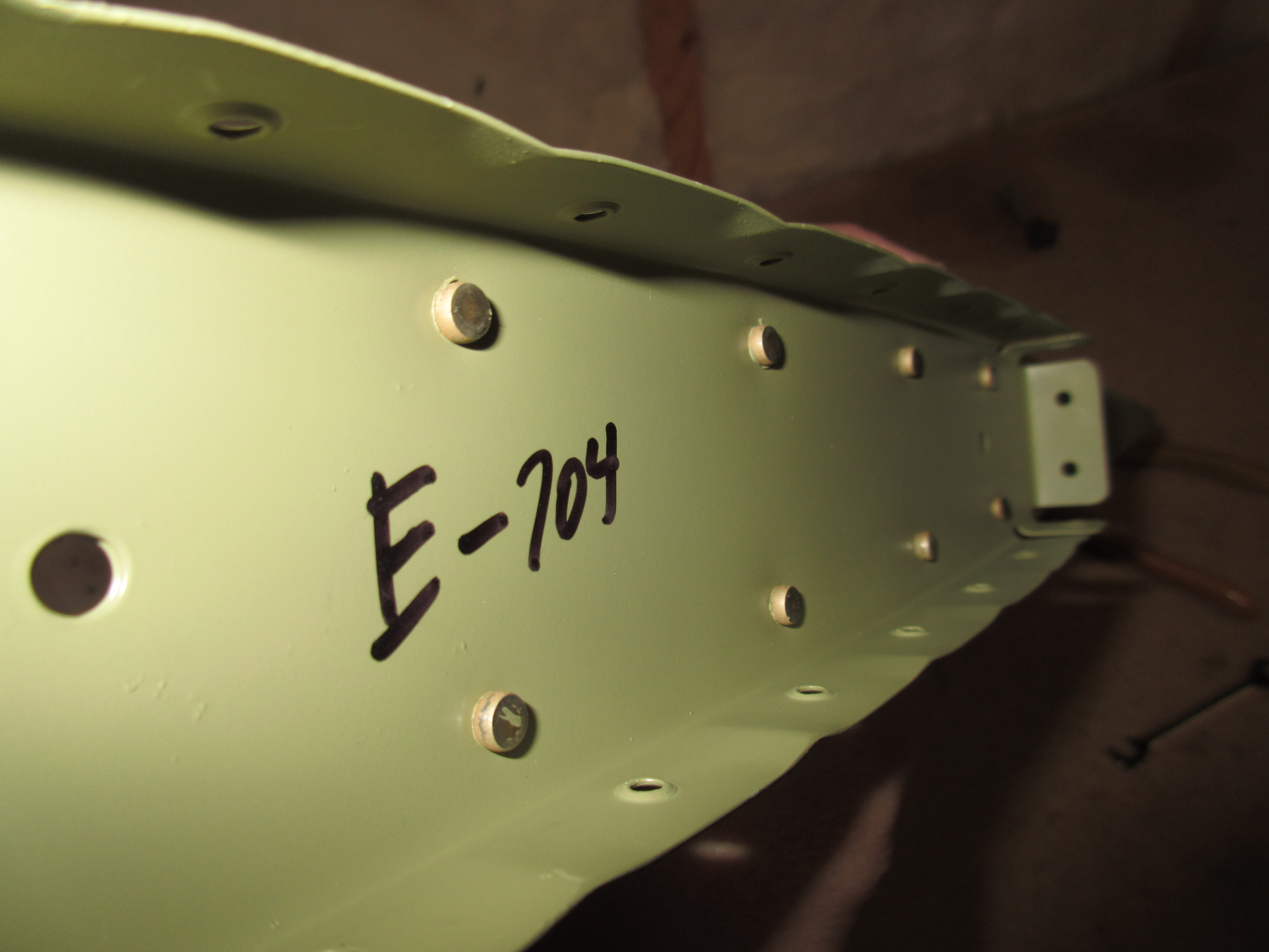
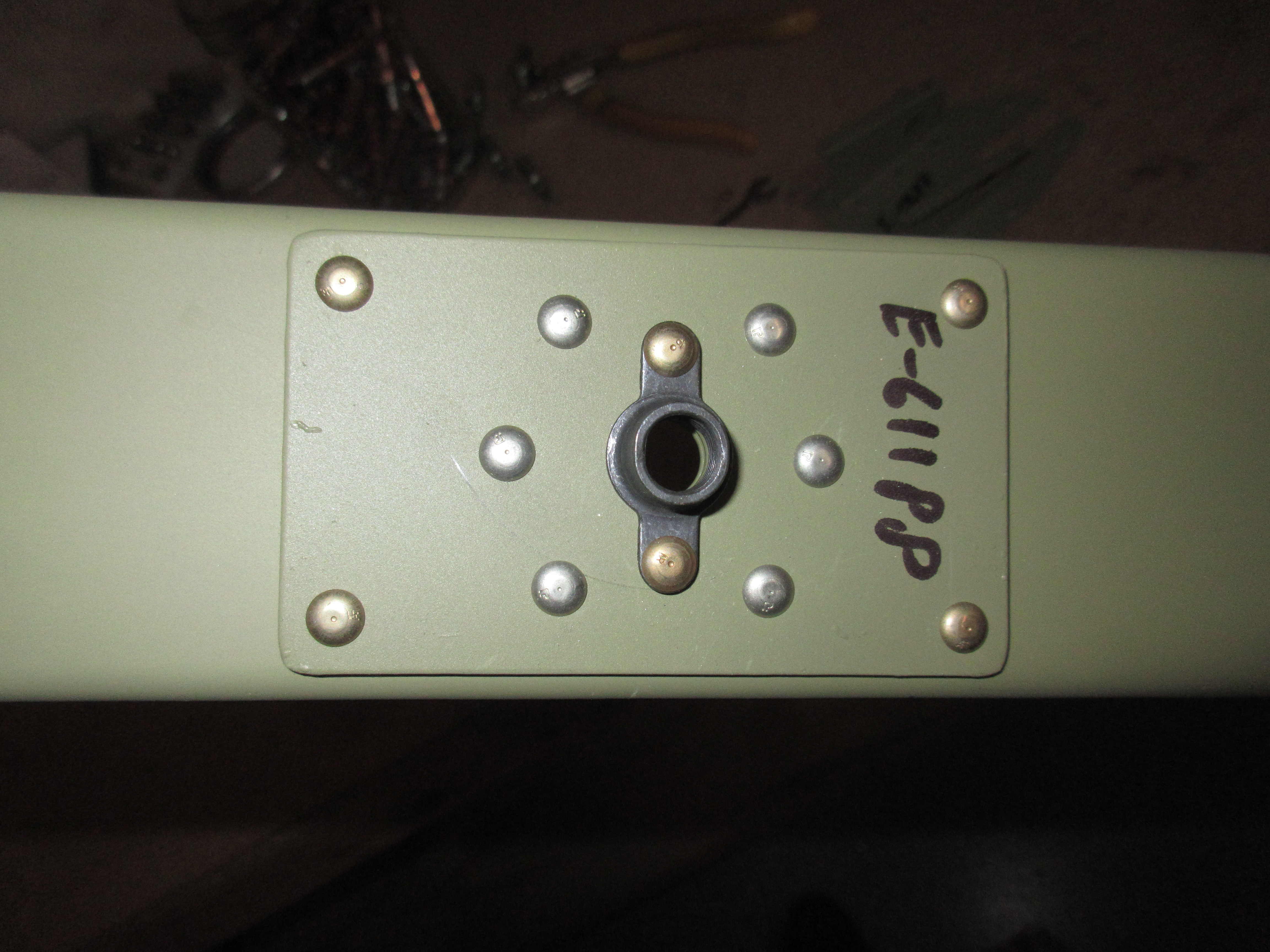
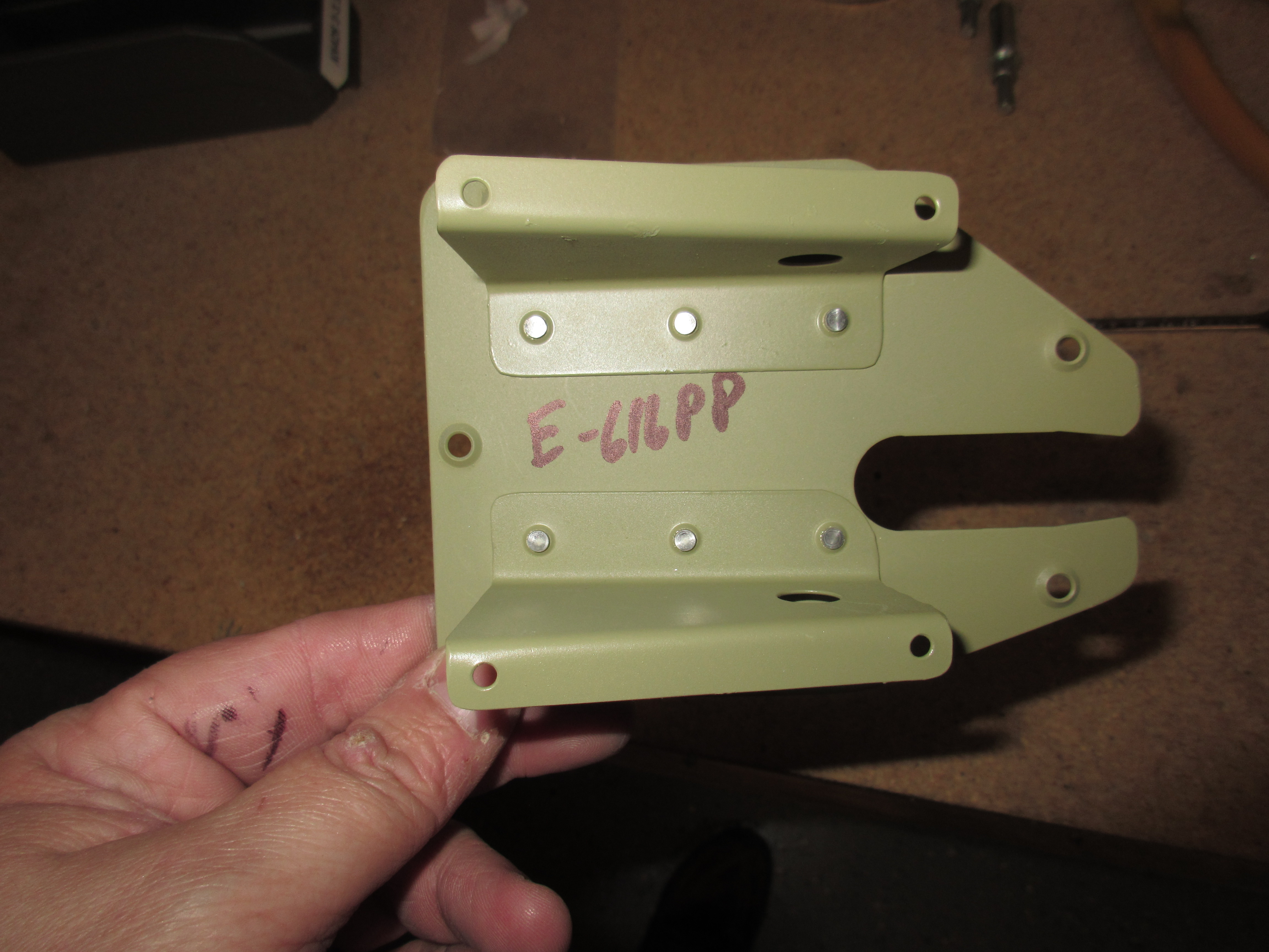
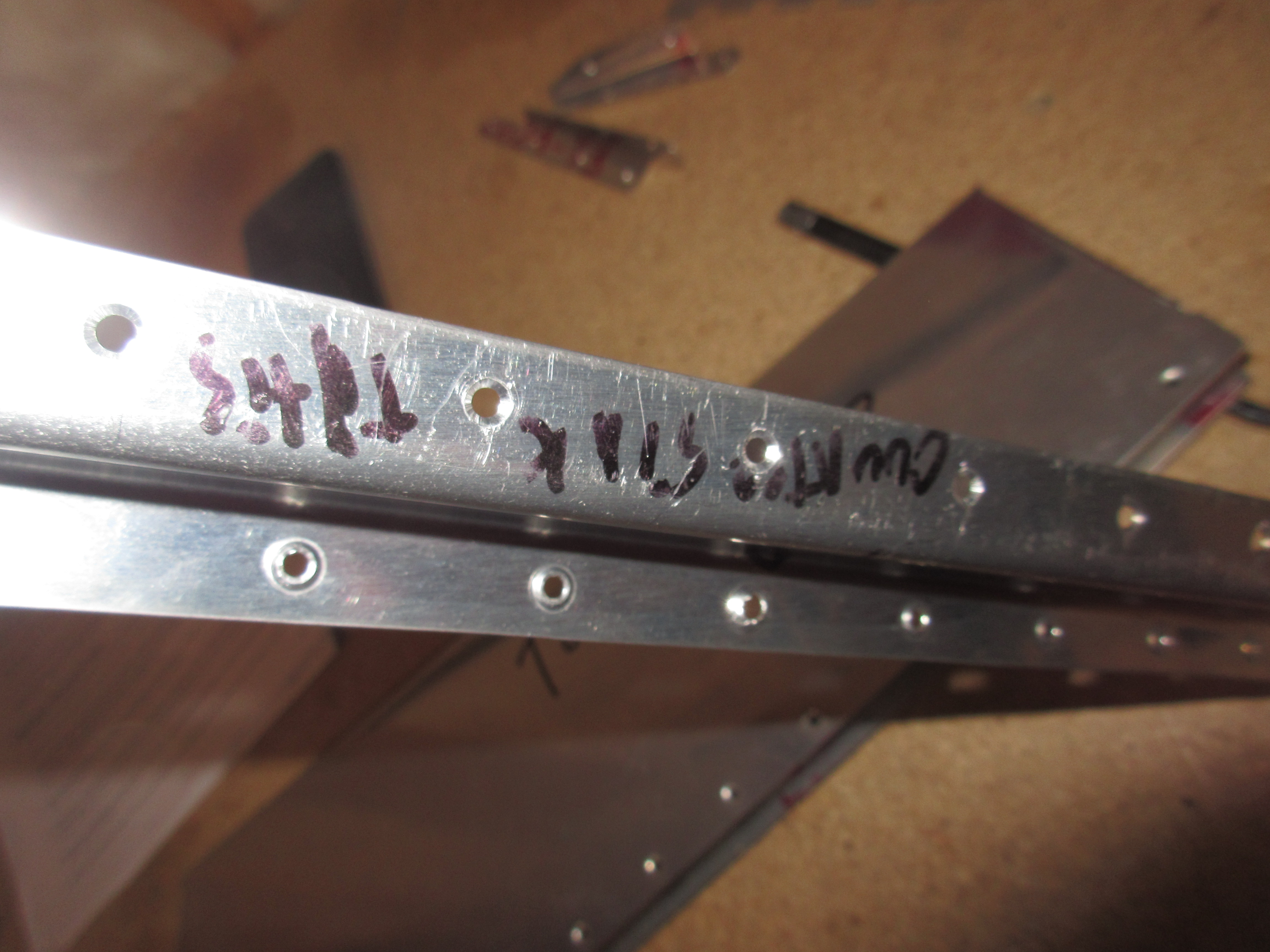
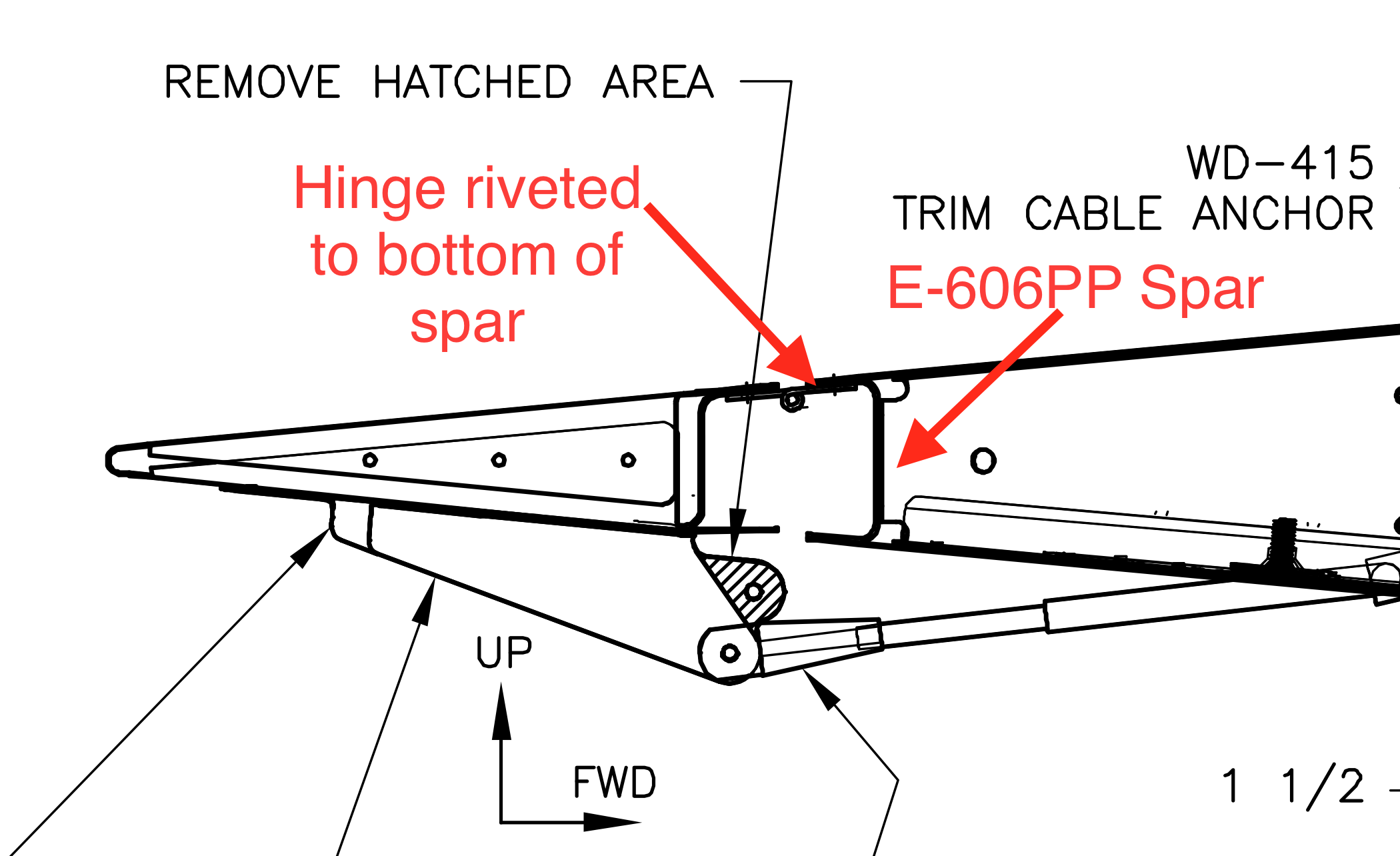
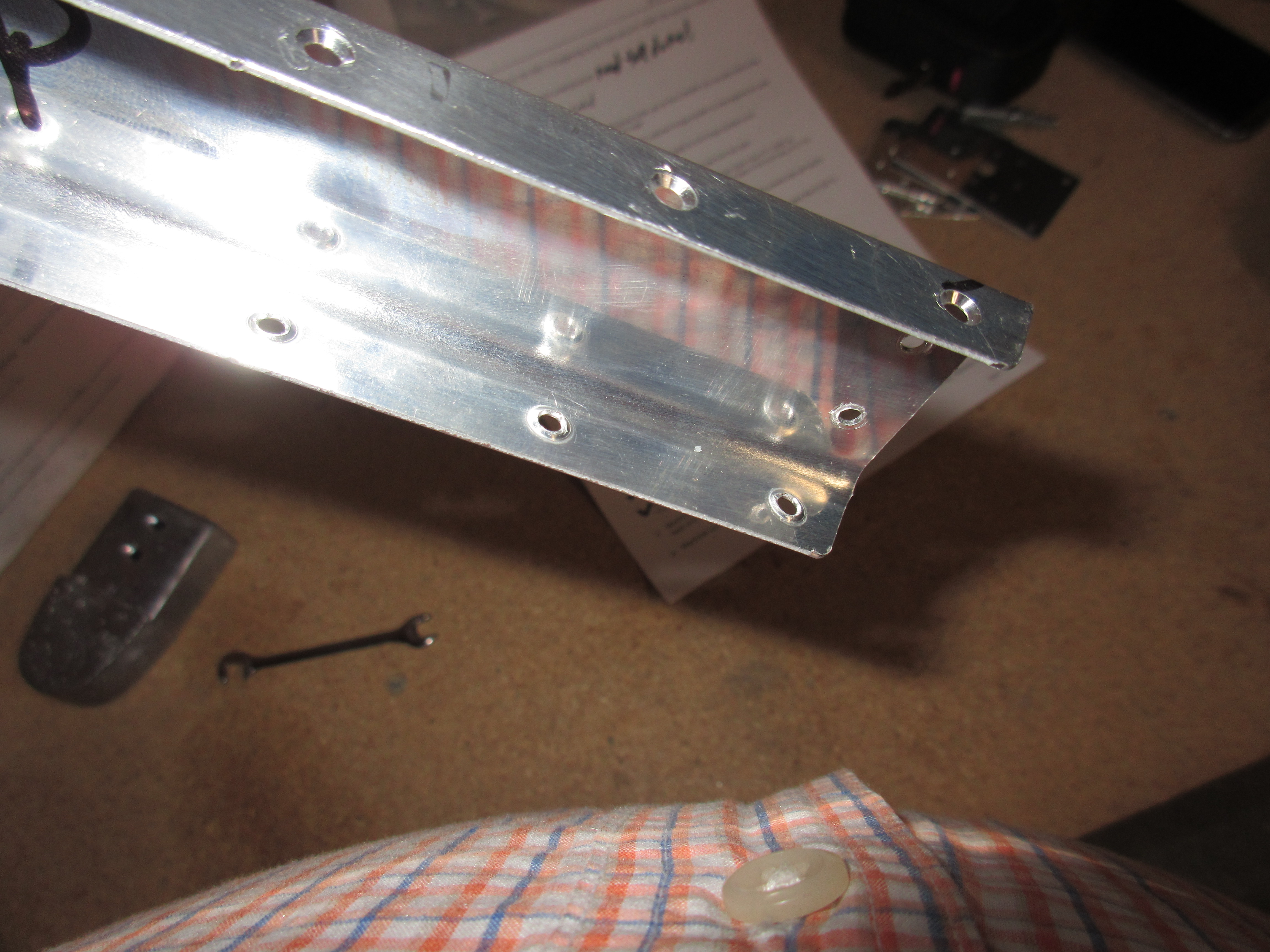
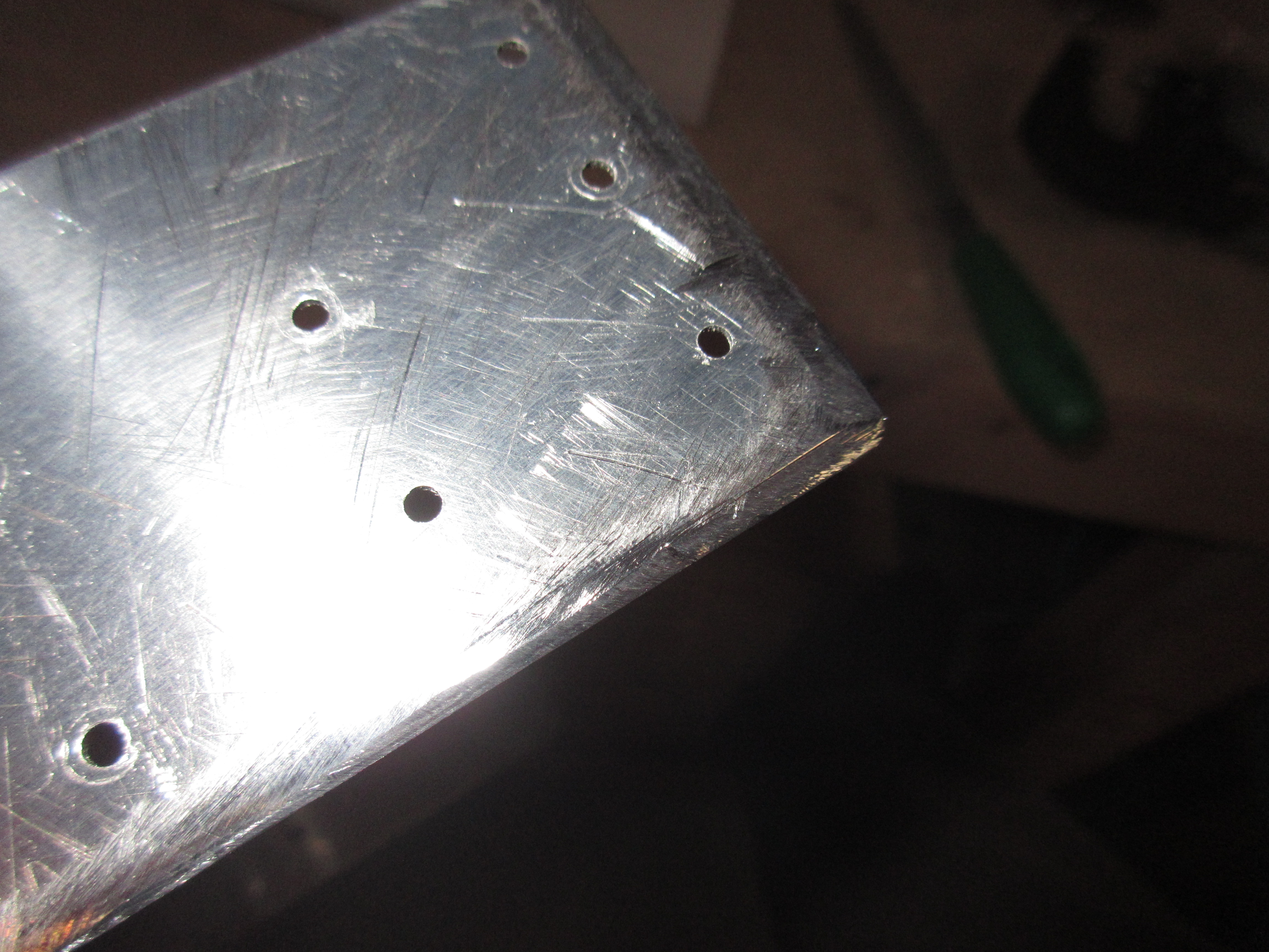
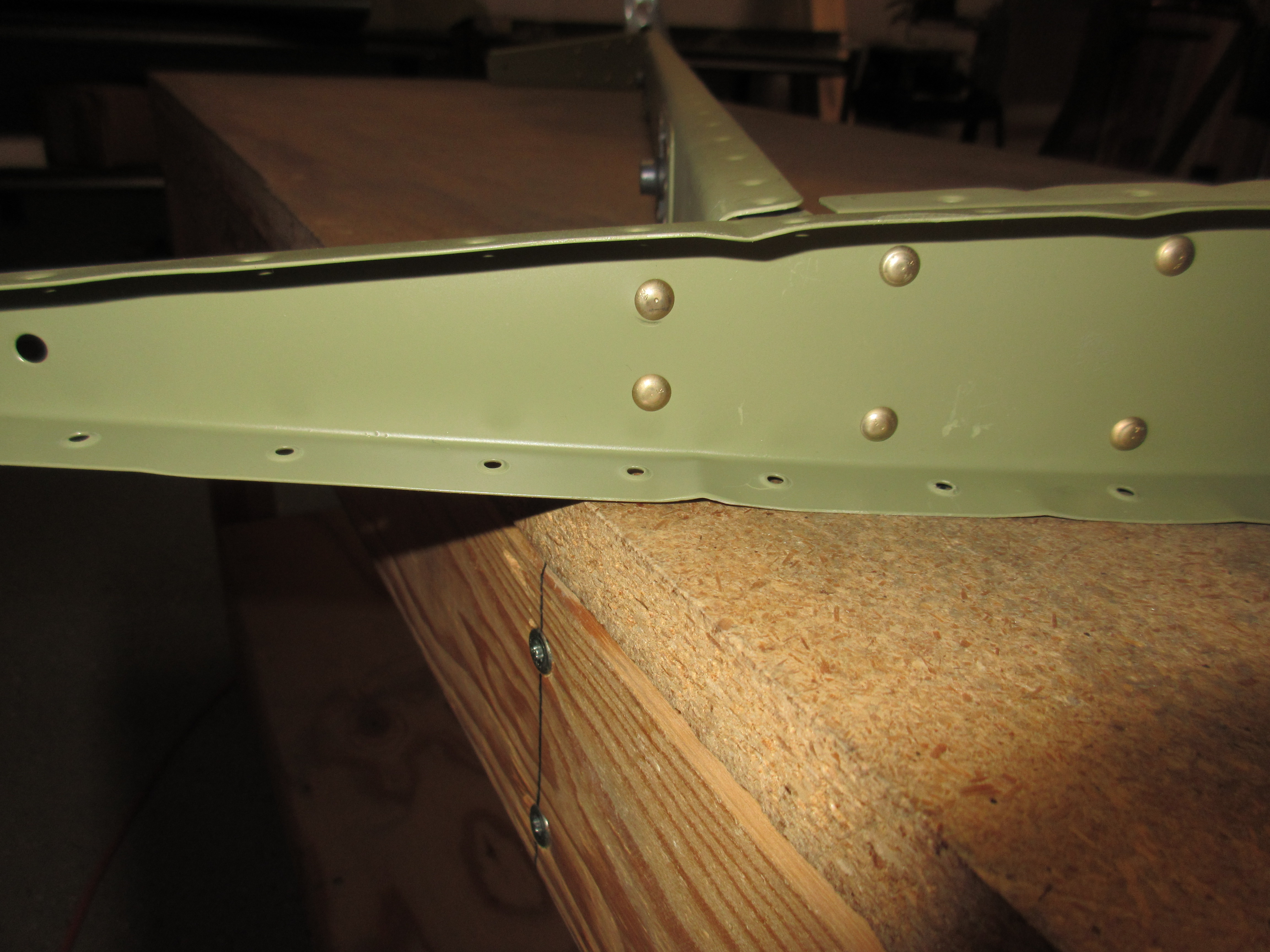
I only riveted the bottom skin for now.  I will leave the top skin free so I can put pro-seal on the stiffener ends before closing it up for good.  I closed the bottom skin by inserting a rivet in every other hole and squeezing it.  Then I removed the clecos, and clecoed the holes they were in. On the left elevator we have to use 4 blind rivets on the outboard end of the E-606PP spar, as there is no way to get to it otherwise. I used MK319BS blind rivets in those last 4 holes, and made sure they were sitting as flush as possible.  They were not 100% flush like the AN426 rivets, but they ended up flush enough to make me happy.

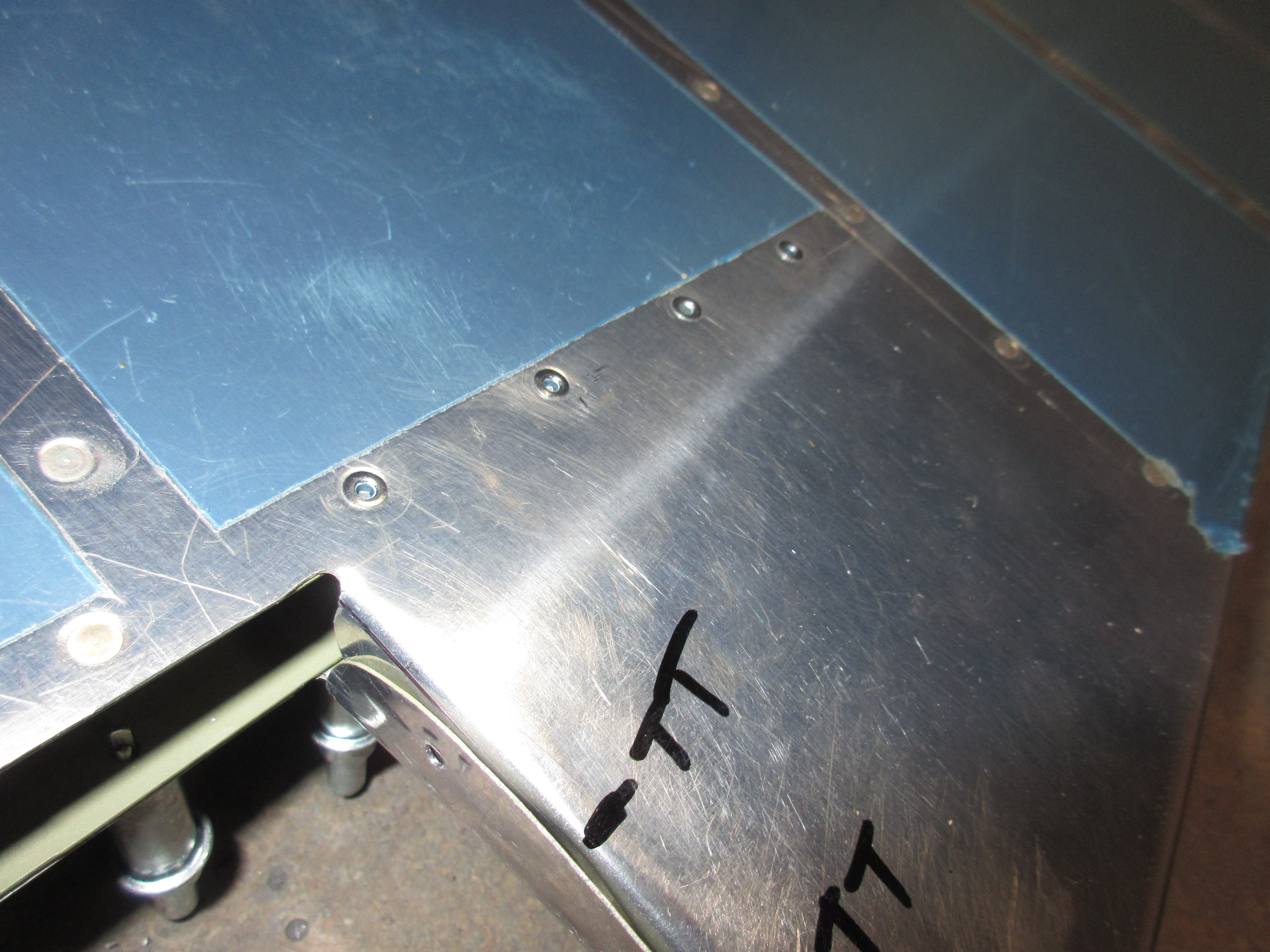
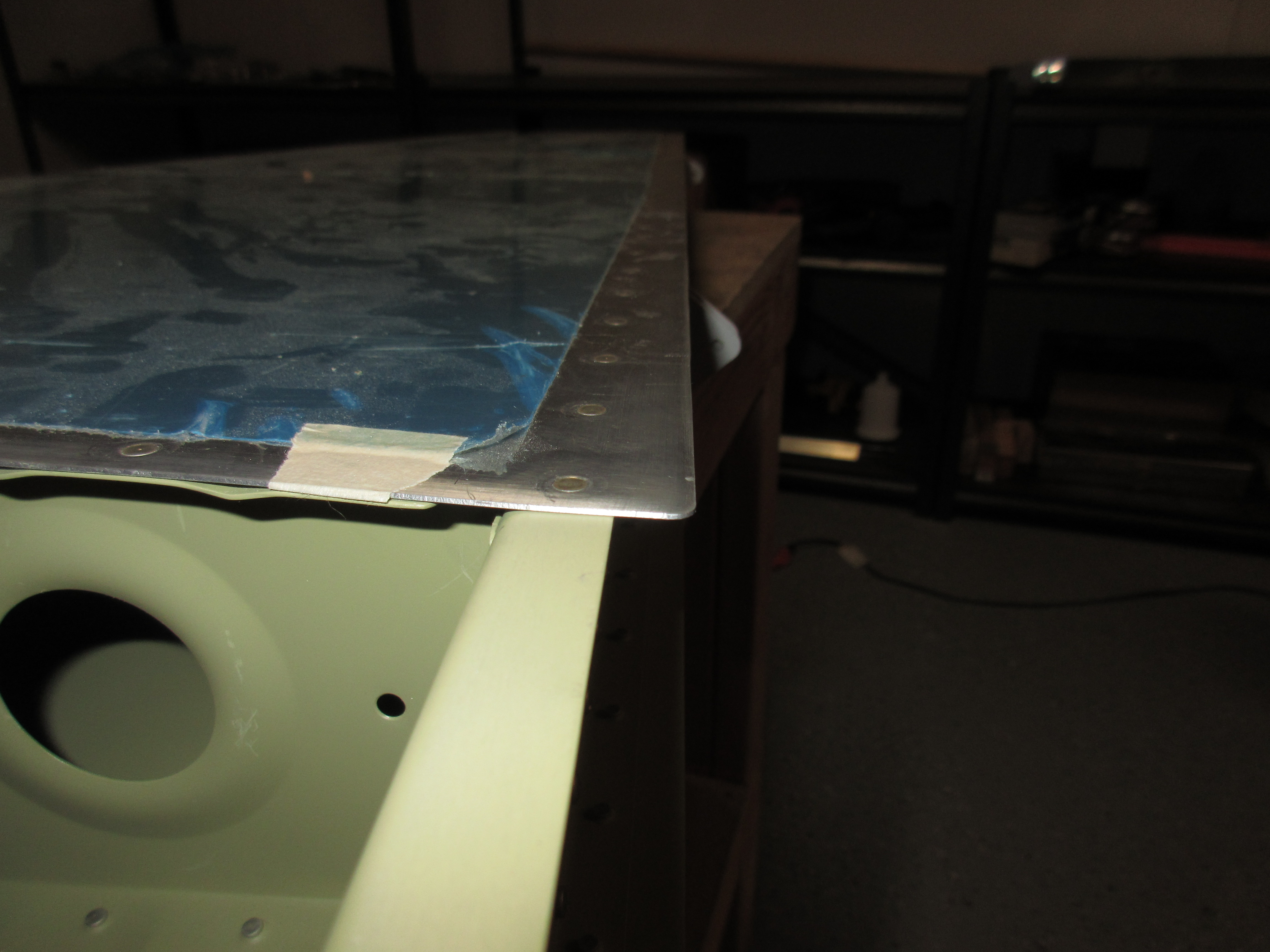
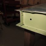
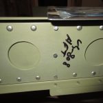
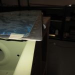
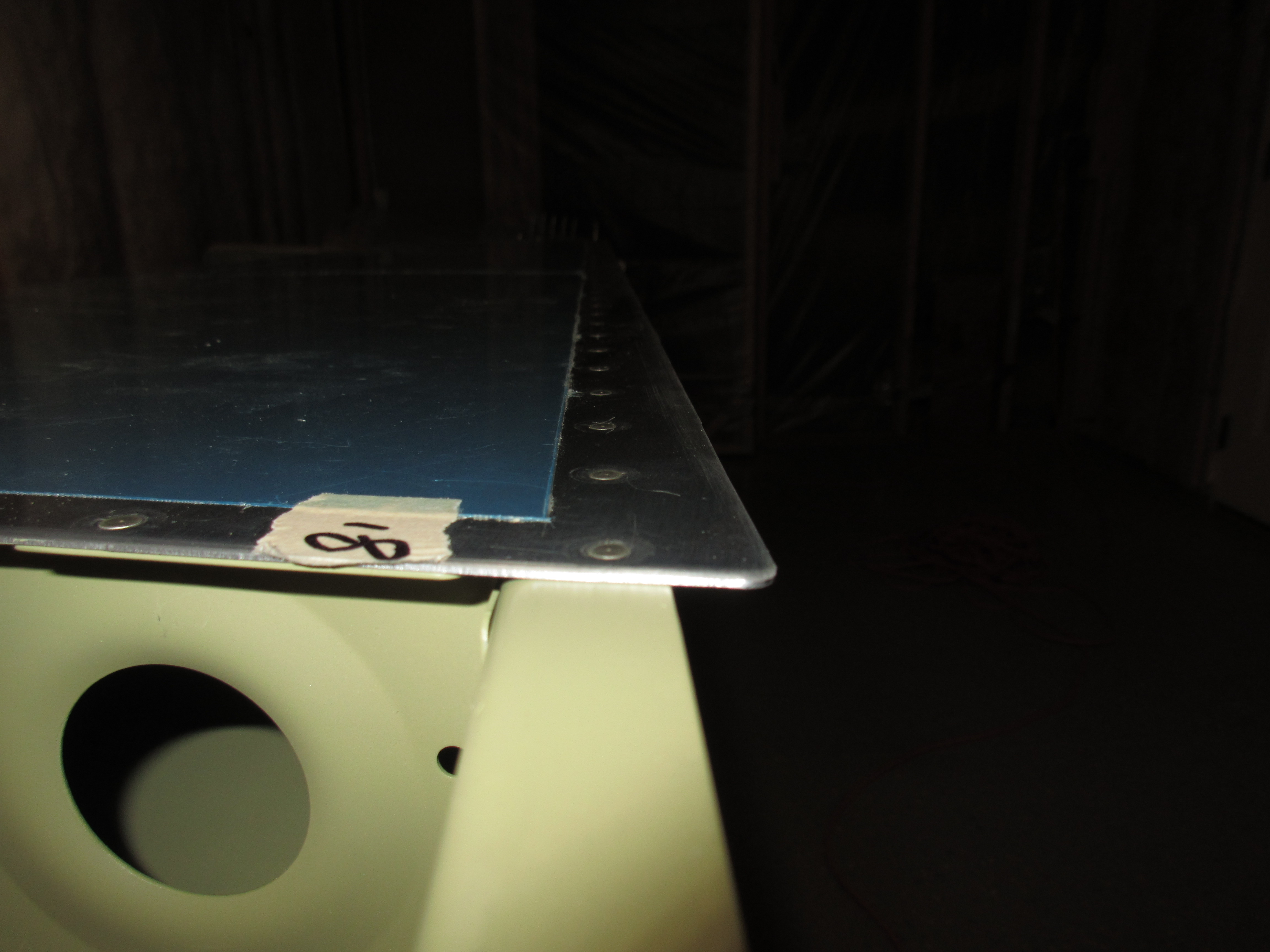
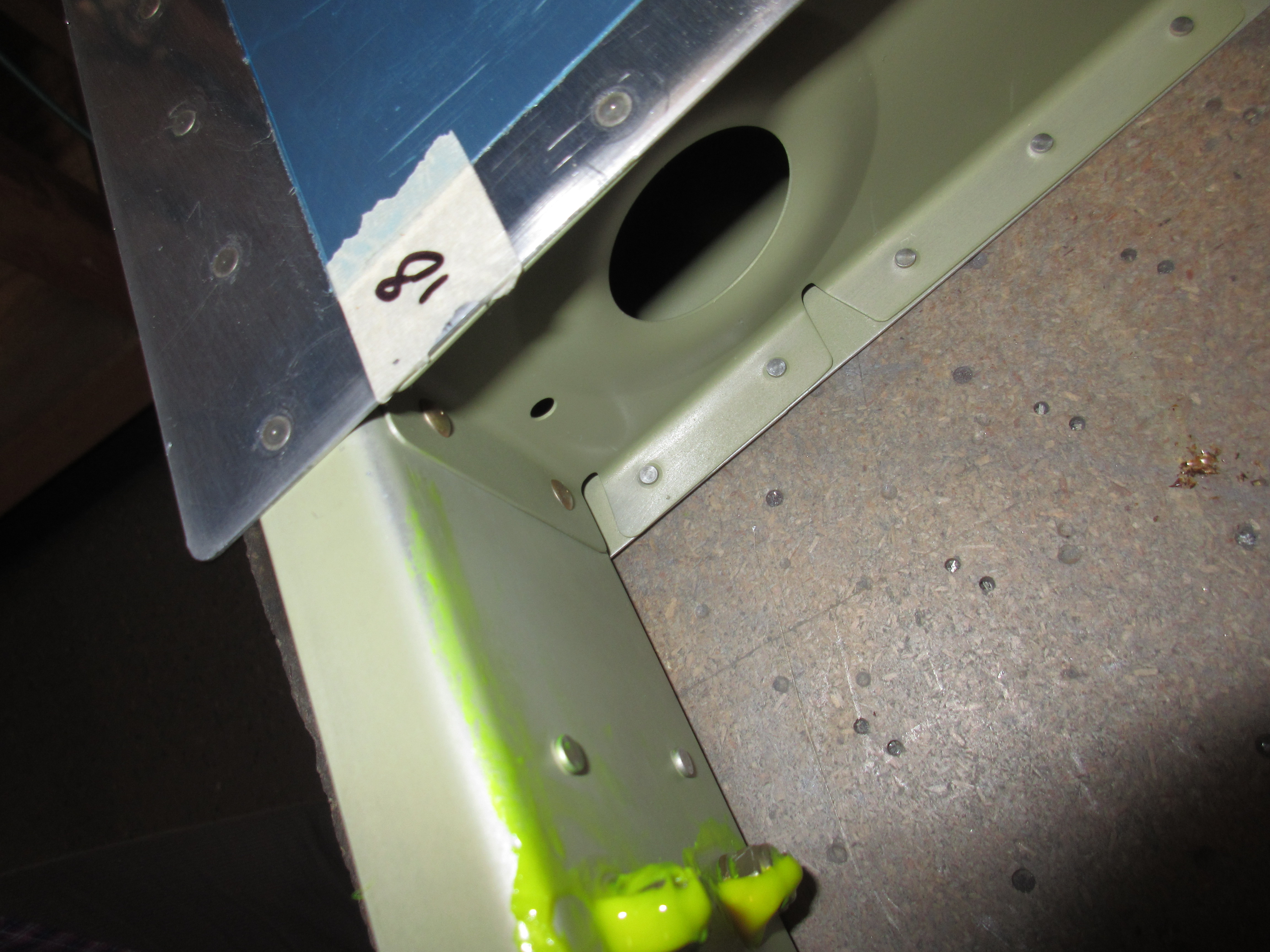
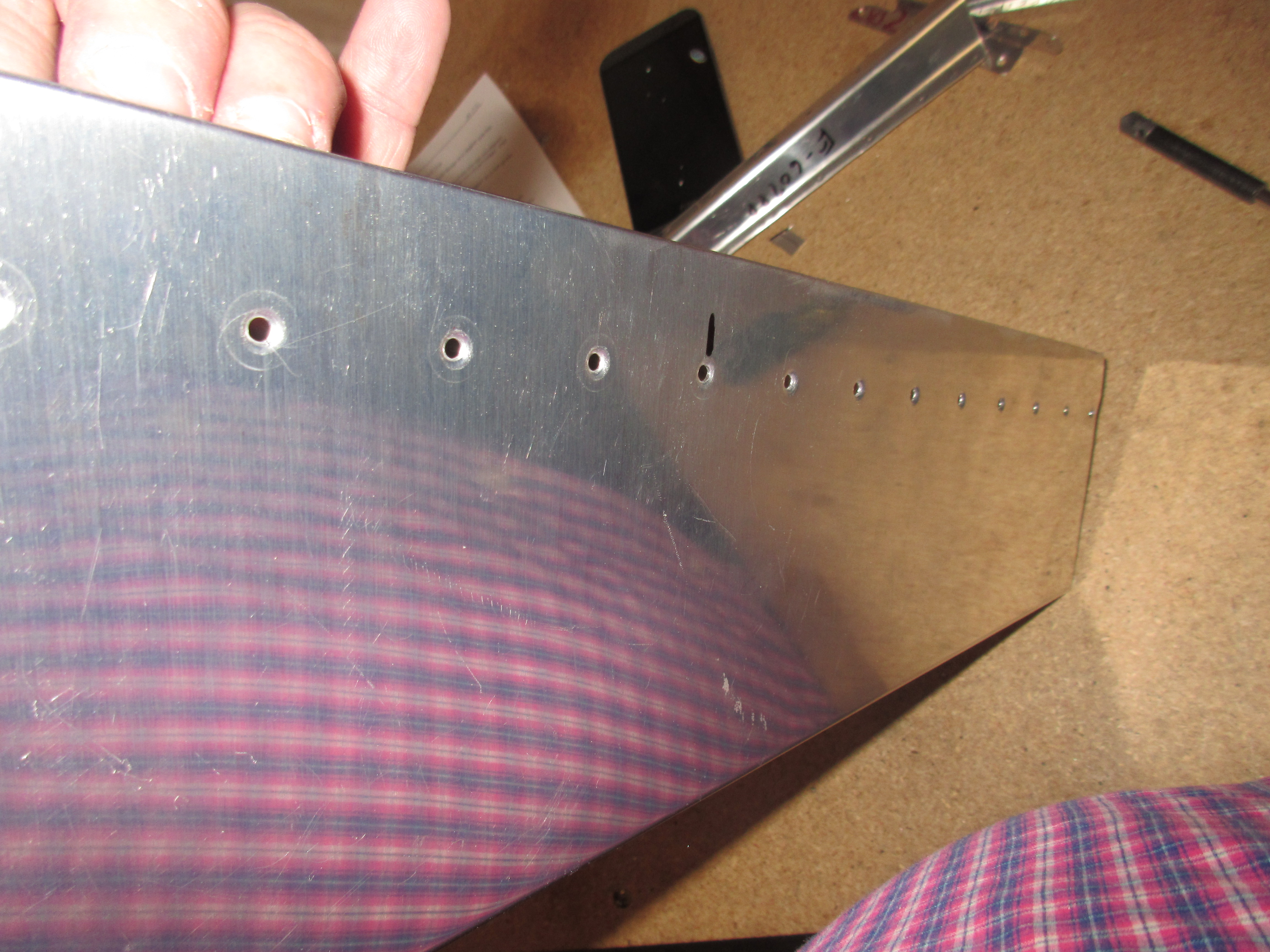
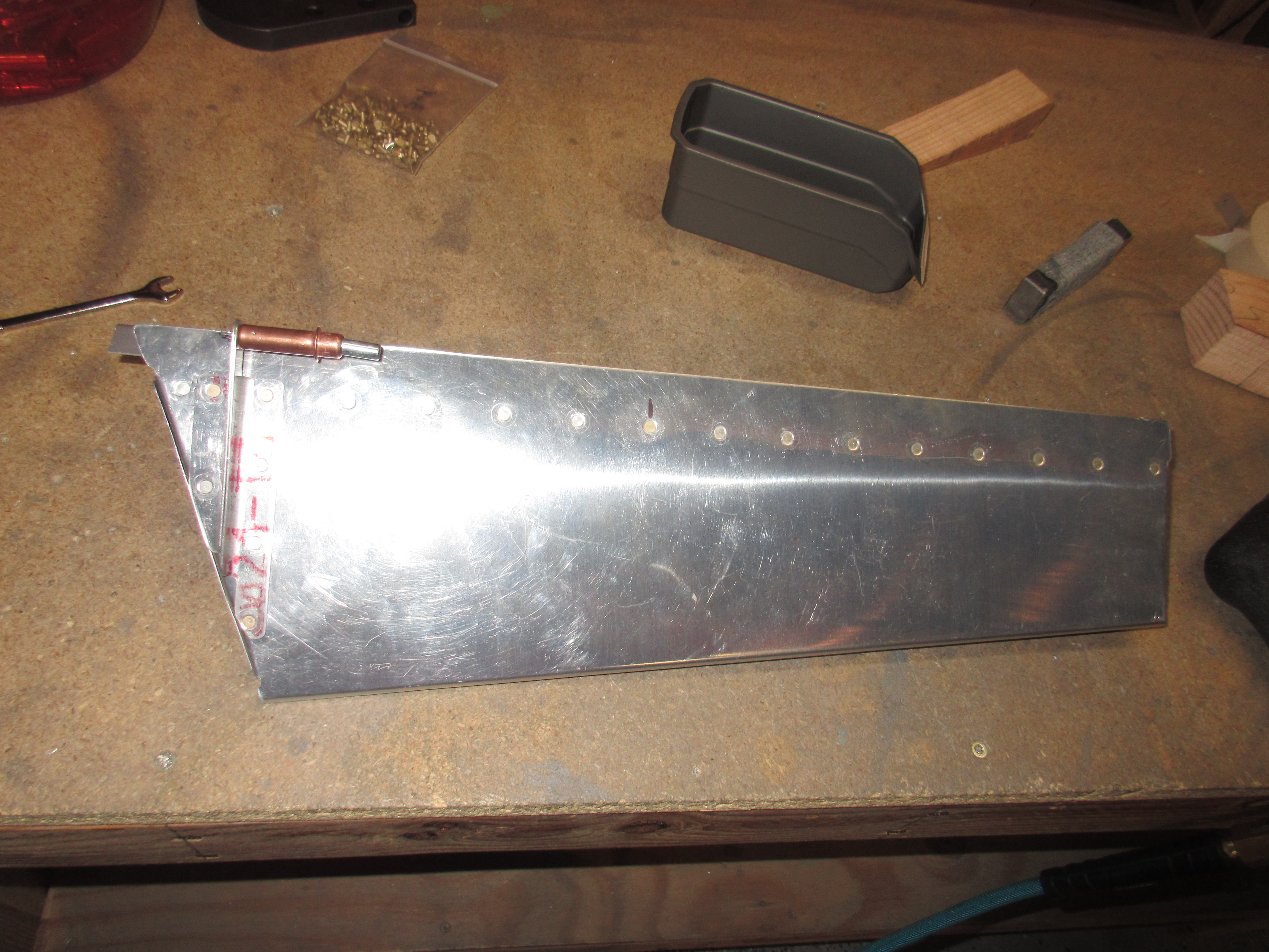
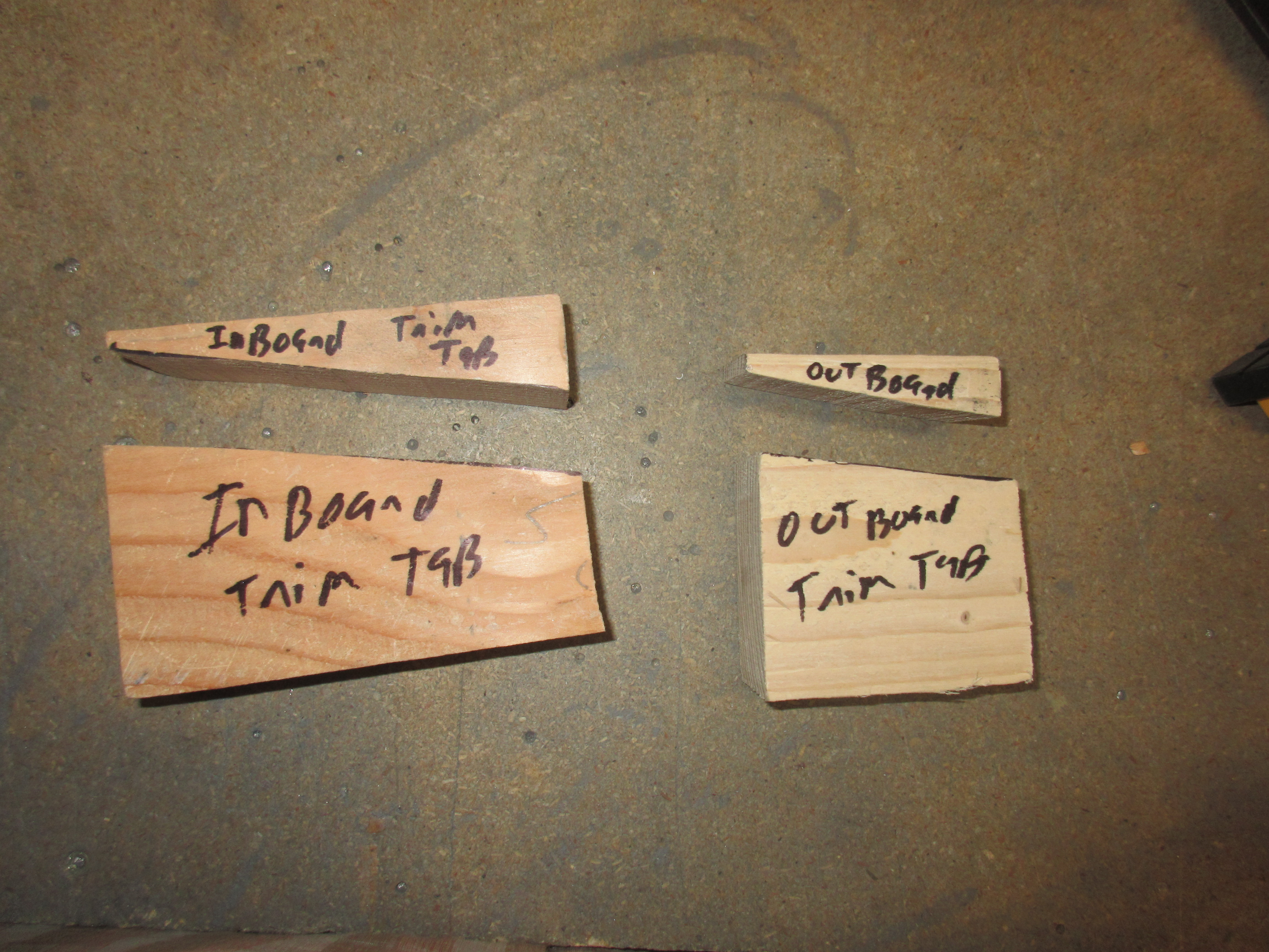
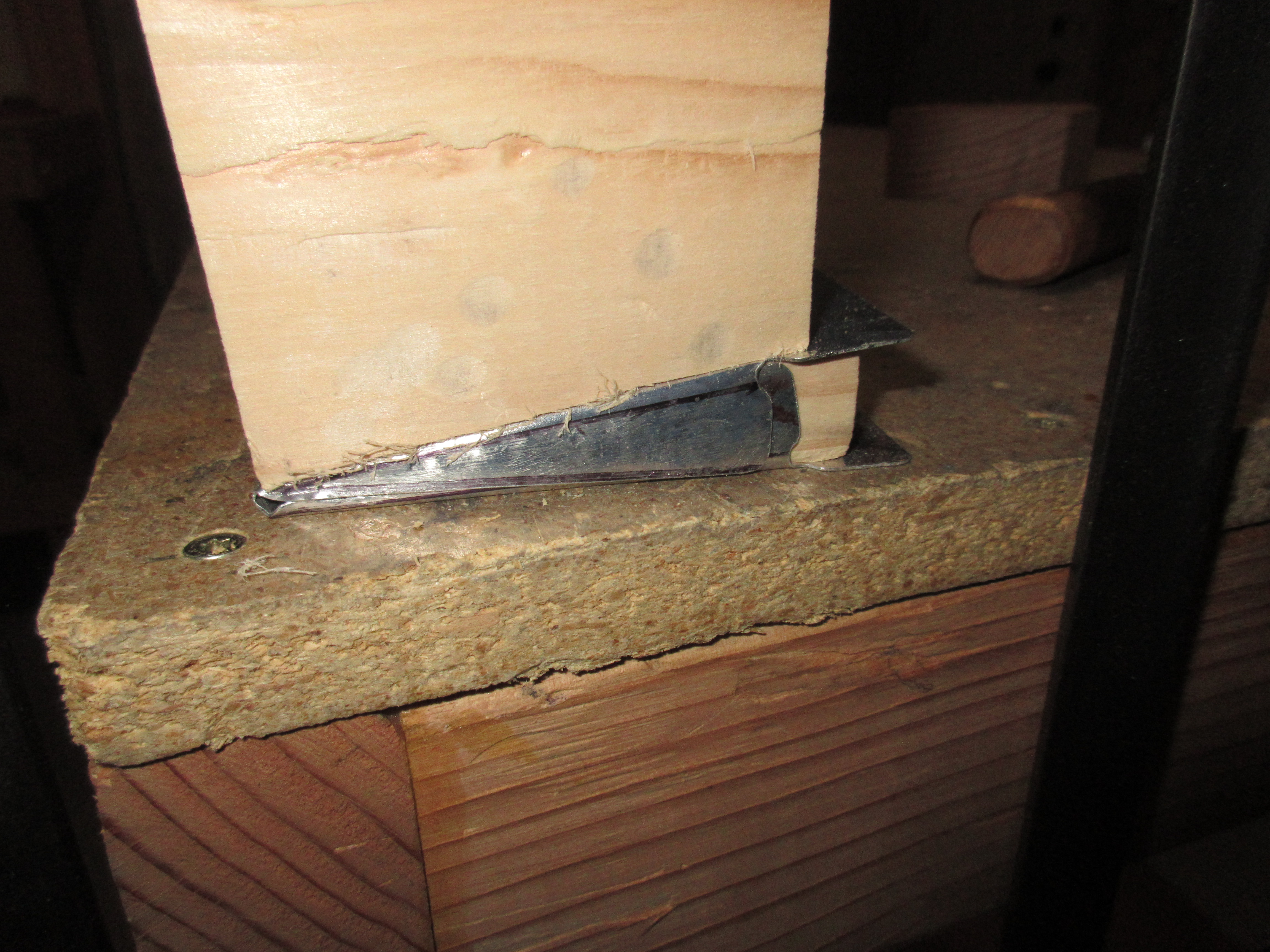
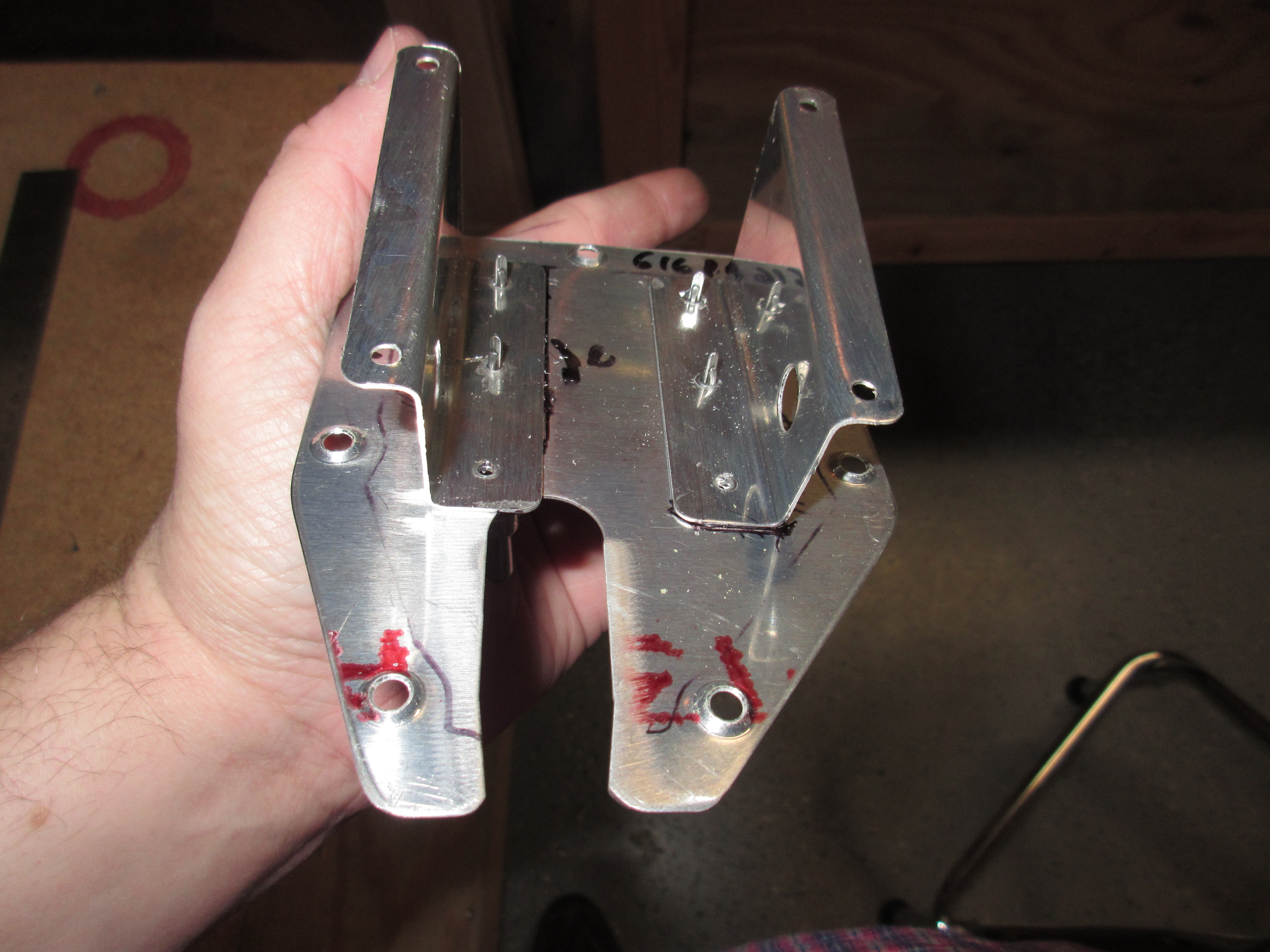
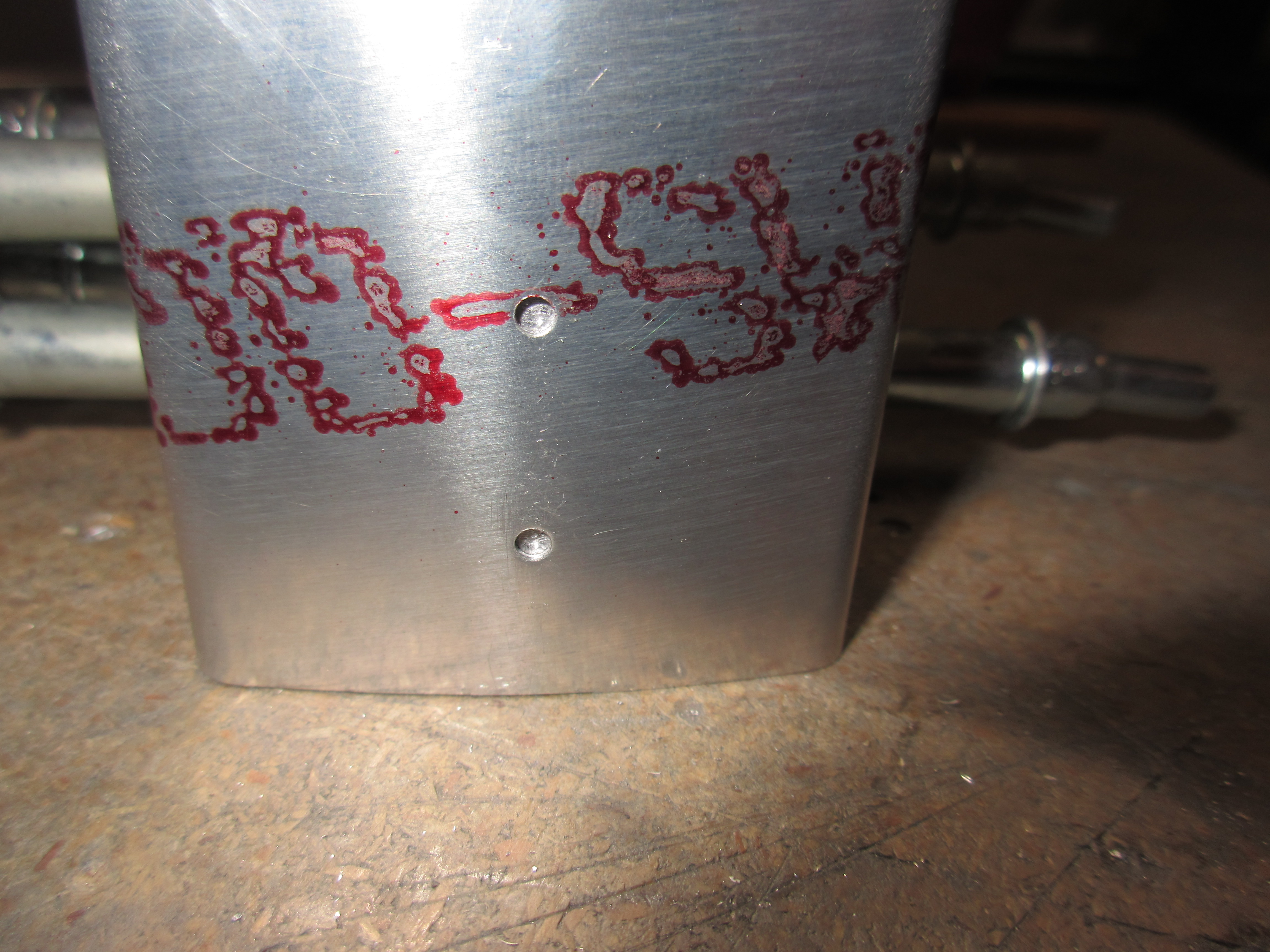
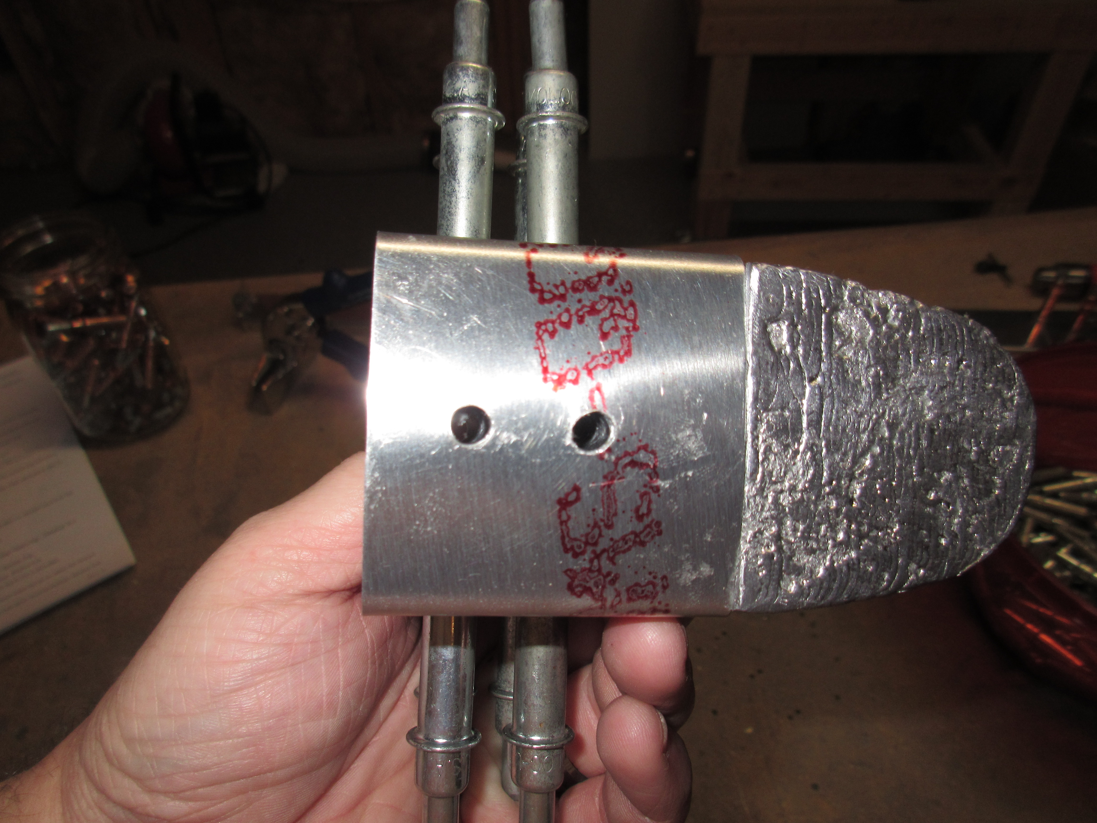
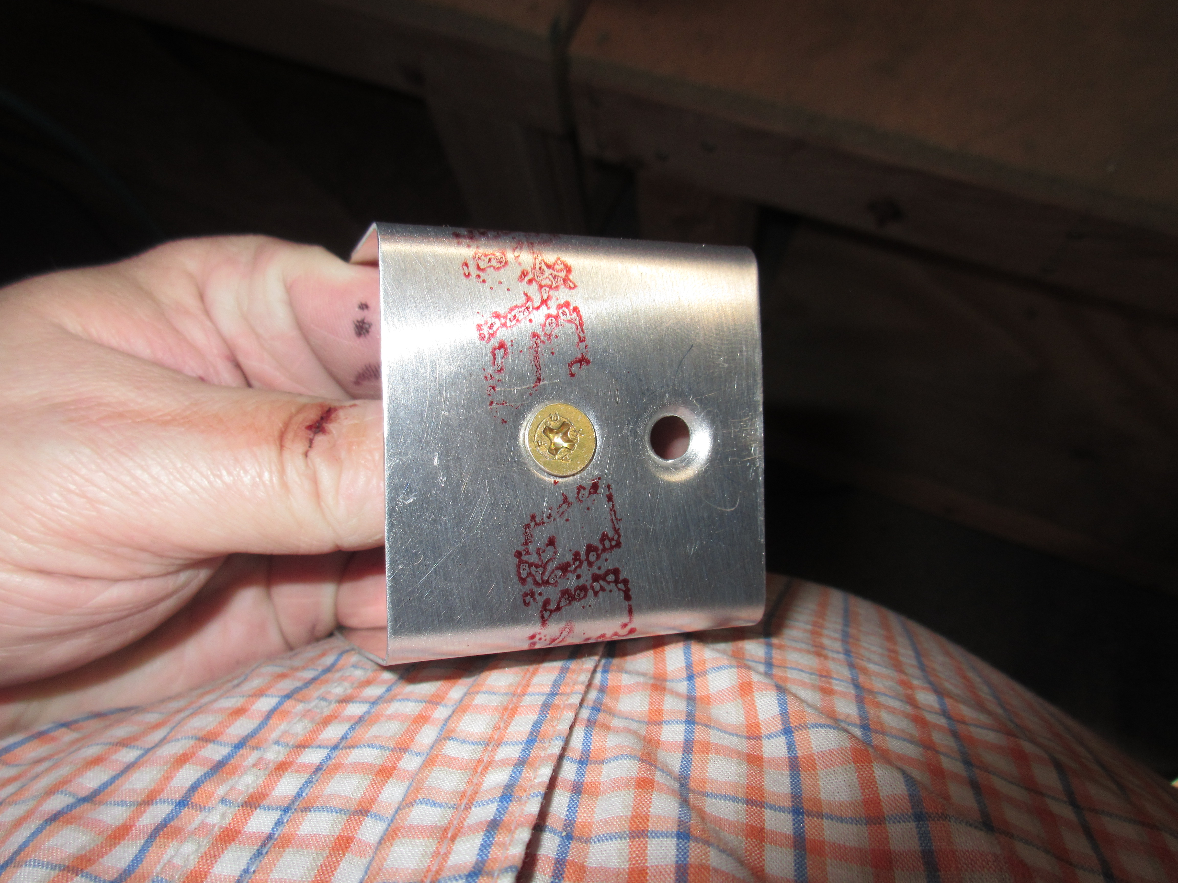
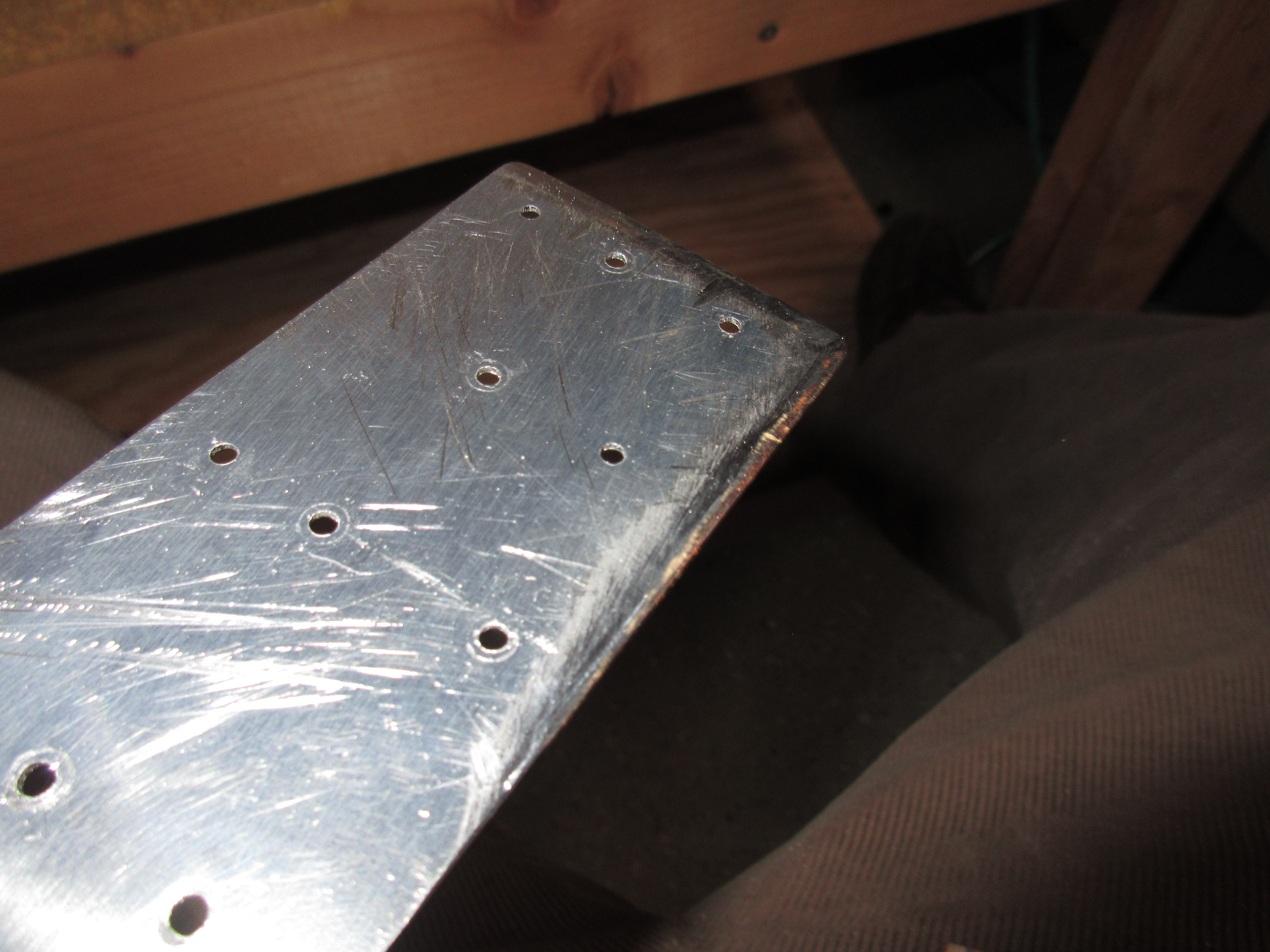
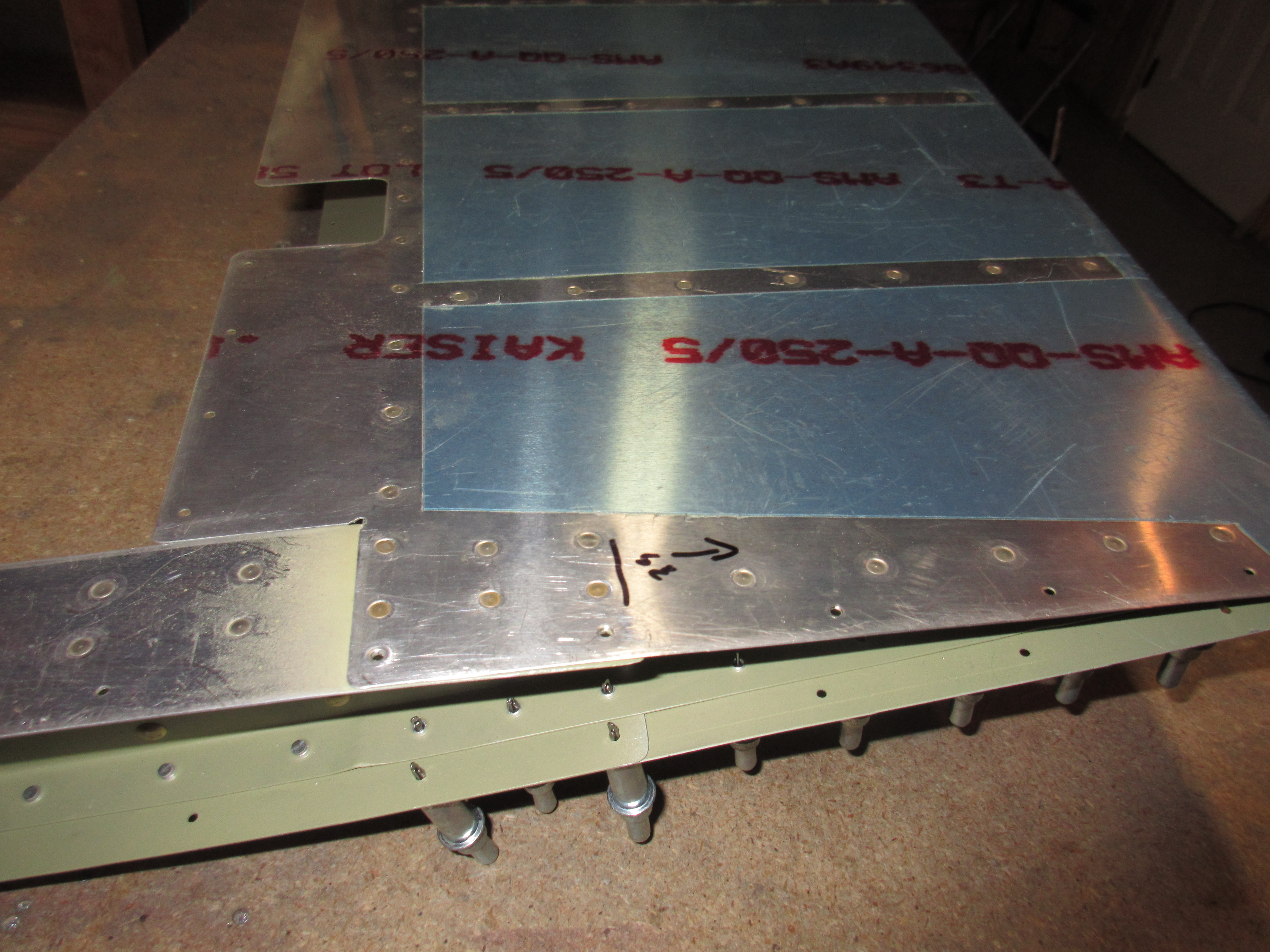
With that being done, all that remained was to mark and drill the holes on the tabs that I bent a few nights ago.  Van’s doesnt have these holes pre-punched, because its impossible to know where they’d end up after the bending, so we have to be creative.  Van’s does tell us to make sure the rivets from the trim tab do not interfere with the elevator skins, so I put the trim tab in its location, and marked where the pre-punched holes for it were on both the trim tab itself, as well as the elevator skin, seen in the photo above.  I then decided to place my elevator tab rivets between where the trim tab rivets go, so as to give me plenty of clearance.  I then drilled the holes with a #40 bit, followed by a #30 bit to fit the CS4-4 blind rivets.

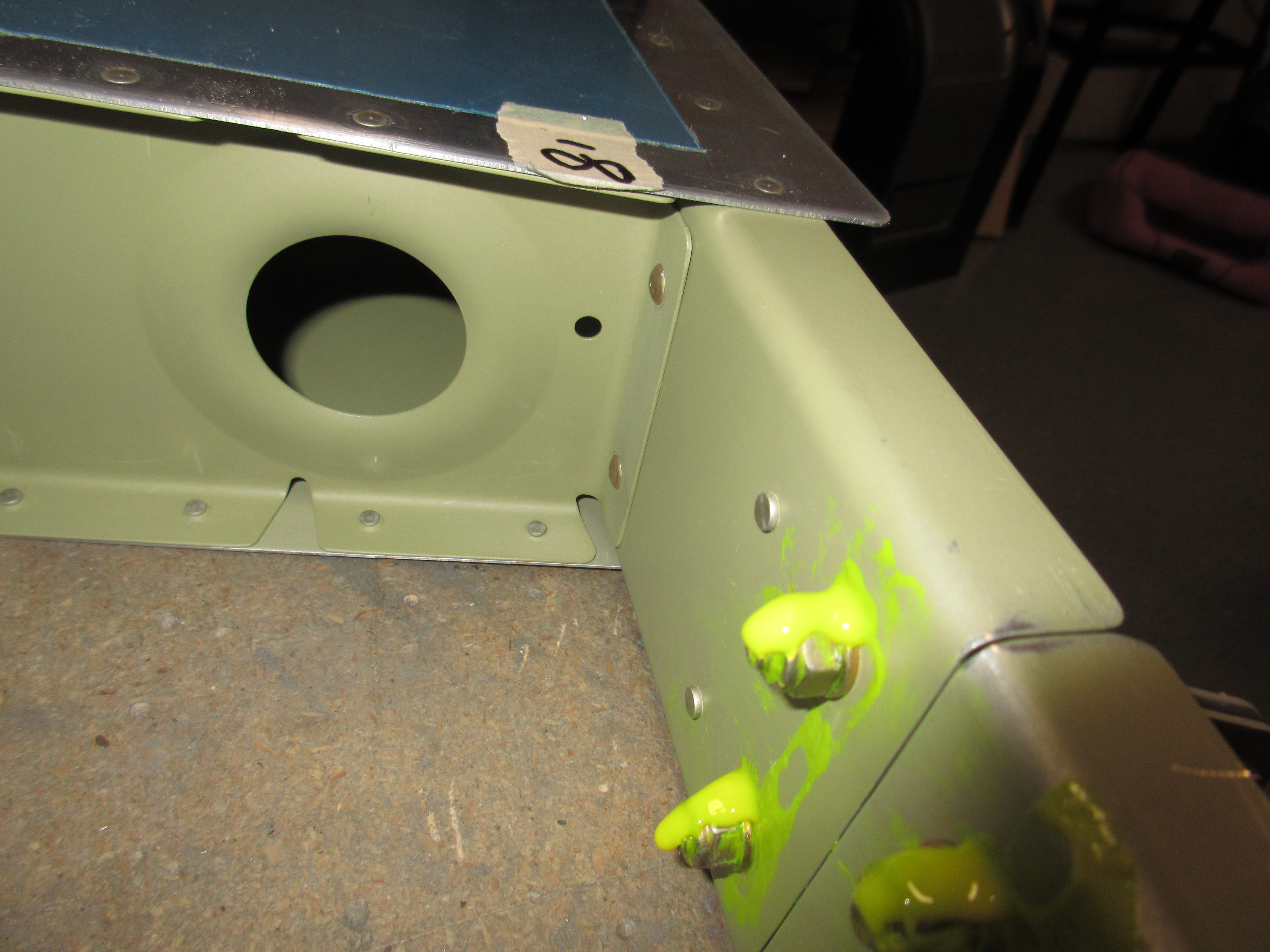
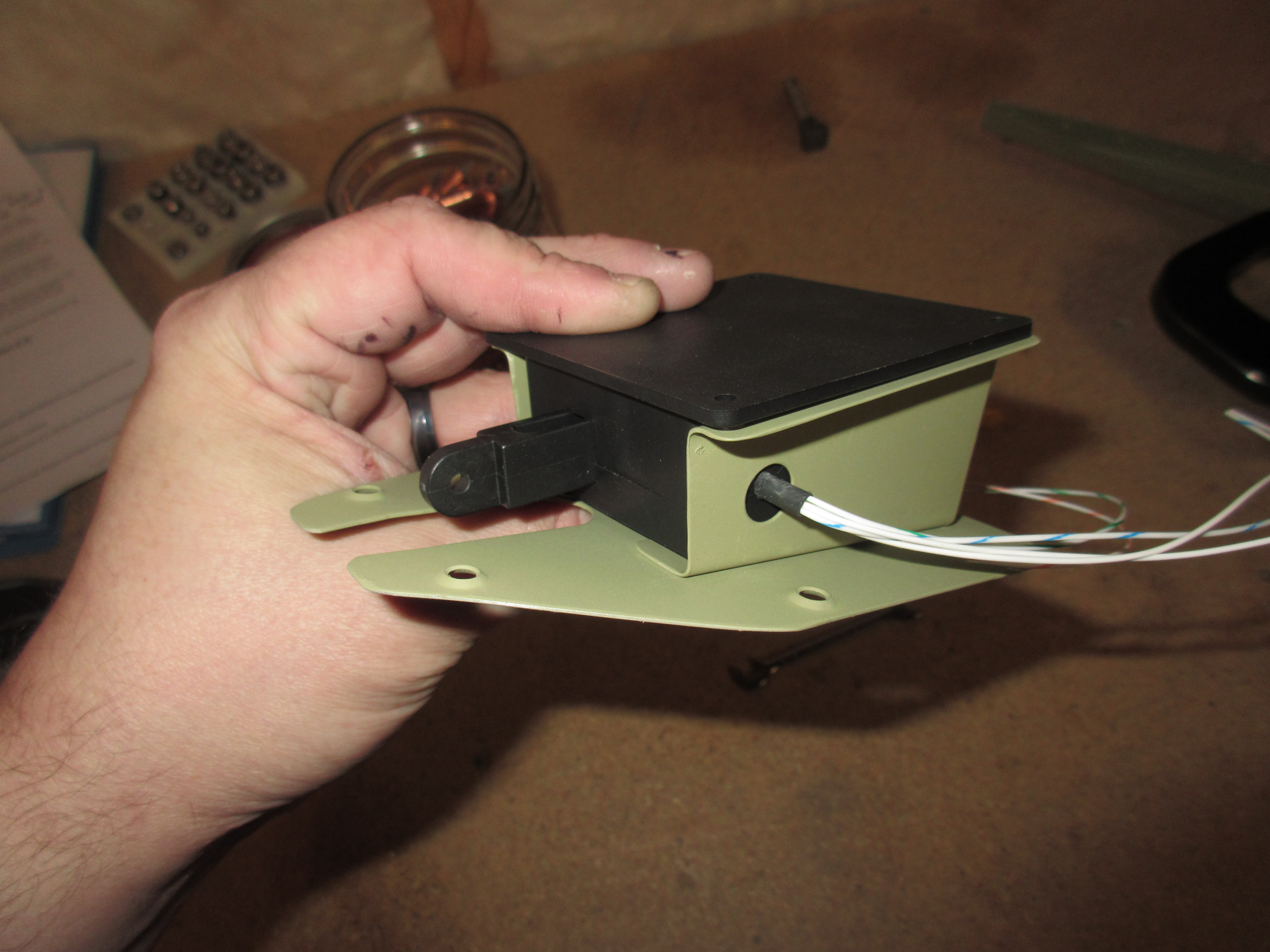
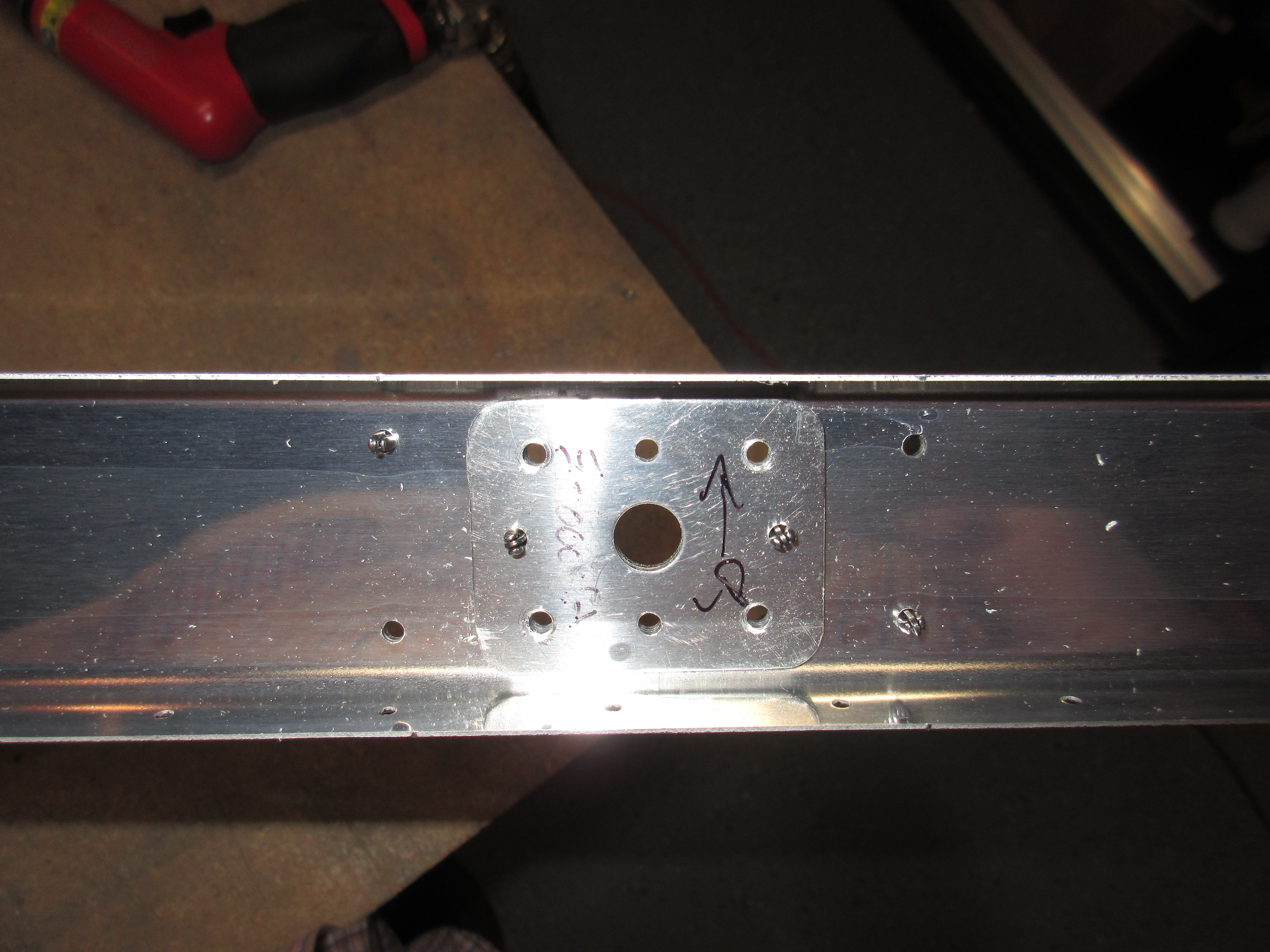
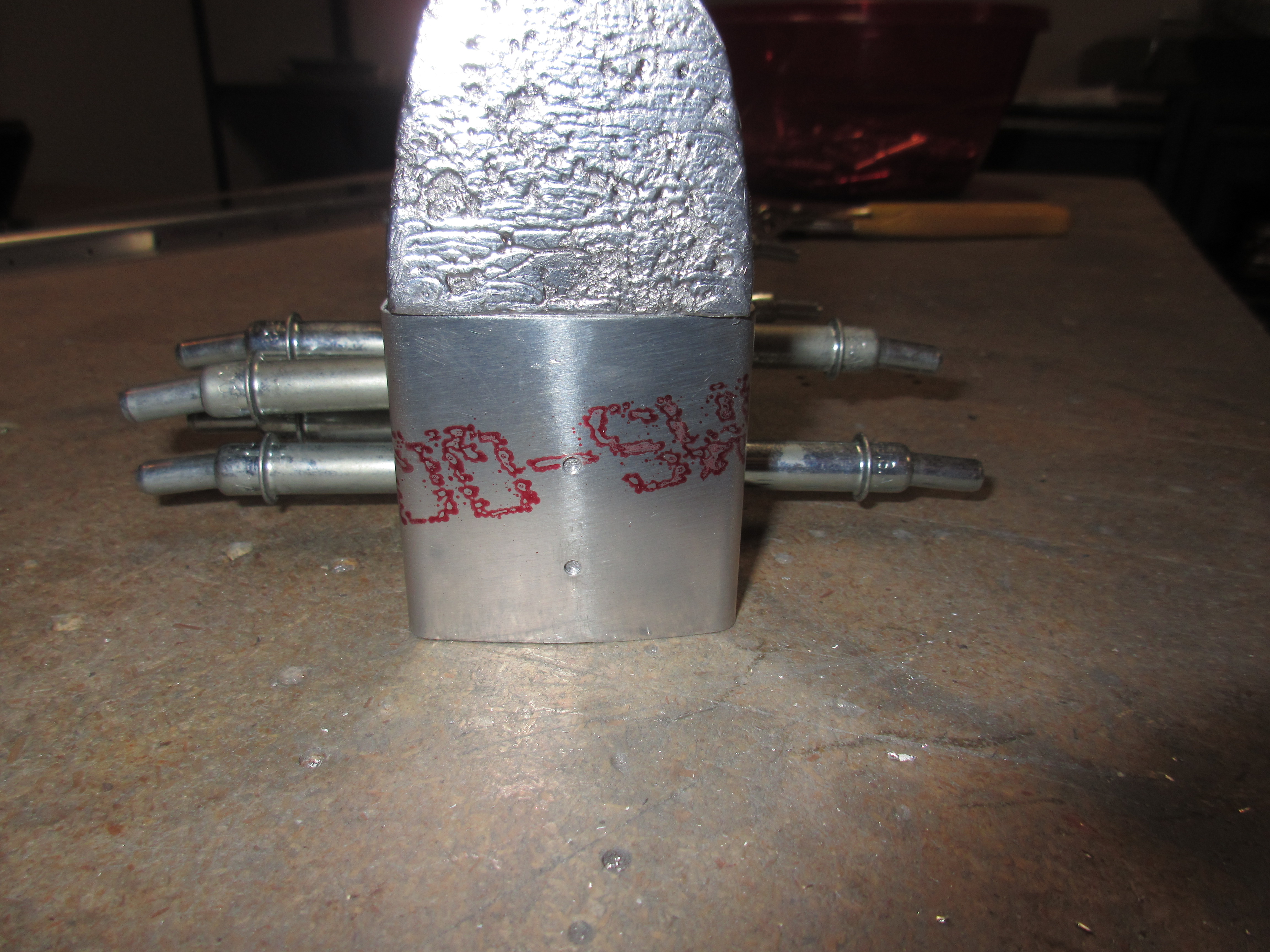
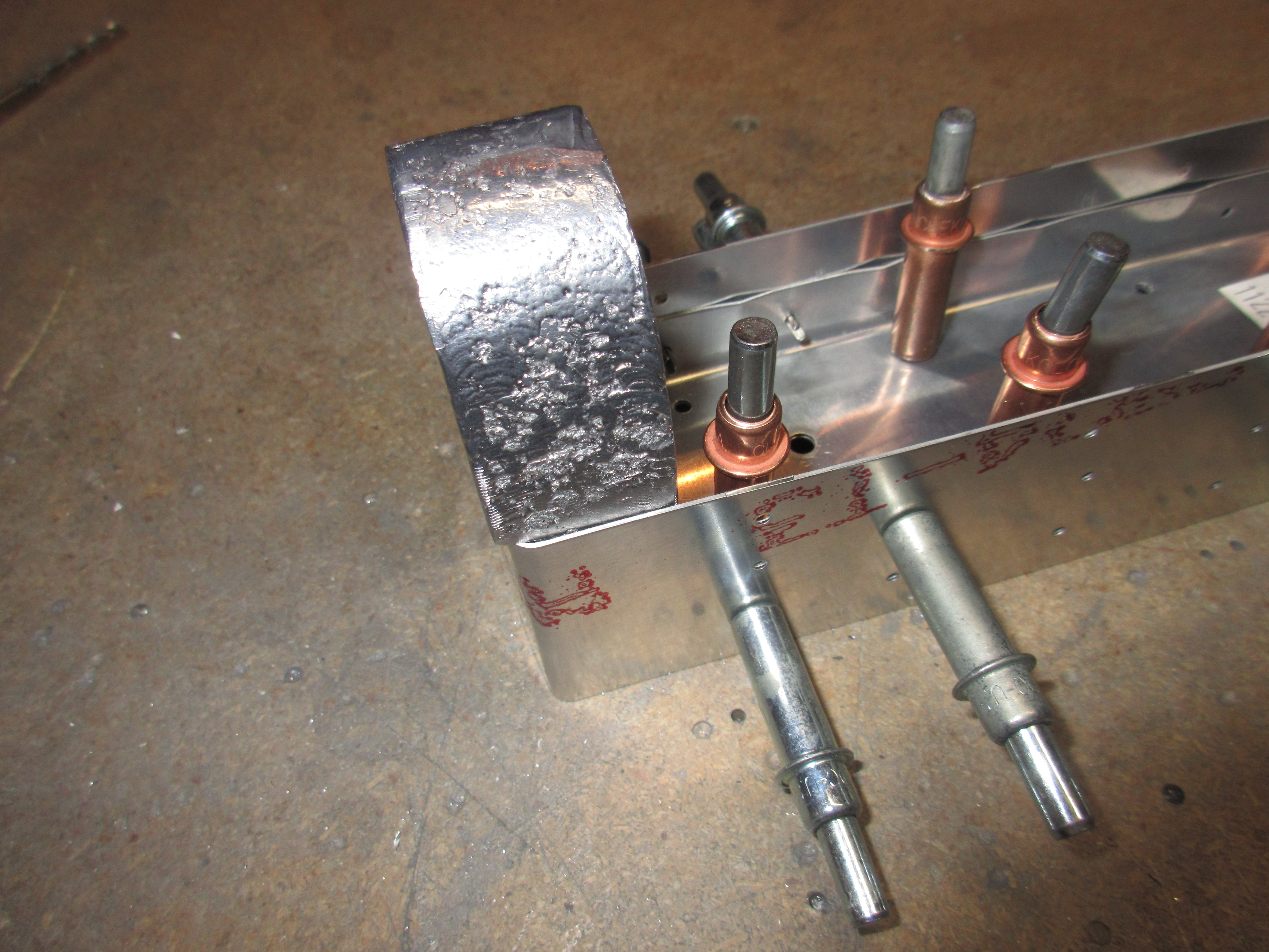
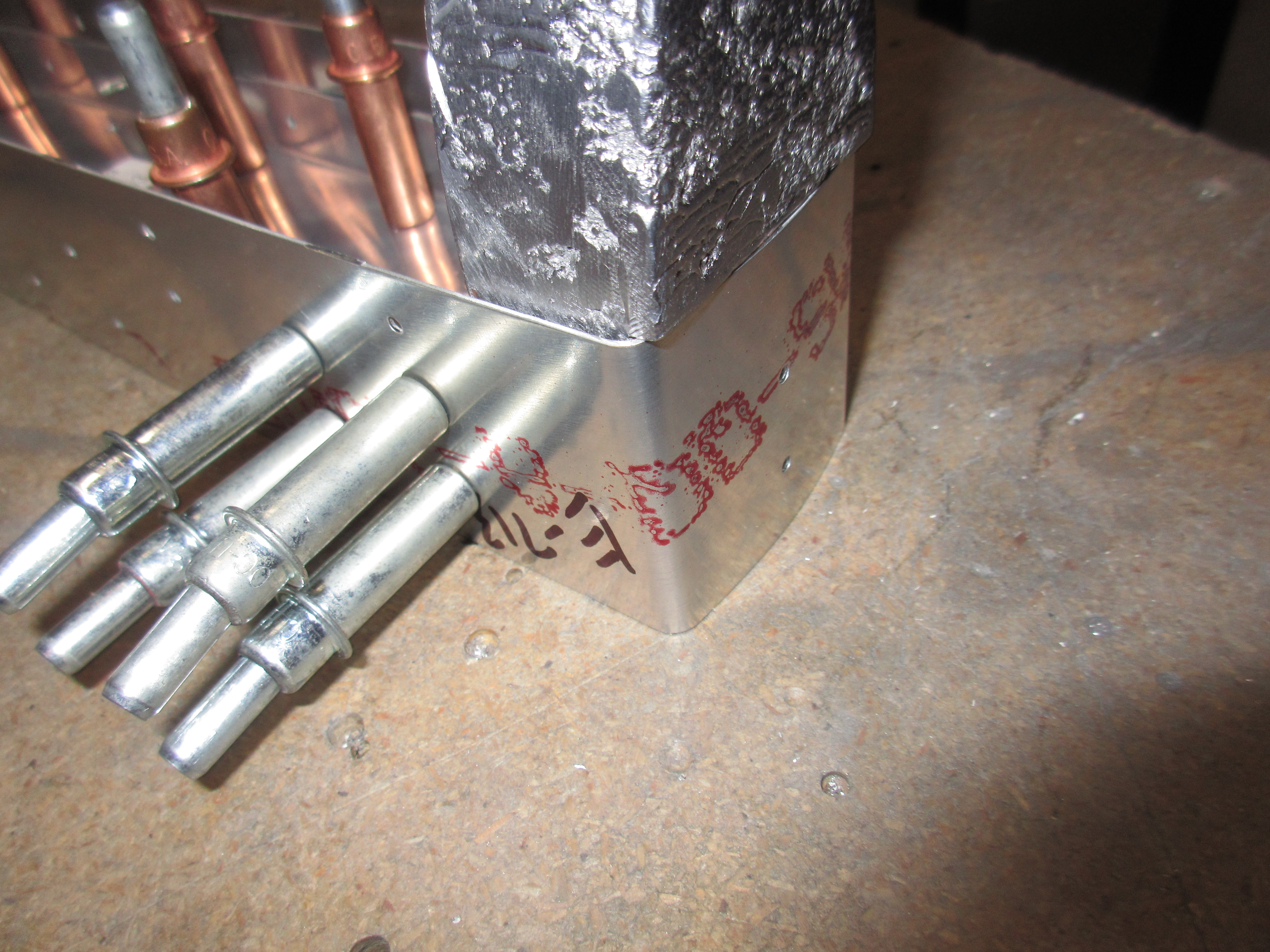
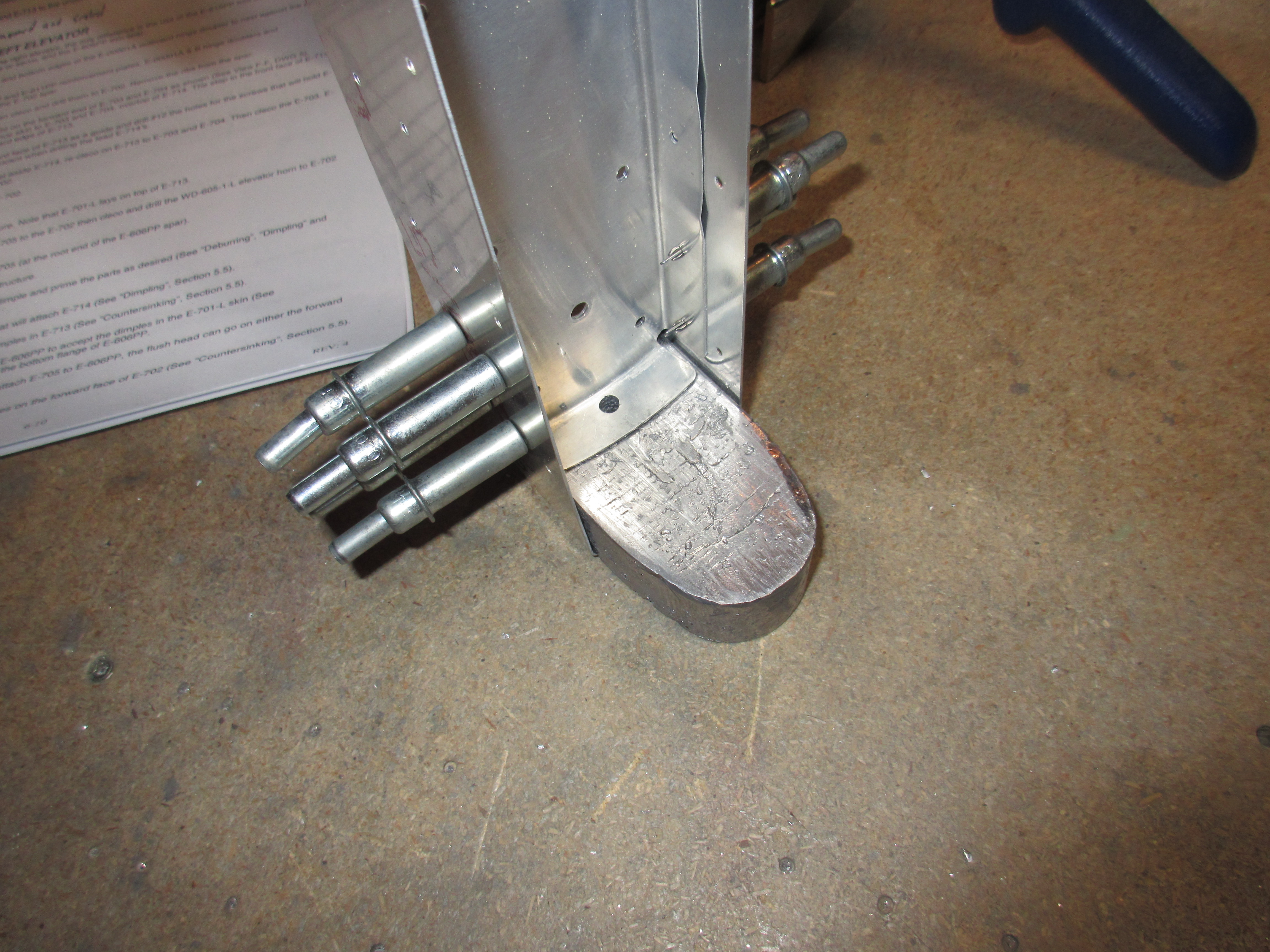
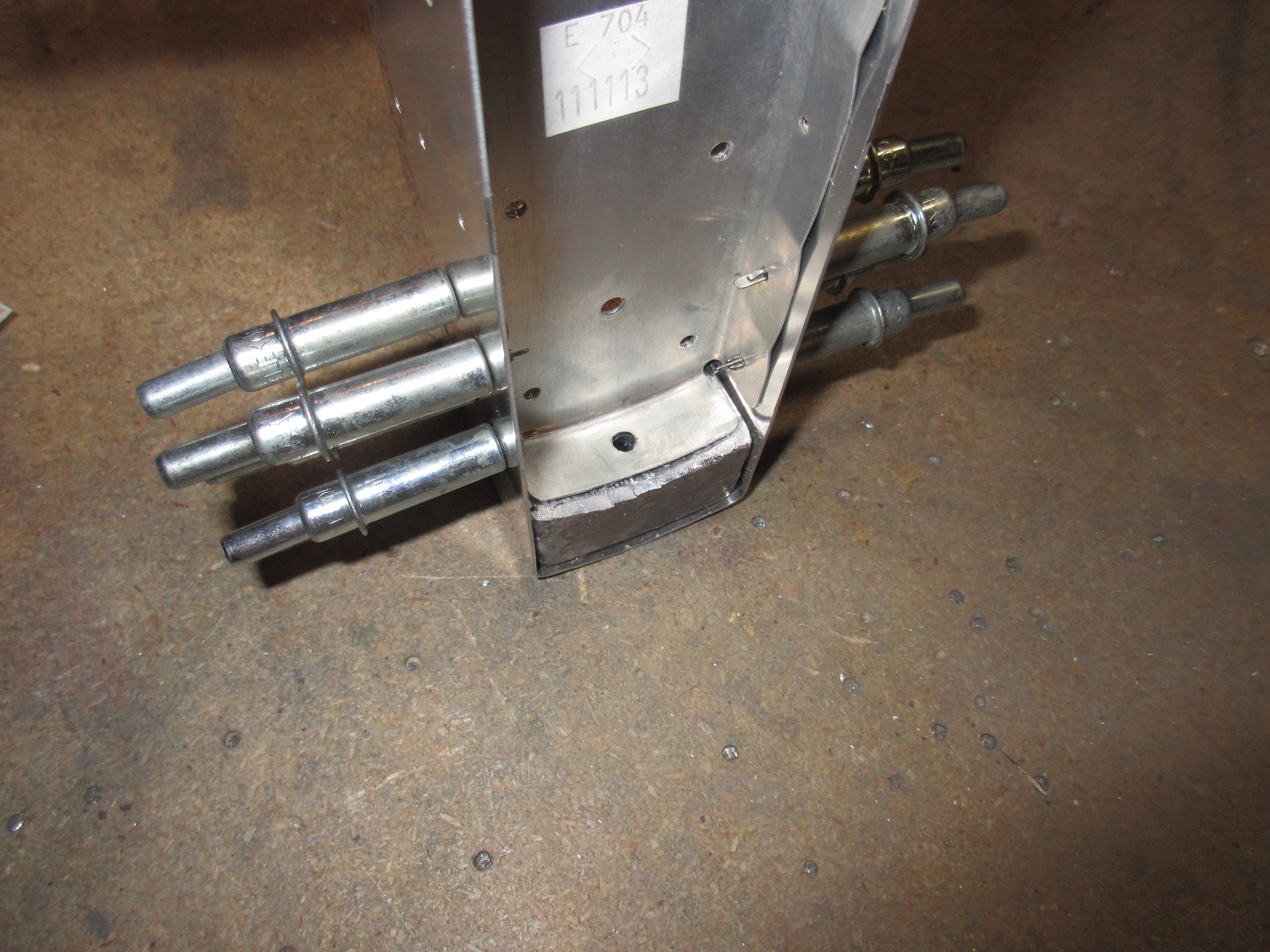
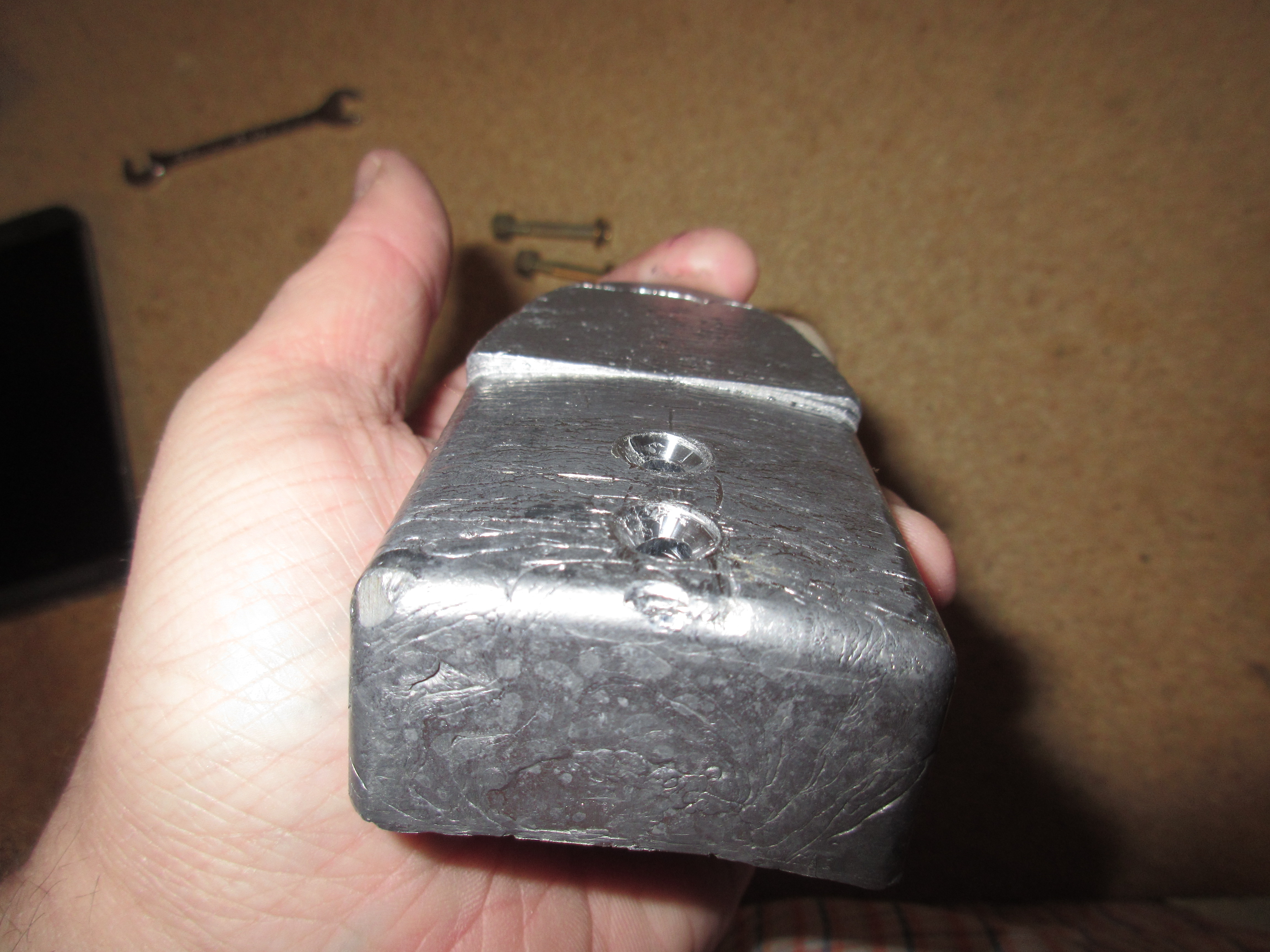
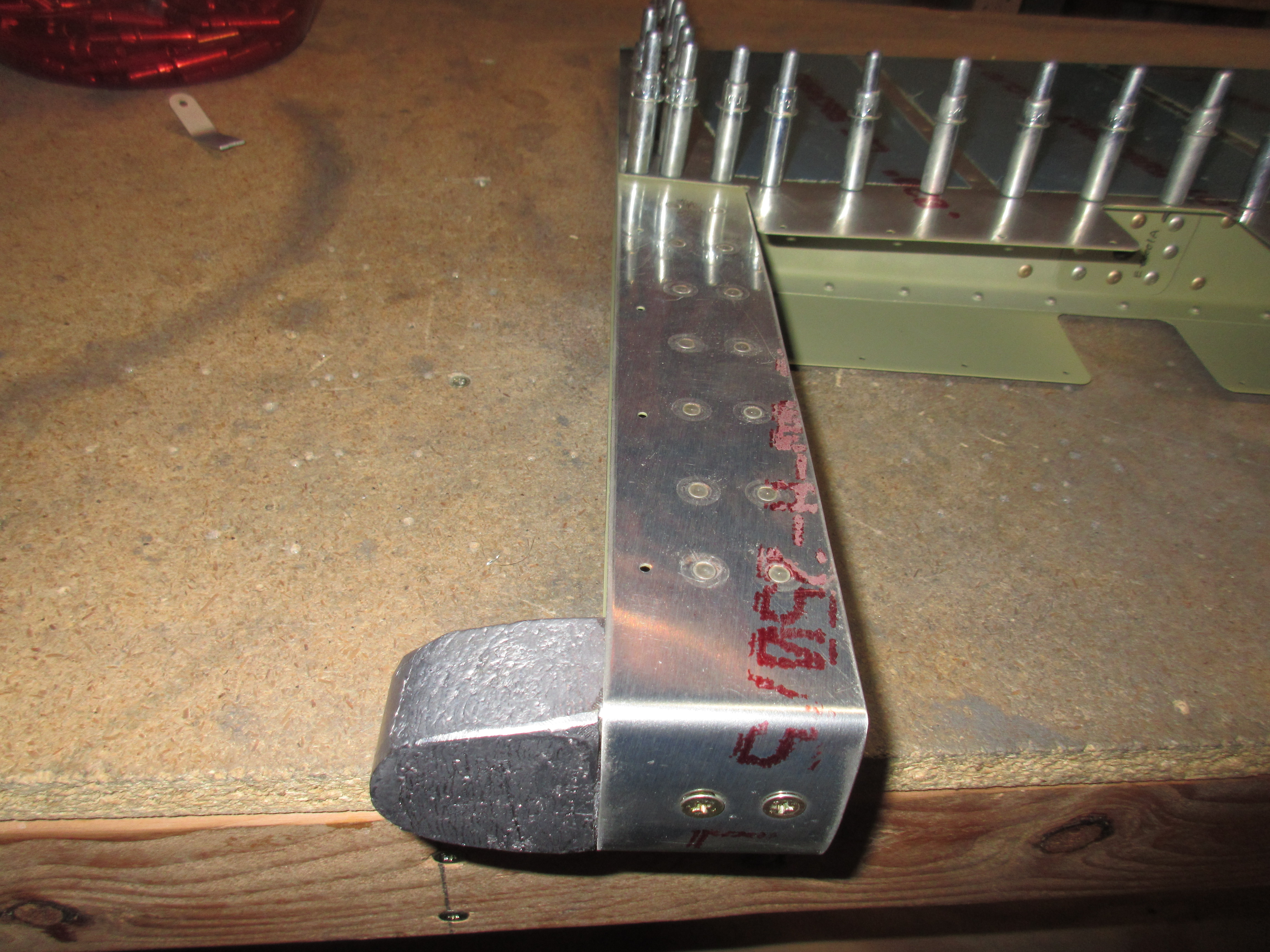
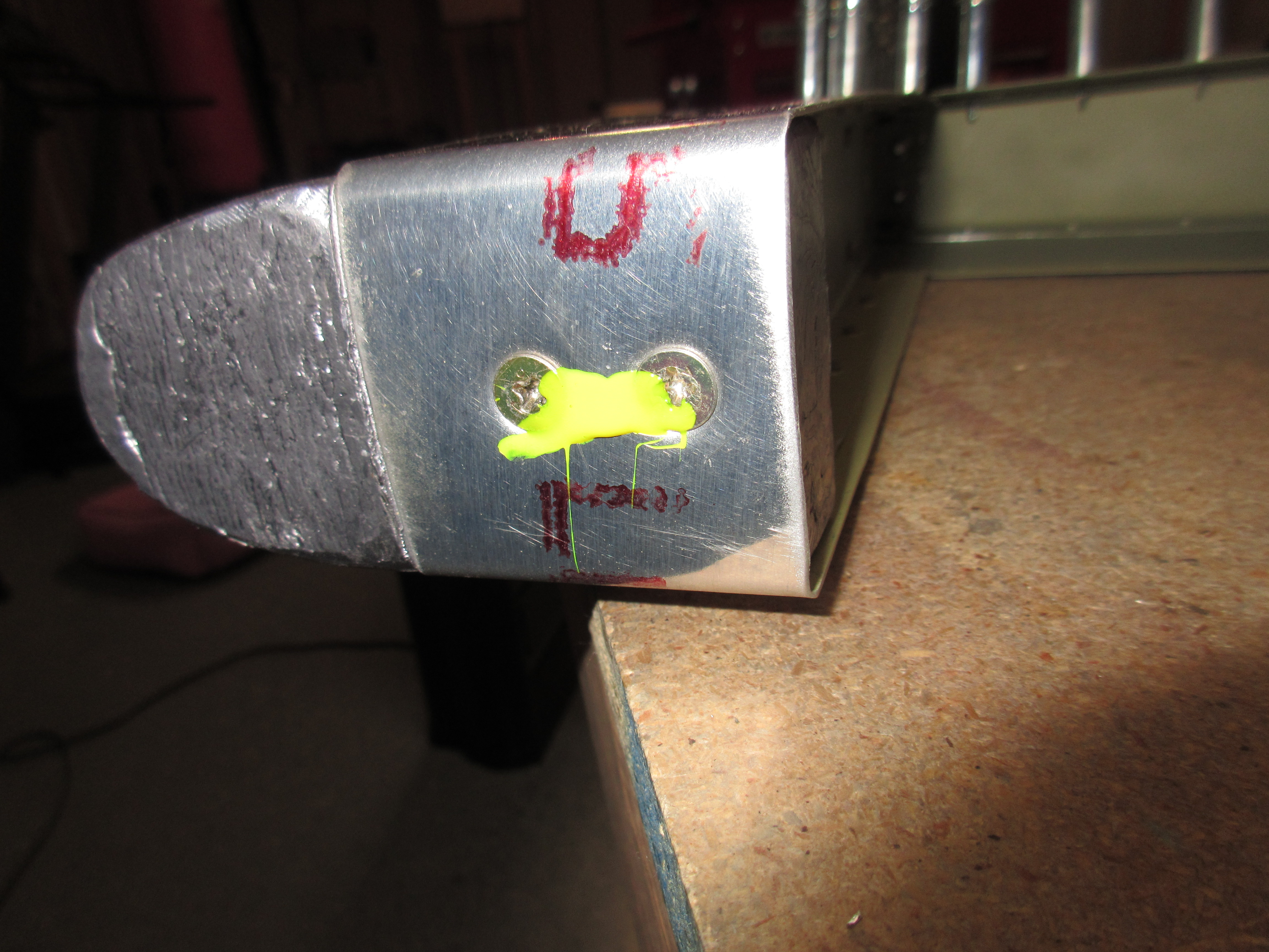
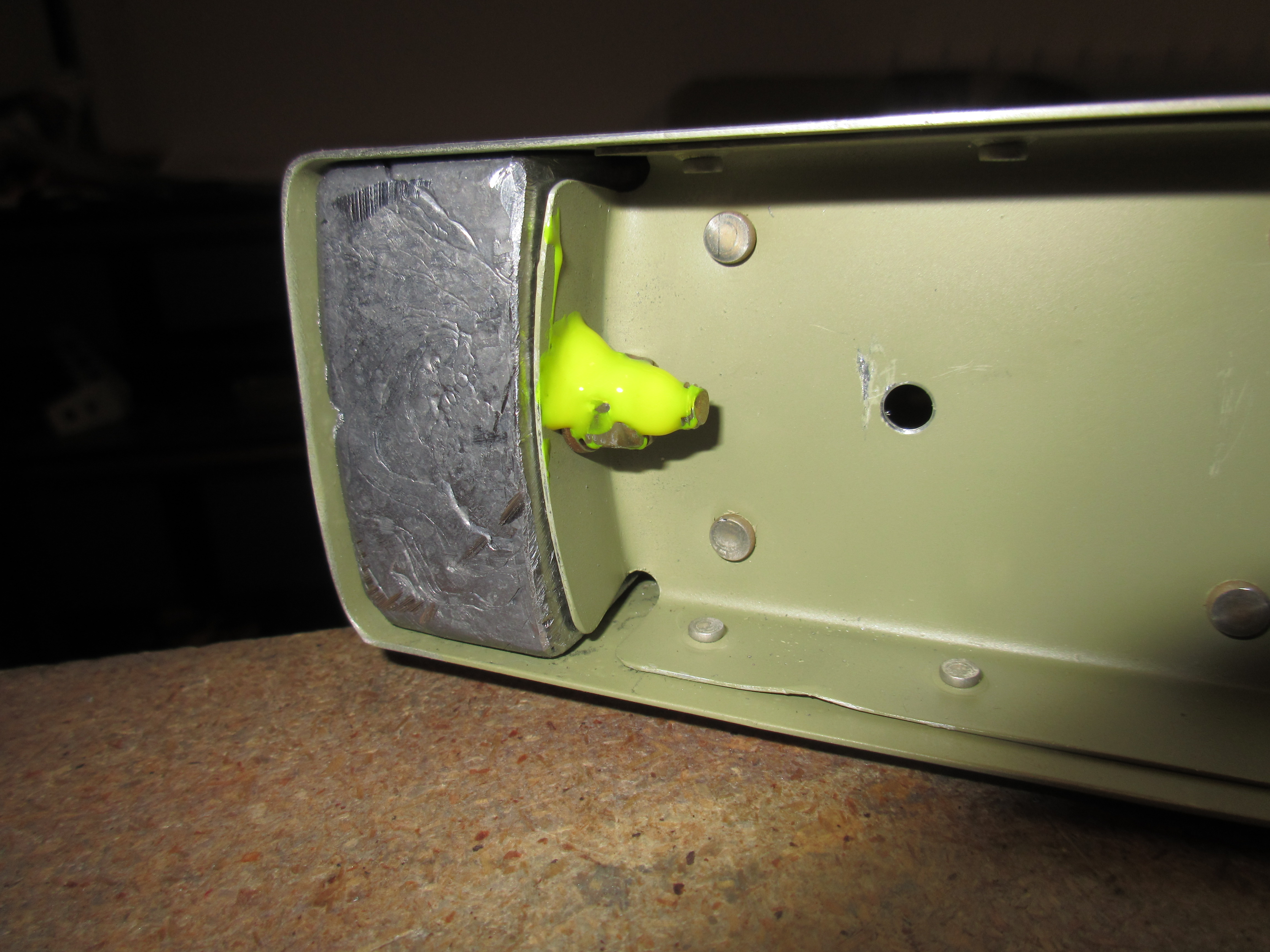
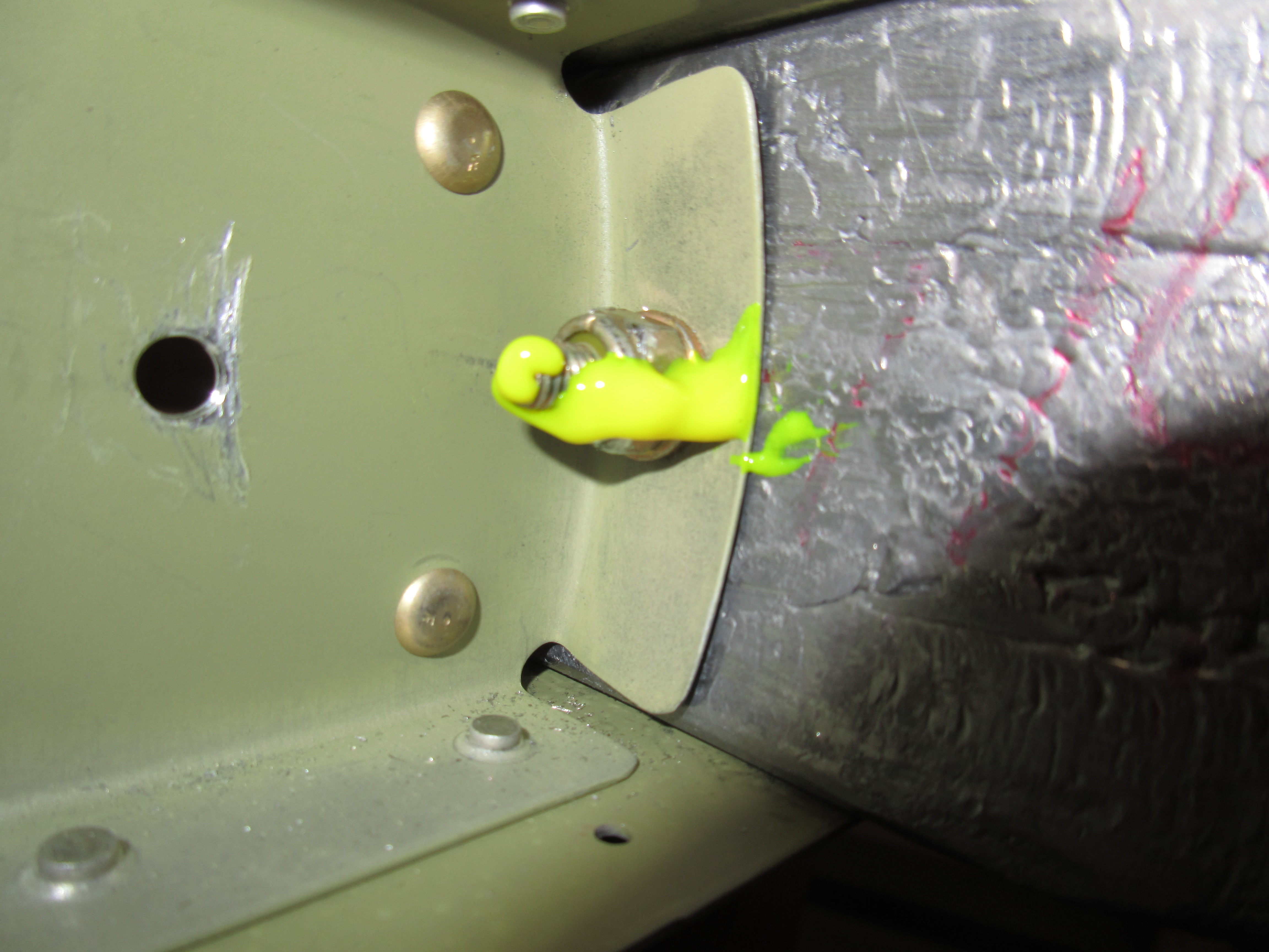
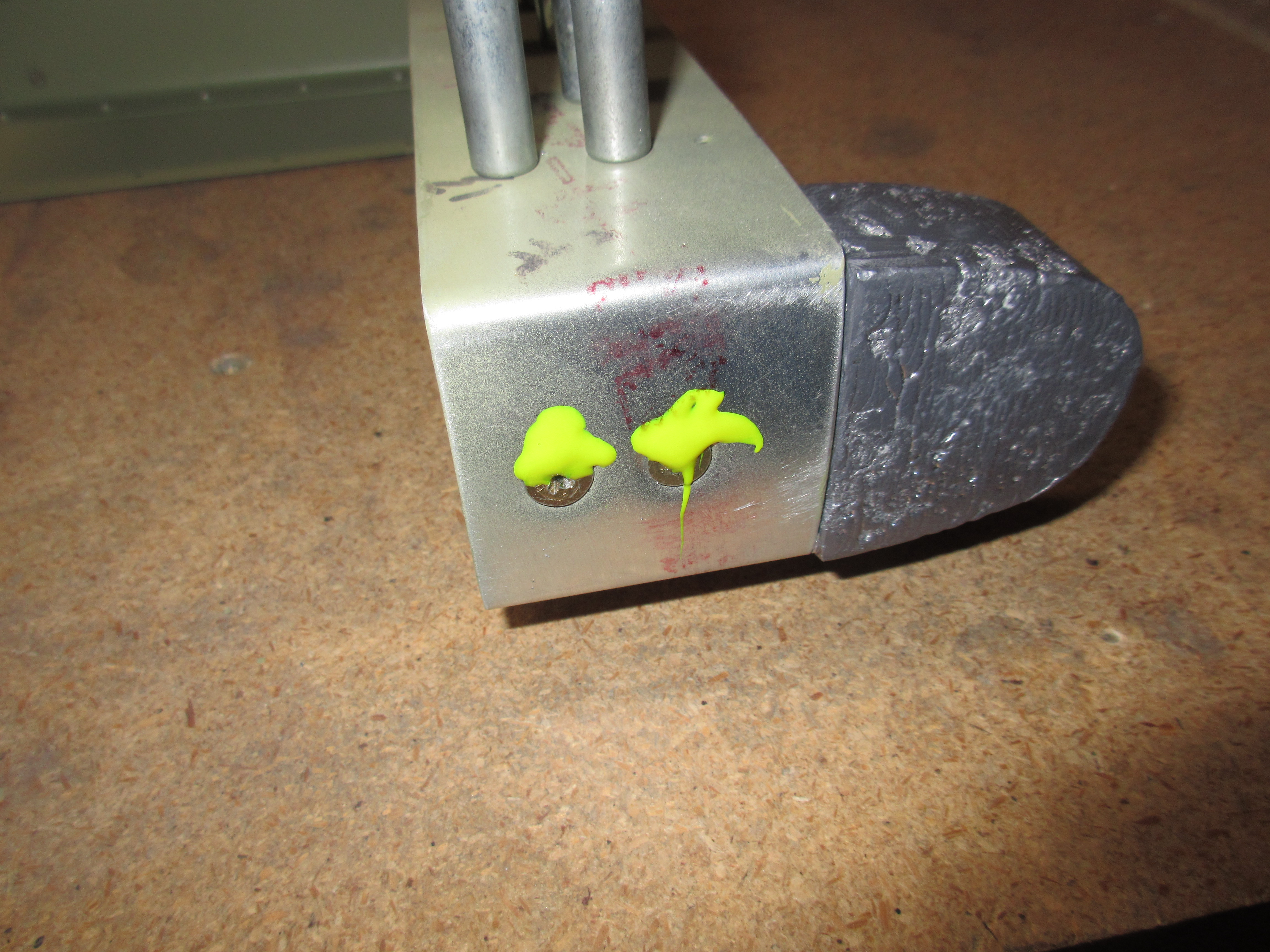
The last bit of work for the night was to bolt on the E-714 counterweight.  I picked our the screws, washers and nuts as called for by the plans, ran them through the counterweight assembly and then torqued them down to 30 inch/lbs of torque as specified in the manual.  Then, I gobbed on some torque-seal to make annual inspections easier in the future.

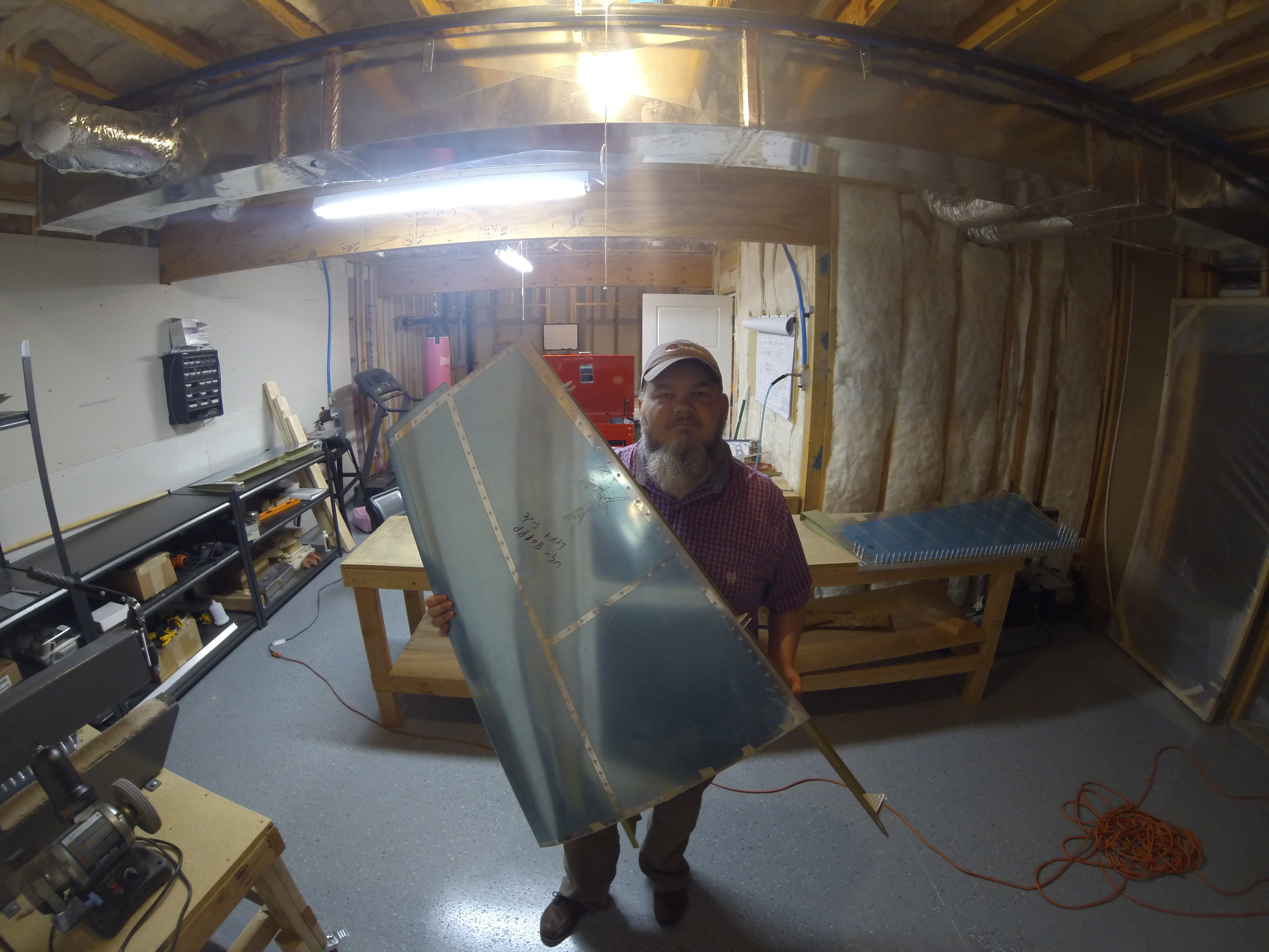
That finished up the work for tonight. Here’s a quick time lapse of the work to make the FAA happy that I actually completed the work, and a photo gallery of all the photos below that.


This slideshow requires JavaScript.

Google Photos Link: https://goo.gl/photos/B2SmEbJ6Q8Gg9iM29

Hours Worked: 3

Closing and Finishing the Vertical Stabilizer

After completing the horizontal stabilizer in a previous work session, I decided to continue on and finish the vertical stabilizer.  The Tech Counselor came out this morning and approved all my work so far, and that means its safe to close these guys up and mark them as done!  I started out by clecoing the rear spar back on to the vertical stabilizer skin, we had removed it this morning so the inspector could take a good look at the riveting done inside.

Once the VS-803PP rear spar was clecod on, I inserted an AN426AD3-3.5 rivet into every other hole and used the squeezer to set the rivets. Once they were all done on both sides, I removed the clecos and then riveted those holes. Since I was able to use my squeezer, these rivets came out perfect:

Next up was to attach the VS-707 rib to the VS-803PP rear spar assembly using LP4-3 blind rivets.  These were easily done using the pop rivet tool, making sure to keep them flush with the parts when setting.

Finally, the last step was to rivet on the VS-704 end rib to the VS-803PP rear spar assembly using AN470AD4-6 rivets and then attaching the VS-706 tip rib to the rear spar using AN470AD4-4 rivets.  I used the squeezer on these guys, and they set really nicely. Its still very nice to see just how rigid everything ends up being once it all riveted together. These skins are nice and tight and have zero oil canning.

Here is a nice time lapse video I took of this session:

Of course, the obligatory happy selfie of the finished vertical stabilizer:

And here is all of the photos I took of tonights build:

  • IMG_1347
    IMG_1347
  • IMG_1346
    IMG_1346
  • IMG_1345
    IMG_1345
  • IMG_1344
    IMG_1344
  • IMG_1343
    IMG_1343
  • IMG_1342
    IMG_1342
  • IMG_1341
    IMG_1341
  • IMG_1340
    IMG_1340
  • IMG_1339
    IMG_1339
  • IMG_1328
    IMG_1328
  • G0030929
    G0030929

Google photos Link: https://goo.gl/photos/SX4DAd6o8eWHGtPu7

Hours Worked: 1

Closing and Finishing the Horizontal Stabilizer

Since I have had my horizontal stabilizer inspected and approved, I am ready to close it up and finish it! I started tonights session by re-clecoing the front spar onto the horizontal stabilizer.  I had removed it so the inspector could get a good look inside and check my work.  Once I had it all clecoed on, I double checked the orientation to make sure it was all correct.

Once it was all clecoed into place, the rest was pretty easy! I dropped in AN4263-3.5 rivets and squeezed them with my pneumatic squeezer.  I skipped every other hole with clecos, so once I had the unclecod holes rivets squeezed, I went back and removed the clecos and riveted them.  Squeezing makes a very nice rivet and everything came out looking very nice.

Once the rivets were set along the spar and skin, there were a few that we had to get to on the ends that attached the HS-706 tip rib to the HS-603PP rear spar. Those are using AN470 rivets, but I was still able to get them with the squeezer.

Then, there are 4 blind rivets that we have to set using a pop-rivet tool.  These are what attach the HS-603PP rear spar to the HS-708 main rib, and we have to use BSPQ-5-4 blind rivets in these holes.  These are some pretty beefy blind rivets, and it took a good bit of force on the pop rivet tool to get them set, but they came out looking great.

Finally, there are a few more AN470 universal head rivets that attach the HS-00005 inboard aft rib to the HS-603PP rear spar, but I was able to use a squeezer to set these.  They are fairly long -7 rivets due to all the metal they tie together.

I did also cover my bolts with some torque seal, and made a hell of a mess with it!  As you can see in the photos, this stuff is like Pro-Seal, and gets everywhere!  I tried to clean it up the best I could and made sure the bolts were covered to make inspections easier.  That was it for closing up the horizontal stabilizer!  One of the suggestions that the Tech Counselor made was to make sure I included plenty of photos of me doing the work, which is a bit difficult given that I am building this plane all alone.  I decided to use my old Go Pro and do some timelapse videos.  I will include them in future posts.  Here is the obligatory selfie of me holding the finished stabilizer!

And here is the time lapse video of the construction.  I set the Go Pro to do a photo every 10 seconds, I may do it at 5 seconds on the next video.  Let me know what you think.


Link to Google Photos:  https://goo.gl/photos/RABUeY3Z4gXmMA9U9

Hours Worked: 1.75

Riveting the Left Elevator

The primer has dried and cured on my left elevator parts, so theres only one thing left to do… Start assembly and riveting! I started out the session by bending the tabs on the elevator skin.  On this left skin, there are two tiny little tabs that must be folded over, just like the trim tab, in order to close the edge where the trim tab sits.  These also support the outboard edge of the skin, much like a rib would.  This is a very delicate operation, and one that can go wrong quickly.  When I bent the trim tab, I had a second one for a spare so I didn’t worry.  With this skin, I only have the one, and I have a ton of work in it already! I used the same bending blocks as I did for my trim tab, since the angles are pretty much identical.  I inserted the block and clamped it down to the bench.  I used a straight edge held against the block of wood to make sure I had it right on my bend line.

We bend the bottom tab first, and then fold the top tab over the top this way we form a lip that allows water to run over the skin, and not get trapped between the tabs, or worse, get inside the skin! Notice my note to myself (1 st!) so I don’t bend the wrong tab first.  I used a large block of wood and a small hammer with light taps to bend the bottom tab into position.  Once I had the bottom tab where I liked it, I did the same with the top tab, and the end results were decent.  While they are not perfect, and have a few tiny dents from the bending, I am happy with them as they are.  The dents wont be visible since they are on the inside of the edge and will have the trim tab butted up against them.

Next up, I  dimpled all the parts and skin.  I like to dimple after priming because it makes scuffing in preparation for priming so much easier.  I dimpled the skin, spar, end ribs and all associated parts for the left elevator.  I used a combination of my squeezer and the DRDT-2.  I had to use my squeezer on the skin this time, due to how tight the trailing edge is.  Once I had all my parts dimpled, I continued on with the rest of the plans.  In the section titled “Riveting the Left Elevator”, Van’s has us start out by riveting E-704 End Rib and E-703 counterbalance rib together.

After that, we move on to riveting the E-610PP and E611PP reinforcement plates to the E-702 spar, along with the E-00001A and E-00001B doublers and the rivnuts. We have to be very careful here, as there are three different rivet lengths that attach all these together. I used the squeezer to set all these rivets.

I was running a bit out of gas, so I decided to finish up the session by knocking one more simple little part:  The trim tab servo plate and brackets.  This is a simple part and only requires about 6 rivets.  I used the squeezer to set these flush rivets, and then test fitted the servo to make sure it was still all in alignment.  It came out great.

Thats all for tonight.  I still have a little bit more riveting to complete, so I will leave that for the next session.  I have also spoken with my local EAA Tech Counselor, and he’s going to come by this Saturday afternoon to give my project a look.  I still have the horizontal stabilizer, vertical stabilizer and elevators to close up, so I will leave them until he can inspect them before closing them up.  Here’s all the photos for tonight:

This slideshow requires JavaScript.

Google Photos Link: https://goo.gl/photos/MEyHbRc28WovGerUA

Hours Worked: 3

Priming the Last Parts of the Empennage!

Well, tonight was priming night, and its the last priming session for the entire empennage! I am kind of glad to be honest, spraying AKZO is an ordeal with all the PPE and prep work that has to be done.  However, it leaves an absolutely awesome primed surface, that is incredibly durable so I guess its worth the trouble.  I only had a few remaining parts from the left elevator that needed priming, and I have decided I am not priming the trim tab.  Its a super small piece, and the assembly work left the trim tab fairly closed, so I wouldn’t get much coverage in it anyways.  Even if the trim tab starts corroding (it won’t its alclad), the entire thing will cost about $50 in parts to replace, and maybe 8 hours of work. The trim tab finished out so well, that I didn’t want to chance ruining it by trying to prime it.

Here’s my obligatory priming selfie!!!

Like all priming sessions, I started out by scuffing up the parts with maroon scotchbrite pads.  These things work great at scuffing the alclad surface, but not removing it.  I essentially am just removing any of the alclad surface corrosion and giving the primer a good surface to “bite” onto.  Once I had all my parts scuffed up, I did a quick wipe with a microfiber cloth to remove the dust that scuffing leaves behind.  I have found this small step makes it WAY easier to clean with acetone.  Once I had the dust off the parts, I cleaned each one with acetone 3 times each and using a clean side of a paper towel every time.  I like to clean the parts until the white paper towel pulls away clean from the part.

Then, I mixed up the AKZO and let it kick-off for the 30 minutes it needs, stirring it occasionally.  I made 4 ounces of AKZO for this small batch and then poured it into the PPS cups for my HVLP sprayer.  While the AKZO was kicking-off, I suited up into my tyvek suit, donned my full face mask and sealed off the spray booth and ventilated it outside.  Like usual, AKZO sprays super easy, and covers wonderfully with an HVLP.  Usually once quick pass is enough to cover the part completely, with only needing a few small touch up’s in the shadowy areas.

Once I had all the parts sprayed on both sides, I cleaned out my sprayer and I’ll leave the parts to cure for a few days.  AKZO dries really fast, and is workable in a few hours, but I like to let it completely cure before working with it.  Its very scratch resistant if you do.  Not many photos tonight, because, well its priming.  Its pretty much the same as the other priming sessions 🙂  Here’s the ones I did take though:

This slideshow requires JavaScript.

Google Photos link: https://goo.gl/photos/Bm6Ck64TDSQRLVNj7

Hours Worked: 3.25

Riveting the Trim Tab

After having a lot of things going on today, I decided to get down to the shop and build a little on the airplane to help clear my mind. Our little 9 month old, Acacia, had to be put in a brace for her hip dysplasia for a few weeks, so that broke mine and Tammys hearts 🙁   Getting down in the shop and working on the plane and working with my hands is a good stress reliever for me so I figured I’d go do some build-therapy for a few hours tonight.

Since I am waiting on a good full day to prime the rest of the elevator parts, the only thing I have left to work on right now is the trim tab.  I had previously assembled it, so I started this session by deburring all the trim tab parts, and dressing the edges of all the parts.  Then I dimpled the skin using my squeezer, because the tight spaces wouldn’t allow it in my DRDT-2.

The E-607PP trim tab spar needs to be machine countersunk only on the top side so it can receive the dimpled skin, but we can’t dimple it because we don’t want a bulge on the bottom, where the hinge will attach.  I fired up my micro-stop countersink and knocked this out pretty easily, and then followed it up by dimpling the bottom of the spar with my dimpler per the plans.

After all the parts were deburred, dimpled, dressed and countersunk, I went ahead and assembled everything to start riveting. I riveted on the bottom side of the skin to the spar using my squeezer, but this was not a fast process.  I had to use a few blocks of scrap wood to hold the skin open in order to get my squeezer in there.  It was still a tight fit in most of the spots, so I had to pay extra attention to what I was doing.

I left the E-717 and E718 trim tab horns for the very last so I did’t risk bending or damaging them during this process.  I also used a cleco to help hold the hole for the clevis pin in alignment on the trim tab horns just to be safe.  With a little bit of patience and fiddling, the bottom of the skin was riveted onto the spar.

I am going to hold off on attaching the top part of the skin to the spar, because we have to do some measuring of the trim tab against the elevator in order to align both halves of the hinge just right, so for now, I just clecoed it on and then attached the forward half of the hinge to keep the hinge pin safe and free from getting bent on the shelf.  That’s about all I got done tonight.  A total of right at 2 hours of work and I called it a night.  Here’s the photos from tonights session:

This slideshow requires JavaScript.

Google Photos Link: https://goo.gl/photos/rVtTaemn4fUUSQfX7

Hours Worked: 2

Building the Trim Tab

I started this session by first dressing the edges of the left elevator skeleton parts, but that only took about 30 minutes, so I decided to find something else to work on.  Since those parts are waiting on priming, the only thing I have left to start on is the trim tab.  I read the plans and decided to give it a go and try to get the end tabs bent, and some work done of the trim tab itself. I managed to almost finish the trim tab assembly tonight 🙂

After dressing up the edges of those left elevator parts, I laid them up on the shelf and dug out the trim tab parts.  First we have to start off by bending the trailing edge of the skin for the trim tab, and this is done exactly like the elevators.  So I set up my bending brake  and put a very smooth and gradual bend on the trailing edge, and made sure it was straight with the spar in place.

Granted, I took my time on this, I got it done in about 20 minutes or so.  I have been reading up on bending these tabs for a while now, and watched the Orndorff videos, so I was pretty prepared to begin.  I started out by making some bending blocks that fit into the end of the trim tab.  I used the tab itself to draw an outline on a piece of 2×4 and then cut the shape out on my bandsaw.  I made two sets because the bends on each end are at slightly different angles.

With the bending blocks made up, its time to get to bending the trim tab! I start out by inserting the blocks and clamping everything down to my work table nice and tight so it doesn’t move during bending.

We start out by bending the bottom tab first, and overlapping it with the top tab, so that the top tab folds over the bottom, helping to keep water and debris from getting into the trim tab.   I used a block of wood in my hand to get the bend started and once I had it at about a 45 degree angle, I use a small hammer against my wood block to help shape the metal.  This way, I am using the soft face of my wood block against my tab and the bending block instead of the hard metal face of the hammer.  This keeps from dinging, denting and scuffing the aluminum.  I took lots of time and did this very slowly, using small light taps with the hammer against my block to bend the metal.  Once I had the bottom tab bent up to a 90 degree bend, I did the exact same to the top tab, bending it to overlap the bottom.   I am really happy with the results.

Now that we have the inboard side of the trim tab bent, it time to move to the outboard.  These tabs are MUCH smaller than the inboard side, so I had to take extra caution on these little suckers.  They would be easy to crack if you work the metal to much.  Eventually, I got them folded up, overlapping the bottom tab with the top just like on the other side.  I stuck the spar into the trim tab and clecoed it in a few spots to check my work, and I am happy with how it turned out!

Outboard Tabs

Inboard Tabs

After having a good victory on the tab bending, I still felt good enough to continue on working. The plans have us mount the E-717 and E-718 trim tab horns to the bottom of the trim tab.  E-717 has 3 of the 4 holes pre-drilled, so its easy to line up.  Then I just clamped E-718 to E-717 with some side clamps, and then use one of the clevis pins and hinges from my electric trim kit to make sure the holes were lined up properly in the trim tab horns.  Once everything was lined up, I back drilled both of the trim tab horns to the trim tab.

So, next up was to fully cleco on the spar, and then attach the hinge bracket so it can be back drilled.  I studied the plans and made a few alignment marks on my E-721 trim tab hinge.  Vans gives the measurements to the center of the hole in the skin/spar so its easy to mark the hinge with a sharpie, and then line up the cross hairs with the center of the hole.  I also marked the entire centerline of the hinge to the measurements Vans gives with a sharpie so I could align every single hole.  Once I had them all aligned, I used some cleco side clamps to hold it all together.  Once I had the hinge clamped on firmly, I started back drilling using the holes in the E-619-PP trim tab skin as my guides.

Once I had the hinge back drilled, I flipped the trim tab over and match drilled all the holes on the bottom to the spar.  Now, the plans has us disassemble the trim tab, so that we can trim off any excess from the trim tab horns, as well as the excess from the inboard side of he E-721 hinge.  I went ahead and trimmed off the very little bit of excess on the E-718 and E-717 trim tab horns, and smoothed the edges with a scotchbrite pad, and then did the same to the little bit of excess on the E-721 hinge.  I figured this was a good place to stop, so I called it a night.  I still need to deburr the holes, dress the edges of the trim tab parts and then dimple it all.  I am contemplating if I should prime the trim tab or not, not sure yet.  Here’s all the photos I took tonight:

This slideshow requires JavaScript.

Heres the Google Photos Link: https://goo.gl/photos/nFHQysMhoQBFDwdJA

Hours Worked: 4

Assembling the Trim Servo and Deburring Parts

I got to do some pretty neat assembly work tonight, working with actual aircraft components, instead of just aluminum!  I worked on assembling the mounting brackets for the Ray Allan Electric Trim servo. I also deburred all of the metal parts for the left elevator skeleton.  The work session started out by unboxing the electric trim servo.  Van’s ships this assembly as an option for the RV-7, and they include all the mounting brackets, screws, nutplates, rivets and hardware thats needed to fully install it.  Another testament to how well Van’s build their kits!

I started out by studying the plans to note the proper orientation of all the parts.  There are quite a few custom bent brackets and they need to be lined up just right in order to drill the holes correctly.  The plans gives us some measurements to place the EET-602B-L mounting bracket.  I decided to mount the E-616PP cover plate to the skin so I could draw an outline of where the ribs and skin lay on the cover plate.  This will keep me from mounting the brackets to close and causing interference, and I also made sure to notate the orientation of the plate in reference to the aircraft as well.  Once I had that all marked up, I used a straight edge to mark lines on where the plans tells us the forward edge and inboard edges of the EET-602B-L bracket. Then I placed the servo bracket on the plate, using my lines as a guide and clamped it on with cleco side clamps.  Once I verified that the bracket was where it needed to be, I drilled the holes and attached it with normal clecos.  Now that the hard one was done, I just stuck the servo in that bracket, and then placed the right side bracket and used the servo attaching bolts to hold it while I drew and measured its placement on the E-616PP plate.

When I was happy it was in the right spot, I removed the trim servo and match drilled the holes into the E-616PP plate using the bracket as my guide.  Stuck in some clecos, and made sure it all fit perfectly.

Happy with how the trim system went in, I decided to drill a 3/8 hole in the elevator spar, just above where the stock hole is.  I will use this 3/8 hole and a snap bushing to run the wiring for the servo, and the stock hole for the servo jack shaft.  This way, I don’t have any wearing or chaffing of the wiring, and there is less chance of the jack shaft binding on the wires.  This is a suggested procedure per Van’s.  You can see the smaller 3/8 hole just above the larger stock hole in the photo below:

Once that was all done, I decided to go ahead and deburr all the holes in my left elevator skeleton.  I spent about an hour or so doing this, and got all the parts deburred and ready for dressing the edges.  I will do that tomorrow night, and then these last few remaining parts will be ready for priming.

That was a good stopping point for the night, so I cleaned up the shop, swept up all the metal shavings and called it a night. Here is the full album of all the photos:

This slideshow requires JavaScript.

Google Photos Link: https://goo.gl/photos/P4WYQJMj8xHAjkyD6

Hours Worked: 2.25

Preparing the Left Elevator

I managed to get a TON of work done tonight, and worked a straight 4 hours on the section of plans titled “Preparing the Left Elevator”.  In a nut shell, I completely build entire left elevator, and have it disassembled so all the parts can be deburred, and the edges finished.  After that, I will shoot them in AKZO primer and then they will be ready to be dimpled and riveted. This is going to be a long post, since I got so much work done tonight, so hang on!

We start off the right elevator in pretty much the same fashion as we did the left, since they are almost identical (except for the trim tab). It starts by rounded off the top and bottom edges of the E-00001A doubler so that it will nest correctly in the E-702 spar channel.

After that, we cleco on the E-610PP and E-611PP doublers on the back side of the spar, as well as the E-00001A and E-00001B doublers on the front side.  These doublers are a part of SB-14-02-15  which was included in my tail kit.  Once all the doublers are clecod on, we match drill them to the E-702 spar.

After that, we straighten the flanges and flute both the E-703 and E-704 ribs, and then cleco E-703 end rib and E-704 counterbalance rib together, and then match drill them.  This takes a little time as I had to flute them in several places to get them straight and flush with each other.  In the end, they cooperated and fit together snugly.  Then Vans has us fit them to E-702 spar and match drill the holes to the spar. Once they are drilled, we remove the rib assembly from the spar to fit the lead counterweight.

This is where I messed up on the previous elevator and had to order a new E-713 counterbalance skin, and another E-714 counterweight.  That cost about $40, and they showed up at my house today! Talk about perfect timing! It takes a little bit of filing on the lead counter weight to get it to match the curvature of the E-713 skin and to fit snuggly.  I also double checked to make sure I had the orientation correct so I don’t repeat my mistake from last time 🙂 Once they counterweight has been shaved and filed down to fit good, we assemble the lead counterweight, the E-713 counterweight skin, and the E-703/E-704 rib assemblies to drill the counterweight.

When drilling lead, I decided to use a #30 drill bit in the pre-punched holes as a pilot, and follow it with the proper size #12 bit, using LOTS of Boelube to keep the bits lubricated. Clamping the assembly to the corner of my work table made this much easier to do as well.  I used my electric drill instead of the pneumatic because I need slow speed with lots of torque to drill the lead.  This worked out great, and the holes were straight and perfect.

Now that the counterweight is drilled, we remove it from the assembly and set it aside for now, this makes assembling the skeleton much easier to deal with. We then re-cleco the E-703/E-704/E-713 assembly to the E-702 spar.  Then we cleco on the E-705 root rib and match drill it using a #40 bit to the E-702 spar.

Its skining time now!  I clecod on the E-701-L skin to the newly built skeleton, making sure to keep the E-701 skin on TOP of the E-713 counterbalance skin. Next, Vans has us remove the clecos holding on the E-705 root rib to the E-702 spar, so that we can fit the WD-605-1-L elevator horn and match drill it to the E-705 and E-702.  I match drilled these to a #30 size drill.

Once we have the elevator horn drilled, I inserted the little E-606PP spar into the skin, and clecoed it to the E-705 root rib and E-701 skin. I also had to match drill the E-606PP to the E-705.  At this point, I have my entire right elevator assembled and ready to be match drilled.  I matched drilled the E-701-R skin to its skeleton using a #40 bit per the plans.

You guessed it…its time to disassemble the elevator so that I can deburr, dress the edges, prime, and dimple them.  At this point, I noticed that my cleco bucket was running pretty low:

After getting the elevator disassembled, I decided to continue on and finish up the last few little easy steps in this section of the plans.  I had to machine countersink the E-714 lead counterweight to match the dimple and screw, so I did this with my deburring tool, which worked nice. Then I used a #10 dimple die to dimple the E-713 counterweight skin to match. I checked all these with the screw to make sure it looked great.

Now, this is where it gets a little tricky.  The little E-606PP spar needs to be machine counter sunk on the top to mate with the dimples in the skin.  We machine countersink it because we don’t want the protruding dimple on the underside of the spar because the trim tab hinge gets riveted to it on the bottom. However, we are able to dimple the BOTTOM of the E-606PP spar so it will mate with the skin dimple, and because there isn’t anything that will interfere with the dimple protrusion on the spar.  This drawing makes it easier to see:

So, I deburred all the holes, and chucked up my countersink cage in my drill and countersunk every hole along the TOP of the E-606PP, checking each one with a rivet to make sure it was flush.  Then I used my squeezer and a 3/32 dimple die to dimple the BOTTOM of the E-606PP, except for the last two holes.  They were too tight to fit the squeezer, and the spar was too thick for the pop rivet dimple die, so I just machine countersunk the last two holes on the bottom.  Simple and easy solution!

Then I machine countersunk the two holes that attach the E-606PP to the E-705 root rib, orienting the countersink so that the flush rivet will go in with the flush head on the aft face of the E-606PP.  This will eliminate any chance of interference during the trim tab travel, and make it look nice and neat in this area. The plans said we could do the countersink on either side of the hole, so I chose to do it this way. Then, I dimpled the holes for the E-705 to R-702.  Vans calls for this to be machine countersunk, due to the sharp bend on the E-705 root rib, making it hard to dimple, but I was able to get my dimple dies in there and squeeze them without any problems. We have to use flush rivets here because the WD-605-1-L elevator horn fits over this intersection.  Lastly, the only thing left in this section is to bevel the edges of the E-713 counterweight skin so that the E-701 will overlap it very smoothly where they meet.  I used my file to work the edges into a nice bevel where the two skins meet.  This worked out very nicely on the right elevator, so I used the same technique here.

With that, the right elevator has been assembled and ready for all the parts to be dressed.  In the next few sessions I will work on deburring all the holes (so many holes deburred at this point!), dressing all the edges with the scotchbrite wheel and then priming them.  Follow that with dimpling and final assembly!  Here is the photo album from tonights work:

This slideshow requires JavaScript.

Google Photos Link: https://goo.gl/photos/rpvXUguFpbjwQyqd7

Hours Worked: 4

Riveting the Right Elevator

Its time to rivet up a control surface! The right elevator is ready to be closed up and riveted.  I have decided that I am going to rivet the bottom side of the skins, and leave the top side clecod down for now.  This way, I can hold off on ProSealing the trailing edge stiffeners until I have the rudder, and both elevators ready for ProSeal.  This will save me from having to waste so much of this stuff, and I can get all the ProSeal work done in one session.

So, tonight I begin with riveting on the E-713 counterbalance skin to the E-701 skin. We do this because two of the rivets would be enclosed inside the skin once we insert the skeleton, and not be accessible.  So, we rivet those two rivets with the skeleton out of the skin at first.  I used my squeezer to set these rivets.

Once those two rivets are set, its time to shape the counterweight.  I filed down the sharp corners to match the contours of the E-713 skin, and also filed down around the edges so that it would fit in the skin easier. The we loose fit the E-714 counterweight into the skin, and then the skeleton assembly gets inserted into the skin.  Its a tight fit trying to wiggle it all together, especially around the counterweight.  Eventually I got the skeleton all situated into the skin and then I clecoed every hole to make sure it didn’t twist or shift.

Now its time to rivet! I thought it’d be best to start at the counterweight and work my way up the E-713 skin, and all the way down the tip of the end rib.  There’s a few different lengths of AN423AD3 rivets being used here due to the different overlapping skins, so I made sure to use the right one in each hole.  I had previously lapped the edge of the skins so that they would sit nice and flush after riveting, so I didn’t have to do that here.  Once I had the end rib riveted, I worked my way down the spar and finally to the E-702 end rib. I was able to use my squeezer on all these, so they came out perfect.

Having the bottom skin riveted on completely, I left the top skin just clecod for now.  I will come back to it later on, ProSeal the stiffeners and close it up. The last few steps on this elevator is to finish attaching the counterweight and torquing it.  I dug through my parts, got the bolts, washer and nut that the plans called for and used them on the counterweight.  Then I used my beam torque wrench to measure the drag on the nylon lock nut (which was 5 inch/lbs), and added that to the the 20-25 inch/lbs that the plans calls for as the torque spec on these type of bolts.  In total, I torqued them down to right at 30 inch/lbs total and then use some CrossCheck (Torque seal) to mark the nuts and screw heads as being torqued.  This CrossCheck also makes it easy to inspect the bolts to make sure they have not vibrated loose.  The paint will crack if the bolt or nut has turned.

Thats all for tonight! A little over 2 hours total, and the right elevator is 95% completed, and will go back on the shelf until I am ready to ProSeal everything.  Here’s all the photos I took tonight:

This slideshow requires JavaScript.

Google Photos Link: https://goo.gl/photos/GRC1mBikUq2TWKsEA

Hours Worked: 2.25