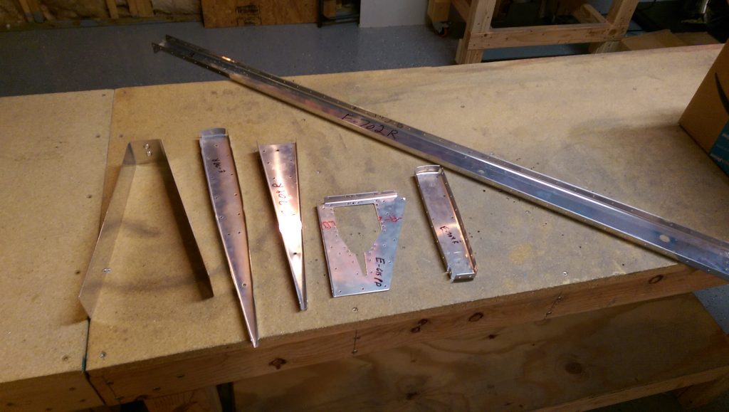
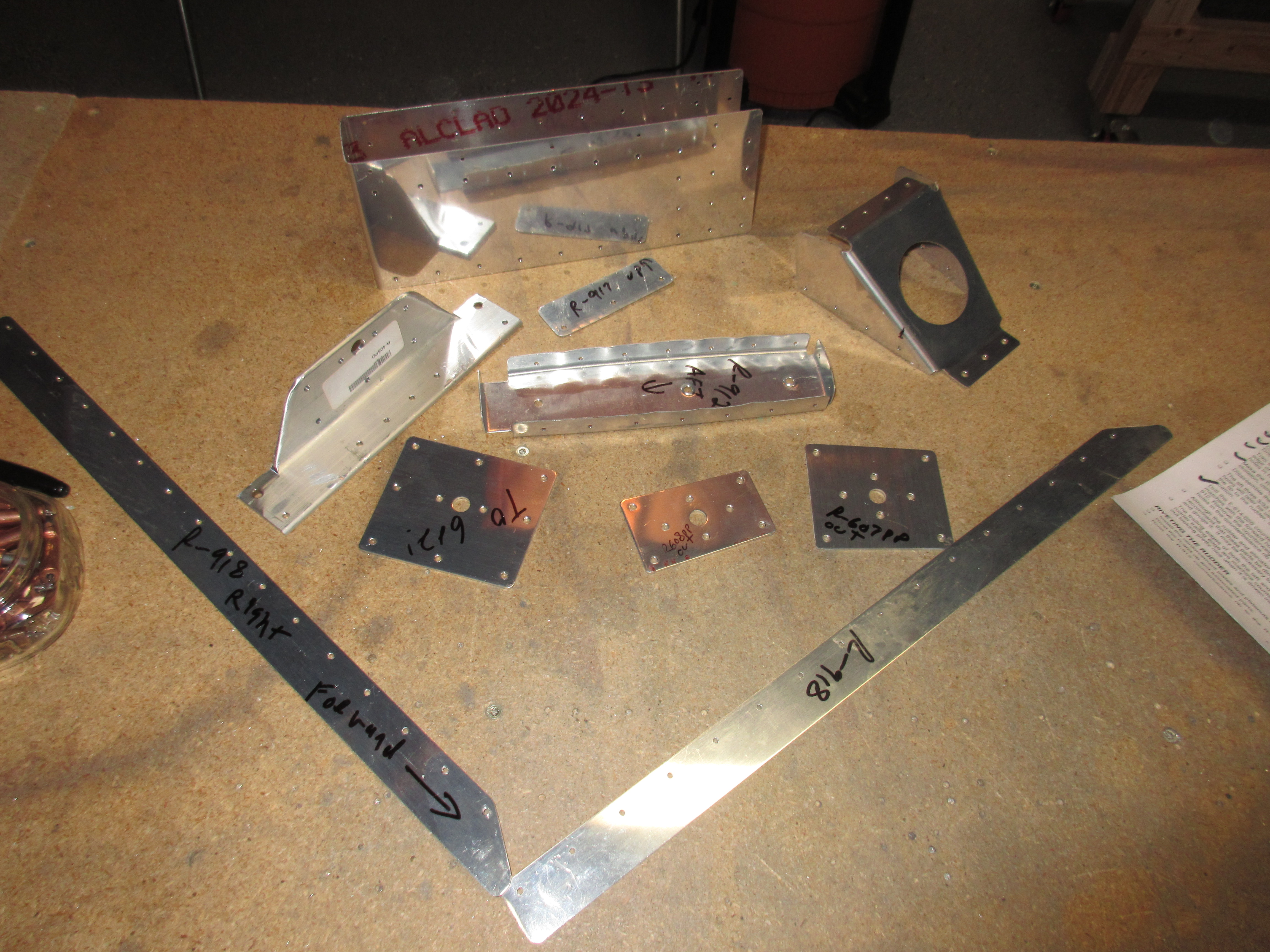
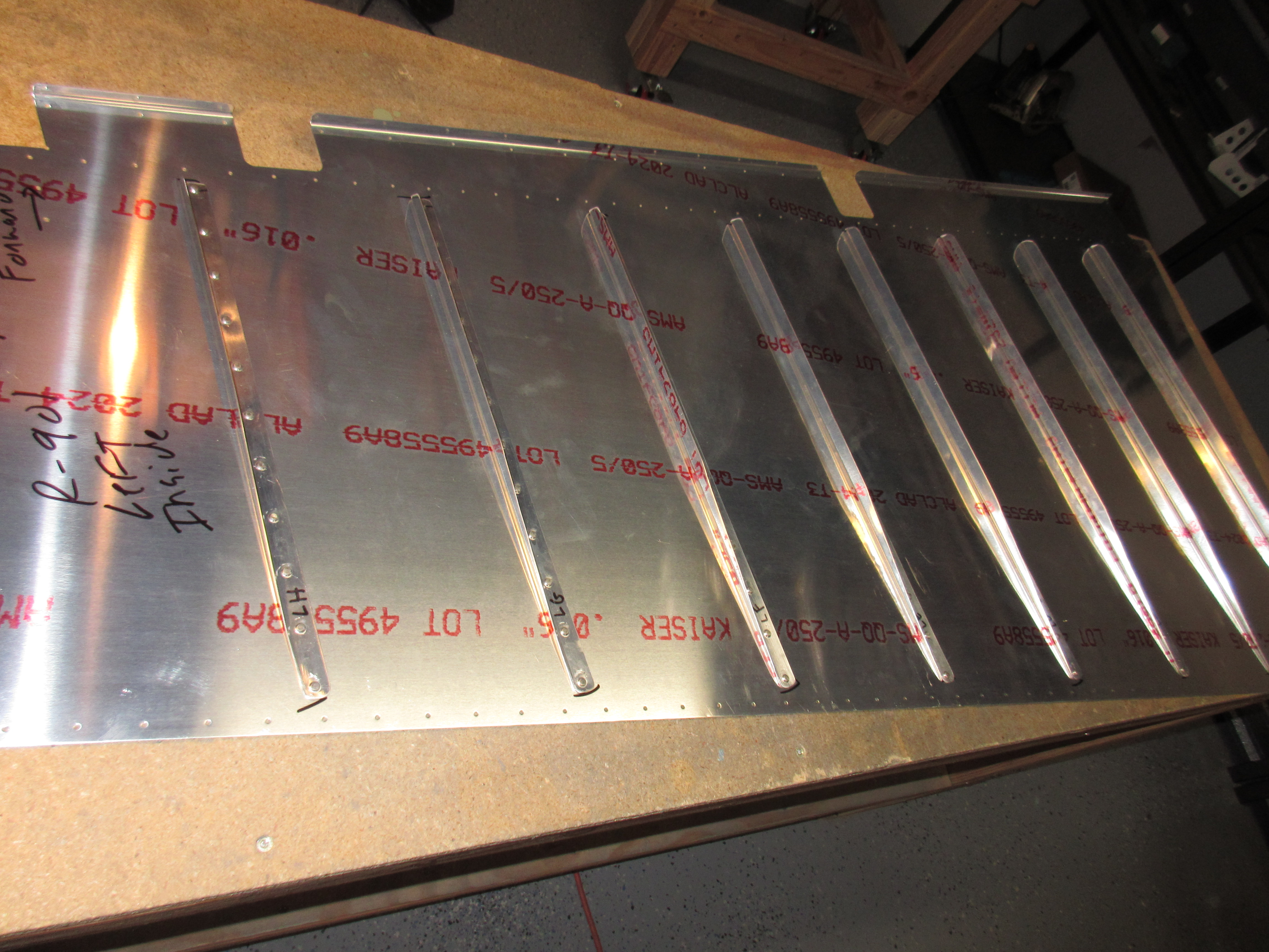
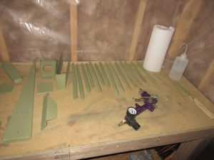
Priming and Stiffeners….the two things I like the least on this build. But, you can’t have an airplane unless you do these two things. I have been holding back several bits of work in order to batch all my priming into one big job, and tonight I planned to tackle this. I won’t be batching parts up any longer….more on that later. All in all, I had all the parts for the rudder (skins, stiffeners, skeleton and doublers) that needed to be primed, in addition to the right elevator skins, stiffeners, and skeleton. In hindsight, this was way to many parts to deal with in one session, and I don’t think I will batch this many up next time.
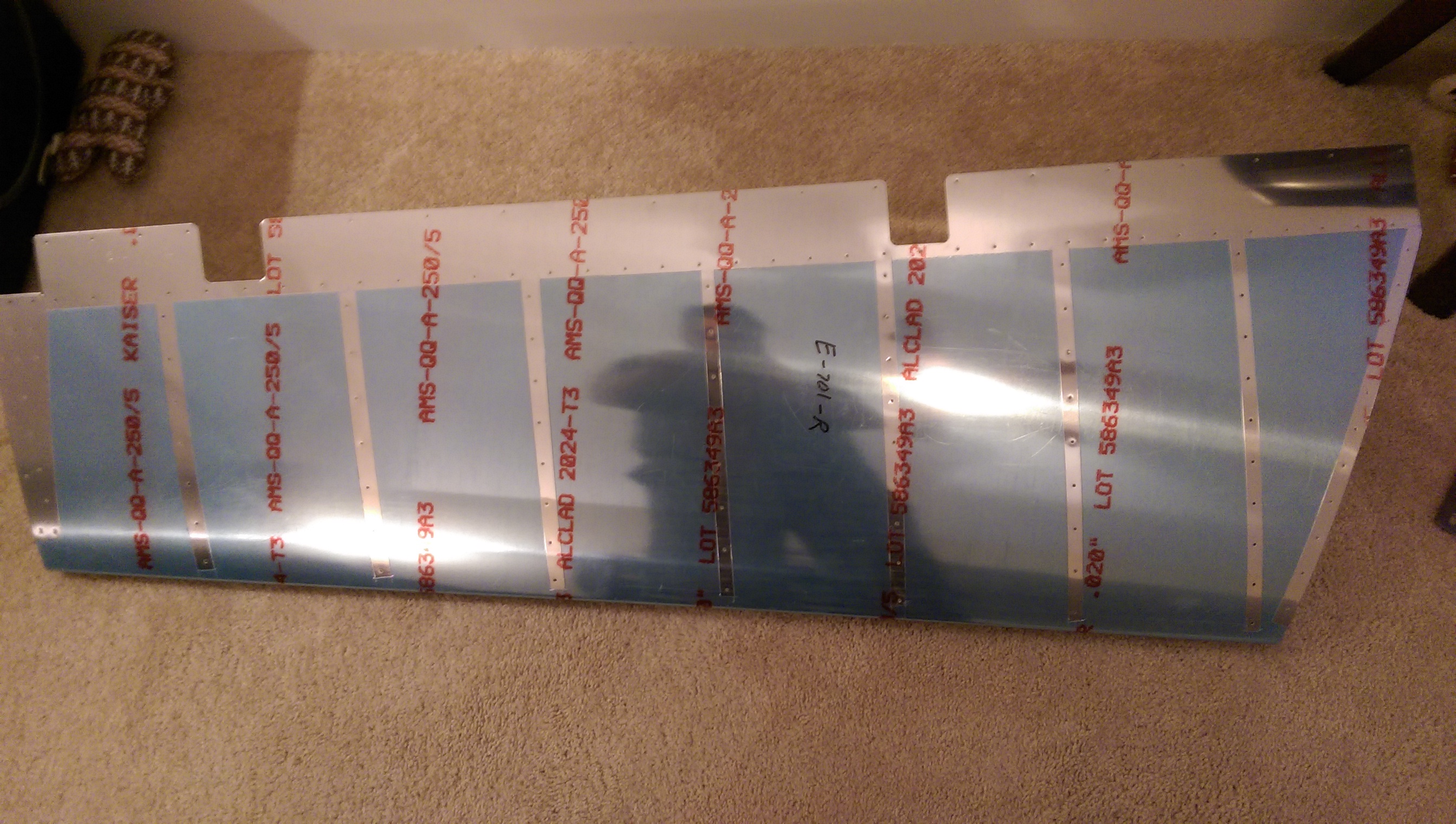
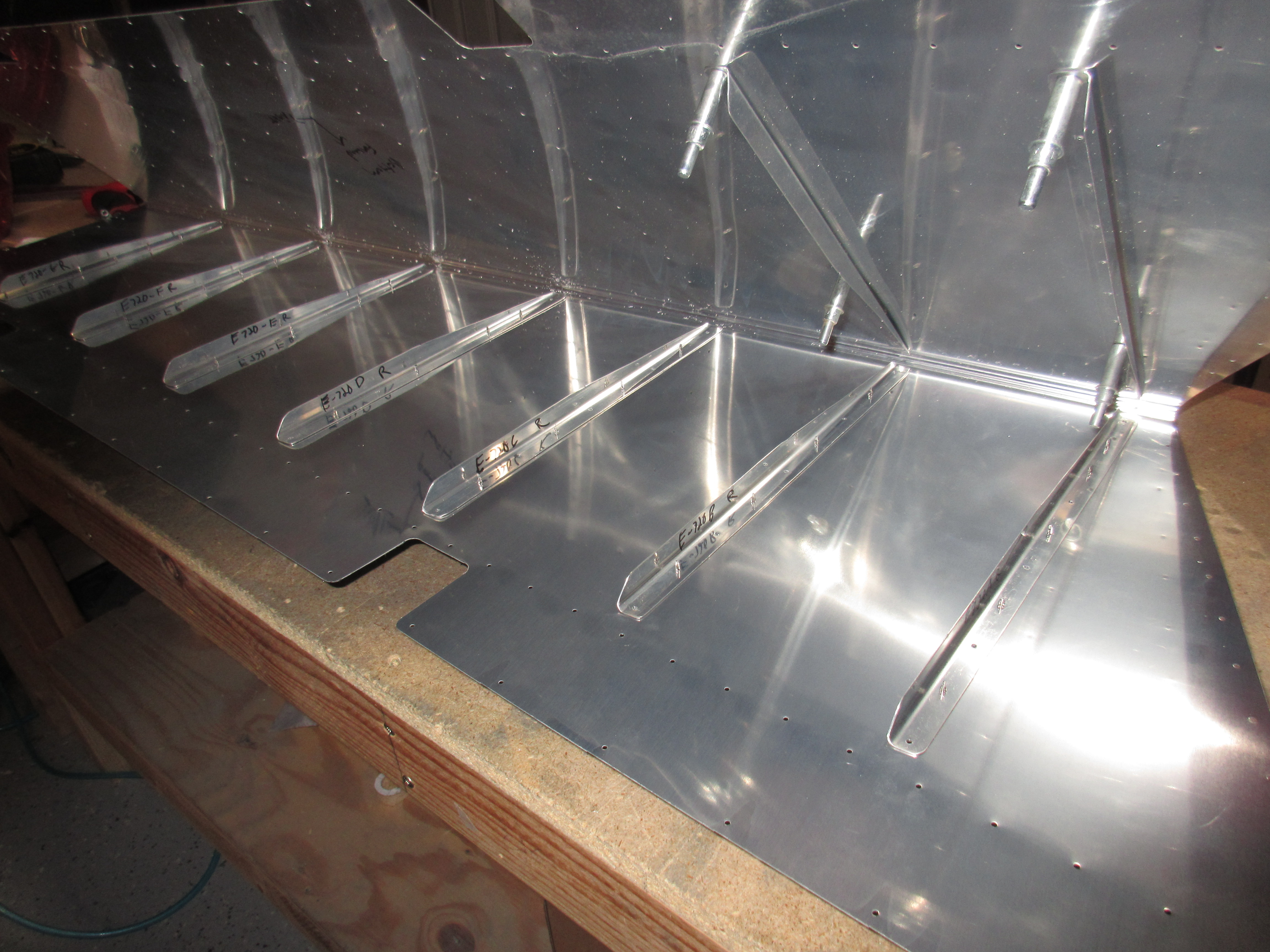
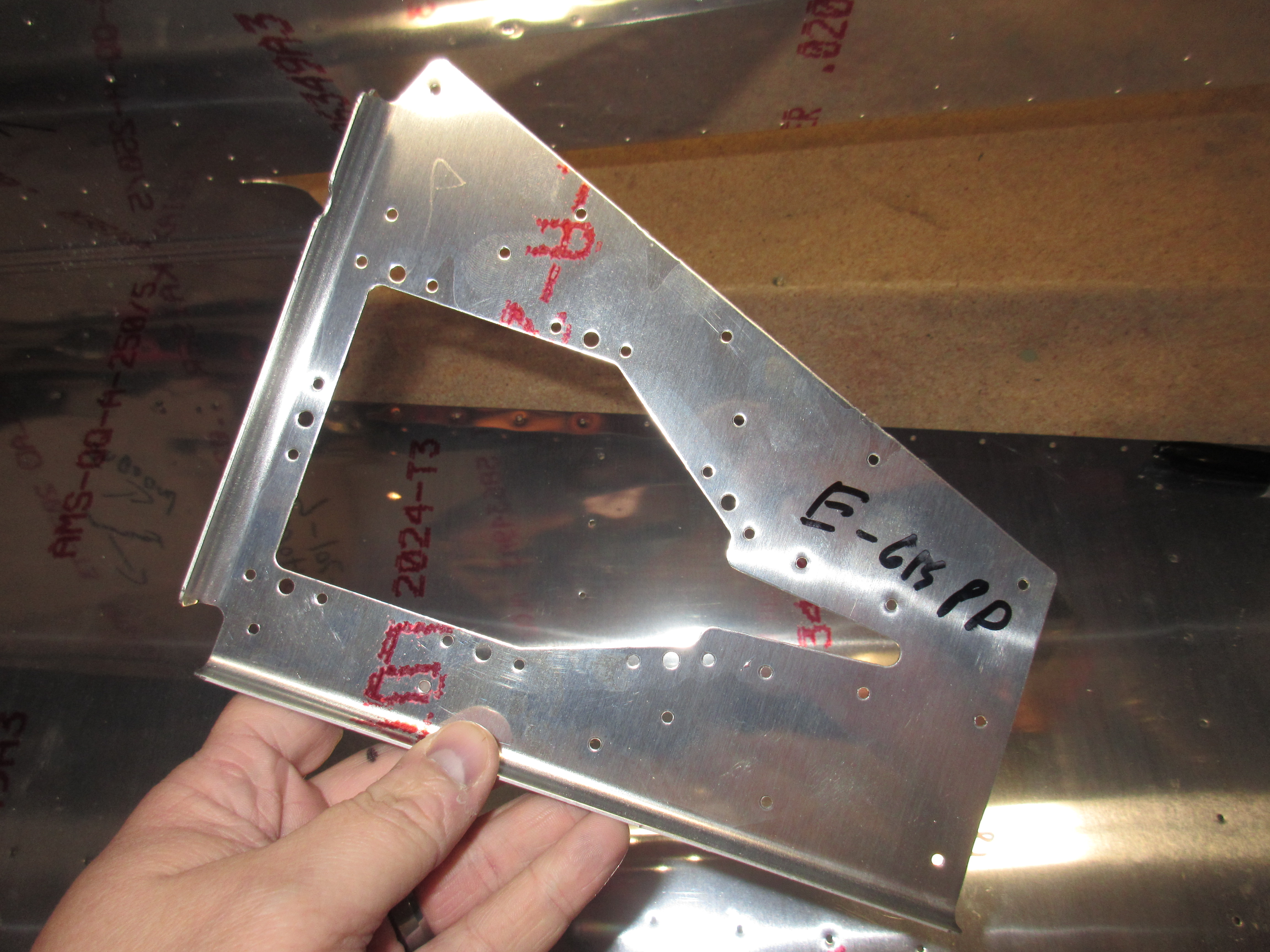
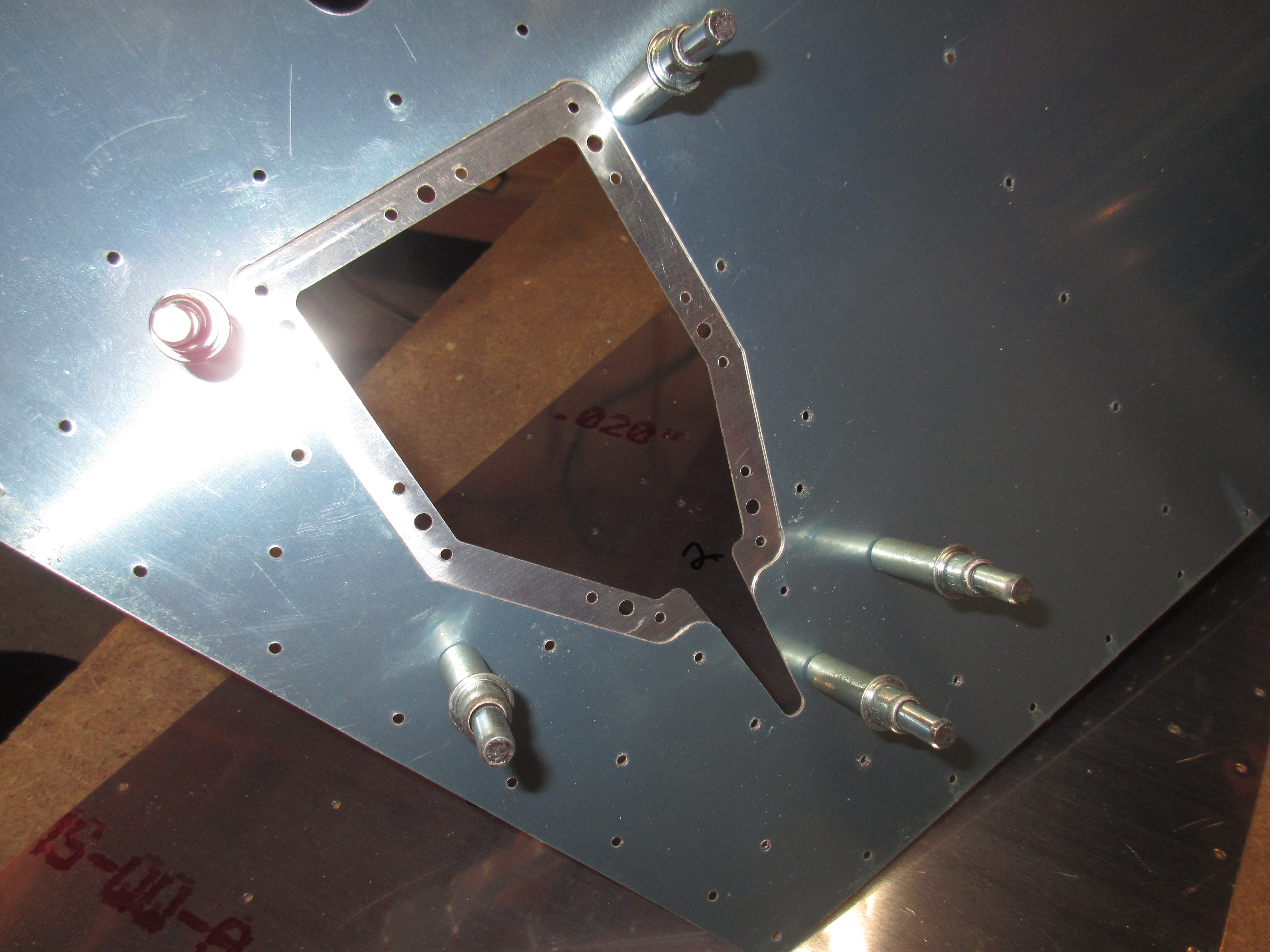
I started out by scuffing all the rudder parts with brown Scotchbrite pads first and then using a microfiber rag to clean the dust off. Then I put them in the paint booth to be cleaned with acetone before being primered. After the rudder, I gathered up all the right elevator parts and did the same procedure with them, making sure to keep these parts in a separate pile in the paint booth to avoid confusion with the rudder parts. This is where I should have stopped scuffing and went right into priming, but my wanting to get things done told me “go ahead and get the right elevator skin and stiffeners done while we are at it!!”. I already have these parts drilled and ready for priming, so I went ahead and added them in to the work. My hand was KILLING me by the time I was done with all that scuffing, and I still have to clean and prime all those parts!!! Since I had scuffed away the Alclad and the oxidation layer, I couldn’t leave them overnight, because they would oxidize again, and I would have to scuff again. I powered through the pain of a cramping hand and kept working. 🙂
Now I had all my parts in nice neat stacks in the paint booth, I went ahead and proceeded with the work of cleaning the with acetone to remove oils and residue, cleaning with paper towels until the towel came back clean with no black on them. With scuffed and cleaned parts I was ready to prime! I learned tonight that I absolutely despise all these little stiffeners, they are so fiddly to scuff and clean! I need to find a better solution to this nagging problem.
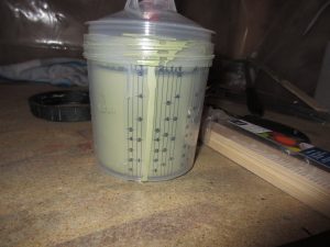
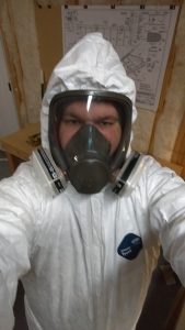
I mixed up a full 20 ounces of AKZO primer in my PPS cup. I figured I would use most, if not all, of the primer so I filled it up with equal parts A and B, and let the mixture sit for the 30 minutes to activate. I used this time to put on a full Tyvek suit with booties and hood, and then donned a full face respirator with really good 3M filters designed for spray painting, and organic vapors. Then, setup my parts on the spray table and closed up the paint booth.
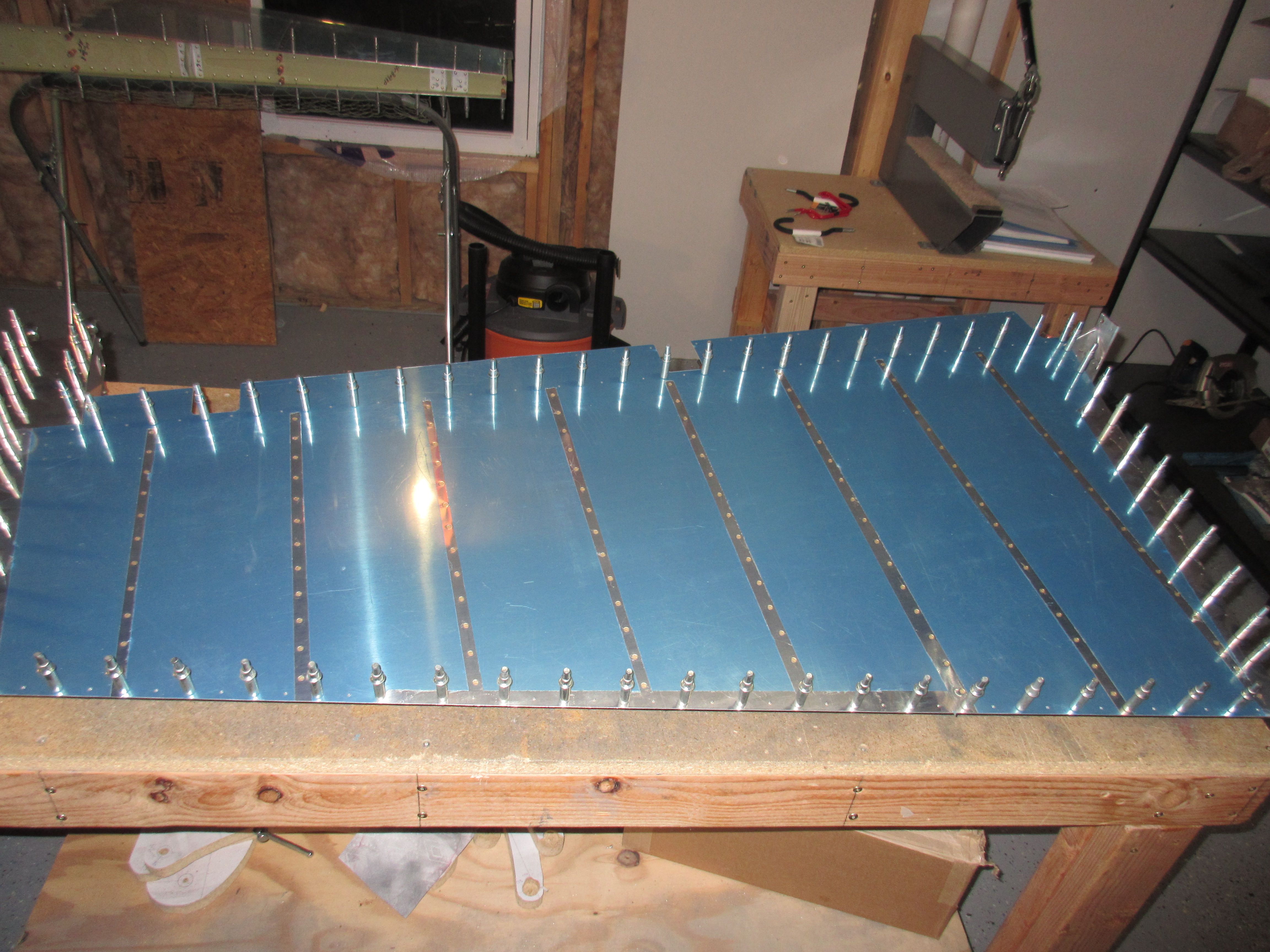
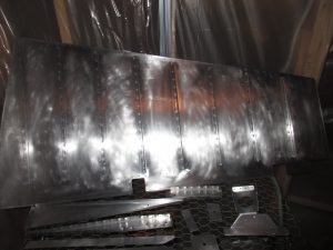
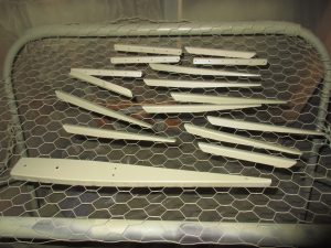
After about 45 minutes of spraying parts, I had everything done and looking good. As usual, the first spray was a little heavy and ran a bit on the rudder trailing edge, but I’m not worried about it since its primer and on the inside of the rudder, no one will see it. AKZO sprays really easily, and drys quick making it super easy to use. Now, I’ll let the parts lay up in the booth to cure over the next couple of days. I’m going to put an order in for some ProSeal and pickup some angle aluminum to get ready for riveting the rudder trailing edge.
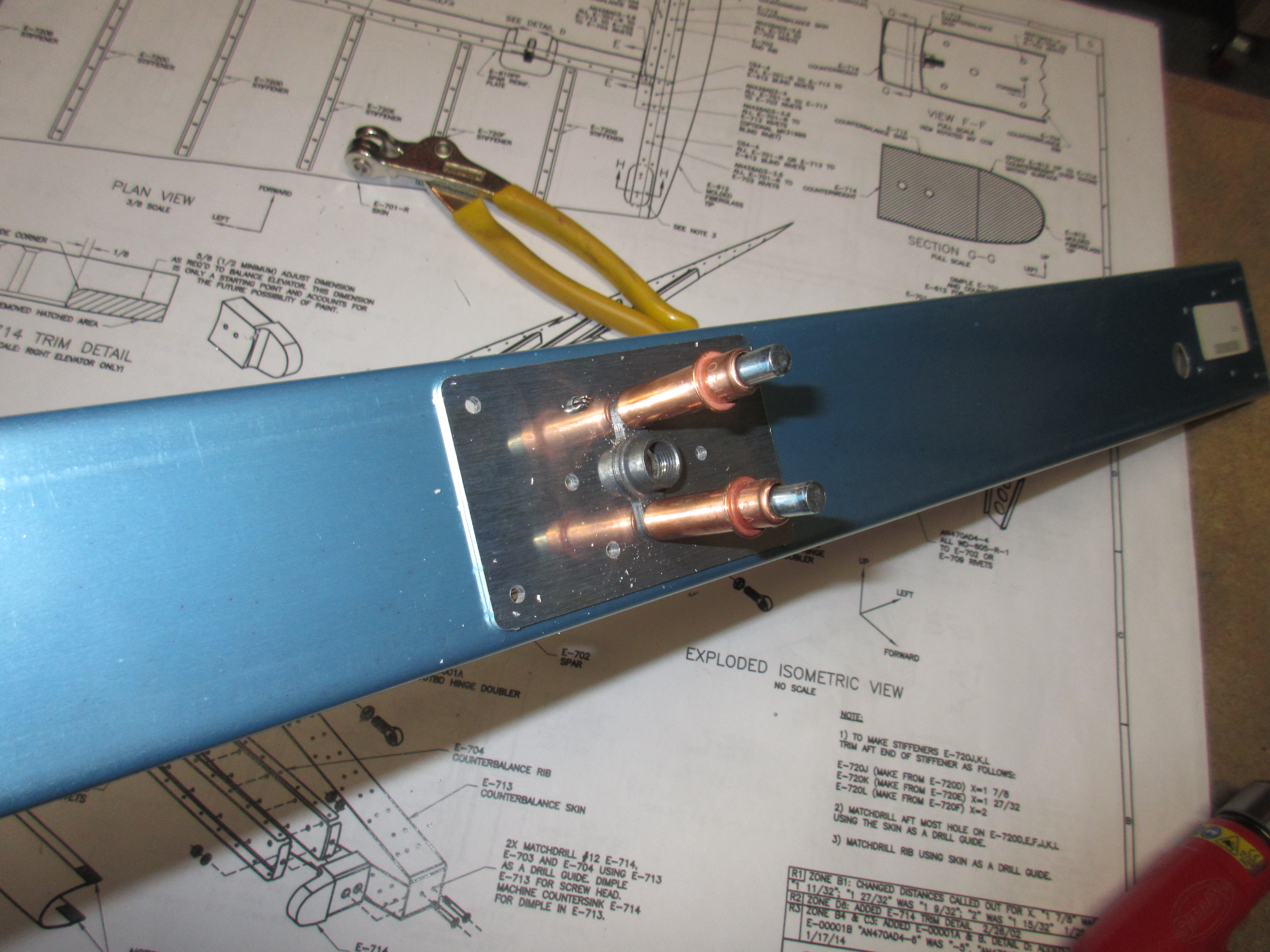
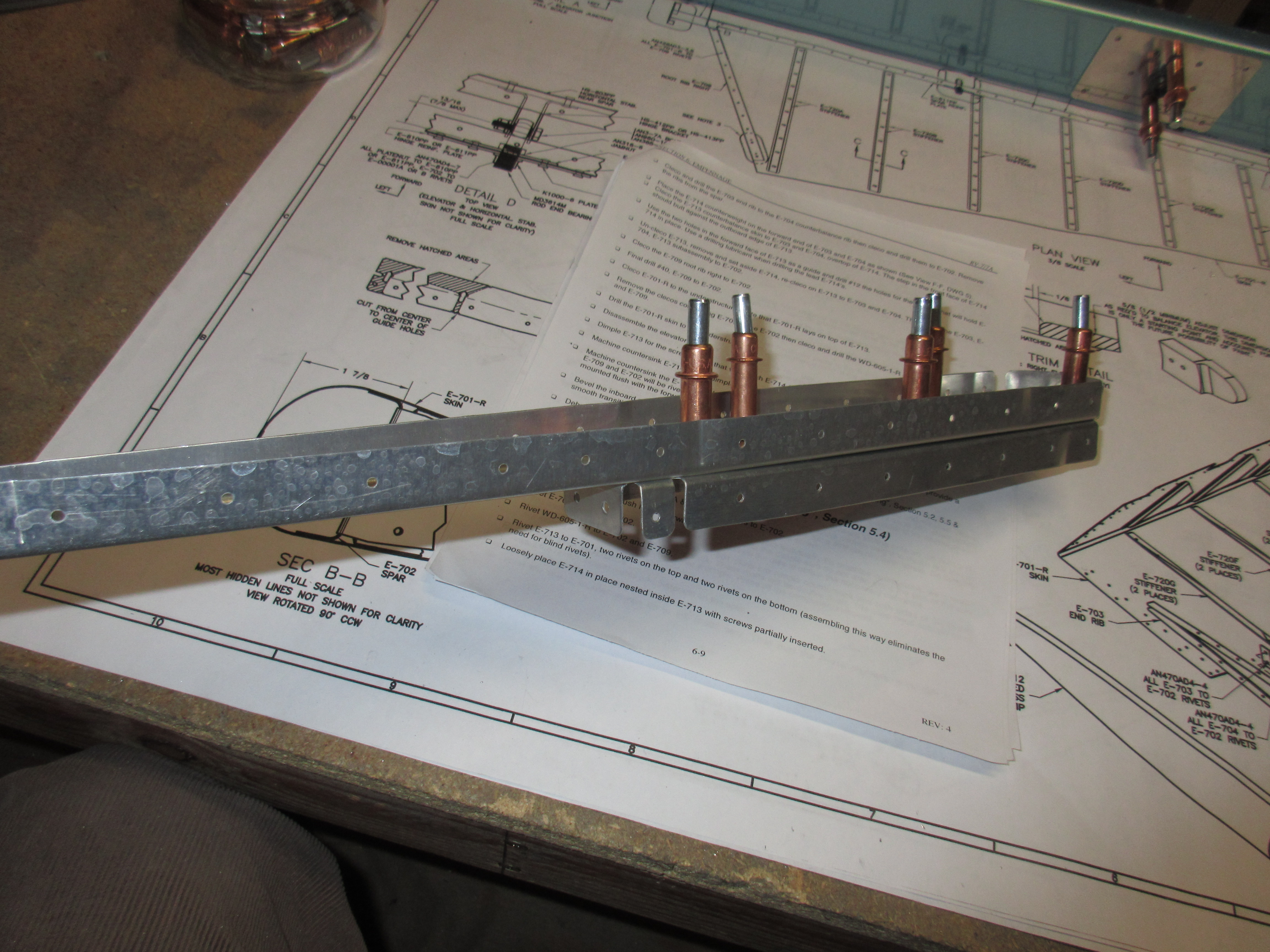
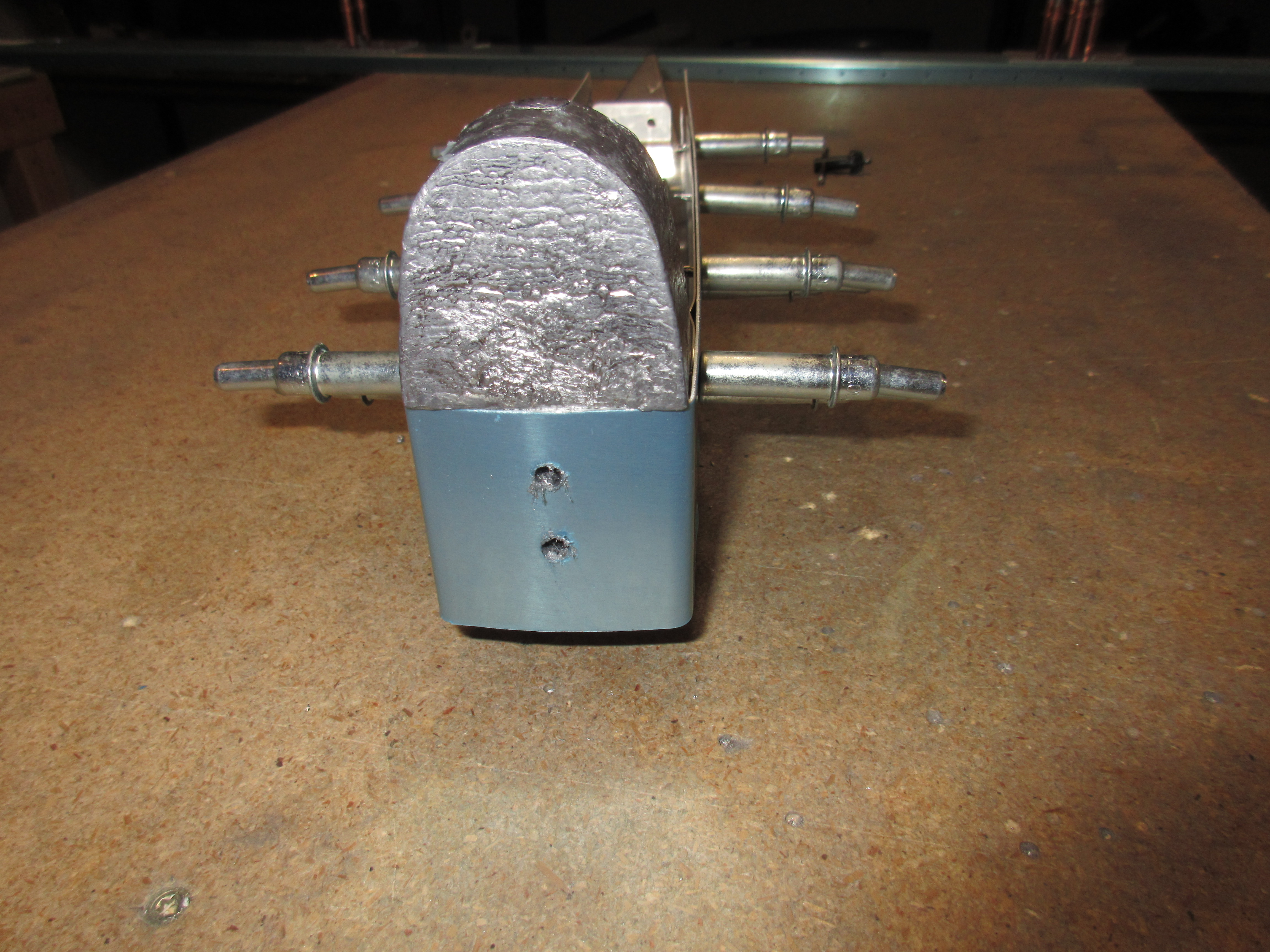
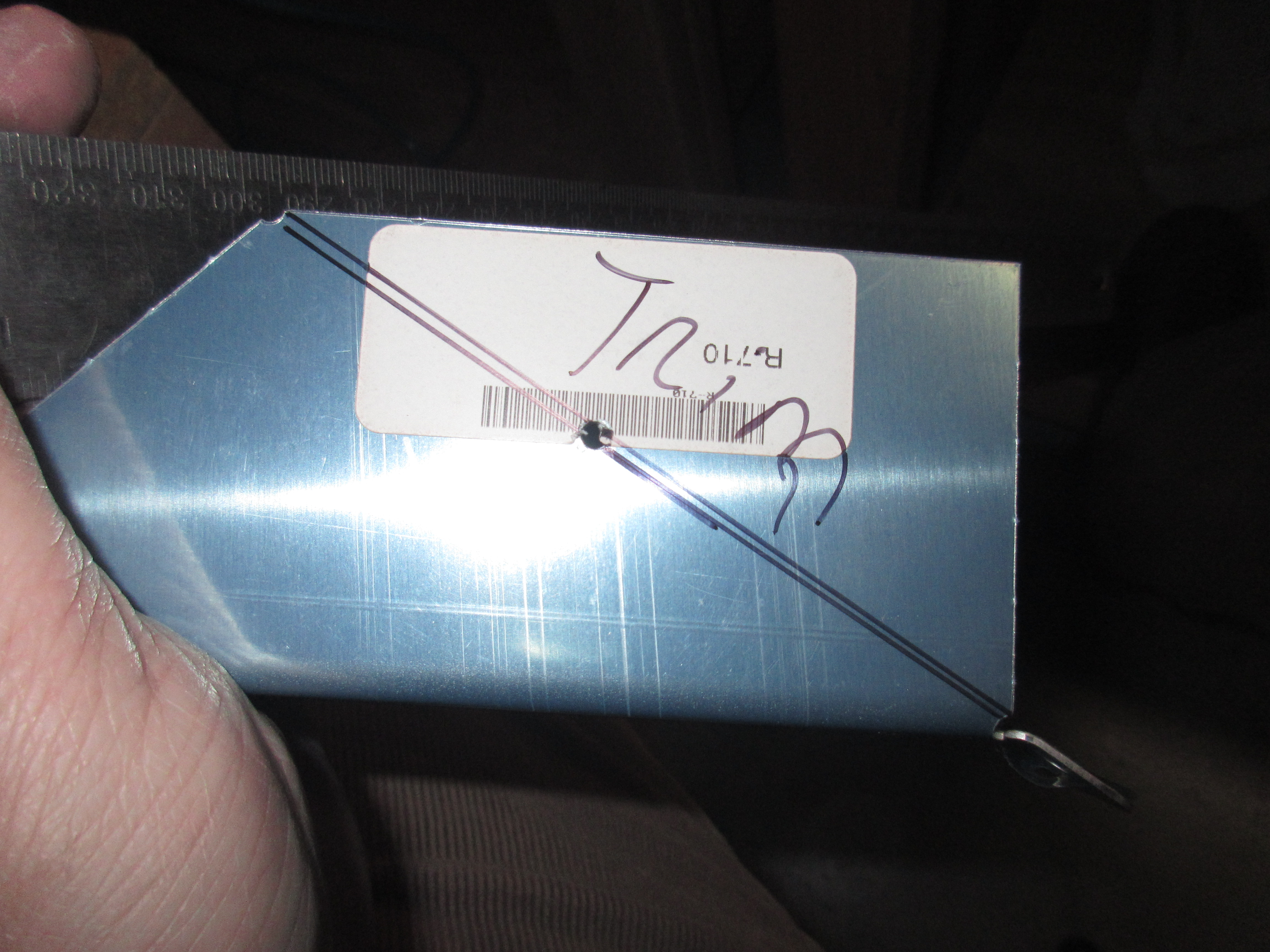
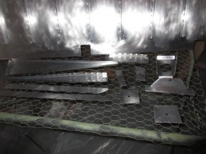
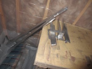
Heres all the photos from tonights work:
And heres the Google Photos album link: https://goo.gl/photos/6Ac2yeEXDjRy2RPD6
Hours Worked: 5.75