


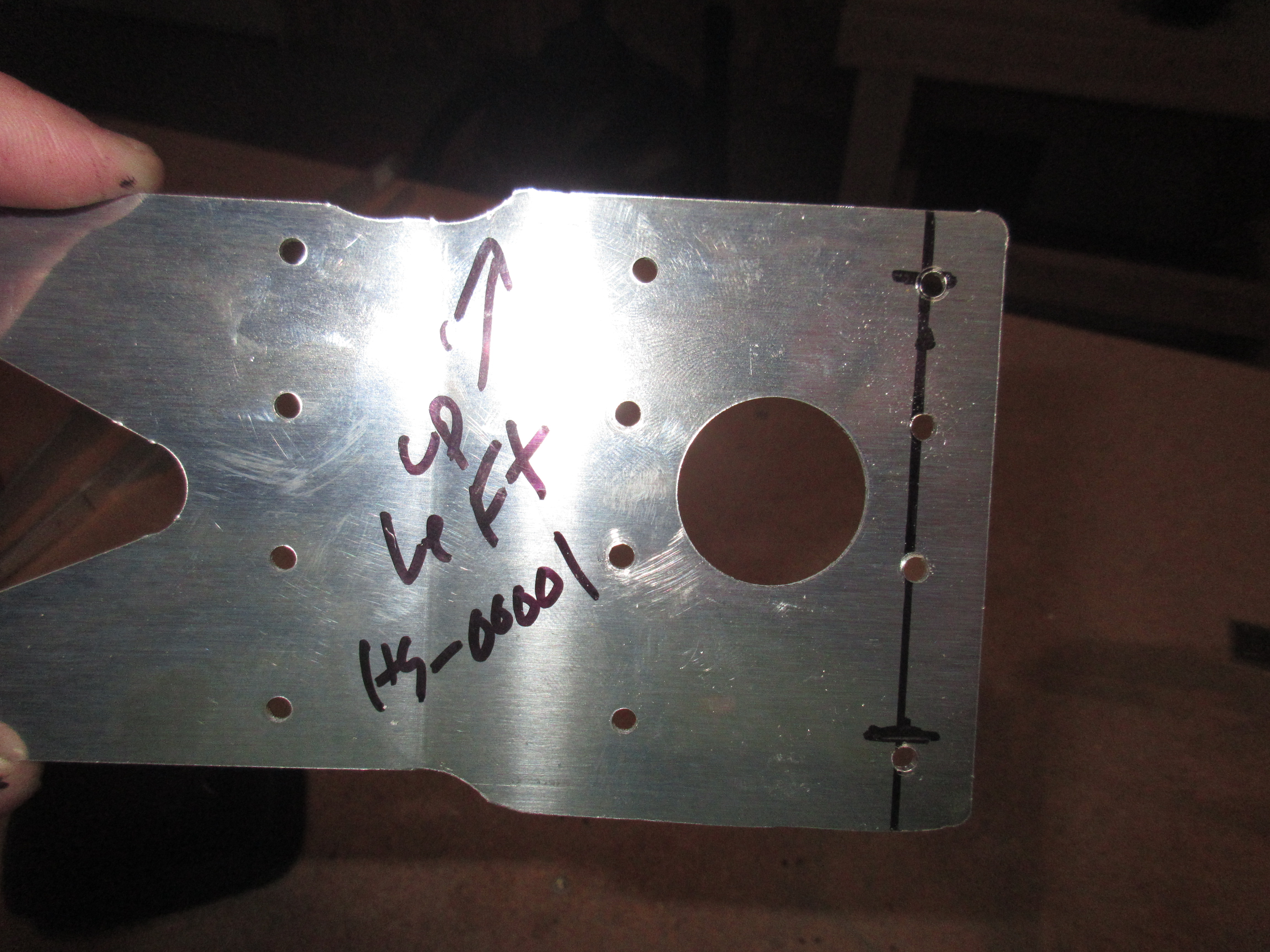
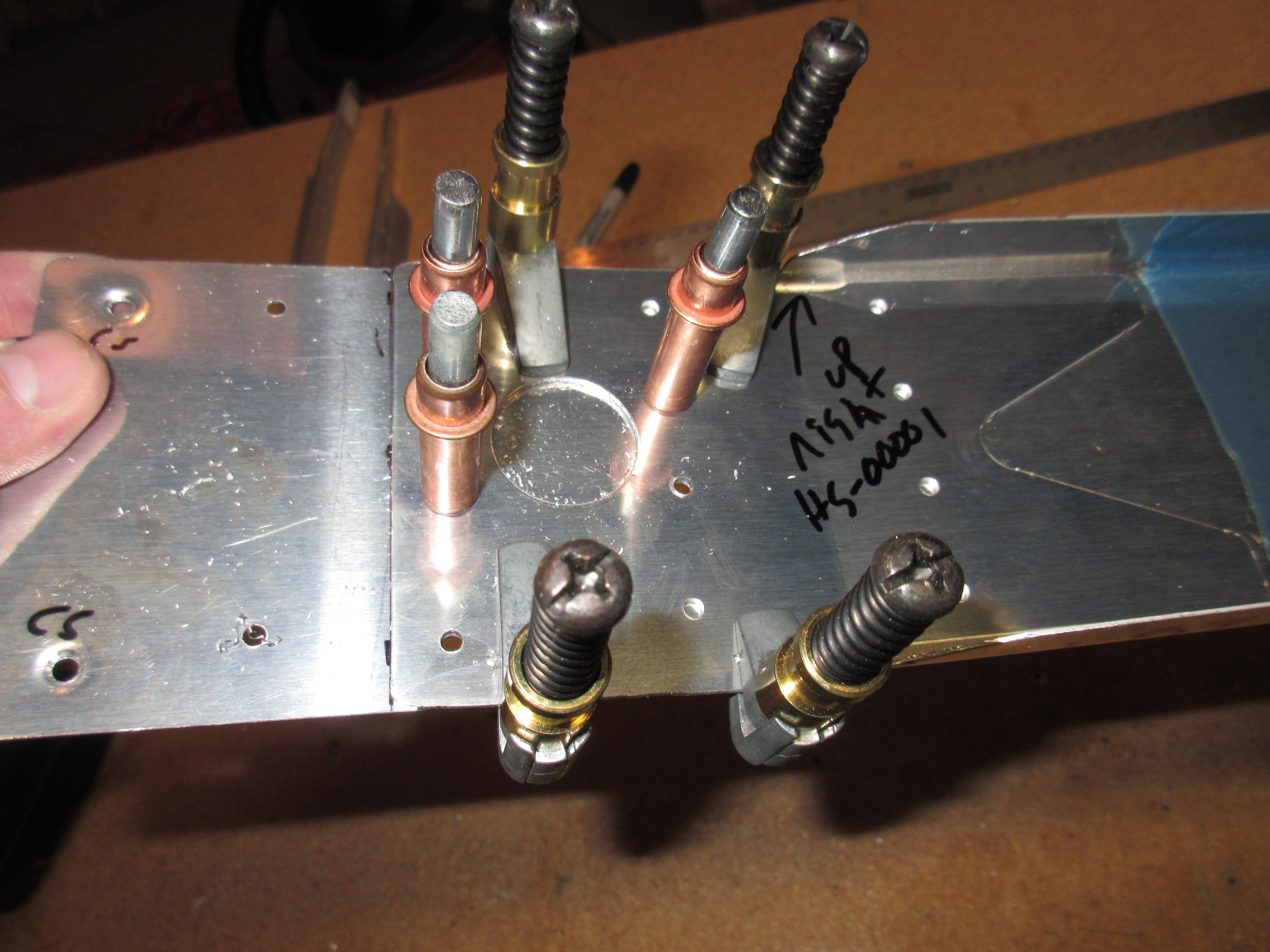
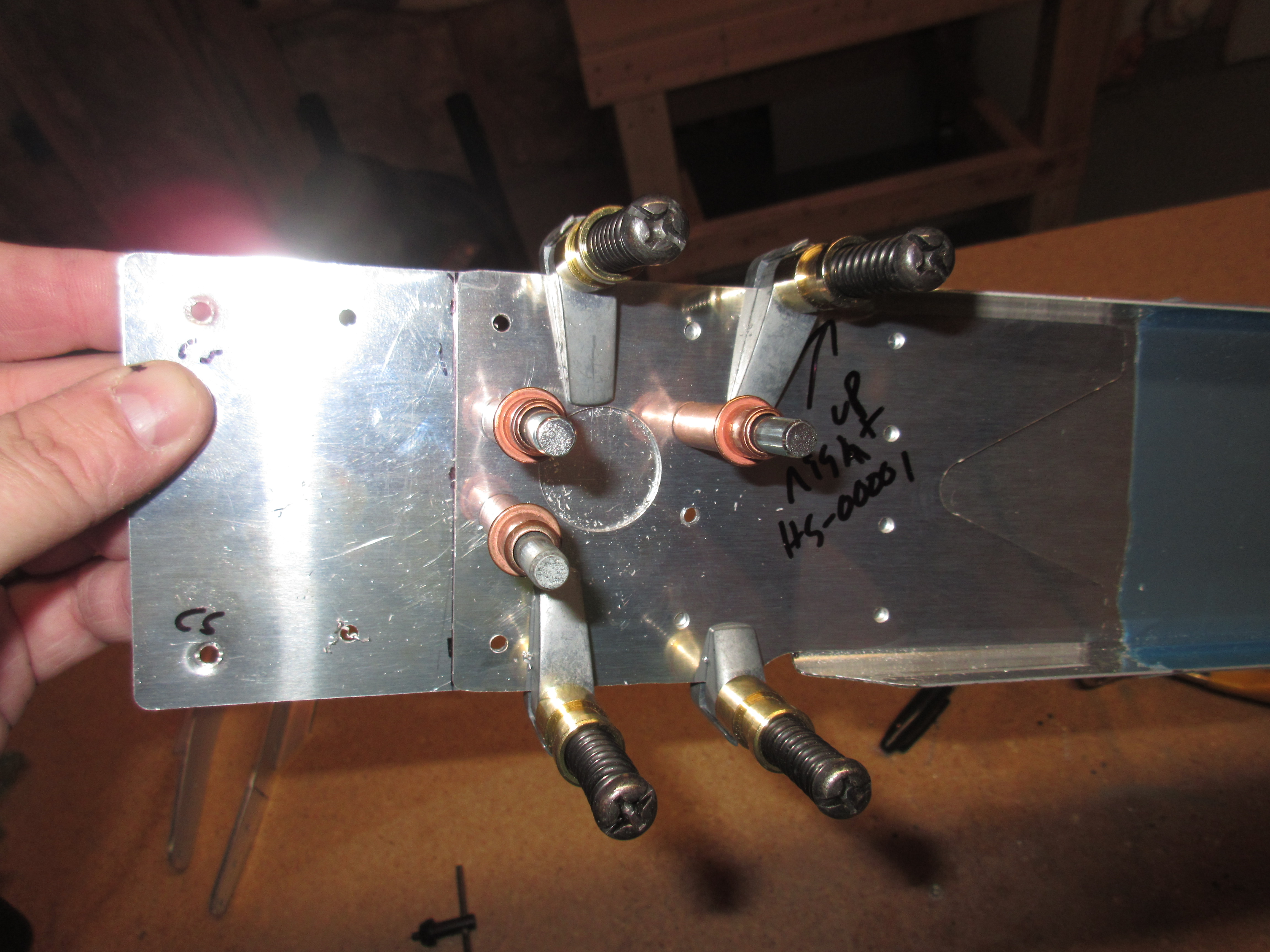
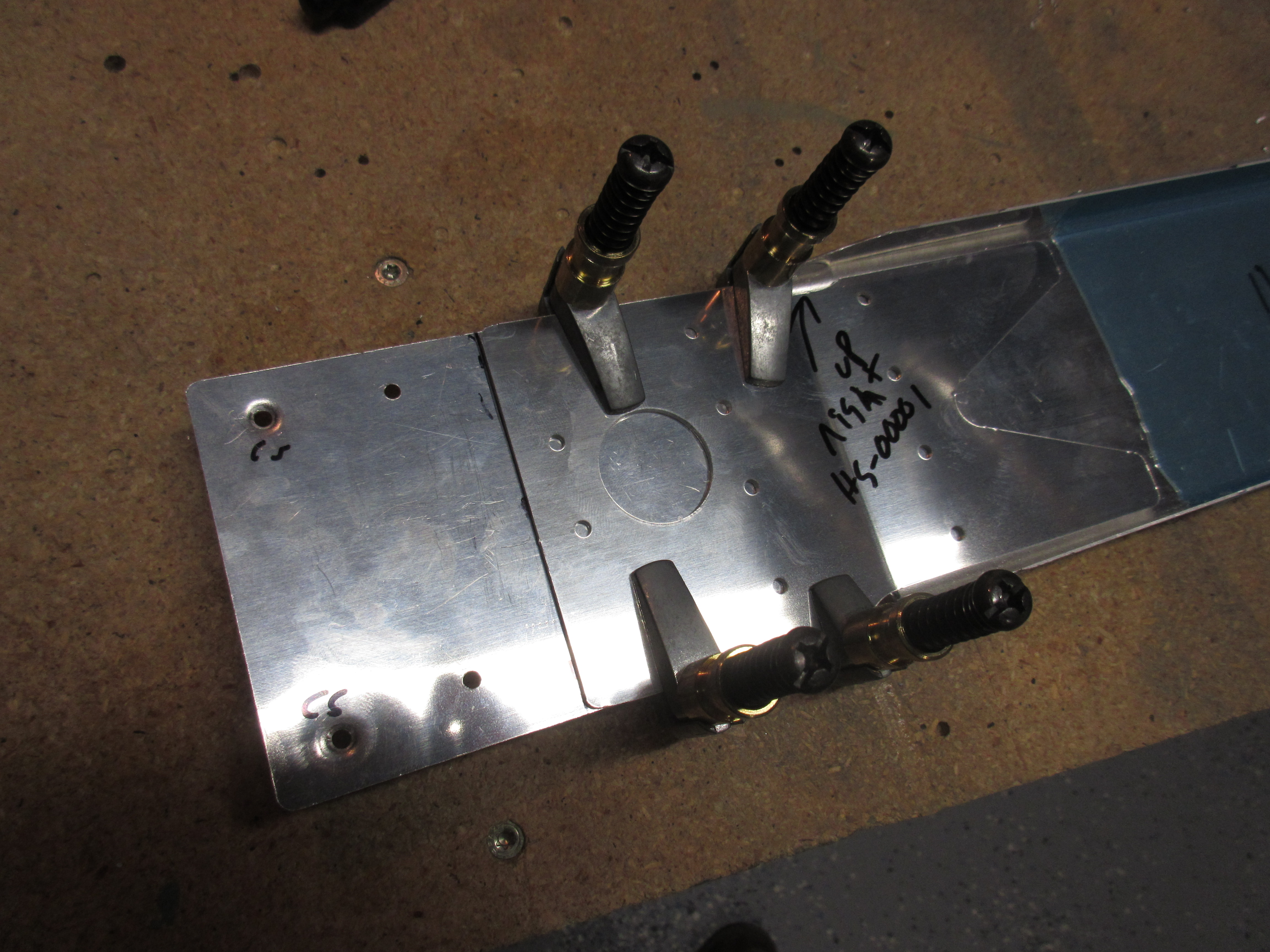
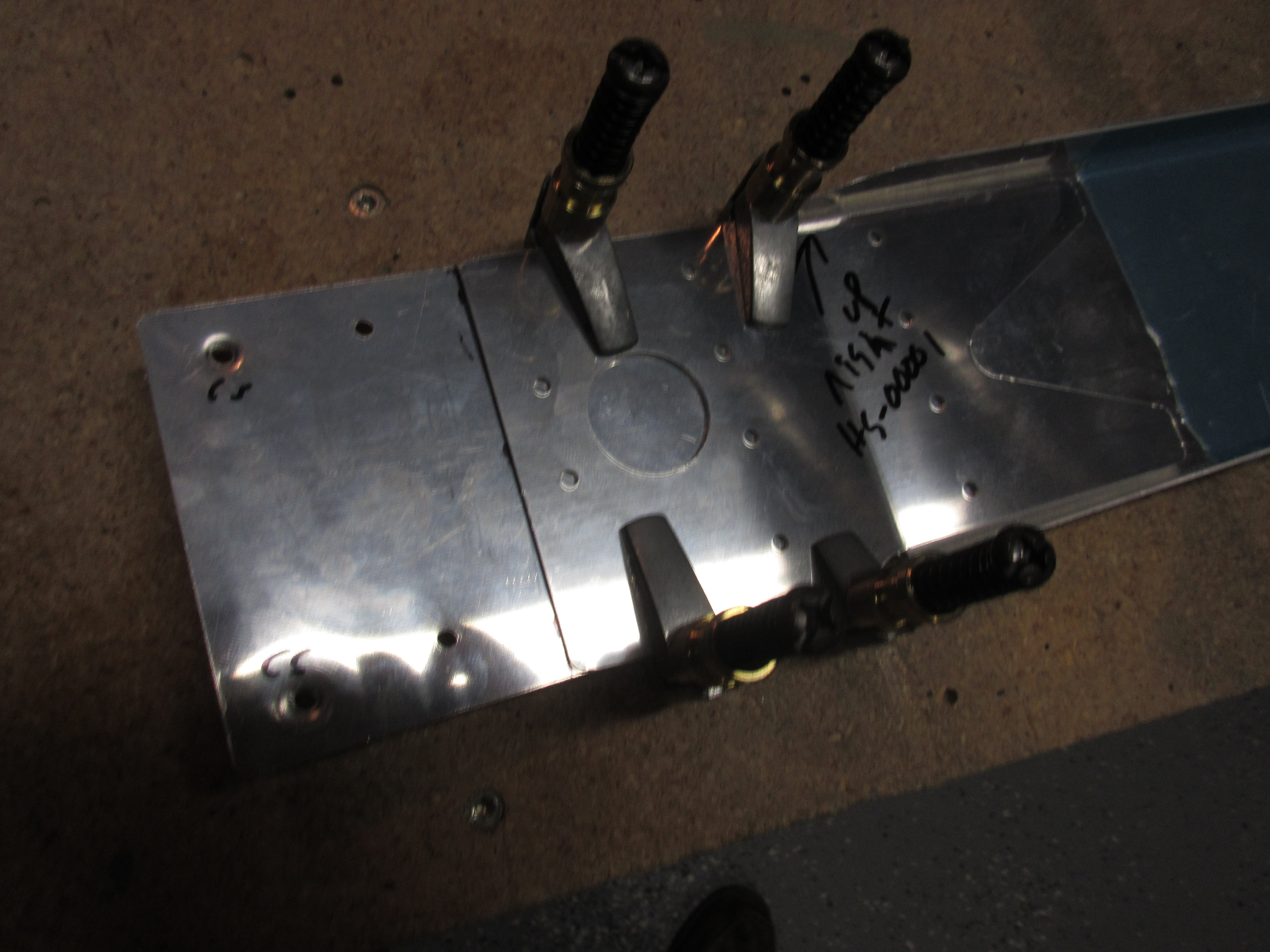
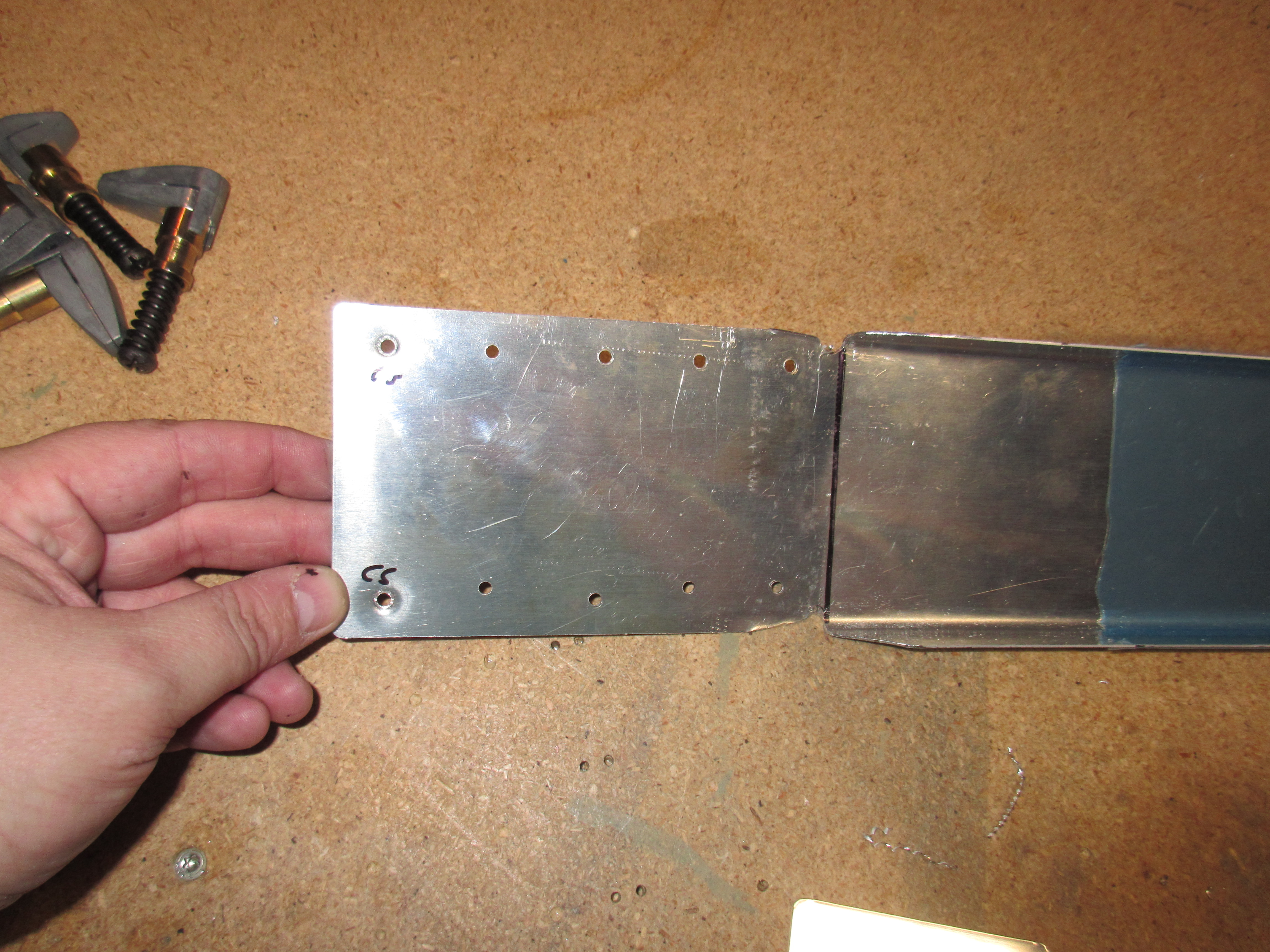
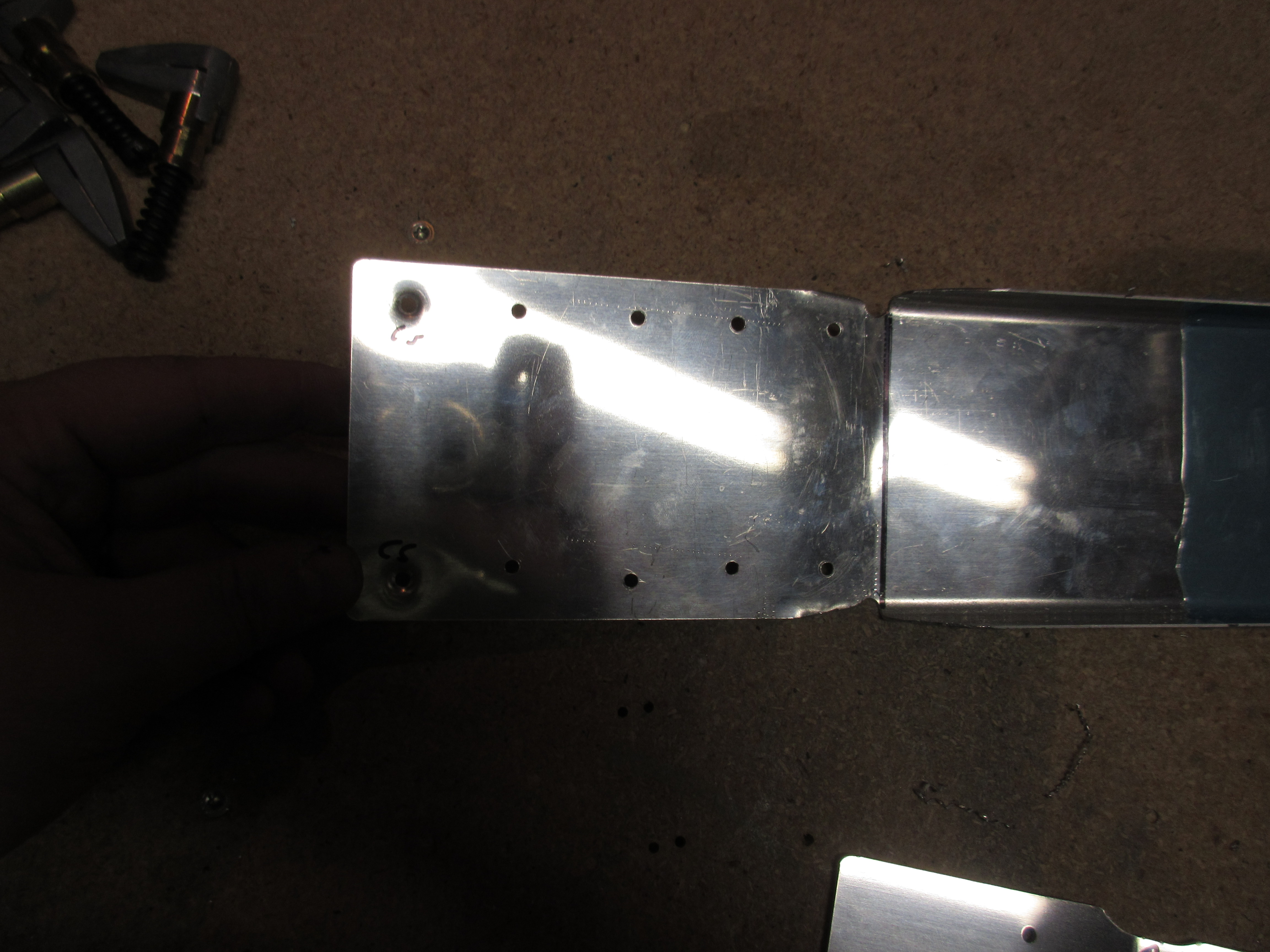
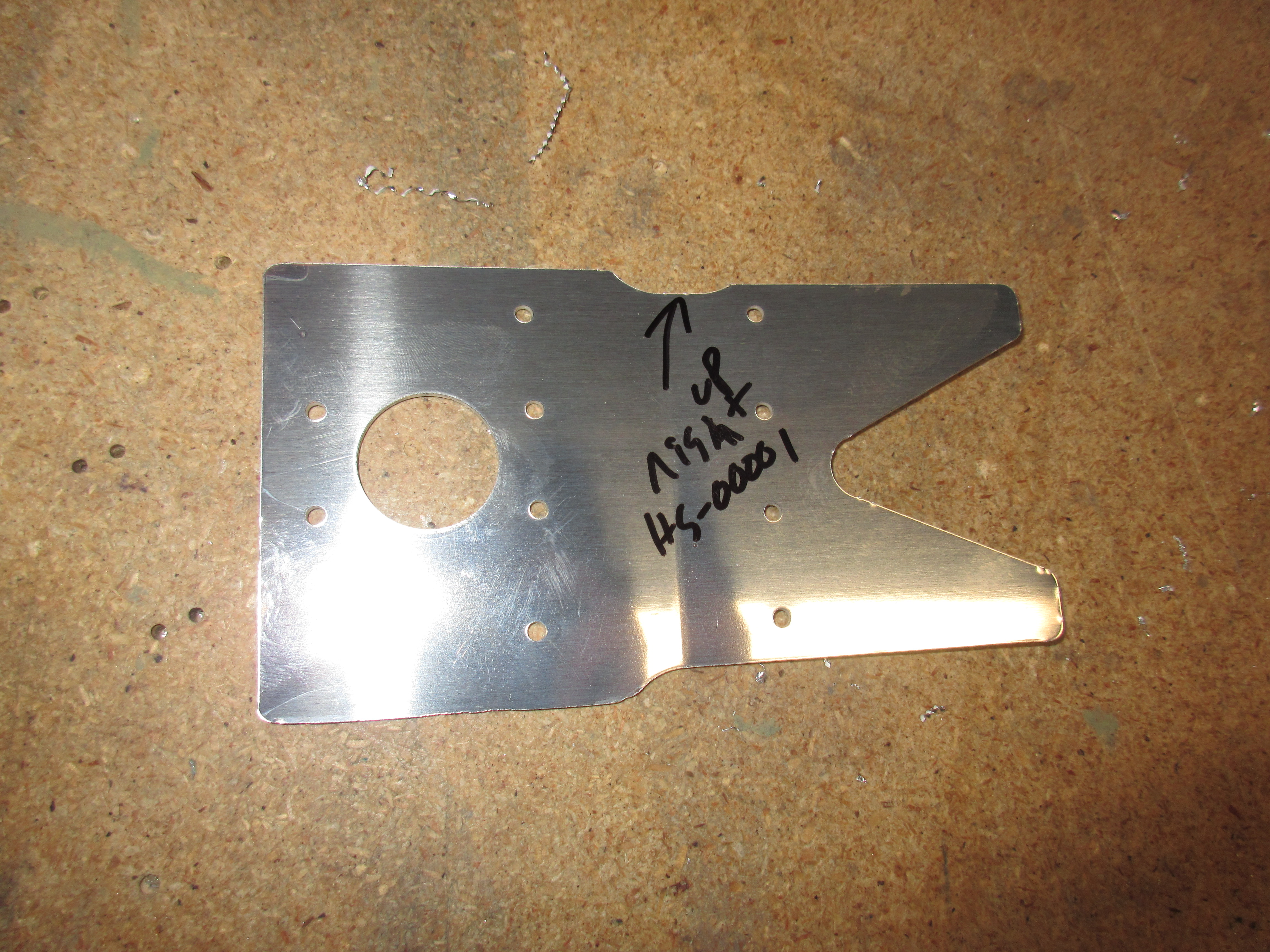
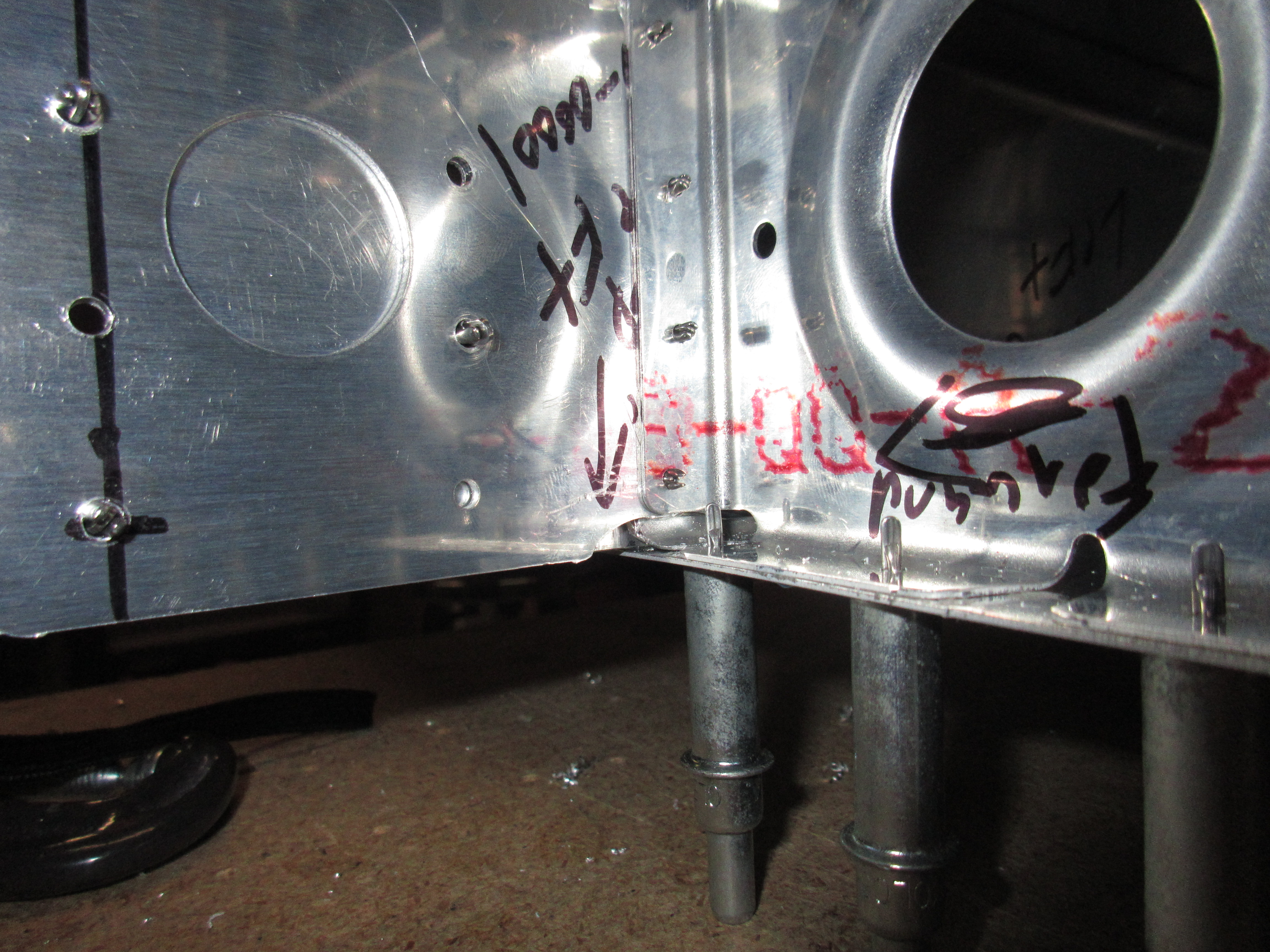
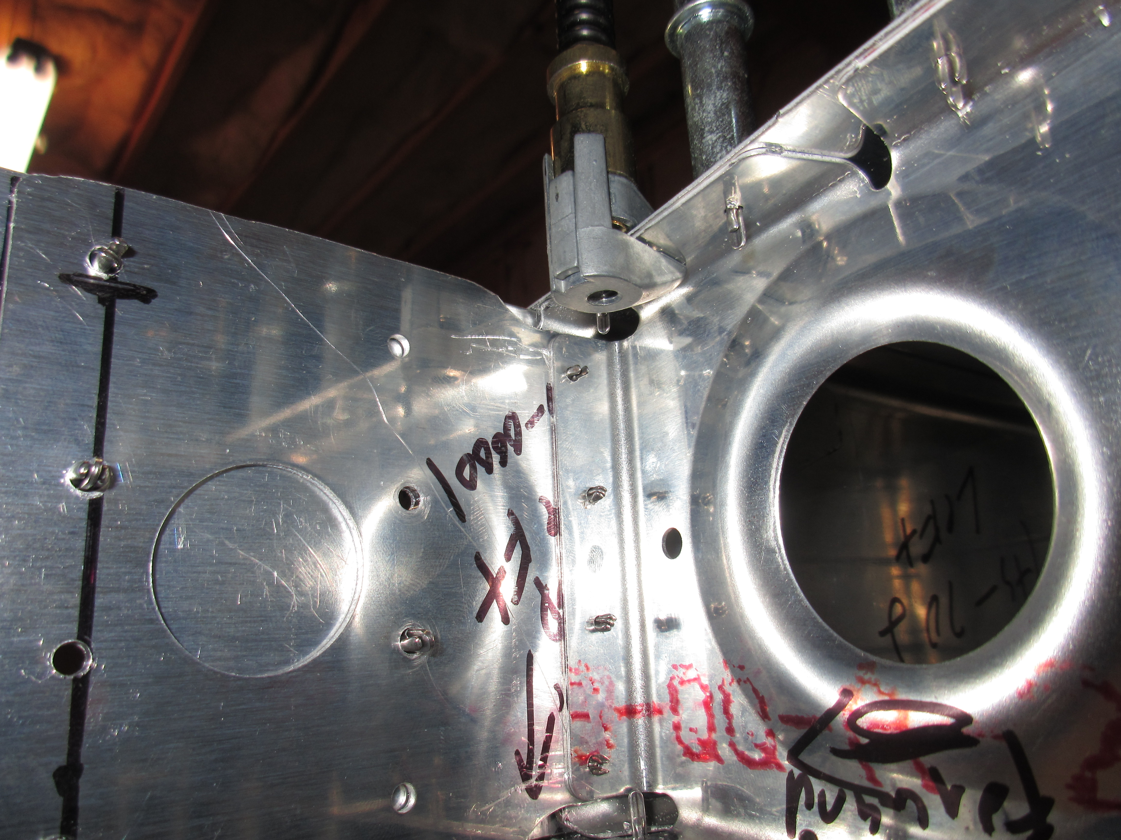
source link Today was a good day on the project, with lots of progress being made, and ultimately a flying surface assembled. Tonights work began with going back a few steps in the plans to assemble the HS-00001 doubler plate to the front spar. I measured out where the edges should be per the plans, and clamped them in place to drill their rivet holes. Once I had both sides done, I marked that step done in the plans and moved on.
https://www.52editions.com/raises/ I started the section in the plans called “Drilling the Horizontal Stabilizer”. I spent a good bit of the time today just looking over the plans and laying out the parts to get an idea of how it all should look and how I should drill out the front spar and spar doublers. Over the short break from the last session I read up SB for the front spar to learn how it should be assembled and drilled. It wasn’t as bad as I thought.
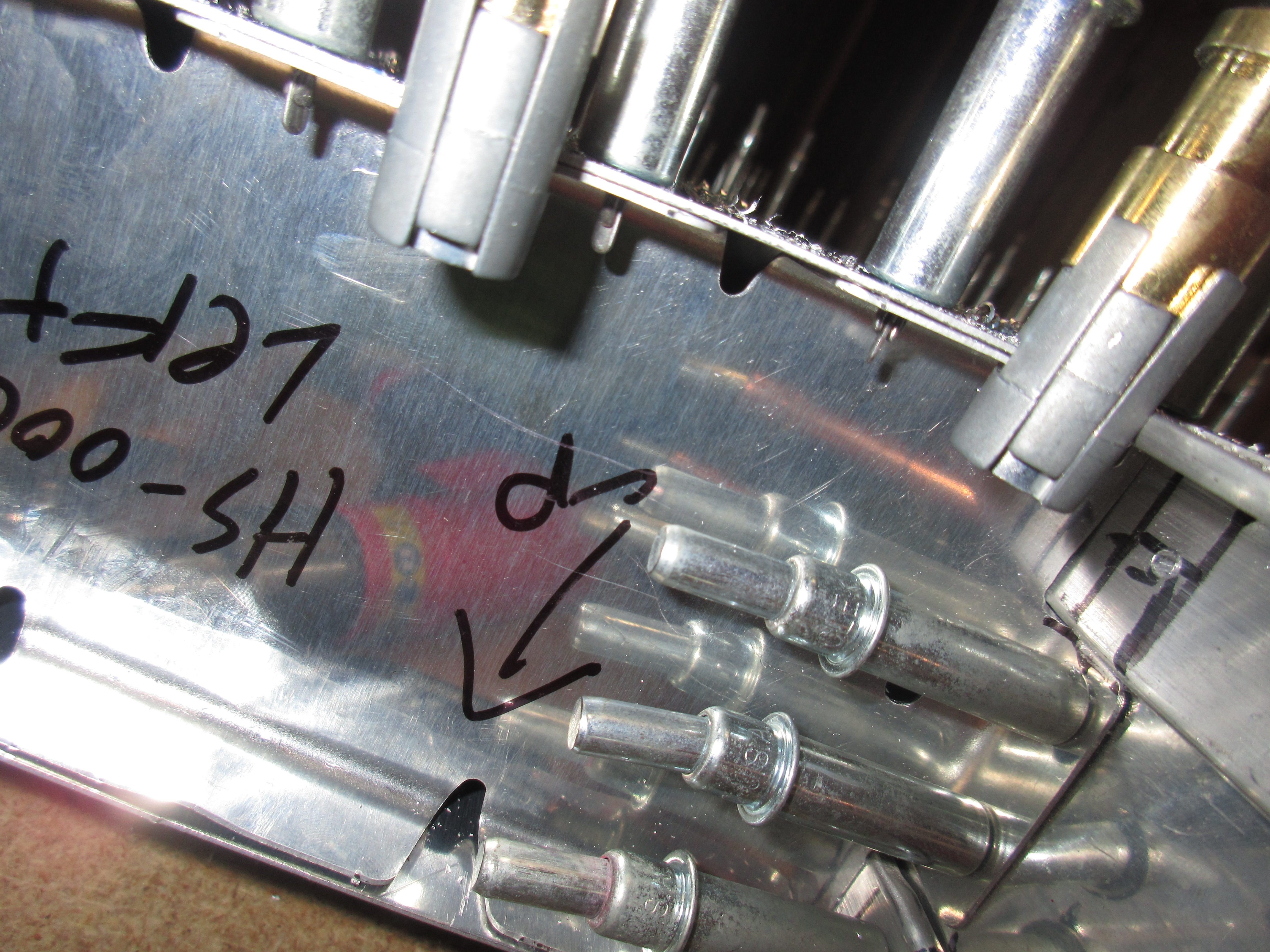
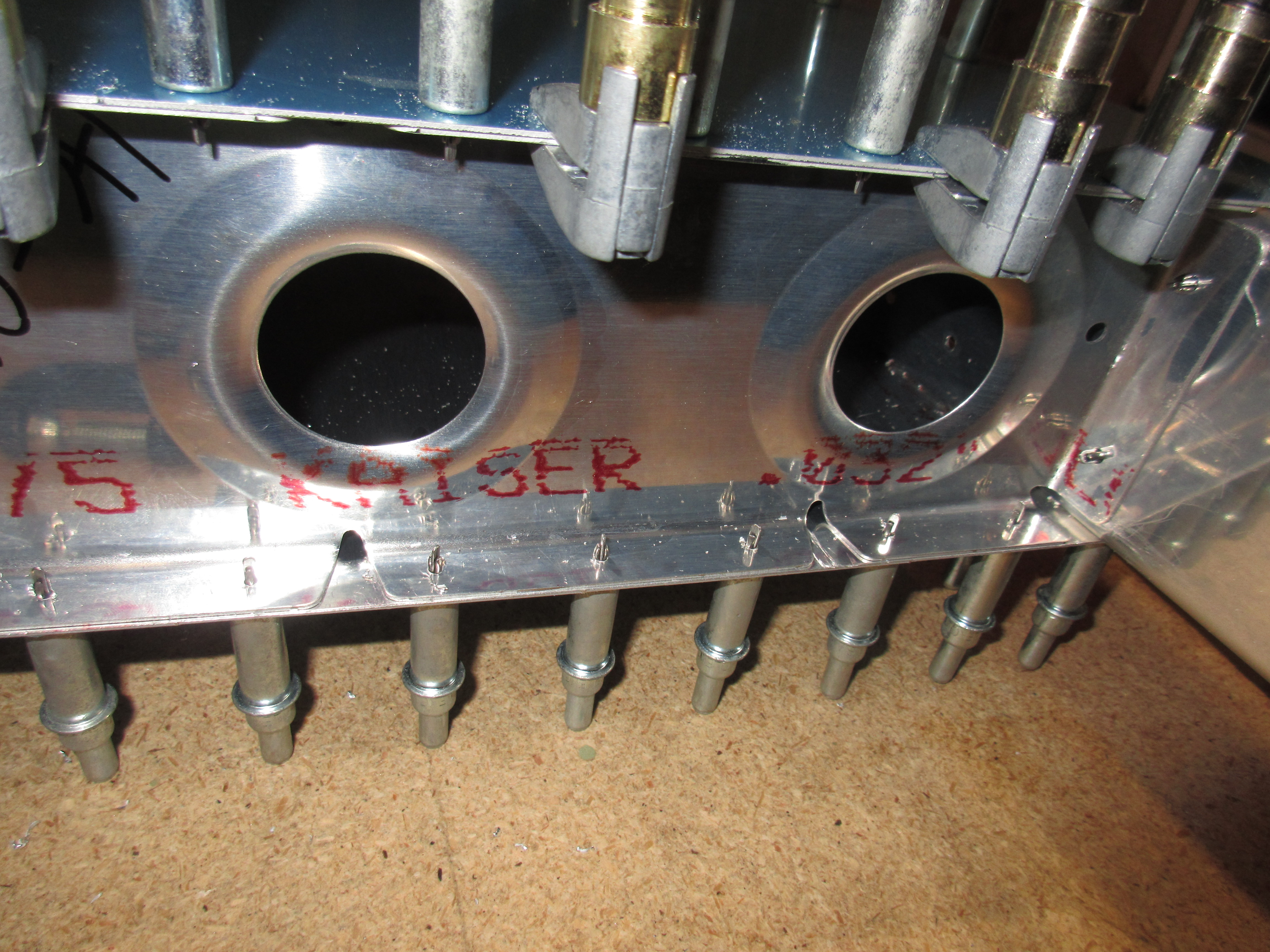
go site I picked out which ribs would be left and right, and marked them. Then I marked the centerlines using the dimensions from the plans for HS-00005 and HS-00006. I finally got to use the Noxon center punch to mark my drill location for HS-00006 and drilled the holes in the front flange.
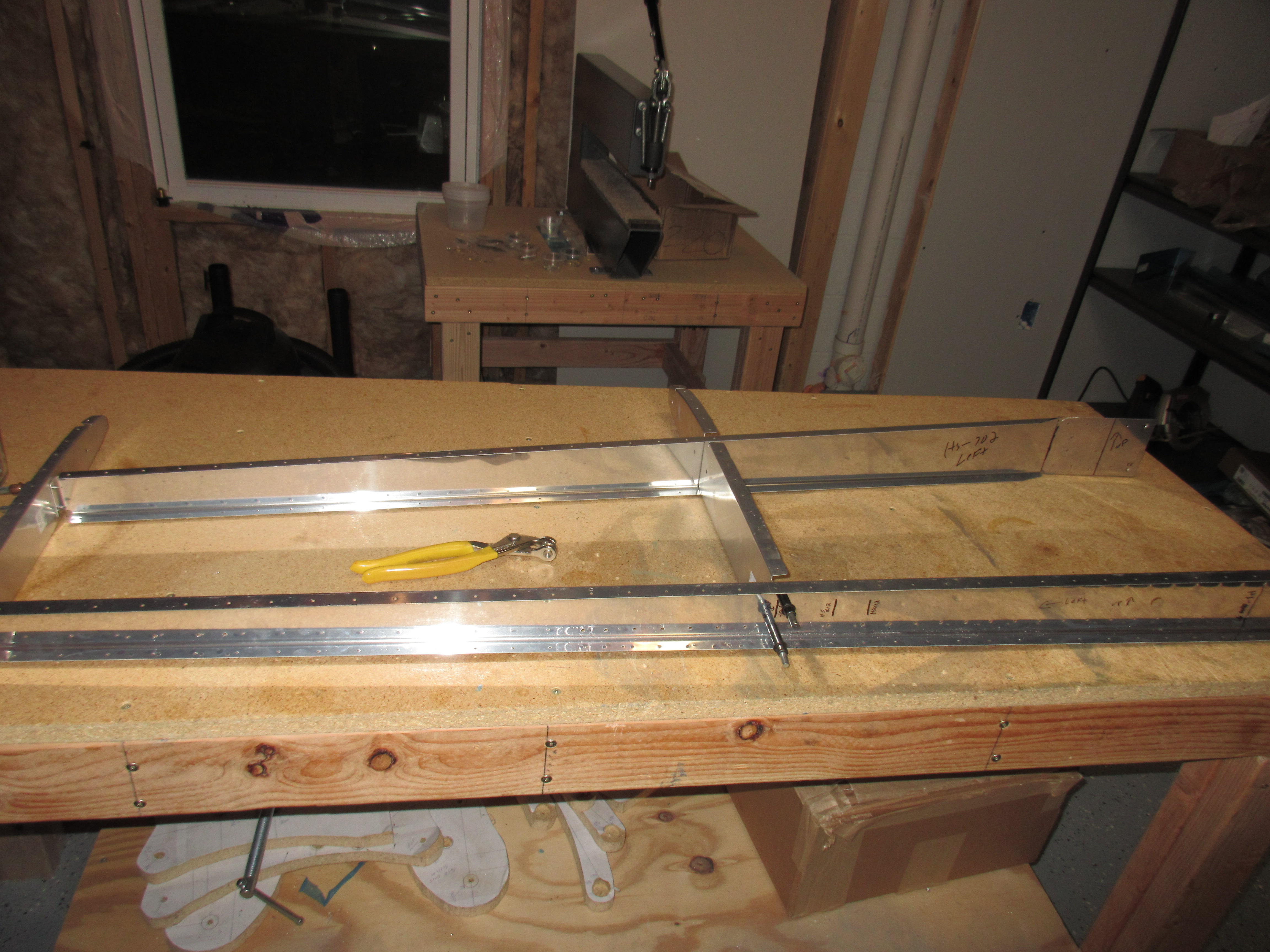
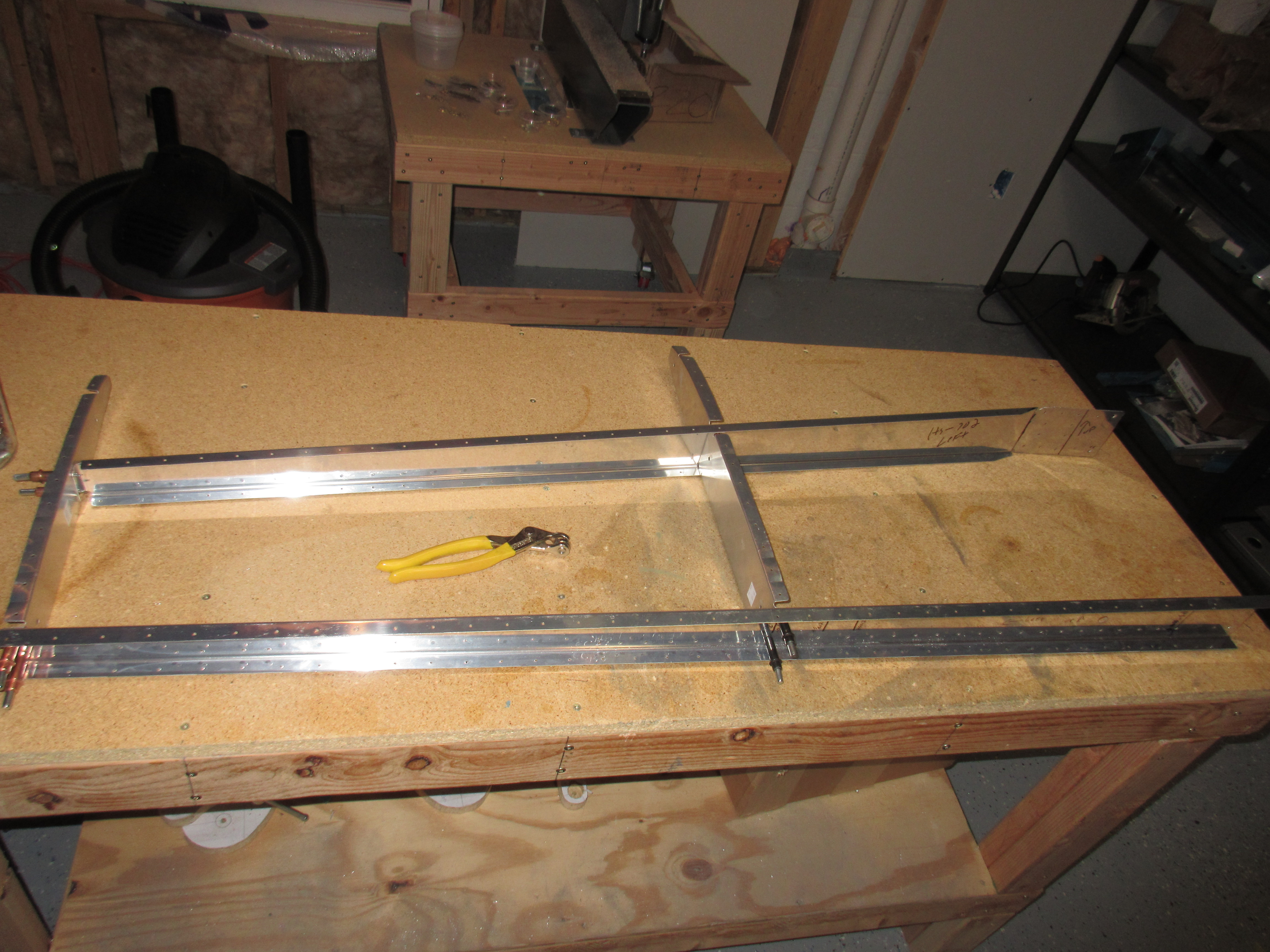
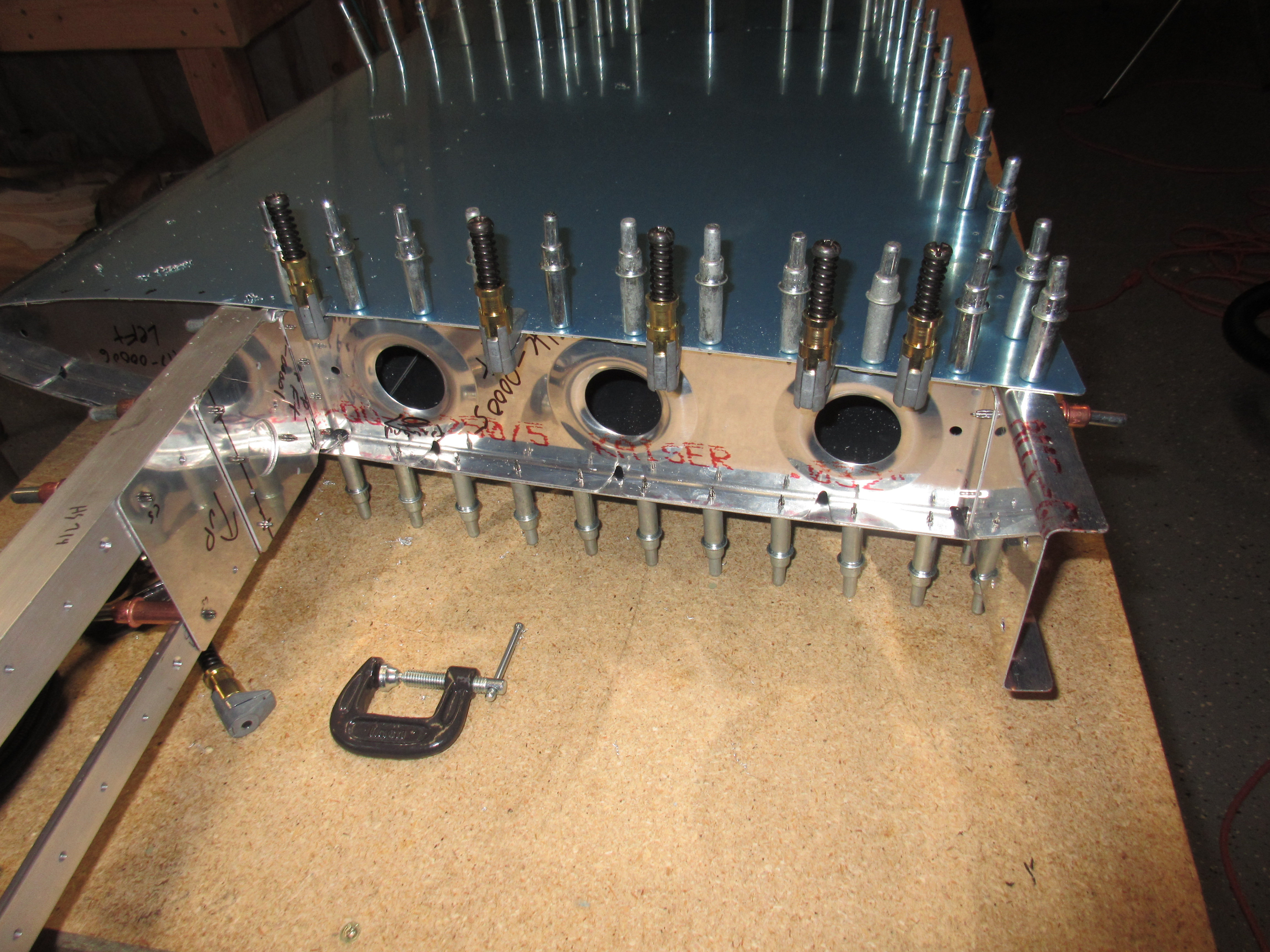
https://anthonynewmancamps.com/tennis-camps/ Starting with the left horizontal stabilizer, I clecoed all the ribs and spars together to form the skeleton. Then I match drilled to #30 all of the holes attaching the ribs to the spars, except for where it attaches to HS-609pp. I left that hole untouched for now per the plans, until later on then drilled it to size#21. The un-clecod everything to clean out the drill chips. The pneumatic cleco tool make this work easy.
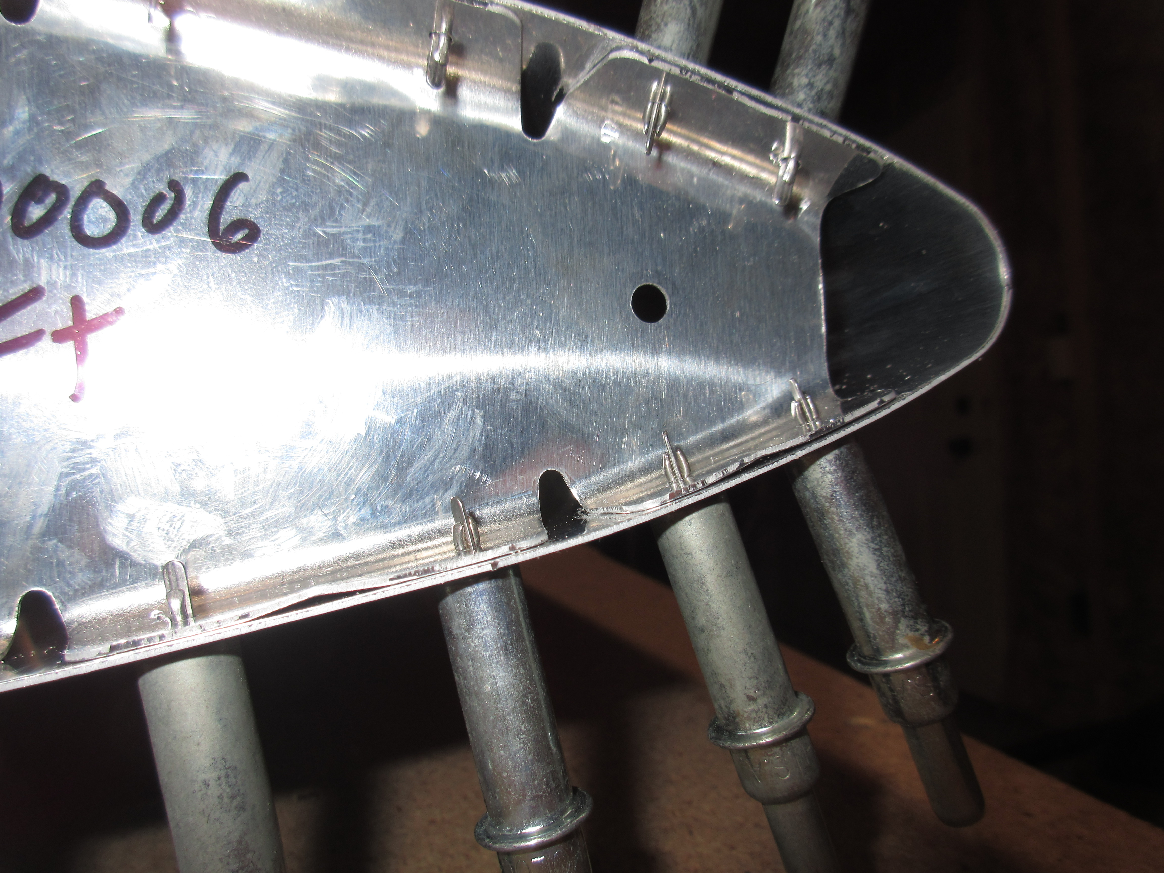
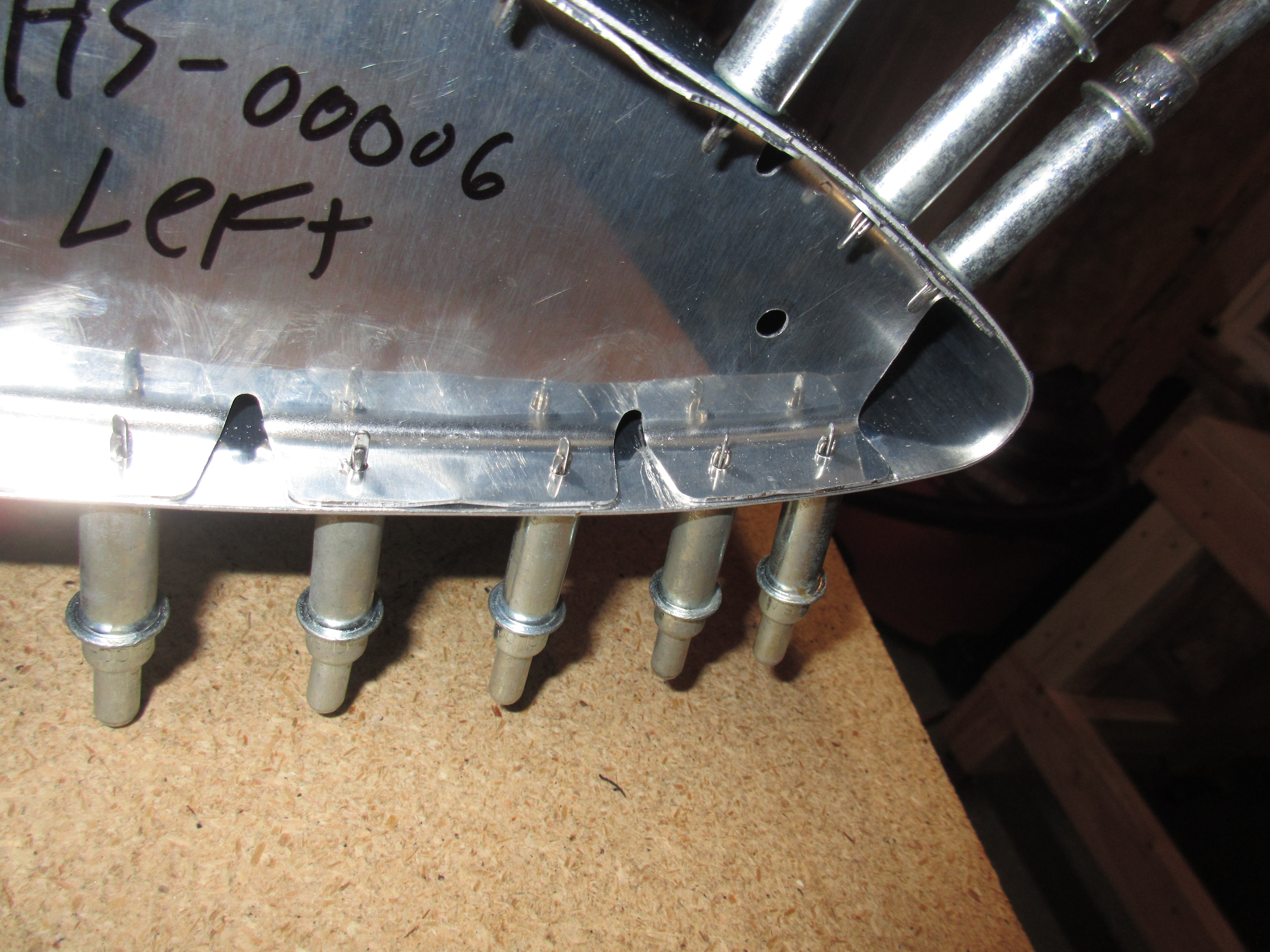
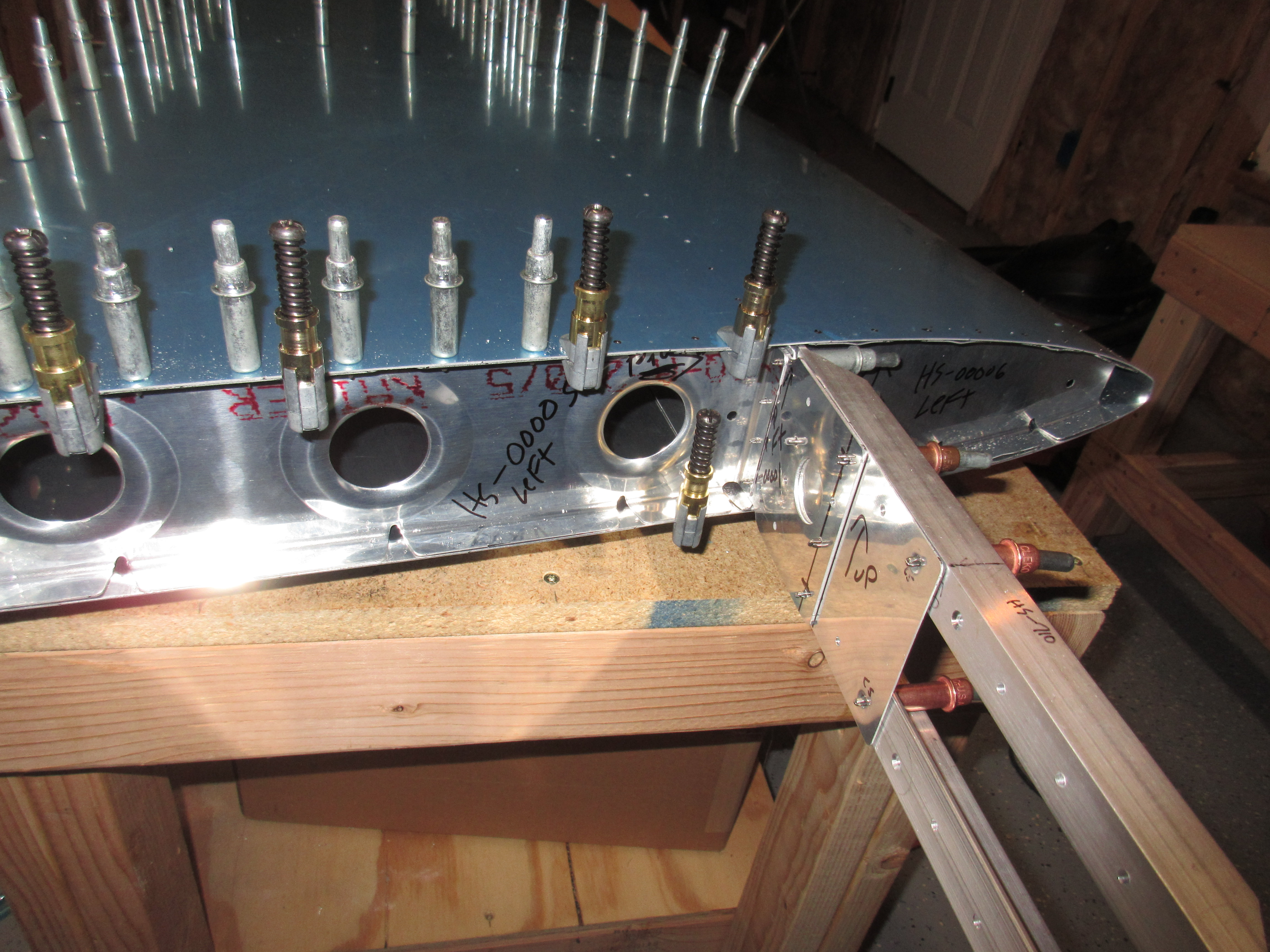
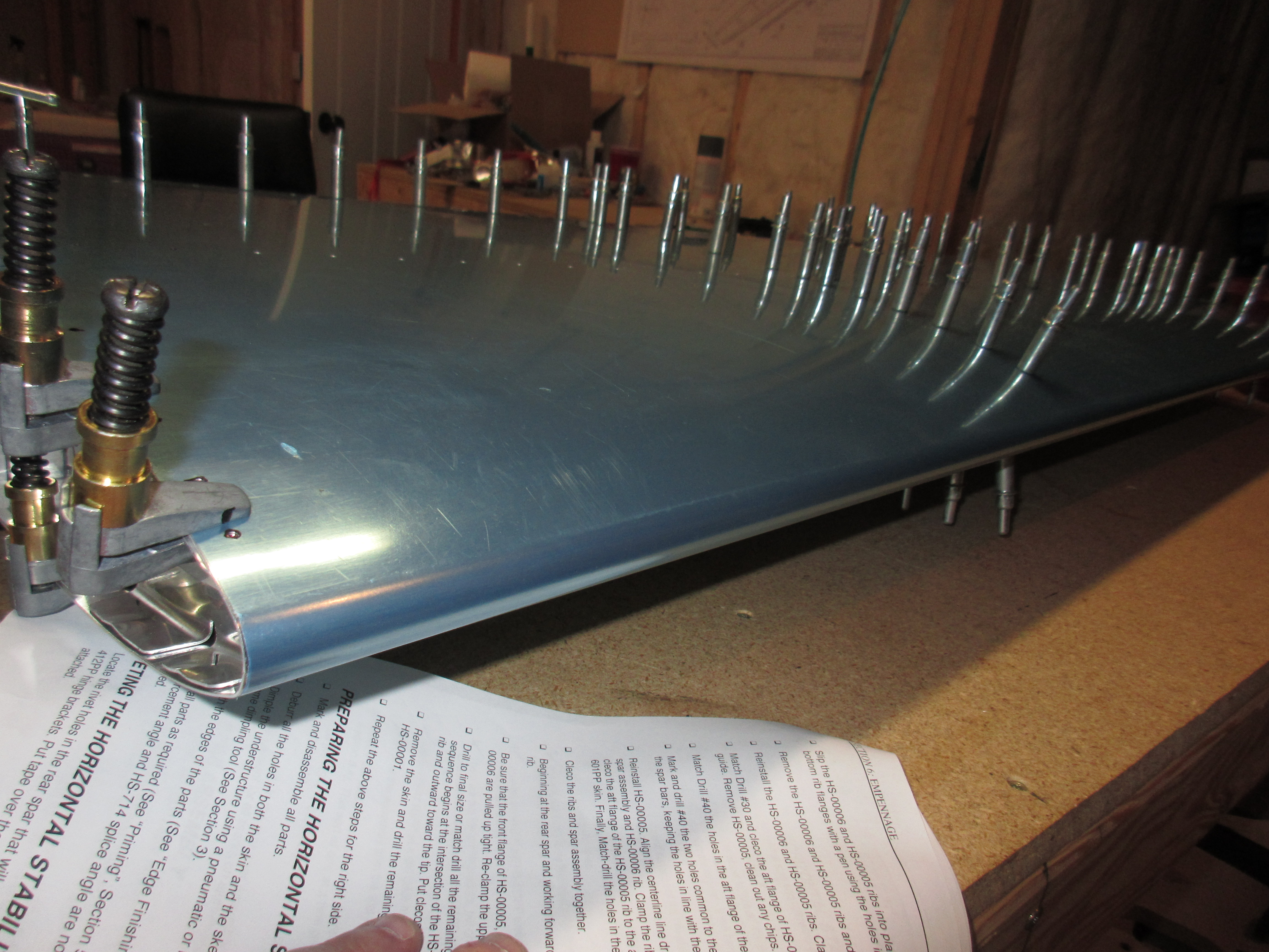
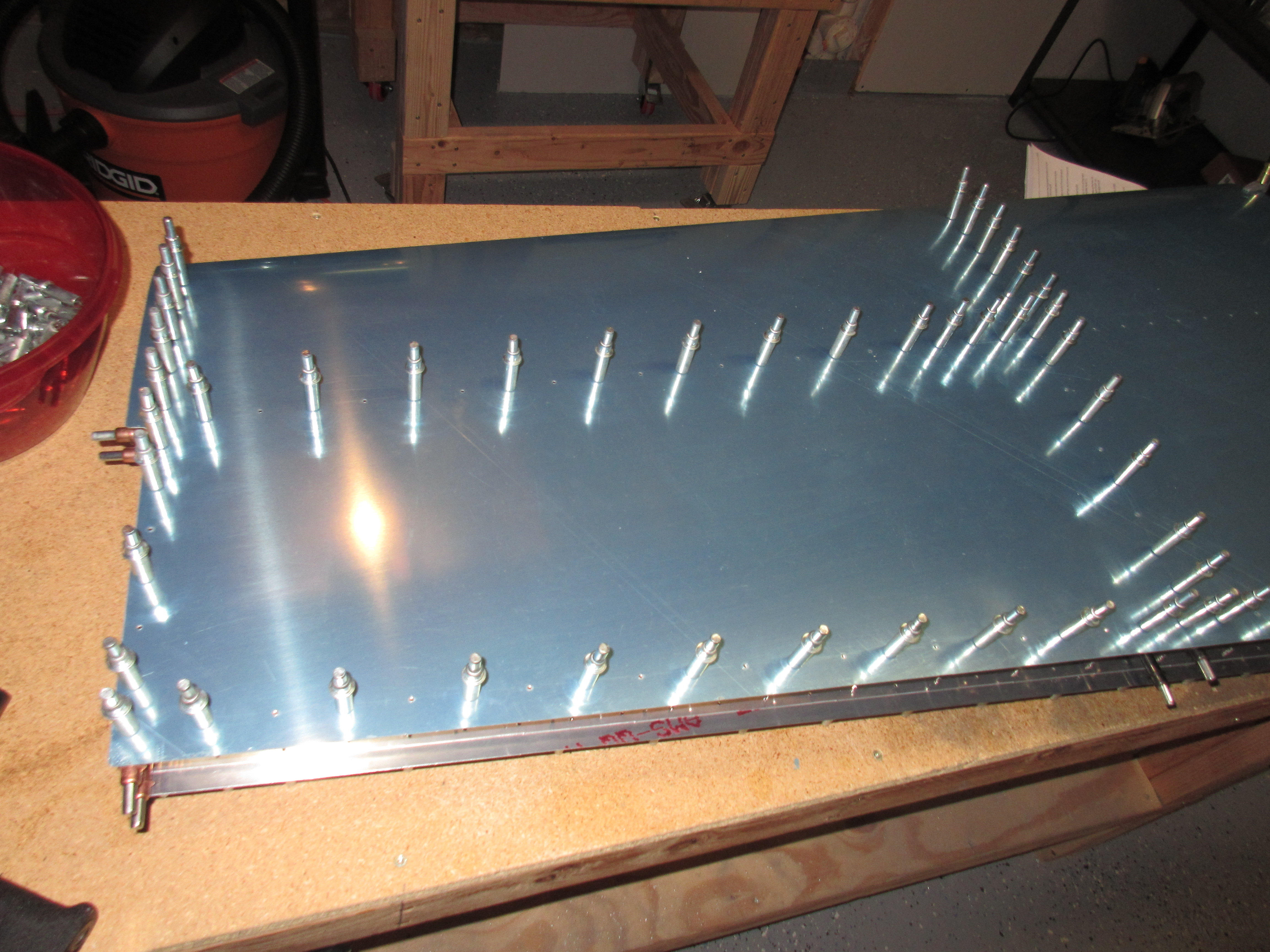
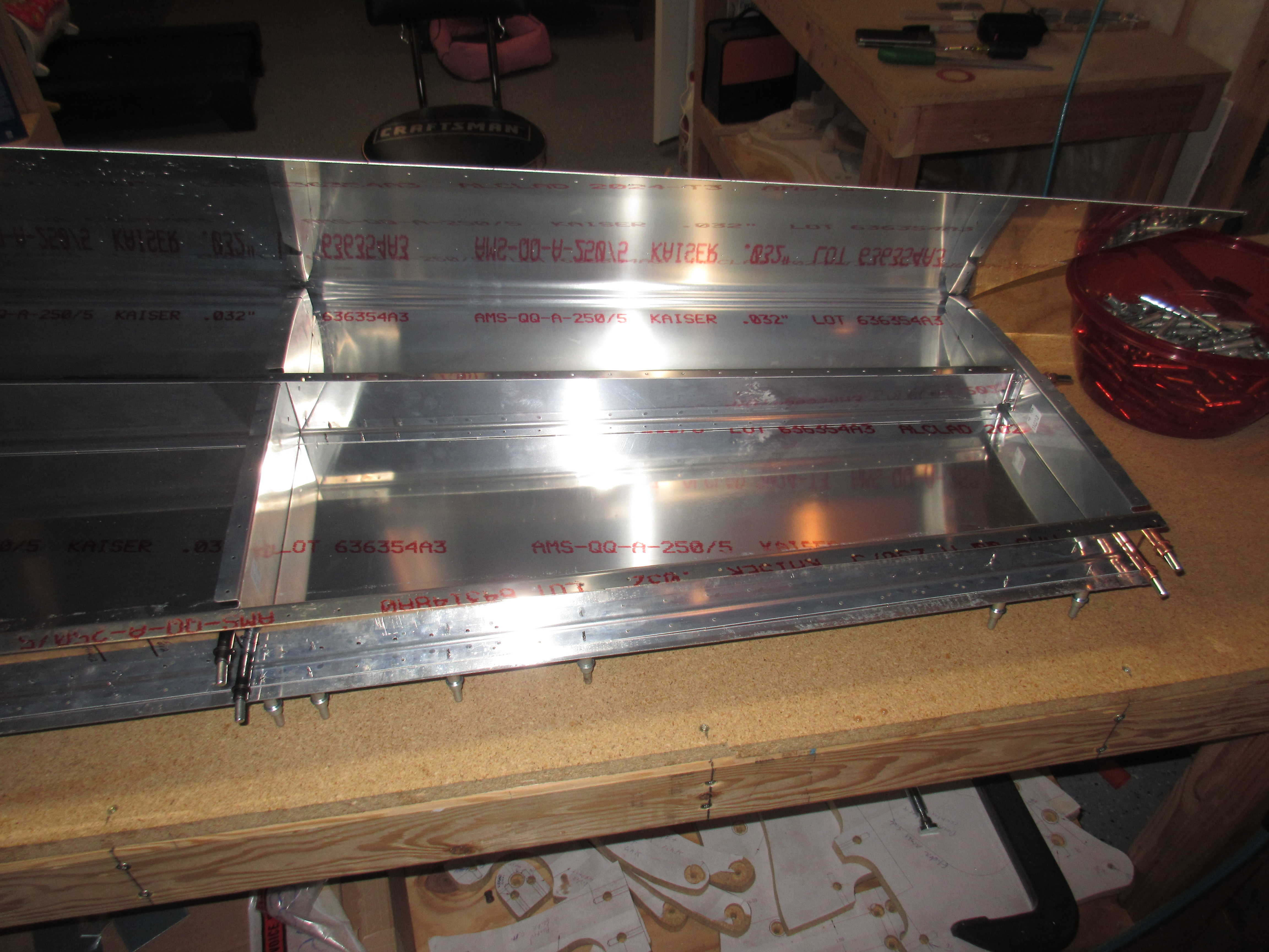
Zolpidem 5Mg Order Online After re-assembling the left skeleton, I had my wife help me get the HS-601PP skin clecod to the skeleton. This took some finesse. Due to the gradual taper on the leading edge, we had to very gently flex the skin to fit around the nose ribs without bending them. After a few attempts, we managed to get the skin clecod down and looking like an airplane part!
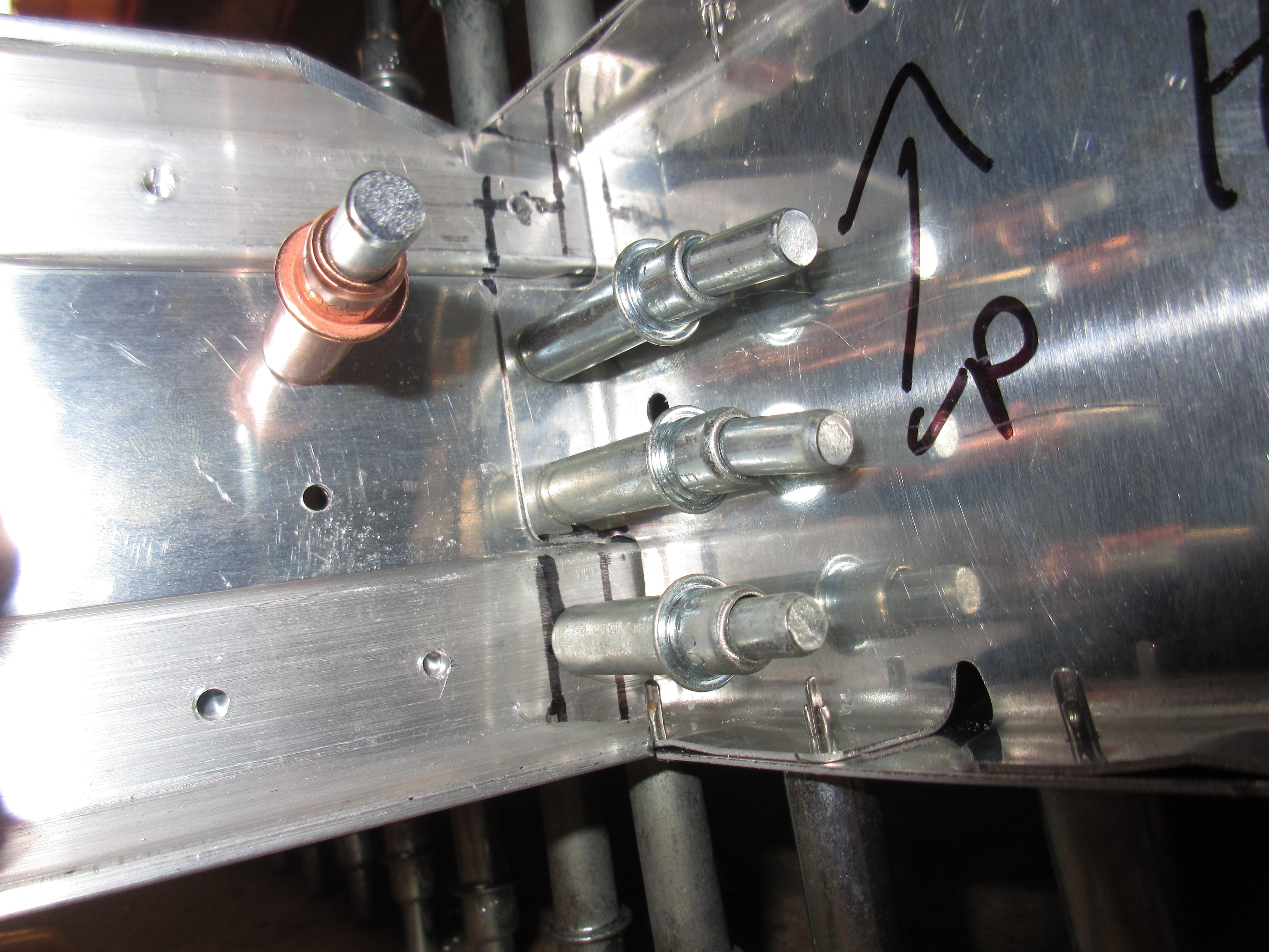
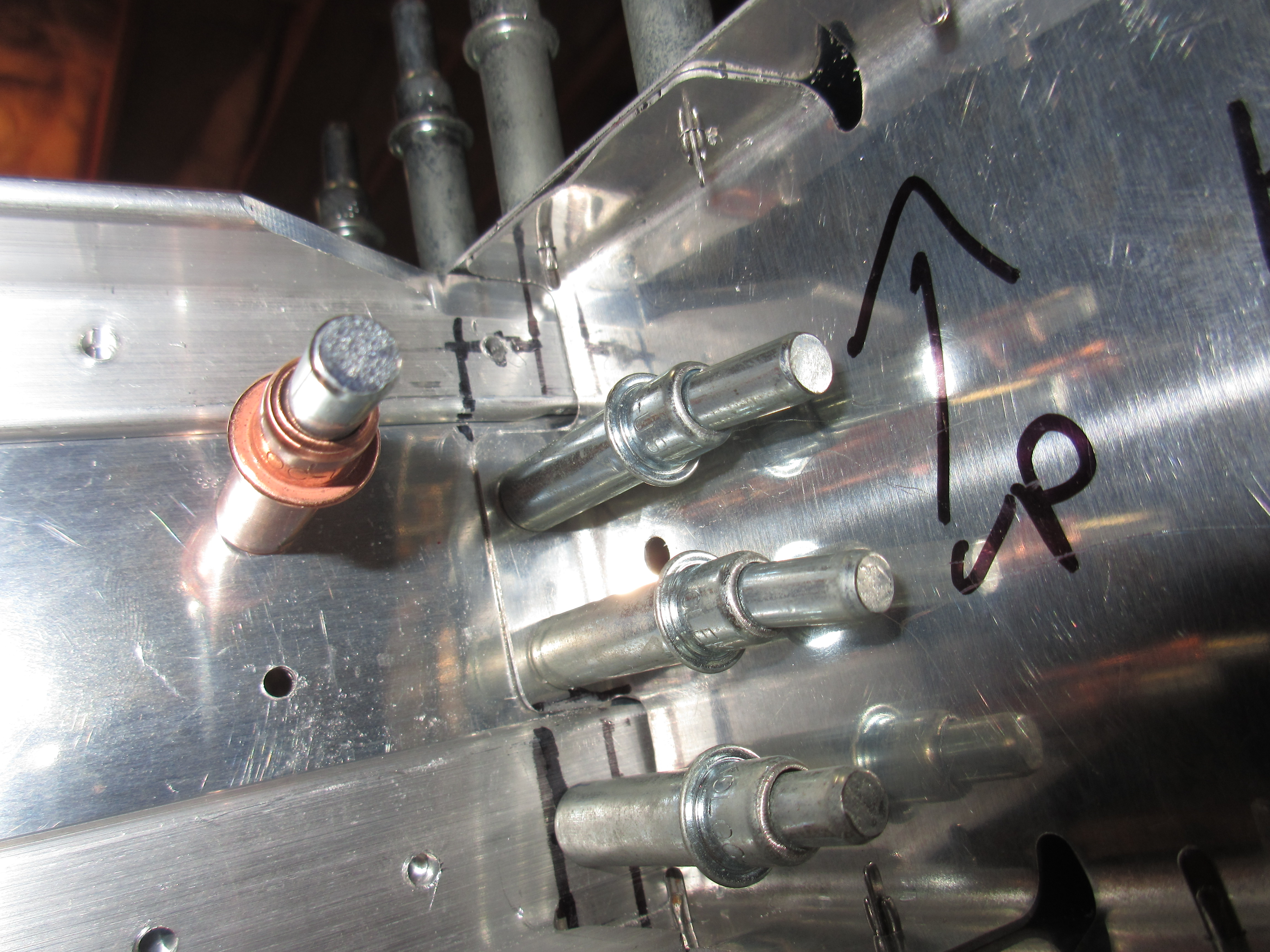
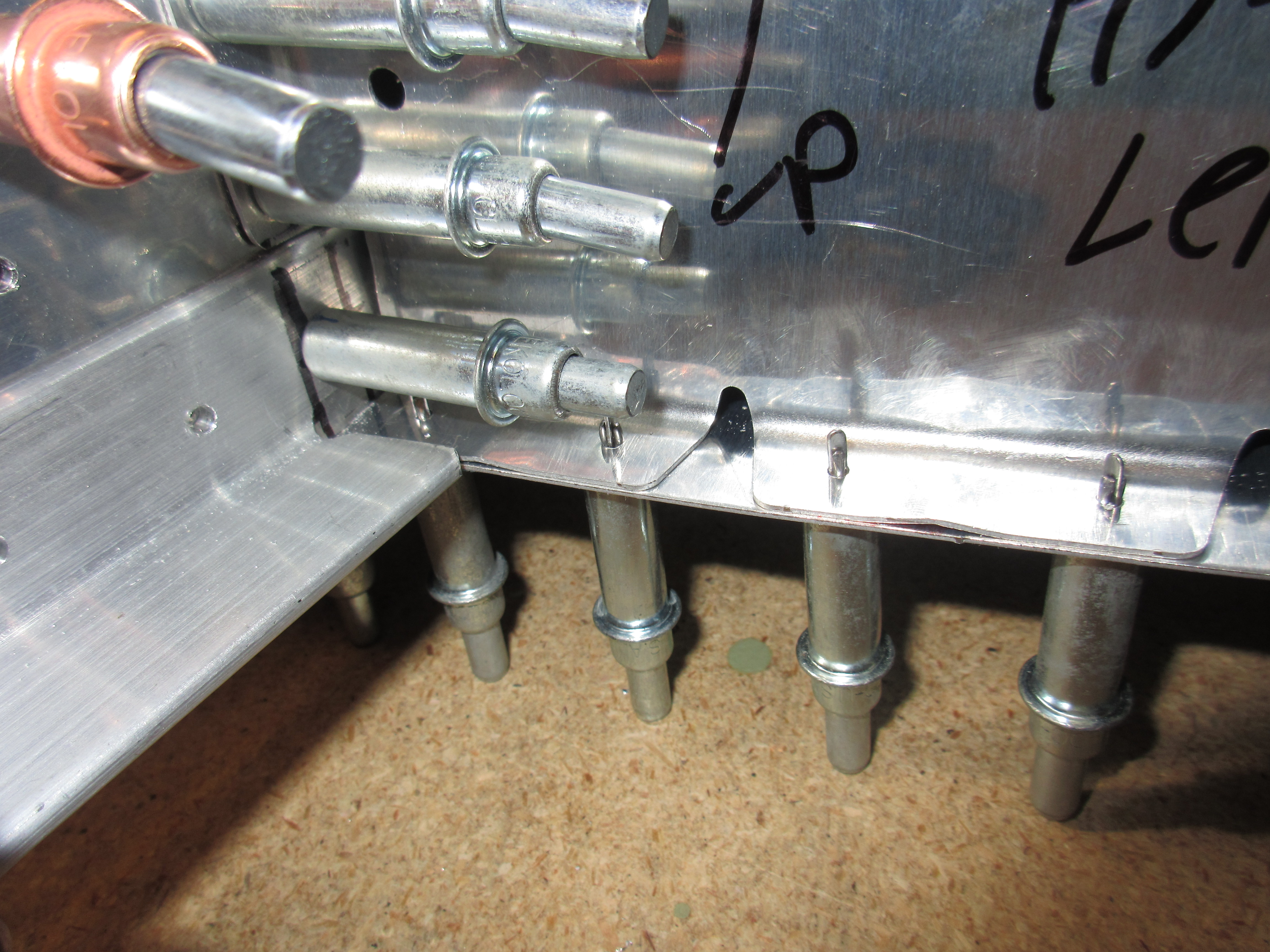
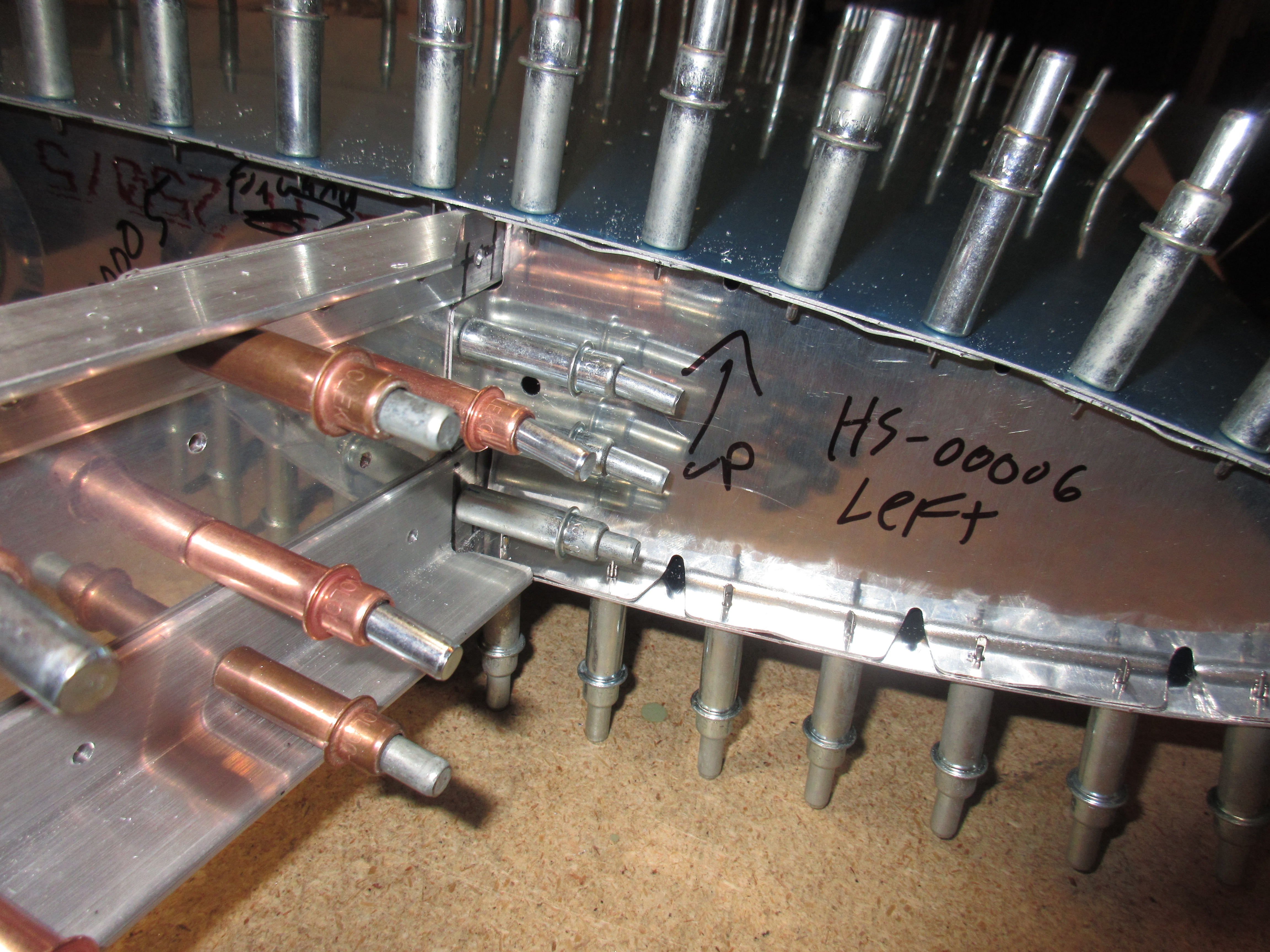
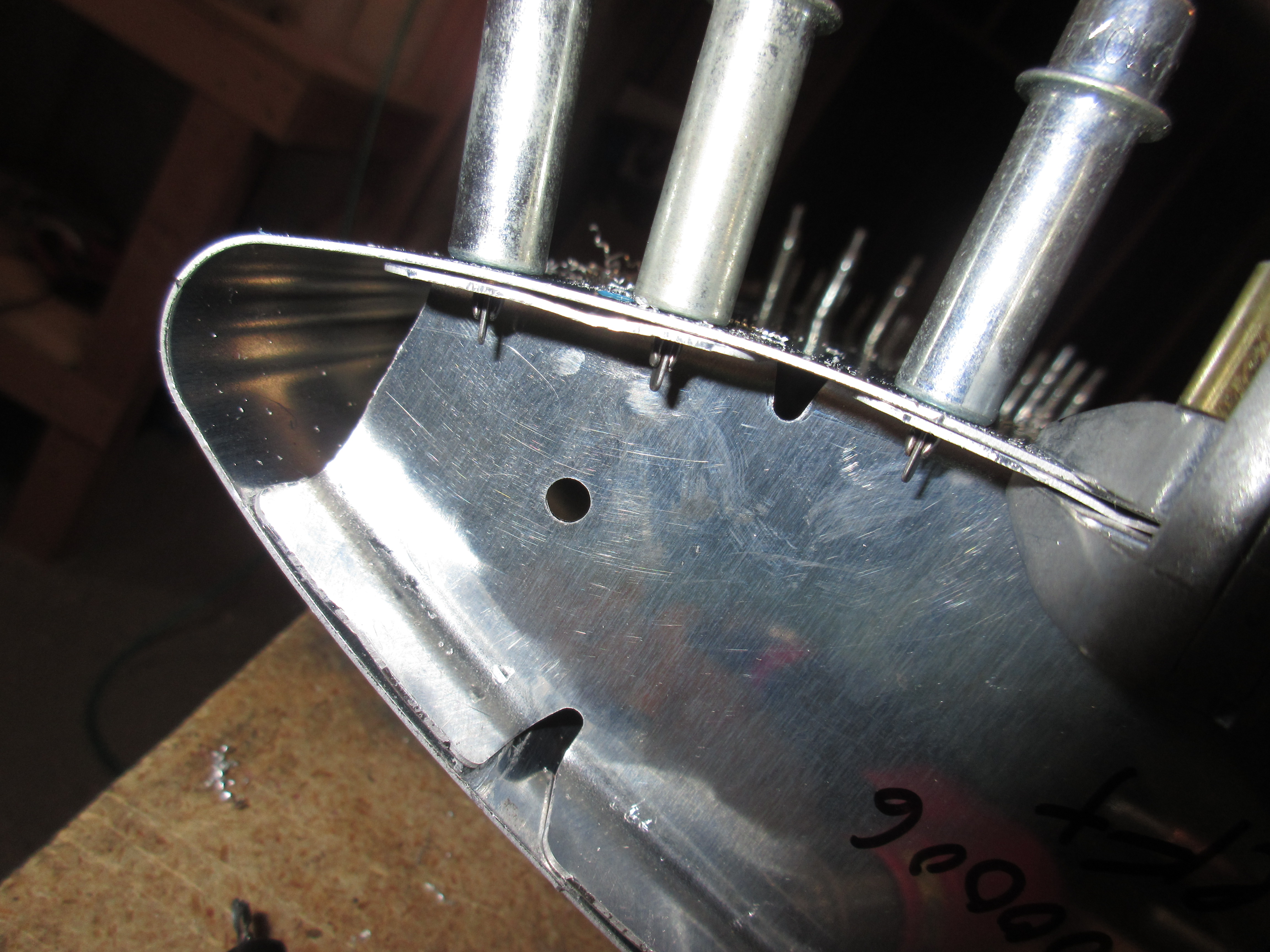
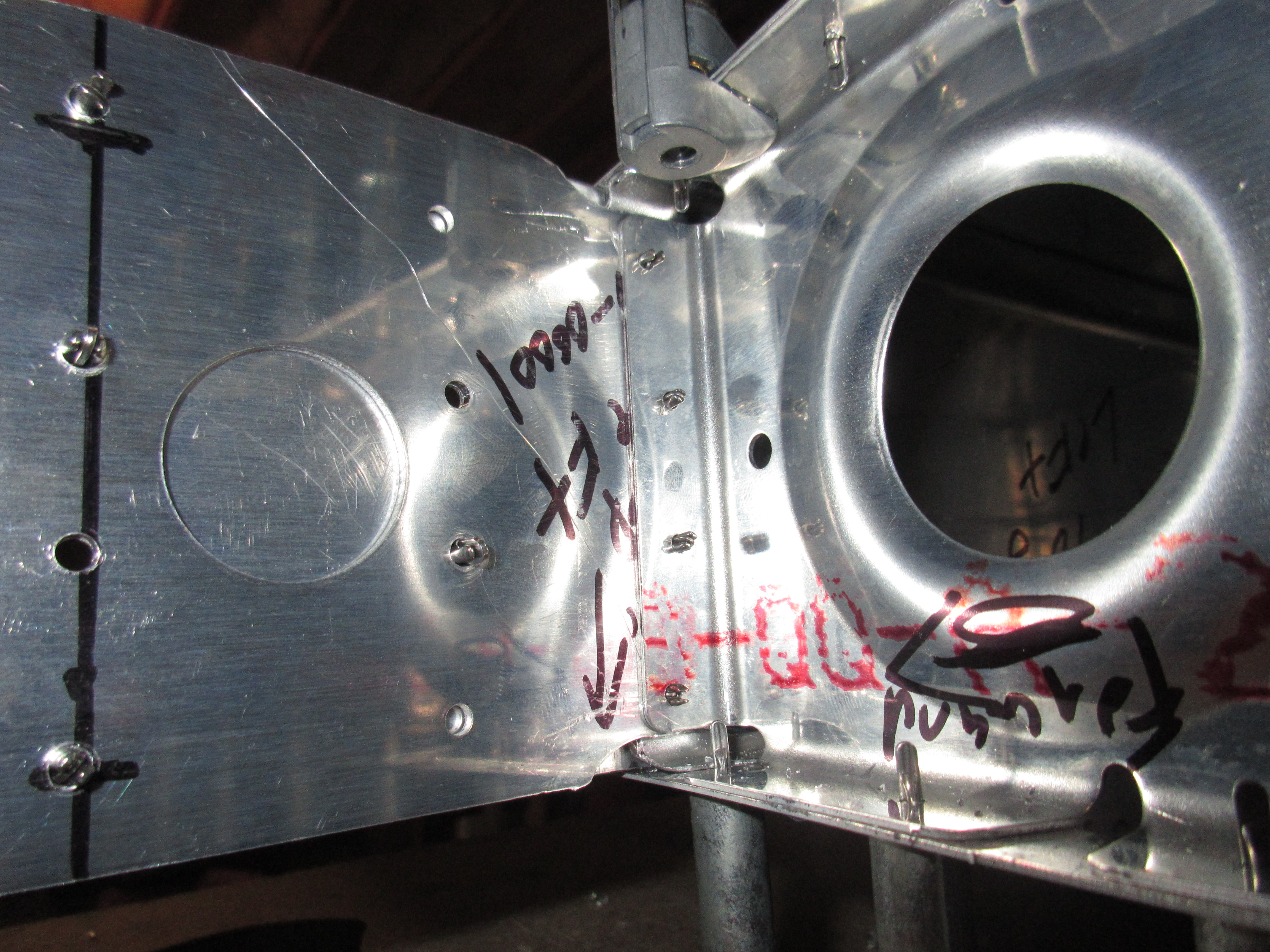
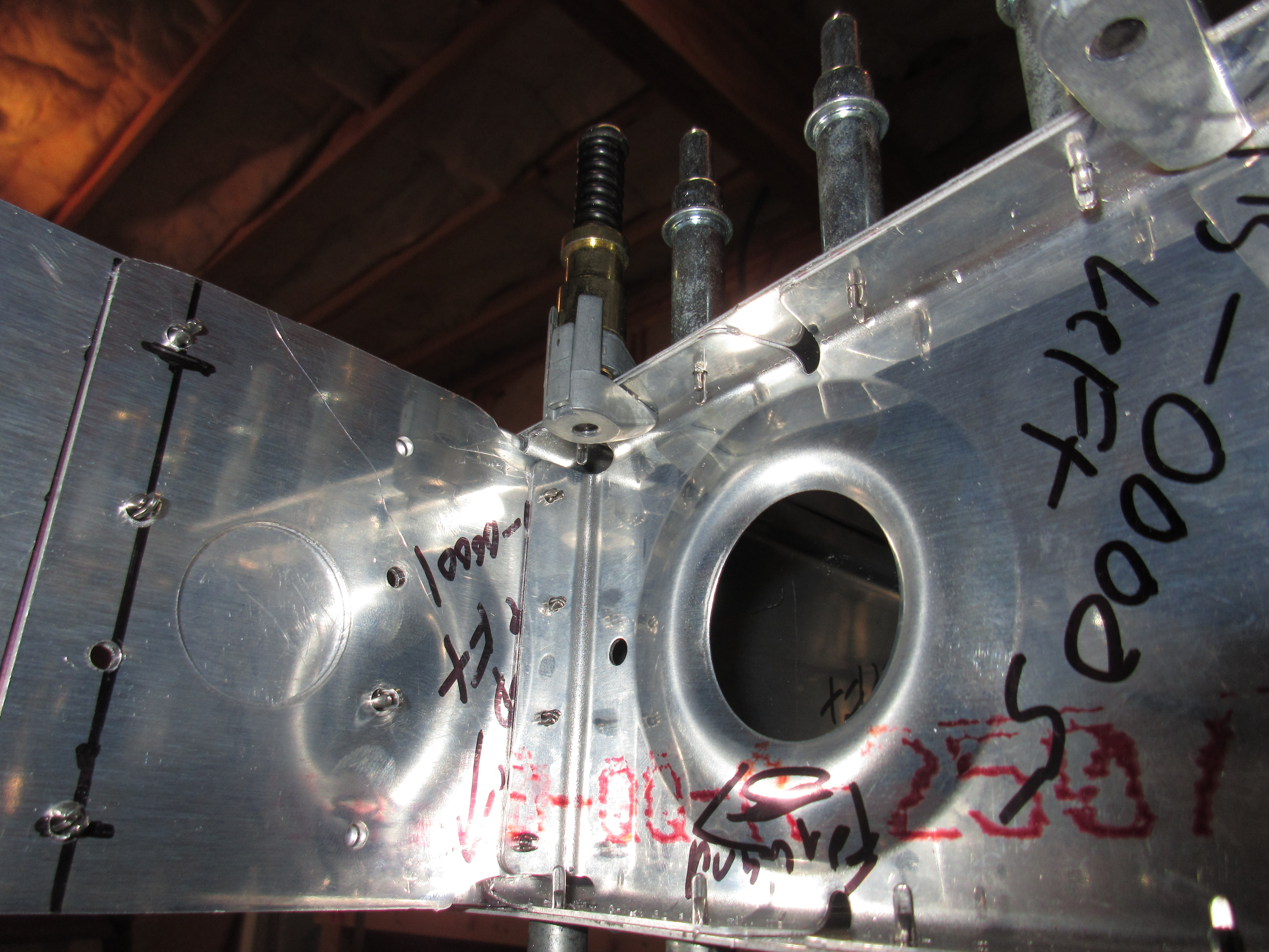
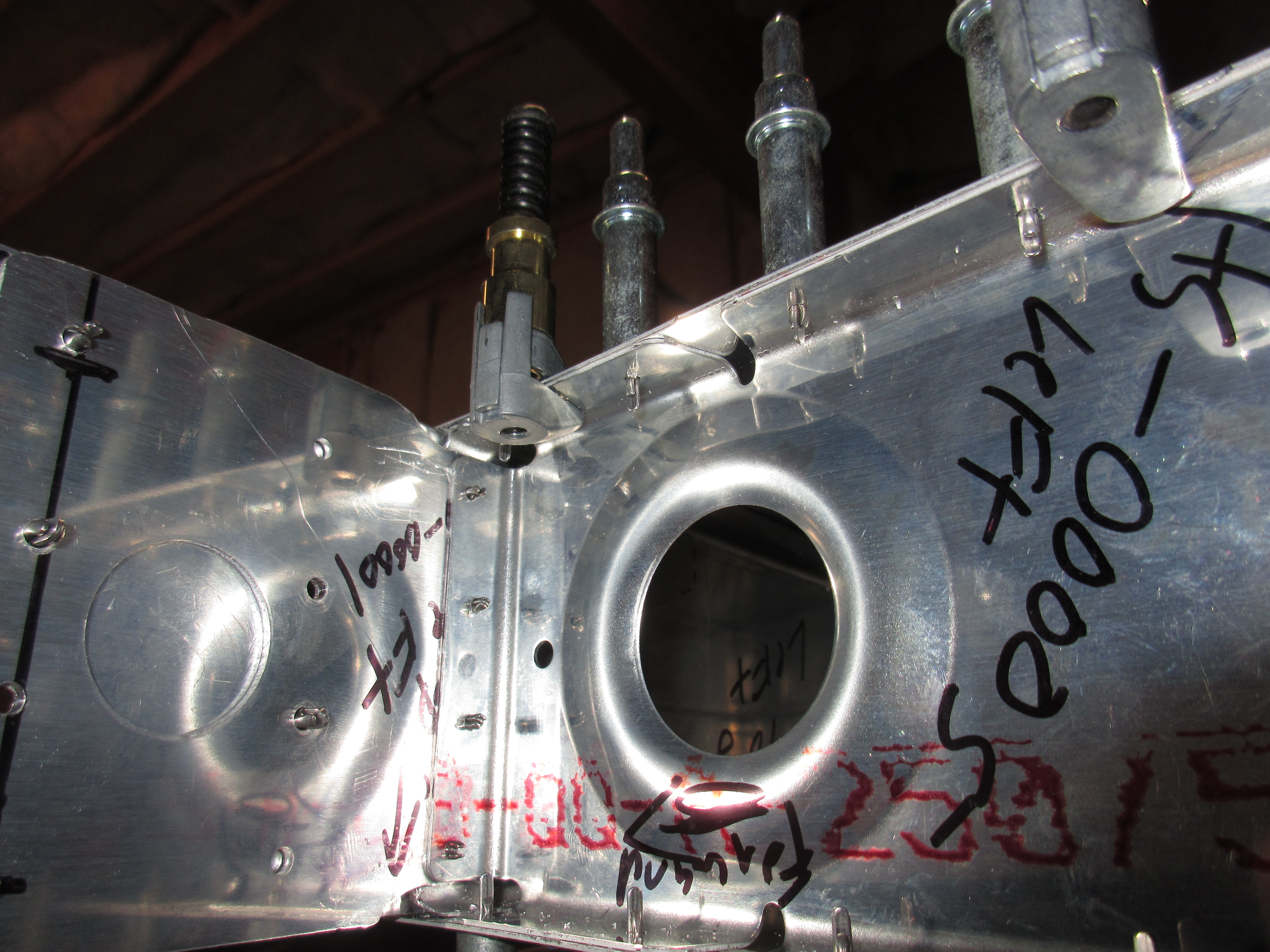
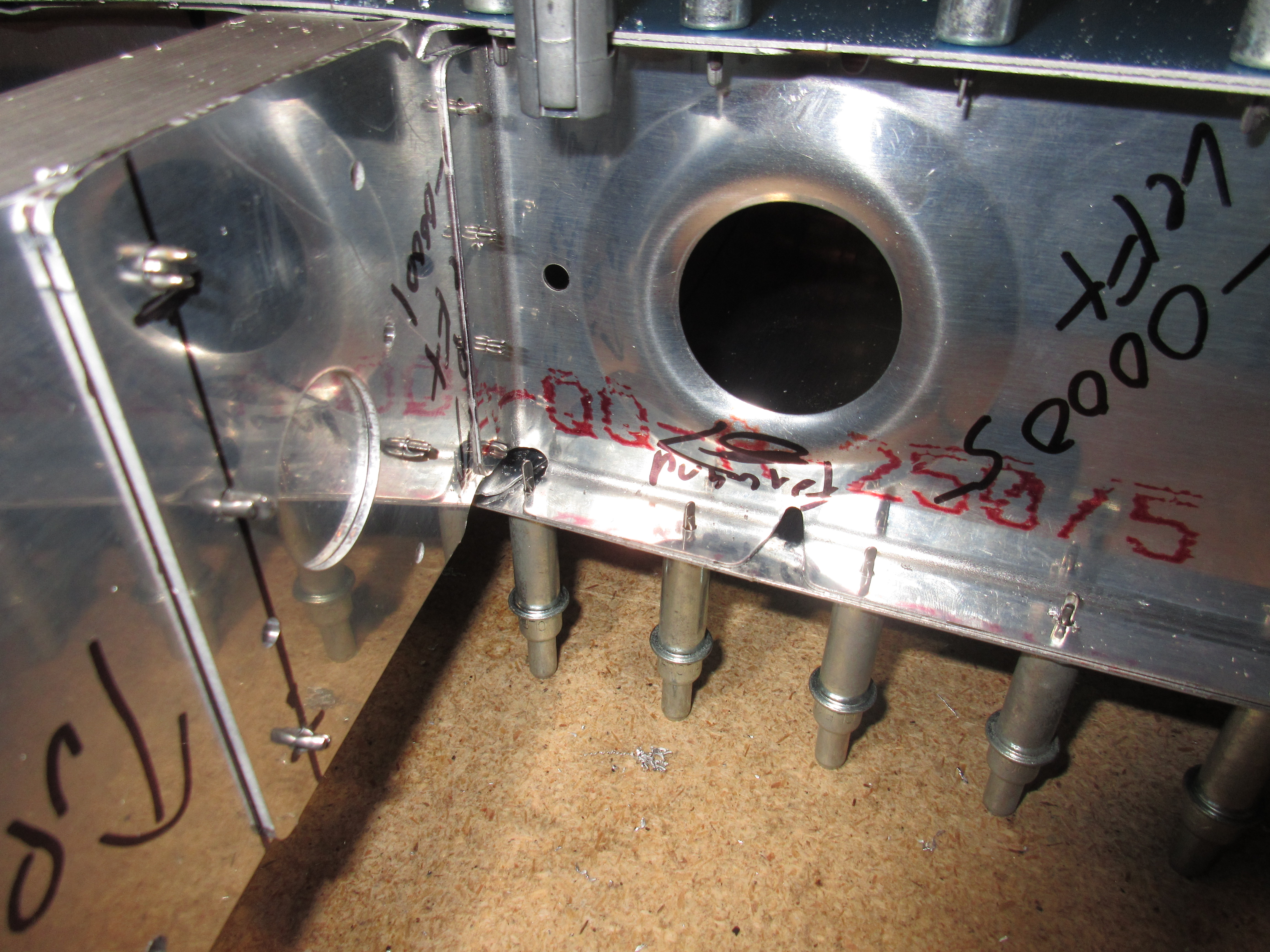
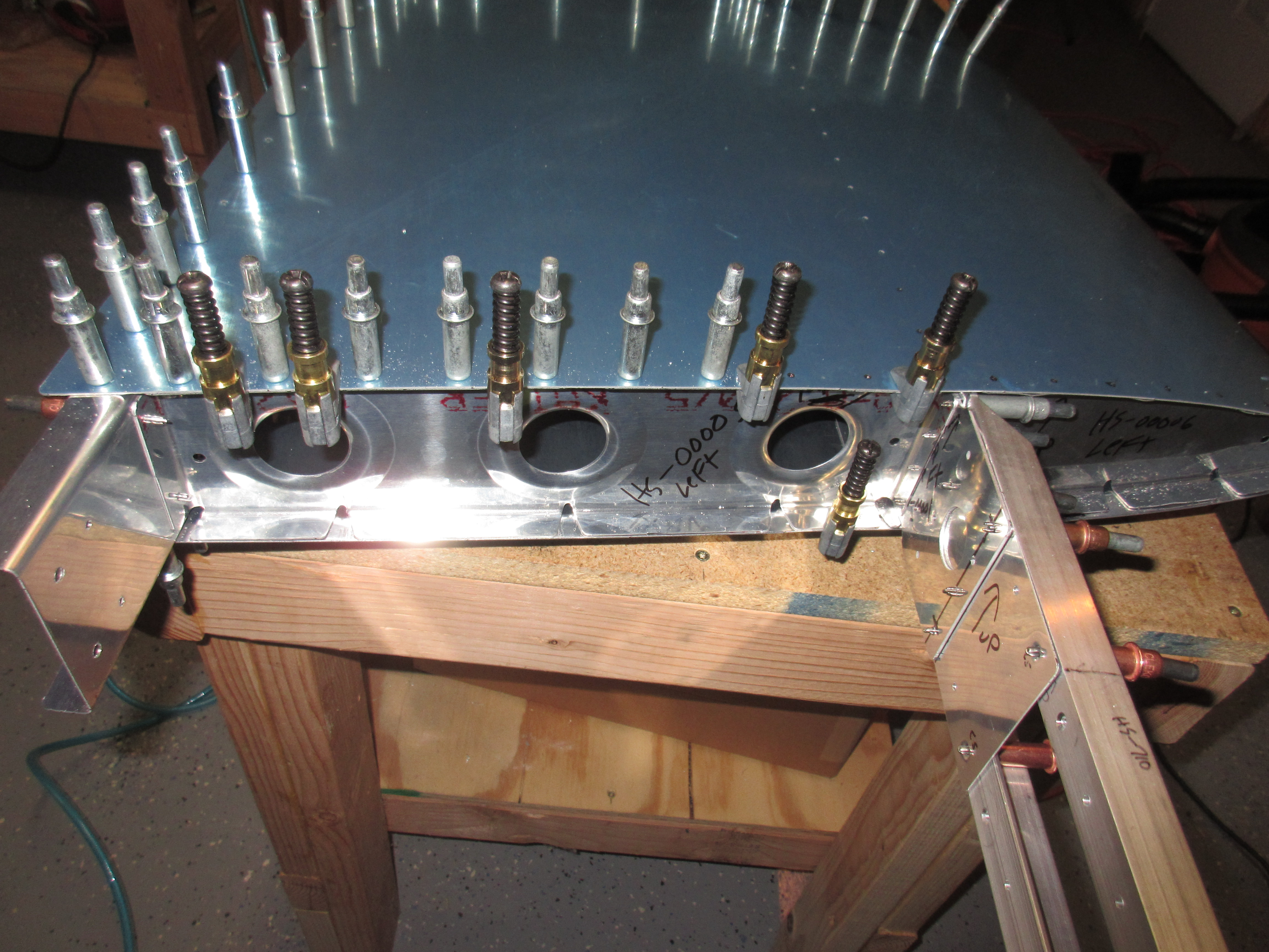
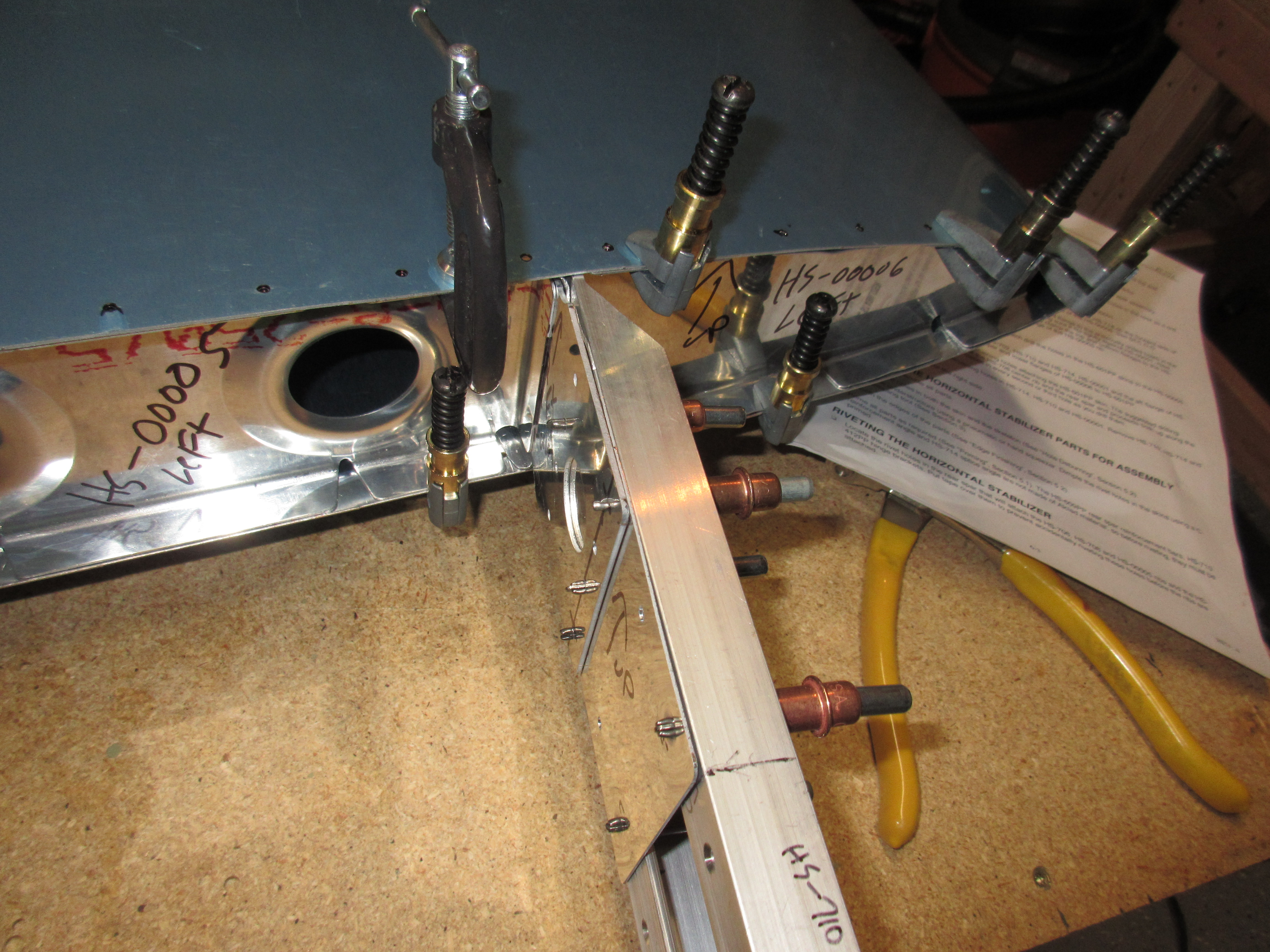
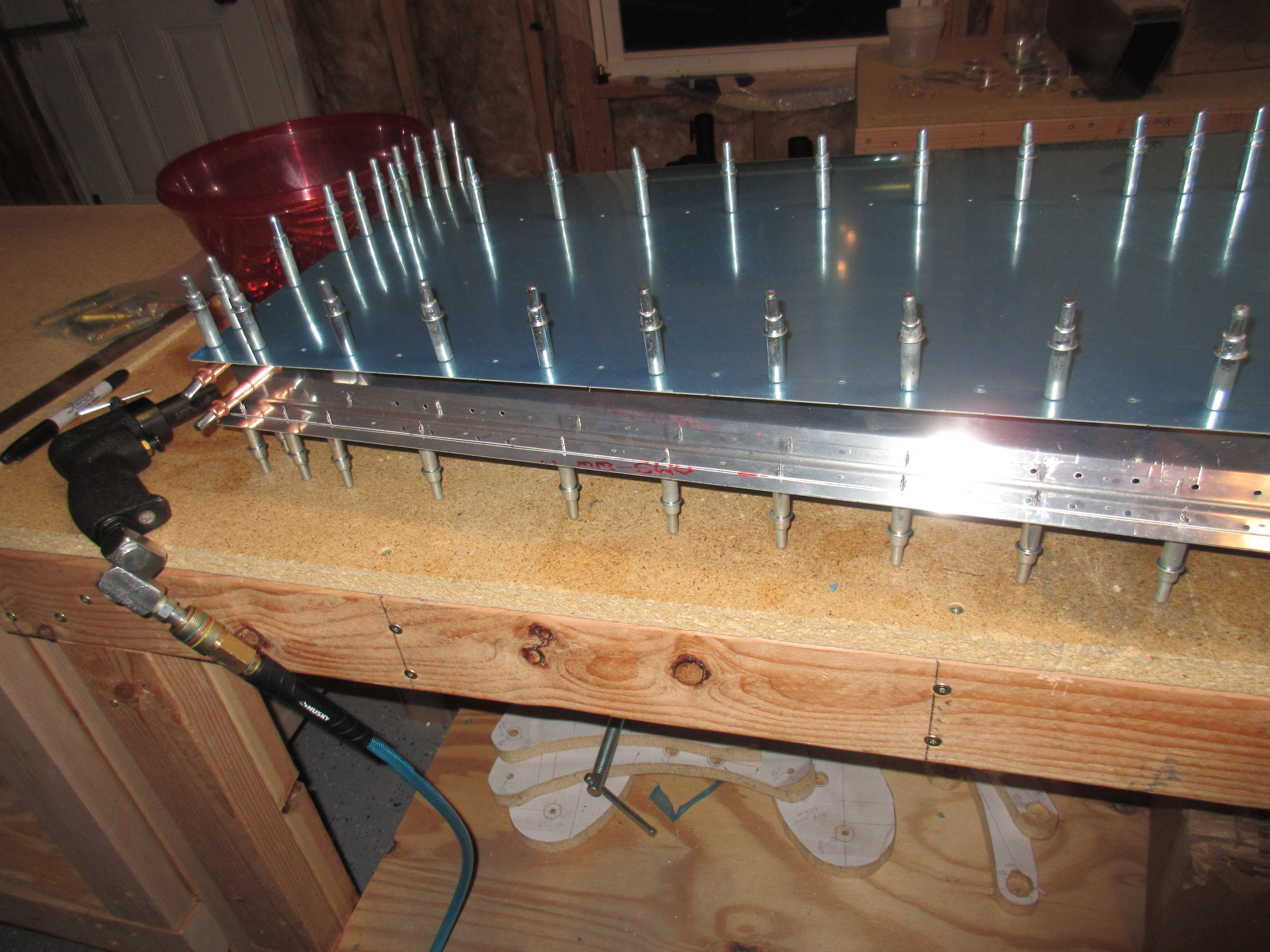
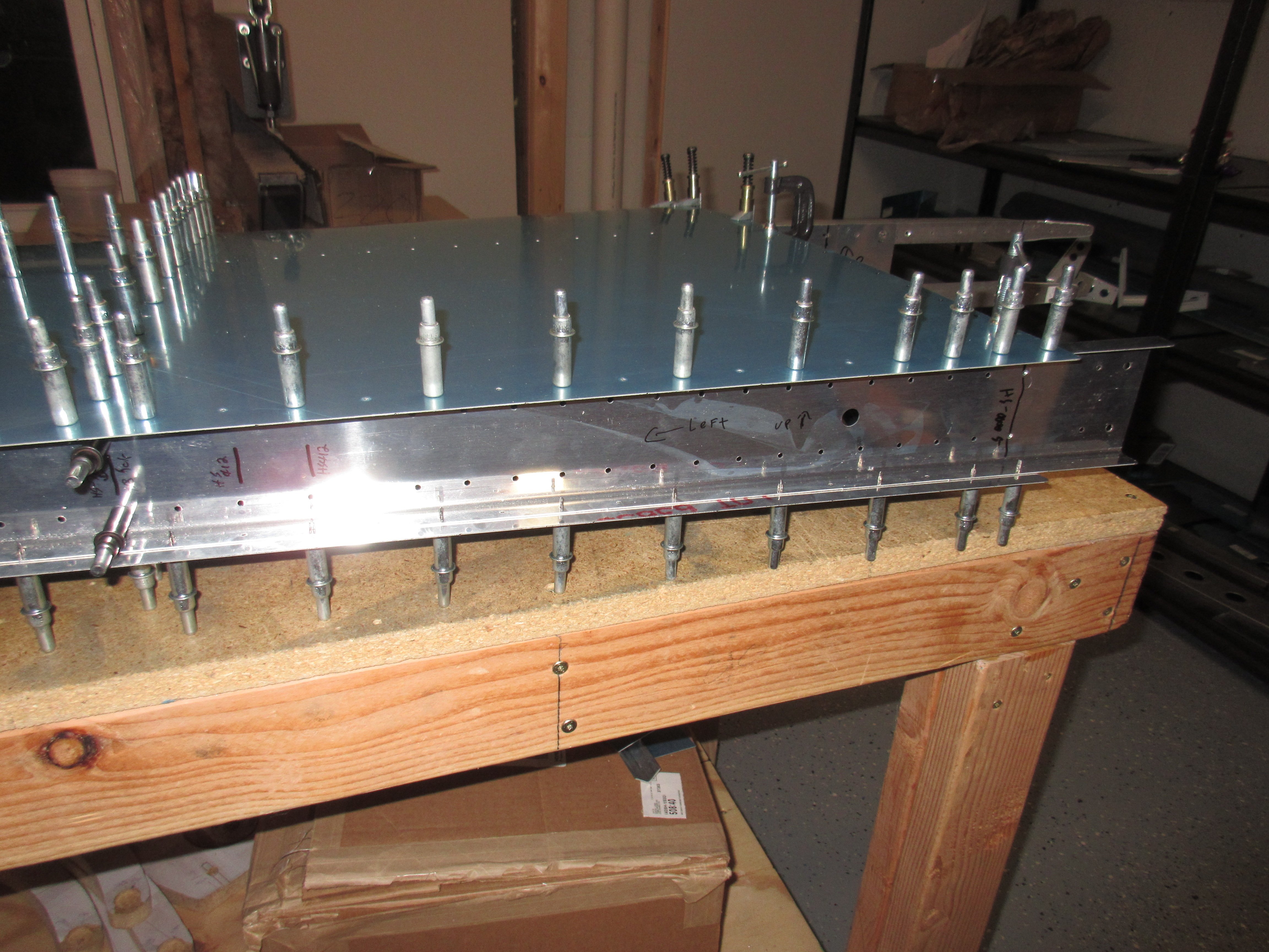
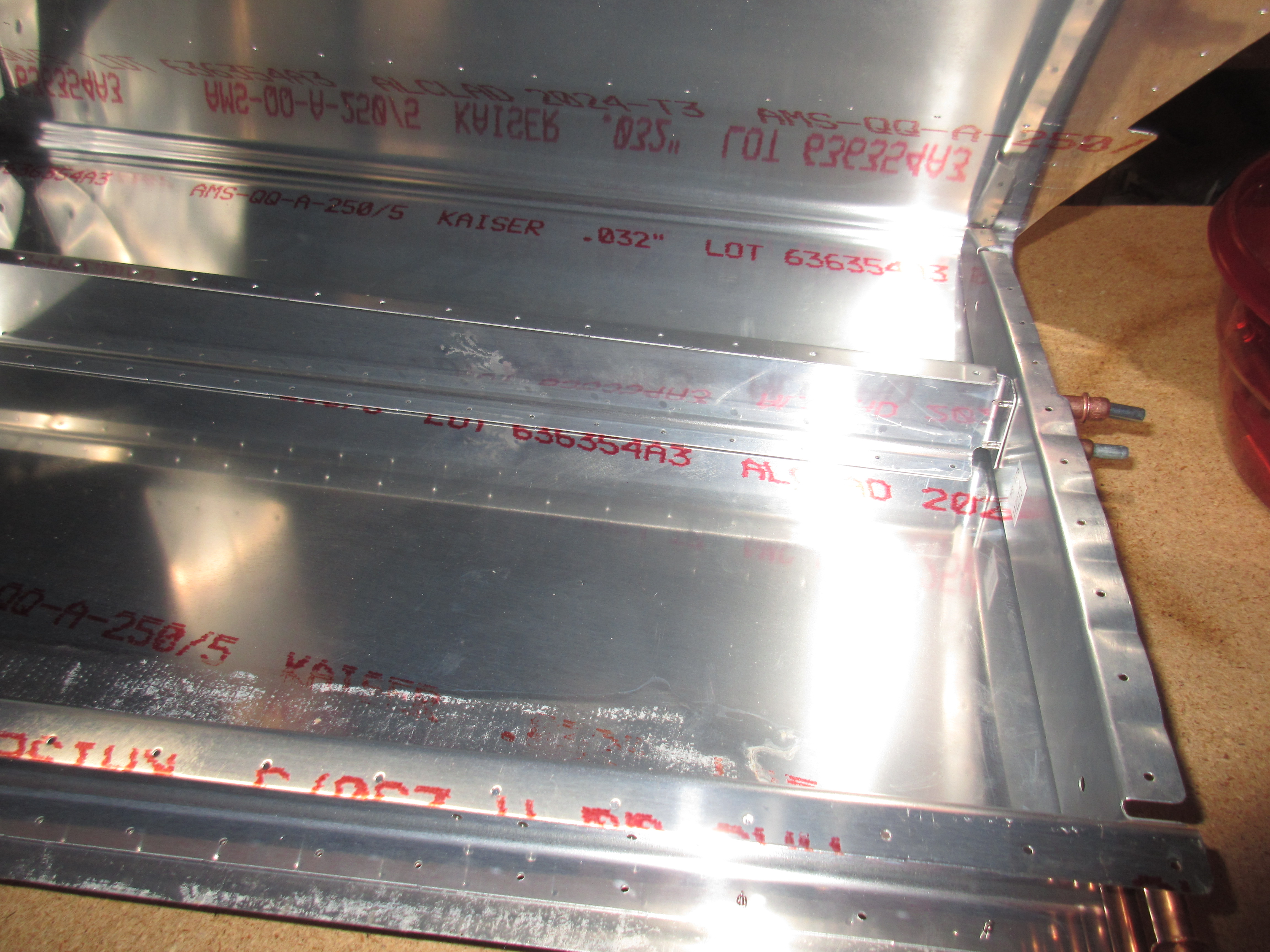
source site Then it was time to fit, clamp and drill the HS-00005 and HS-00006 ribs. This took me a good bit of fiddling around. This started with fitting the HS-00001 doubler, and the HS-710 and HS-714 support bars to the front spar. Then I inserted the ribs and worked to get them lined up perfectly with the edge of the skins. These parts are not pre-punched so I marked a centerline across all the flanges just to make sure I lined them up to maintain edge distance on the skins holes. I used the front rib holes to back drill the front spar after I had it lined up with the skin, and then removed it so I could insert the rear rib (HS-00005) and line up the centerline mark through the holes I just drilled, then back drill it. After all the aligning and clamping and measuring, I ended up with the front and rear ribs completely flush against the edge of the skin, with the centerlines lined up on the skins holes. After everything was clamped and held securely in place, I began back drilling the HS-00005 rib using the holes in the skin, and then followed up with the HS-00006 rib in the same manner.
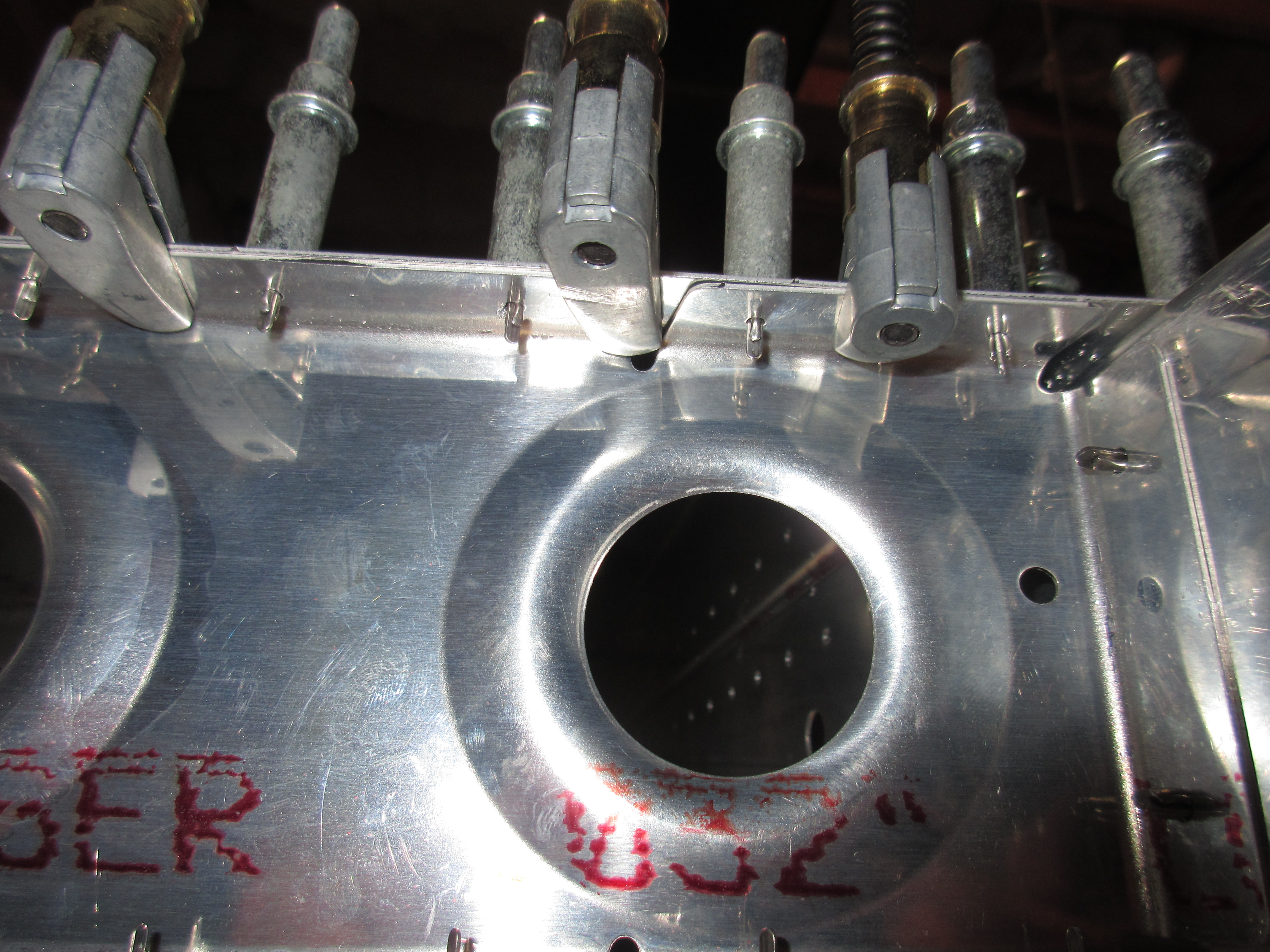
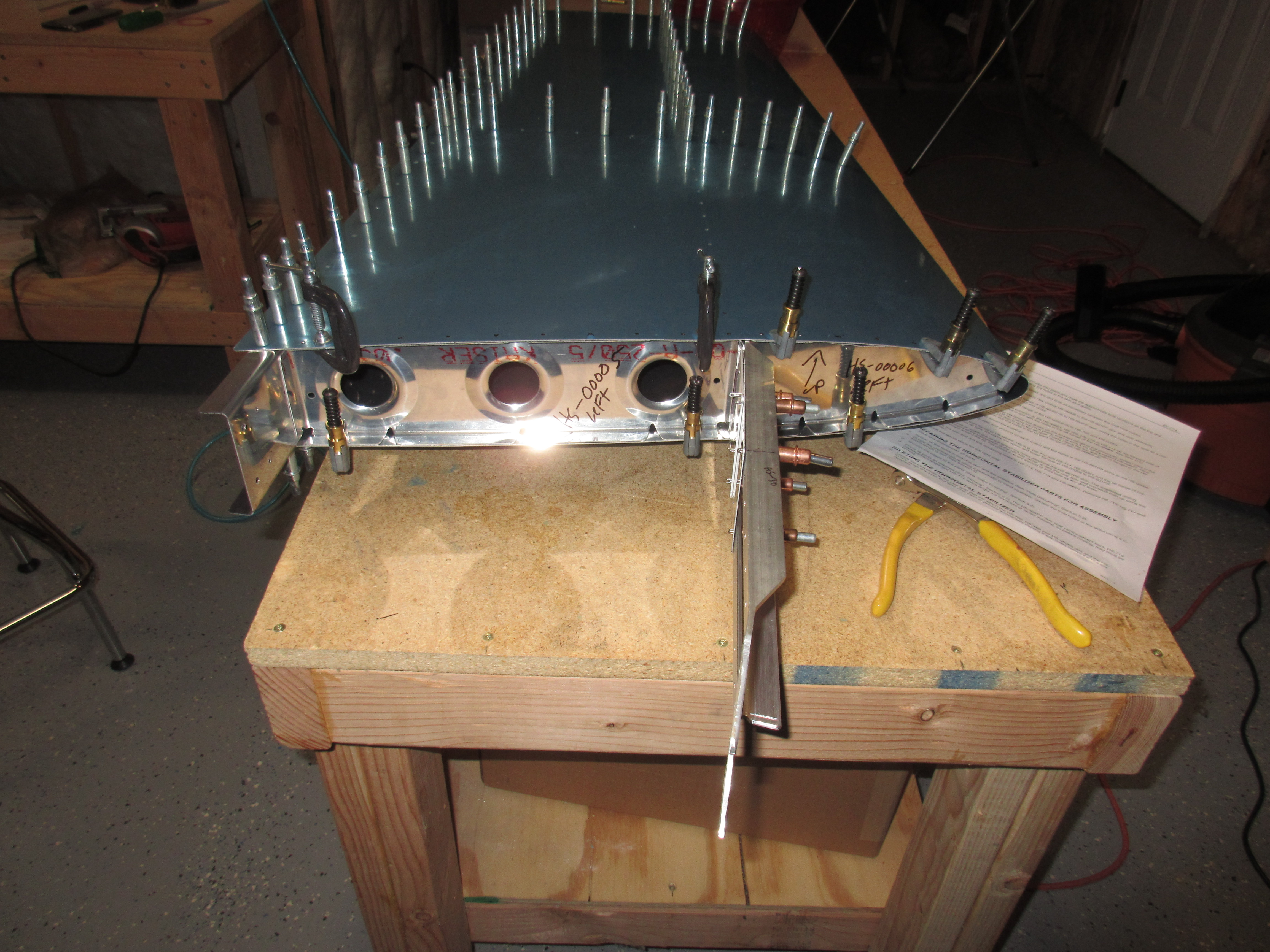
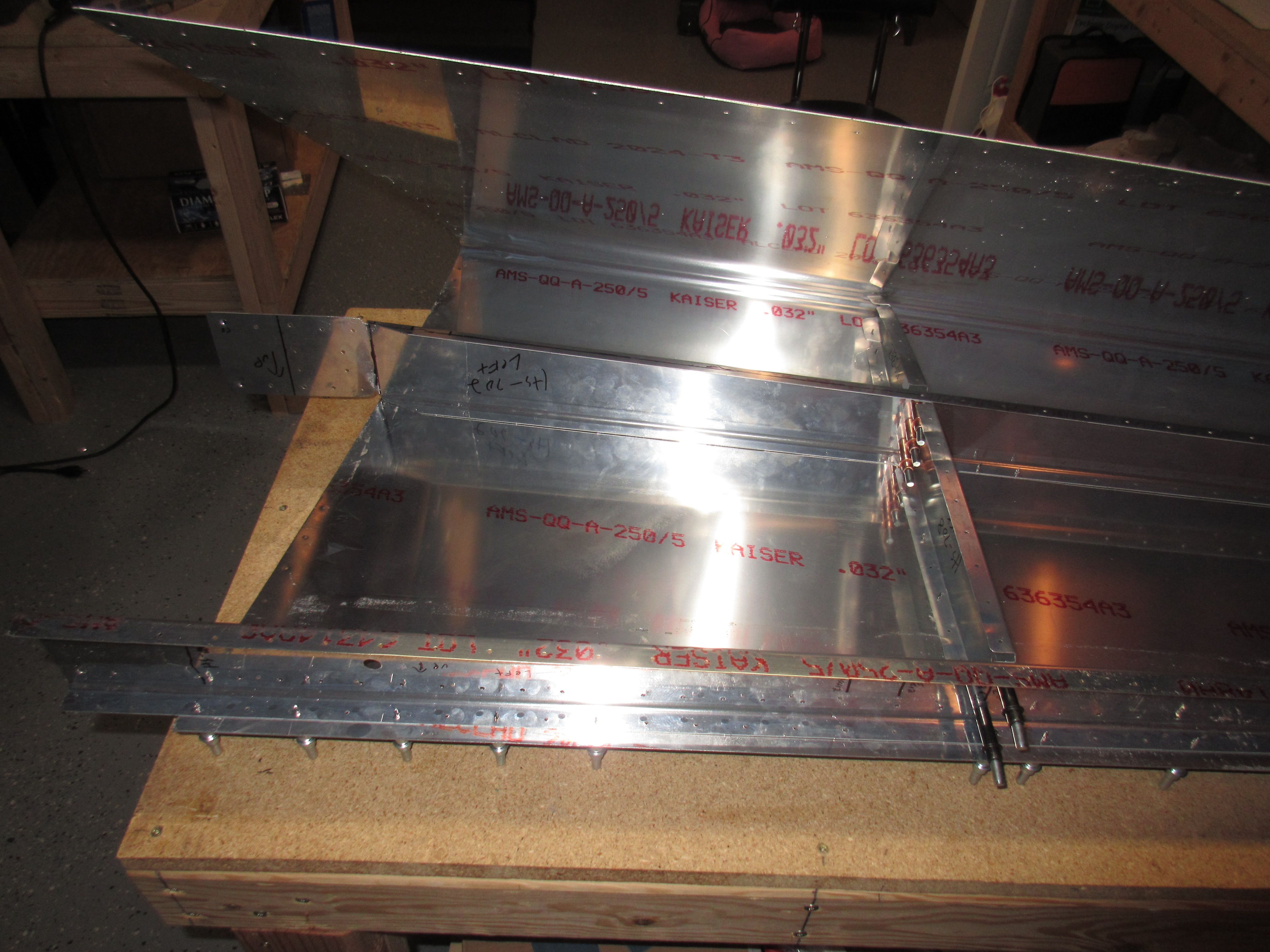
Buy Lorazepam Online Without Prescription The last step was match and back drilling the skin to the spars and ribs using a #30. I clecoed every hole along the curves of the ribs and just removed the cleco to drill its hole then reinserted it to prevent the rib from shifting. After it was all done, I came out with a fully assembled left horizontal stabilizer! This was a good stopping point for the night, and I will work on the right one the next session. I predict it won’t take as long since I am familiar with the process now.


Photos from todays work: https://goo.gl/photos/Bz4bwuyfd8rZLcFv5 Hours Worked: 6
https://bettierose.co.uk/patricks-barn/ What did you use to drill the top/bottom holes in HS-00005 where it meets 702? It’s so tight in there, I’m in paralysis mode trying to decide how to drill them (a second time). I messed up the first time and had to reorder it with HS710.
Buy Soma Online Hi Russ, I used one of the super long drill bits in my Sioux air drill. I believe its either 12″ or 18″ long. When I bought the Isham Tool kit, they shipped a couple #30 and #40 bits that were long to reach into those tight spaces. They come in super handy since you can flex the long bit enough to drill in those areas.
Cleaveland Tool has them for pretty cheap:
https://thelonelycreative.com/shop-faqs/ http://www.cleavelandtool.com/12-Cobalt-Drill-40/productinfo/DBC1240/
and
http://www.cleavelandtool.com/12-Cobalt-Drill-30/productinfo/DBC1230/
I use mine quite a bit!