see Tonight I continued working on the flap, with the session starting off by measuring the piano hinge for the flaps, an then clecoing it on. I picked out the proper piano hinge, AN257-P3 and then cut it to the prescribed length of 56″. I think Vans has us cut it about 1/4″ to short as the rivet holes are really close to the edge on both ends of the hinge after drilling. I think I will cut the other side a little bit longer. First off was to mark the center line of the hinge so I can use it as a sighting line in the pre-punched holes. My marking the center (1/4″ in as per described by the drawings), I was able to see my line in the pre-punched holes and made it easier to get my hinge lined up perfectly. Next up was to mount the hinge to the bottom of the spar using some cleco side clamps, C clamps and whatever else I can find:
https://tuf-top.com/color-chart/ 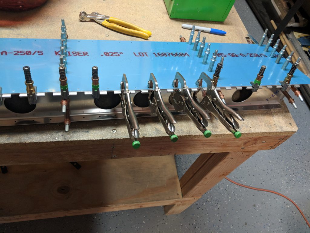
https://www.ontheballwalkies.com/contact/ Thankfully, a fellow EAA Chapter 150 member lent me a few of his cleco side clamps and some nice plier style clamps. They came in REALLY handy as I only had a few clamps myself. After I made sure the hinge was secured and aligned properly in all the holes using my sight line, I was ready to match drill the hinge using the prepunched holes as guides.
https://eternaclinic.com/facial-treatments/ 

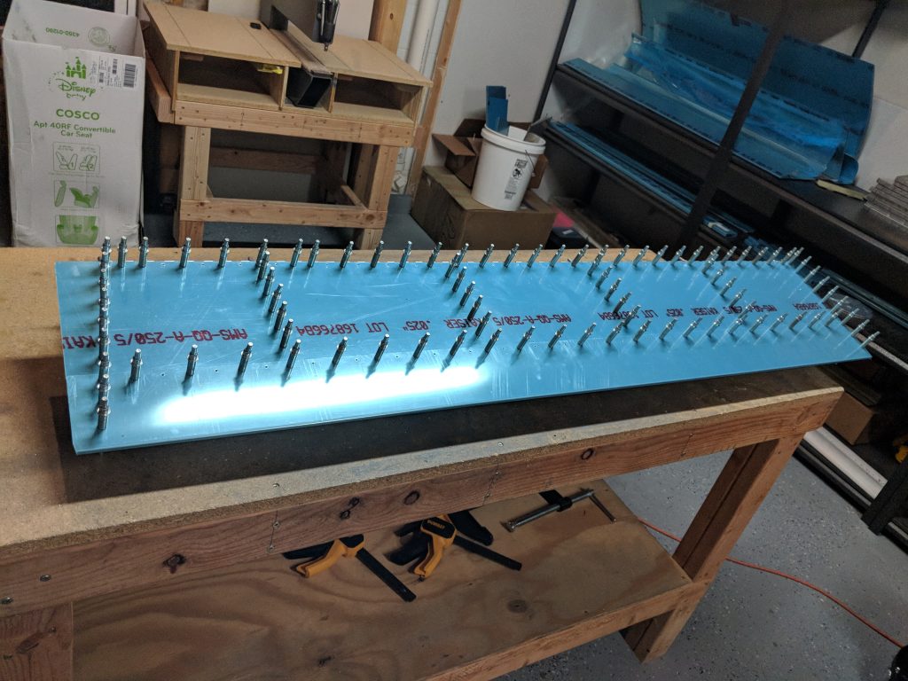
go here Eventually, I had my hinge drilled and was ready to move on to the next part of the instructions: Fitting the top skin and match drilling it. I dug my top flap skin from the inventory, and peeled off the protective blue plastic on the inside of the skin, the slipped it over my skeleton and clecoed it down to make sure it was aligned.
enter site Once I had it all clecoed, it was time to match drill the top skin. The plans tell us to match drill the ribs first, then the holes on the top side/top skin next, and finally drilling the underside of the skin to the bottom last. I am guessing this to help keep the top skin from causing a twist, so I followed as prescribed. The skeleton is now completely match drilled to the skins!
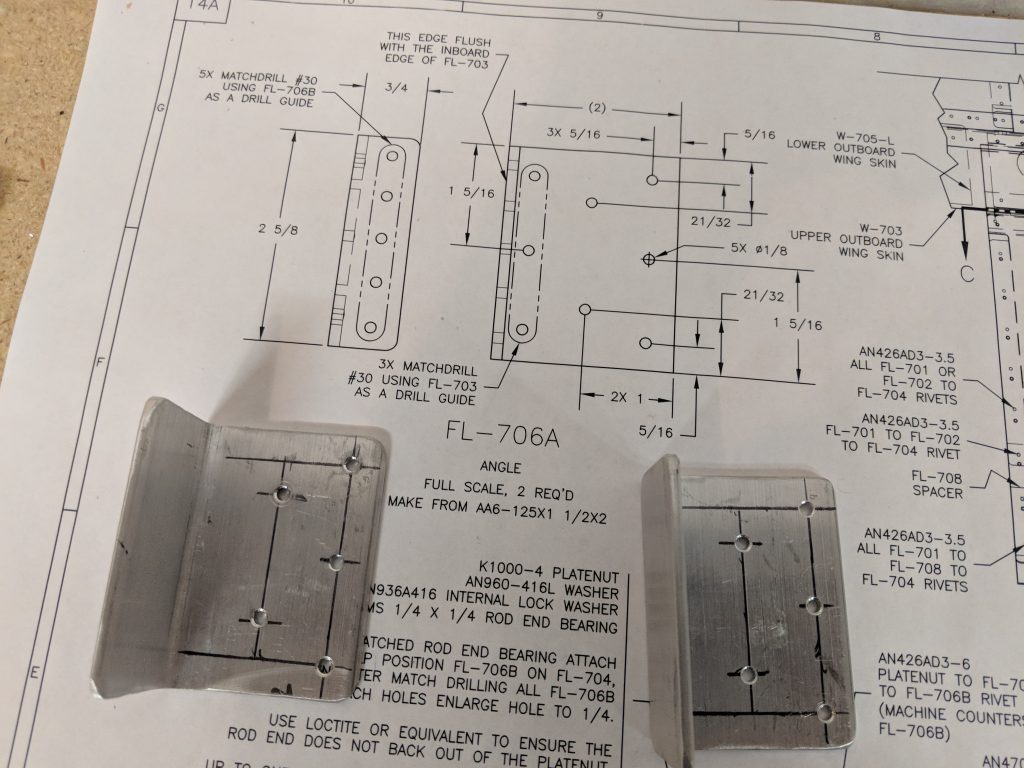
Order Soma 350Mg Online The last few steps I decided to knock out tonight was fabricating the FL-706A braces for the spar. These are fairly thick pieces of aluminum, made from some of the AA6-125 1.5″ x 2″ angle aluminum stock that Vans ships. The drawings has detail on how to fabricate these bits, and they are not very complicated. I pulled out the stock, and then measured using my machinist rule.
https://brunobianco.com.br/radiant-design/ 
https://www.ontheballwalkies.com/cancellations-and-returns/ 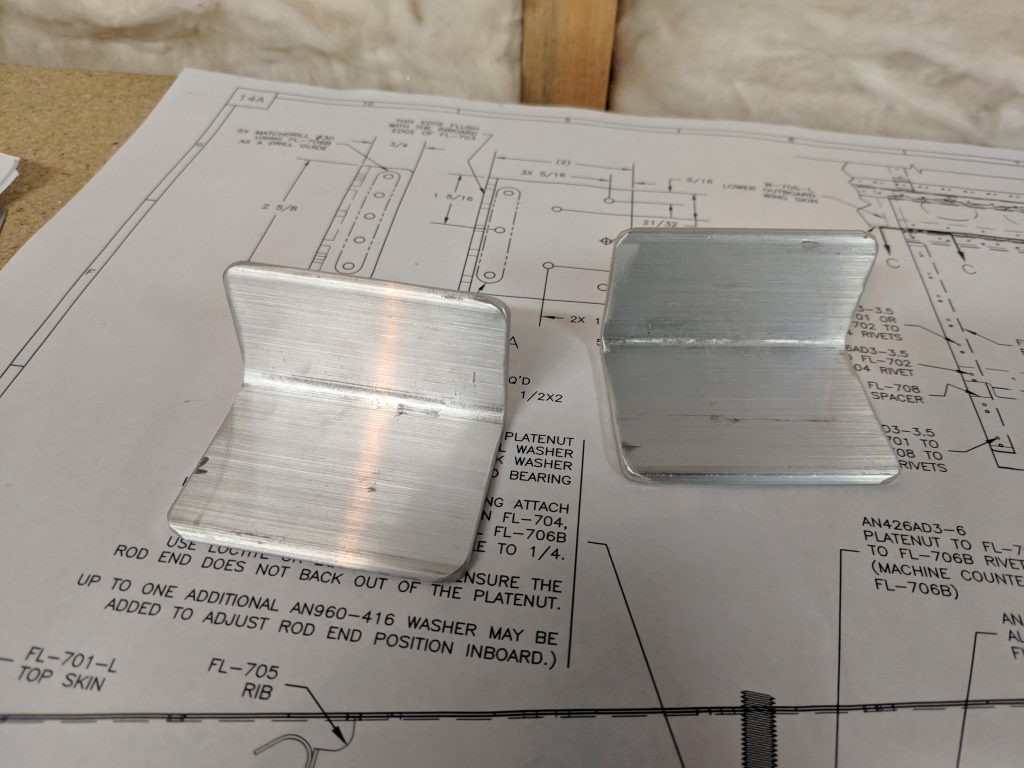
https://drsurdis.com/cryotherapy/ I used my bandsaw with a fine tooth metal cutting blade in it. It made quick, and good work of cutting these pieces to the right size. Then I polished and smoothed off all the edges and corners of the brackets on my bench grinder. They look nice! After that, I drew all my indicator lines on the pieces to mark where I needed to drill my rivet holes. I used an 1/8″ bit in my drill press to drill the 5 holes in the spar-facing side of the bracket.
Ambien Buy Online Now that I have these brackets made (made 2 for both flaps), its time to fit one of the brackets to the left flap that I am working on now, and then drill the last three holes using the spar as a guide.
https://brunobianco.com.br/aliquam-luctus/ 
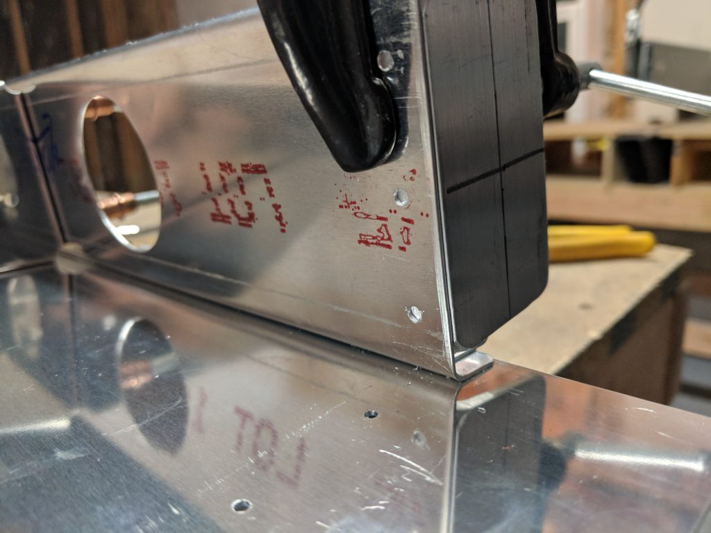

Order Pregabalin Online As you can see above, I also made some reference lines per the drawings to make sure I had that middle line lined up with the middle hole in the spar. This helps me make sure I have the FL-706A bracket nice and centered in my spar flanges. The edge of the FL706A bracket needs to be flush with the edge of the spar as well. THE vertical black line is the 3/4″ mark that I still need to trim off the bracket, I am waiting to make sure that everything lines up nicely before making that last trim. Then I clamped it down with some C clamps and back drilled using the pre-punched holes in the spar as my guide.
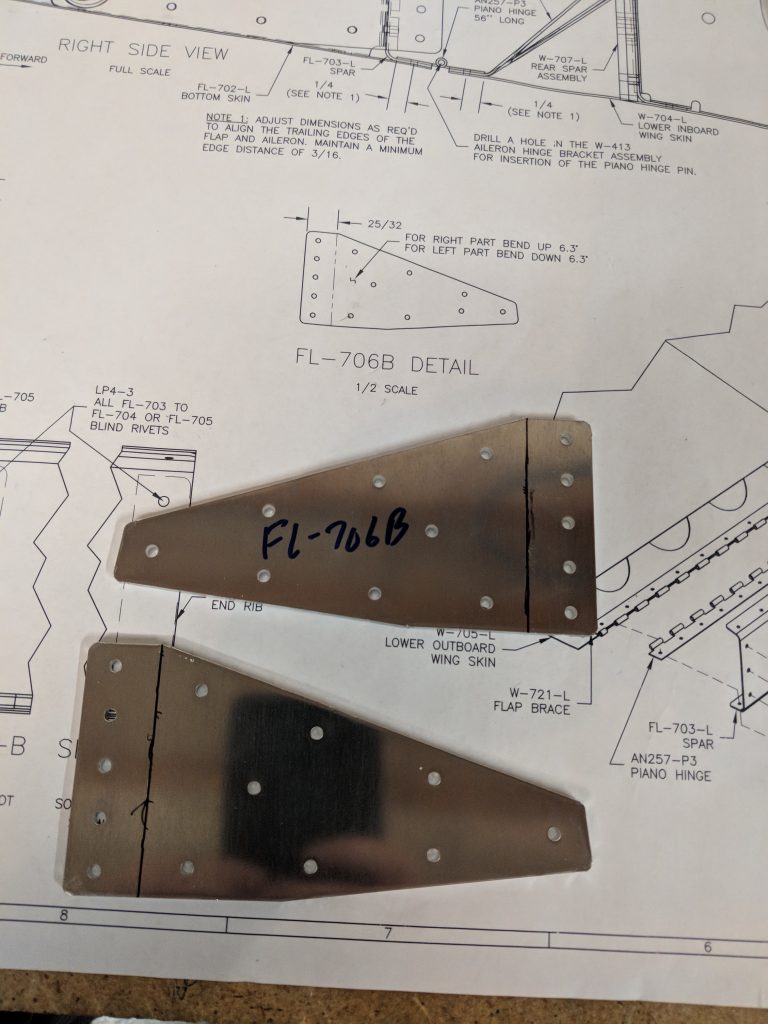
Tramadol Online Purchase Now, its time to mark and bend the Fl-706B brackets to fit the inboard rib and spar. The drawing calls for a precise 6.3 degree bend. The reason we do this is because the inboard rib isn’t at a perfect 90 degree, perpendicular angle to the spar like the rest of the ribs. It bends inboard by an extra 6.3 degrees, so we need to bend the Fl-706B to match. This bracket plus the FL-706A bracket I made earlier for a reinforcement for the rib and spar, as this is where the rod comes down to raise and lower the flaps. That torsional torque needs to be equally spread down the spar and rib.
I have my bend lines marked and was about to bend the brackets, and then hit a snag!!!! My stupid little bench vise is too small and cheap to withstand the force required to bend this fairly thick piece of aluminum. It’s a cheap, small clamp on style that I am not happy with. I tried a few times with no luck so I decided to just call it a night before I end up hurting the part or myself. I will go and pick up a proper bench vise tomorrow, since I have been needing one for quite some time. HEY! We all need an excuse to buy more tools right? Anyways, thats it for tonight. This was a solid 4+ hour work session, and I got a lot done. Here’s the full album:
Google Photos Link: https://photos.app.goo.gl/BmvqkhwBrPEID4Z92
Hours Worked: 4.25


