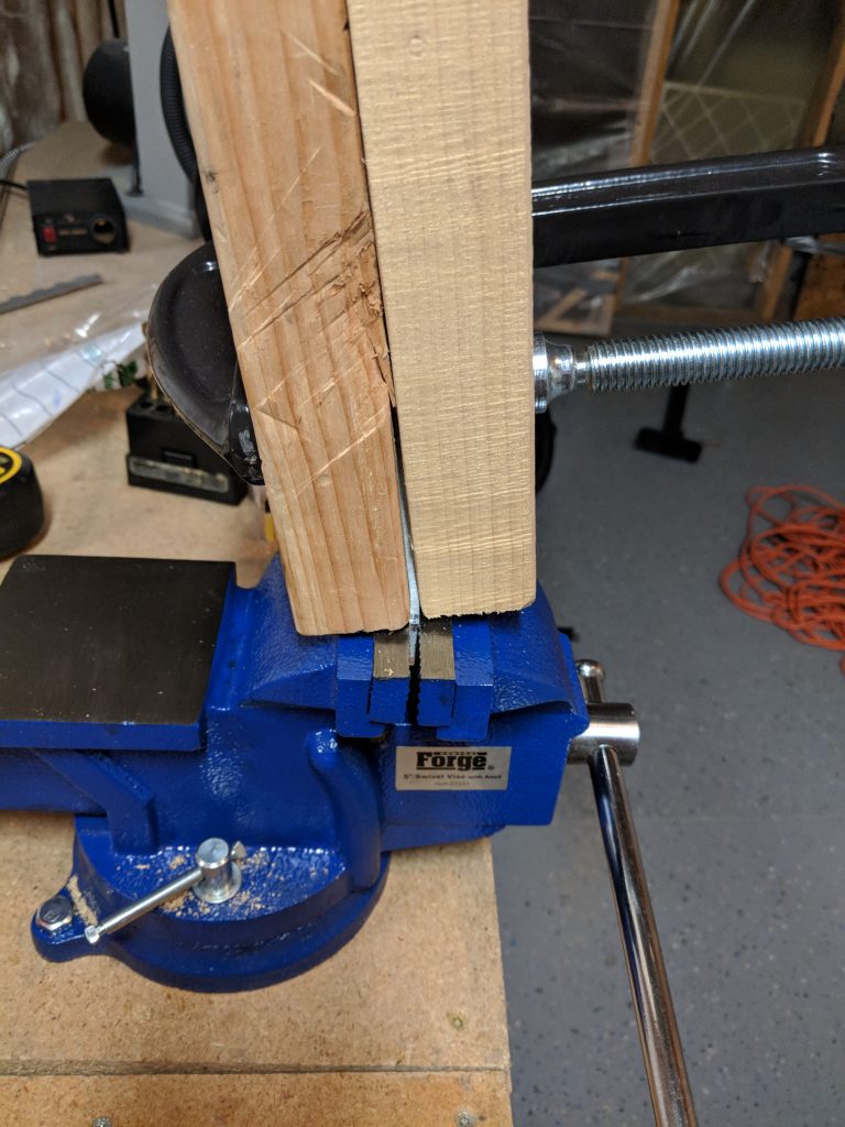
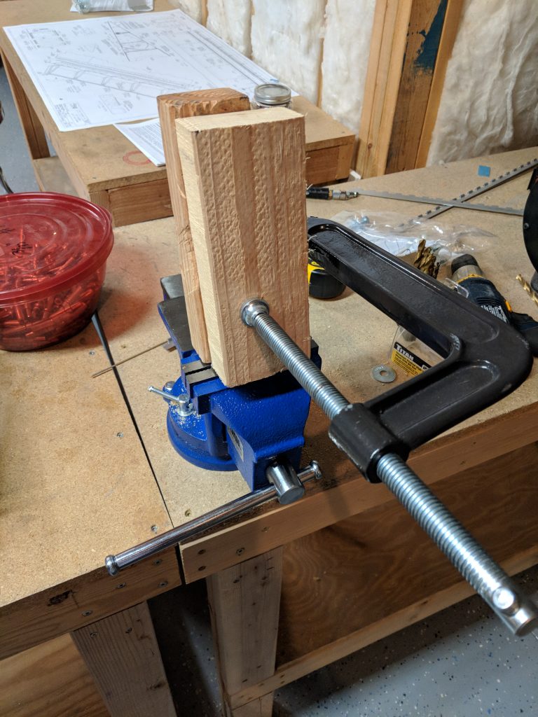
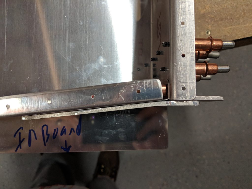
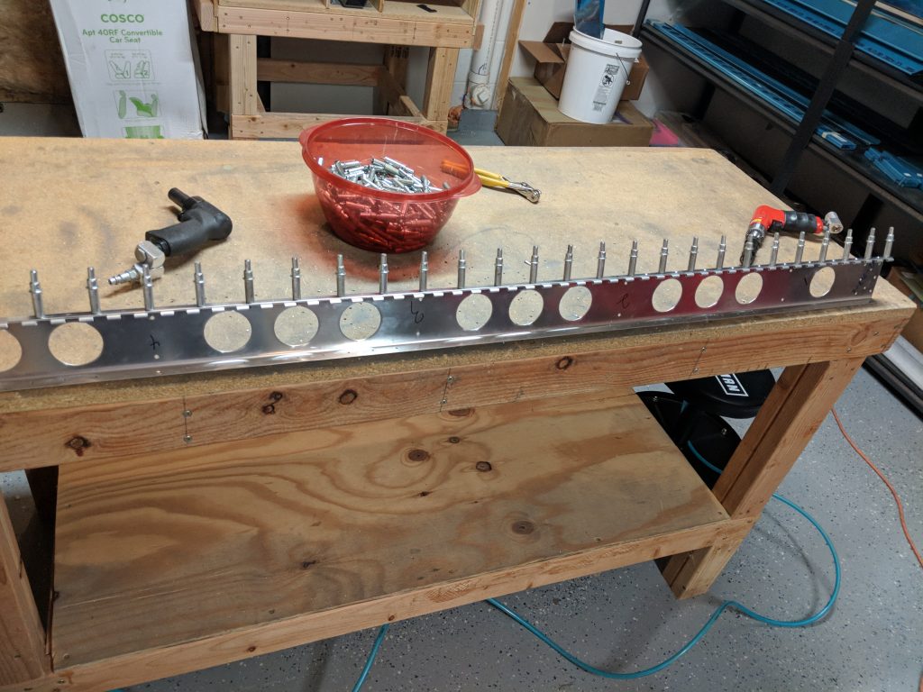
Buy Tramadol Without Prescription I found a Harbor Freight 25% off coupon, so what better time to buy a bench vise 🙂 I wound up with a semi-cheap 5″ vise that should do all I need it to. I drilled some mounting holes in my work bench and bolted it down and got right to work on bending the FL-706 doubler bracket. I chucked it up in the vise, and then clamped some scrap 2×4 boards around the piece to make sure I got the bend to occur where I wanted it. It worked out pretty good, I had to make a few trips back and forth to the flap rib to test fit, and bend a little more to get it perfect.
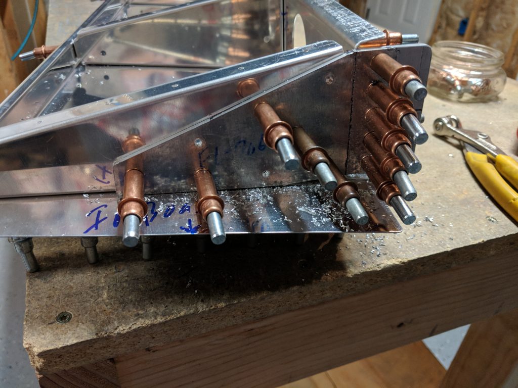
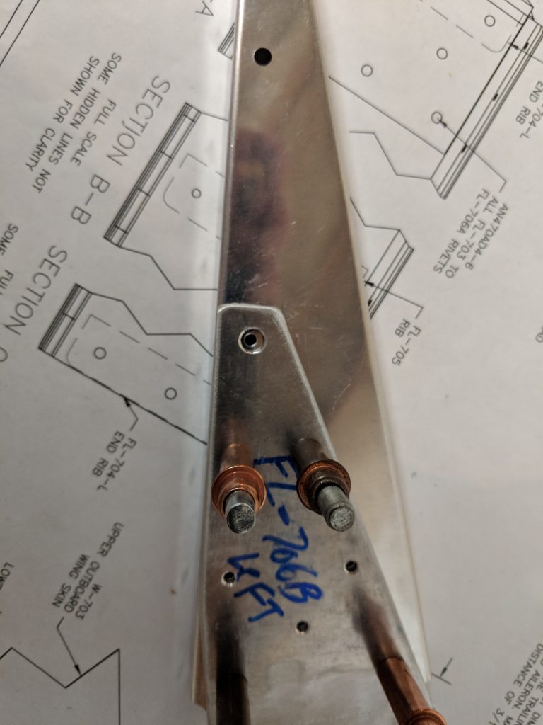
Buy Ultram Online Once I had that 6.3 degree bend made, and had it lining up nice and flush against all the end rib, spar and spar doubler, I match drilled the doubler. This was a bit tricky, as there is only one hole that is pre-punched in the rib and FL-706A doubler. I used it for initial alignment, and then squared it up with the FL706-B doubler and then used some C-clamps to hold everything tight while I back drilled.
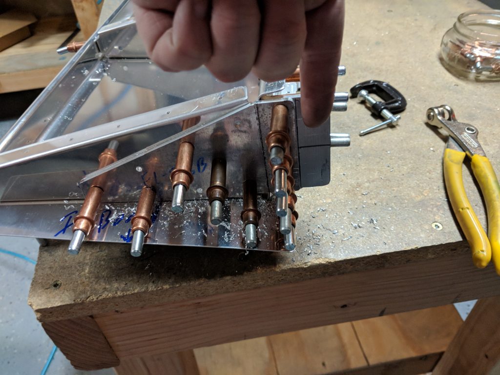
Buy Ambien Online Overnight I didn’t get any photos of my C-clamps, but they were just clamped onto the forward end of the FL-706A doubler and the FL-706B doubler. Then I drilled the holes into FL-706B using the holes in FL-706A as my guides, clecloing them as I went. Once that was done, I back drilled the holes in the FL-704 end rib using FL-706A as a guide, again clecoing as I went to hold things still. One that was done, I decided it was tie to cut off the excess material from FL-706B spar doubler, as I had left it on purpose to help with clamping and aligning. I am glad I did that, since it worked out pretty nicely. My finger below is pointing to this excess that needs trimmed.
Get Online Xanax Prescription I trimmed it using my bandsaw and then removed both doublers as well as the FL-704 end rib to finish up the last little bits of work on them. I need to open up the very end hole on FL-706A (in the trailing edge most end) to make room for the 1/4 bolt that connects the flap to the flap motor/pushrod. It’s attached using a K1000-4 nutplate that goes on the inside of the flap. The first step was to enlarge the #30 hole into a 1/4″ hole in both the FL-706A doubler and the FL-704 end rib. I wanted to make sure this hole was drilled true so I chucked up my 1/4″ bit in the drill press and used it to enlarge the hole on the thick doubler. Then, I clecoed the doubler back onto the end rib and used that new larger hole to match drill the end rib hole.
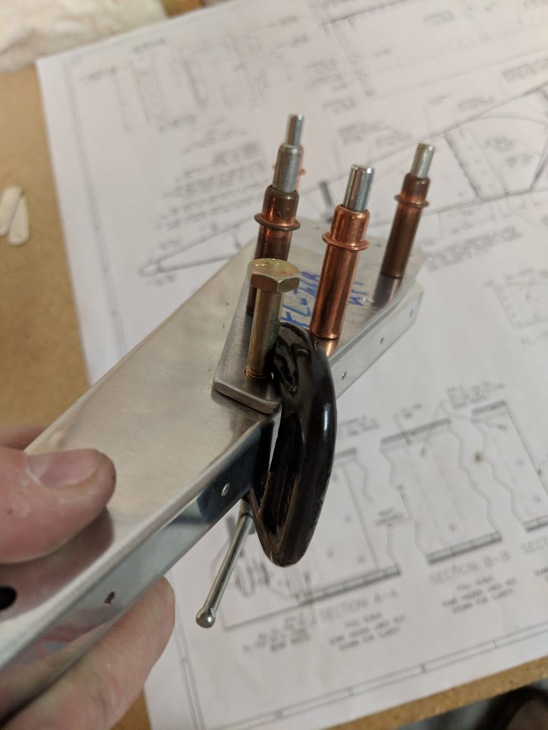
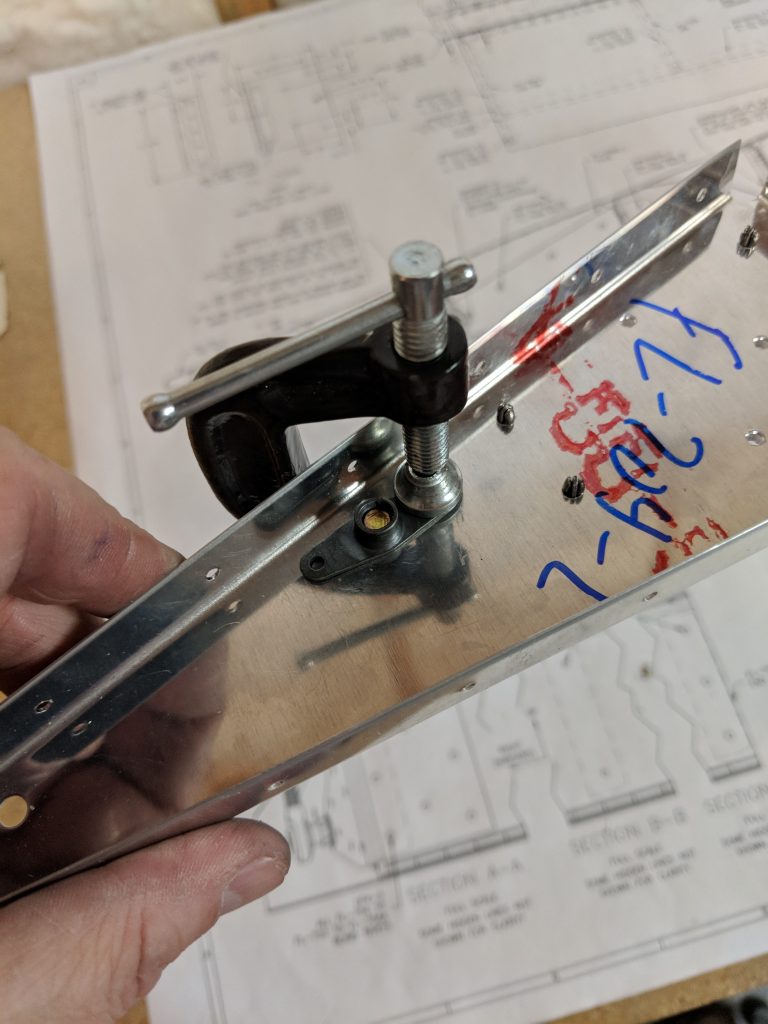
Buy Tramadol 100 Mg Online To make sure I got this lined up correctly, I picked out an AN4 bolt from the supplies and a K1000-4 nutplate. I threaded the bolt through the doublers/rib and put the nutplate on the back. Then I use a C-clamp to hold one leg of the nutplate so I could drill the other leg.
source link Then I back drilled the rib and doubler using the nutplate as the guide. Once I had one hole drilled, I stuck a cleco in the new hole and removed the C-clamp an drilled the other hole in the nutplate. Now that the holes for the nutplate were drilled, I had to countersink them. We countersink one hold on the FL-704 end rib and then the other hole is actually in the Fl-706A doubler. I used my countersink bit screwed into my deburring handle so I could gingerly countersink the thin metal on the rib. I used a spar AN426AD3-7 rivet to check my depth, and then did the same on the doubler.
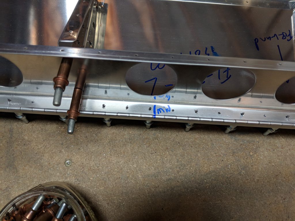
Order Diazepam Online The last step for tonight was to countersink the bottom of the spar. We are going to dimple the skin, so we need to countersink the spar to accept the skin dimple. The reason we are not dimpling the bottom of the spar, is because we also have the hinge that gets attached to the other side of the spar flange. Countersinking only the spar to accept the skin dimple is a much easier process than dimpling the spar and THEN countersinking the hinge to accept the spars dimple. I clamped the spar down to my work bench to make it easier and then clecoed on the hinge. Van’s tells us to cleco the hinge so that the hinge can act as a guide for the countersink bit’s pilot. It actually worked out really well.
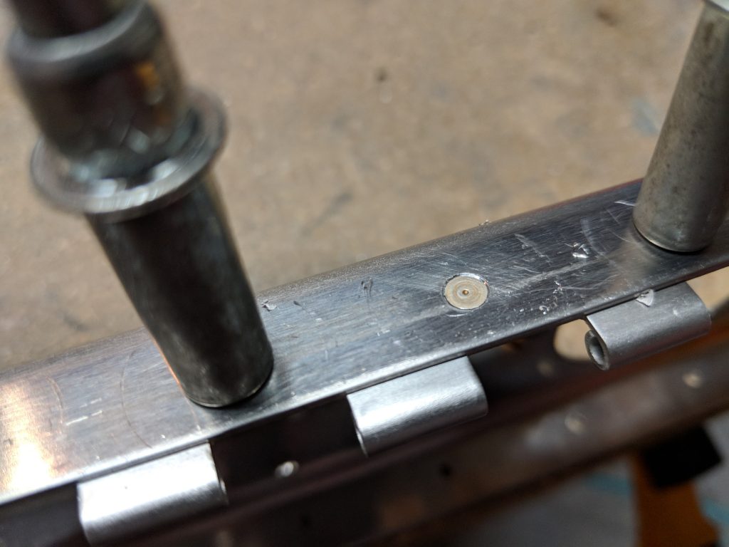
https://eternaclinic.com/contact/ I clecoed the hinge using every other hole and then countersunk the empty ones using the microstop countersink. I used a spar AN426AD3-7 rivet to help me gauge the correct setting for the microstop, and then used it about every fourth hole to make sure the depth is still correct. Once I had the holes done, I moved the clecos and countersunk the remaining ones.
https://www.turtleopticians.com/contact-us/ One last little step before I take the hinge off. Vans gives us two options for the hinge pin installation. #1: you can drill a hole in the aileron mount to insert the hinge pin through and then into the flap hinge or #2: you can remove a few eyelets in the middle of the flap hinge and cut the hinge pin in two pieces to allow room to insert the hinge pins into the flaps from the bottom of the flap. What we are essentially doing is making a left and right hinge on the flap, and making room in the middle to insert the left and right hinge pins. This is the method I think I will go with, so I went ahead and marked my hinges where the middle is. I will cut the eyelets when I do the initial mounting on the wing. This way I can make sure I cut them where I have room to safety wire them down somewhere.
And thats all I accomplished tonight. The left flap is ready for hole deburring, and then dimpling. I am thinking I will wait until I get the right flap to this same stage, and then just debur and dimple all the pieces to both flaps at the same time. From there, it will be time to prep for priming, and prime, followed by final riveting. I am still deciding if I want to continue spraying AKZO for the wing components, or switching to just alodining them. I’ll give it some though between now and then. Here’s all the photos from tonights work:
Google Photos Link: https://photos.app.goo.gl/OtSXkExzF3nicROc2
Hours Worked: 3.0


