


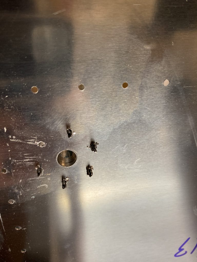
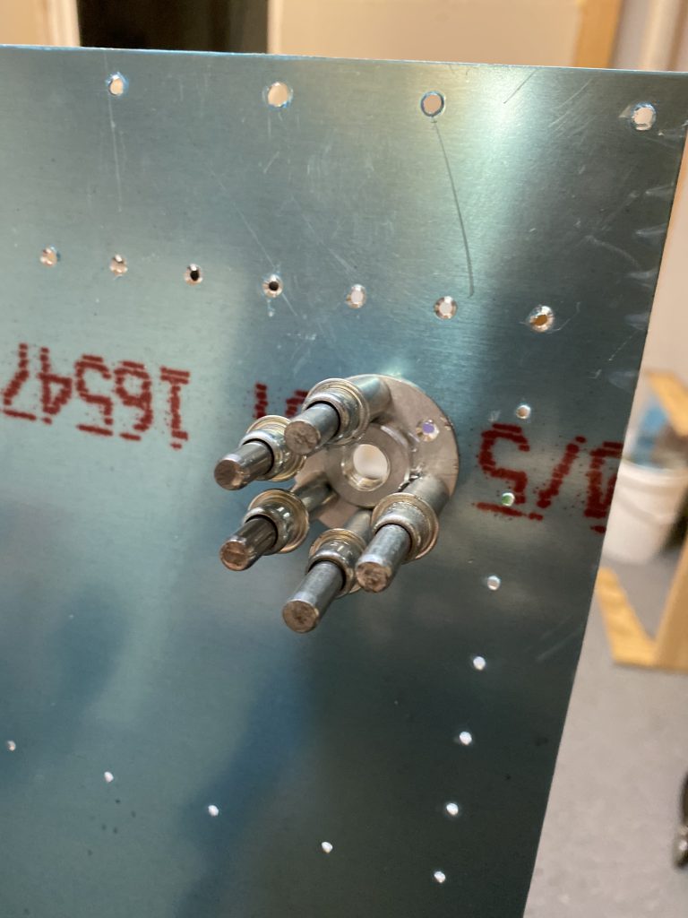
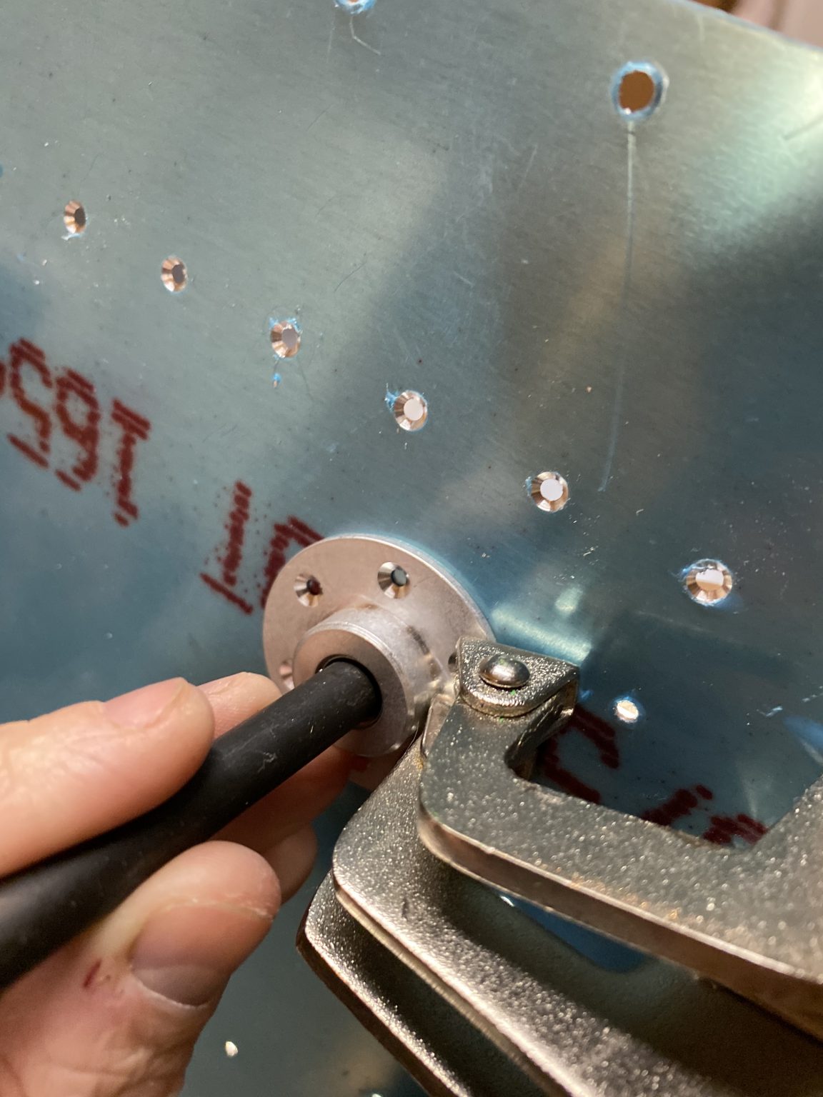
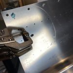
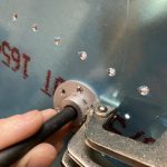
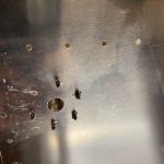
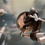
Tonight was a fun build session! Since all the tank structure is pretty much fitted and done, I needed to knock out the last few little bits of tank parts: The tank drains (sumps) and the fuel caps. I’ve been sort of looking forward to doing this work to be honest. I decided to start out with the easy stuff first and then work till I was tired. That meant fitting the tank drains (aka “sumps”). We need to center the VA-112 drain flange over the pre-punched drain hole in the tank skin and use the flange as a guide for back drilling the tank skin. I didn’t want to eyeball this, so I pulled out my assortment of center punches and found one that was almost the same size as the hole in the drain flange and used it as a guide to center the flange on the skins hole.

Once I had it centered up, I used some vise grip clamps to hold it in place so I could back drill the skins rivet holes using the flange as a guide. I’d drill a hole, and then insert a cleco immediately in the hole and then move across and drill another hole and repeat the process. This assured I’d have the flange nice and flush on the tank skin and everything lined up.
 .
. 
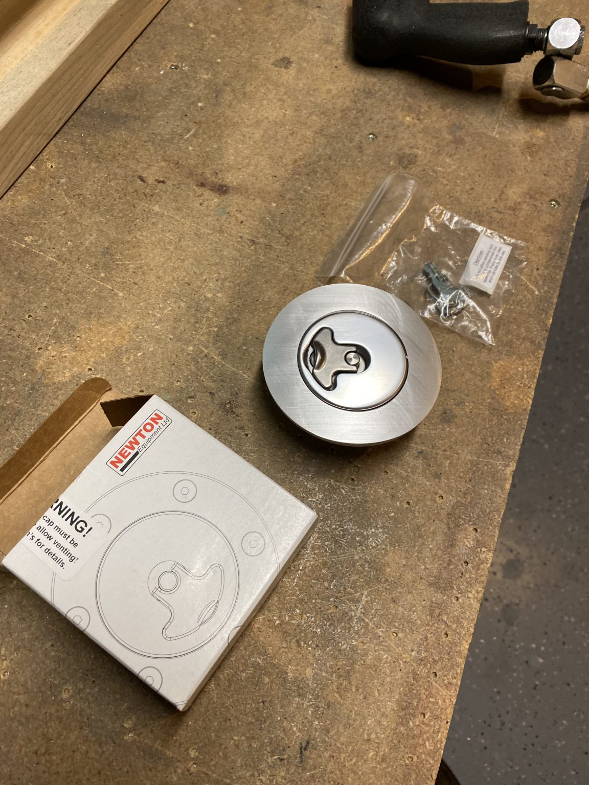
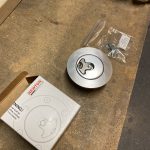
After I had the flange drilled, I removed it, and then deburred the rivet holes with a deburring tool, and done the exact same process to the other tanks flange. The flanges shipped machine countersunk, so I didn’t have to do any countersinking on them, but I did check their depth by inserting a rivet and making sure the head would be nice and flush. I decided to start working on the next cool part: The fuel caps. I had ordered the upgrade Newton style “Deluxe” fuel caps when I ordered my wing kit, from the suggestions of many other builders, and these things are AWESOME!

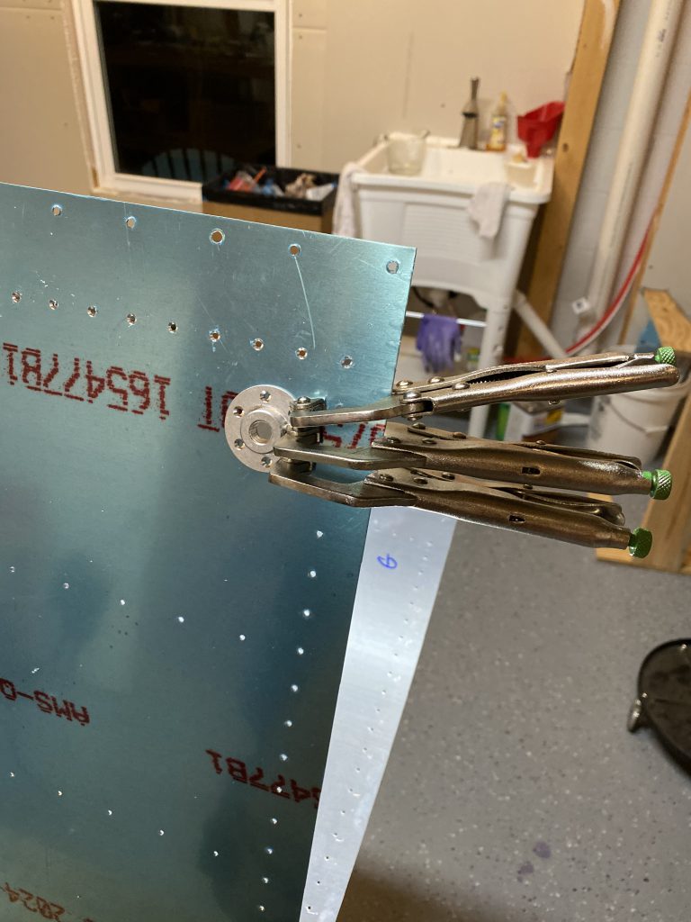
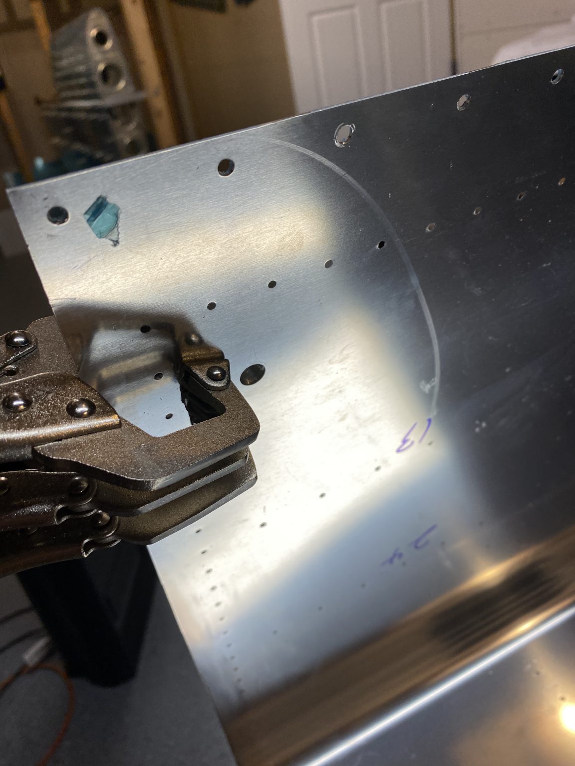
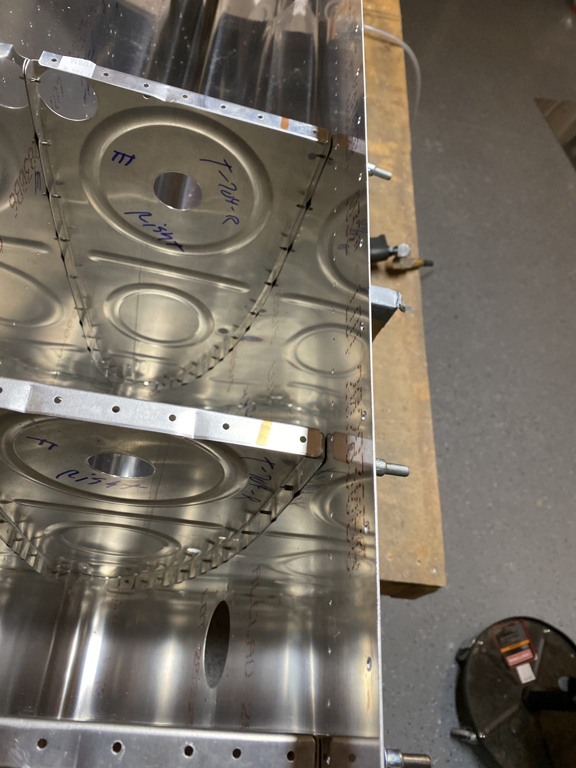
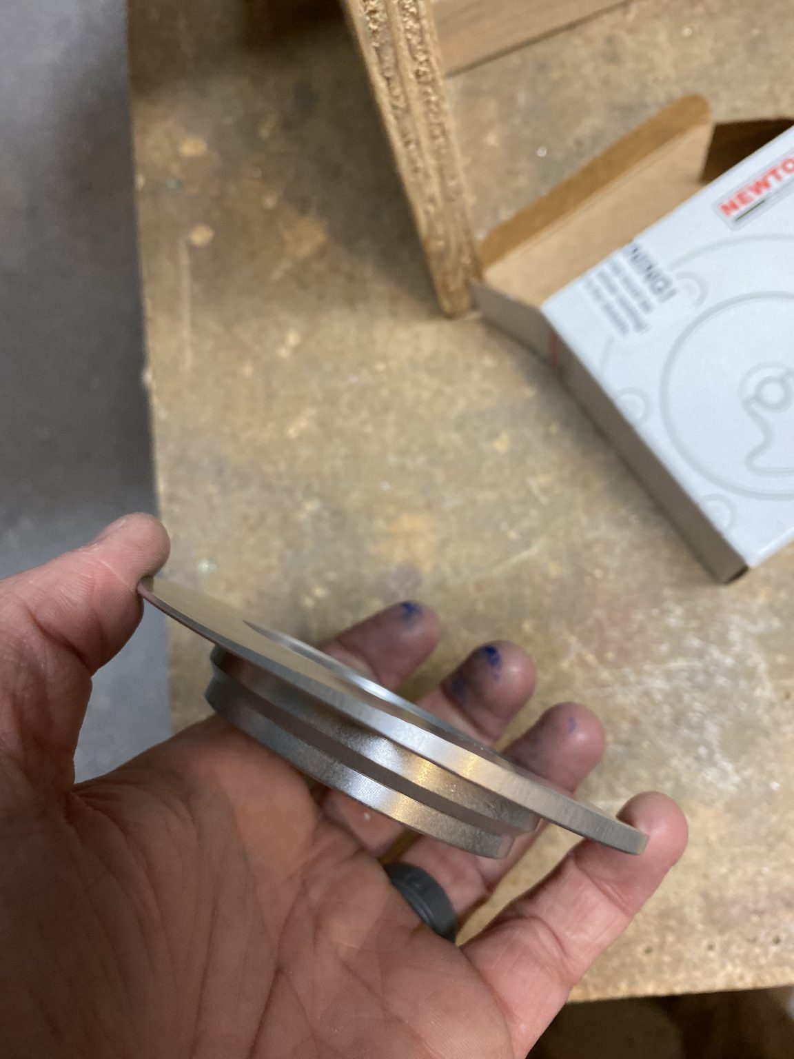
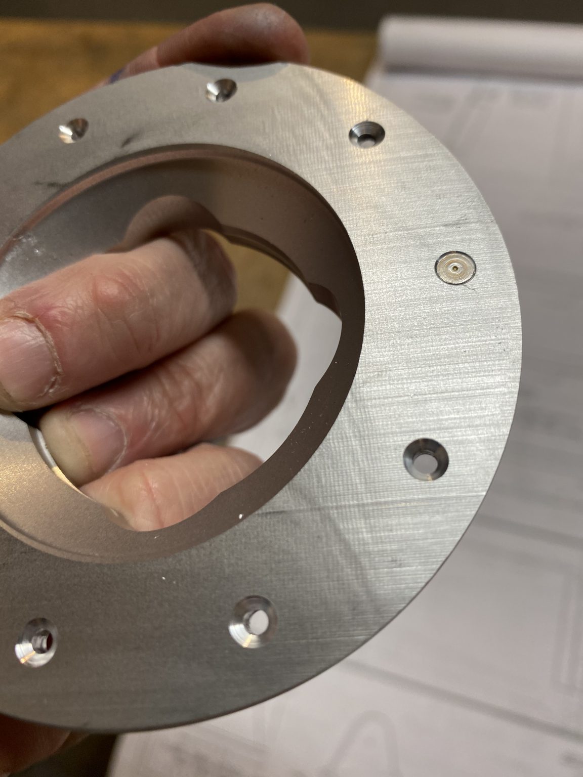
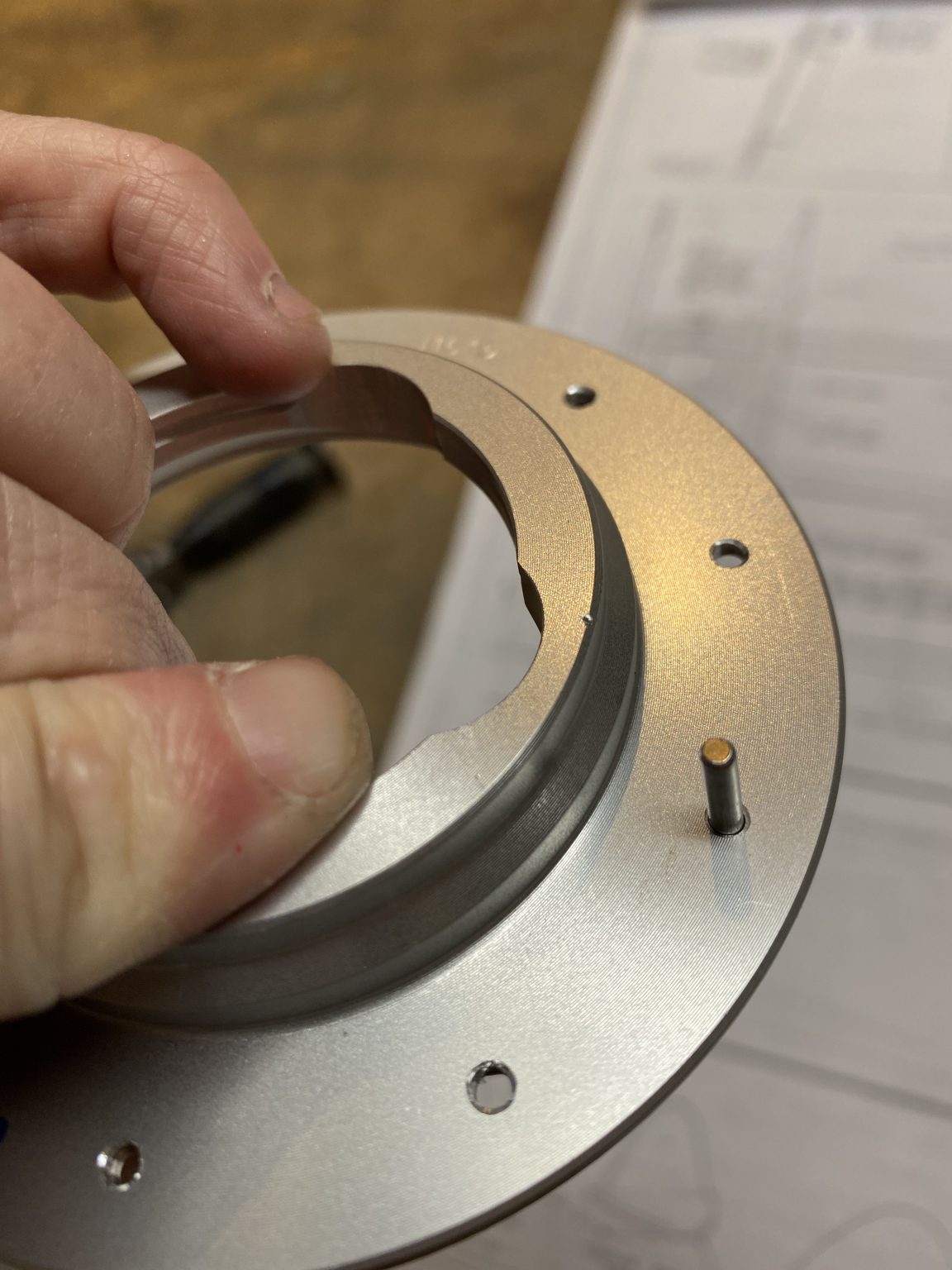
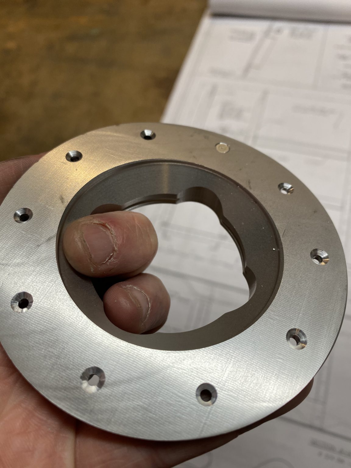
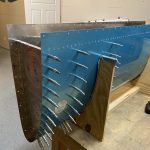
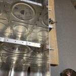
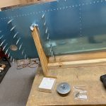
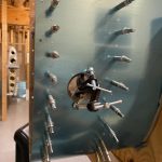
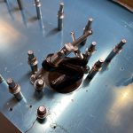
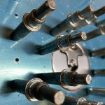
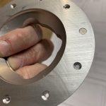
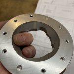
They ship with a nicely machined flange that is shaped to fit the inside curvature of the tank skin, making fitting them pretty easy. On these, the tank skins have pre-punched holes for both the fuel filler hole, as well as the rivet holes that is used to rivet the machined T-406B flange onto. I decided to put my tanks in the stands and cleco in three of the outboard ribs to help the skin hold its correct shape, that way I could get the machined curve in the flange exactly right.
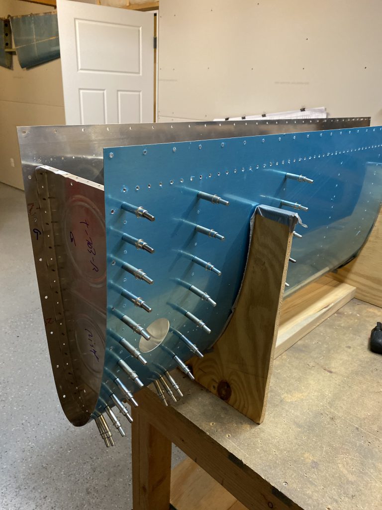
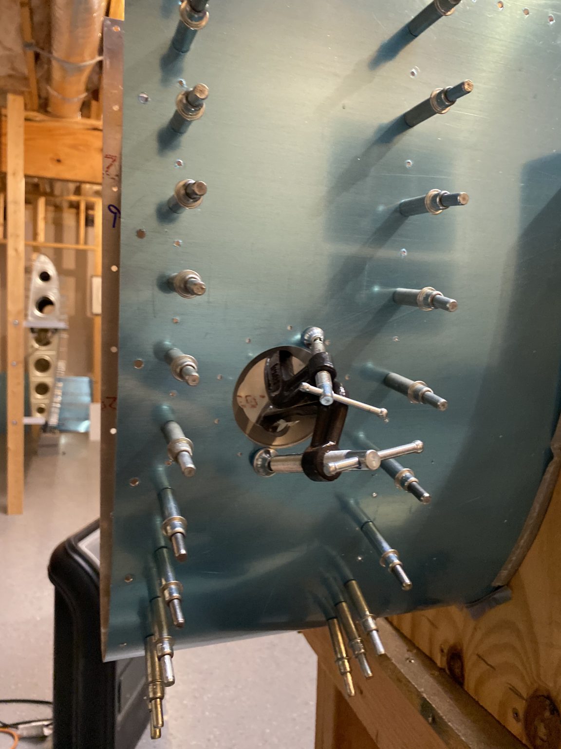
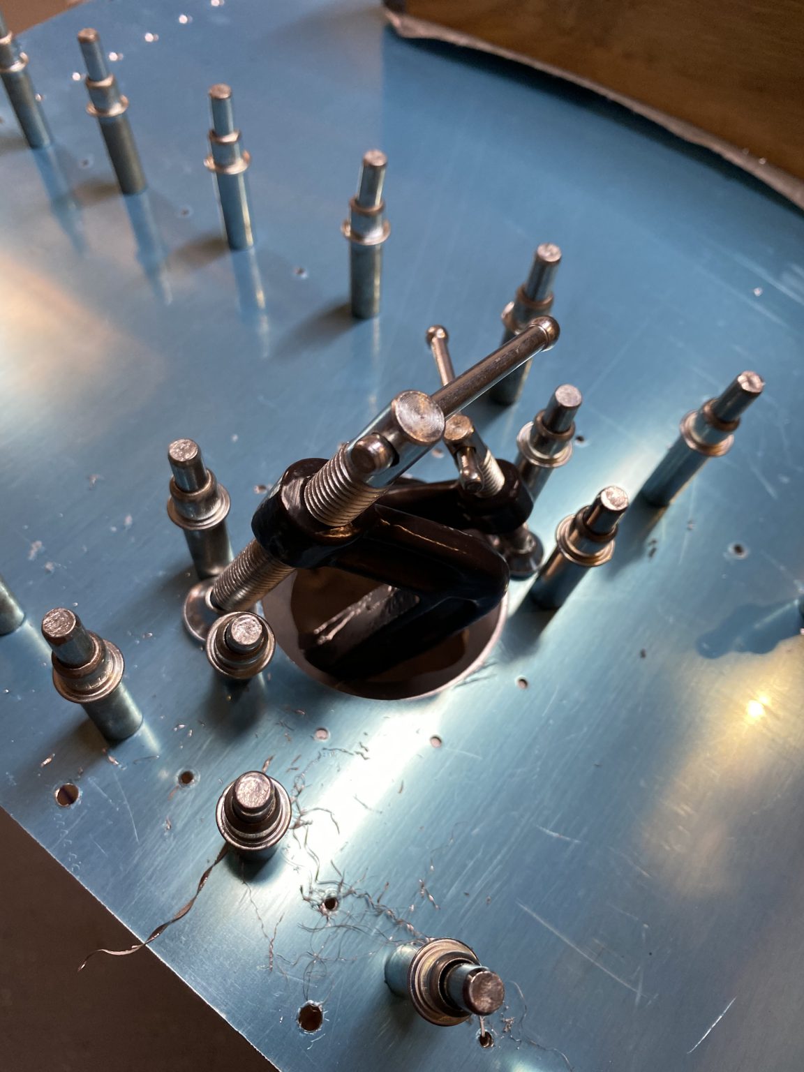
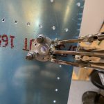
Now it was a matter of lining up the machine parts of the flange with the curve of the tank skin and then using the actual fuel cap as a guide to help center everything up on the pre-punch fuel filler hole in the skin. Once I had everything lined up, I used some C-clamps to help hold the flange in place so I could get the first holes done.
 .
. 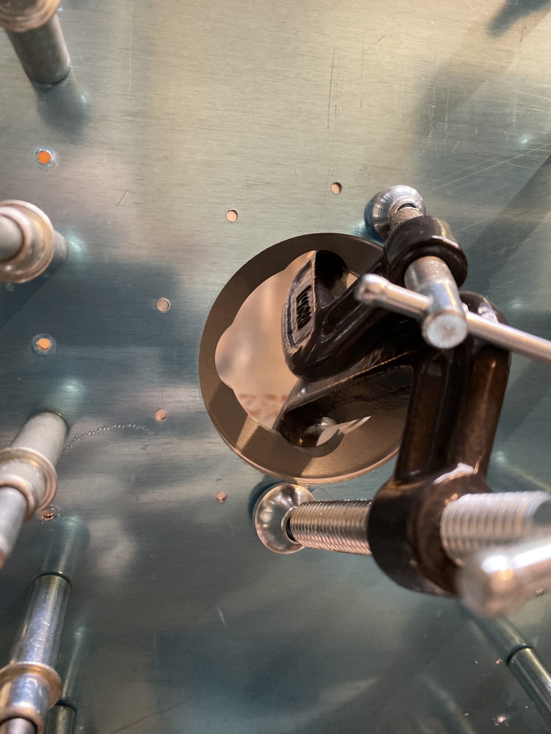
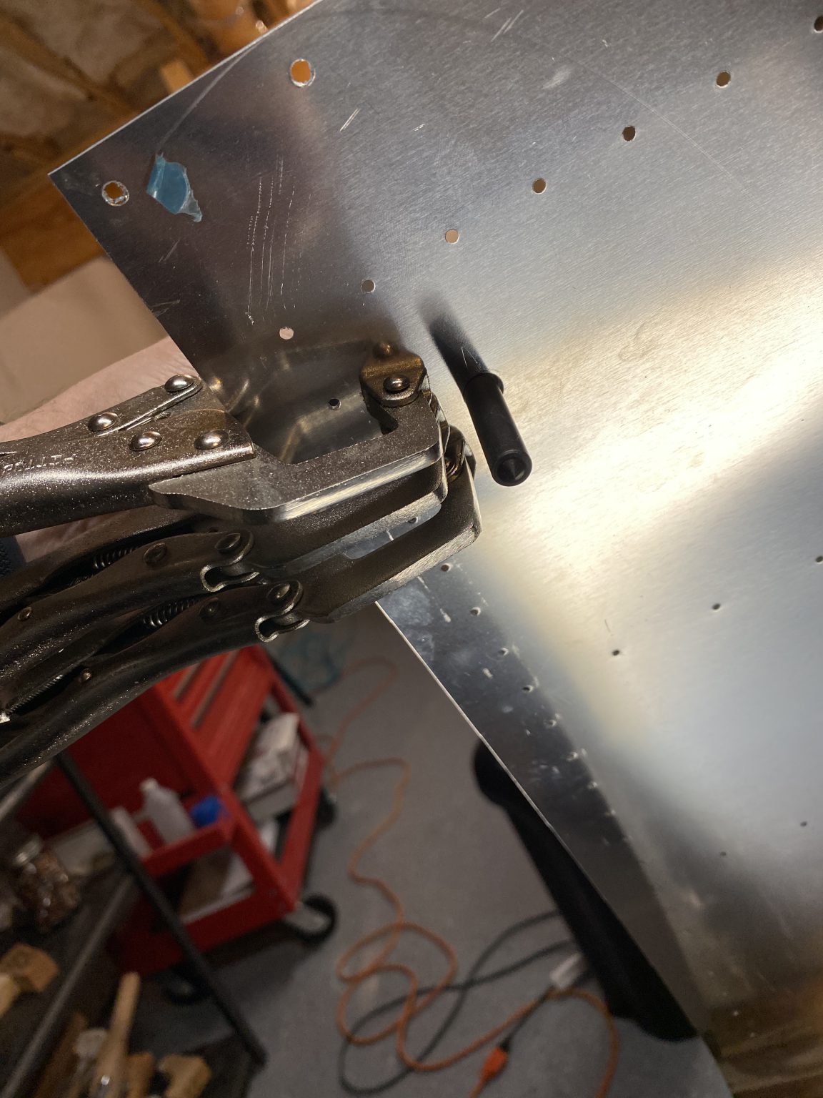
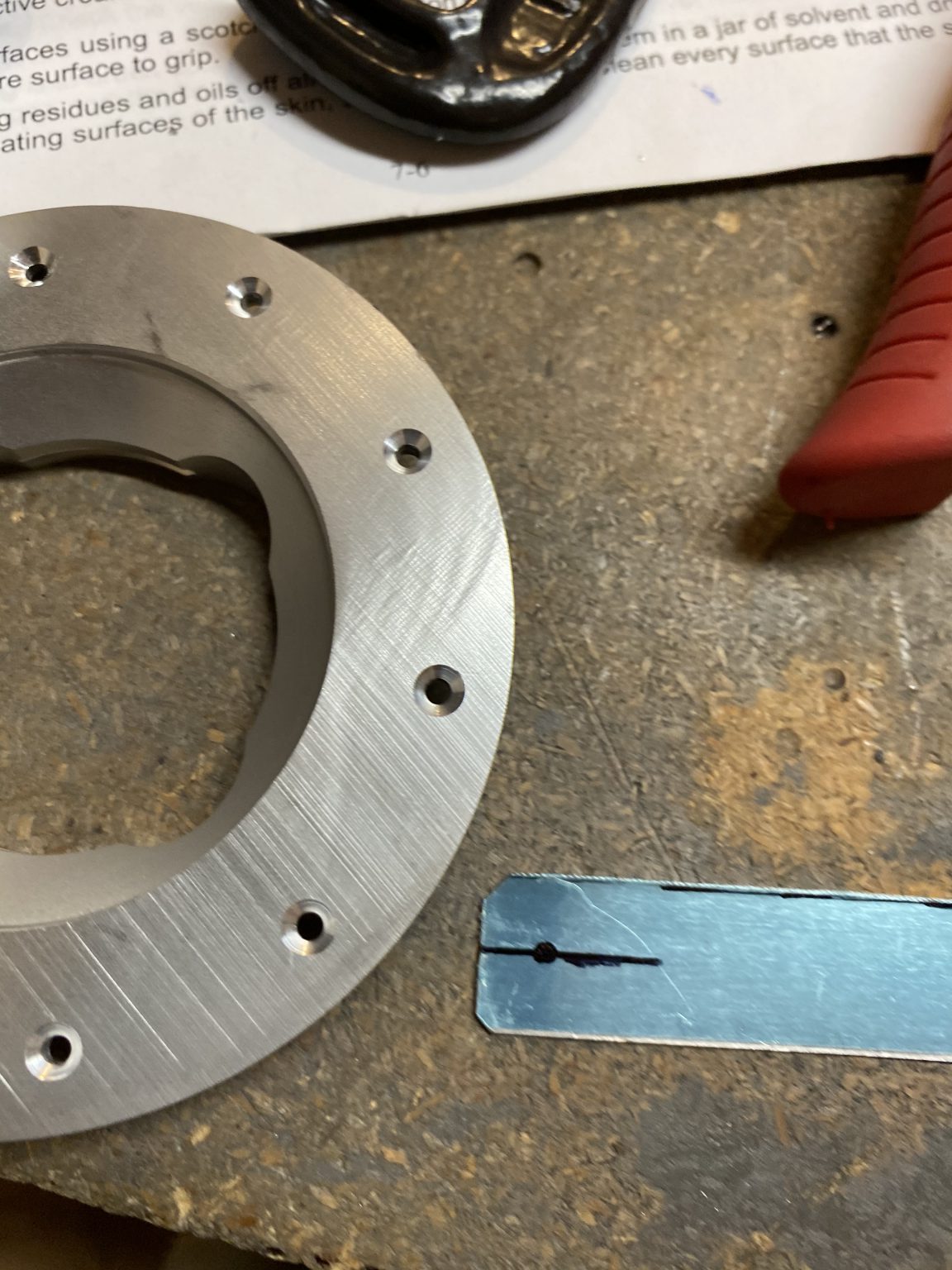
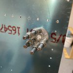
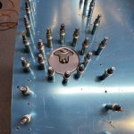
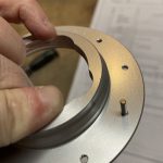
After I was happy with the alignment, I then started back drilling into the T-406B flange using the tank skins pre-punched holes as my guides. Like always, I’d drill a hole, then insert a cleco into that new hole to help hold everything tight before moving on to drilling the next hole. I only removed the clamps at the very last moment.

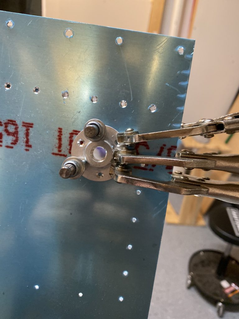
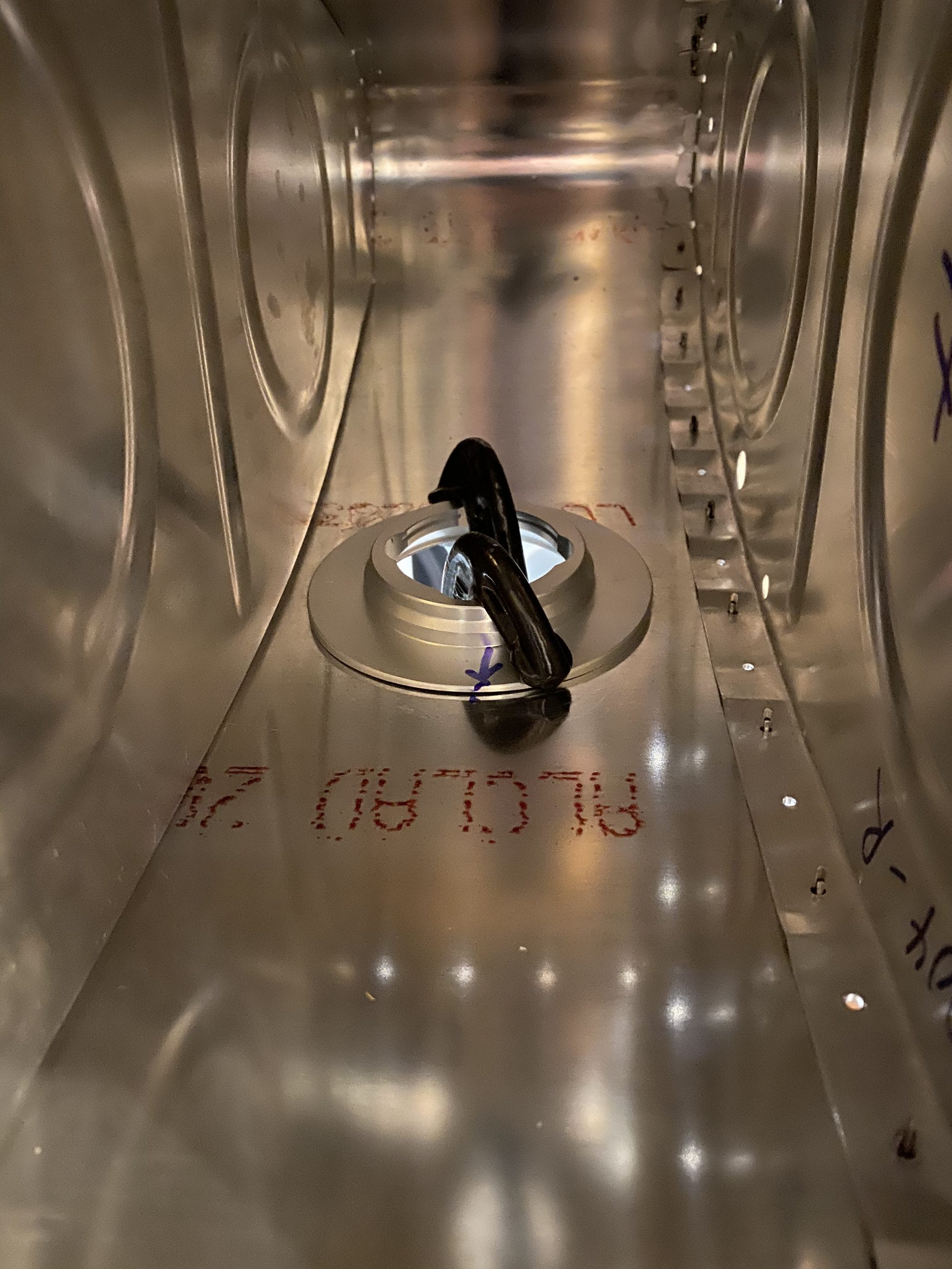
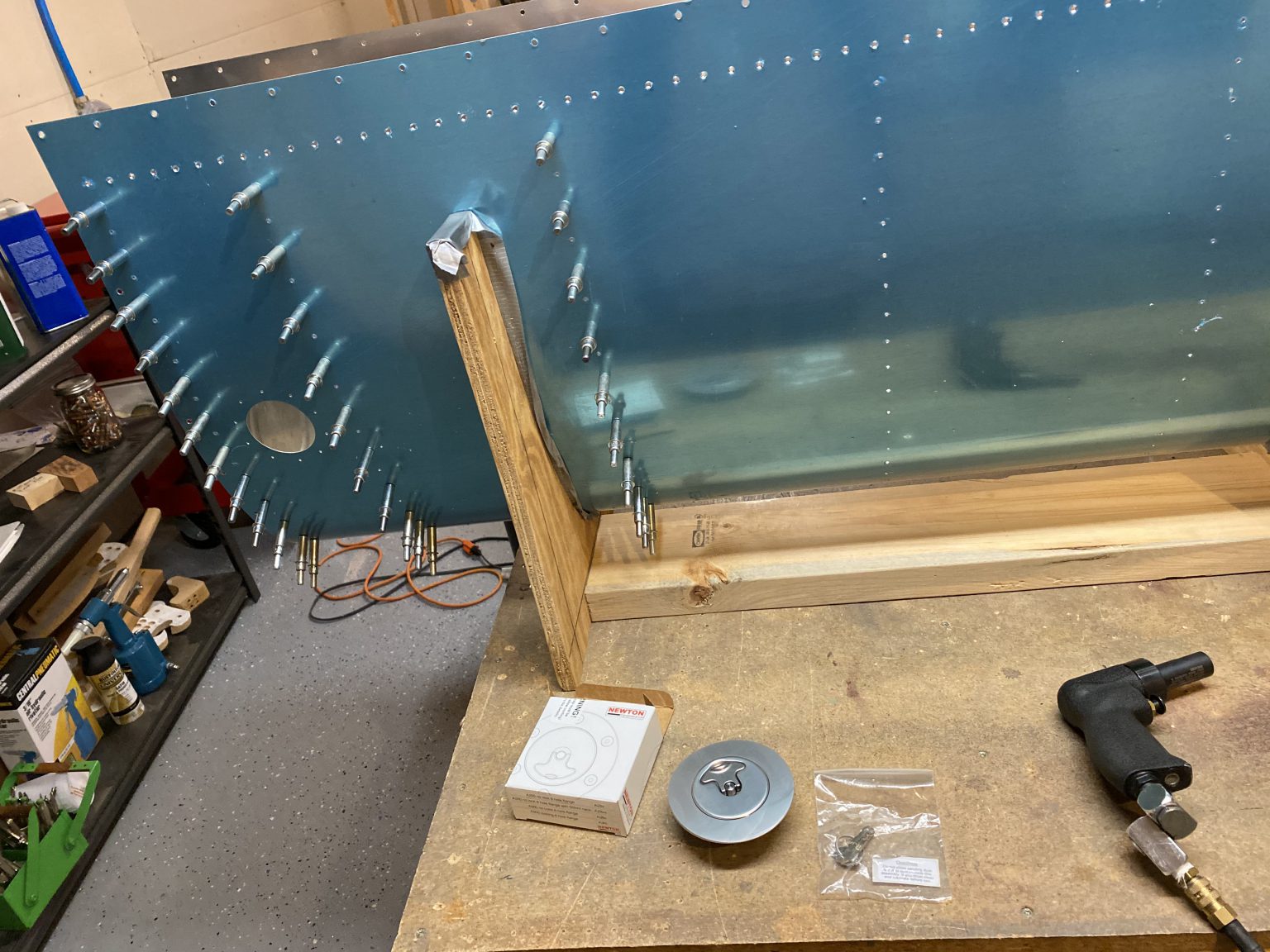
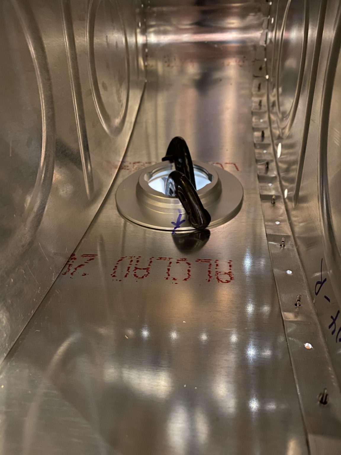
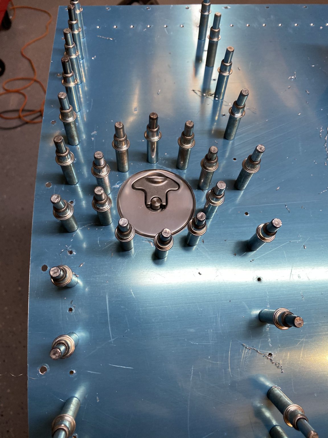
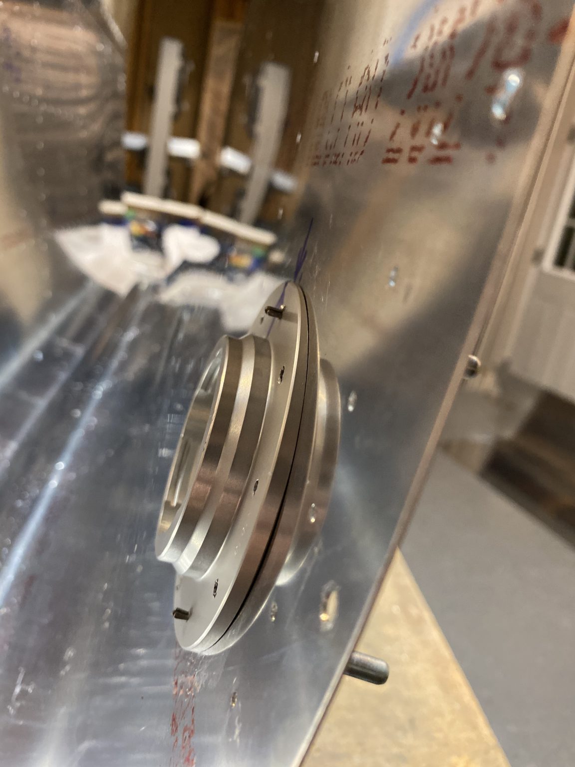
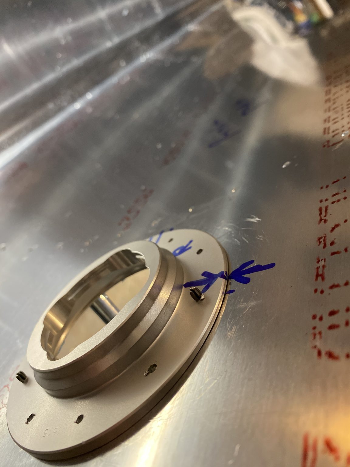
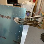
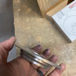
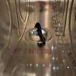
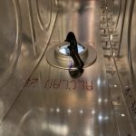
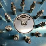
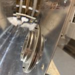
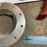
And VOILA! This his how it looks when its all said and done. I can’t tell you how good and how flush these fuel caps are! They are really sexy and are very well made. I’m also very happy with just how well sized the pre-punched filler hole was in the skins, as I didn’t need to do any sort of work on the skins hole to get everything lined up. It really made this look like a completely professional install.

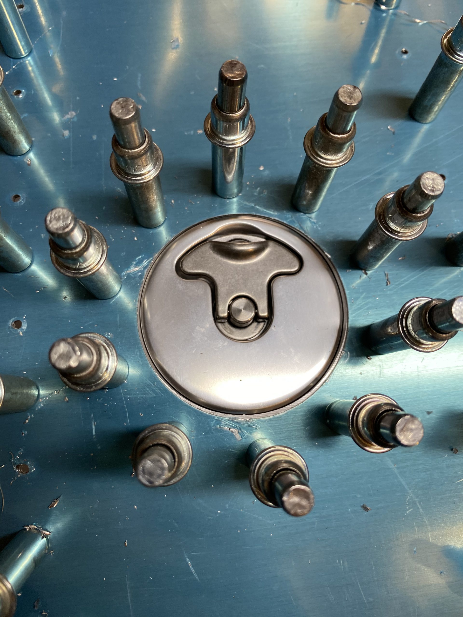


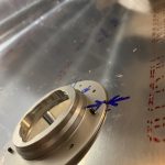
You can see how well the flange’s machine curve fits against the skin! I also marked the flanges against the skins so I could get them returned to their correct orientation when it comes time to rivet them on.

And here’s a quick little video of how well they look and work:
Once I had all the holes back drilled into the flange, I went ahead and deburred the new holes in the flanges, and then used my micro stop countersink to countersink the holes in the TOP part of the flange so they could receive the dimples that will be going into the tanks skin. I adjusted the countersink so that it would do a little deeper into this part as its very thick, and I wanted to give plenty of room for the dimple in this .032″ tank skin, and also leave room for some proseal to goop in the dimples for sealing. Once I had one tanks fuel cap done, I did the same exact process on the others wings fuel tanks.

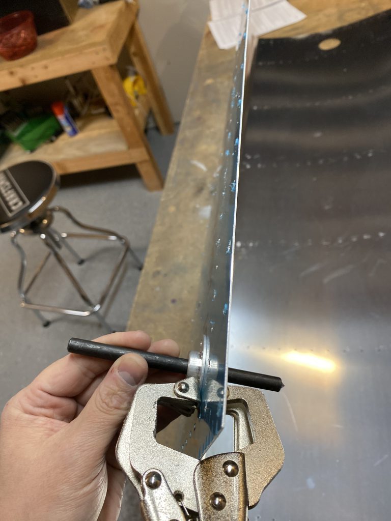
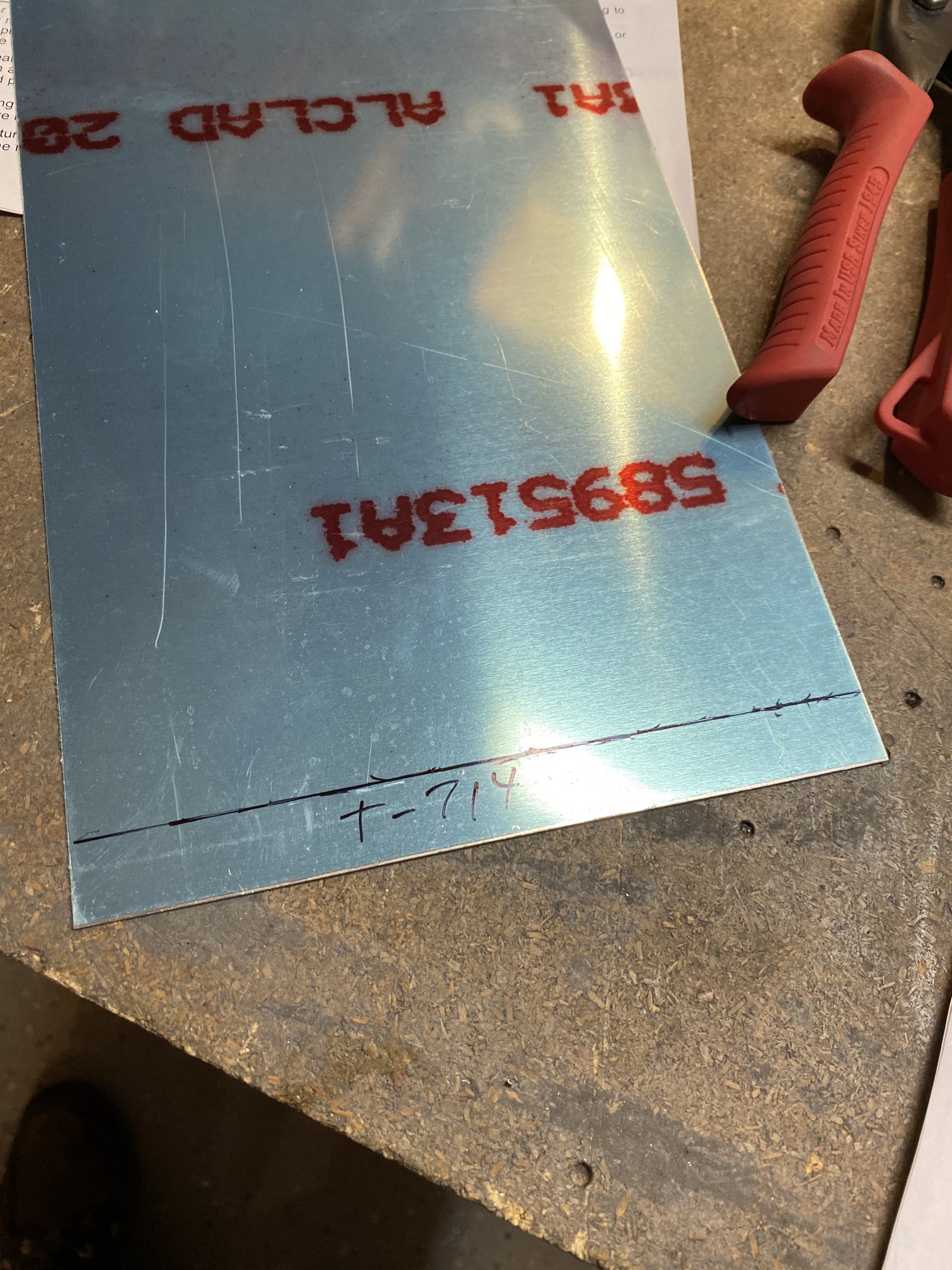
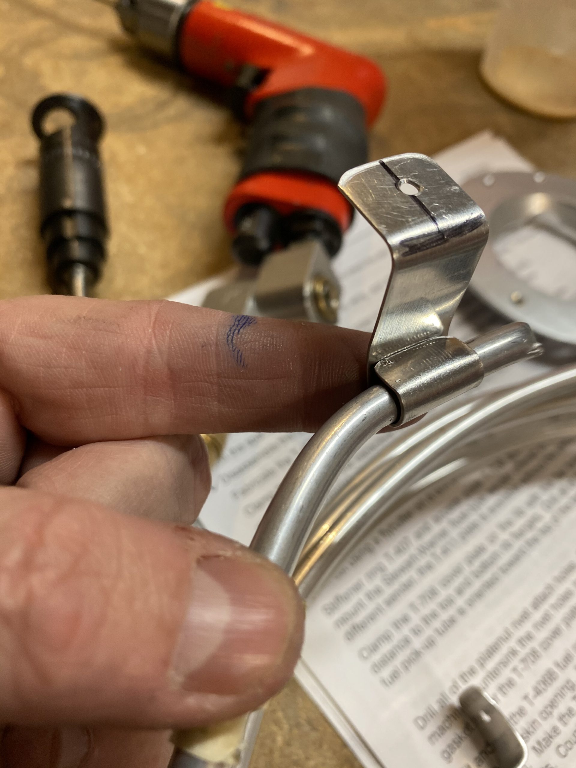
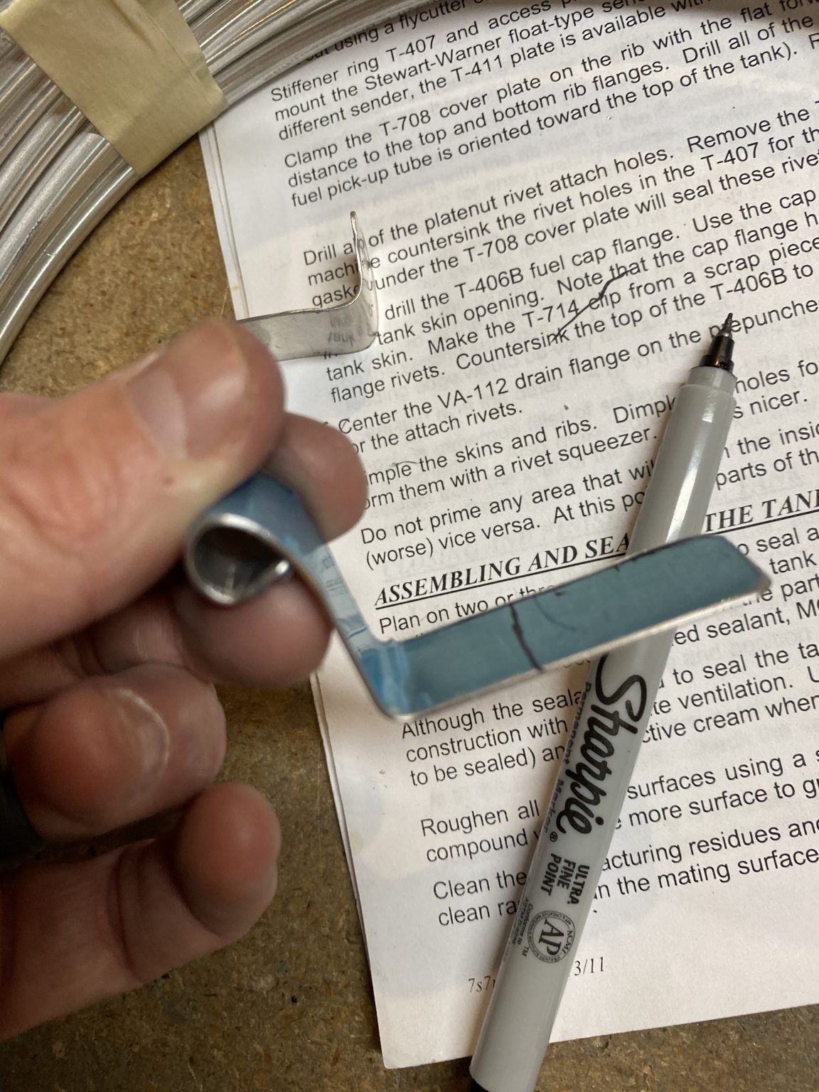
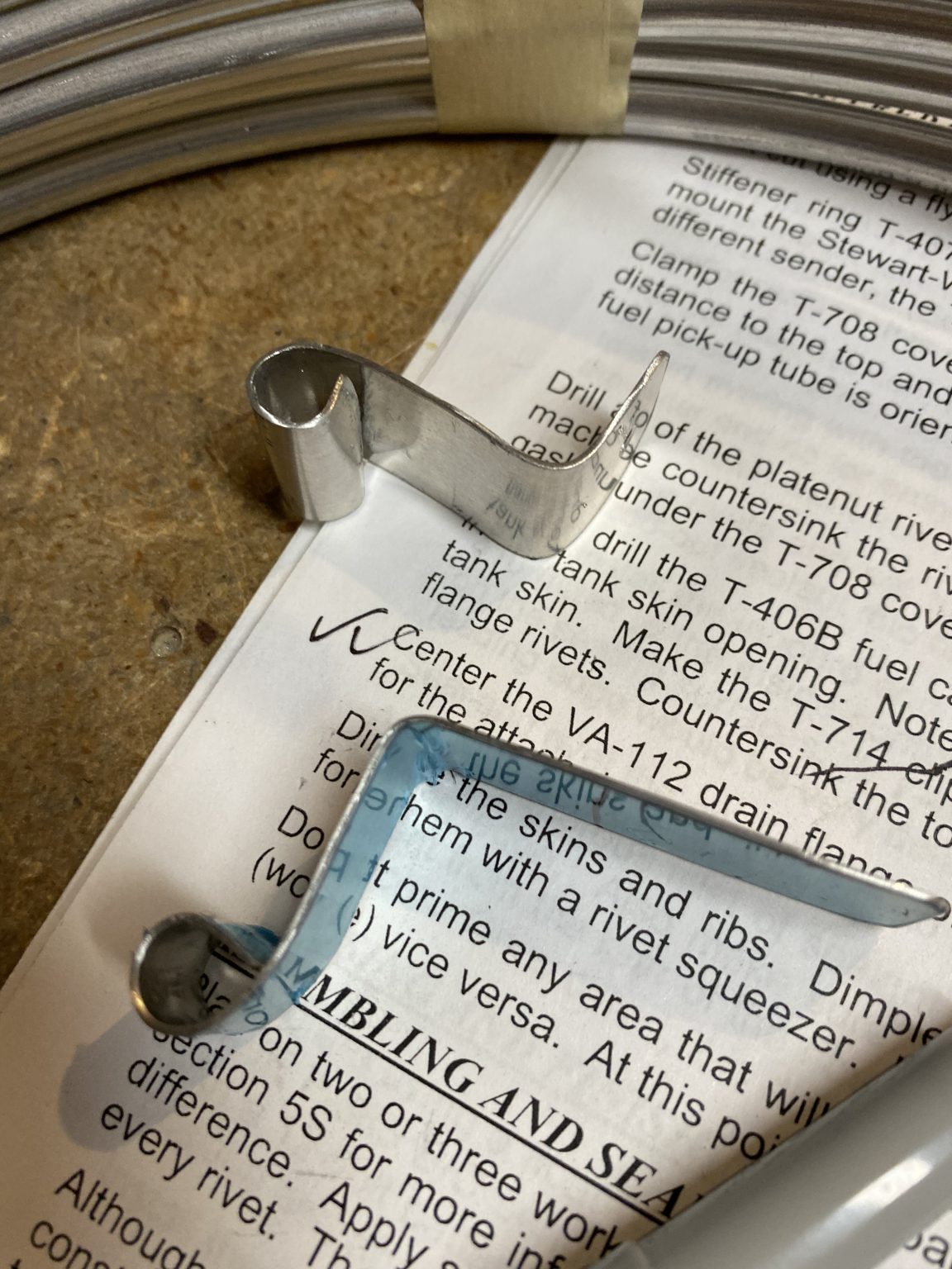
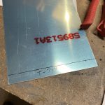
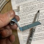
The last little step I enjoyed pretty well. I needed to fabricated the T-714 clip for the vent line out of some 0.025 x 1/2″ wide sheet. I dug in my scrap bucket, and found a nice sheet of alclad in 0.025, and marked out a 1/2″ wide strip along the edge, and then cut it off with my snips.
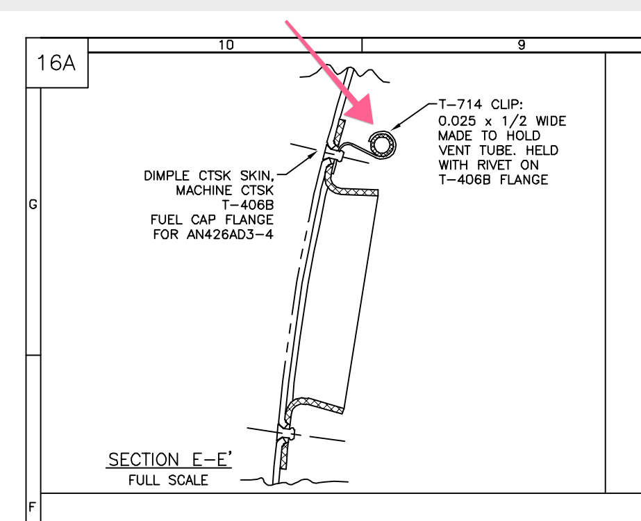
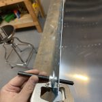
Once I had my strips cut, I had to form them into the shape that is denoted on the plans like this:
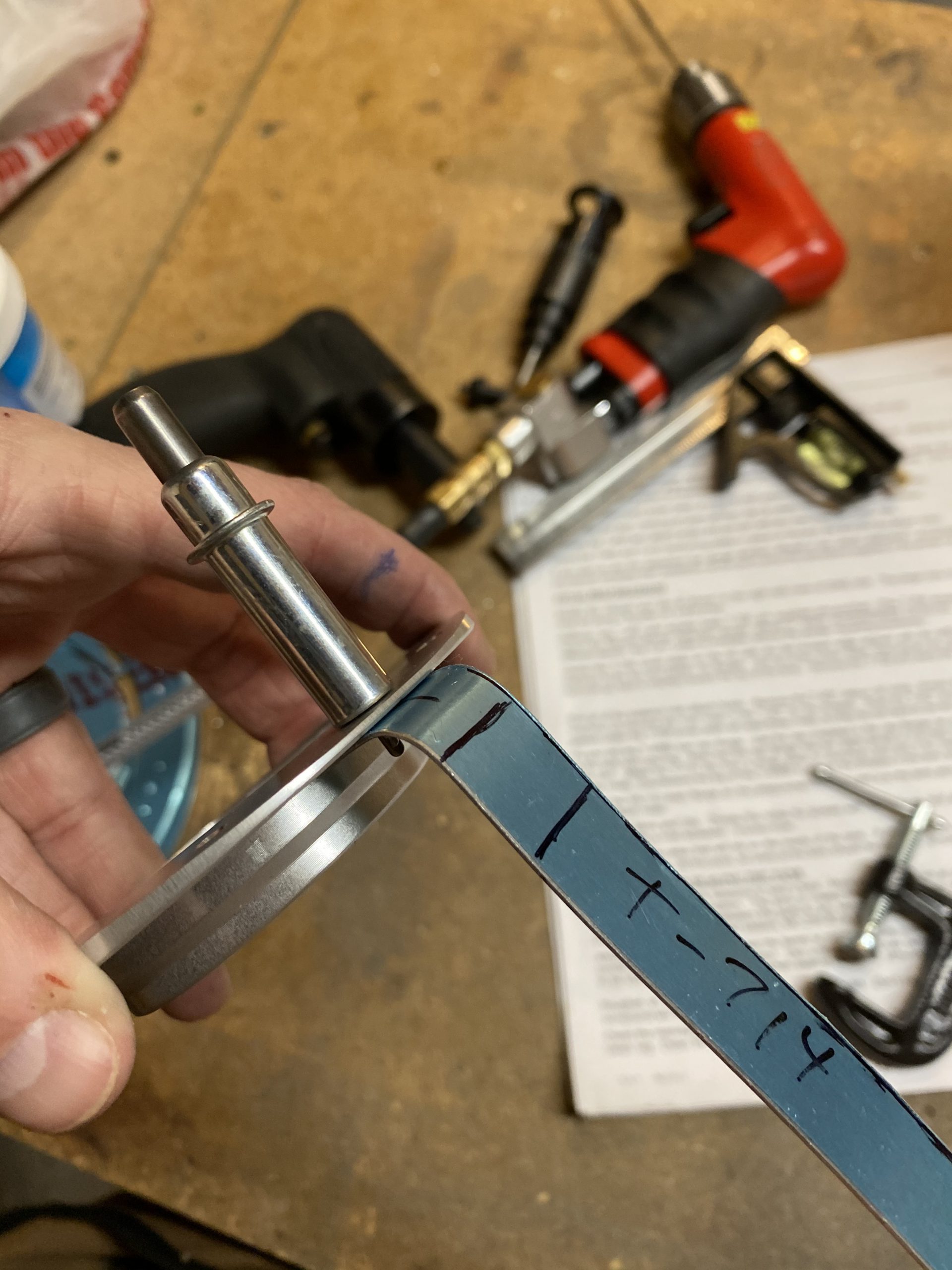
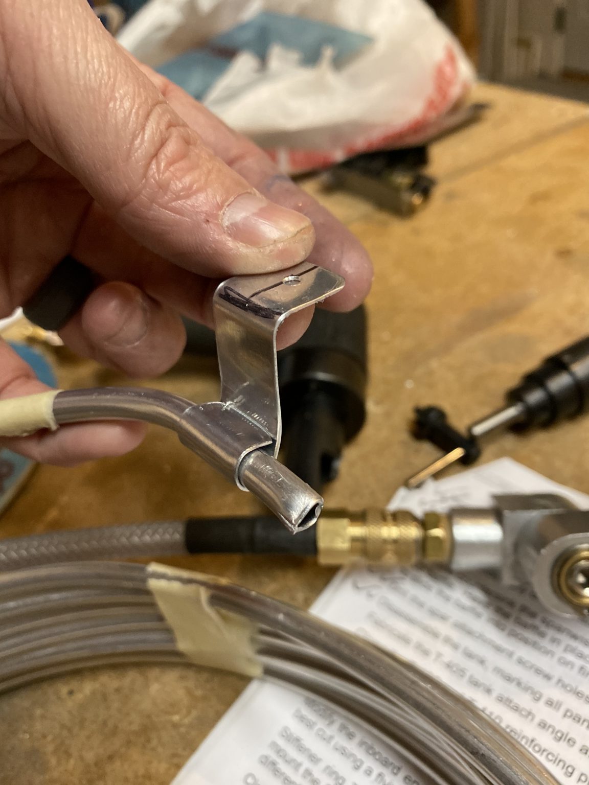
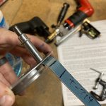
Next I marked a centerline on the strip so I could get the rivet hole just right, and then placed the centerline on the T-406B flange rivet hole to mark the hole onto the strip where I’d need to drill into it for its mounting hole. Then drilled it with a #40 drill bit to match the flange, and formed a rough bend line to get an idea of what I should do.

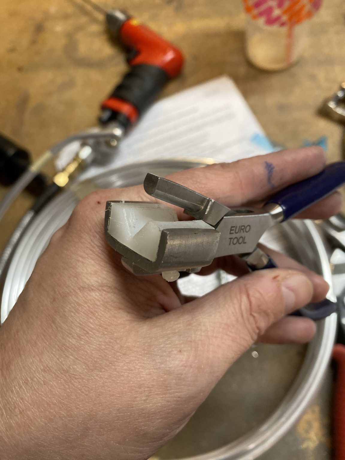
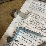
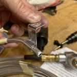
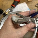
Before going to far, I deburred the edges using my bench grinder and then rounded all the corners to prevent any stress cracks. For the bends, and even for the loop in the clip, I used a handy set of forming pliers to get nice and straight bends.

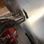
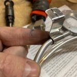
I then formed the loop in the T-714 clip using the aluminum tubing that will eventually be the vent line, as well as the forming pliers until I was happy I had a nice loop to hold the vent tubing.

Once I had one completed, I went ahead and done the other tank’s T-514 clip in the same manner, making sure to deburr the rivet hole and deburr the edges. These turned out better than I had expected, and I am a little proud of how they ended up looking! Too bad they’ll be in the tanks where no one will ever see them. Hah! That was enough for tonight. That completed the cap and drain system for the tanks. I still have a little more fabricating to do on some other tank parts, but thats for another session! Here’s all the photos from tonights work:
-
 IMG_0579
 -
 IMG_0580
 -
 IMG_0578
 -
 IMG_0581
 -
 IMG_0582
 -
 IMG_0583
 -
 IMG_0584
 -
 IMG_0585
 -
 IMG_0586
 -
 IMG_0587
 -
 IMG_0588
 -
 IMG_0589
 -
 IMG_0590
 -
 IMG_0591
 -
 IMG_0592
 -
 IMG_0593
 -
 IMG_0594
 -
 IMG_0595
 -
 IMG_0596
 -
 IMG_0597
 -
 IMG_0598
 -
 IMG_0600
 -
 IMG_0601
 -
 IMG_0602
 -
 IMG_0603
 -
 IMG_0604
 -
 IMG_0605
 -
 IMG_0606
 -
 IMG_0607
 -
 IMG_0608
 -
 IMG_0609
 -
 IMG_0610
 -
 IMG_0611
 -
 IMG_0612
Google Photos Link: https://photos.app.goo.gl/QACsSYvKd9Rra7877
Hours Worked: 3.5