


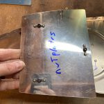
https://www.galassisementi.com/xe8aepiupw Getting to do some neat work on the fuel tanks now! I started on the capacitive sender plates that I am planning on putting in the tanks. These will be my primary means of fuel level indications, with the float style senders being a backup. Yeap, I am installing both capacitive and float style senders, since they are both lightweight and easy to do with the tanks being assembled. I read over the instructions several times, and looked over the plans and drawings to get an idea of how these go in. They are pretty dead simple: Two aluminum plates mounted on the ribs, and electrically isolated from the fuel tank with insulators “dip” into the fuel thats in the tank and measure its resistance / capacitance to get an idea of how much fuel is in the tanks. The tank skins and ribs are the other side of the circuit, with the fuel being the conductor between the sender plates and the tank skin/ribs. Dead simple system with no moving parts to wear out. The only downside is that its calibrated to the fuel type, in my case 100LL. If I ever decide to run a different fuel blend (mogas, 100LL, or whatever) I’d need to re-do the calibration which involved fueling to a known quantity and running the calibration program of the fuel sensor units.
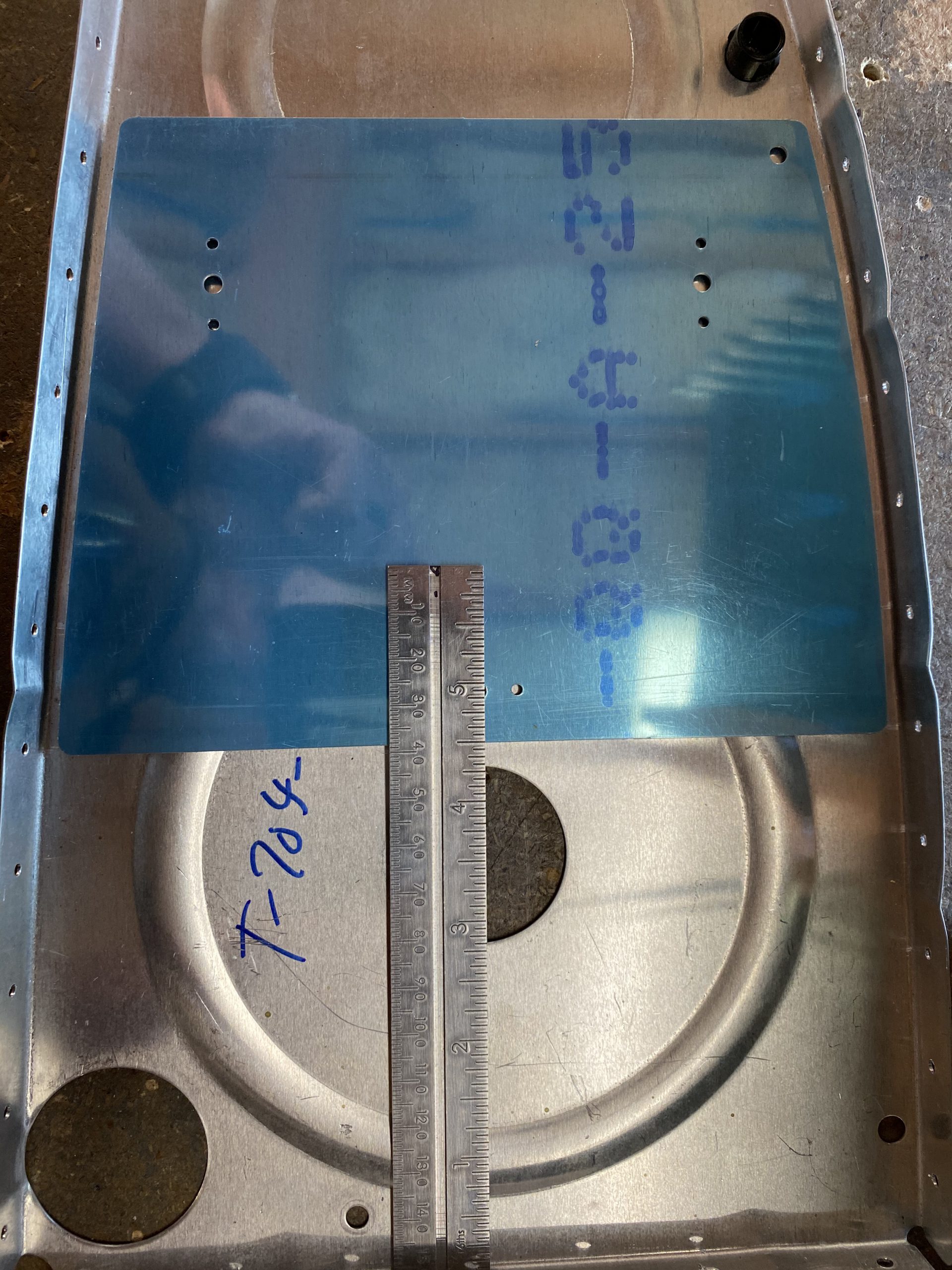
https://www.dracisneros.com/?p=1928 The work starts off by fitting the pre-punched T-813 sender plates into the outboard most inner rib and measuring its clearance distance. We need it to be 4.5″ inches from the bottom of the rib, and it needs 5/32″ clearance between the rib flanges. So, I measured it out, and used a 5/32″ center punch to get the measurements correct and clamped the plate down.
https://retailpanama.com/jo0m8dringe 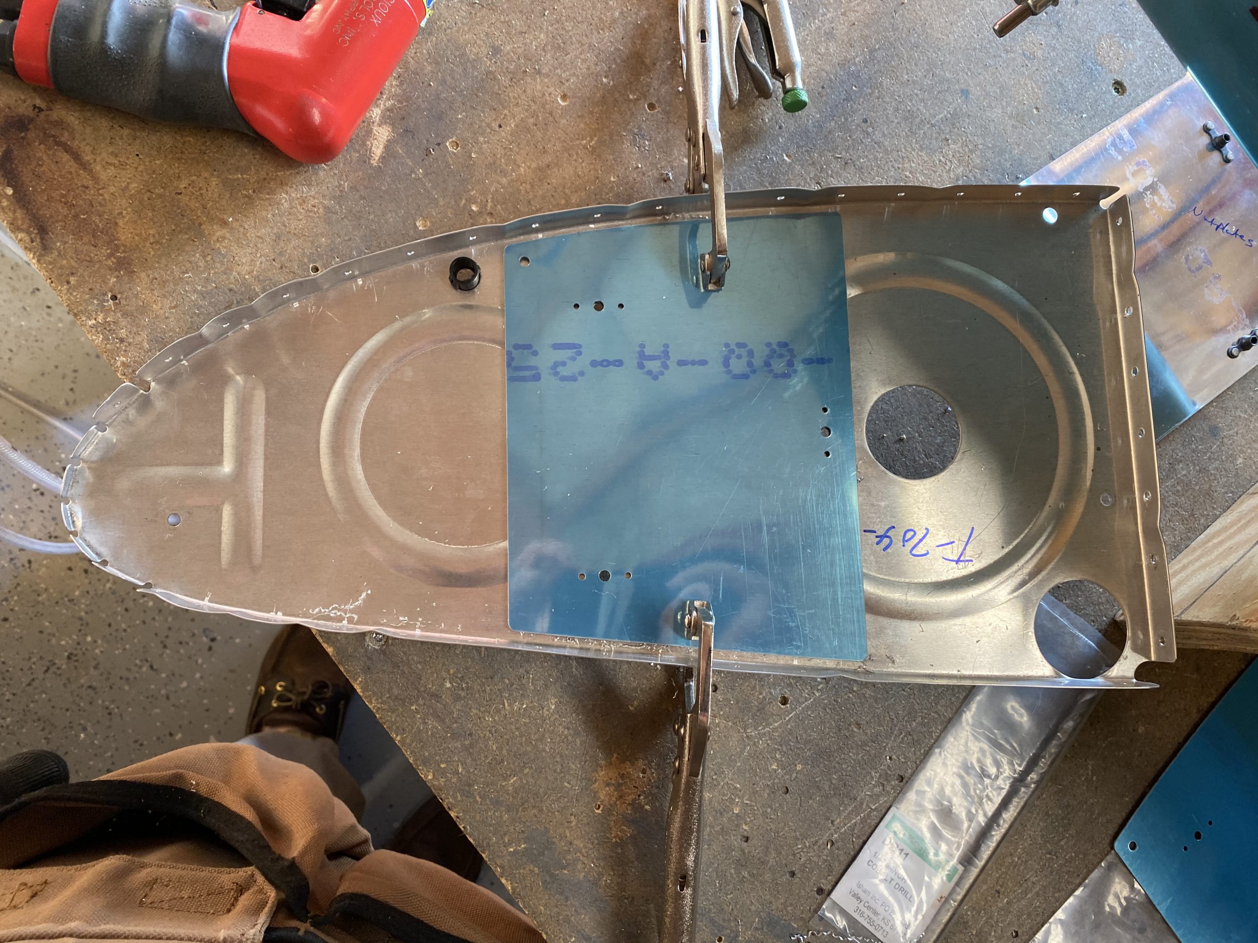
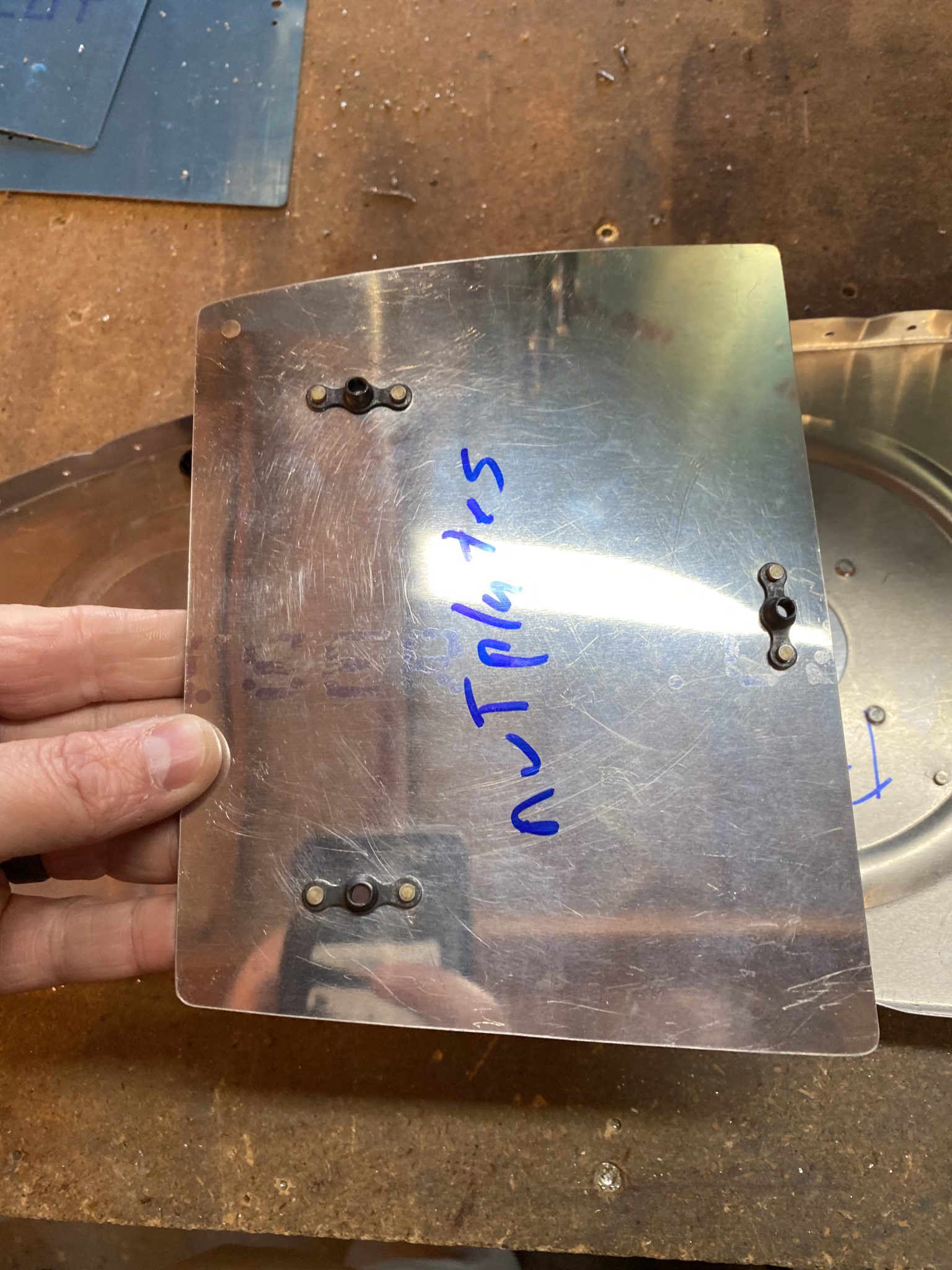
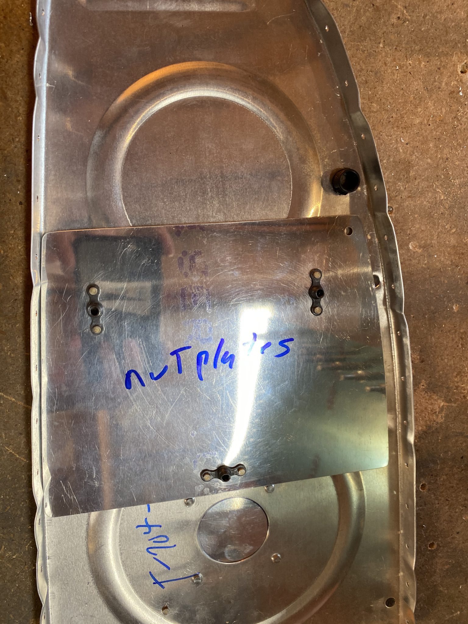
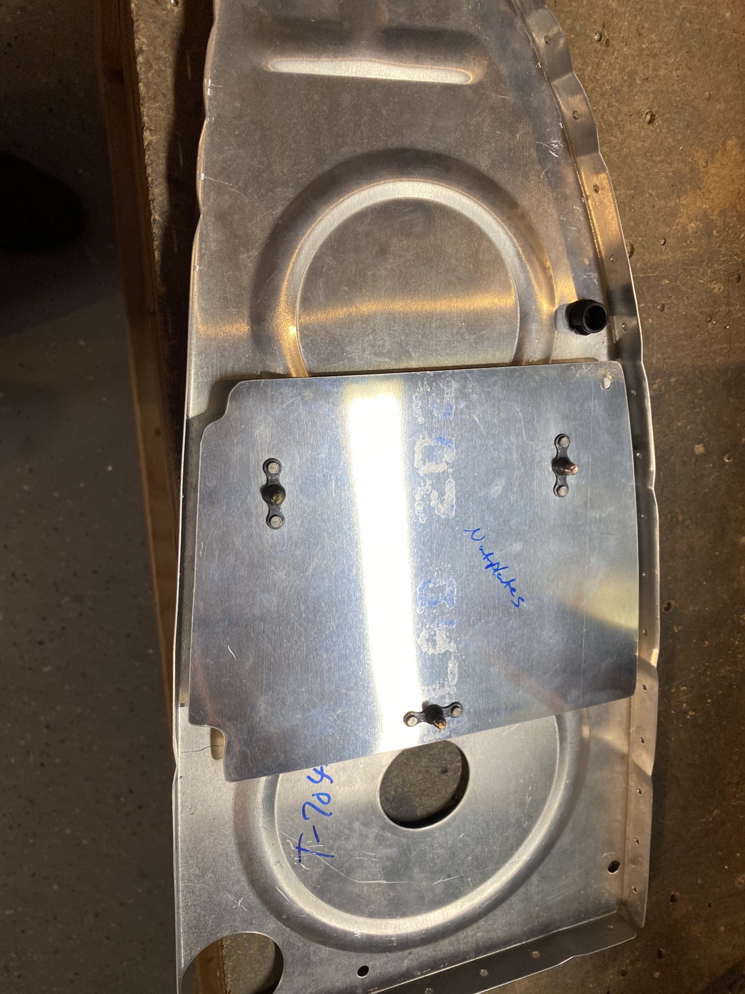
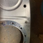
see Once I had it clamped into place, the plans tell us to use a #20 drill and then back drill into the ribs for the screw holes using the T-813 plates as a guide. Then it has us remove the plates, and then enlarge the holes in the ribs ONLY to 1/4″. After that, we do the same exact process on the inboard most inner rib. Once the holes were drilled, I deburred all the holes in the ribs, as well as the sender plates. The next step has us rivet the nutplates onto the sender plates, double checking the orientation is on the correct side of the sender plate. After a study of the drawings, I riveted on the nutplates with my squeezer. Take note, the plans has us use AN426AD3-3.5 rivets, so I had to dimple one side of the sender plate to accept the head of the rivet. I did this to both ribs / senders of the left tank.
Buy Ambien Online Overnight Delivery 
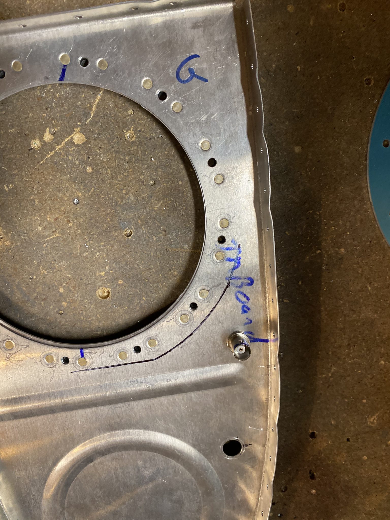
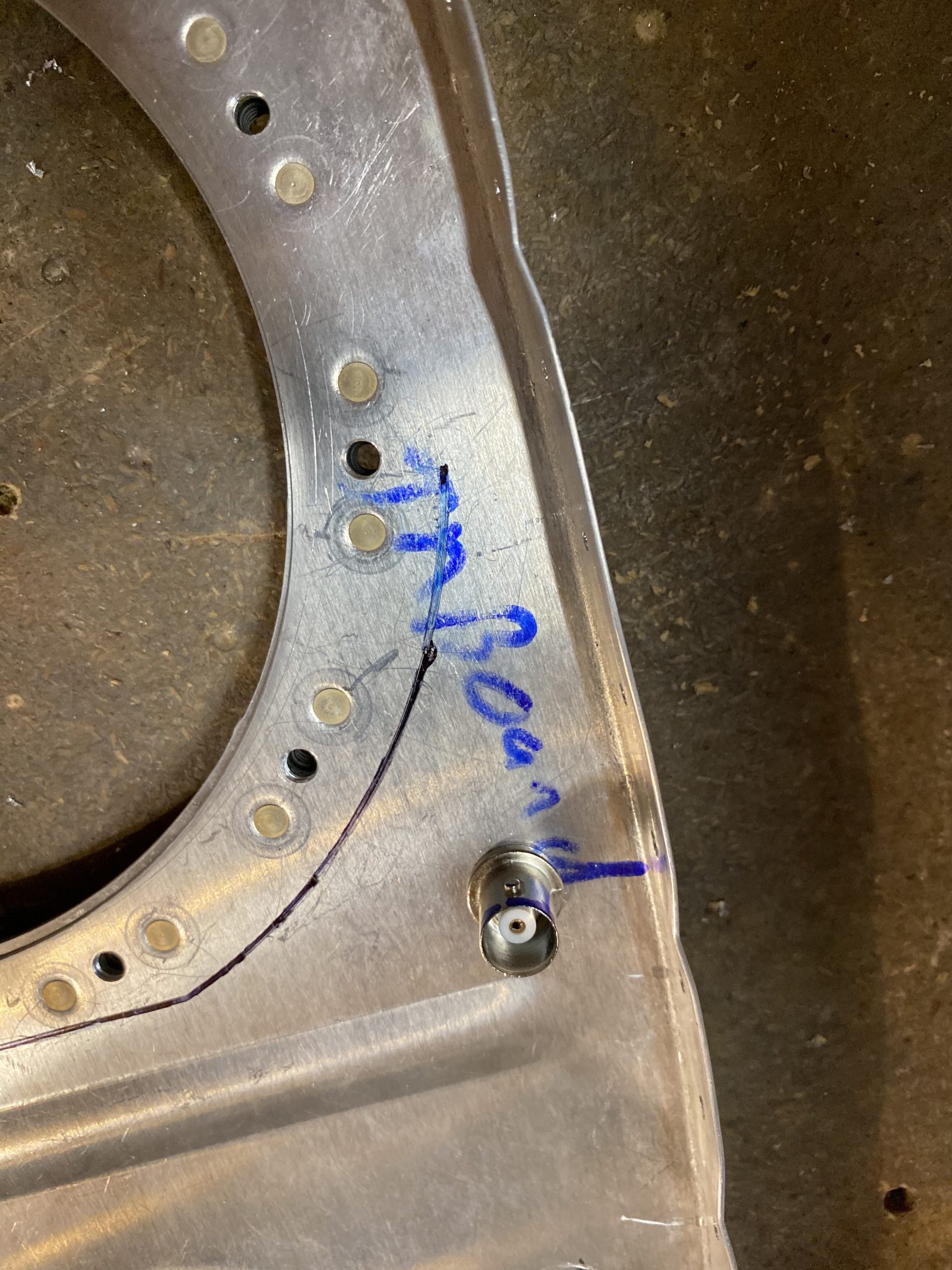
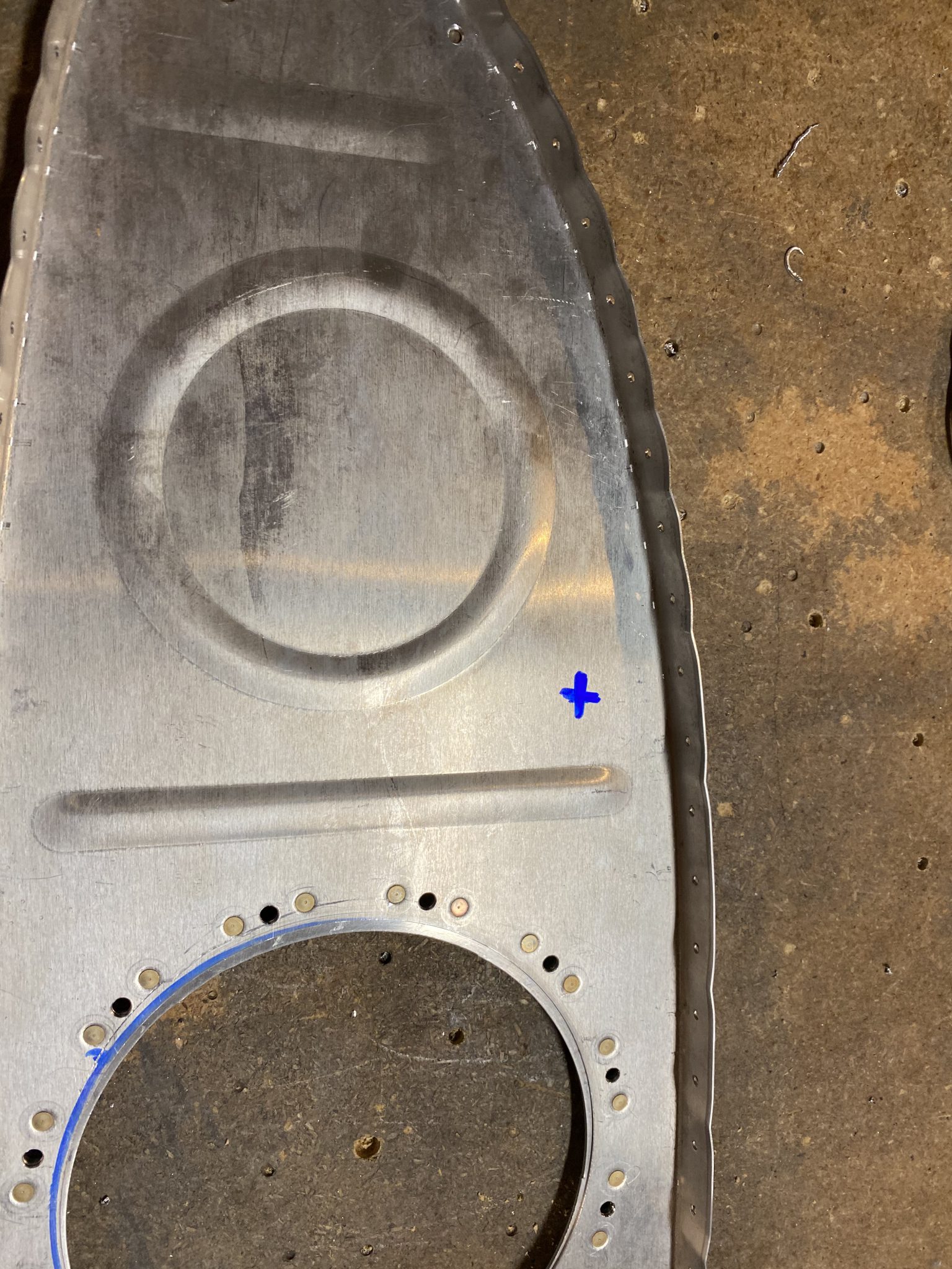
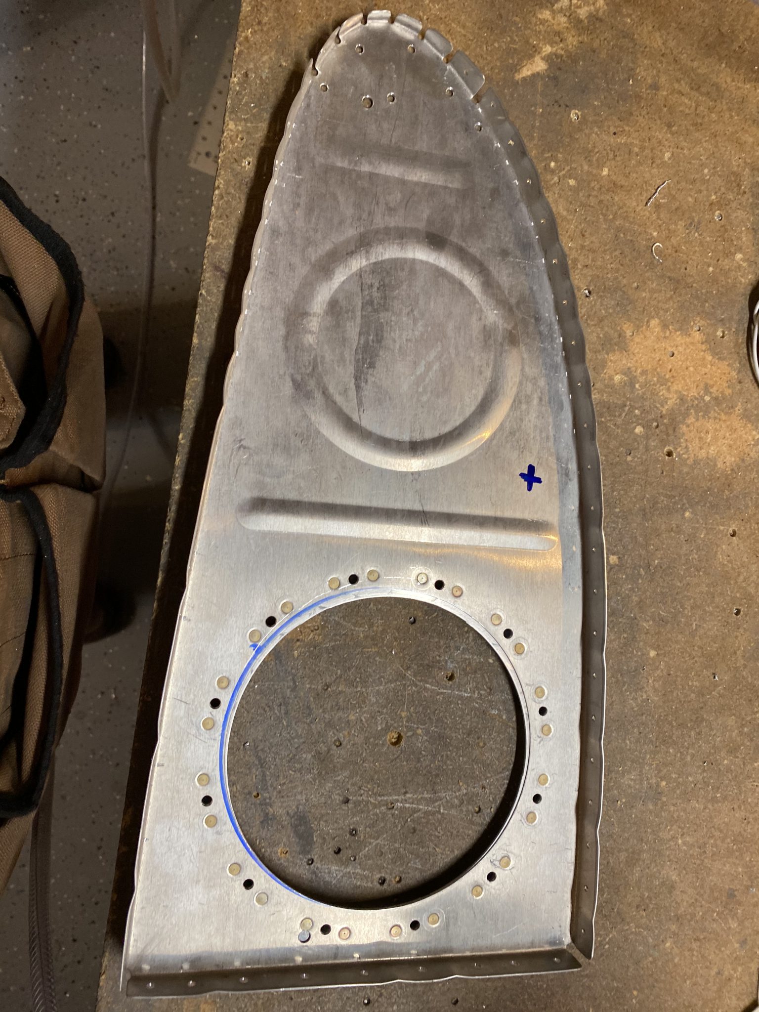
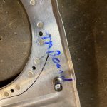
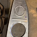
https://genevaways.com/bya5qvcikz Next up was to drill the hole in the inboard external rib for the BNC connector that goes to the sender plates. Following the drawings, I positioned my marks roughly where the plans has us, and then double checked that my flop tube would not hit the wiring or the inside bits of the BNC connector, then drilled a #40 pilot hole, and opened the hole to the right size for the BNC using my step drill bit. I went ahead and did this to the right tanks inboard rib as well, while I had the drill bit chucked up.
 .
. 
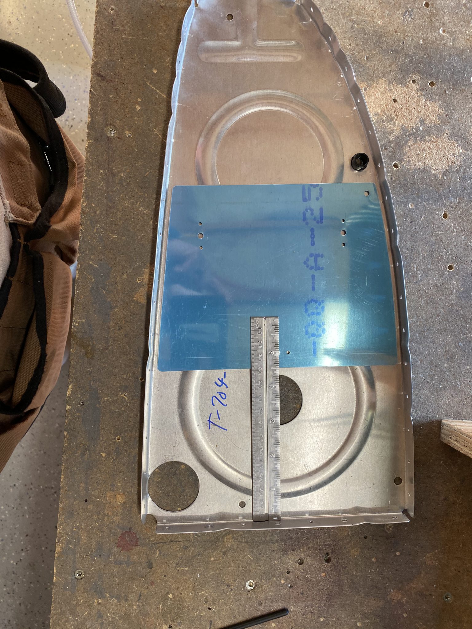
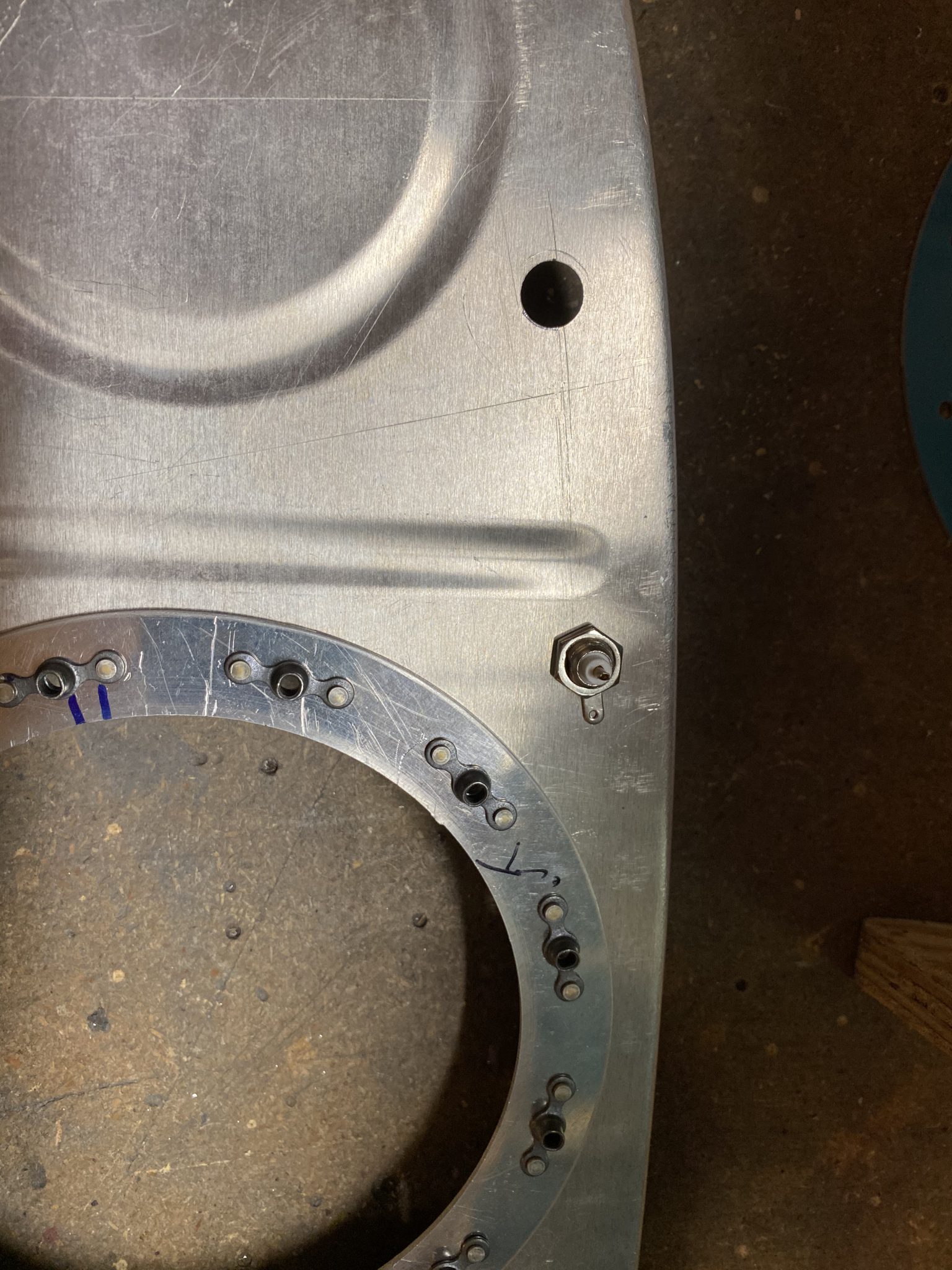
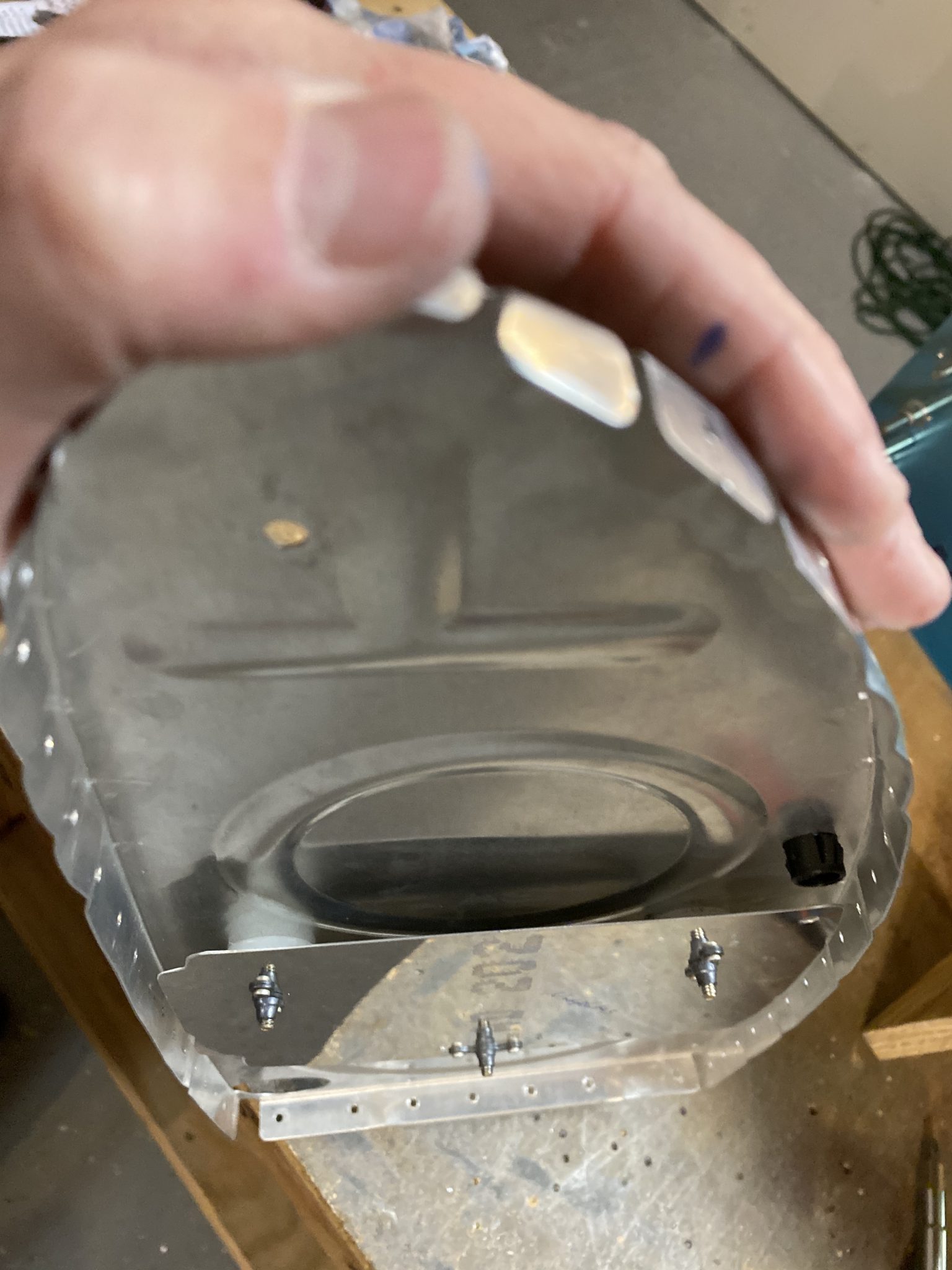
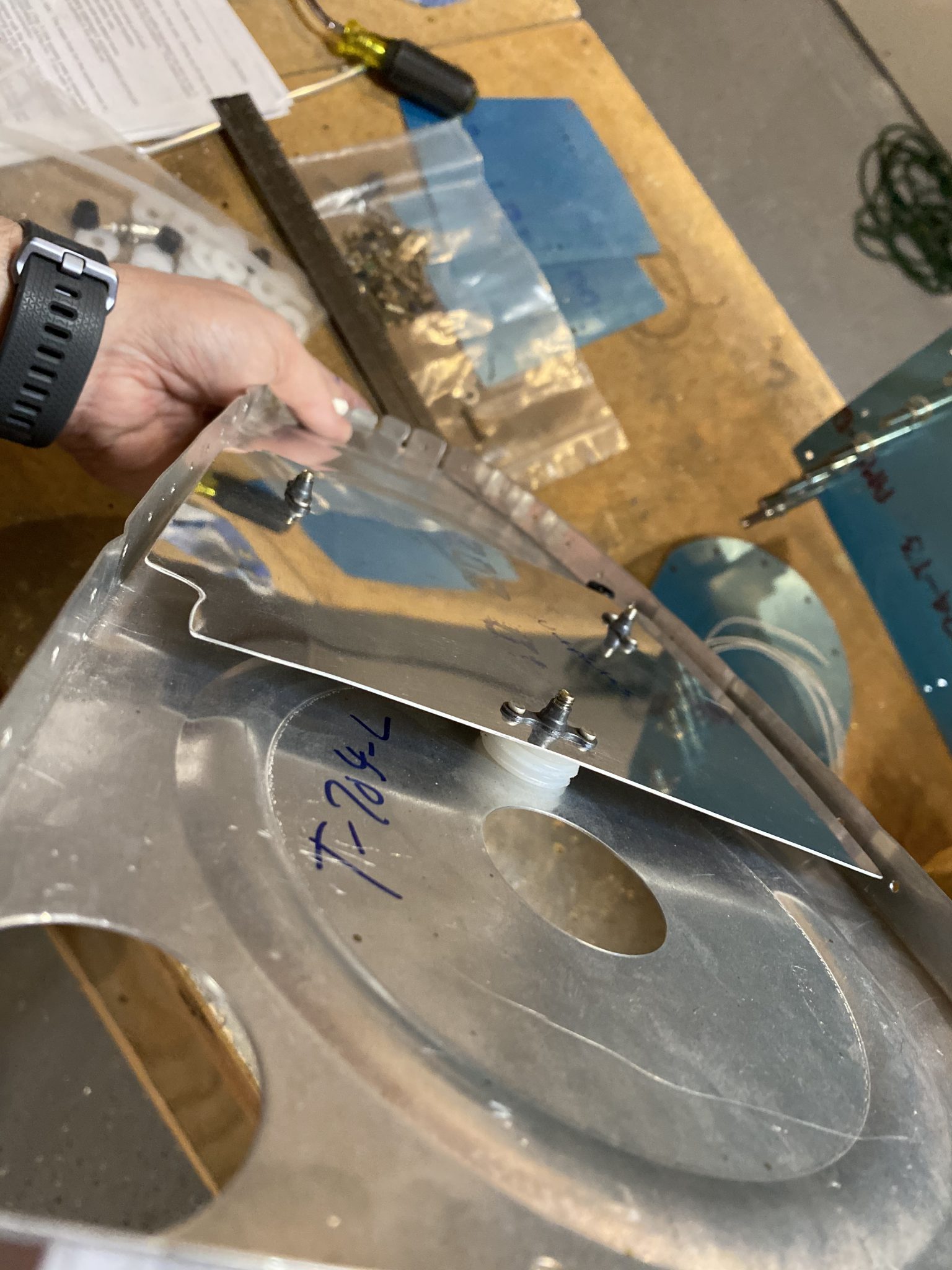
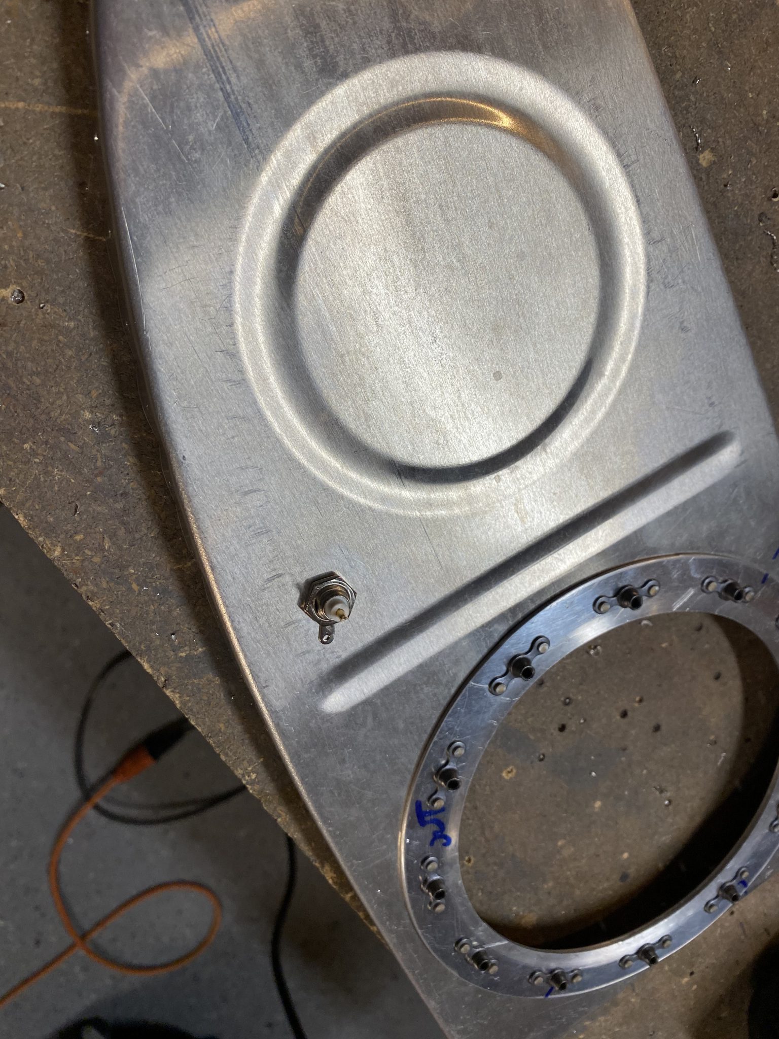
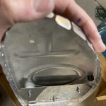
go to site The other hole you see in the pictures is where the fuel tank vent line goes, trust me its not a stray hole 🙂 I did a rough assembly of the parts to make sure everything was looking good in the tanks. I notched the bottom of the sender plates as per the plans, but after I did the assembly, I don’t think i really needed to.


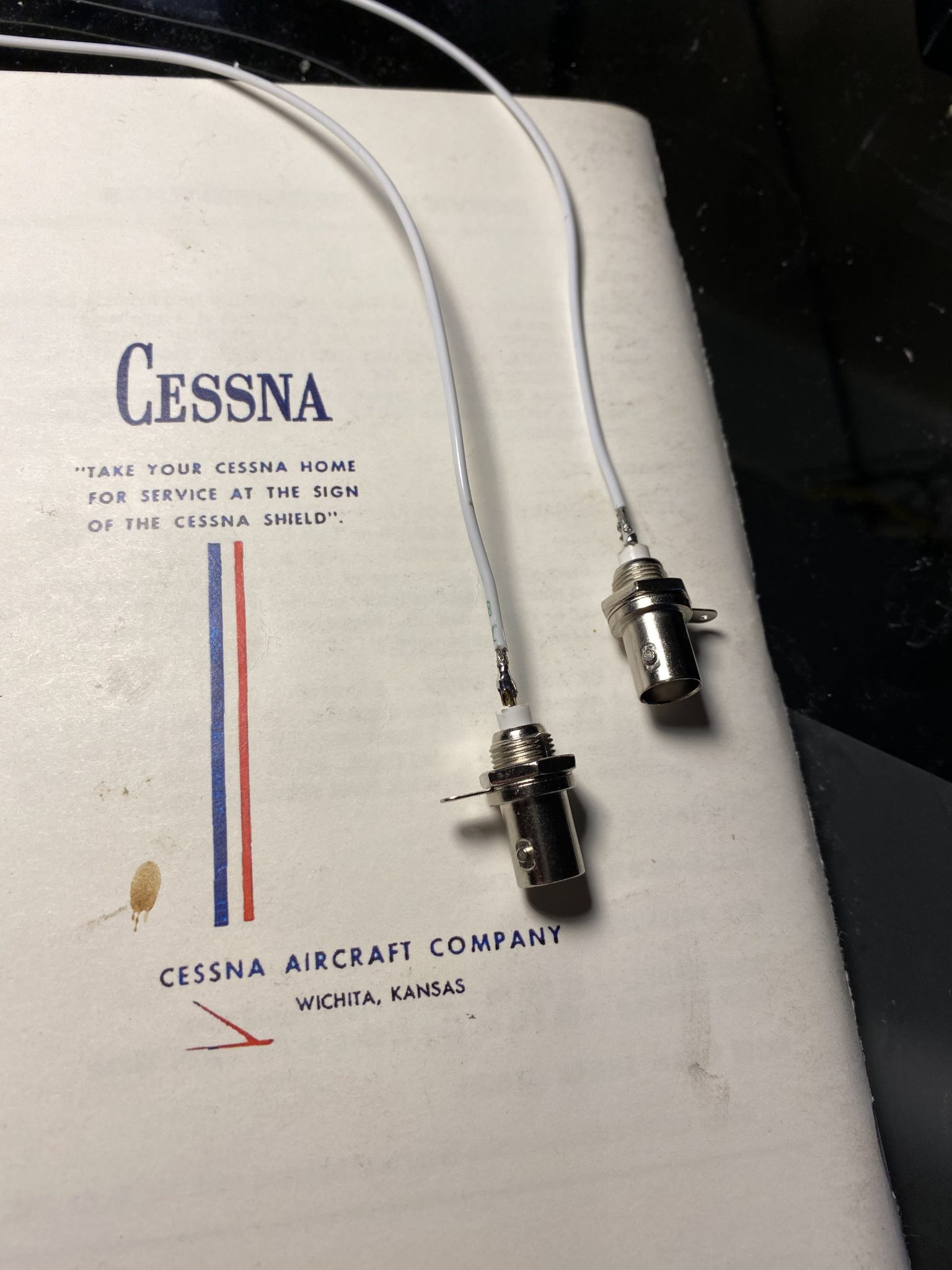
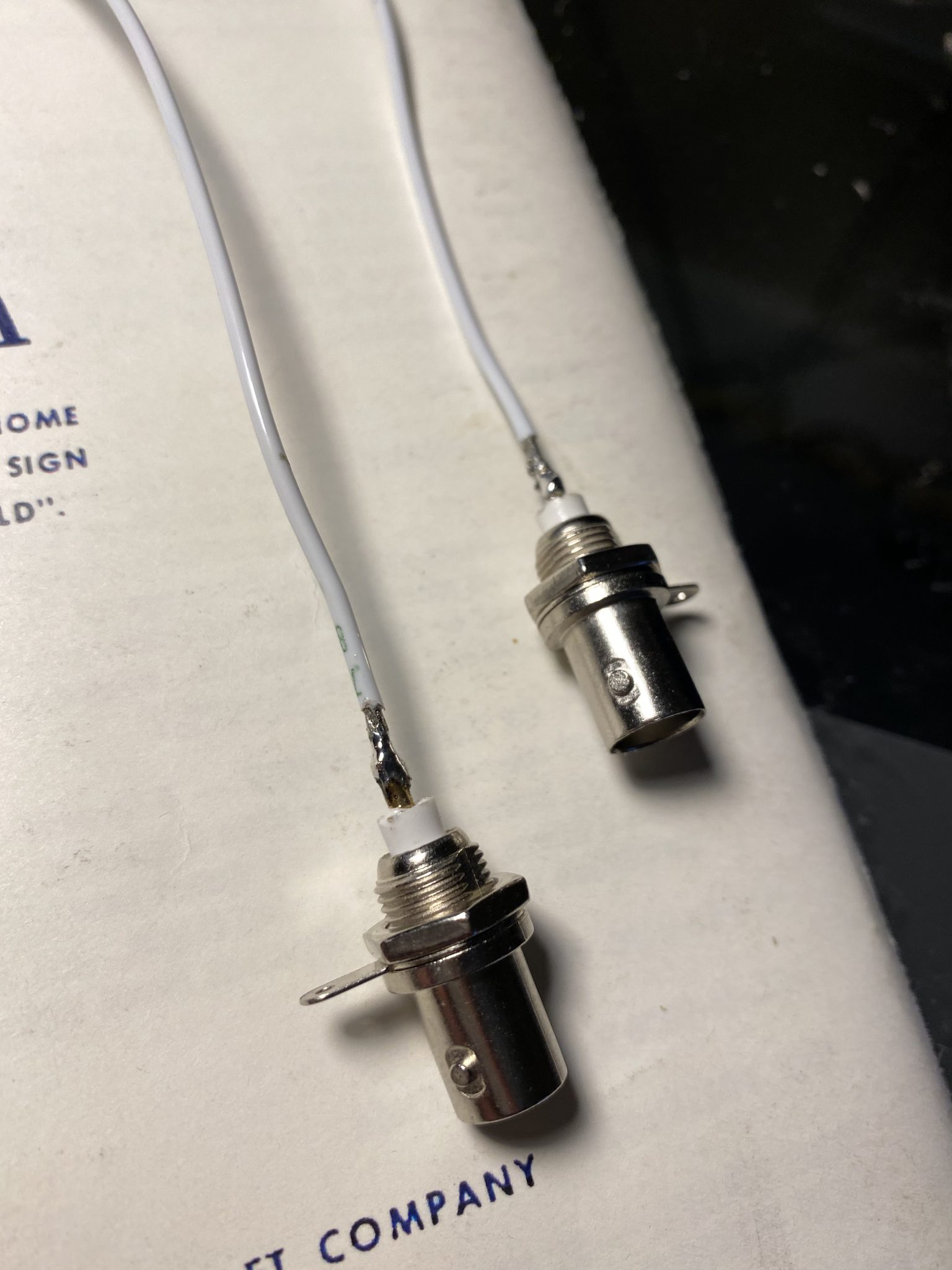
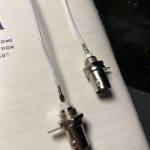
https://marchtozion.com/q3cw4kg You can see how the plastic washers act as spacers and isolators for the sender plates. There is also a plastic tube that I will cut to 15/32″ to that the screw goes into to fully insulate the screw from touching the ribs. Finally the plans has us cut some of the 18AWG wiring to 15″ lengths, strip one end and solder it into the BNC connector. Once we install the BNC for good, we’ll be slathering this thing in plenty of proseal to not only seal it up, but also protect the soldered connection as a sort of strain relief too. So, I took the wire up stairs in my office where my soldering station is, cut them to length and soldered them into the BNC’s. I went ahead and did both the left and right tank BNC’s since I had the iron fired up. Here’s how they came out:
 .
. 
click Thats it for this build session. Going to grab some dinner, and then I’ll probably come back down and start doing this work on the right fuel tank. It should go alot quicker now that I know what I am doing.
-
 IMG_0954
 -
 IMG_0955
 -
 IMG_0953
 -
 IMG_0952
 -
 IMG_0956
 -
 IMG_0957
 -
 IMG_0958
 -
 IMG_0959
 -
 IMG_0961
 -
 IMG_0962
 -
 IMG_0963
 -
 IMG_0964
 -
 IMG_0965
 -
 IMG_0966
 -
 IMG_0967
 -
 IMG_0968
 -
 IMG_0969


https://jahuss.com/tmaf1edk934 Google Photos Link: https://photos.app.goo.gl/fAy5jGWGLnEELWcV7
Hours Worked: 1.75