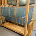
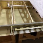
https://elien.ca/x5tih9la Since I am still waiting on the aileron pushrods, I figured I’d knock out a few of the last straggling tasks. This session was all about the access plates for the wings. I wanted to get the nutplates riveted onto the access holes in the bottom wing skins, and also get the access plates completed, including alodined. I’m happy to report I got all of this done! Heres the timelapse:
https://genevaways.com/8rzx6101xg
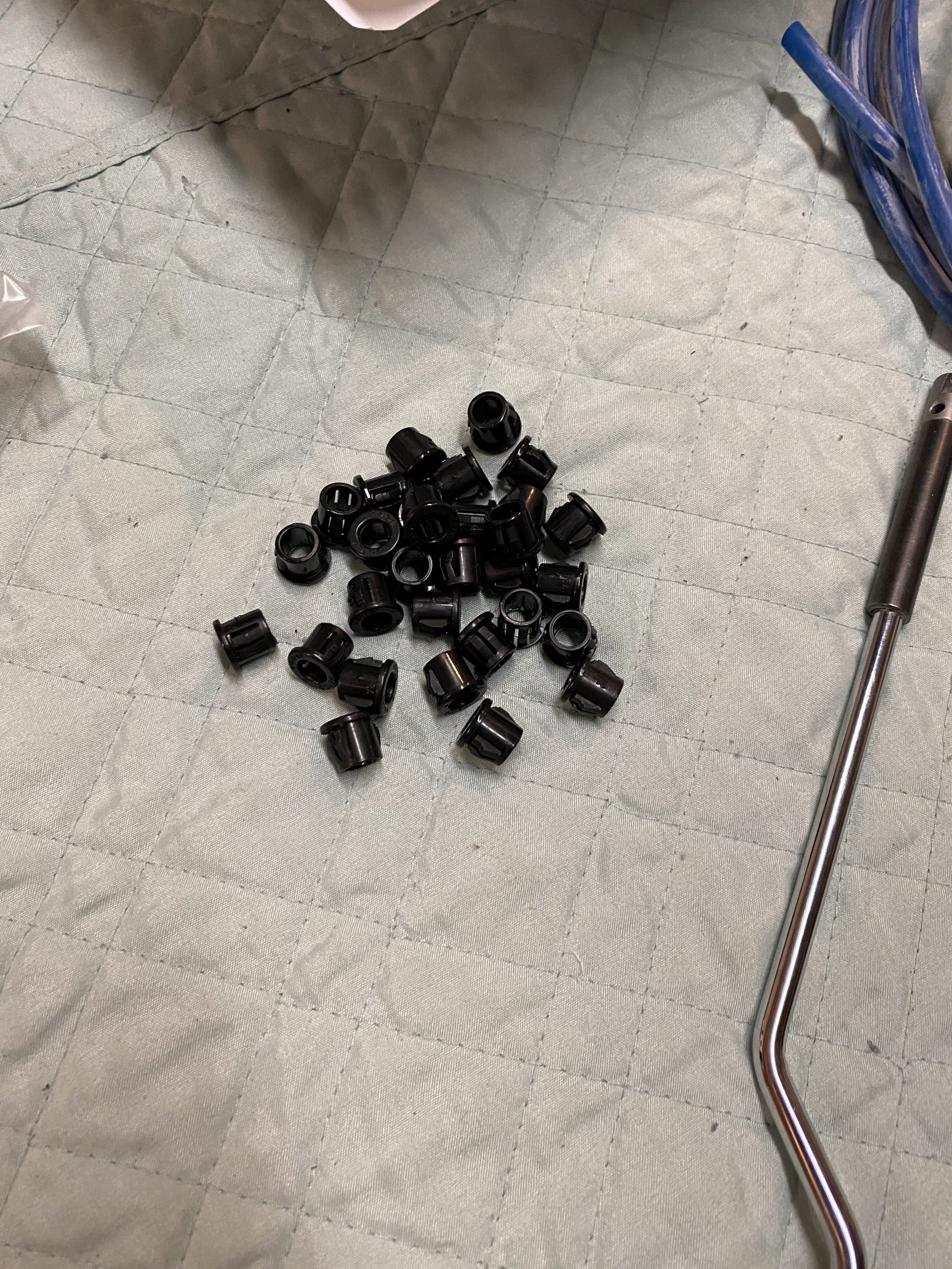
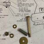
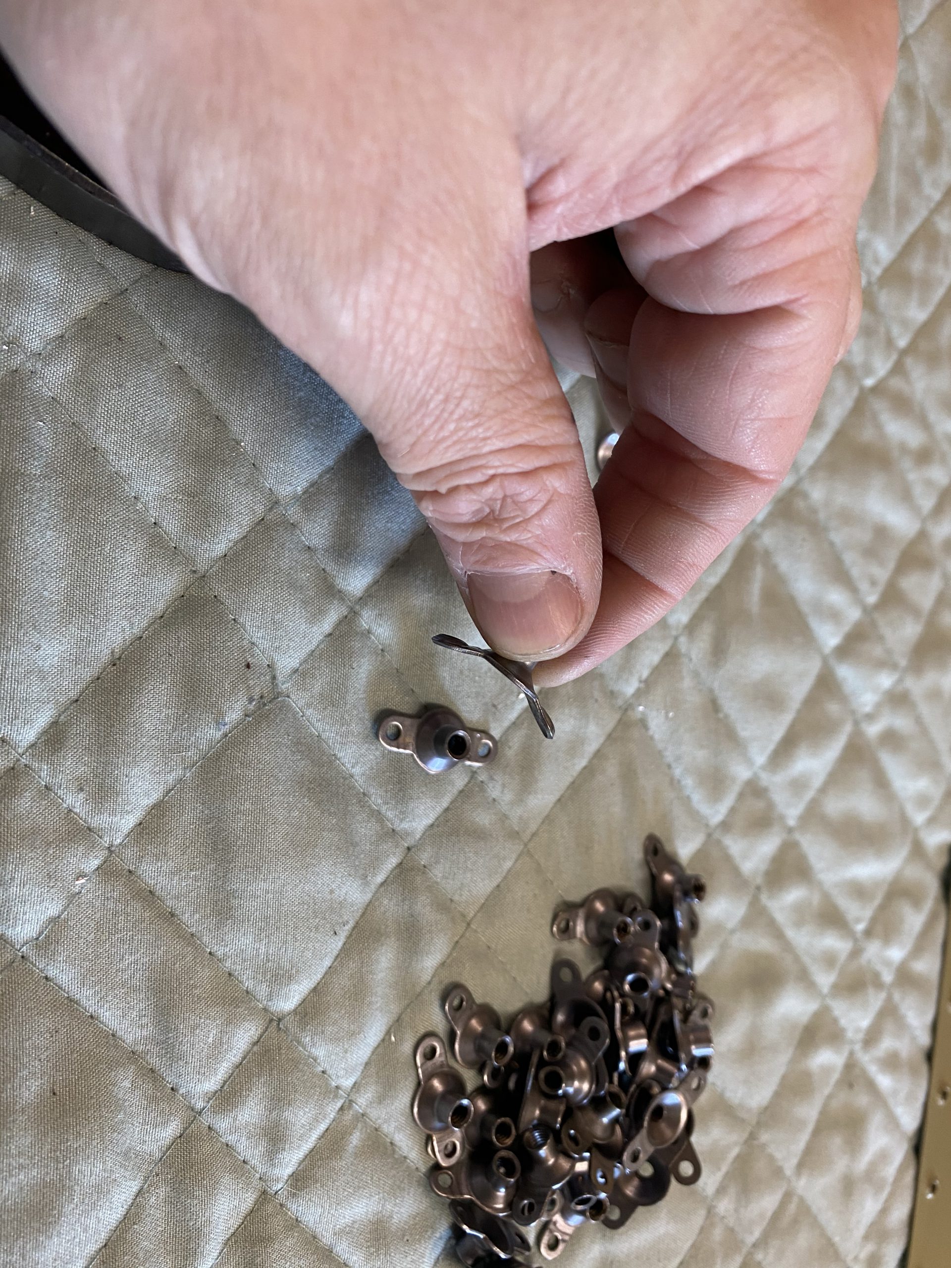
https://www.galassisementi.com/r1nmdgschee I started out by looking up the parts I’d need. There is some oddness on the nutplates. The plans call for us to use K1100-08 nutplates, but we have to dimple the skin so the access plate will sit flush. So, a K1100-09D nutplate makes the most sense, as its already dimpled for the screw AND the rivets. Oddly enough, I have some K1100-08D nutplates in my parts bin, but no where near enough to complete all the access plates. I DO have plenty of K1100-08 nutplates, so I guess Vans’ does indeed intend on us using those silly non-dimpled nutplates, and then dimpling them on our own. I even tested the -08D nutplates on my skins and they work beautifully, with no extra work. Oh well, I’ll use what I have, and do it the way Vans tells me. So, I pulled 48 nutplates from my parts bin, and setup my pneumatic squeezer to dimple the rivet holes in the nutplates. What sucks is the ears get a little bent in the process of dimpling them.
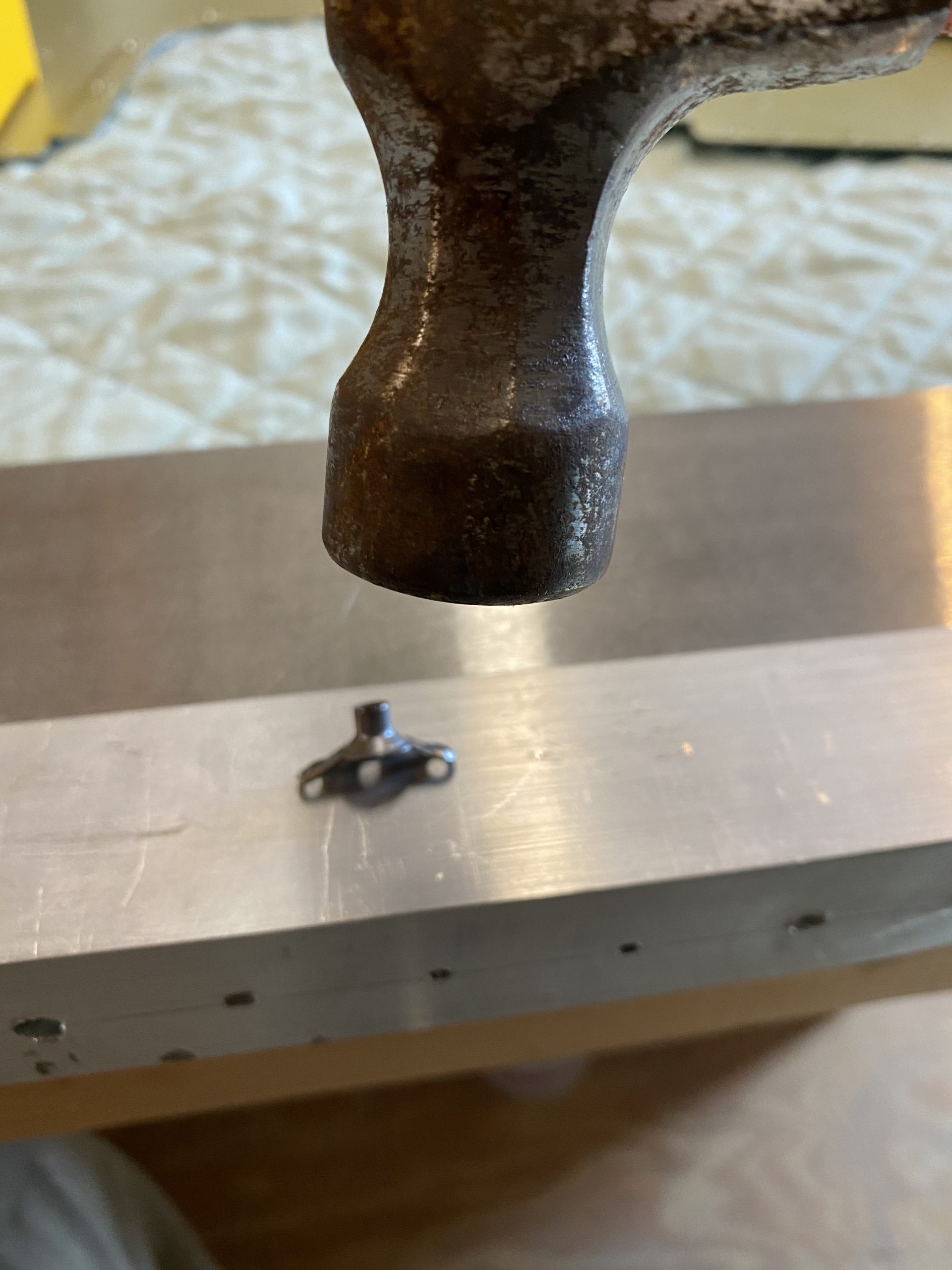
follow link So, I have to straighten them back out. I’ve done this in the past with my back riveting plate and a piece of sacrificial aluminum on top of the plate to avoid scratching my fancy back rivet plate. So, after I had all 48 of the nutplates dimpled, I gave them a gently tappy-tap with a hammer on my aluminum / backplate combo to get them nice and straight. Repeat this 48 times, and all 48 of the K1100-08 nutplates are converted into K1100-08D 🙂
https://debraguthriemd.com/glaucoma/ 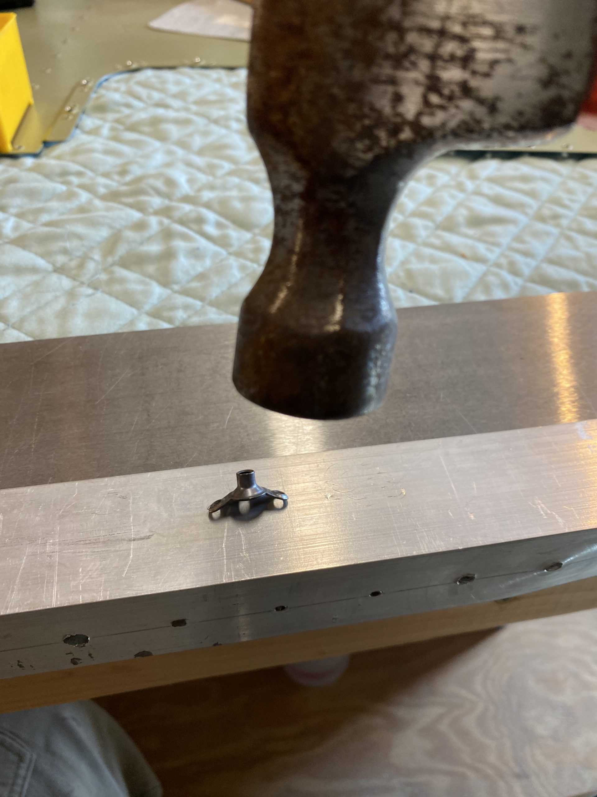
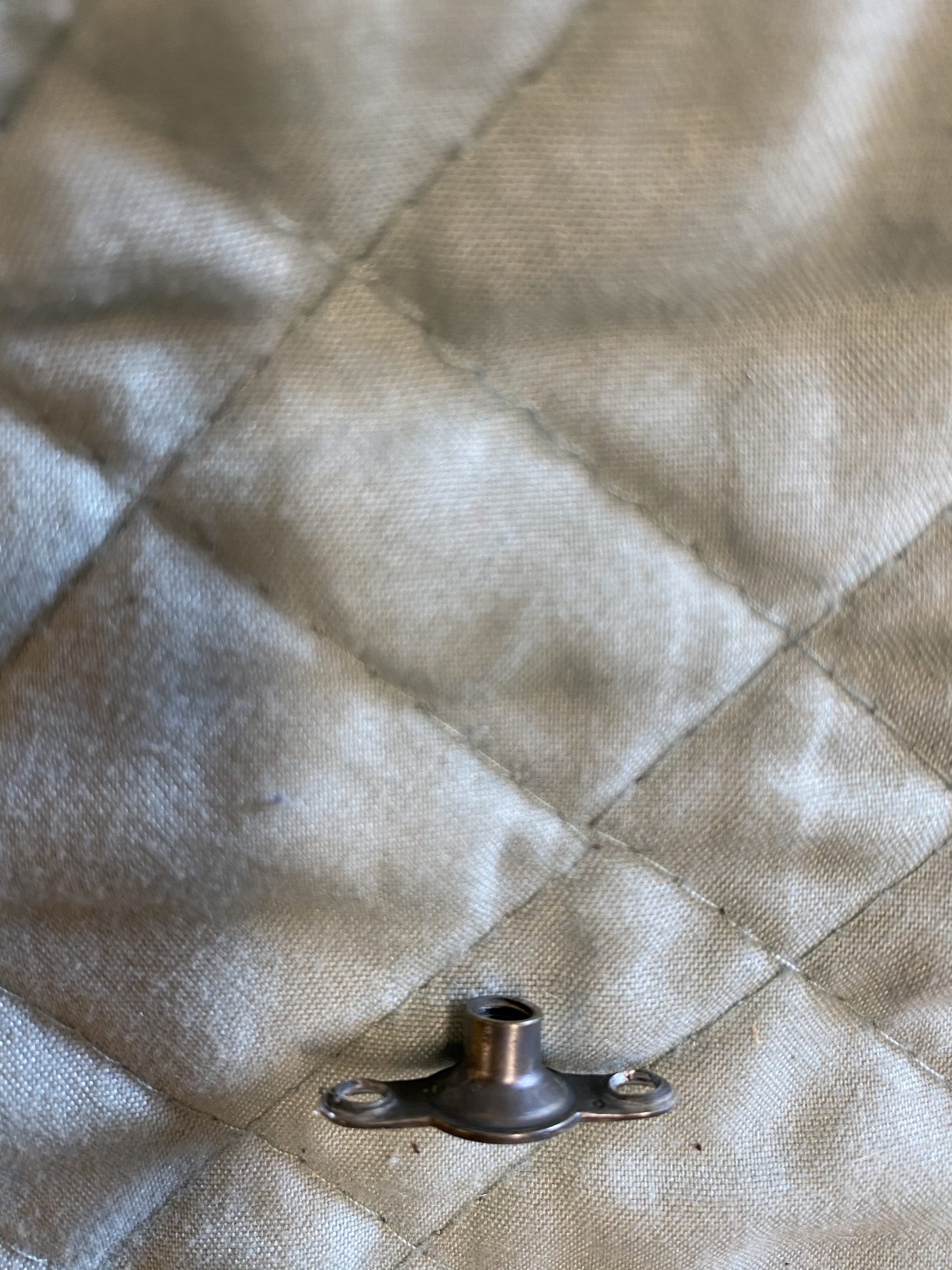
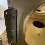
https://serenitycareandcompassion.com/y0vyrvubrf And they fit onto the skin nice and smooth and flush, ready to be riveted on.
https://marchtozion.com/vtfrvji 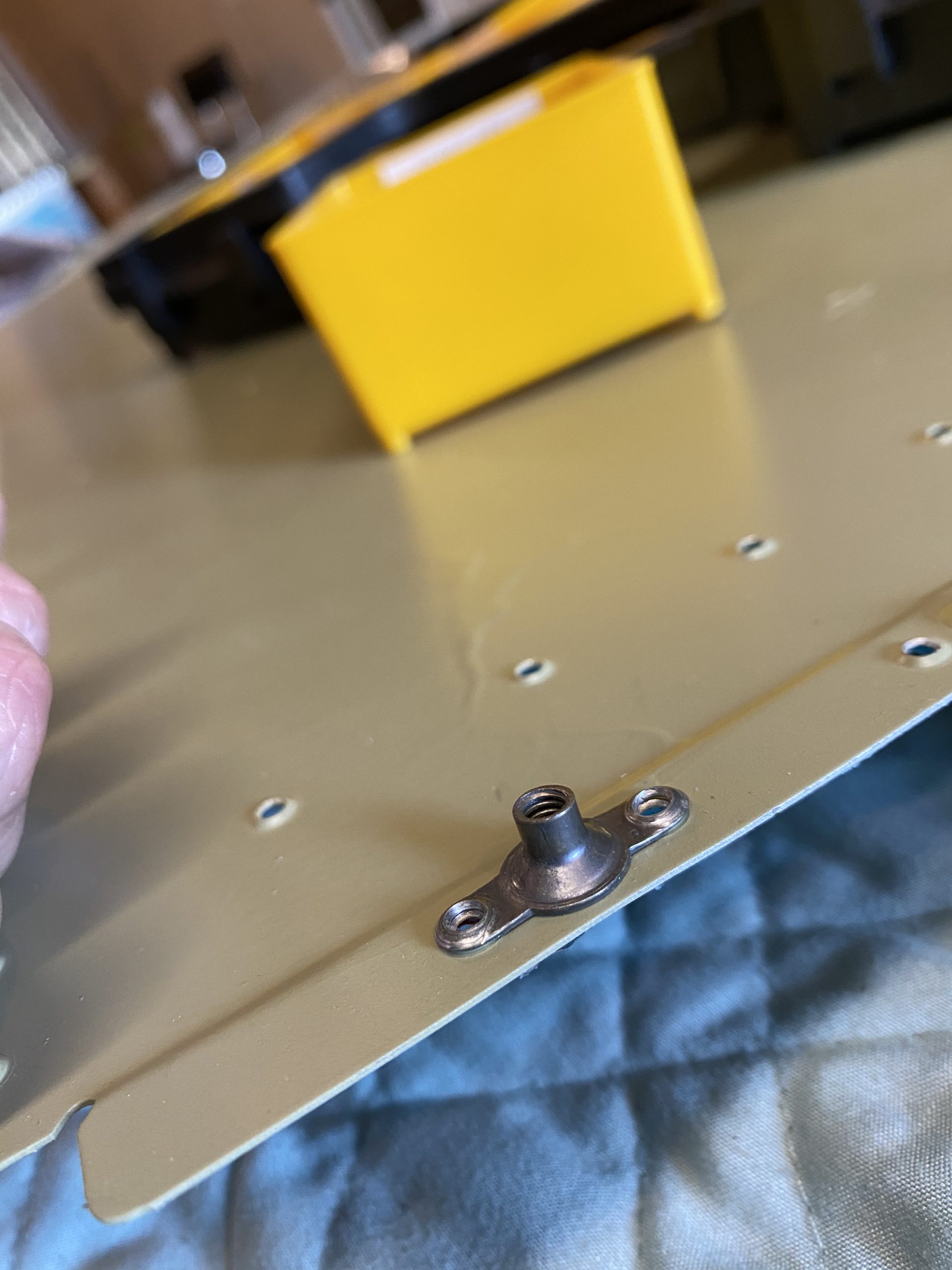
go to link Now that I have my nutplates ready, I needed to remove the blue plastic from the access plate area so I can rivet everything. I used the soldering iron trick to do this quickly.
https://www.doktressmelange.com/2025/06/17/txloigfti2 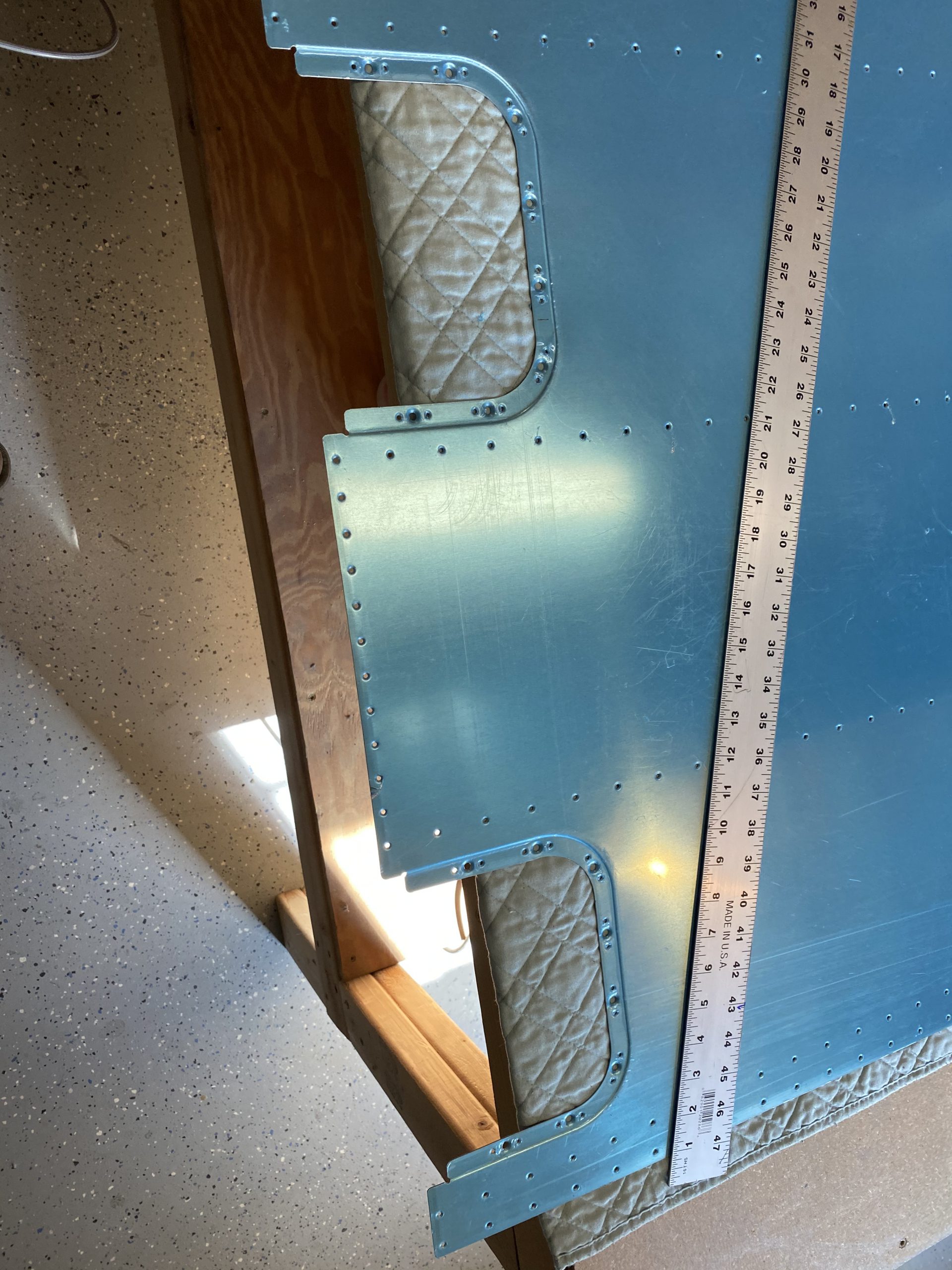
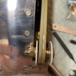
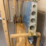
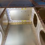
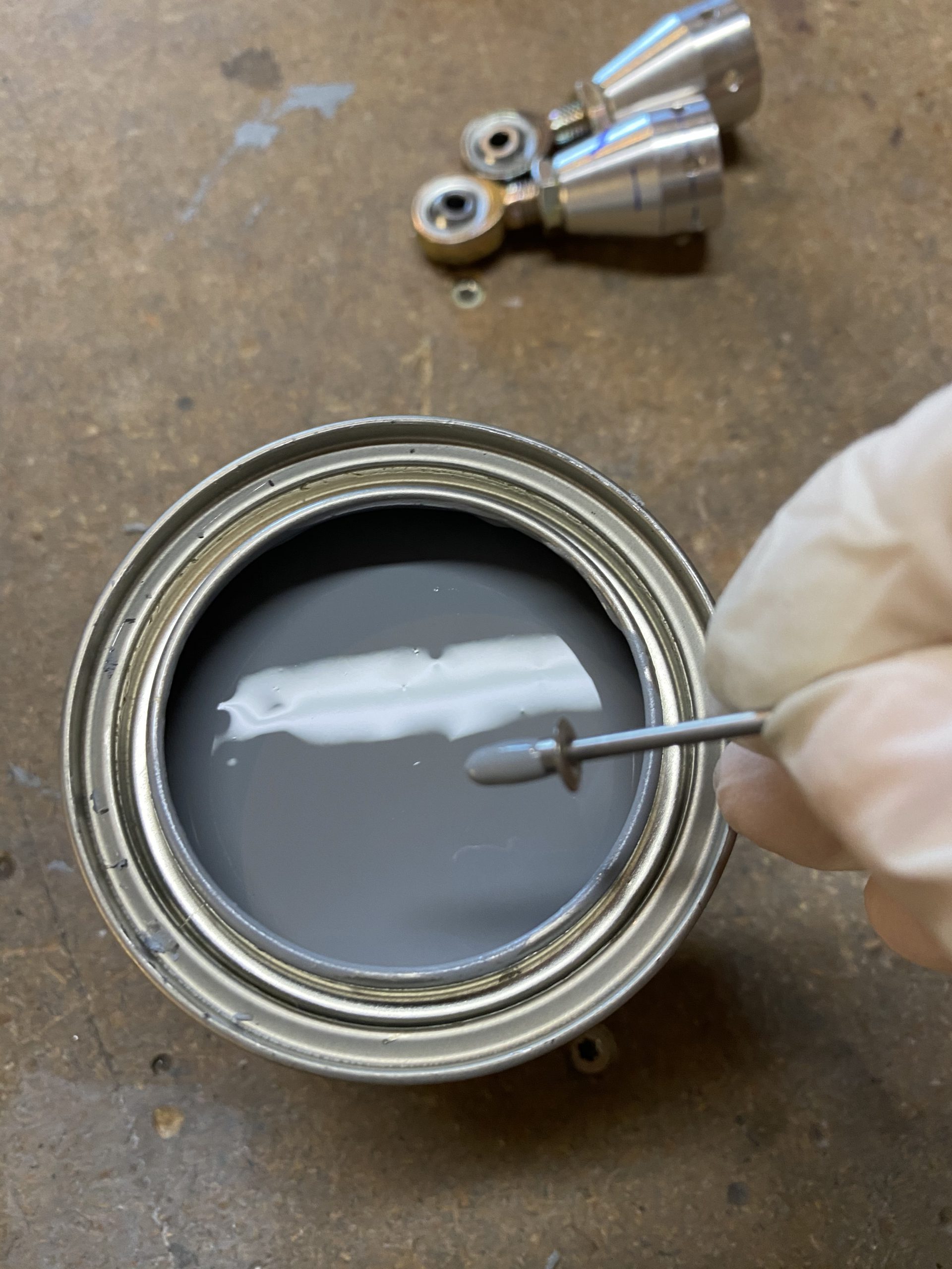
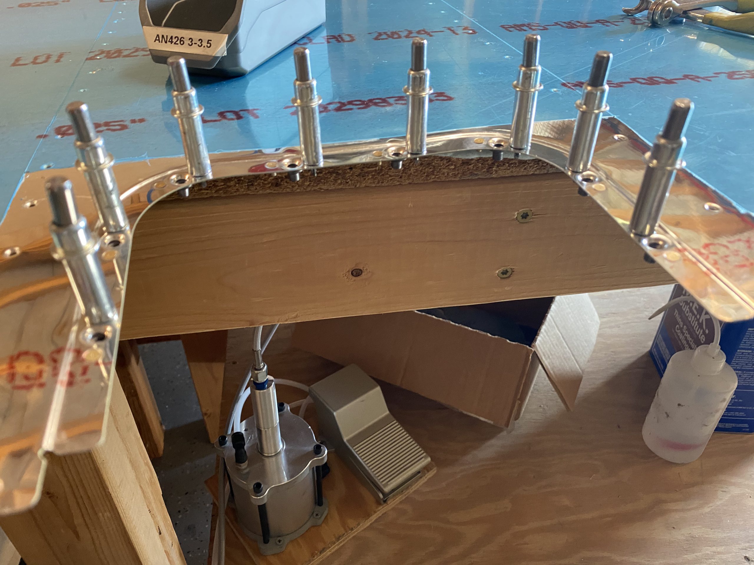
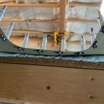
https://retailpanama.com/35dsqidouu3 Now, we’re ready to cleco on the nutplates and squeeze the rivets into place. The plans calls for AN426AD3-3.5, and they worked our very nicely.
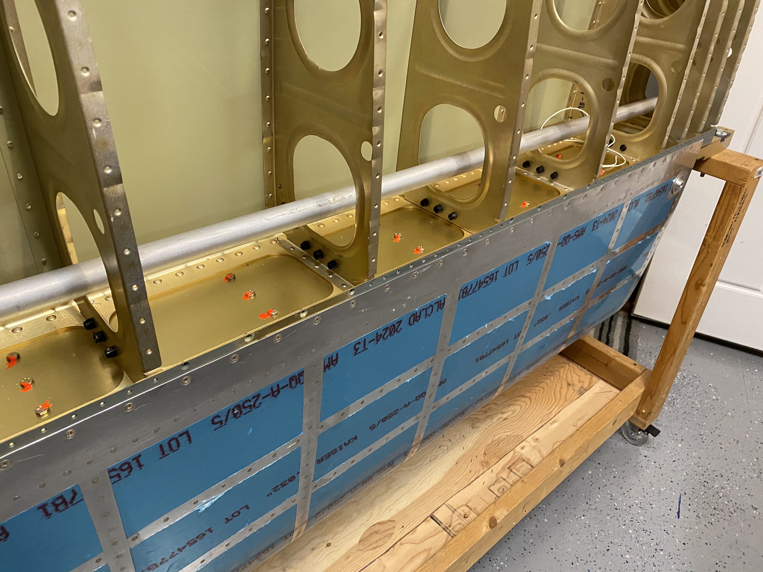
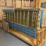
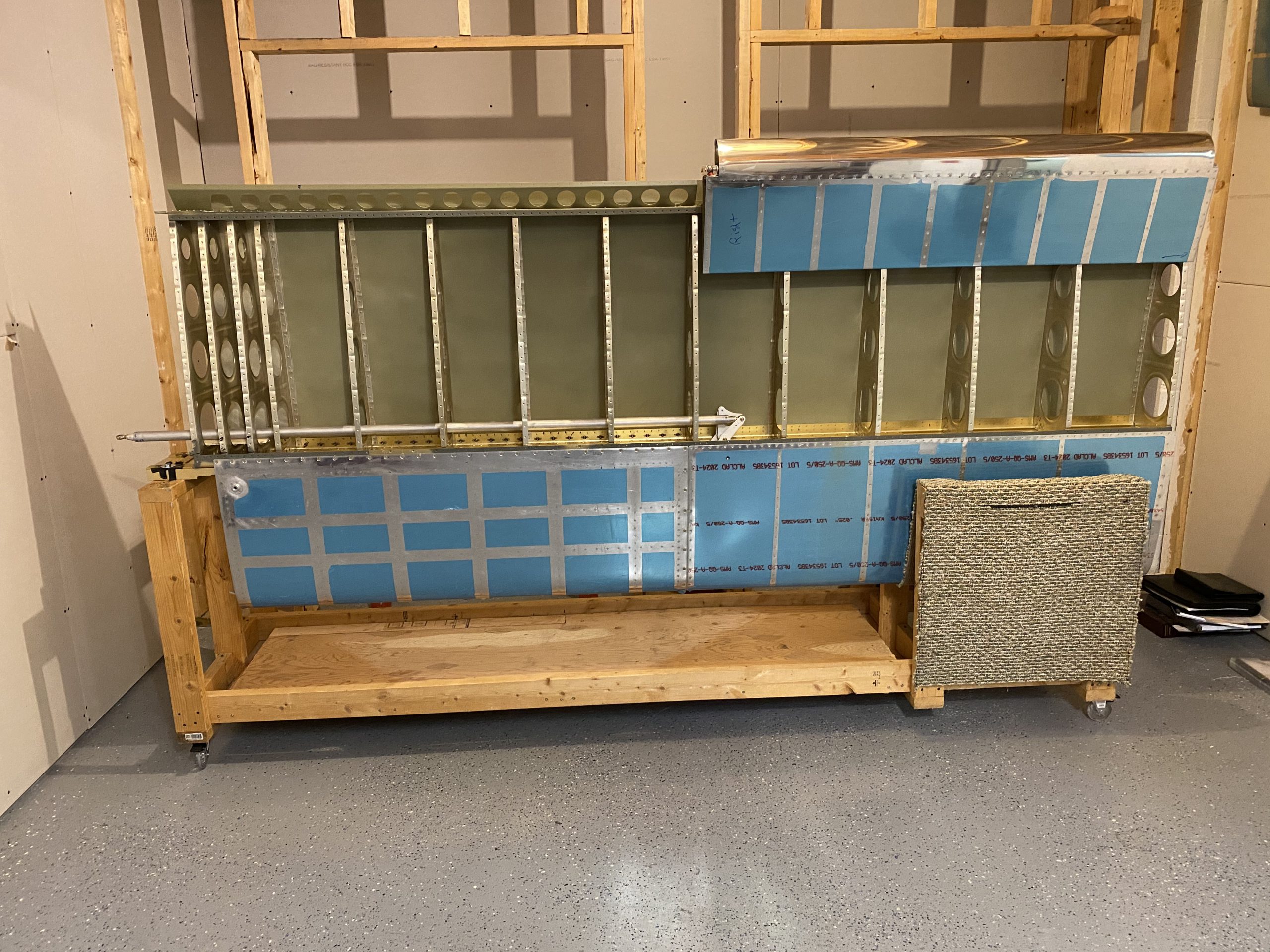
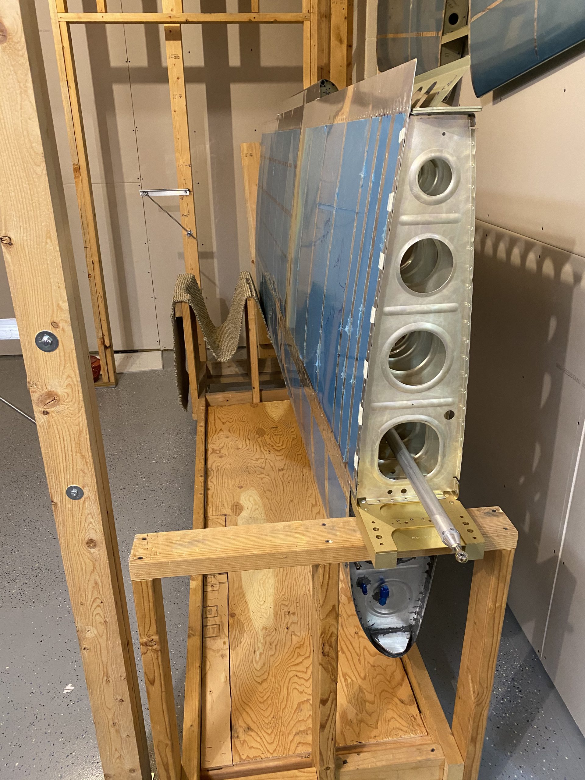
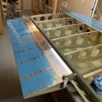
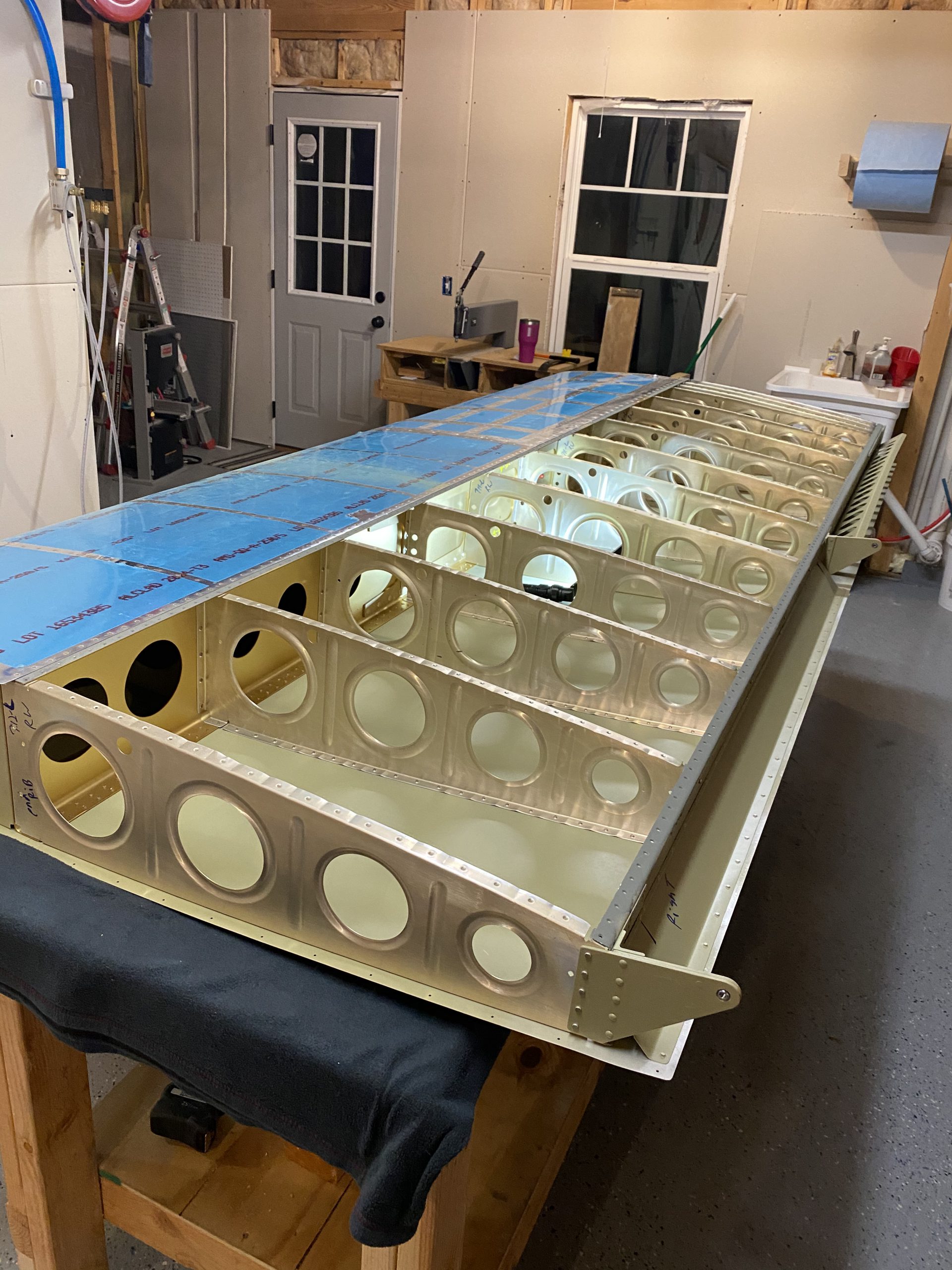
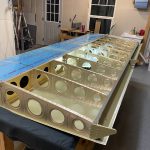
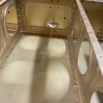
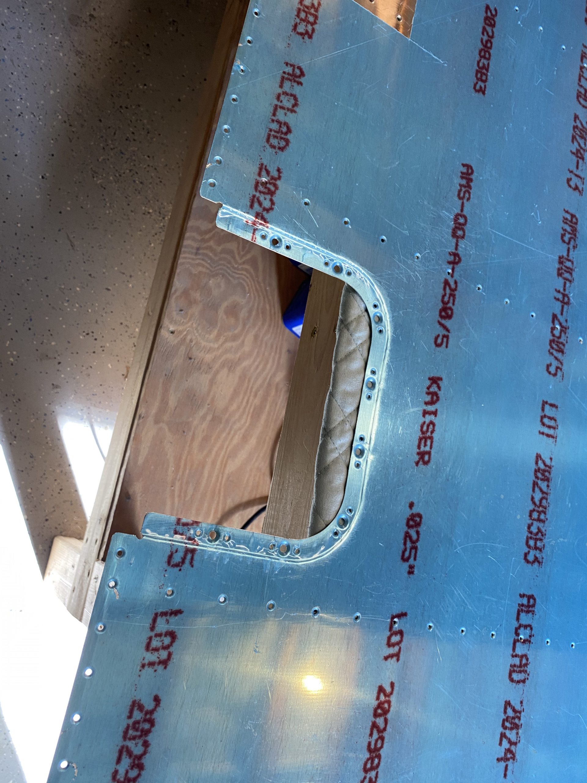
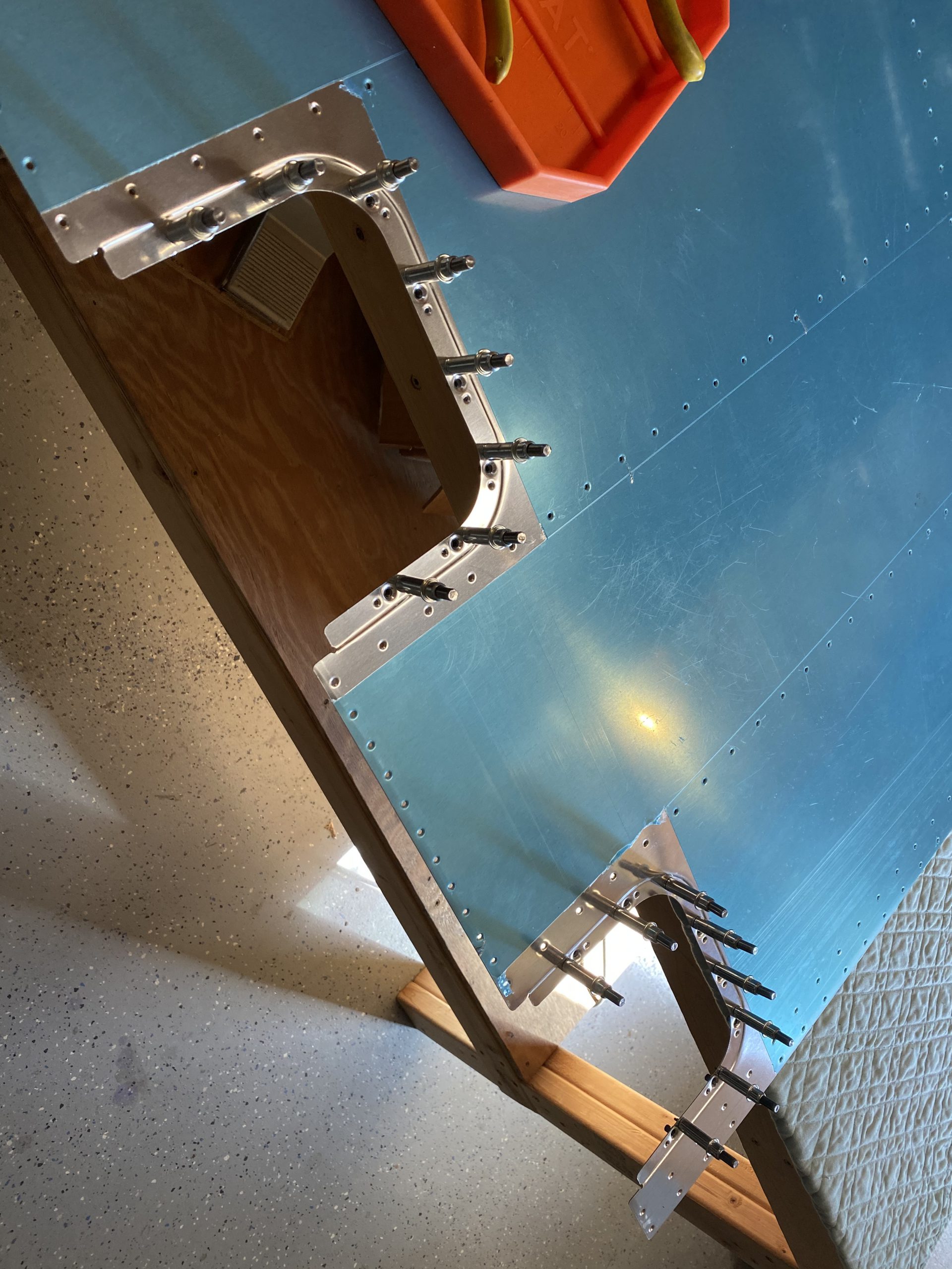
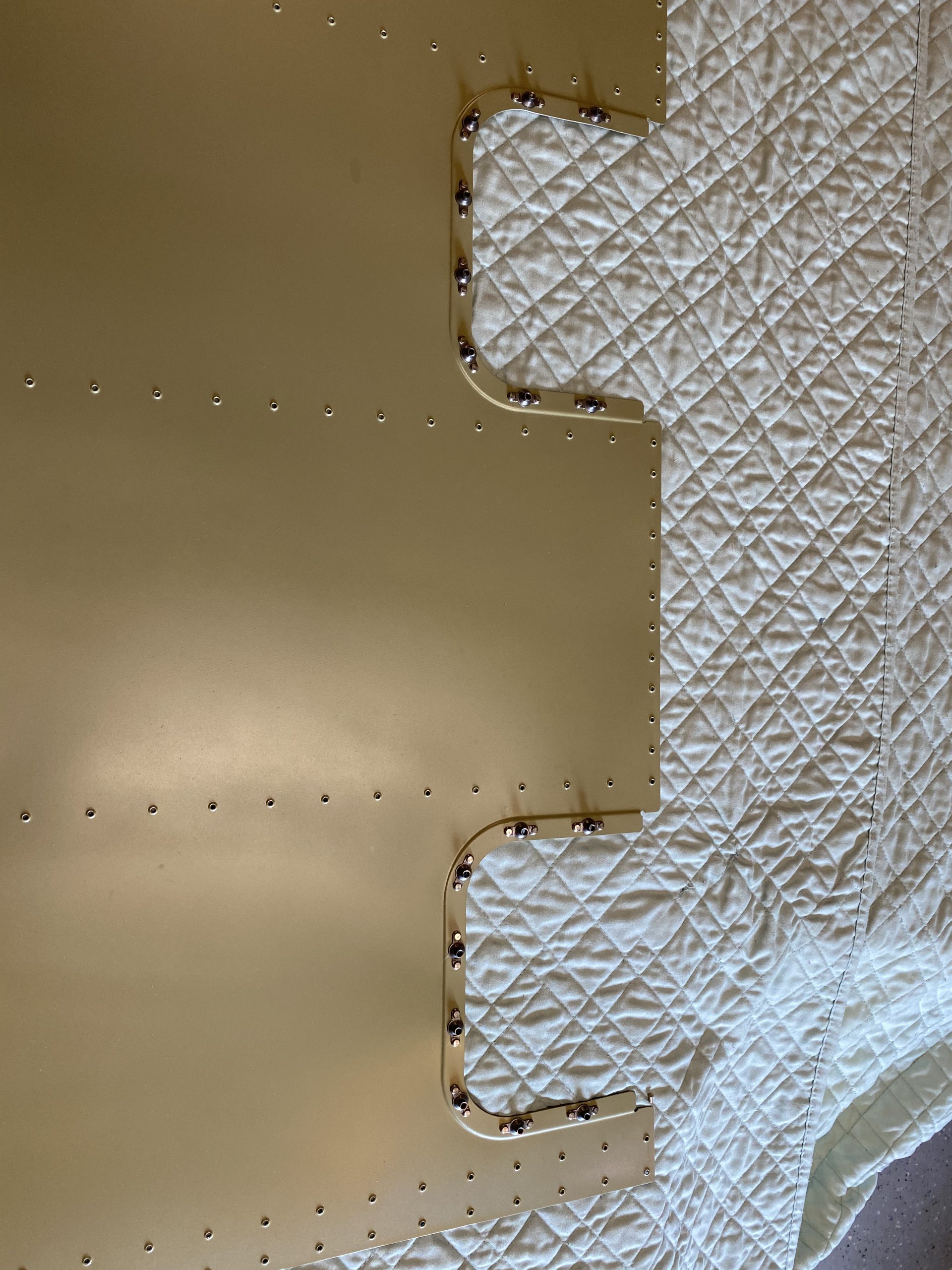
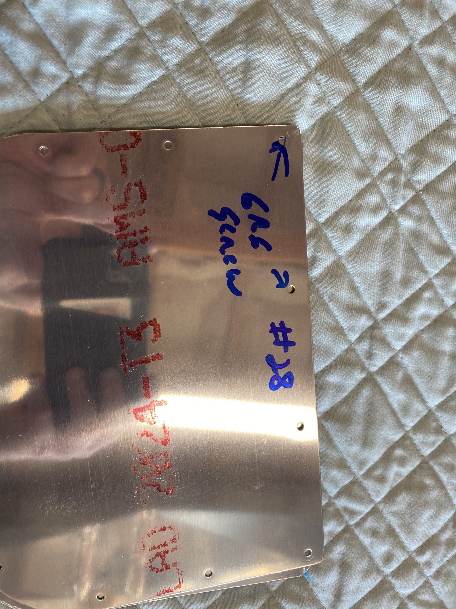
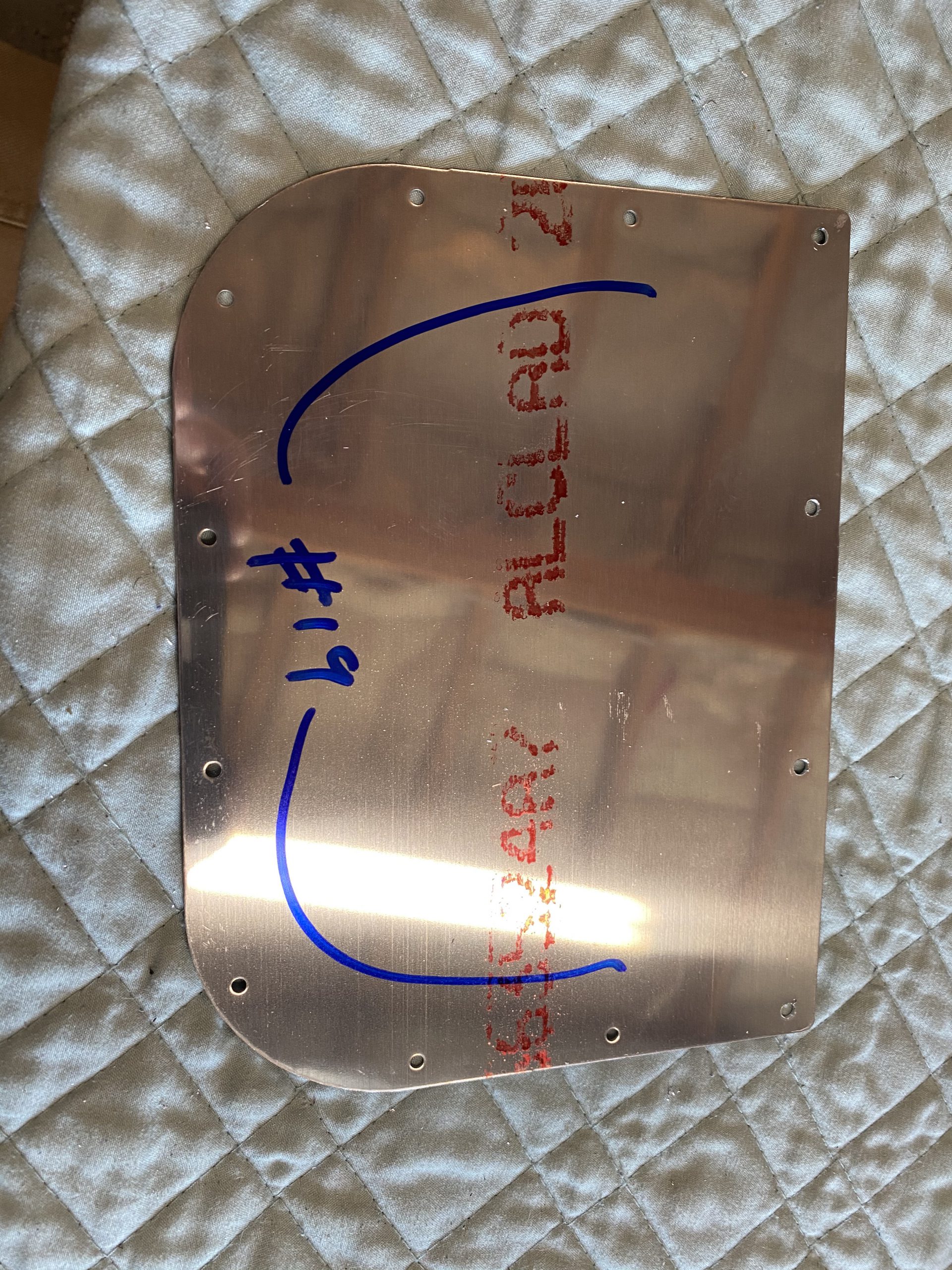
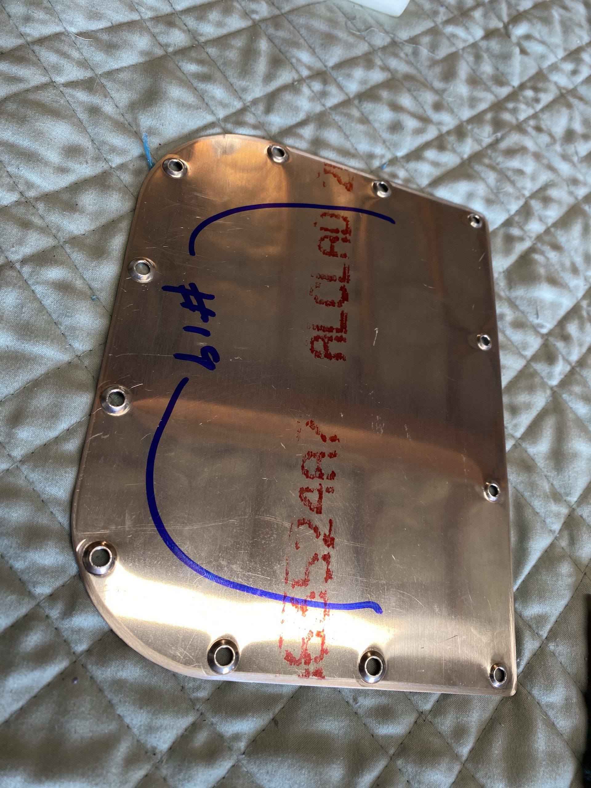
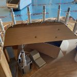
https://www.starc.org/uncategorized/8wjl6ezglp I repeated this process of clecoing and riveting on all 4 of the bottom skins. Eventually, I had all of the nutplates riveted on to every one of the bottom skins, and they look really nice. Now its time to move on to the actual W-822 access plates. I grabbed all 6 from their storage shelf, and removed all of the blue plastic.
https://genevaways.com/o1f9i1fee6 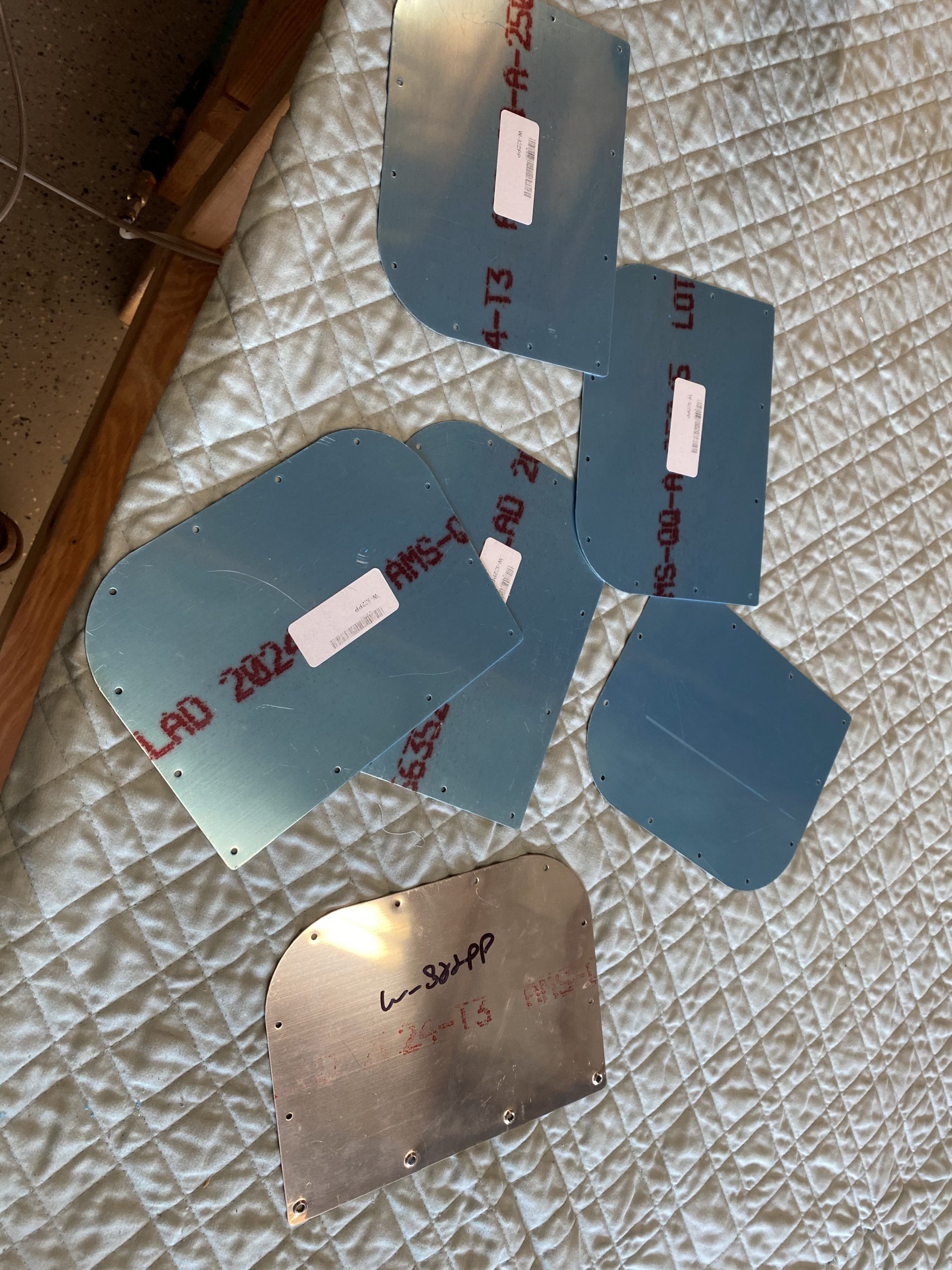
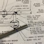
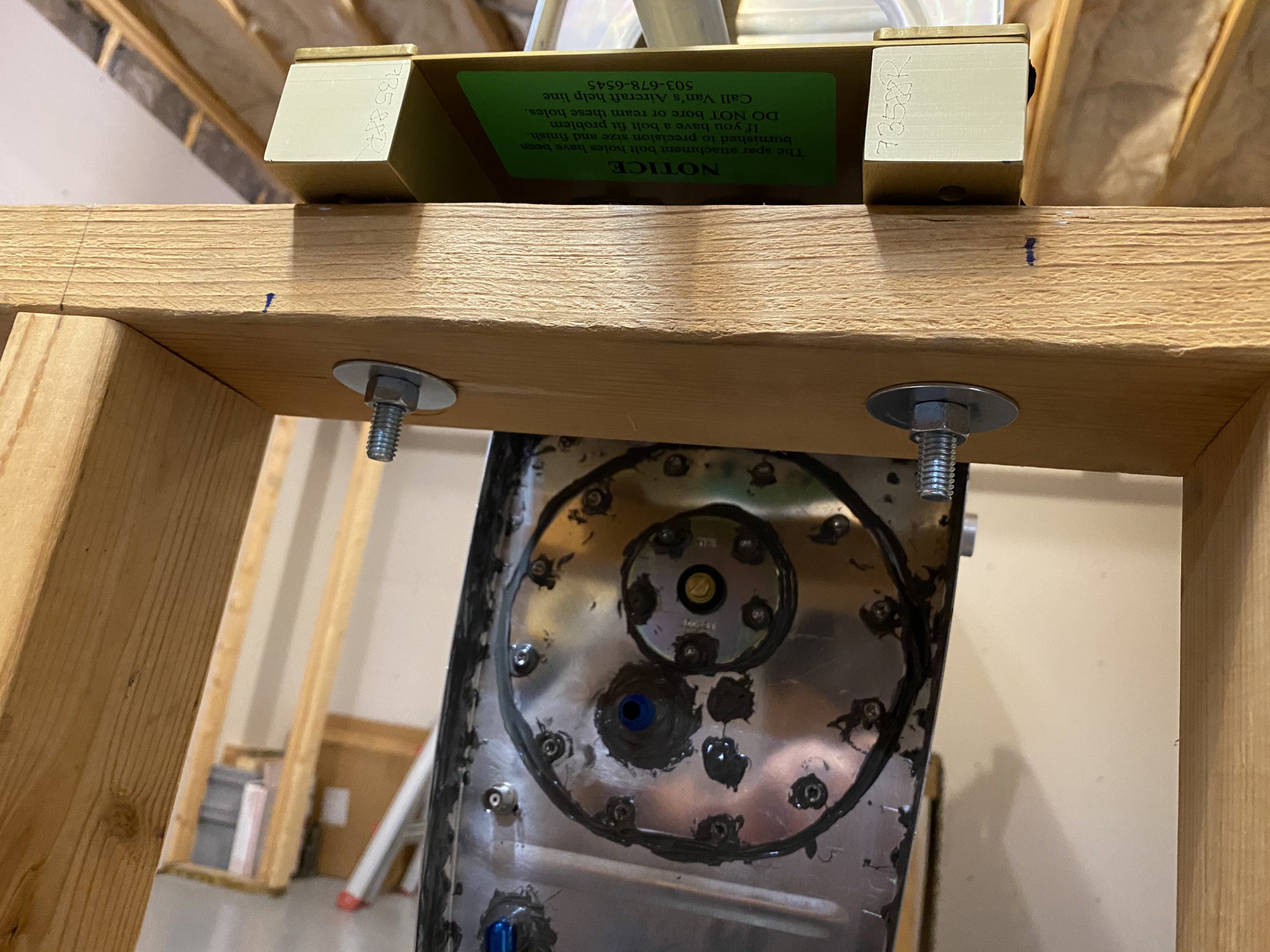
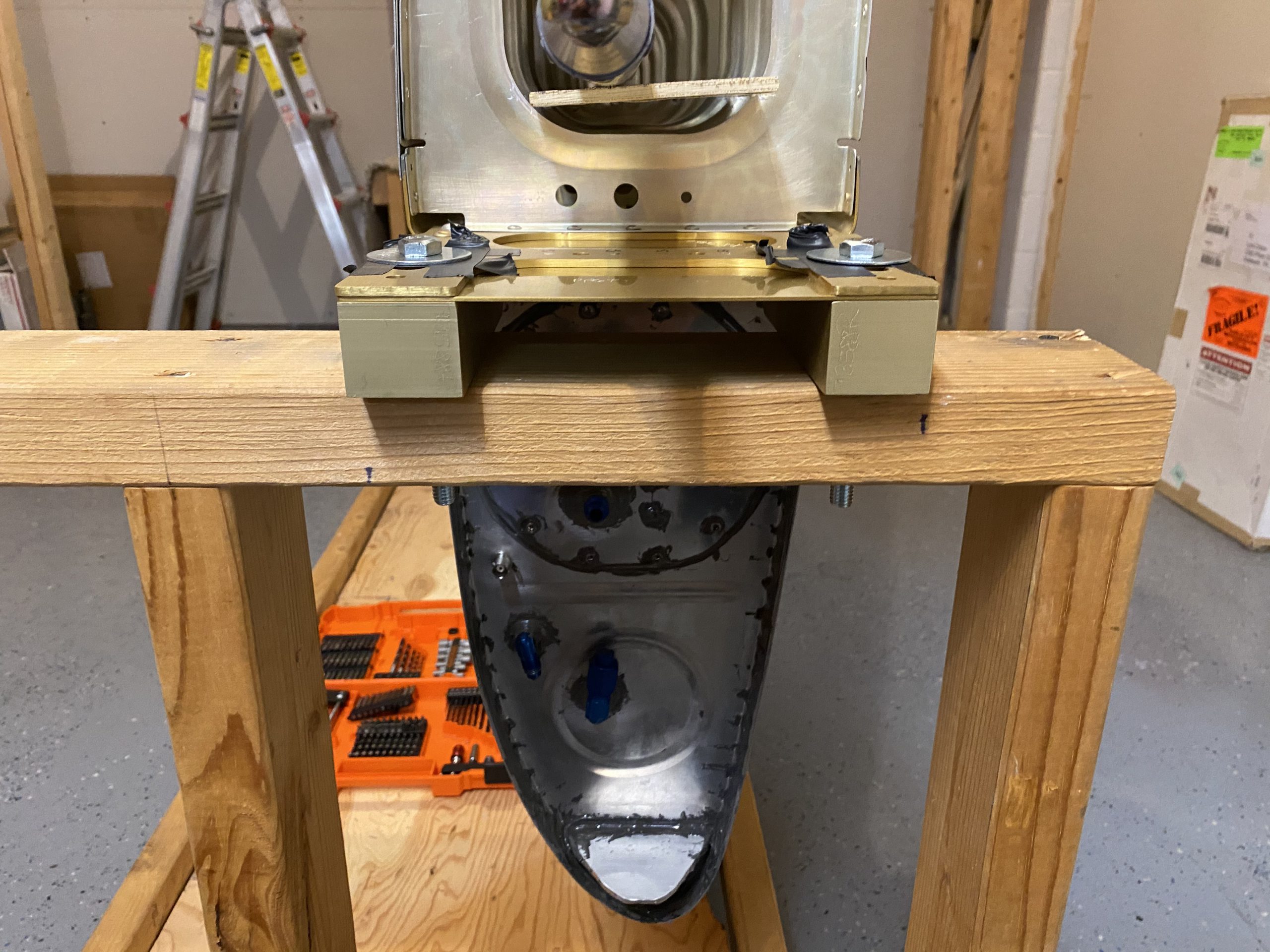
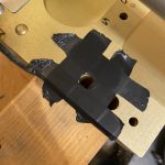
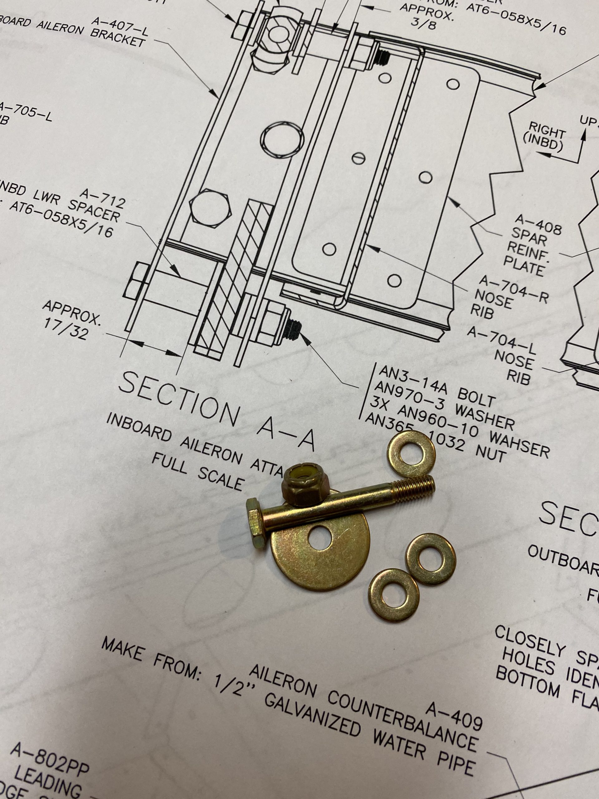
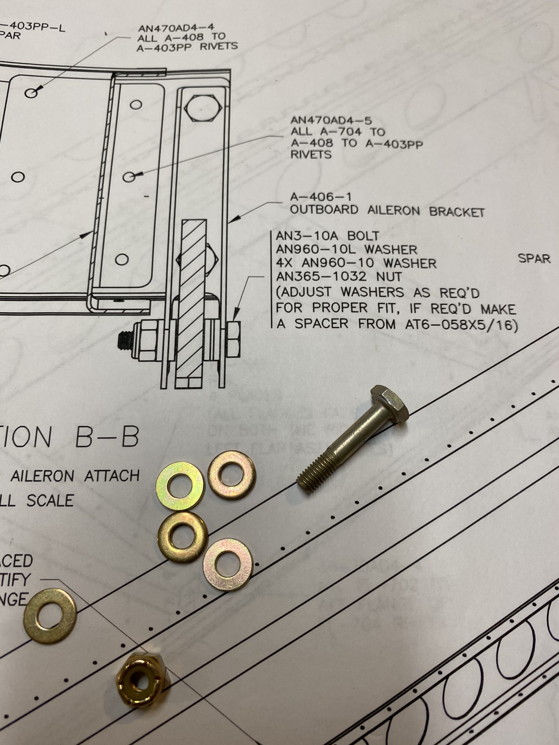
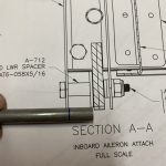
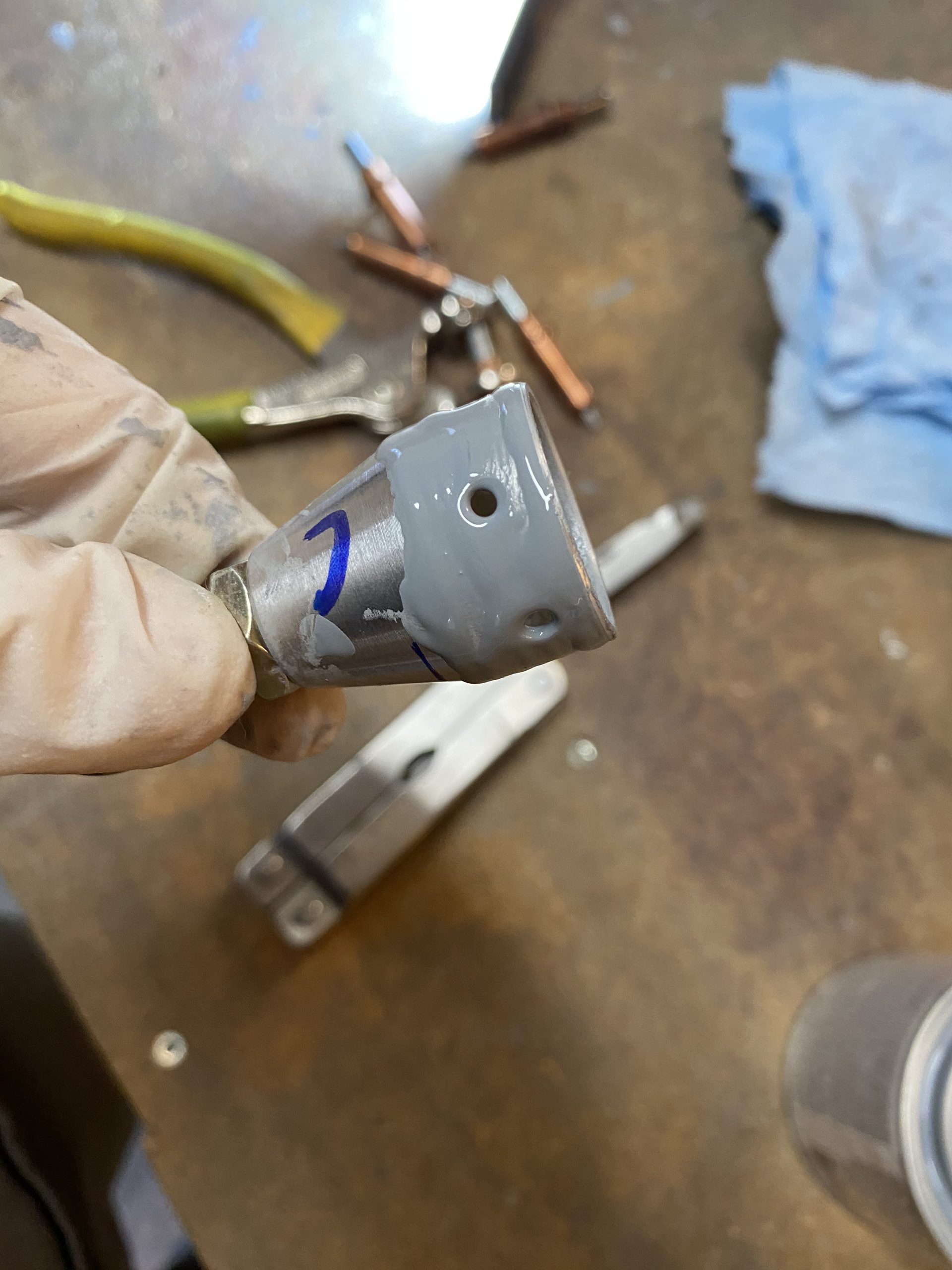
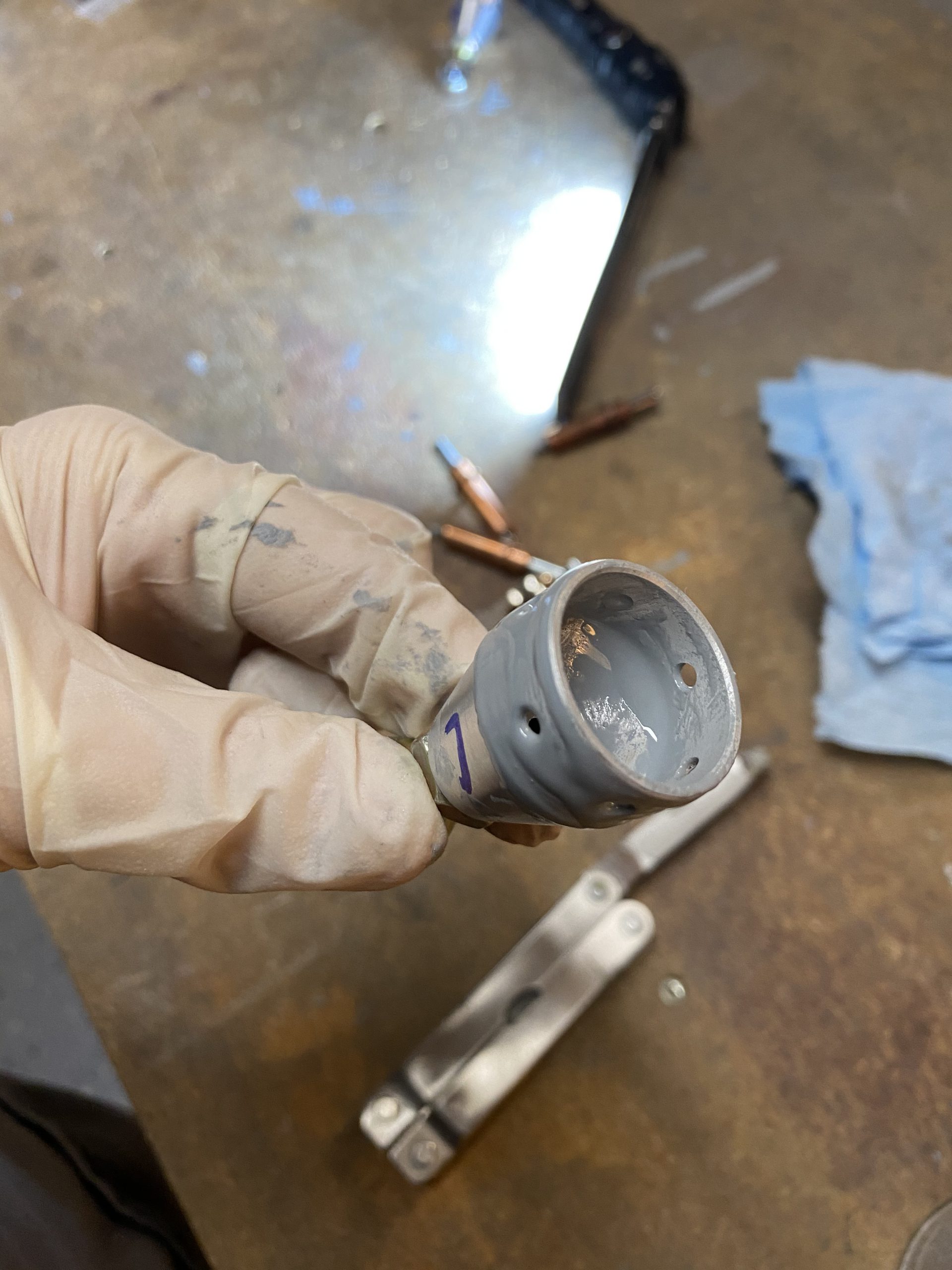
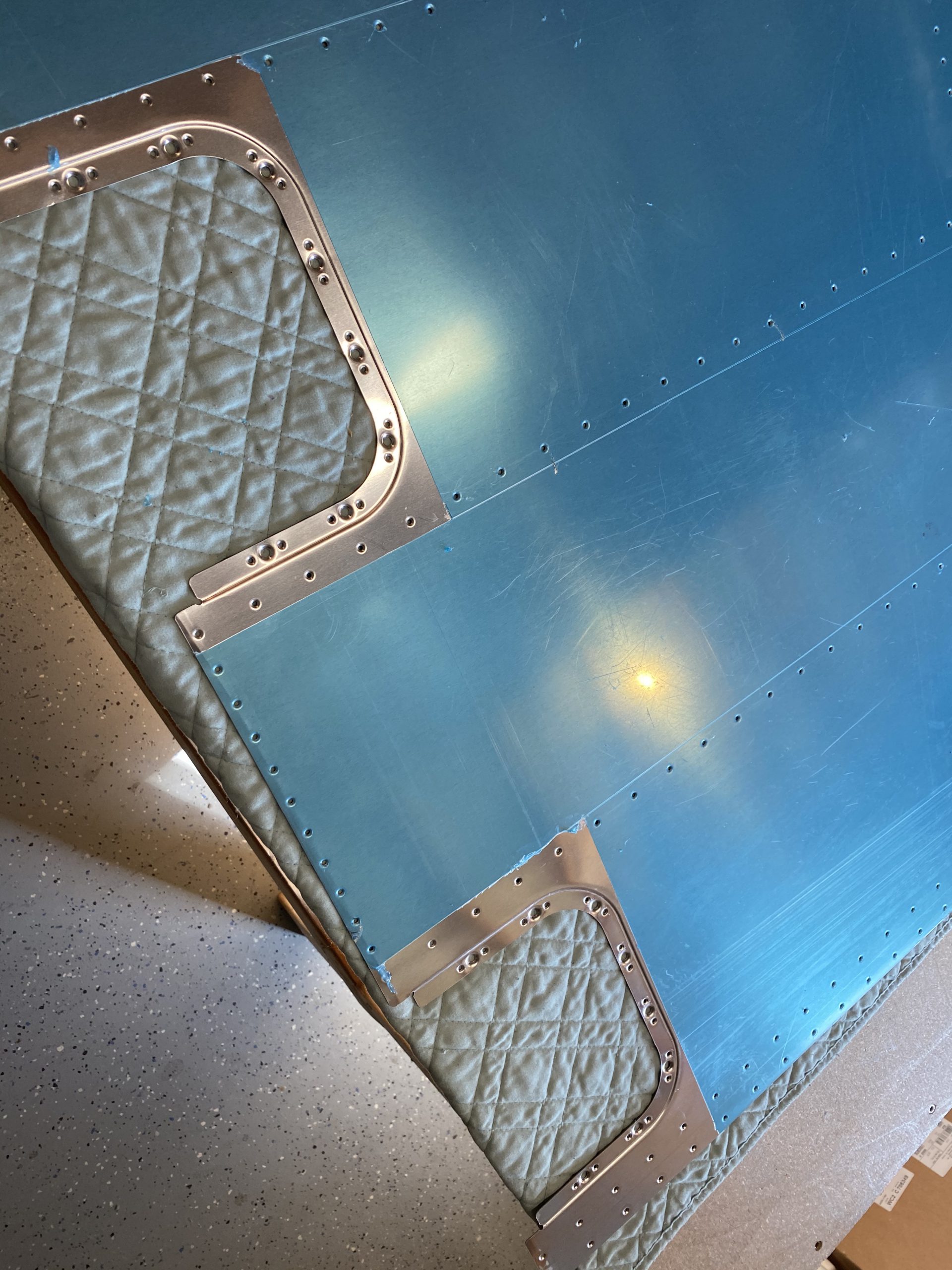
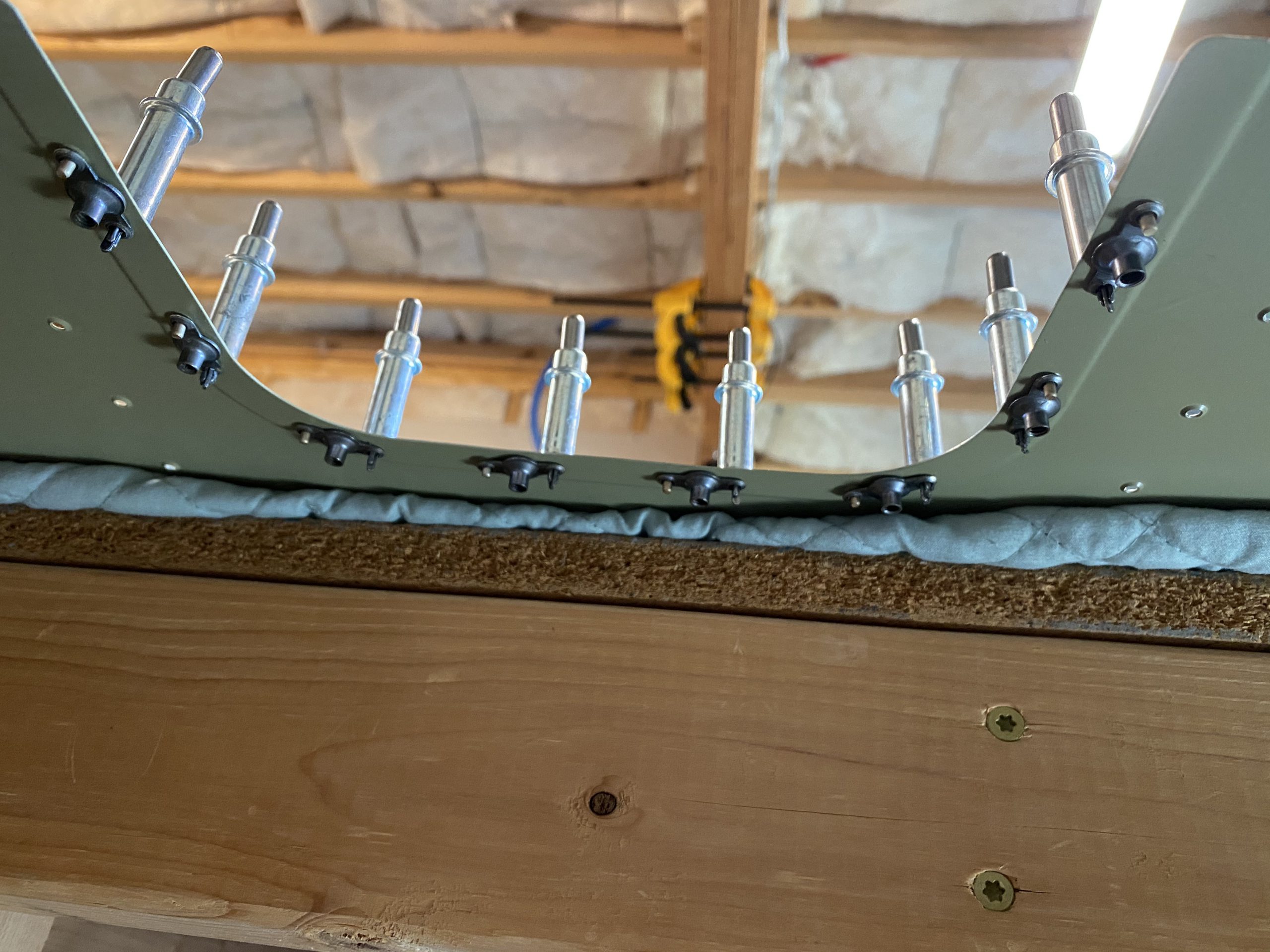
https://wonderpartybcn.com/fyqknfqep Looking at the plans, the portion of the access plate (towards the leading edge) that gets screwed to main spar flange uses a smaller screw, sized at AN507-6R6, the remaining holes that screw into the lip on the skins use the larger AN609-8R8 screw. This means they will need a different size hole drilled, and a different dimple. The 6R6 holes need a #28 drill bit, and the larger 8R8 need a #19 I marked the holes as an example.
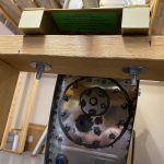
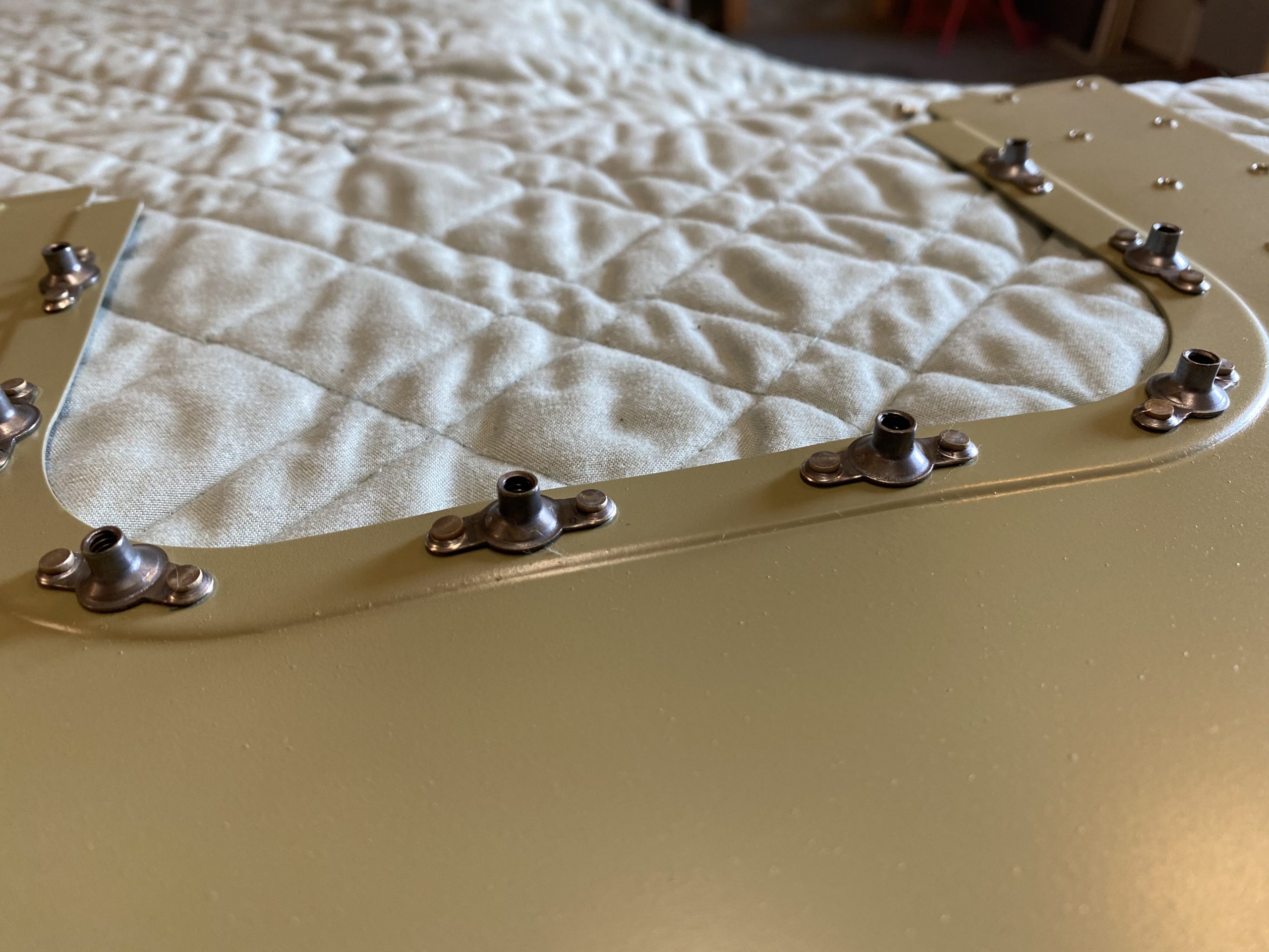
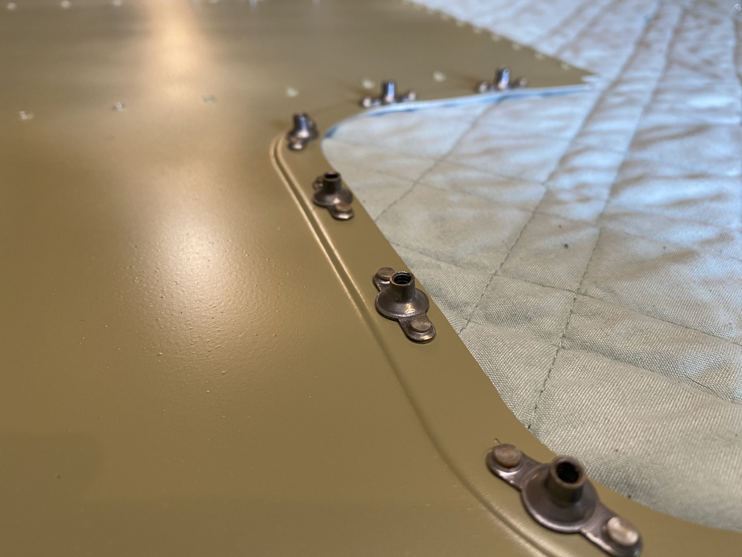
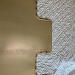
https://marchtozion.com/7bxx5epr Then I drilled all the pre-punched holes up to the size they needed to be. Then I deburred all the newly drilled holes on both sides, and deburred the edges of all the plates with a scotchbrite wheel. Next was to dimple the holes. I used the respective dimple dies for the #6 and #8 holes and used the squeezer to make a very nice dimple in the access plate with zero warping.
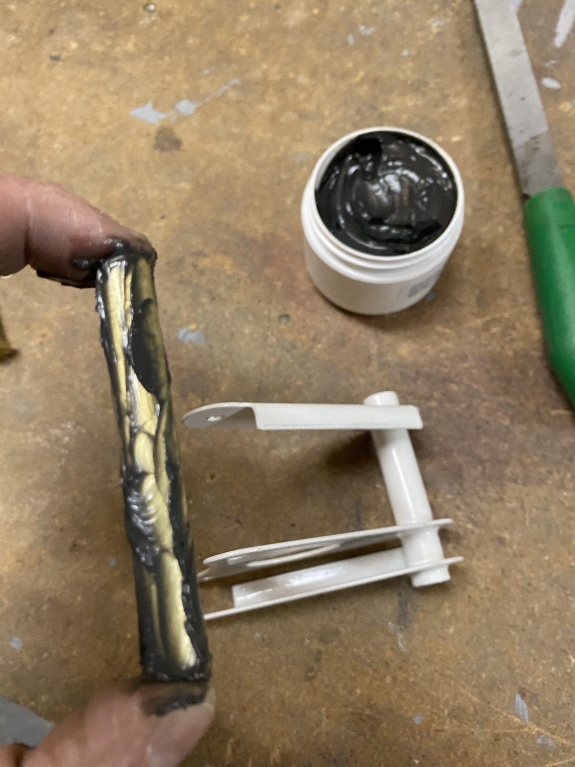
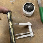
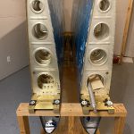
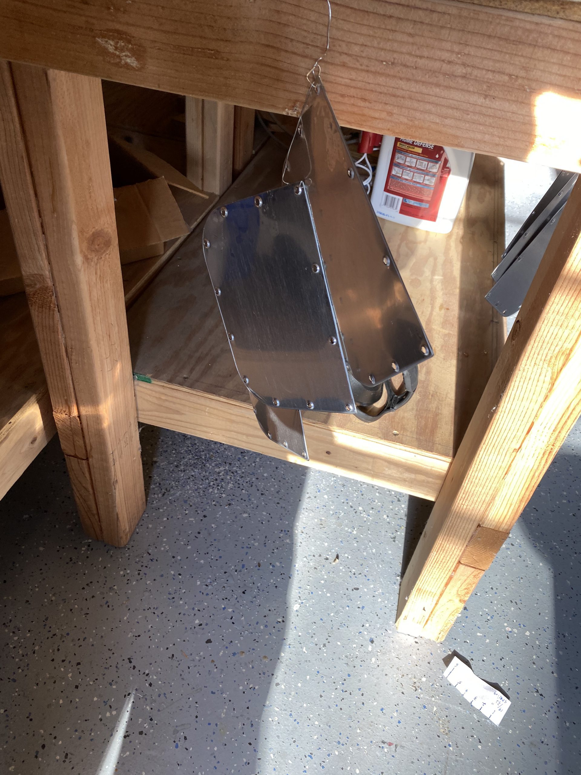
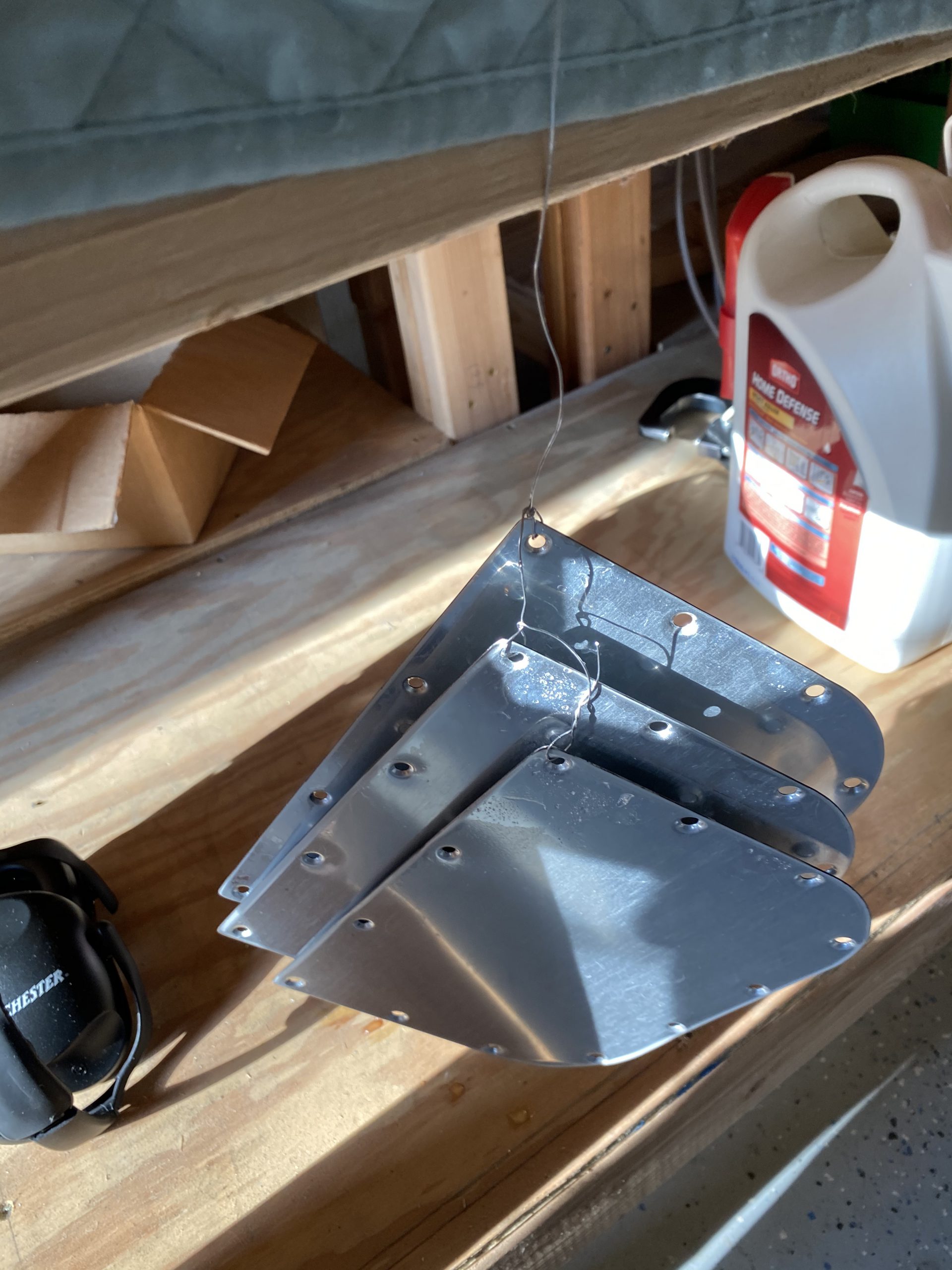
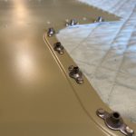
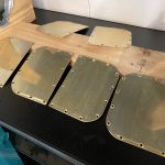
https://www.starc.org/uncategorized/8q8b7wk9 Now these plates are ready for corrosion protection! I cleaned them off with some acetone, then I stringed them onto some safety wire, giving them plenty of spacing, and dipped them into my alumaprep33 bucket so they can etch.
https://soccertrainingsolutions.com/affiliate-disclosure-privacy-policy/ 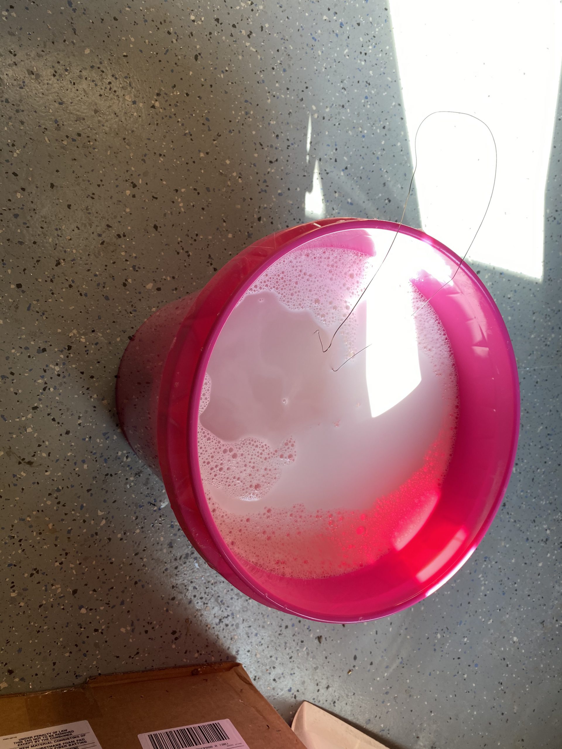
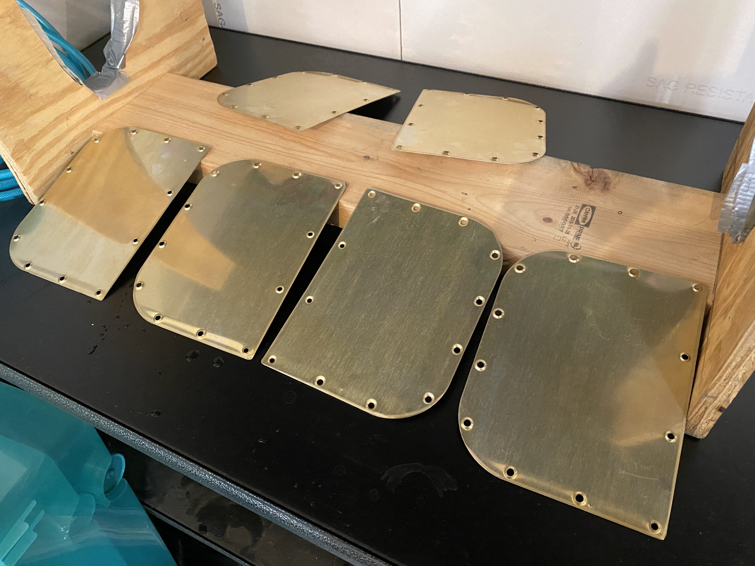
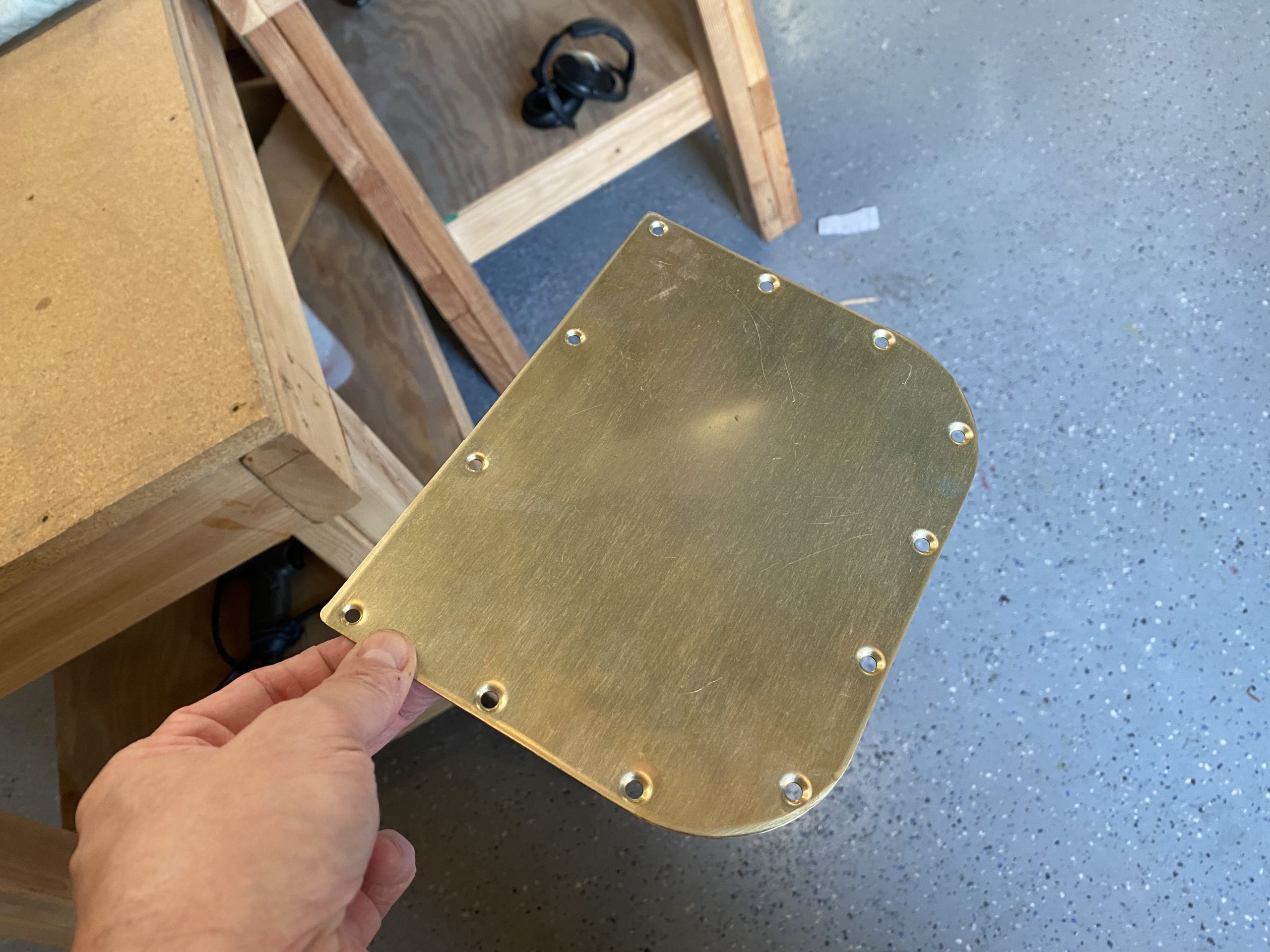
https://estherbarniol.com/rdg47z95j9t After they soaked and got etched, I dipped them into an alodine bath for about 20 minutes. I didn’t snap a pic of the baths, but you can see the results in these photos. They came out a beautiful golden color.
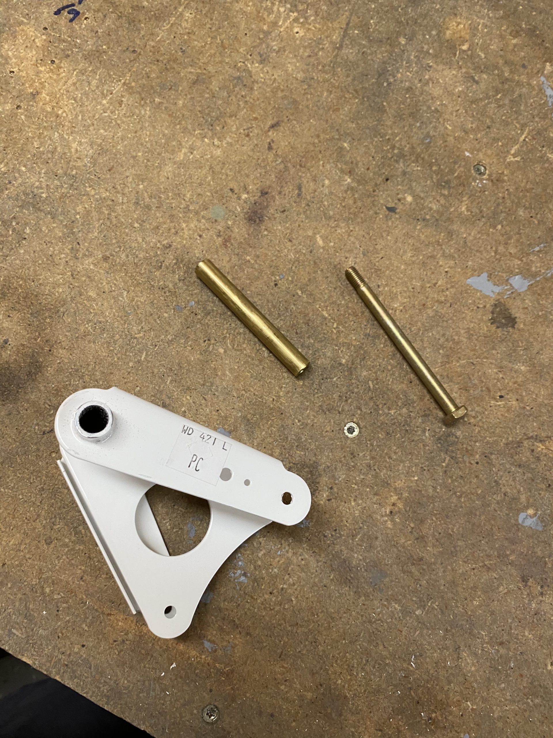
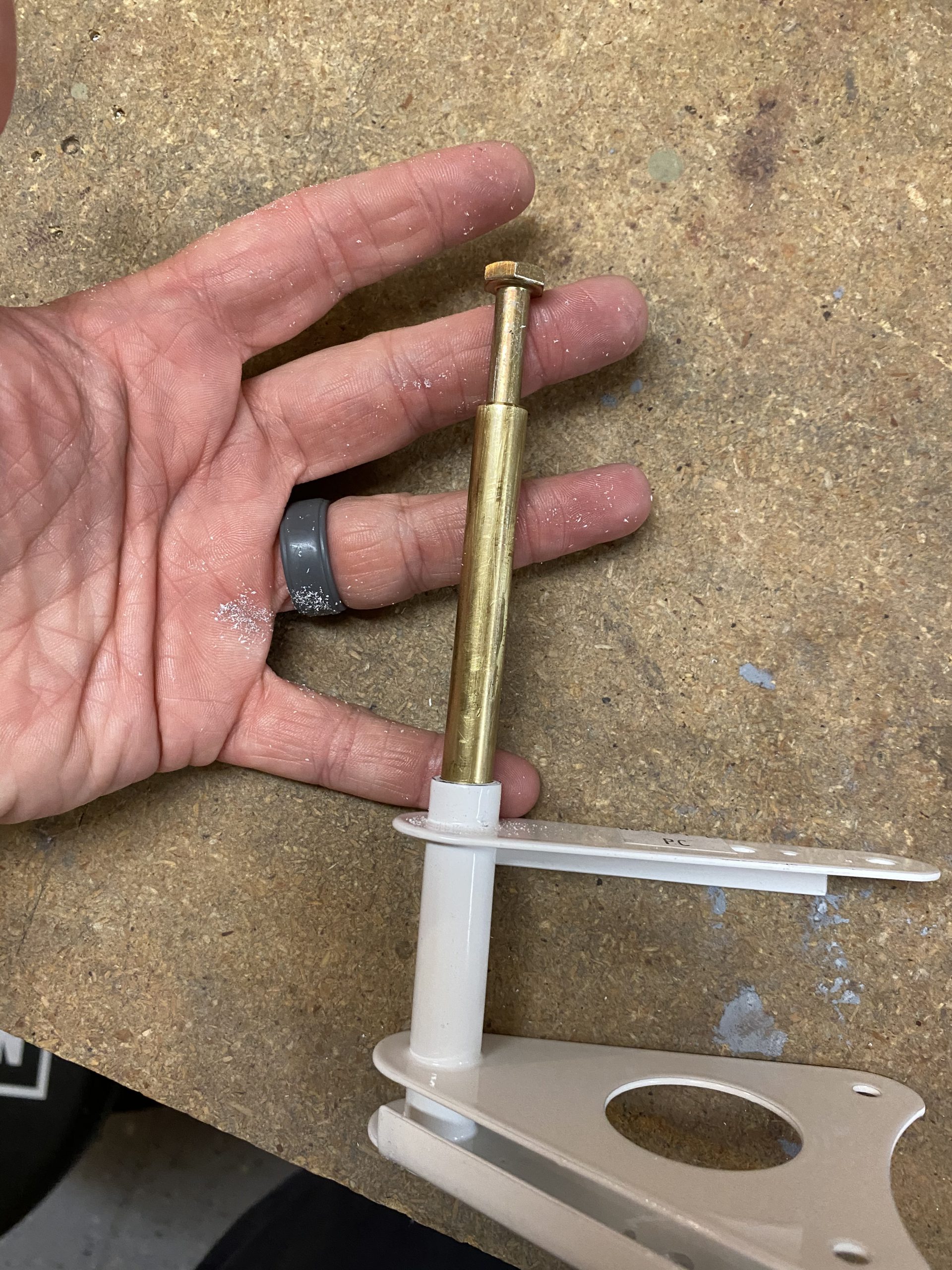
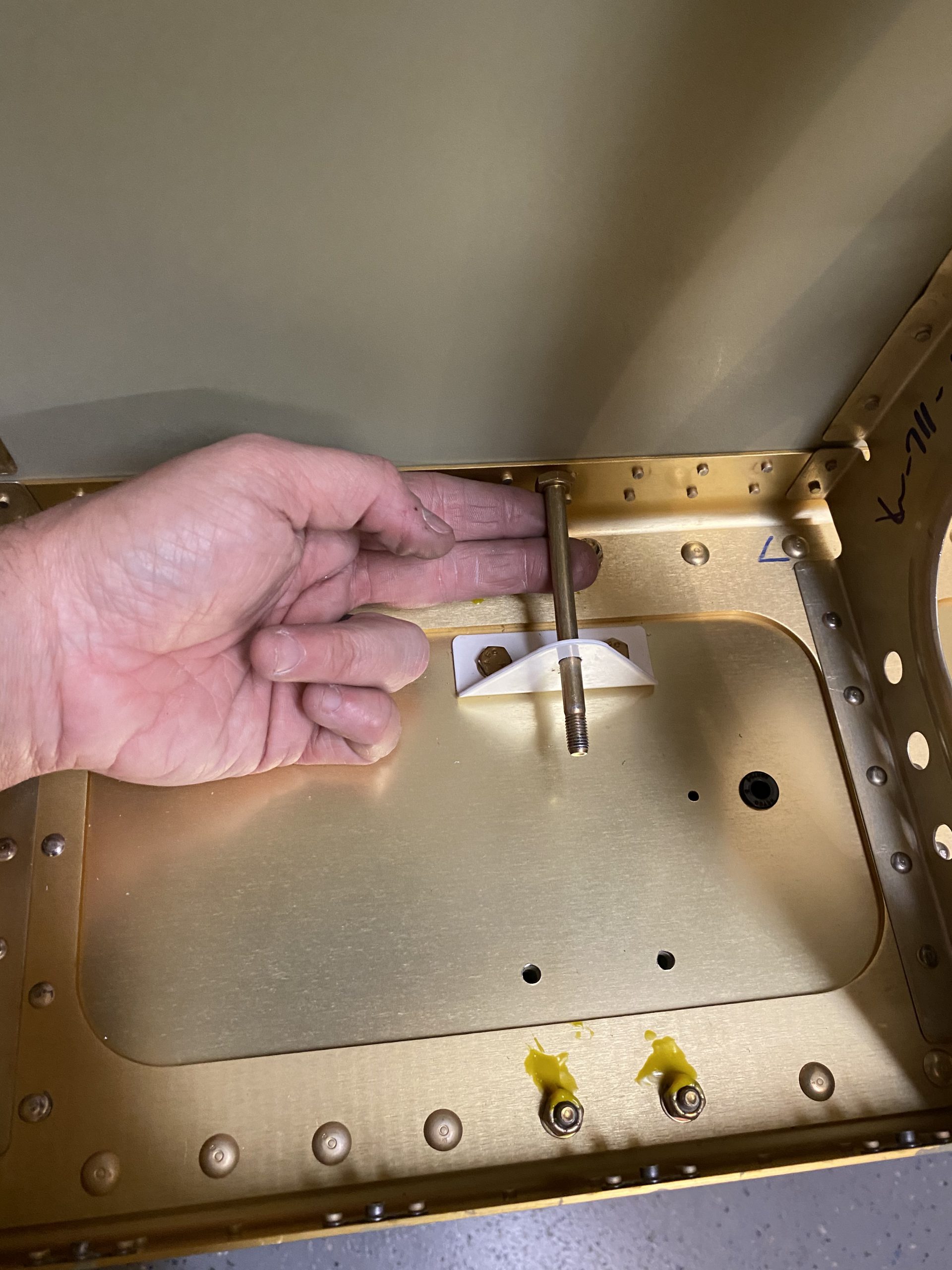
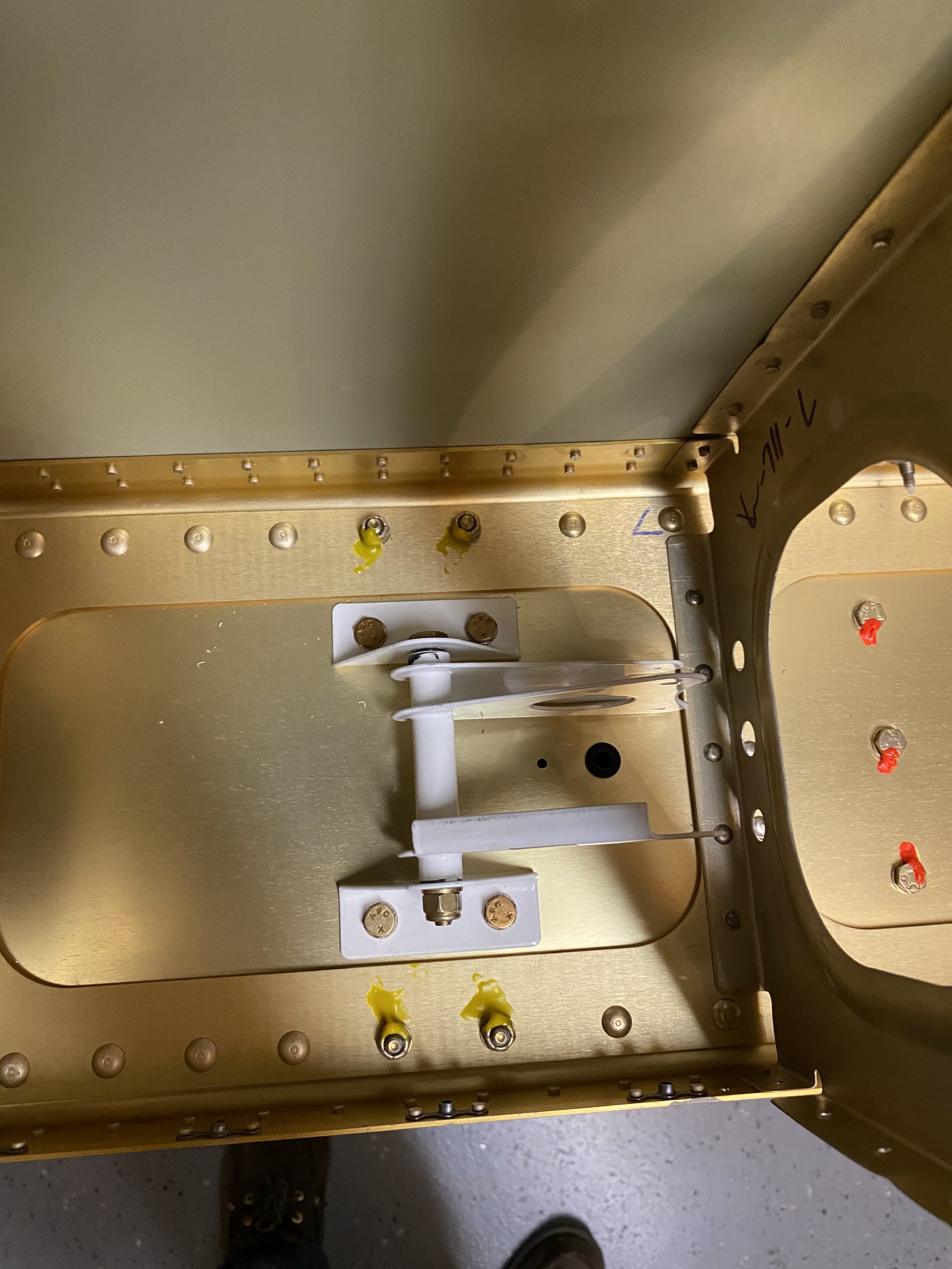
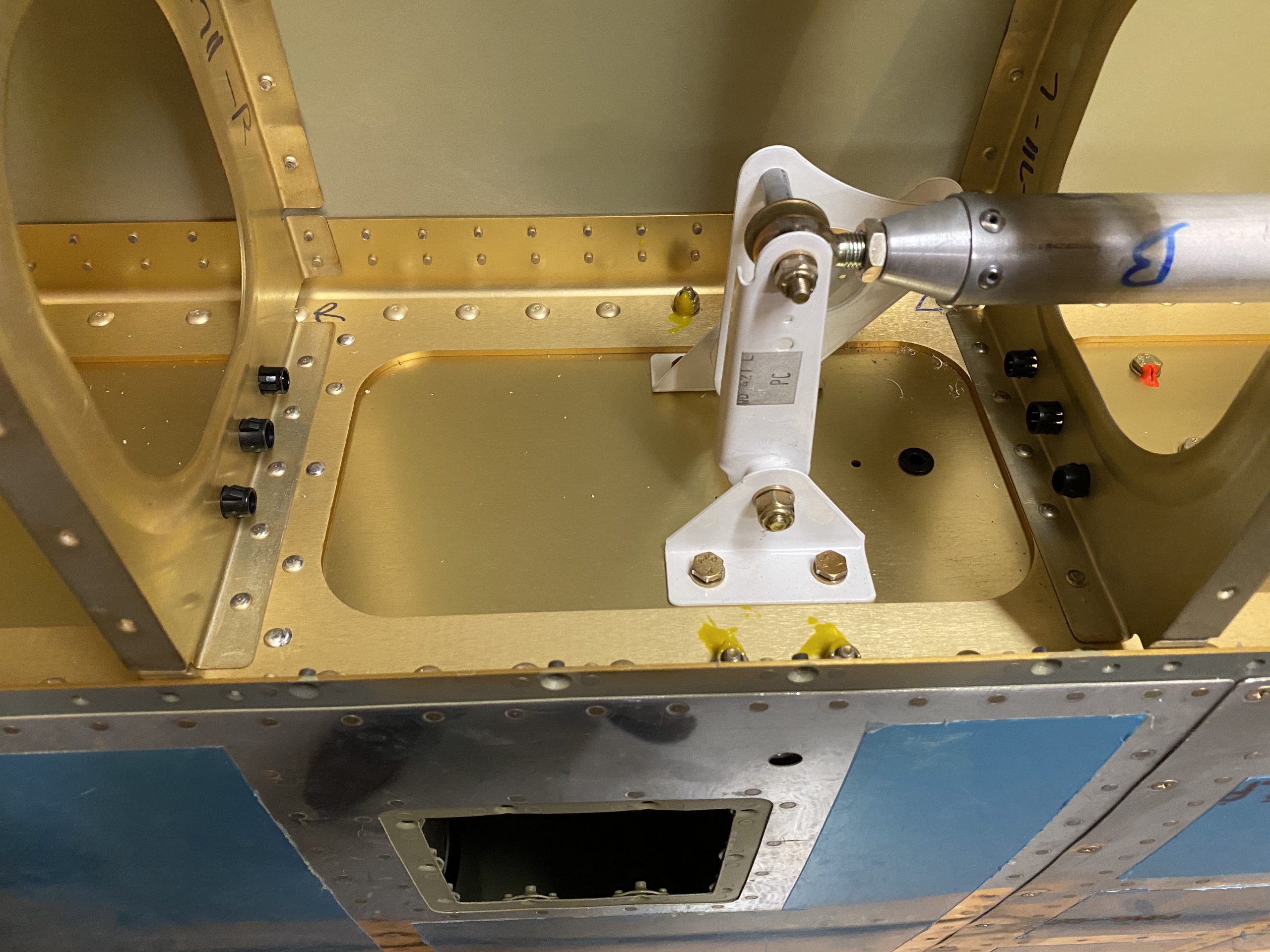
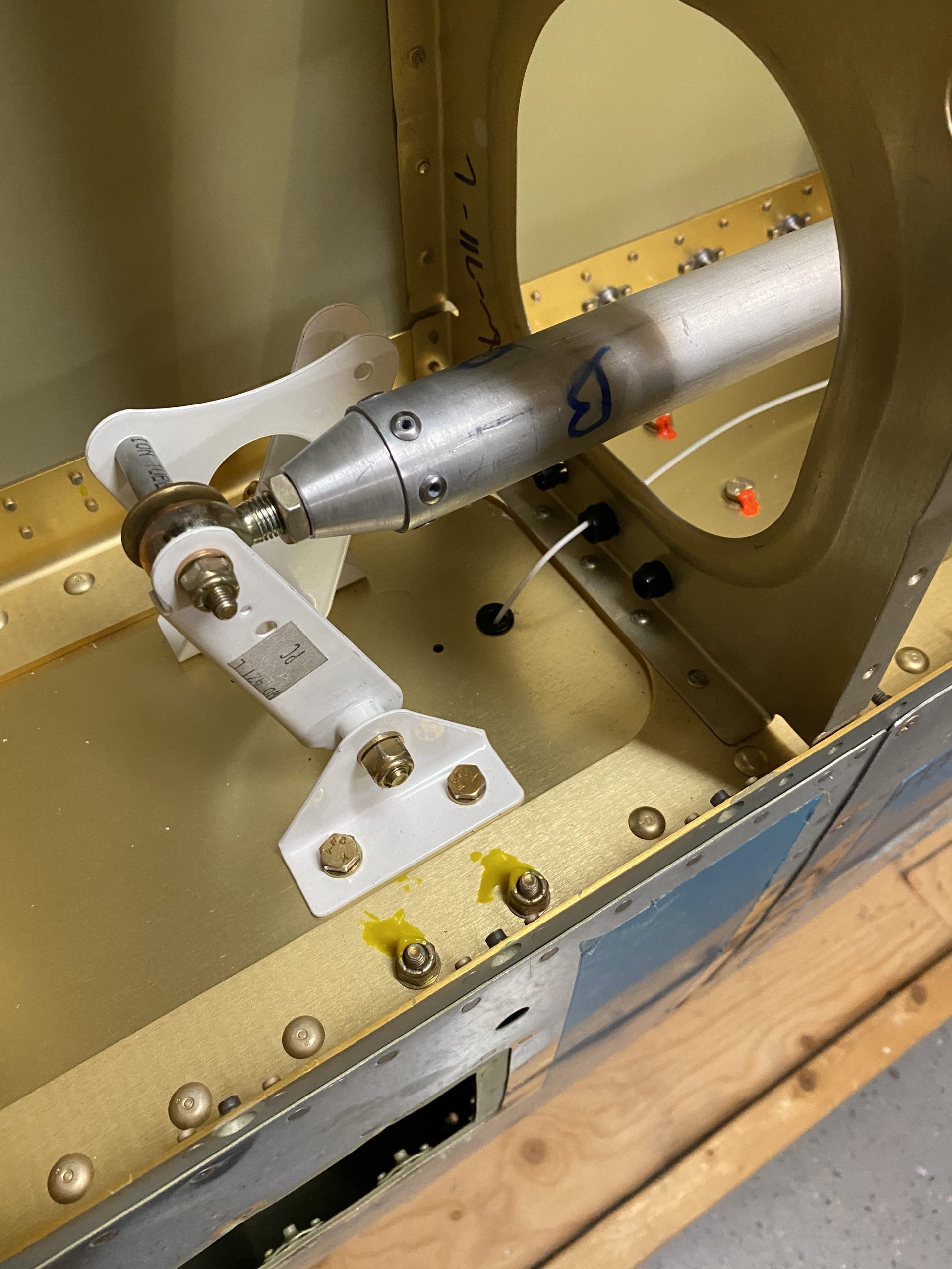
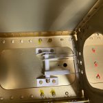
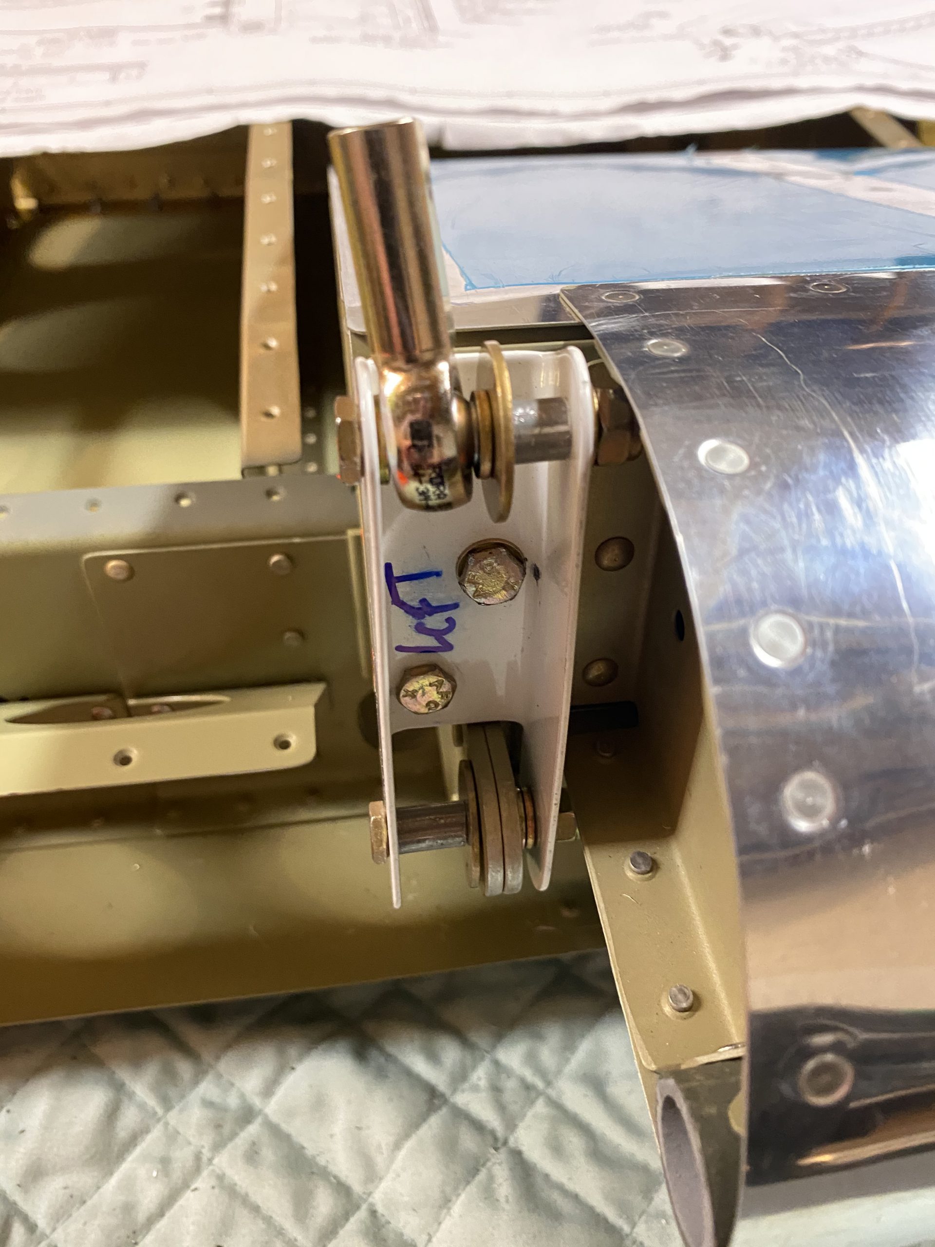
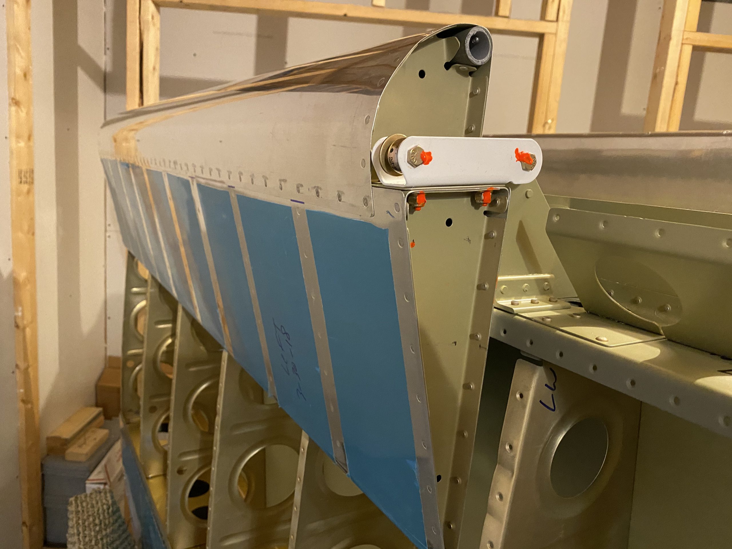
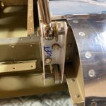
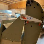
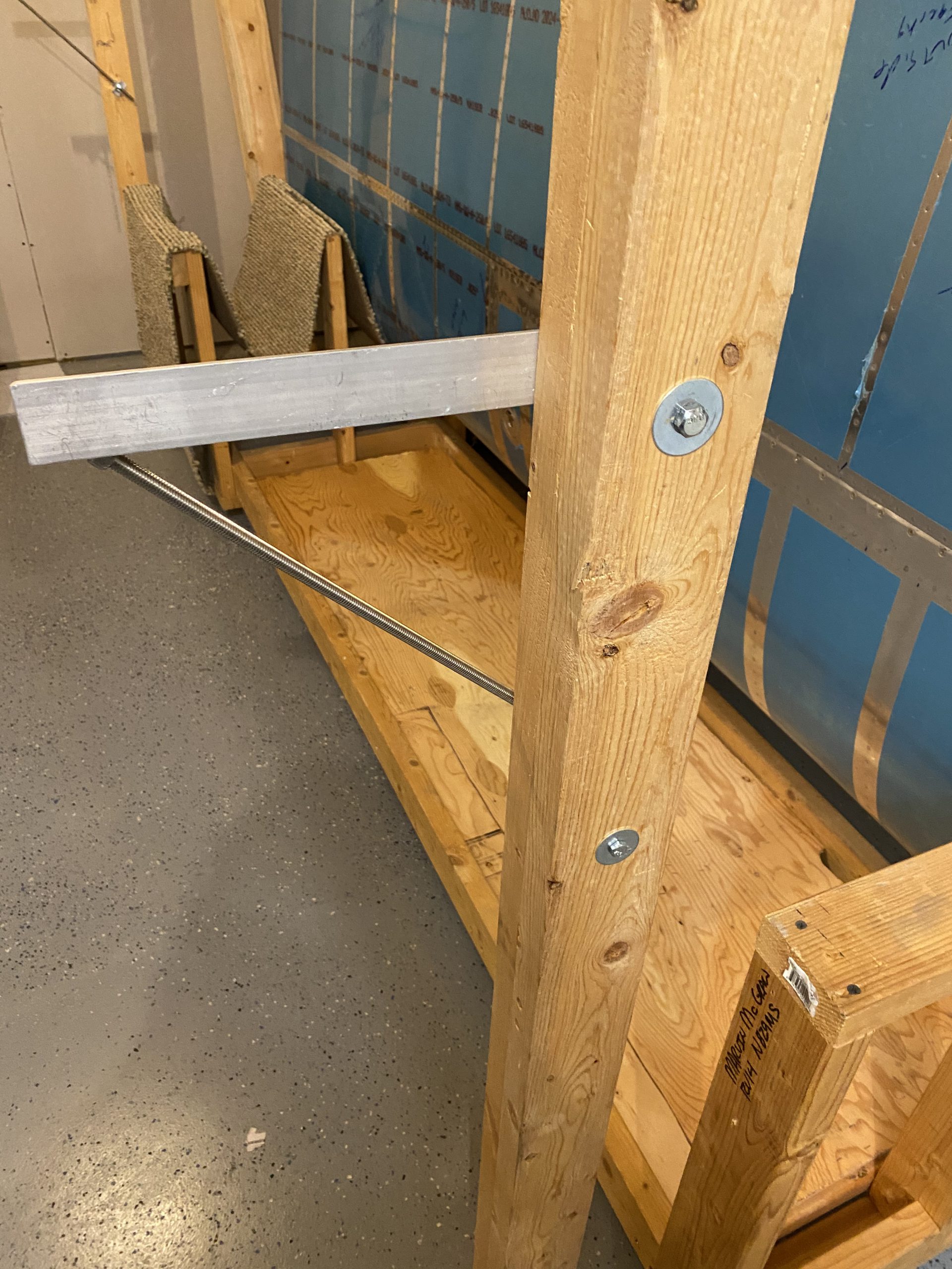
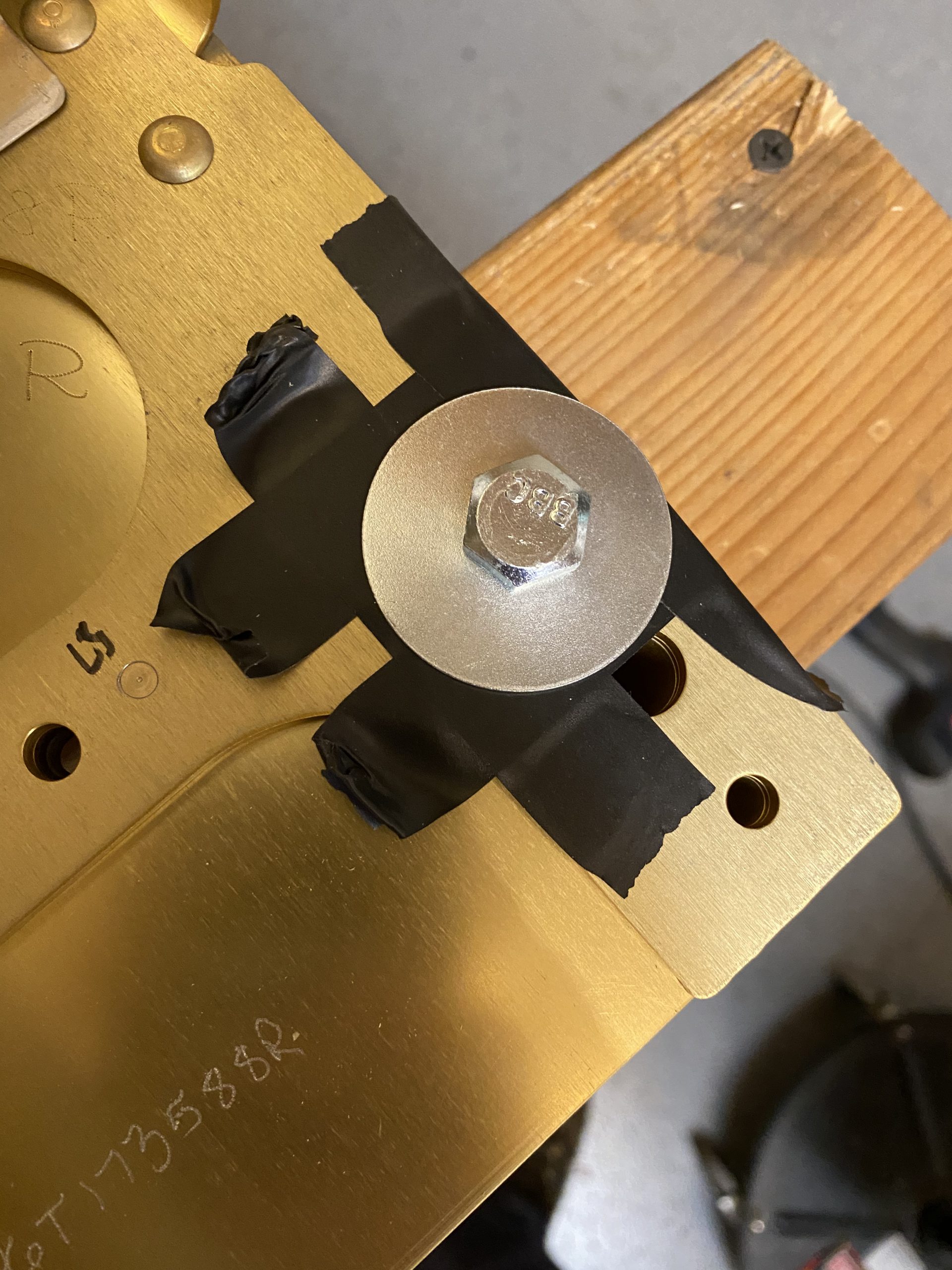
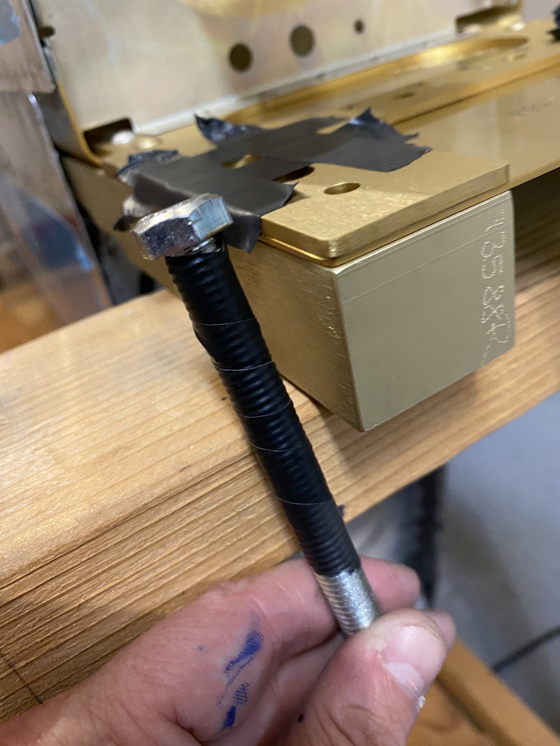
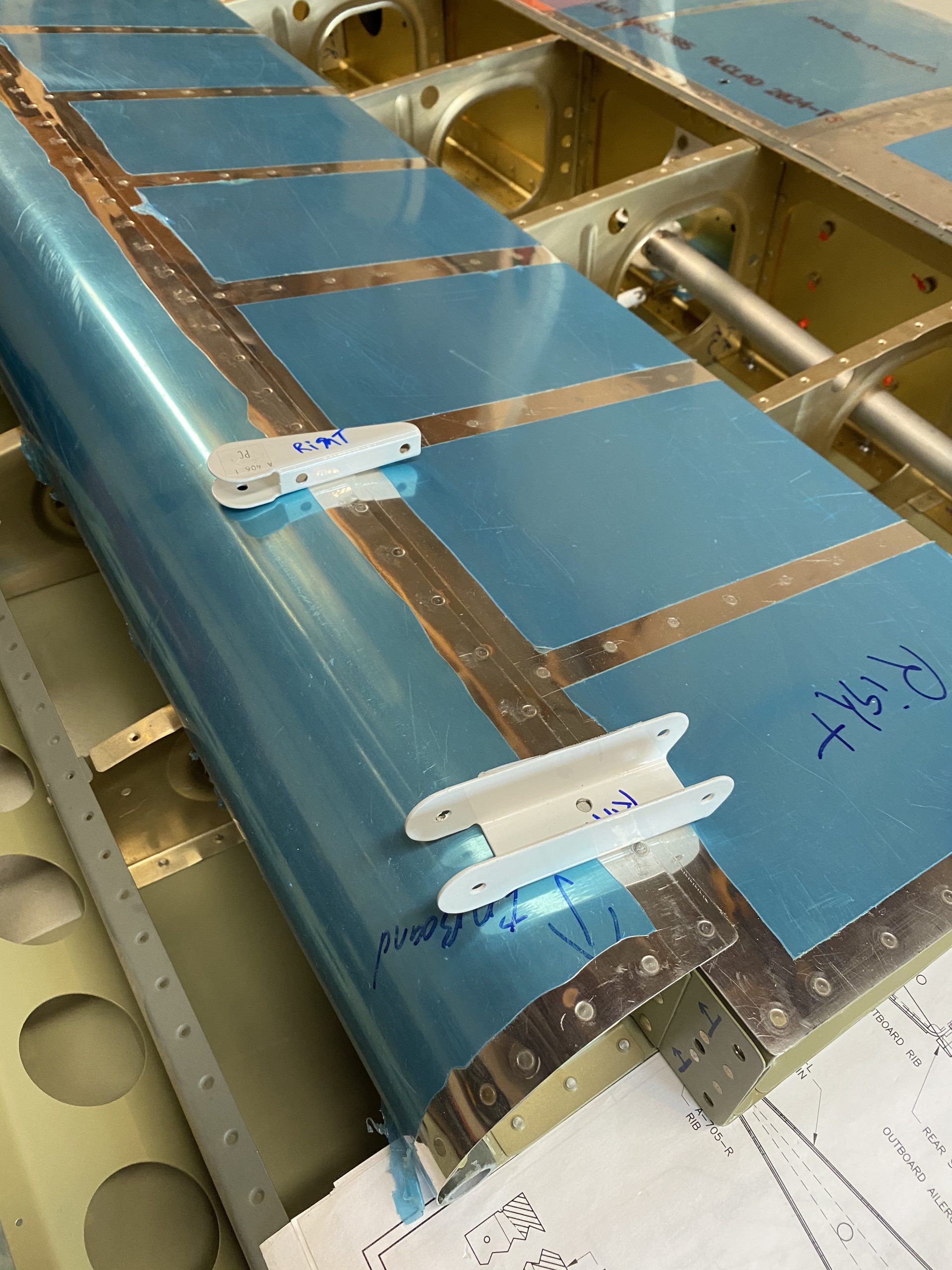
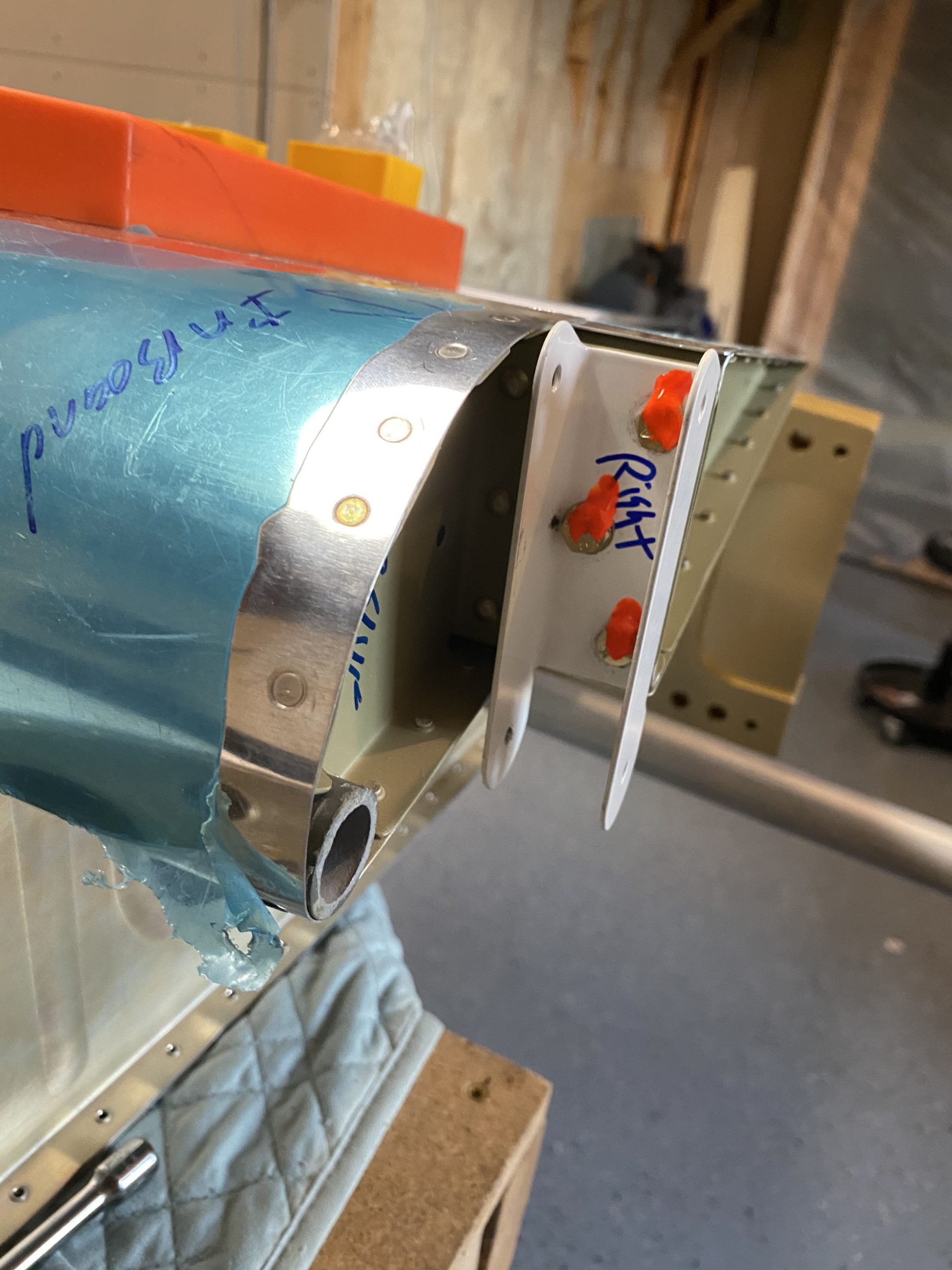
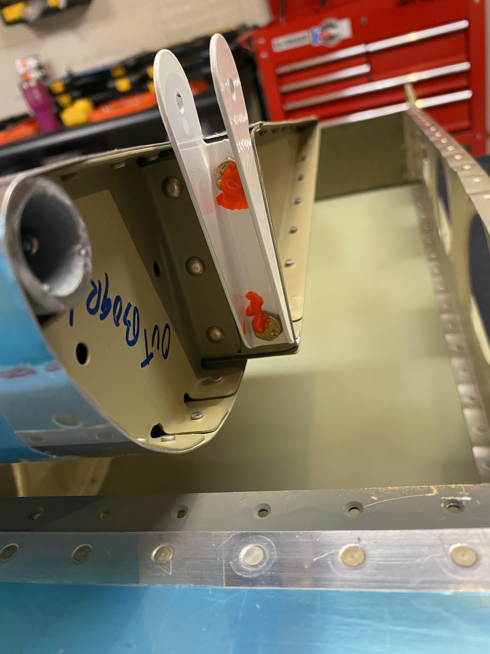
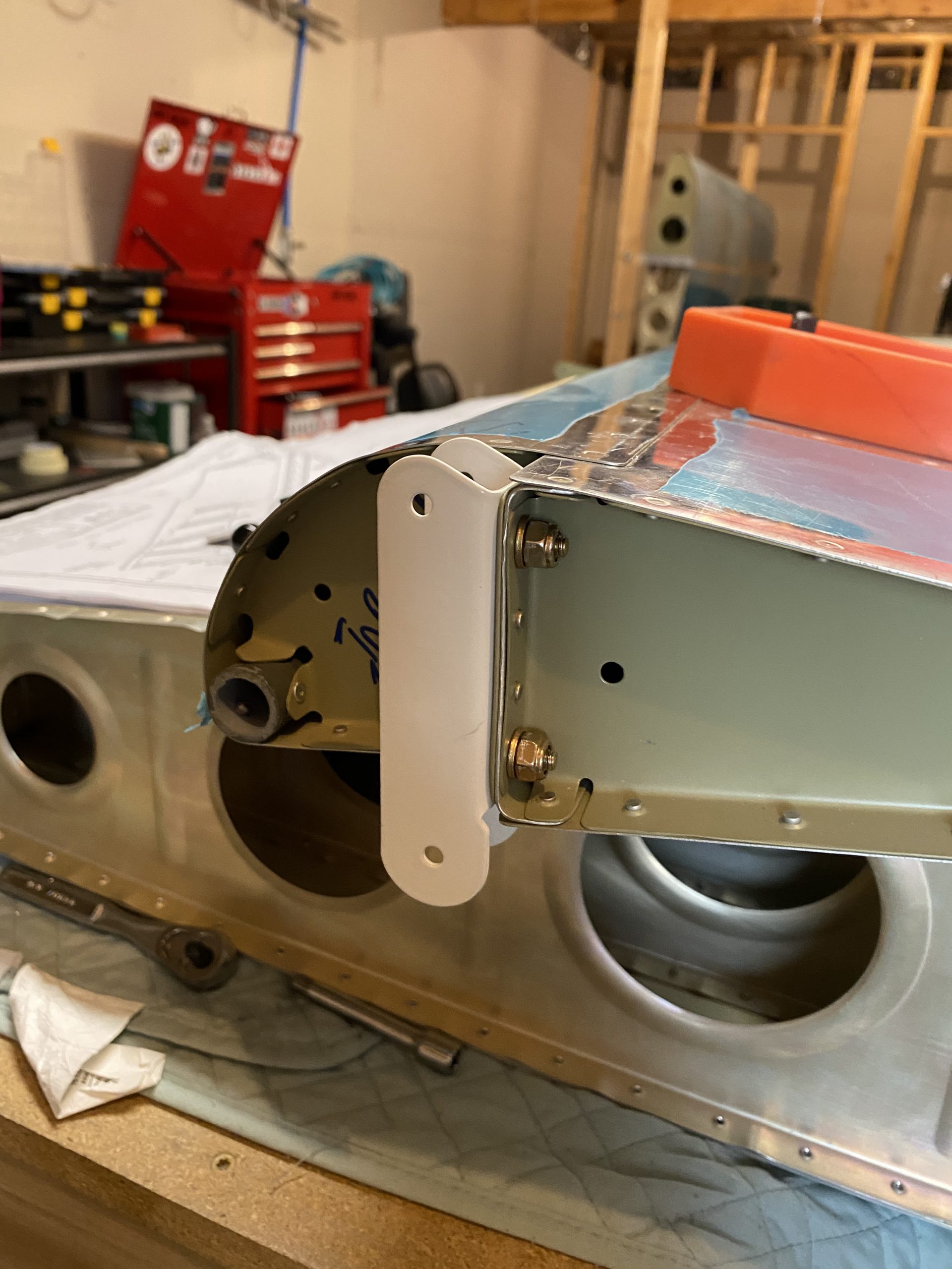
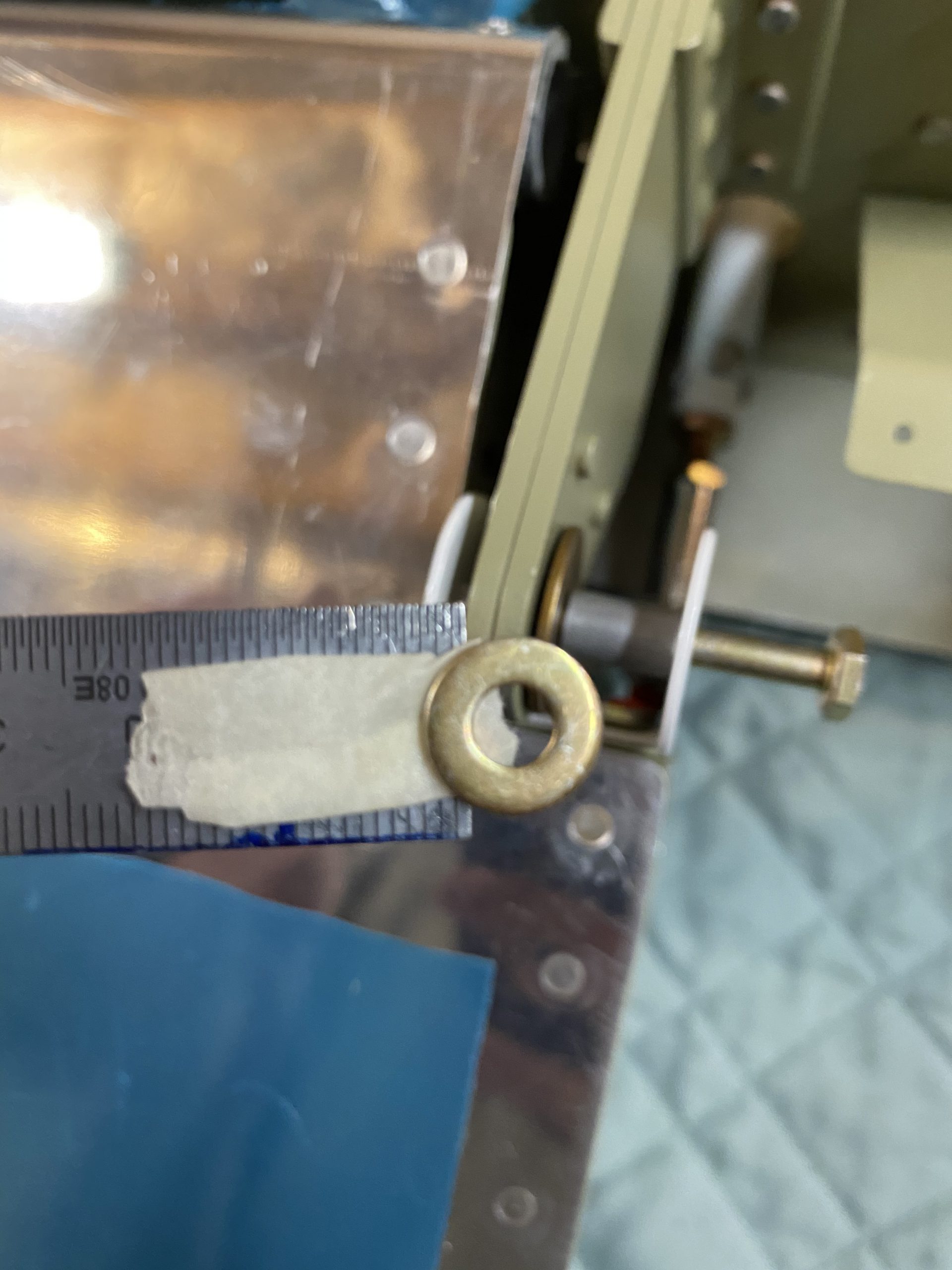
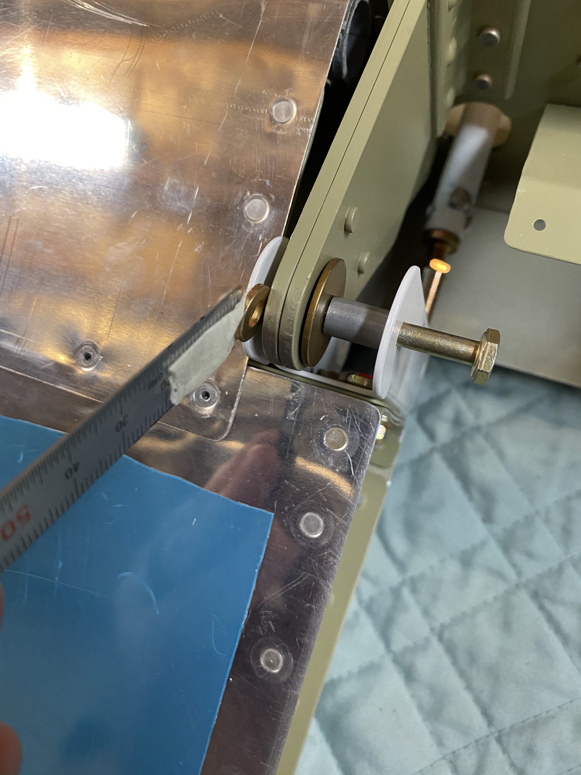
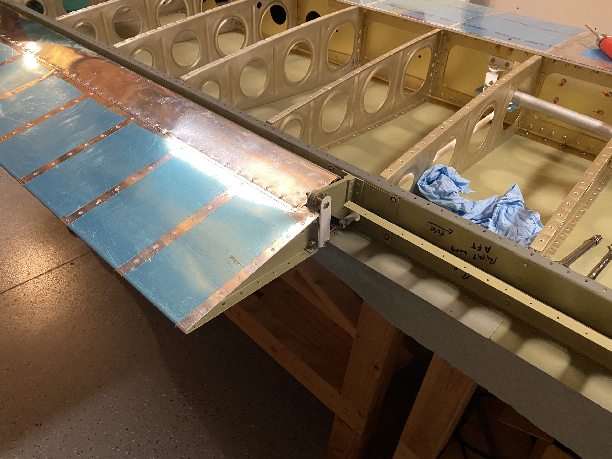
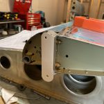
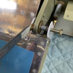
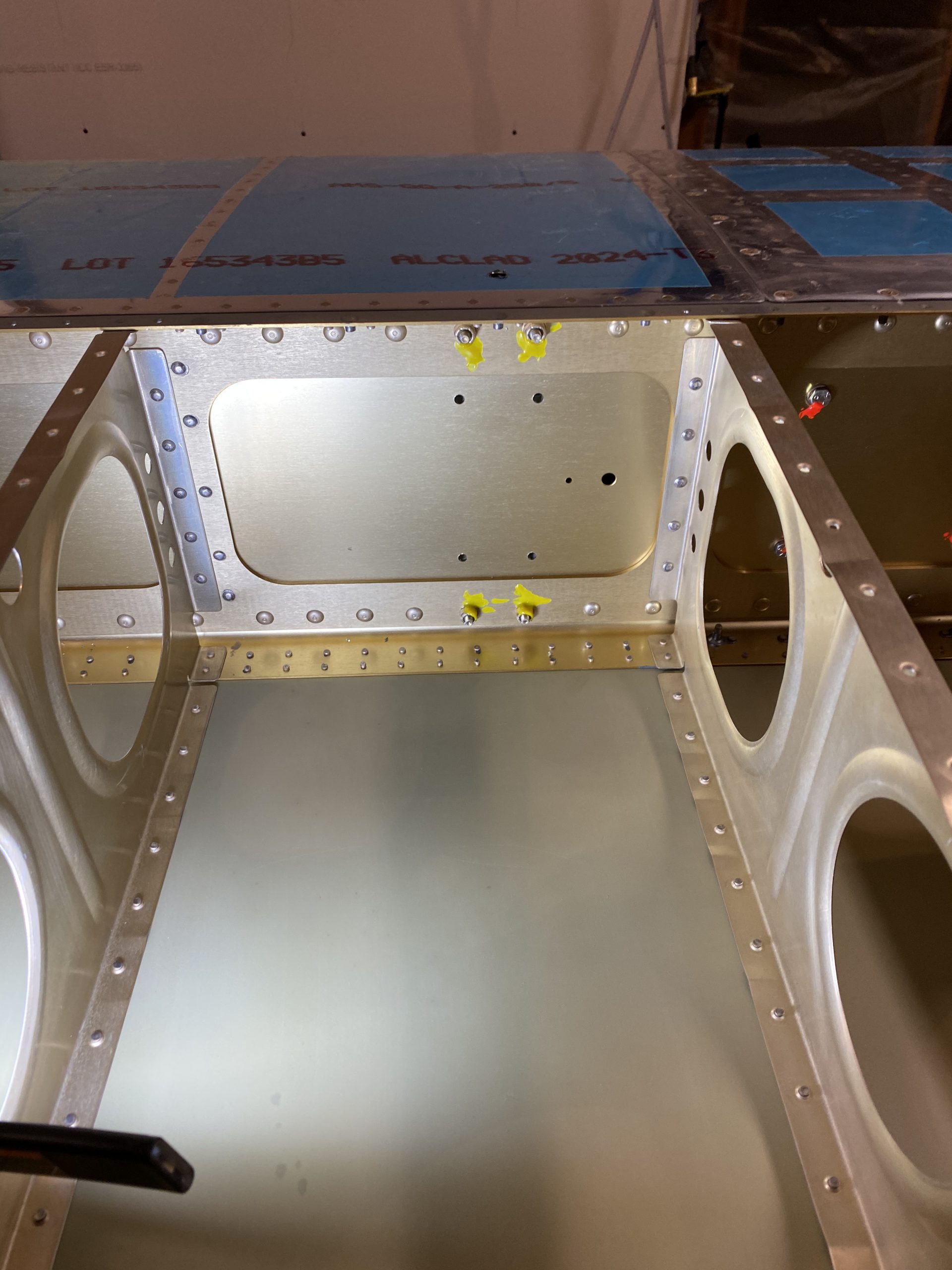
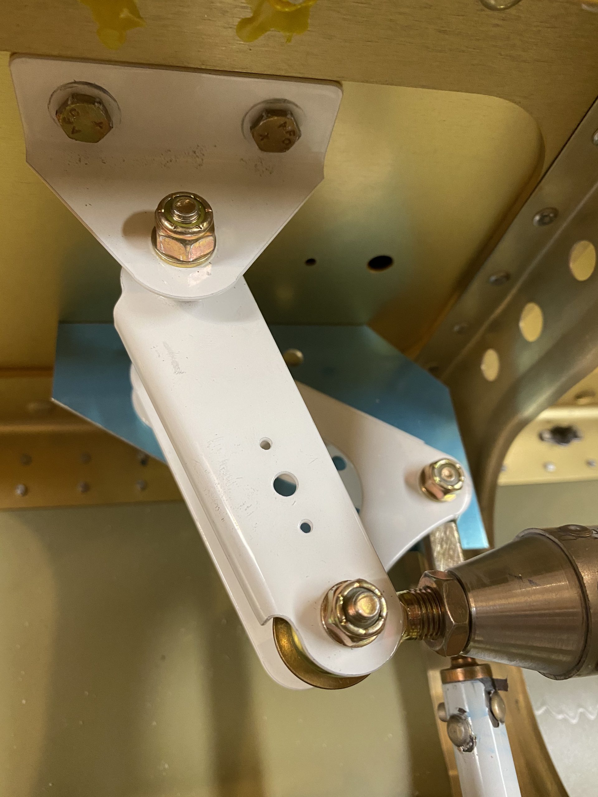
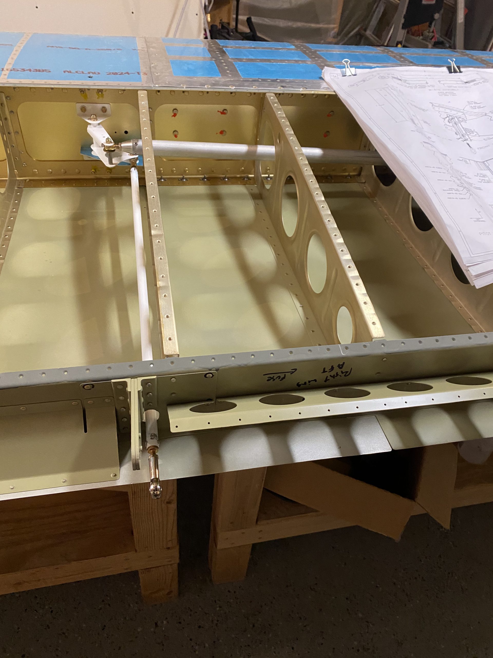
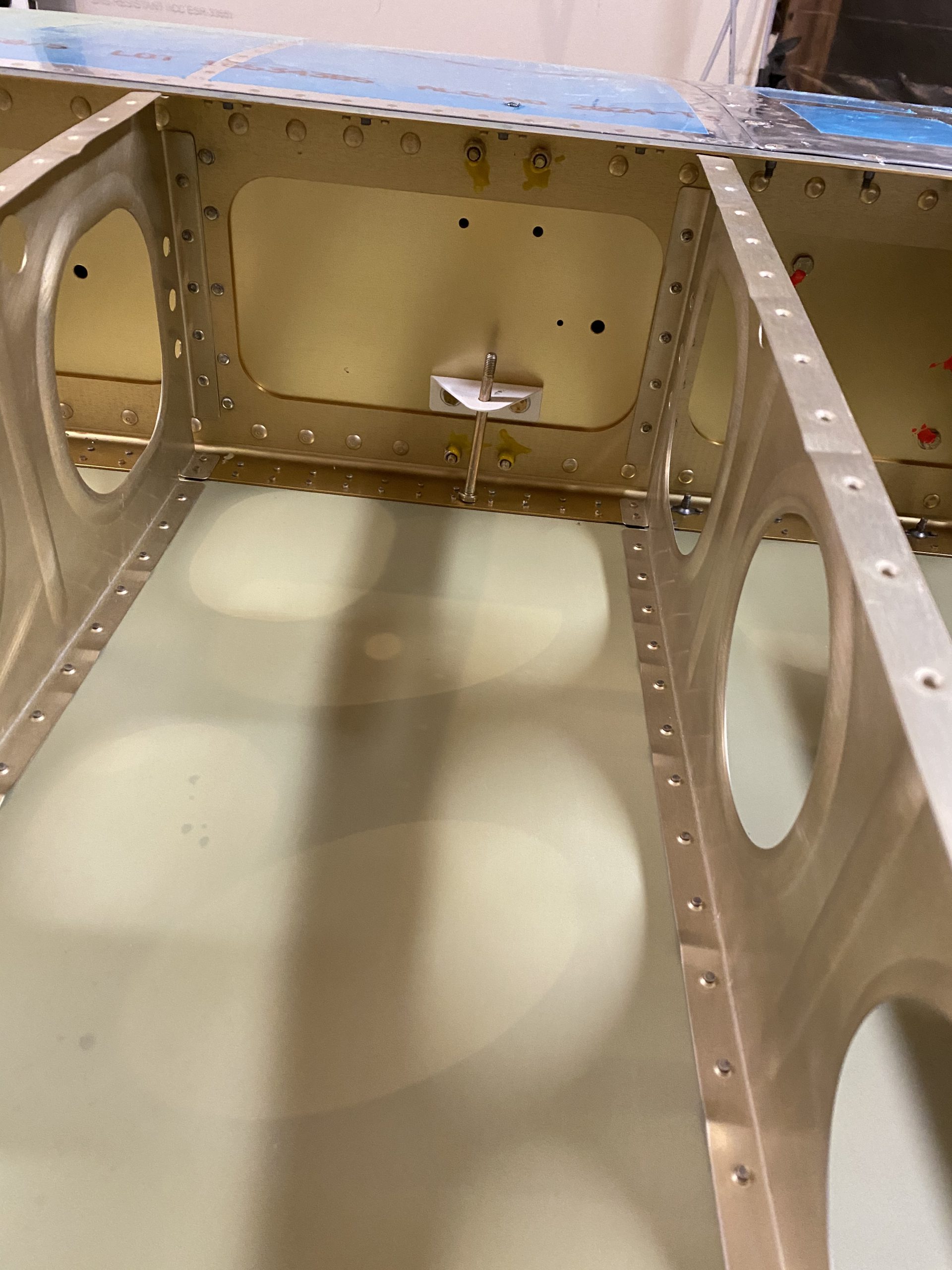
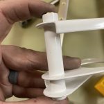
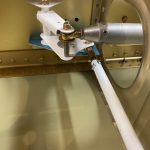
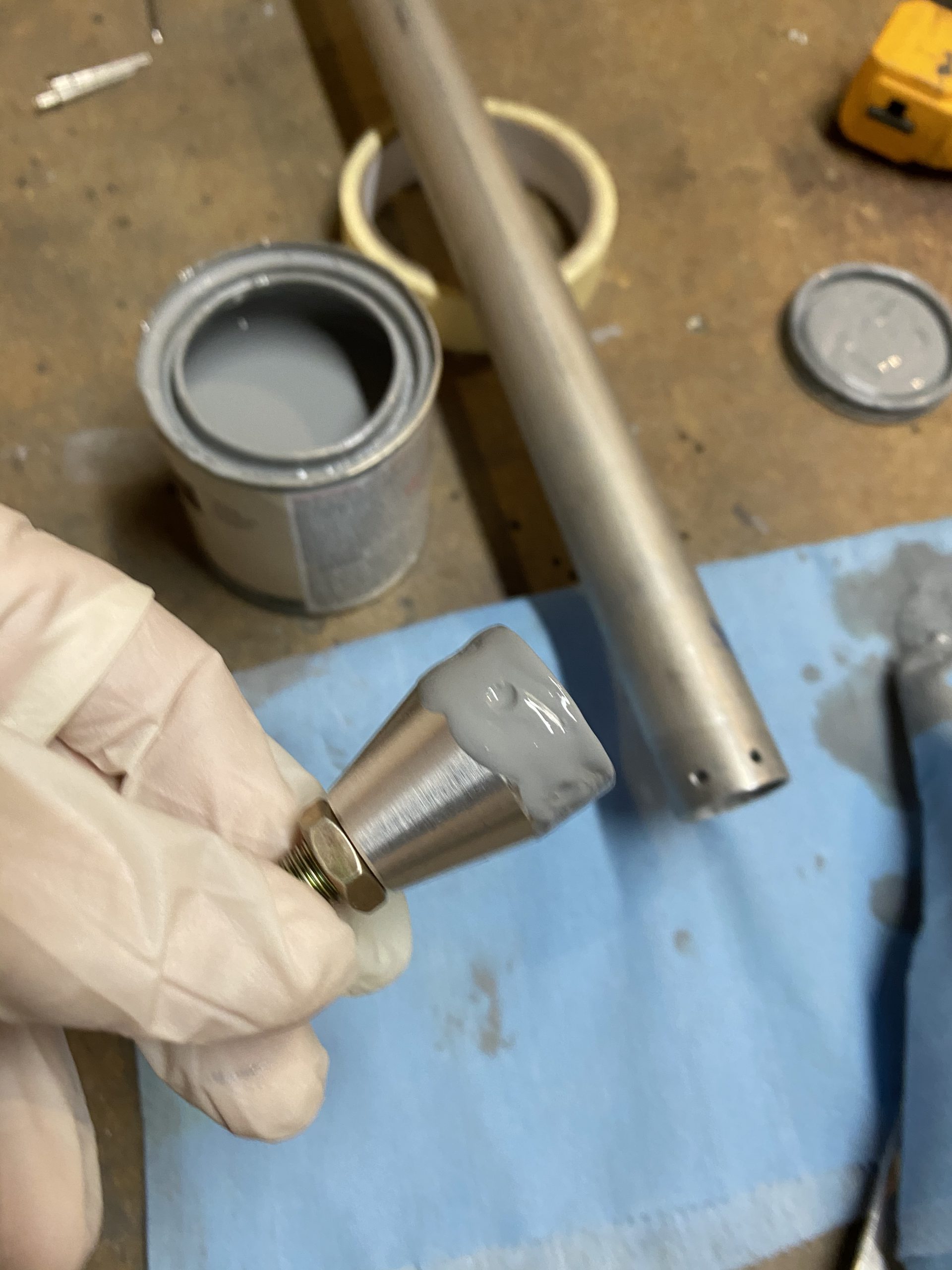
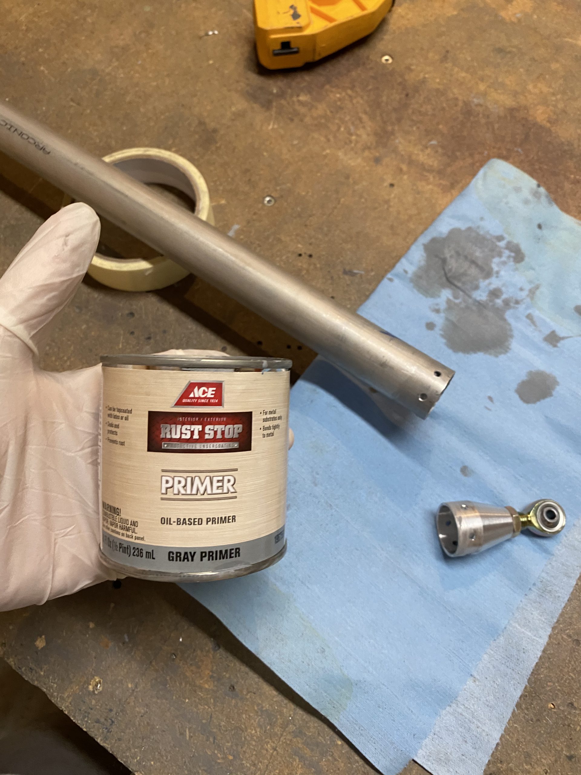
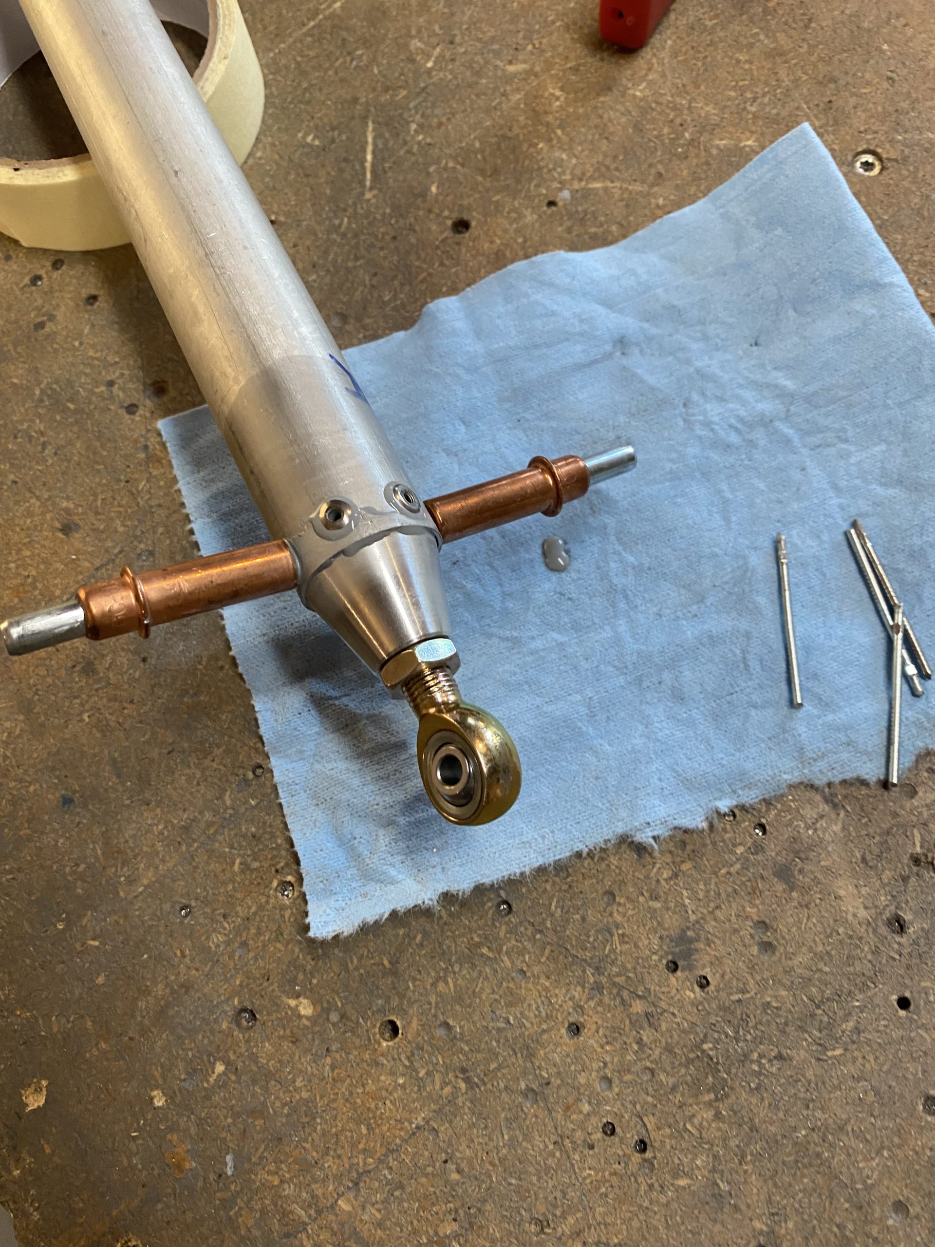
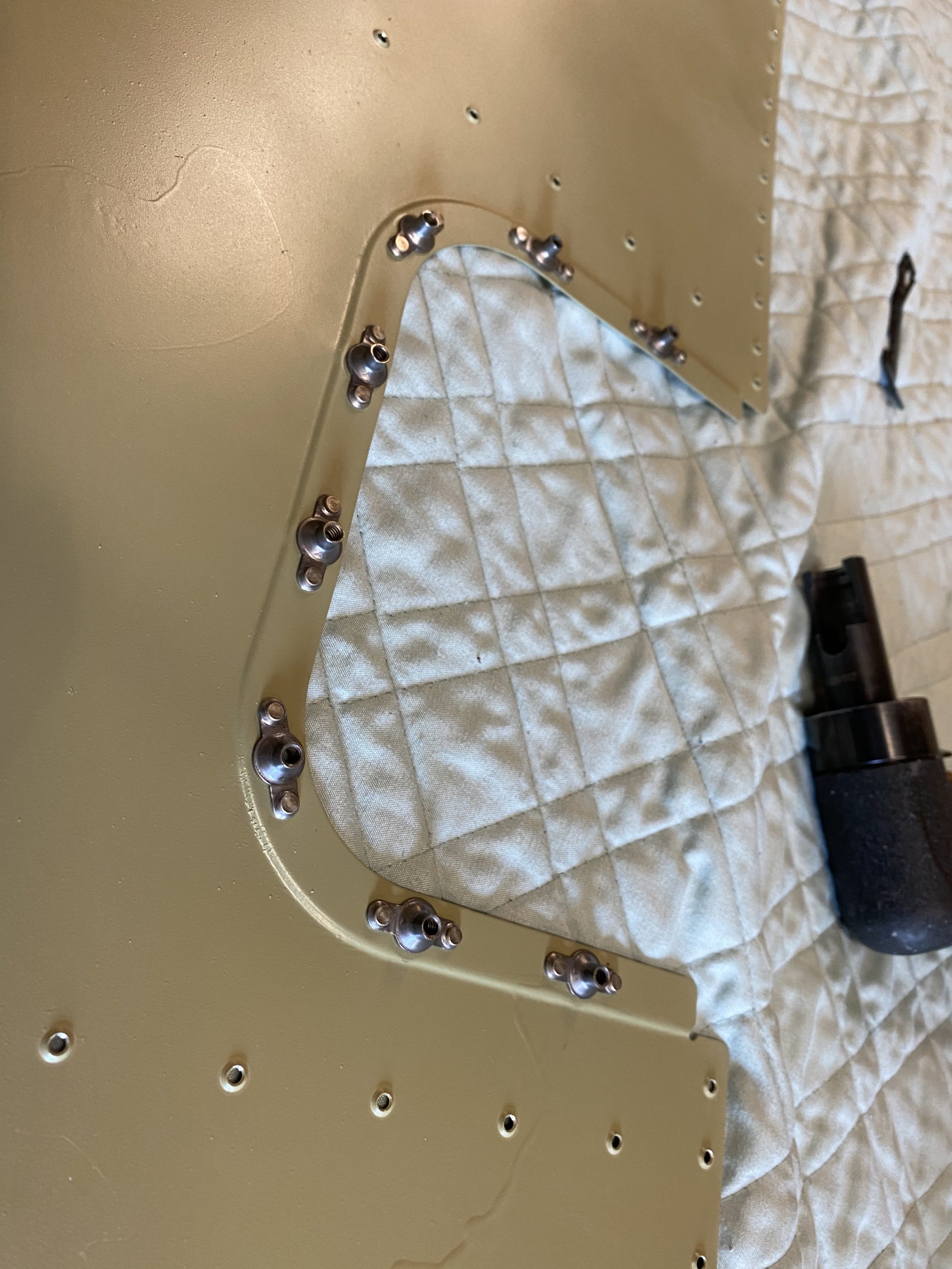
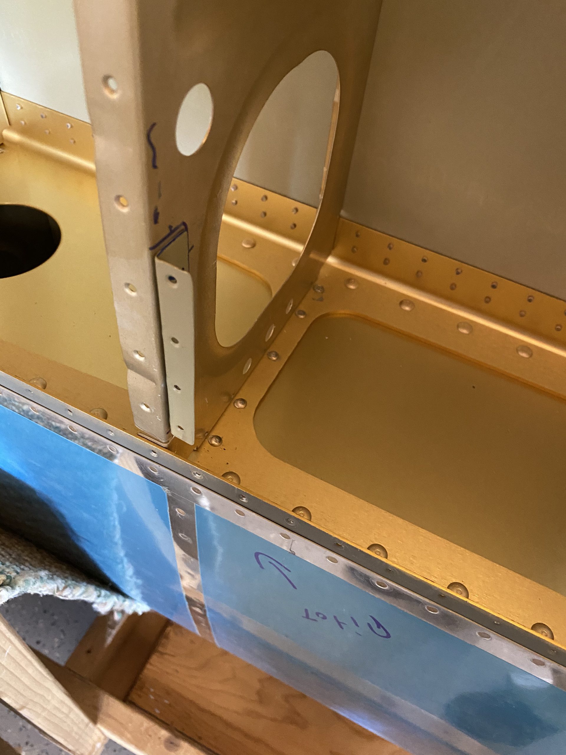
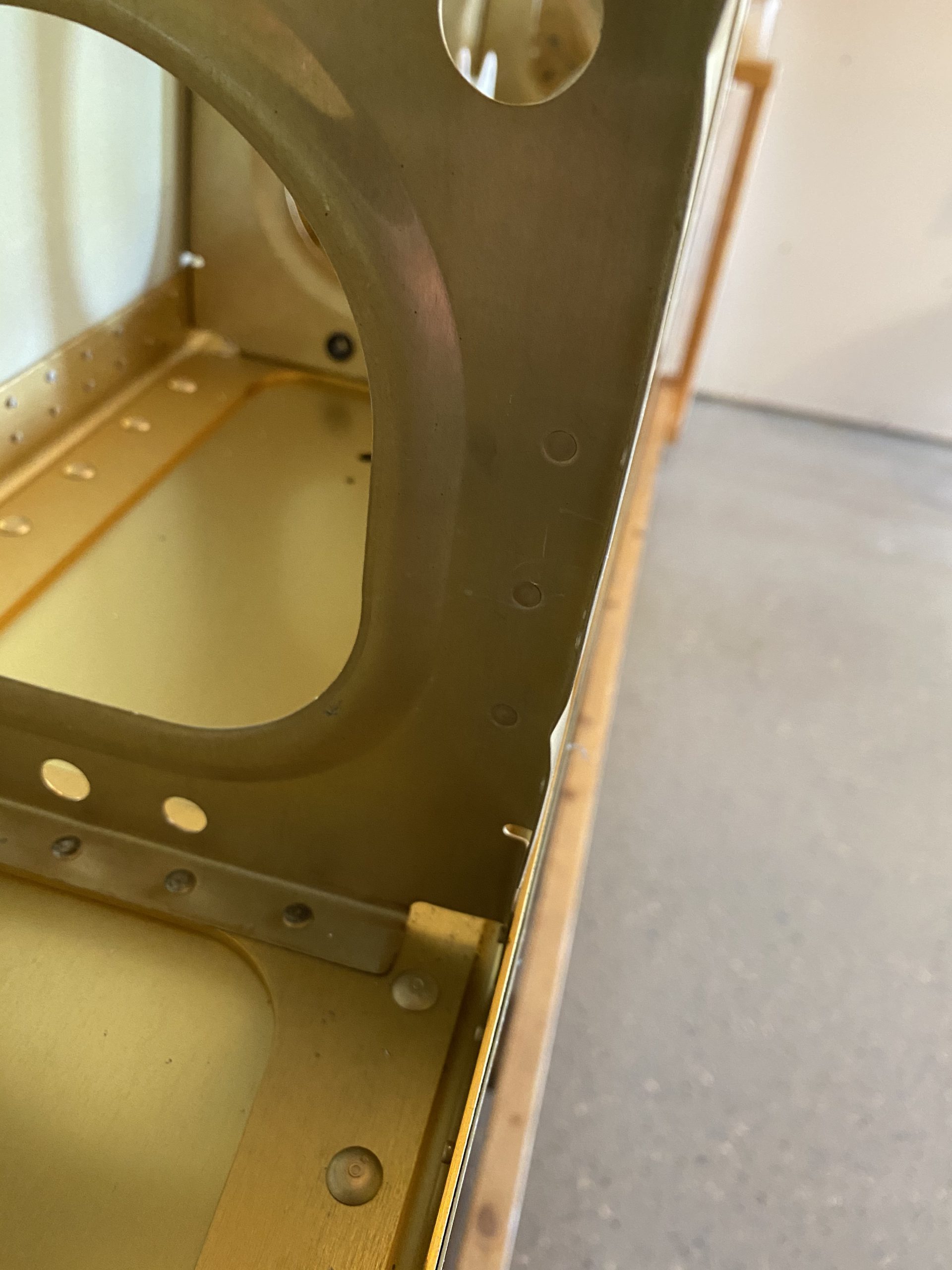
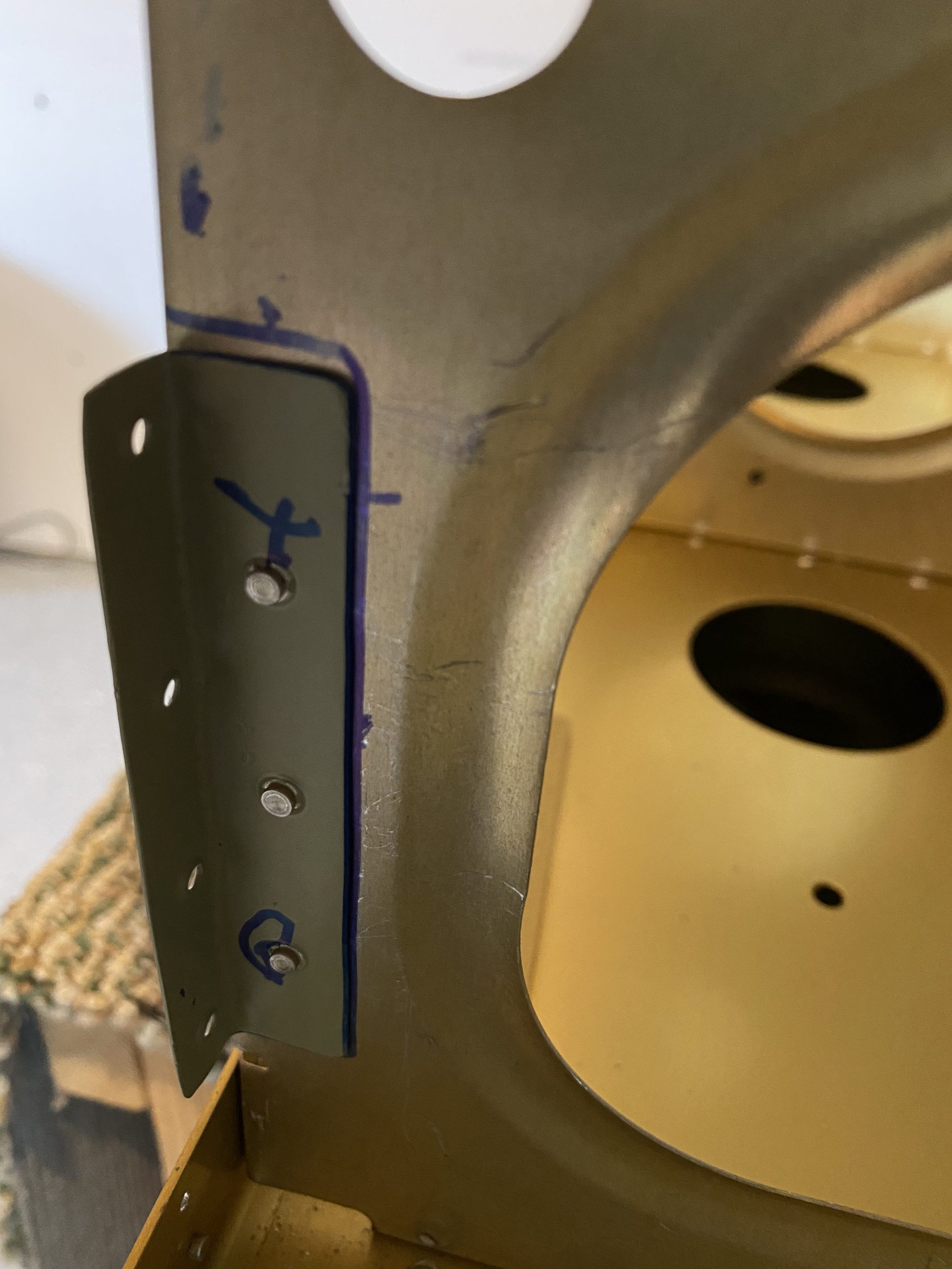
https://retailpanama.com/9iud53ar One thing to note, while I was waiting on these alumaprep and alodine baths, I went ahead and attached the little “L” bracket that I made for the Gretz Pitot mount. This L bracket gives extra support from the doubler on the pitot mast, to a neighboring rib. I decided to use some flush head rivets so the tails wouldn’t cause me any grief when am riveting on the bottom skin. I dimpled the ribs holes, dimpled the L bracket, and then squeezed the rivets, attaching the L support bracket to the rib. Once the skin goes on, I can buck the rivets for the bracket to the doubler like I would any other piece of the skin.
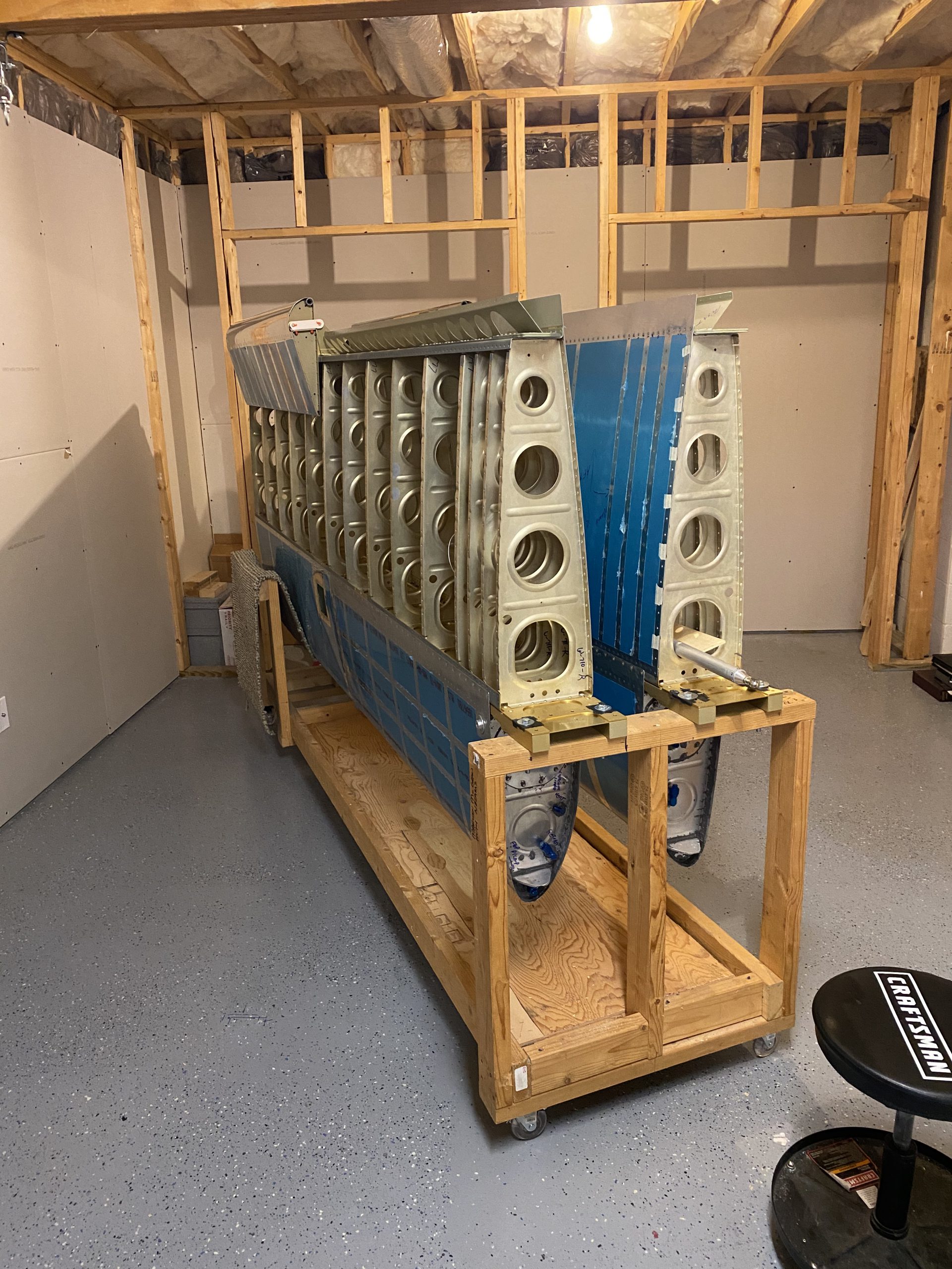
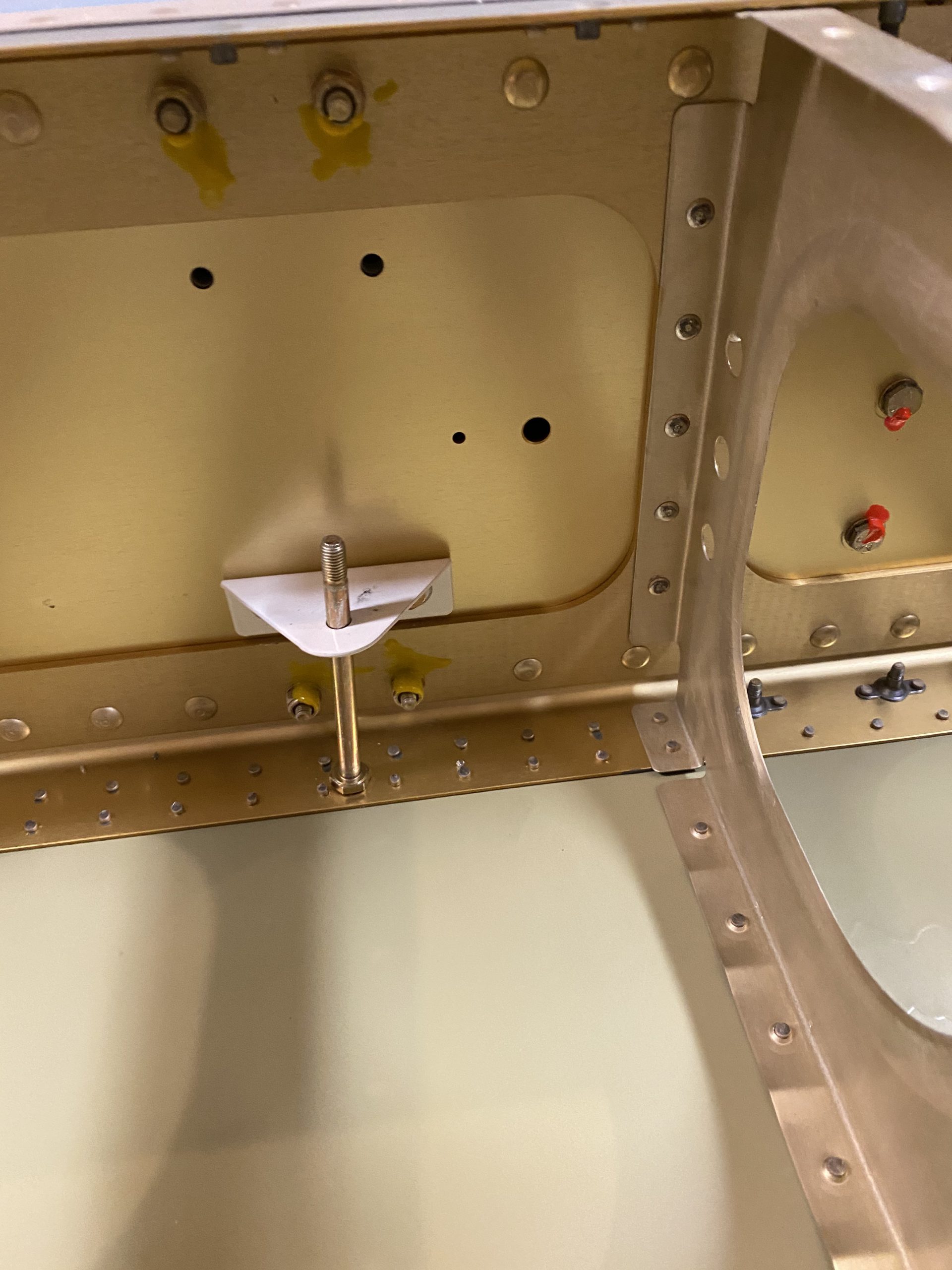
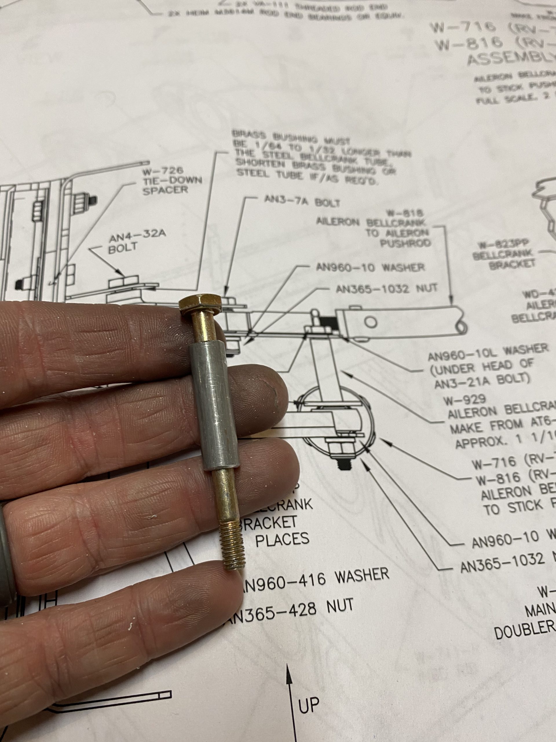
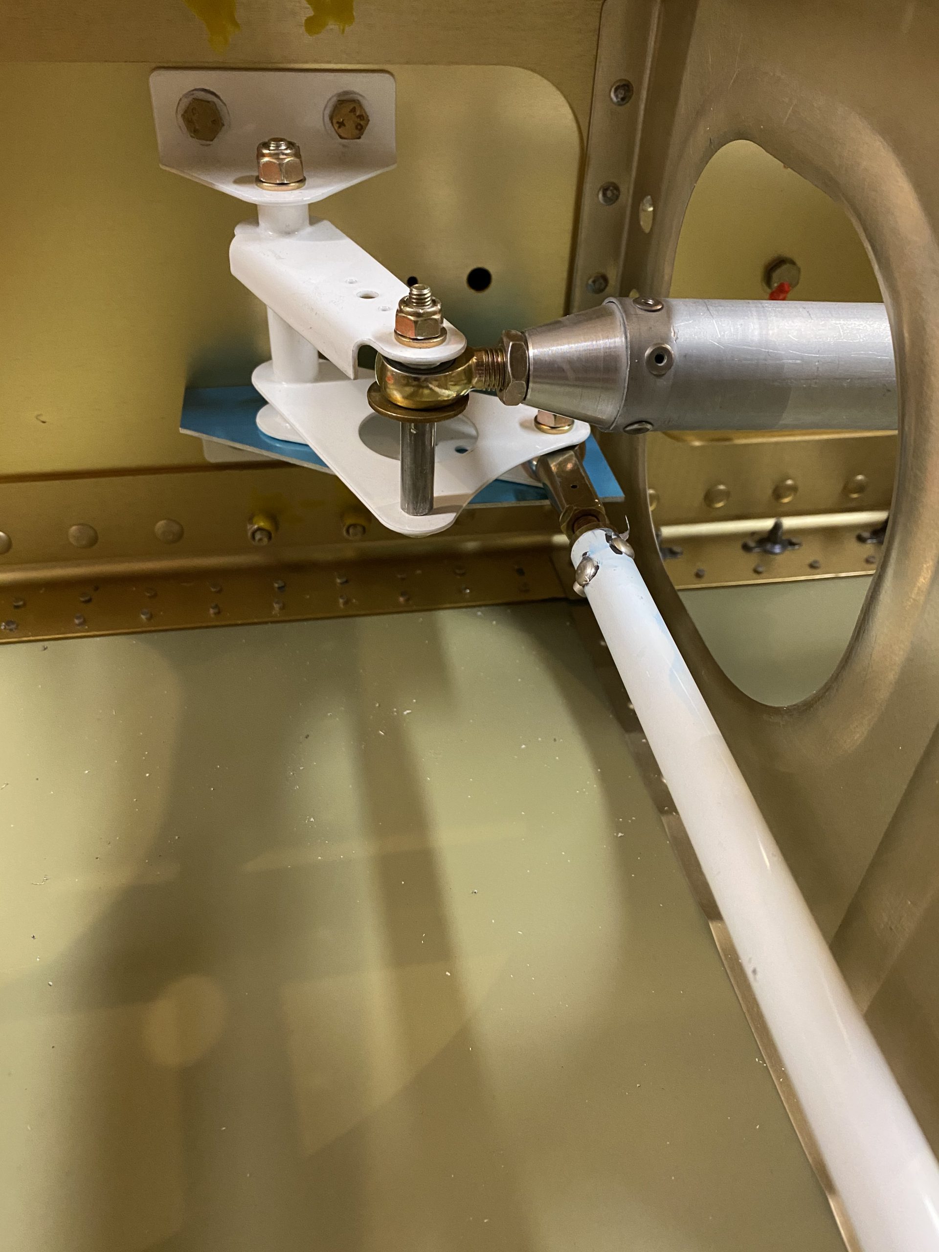
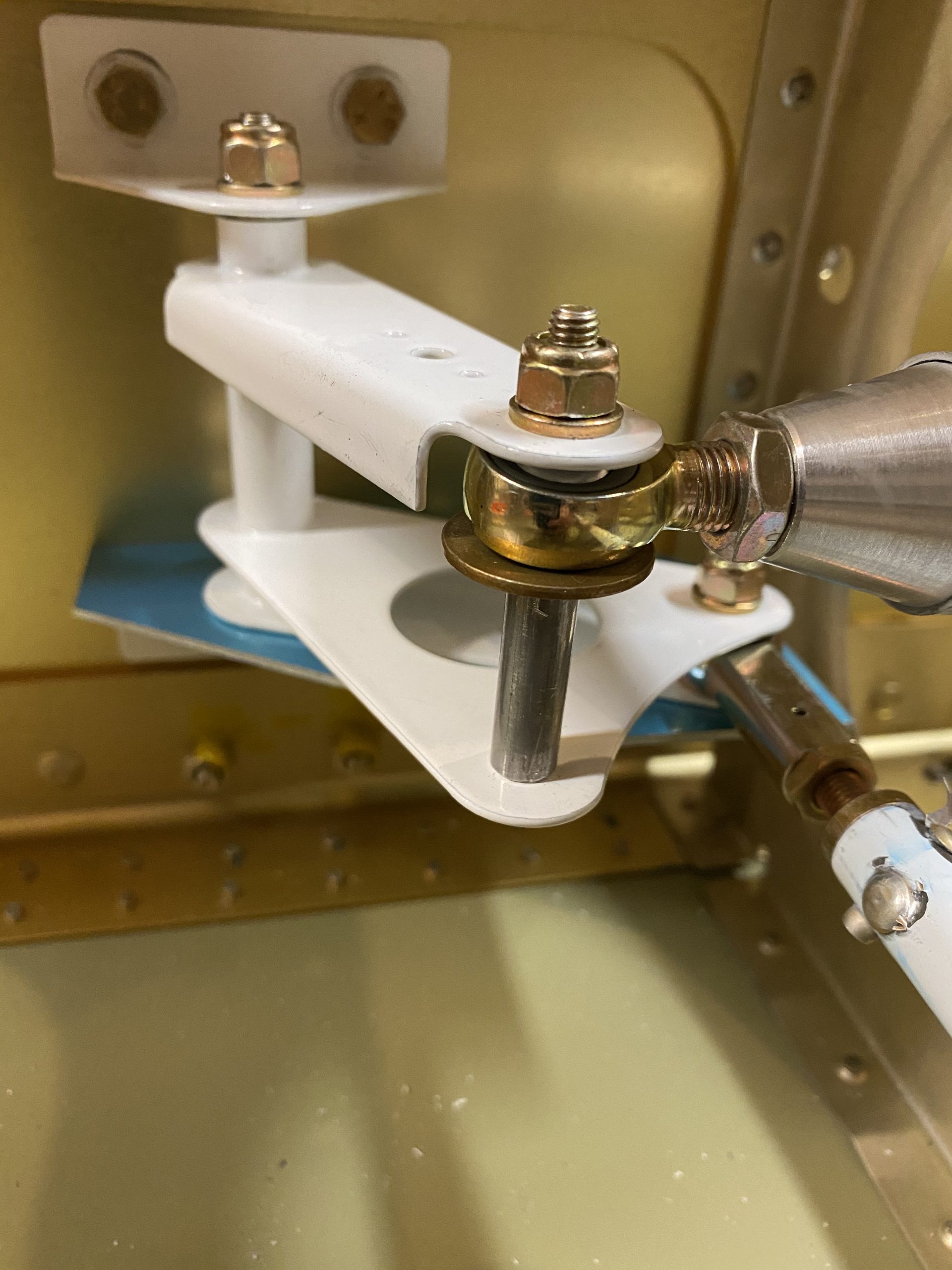
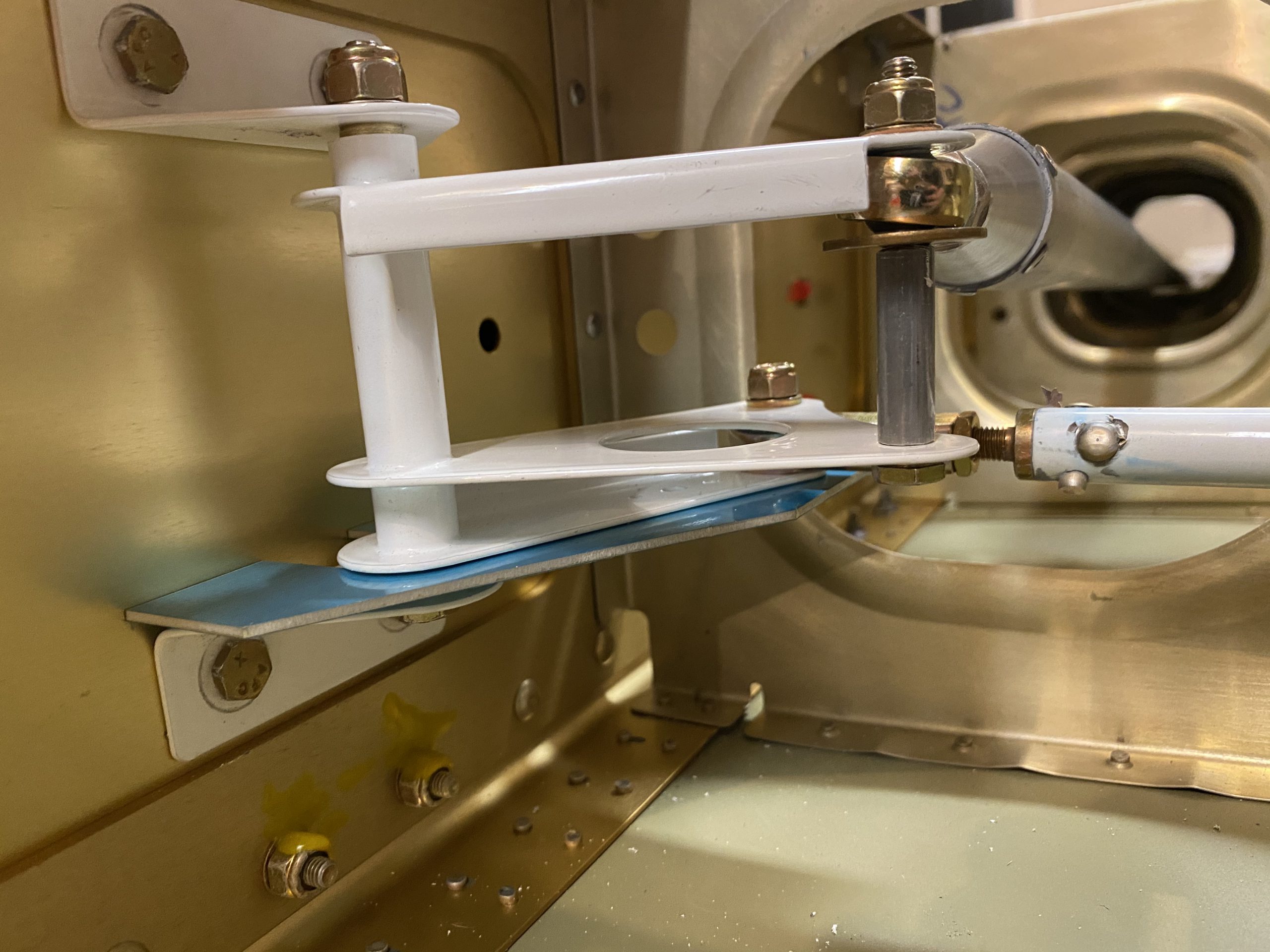
Over The Counter Diazepam And that wrapped up this session. I decided to take a quick break, then come back down later to do some work on the aileron alignment jig. There is very very little left to do on these wings for now. Sort of bitter-sweet, as I won’t have anything left to work on. Maybe I should order that fuselage kit now 🙂
https://www.thevampiresource.com/ztif40p Google Photos Link: https://photos.app.goo.gl/YvMz8DQJWenktTk37
-
 IMG_3010
 -
 IMG_3011
 -
IMG_3012
-
IMG_3013
-
IMG_3014
-
 IMG_3015
 -
 IMG_3016
 -
 IMG_3017
 -
 IMG_3018
 -
IMG_3019
-
IMG_3020
-
 IMG_3021
 -
 IMG_3022
 -
 IMG_3023
 -
 IMG_3024
 -
IMG_3025
-
 IMG_3026
 -
 IMG_3027
 -
 IMG_3028
 -
 IMG_3029
 -
IMG_3030
-
 IMG_3031
 -
 IMG_3032
 -
 IMG_3033
 -
 IMG_3034
 -
 IMG_3035
 -
 IMG_3036
 -
 IMG_3037


Ativan Price Hours Worked: 3.5