Attaching the Right Fuel Tank

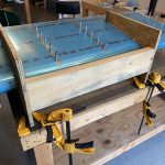
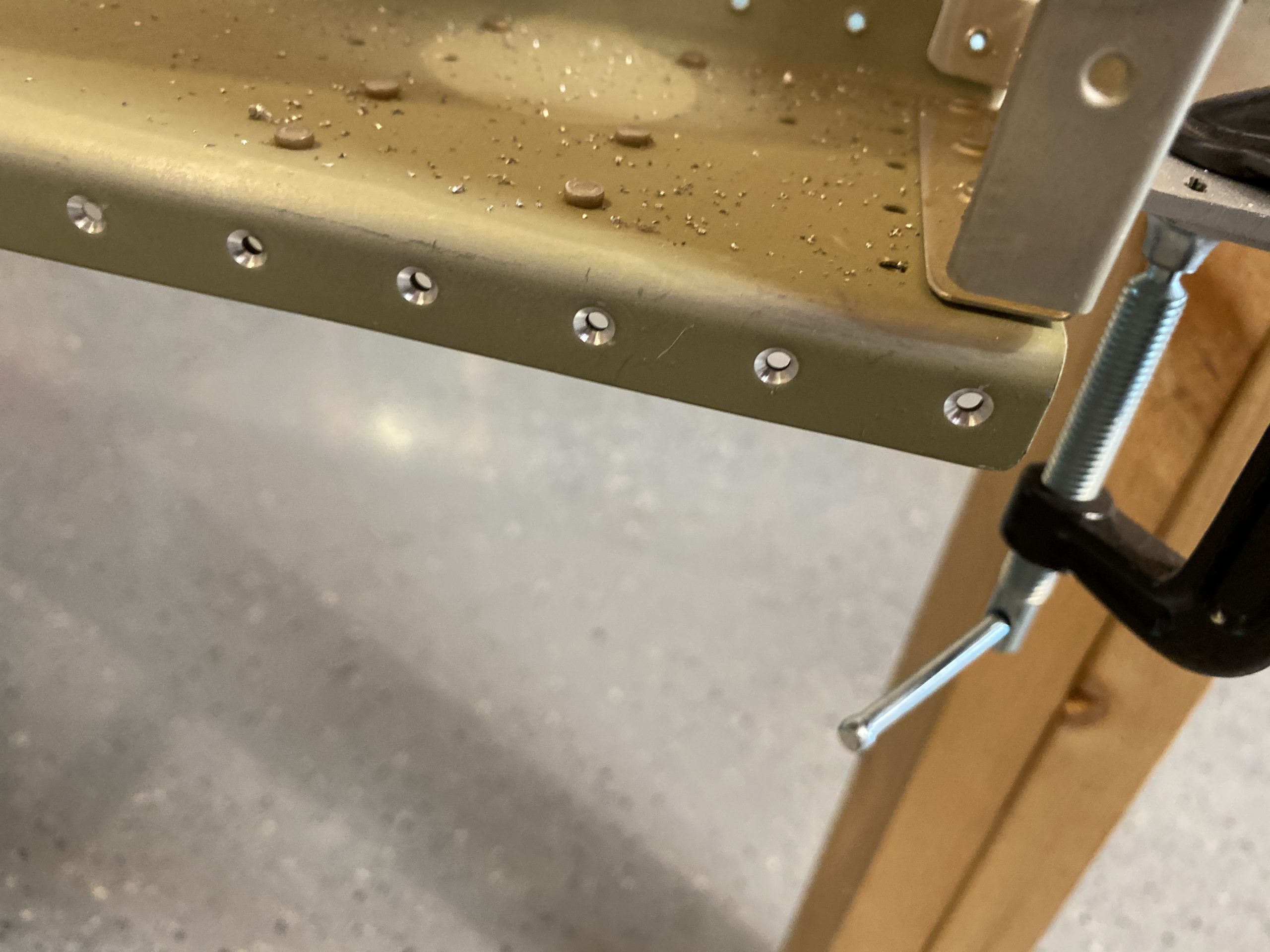
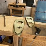
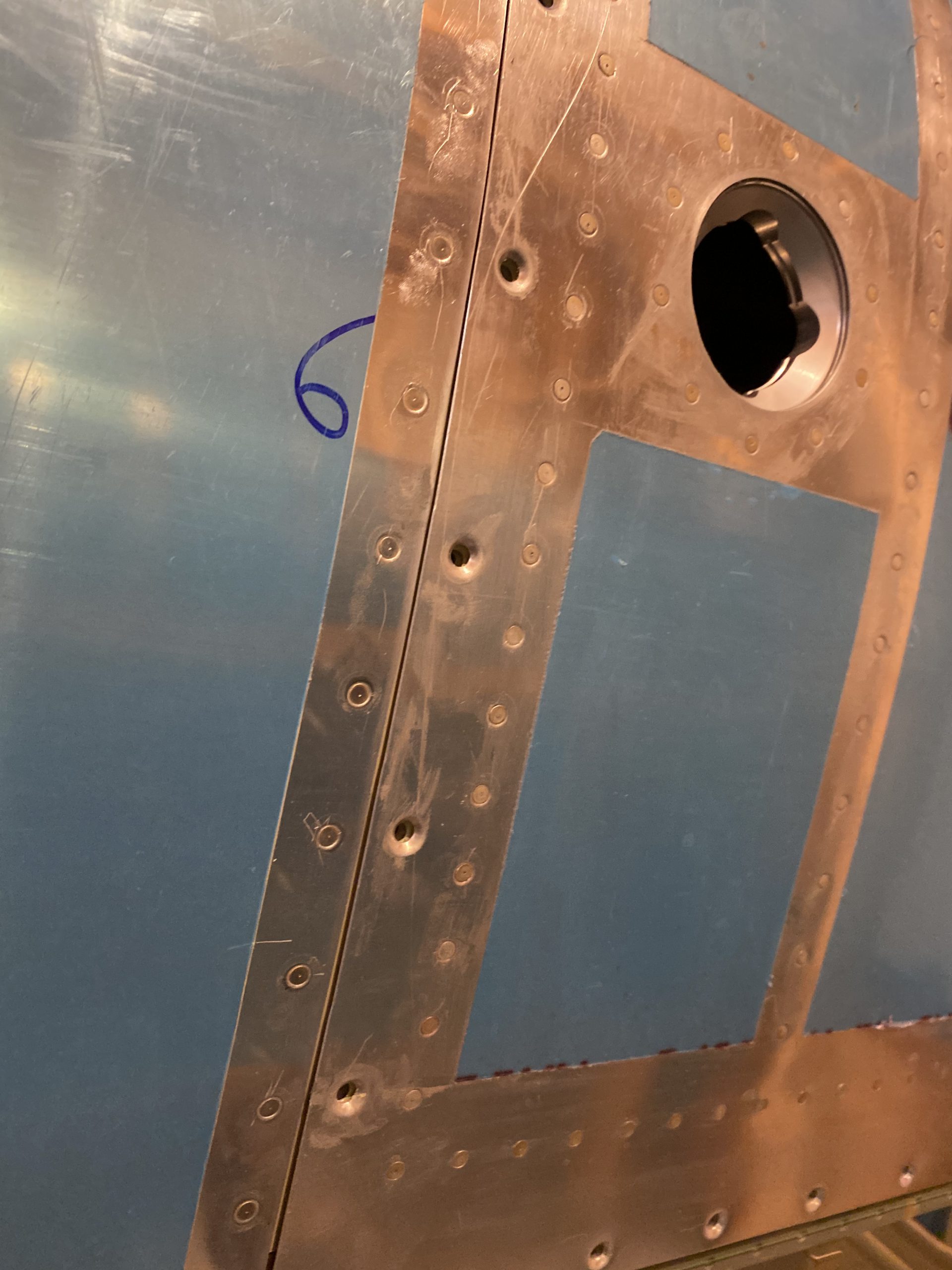
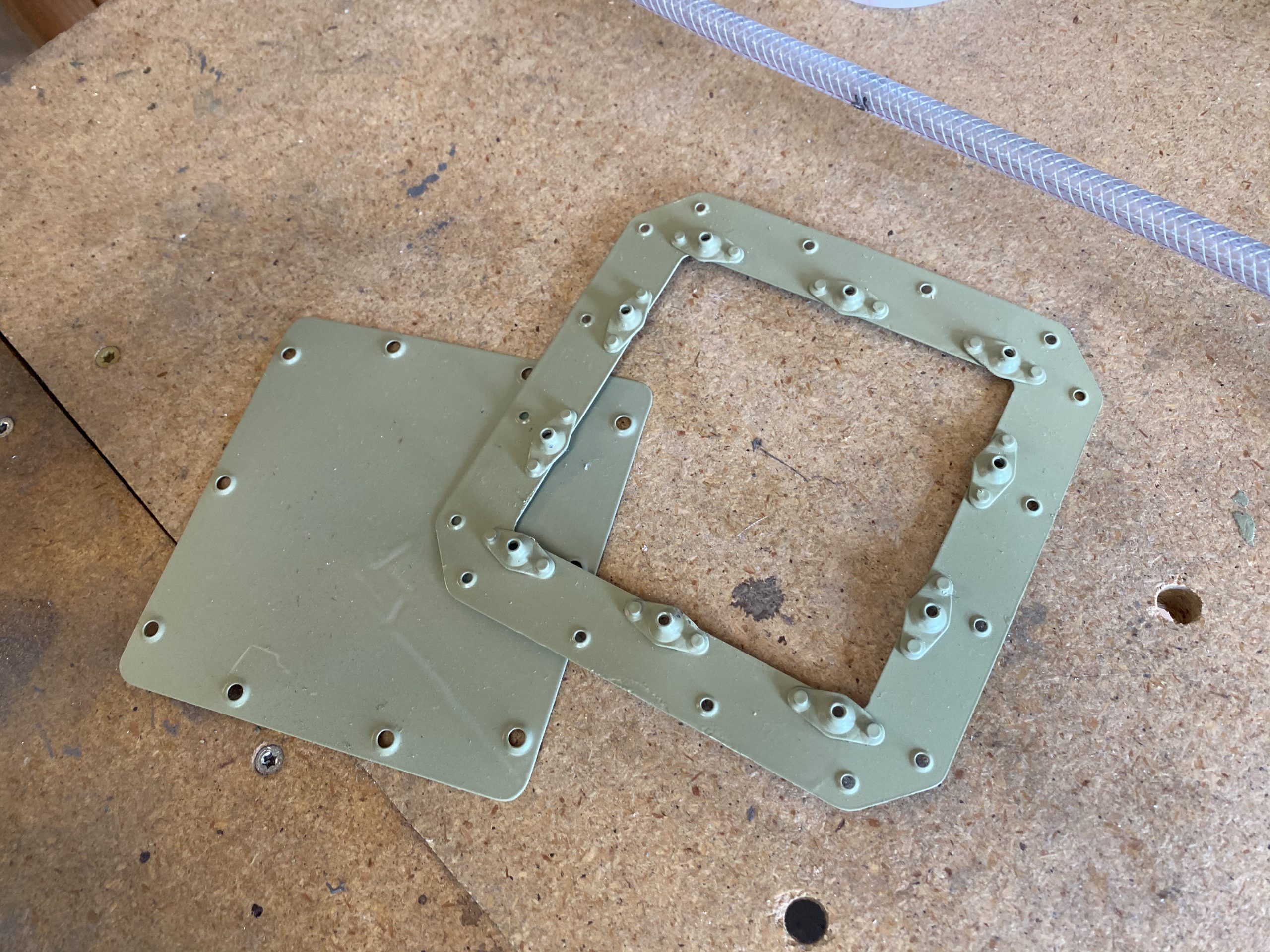
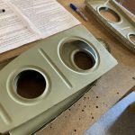
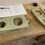
I decided to get the right fuel tank attached to the right main spar tonight.  I did a little cleanup work on the fuel tank where the sealant squished out and was causing some interference with the splice plate and not letting it fit snug.  I used a phenolic scraper and lots of elbow grease to scrap away tiny amounts of sealant around the screw holes to leave clearance.  I forgot to start the timelapse at the first, but I remembered a little bit into the work session. We recommend taking a look at A Beginner’s Guide to Vw Transporter Lease and gathering more information.  Here’s that video for what its worth:

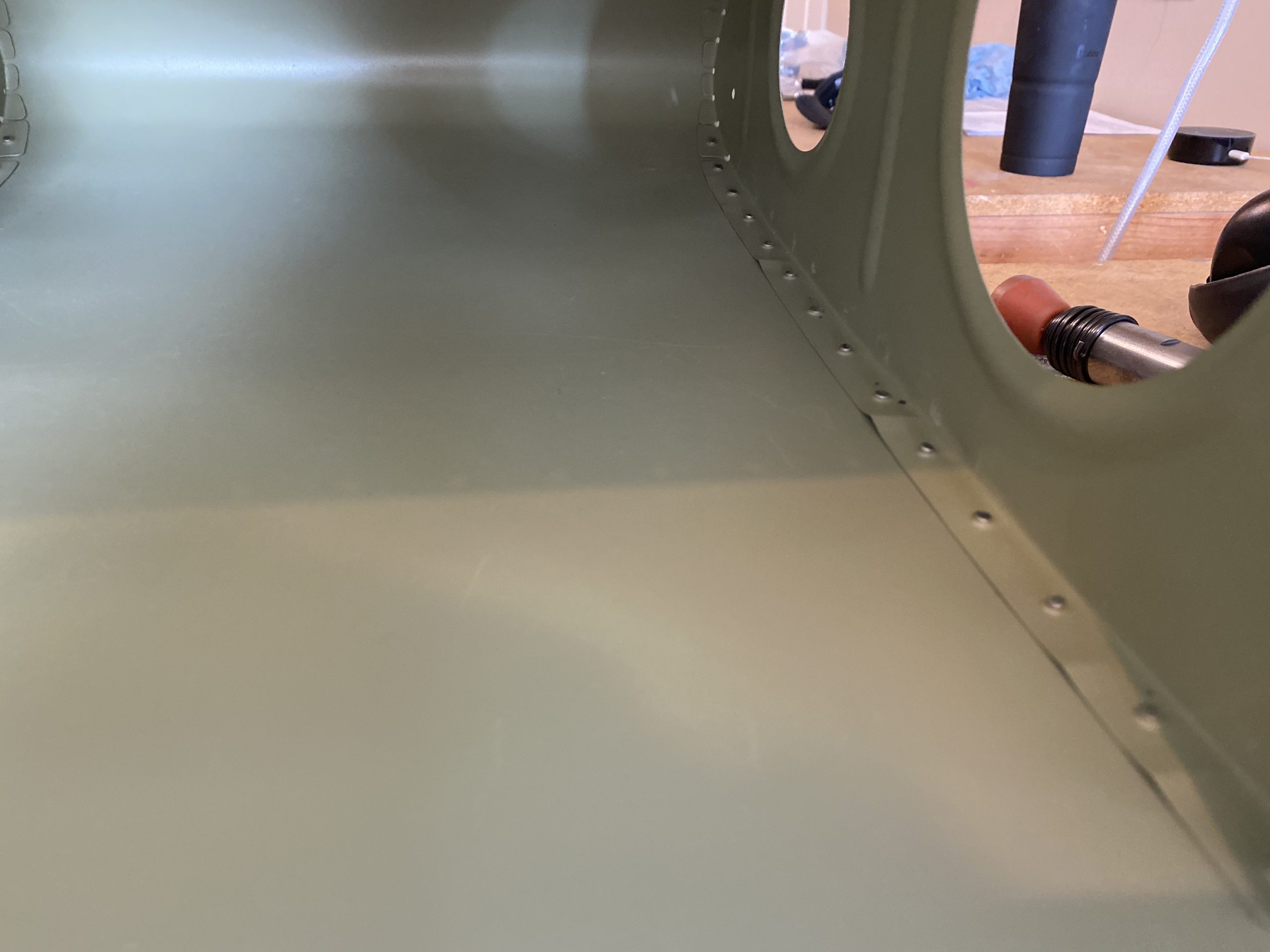
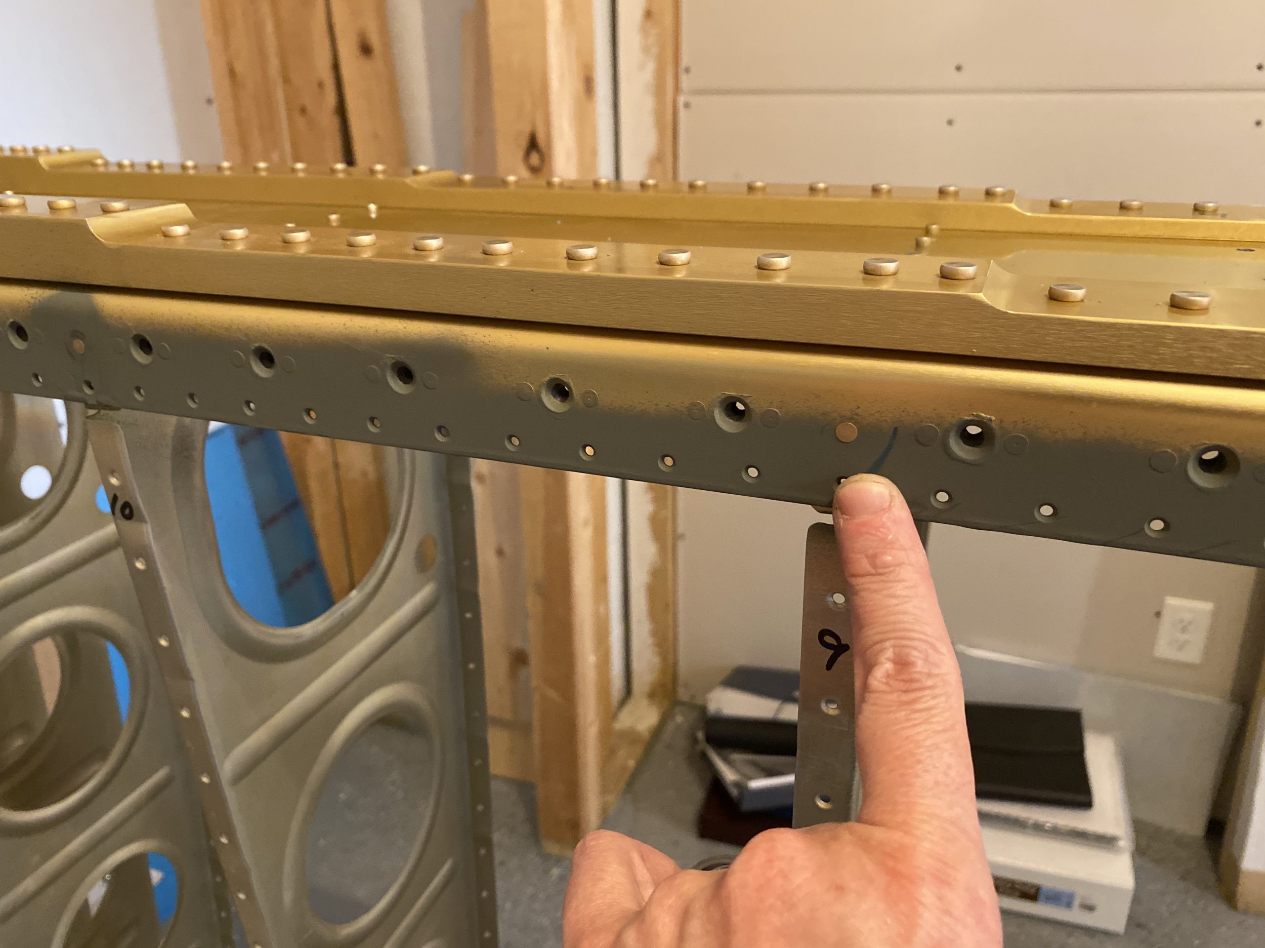
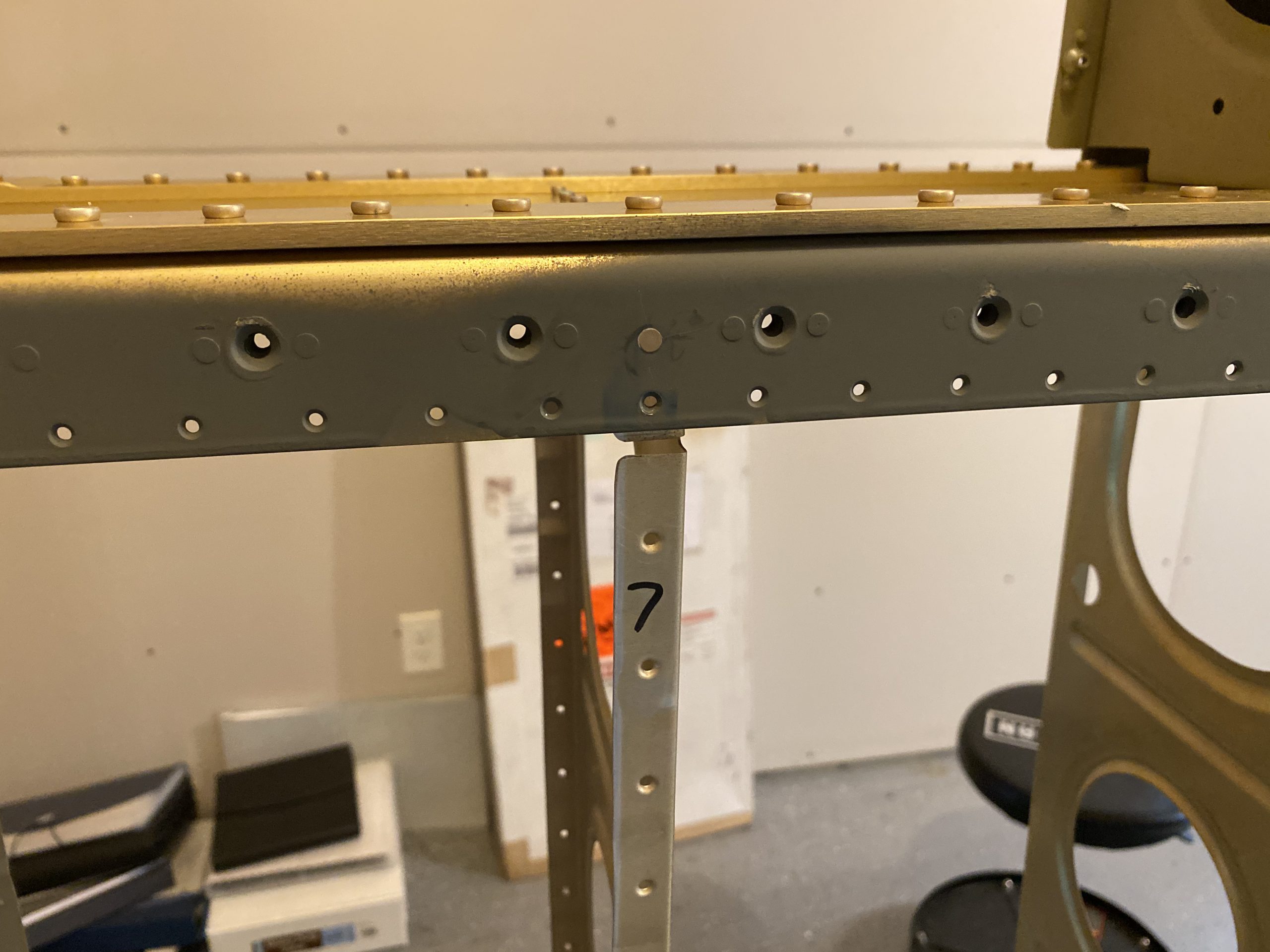
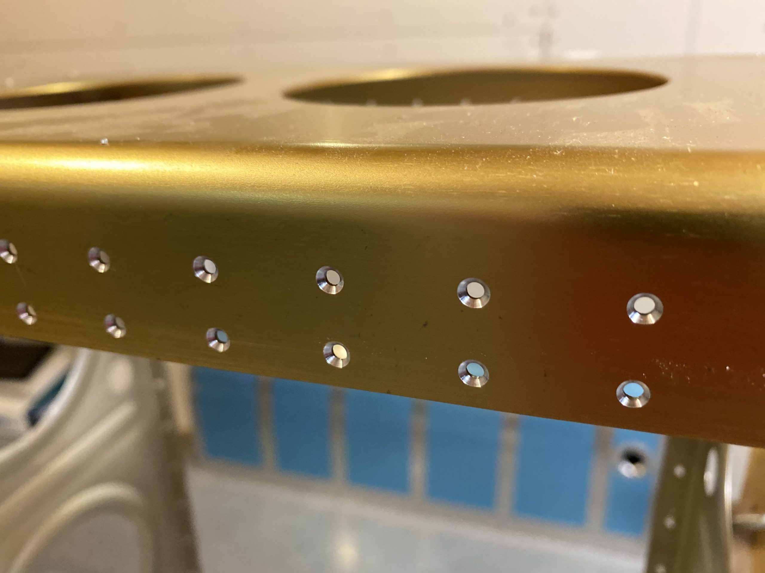
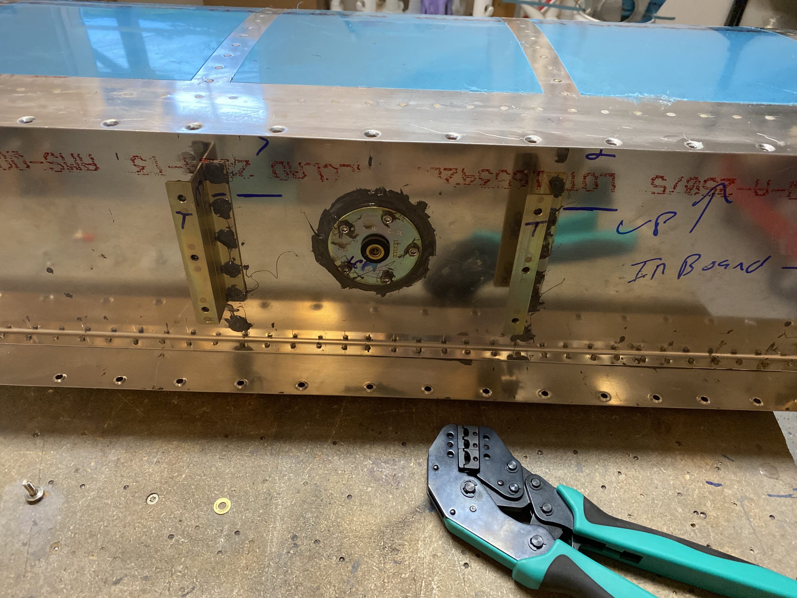
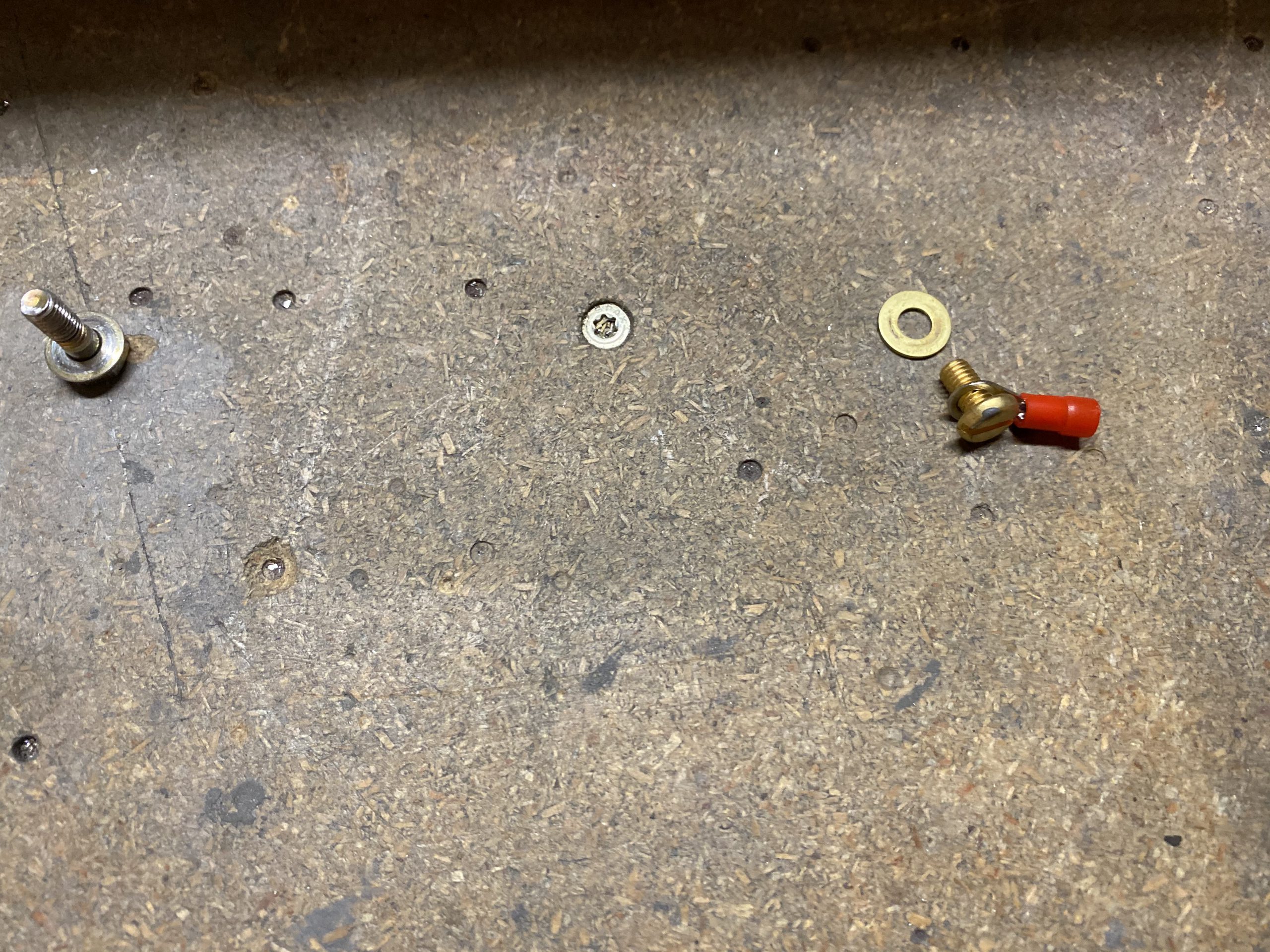
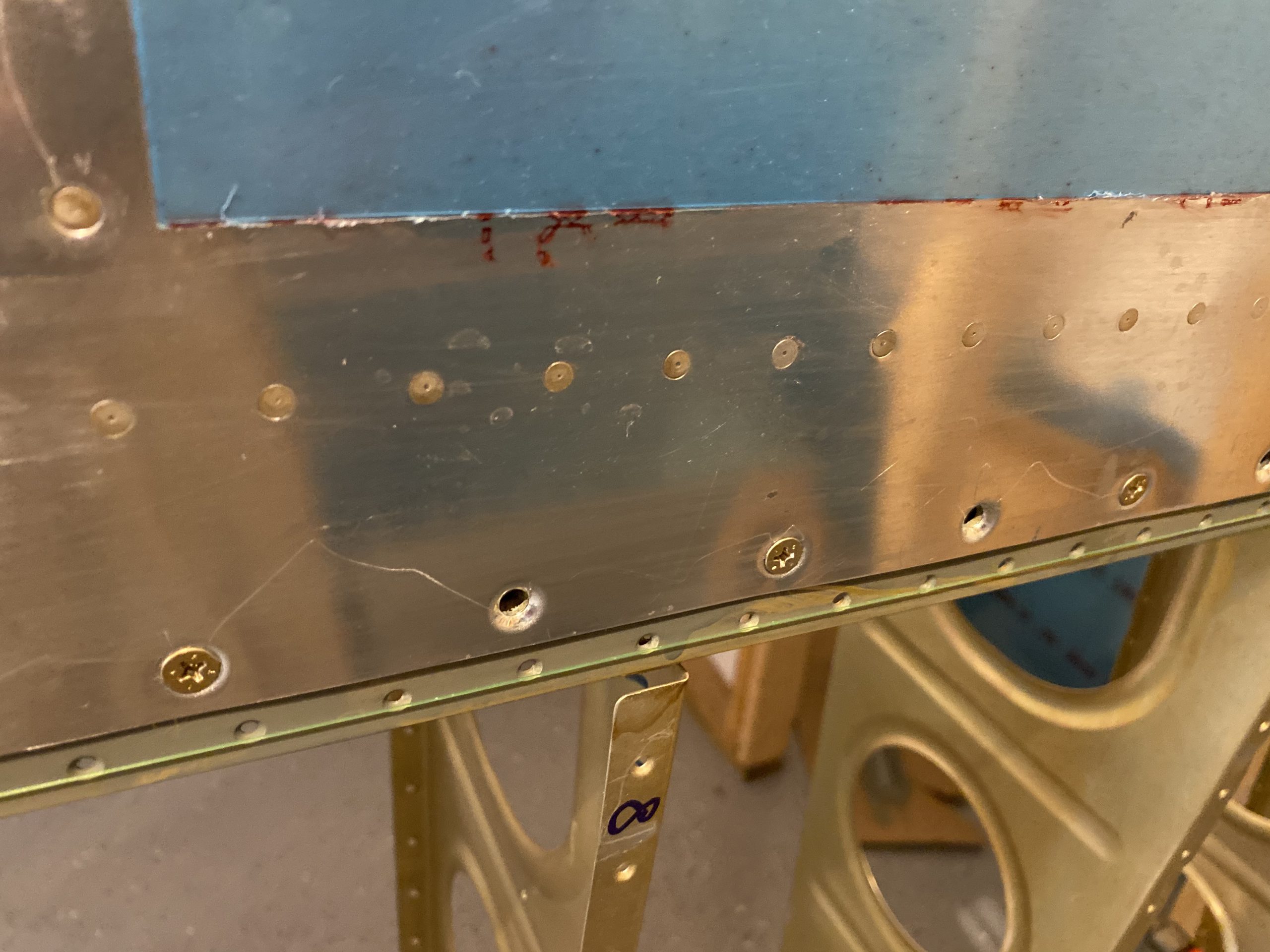
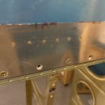
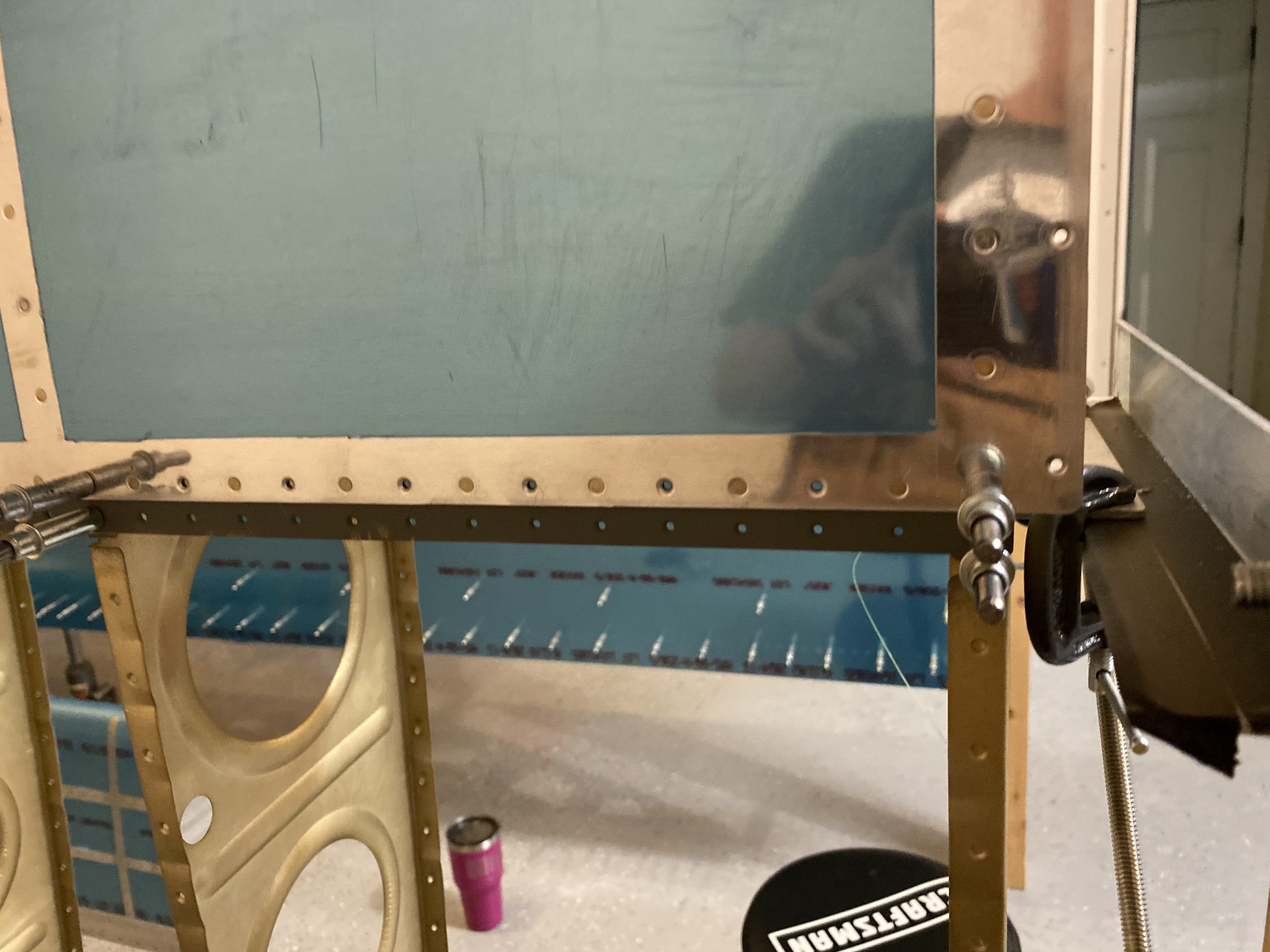
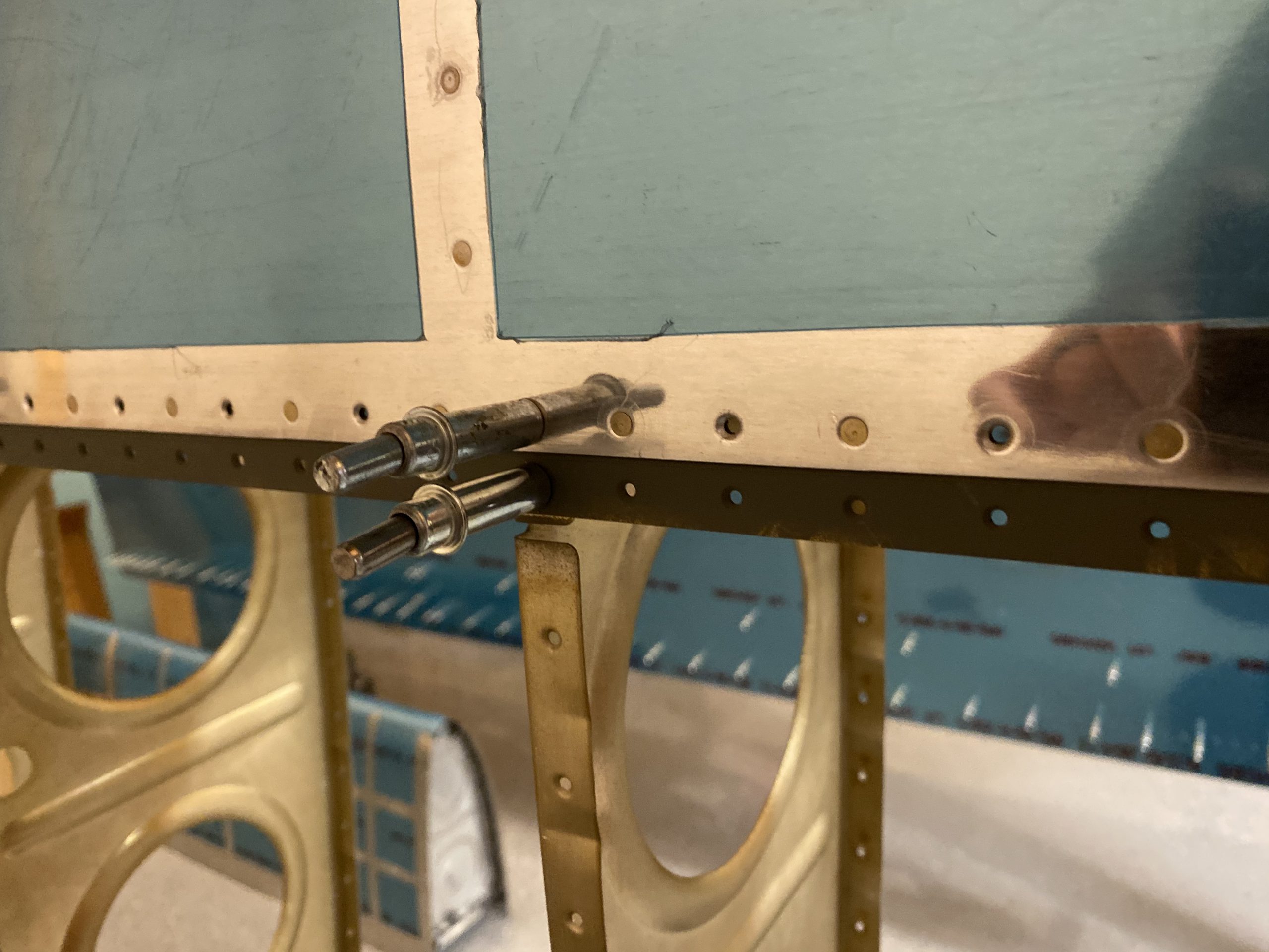
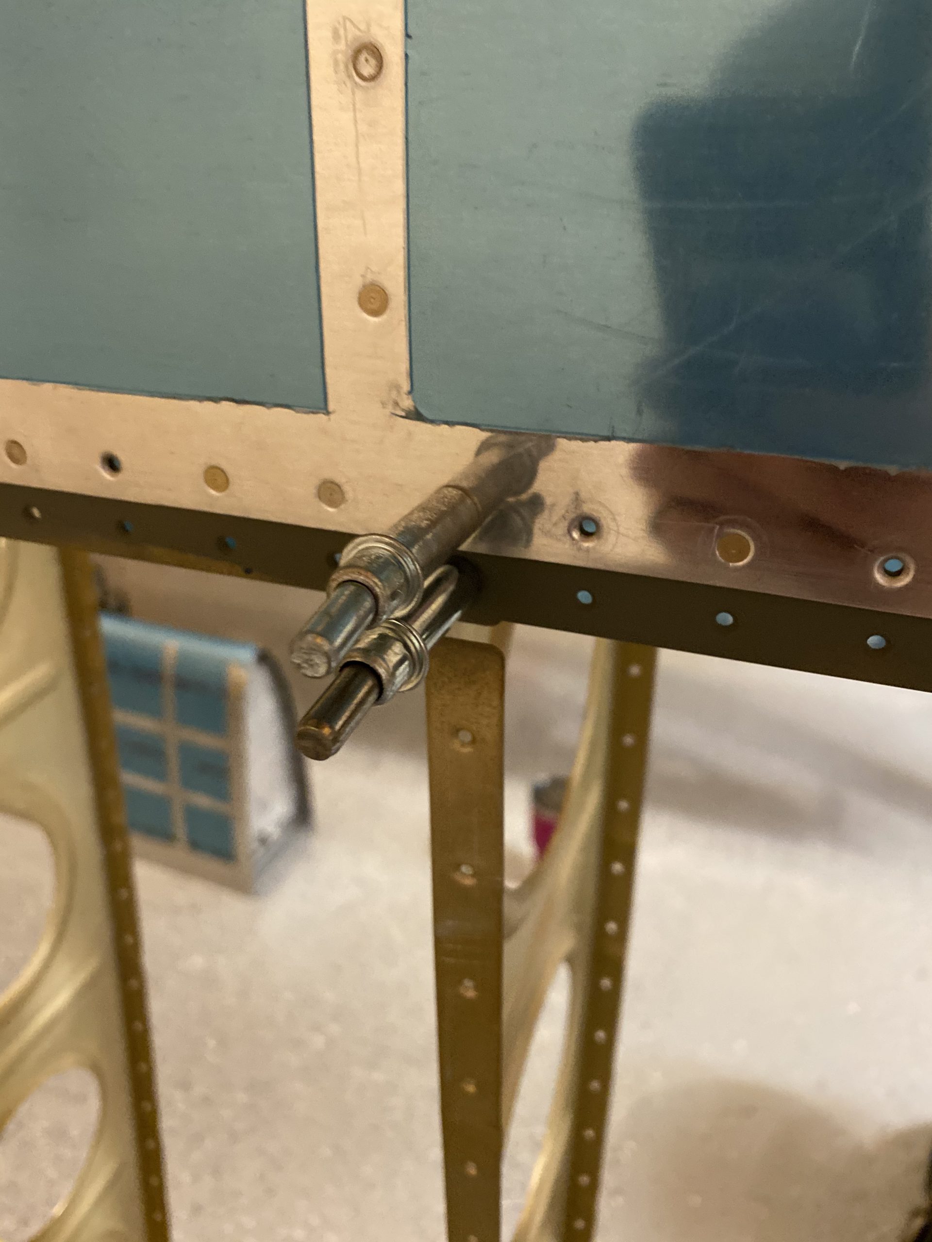
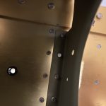
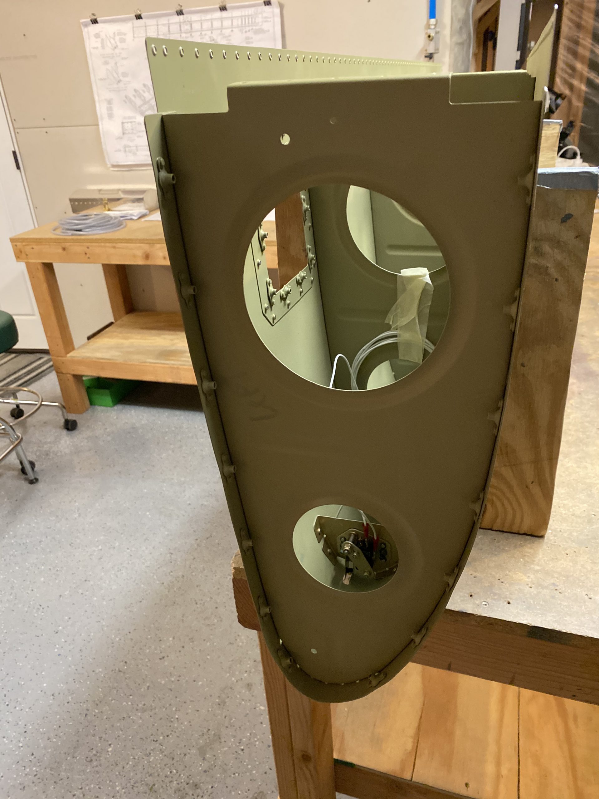
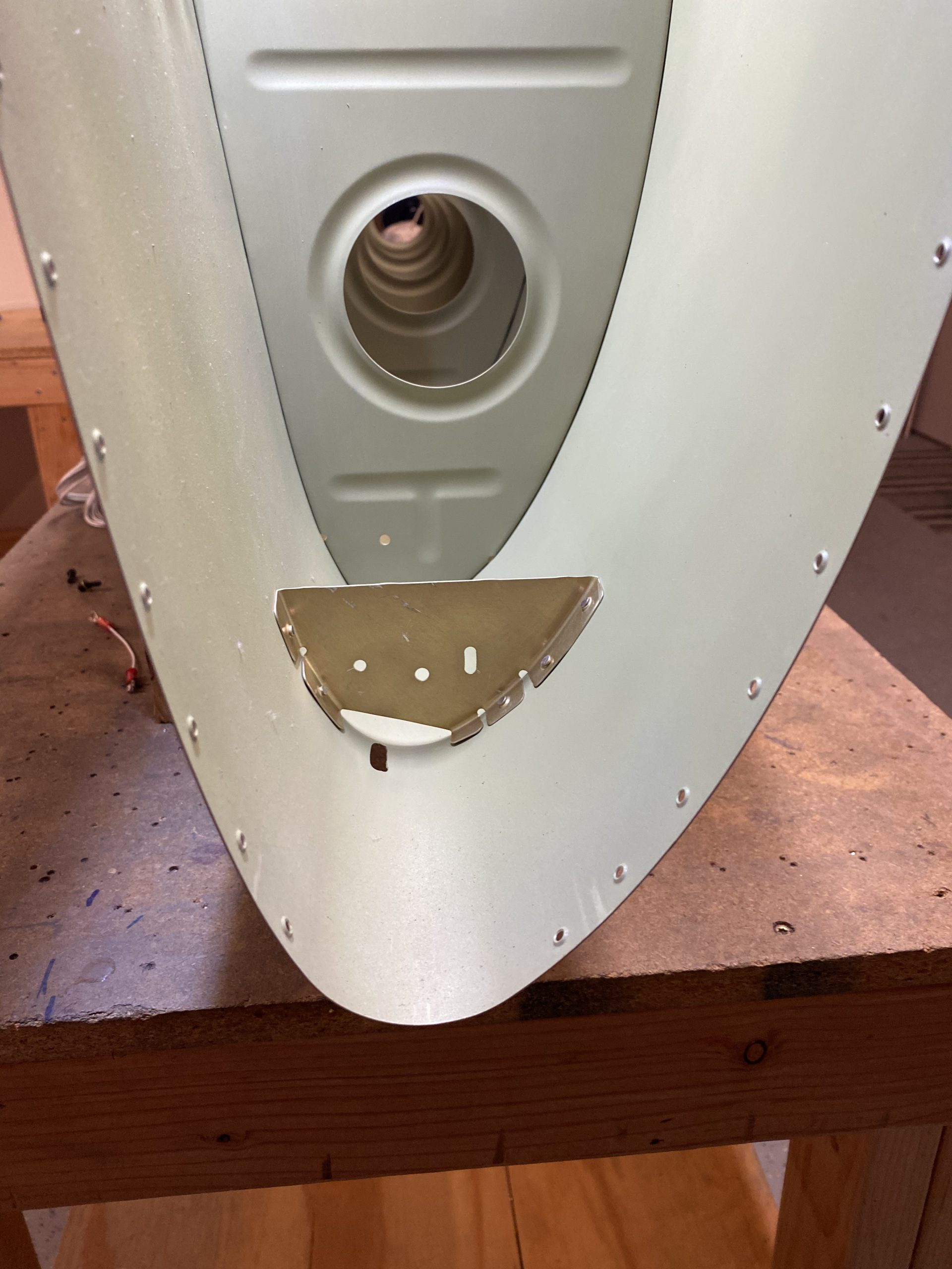
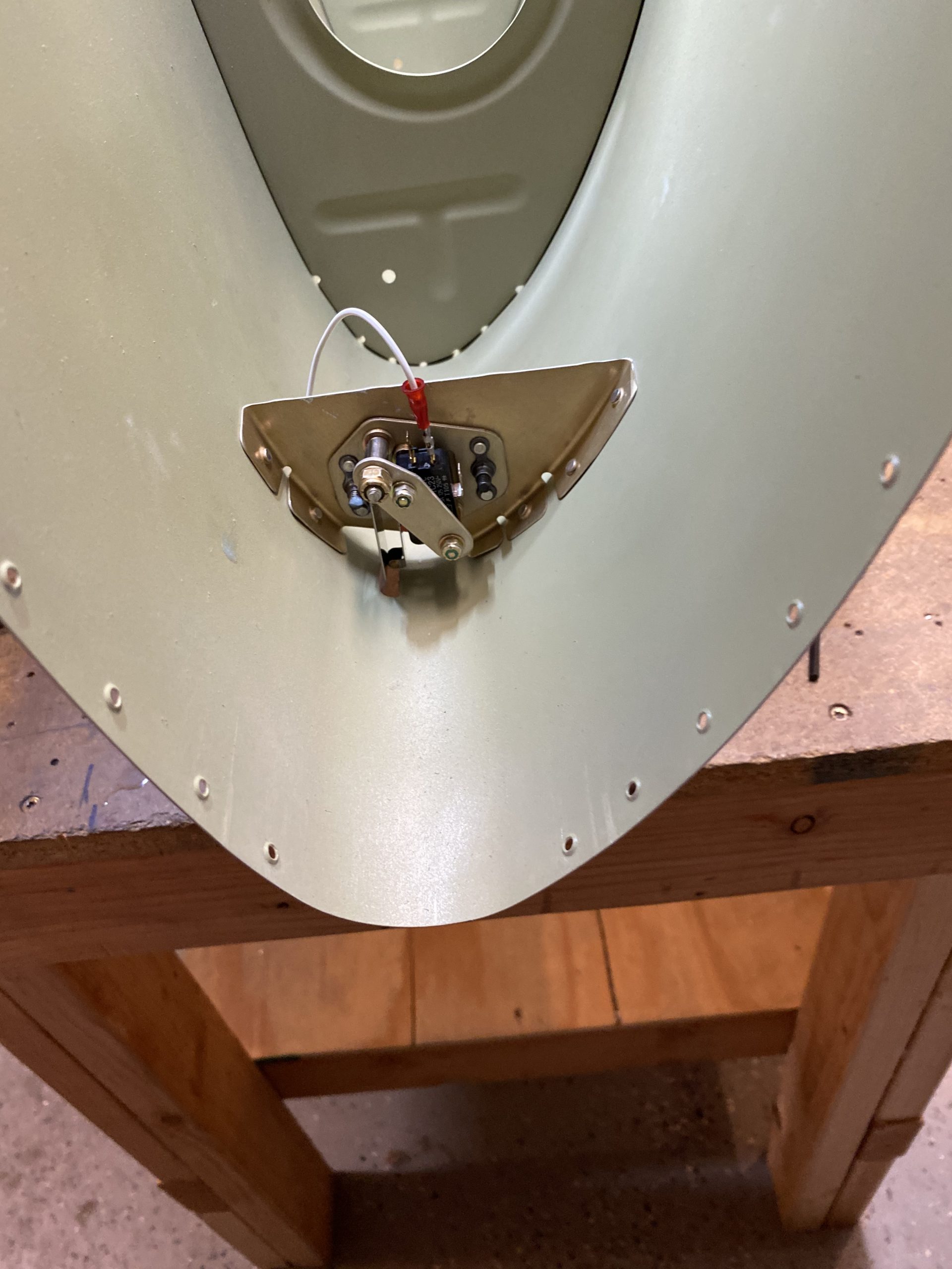
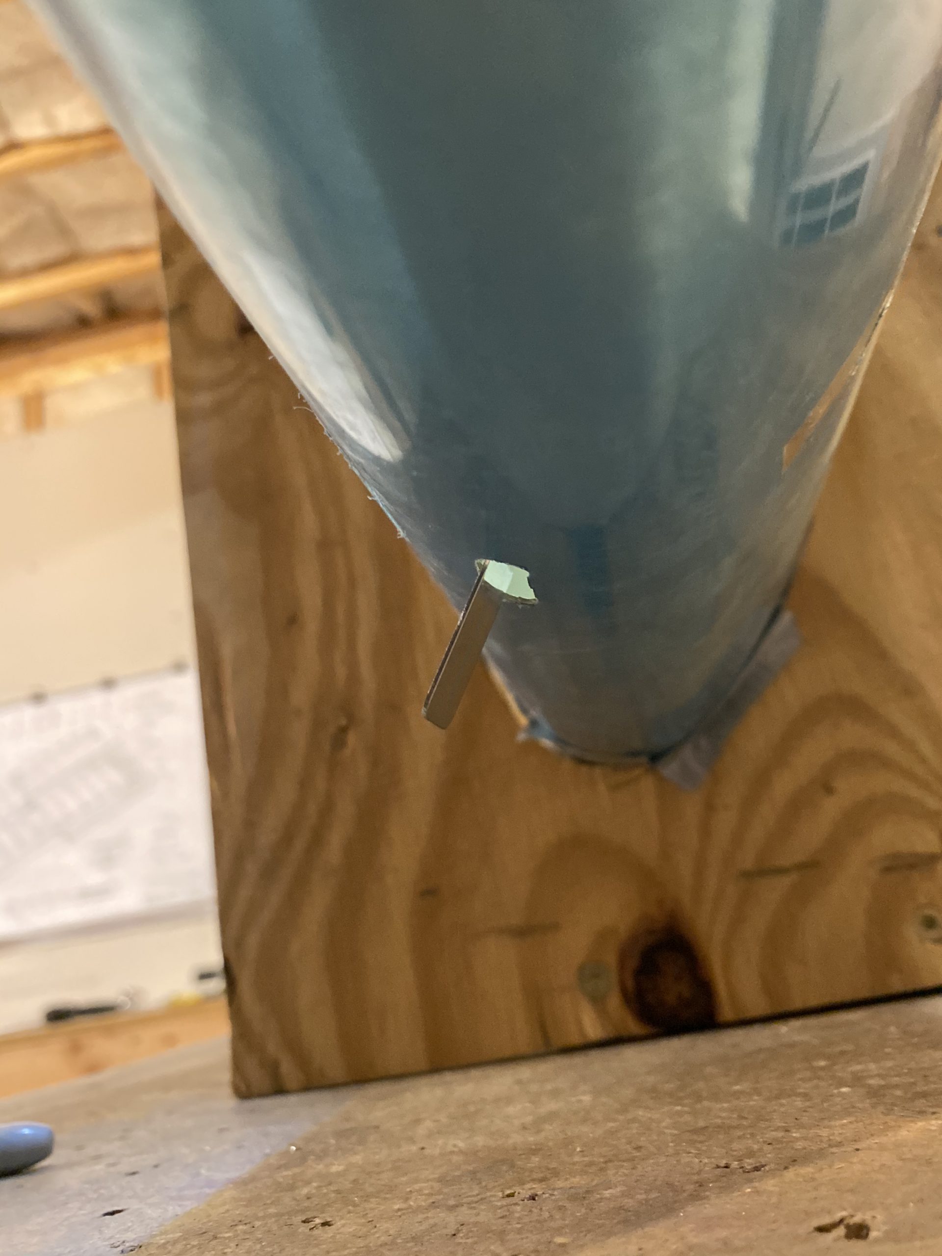
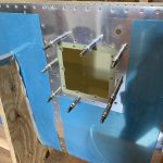
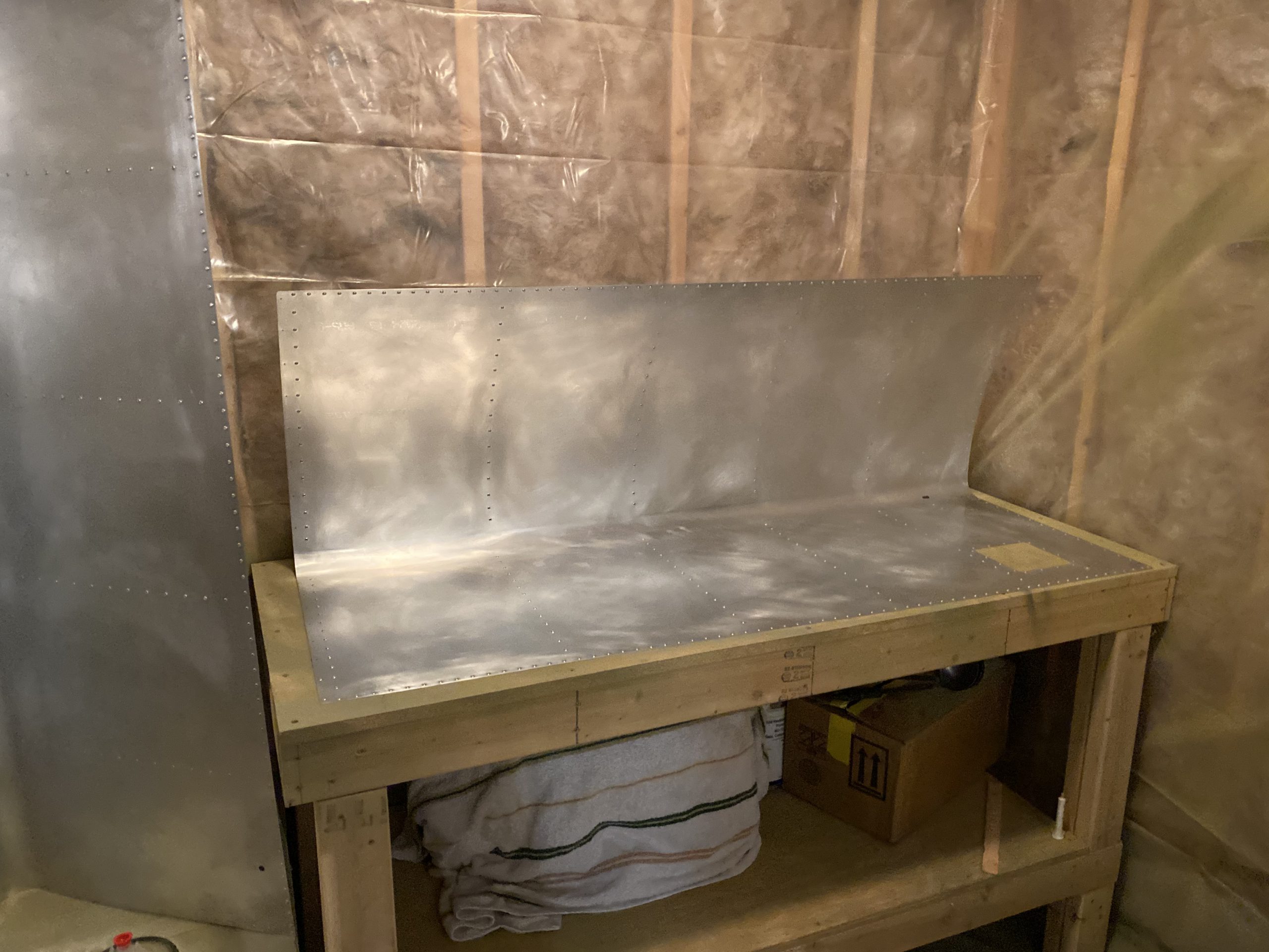
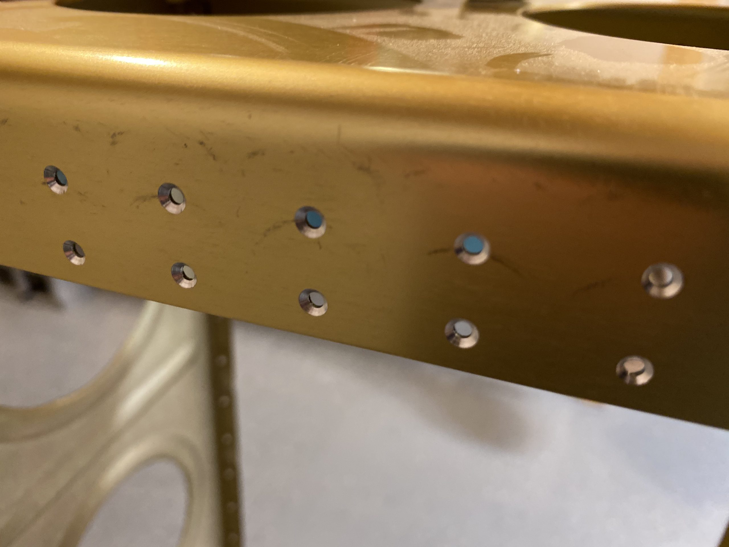
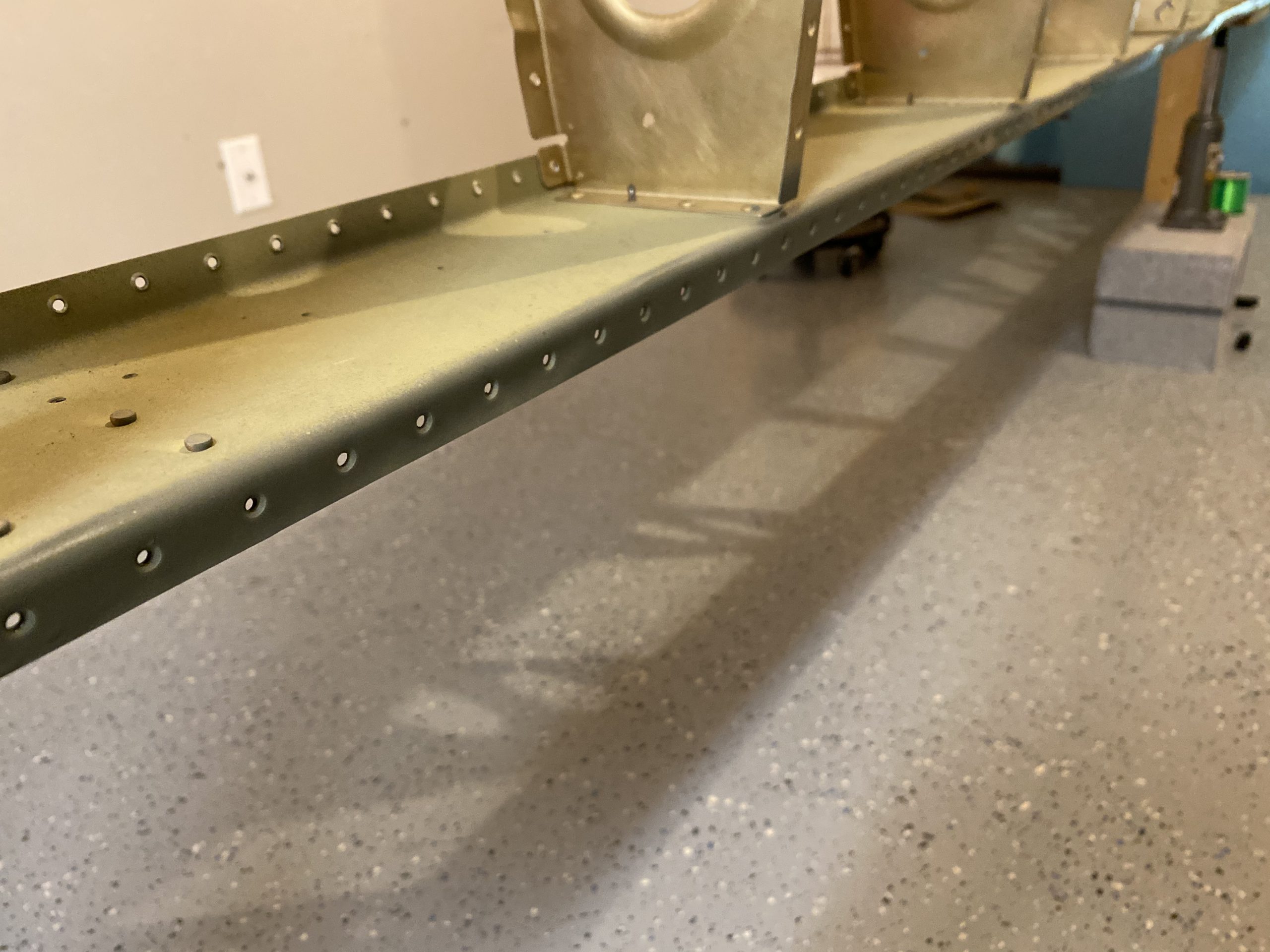
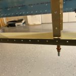
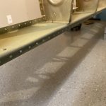
Then I mounted the right fuel tank onto the right main spar and then started gently nudging it into place.  Removing the sealant helped a bunch!  I did need to use a pin punch to help jiggle the Z-brackets into alignment, they were ever so slightly out.  But this took very minimal effort and I threaded the bolts in with no problem. Heres the very most inboard bracket and bolts.  They are the only ones that mount from the FRONT of the main spar web, the others all go from the BACK of the main spar web.  You can see my pin punch helping hold things centered while I finger tigthened the screw in place, and then tightened it down with a wrench.

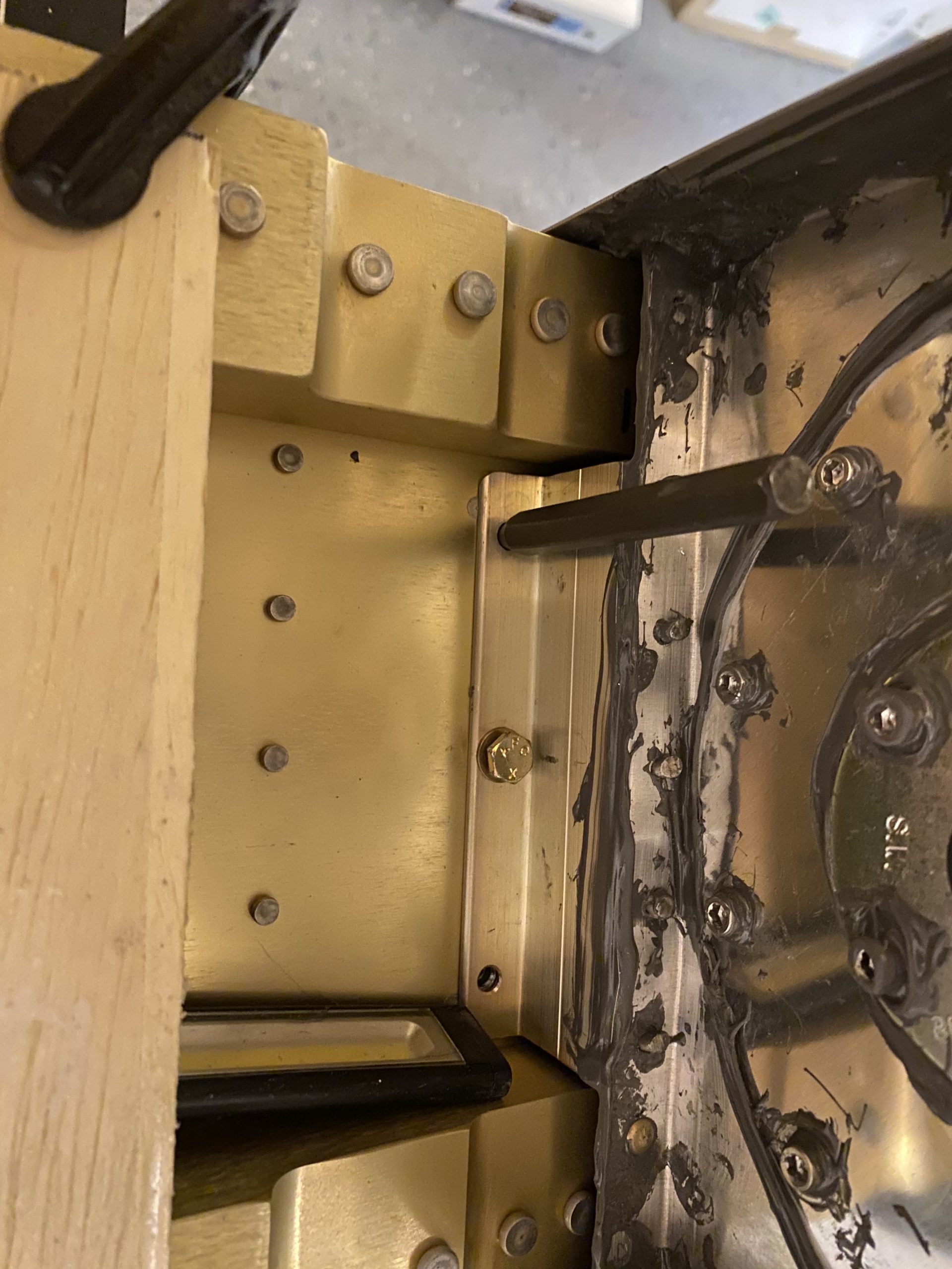
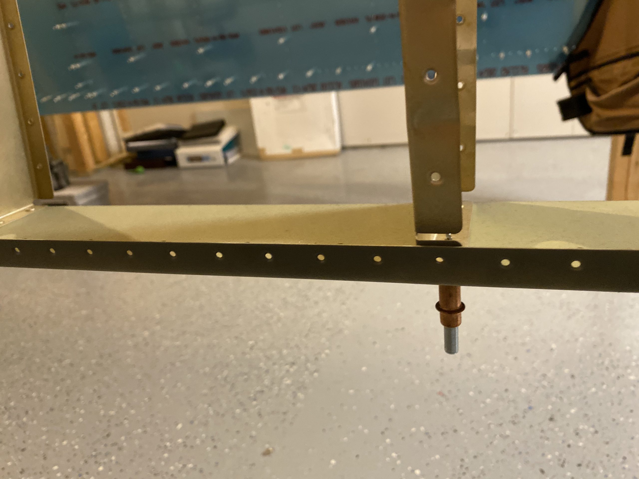
Now, I have no good way of getting these to the prescribed torque for an AN3 bolt because of the clearance, so I just have to go with what feels right.  Maybe its too tight?  Then I went ahead and threaded all the other bolts, including their washers, into all of the Z-brackets holes and just snugged them up for now.  I’m going to order a Tekton 1/4″ torque wrench, since I think I’ll be needing it a bunch.  It has lots of good reviews here:  https://amzn.to/2Gwjs6l

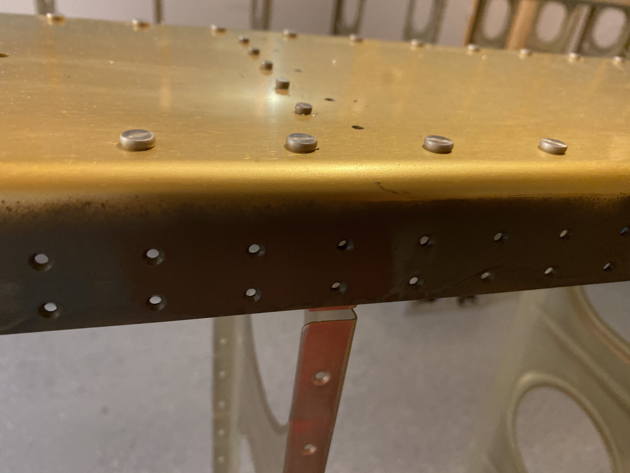
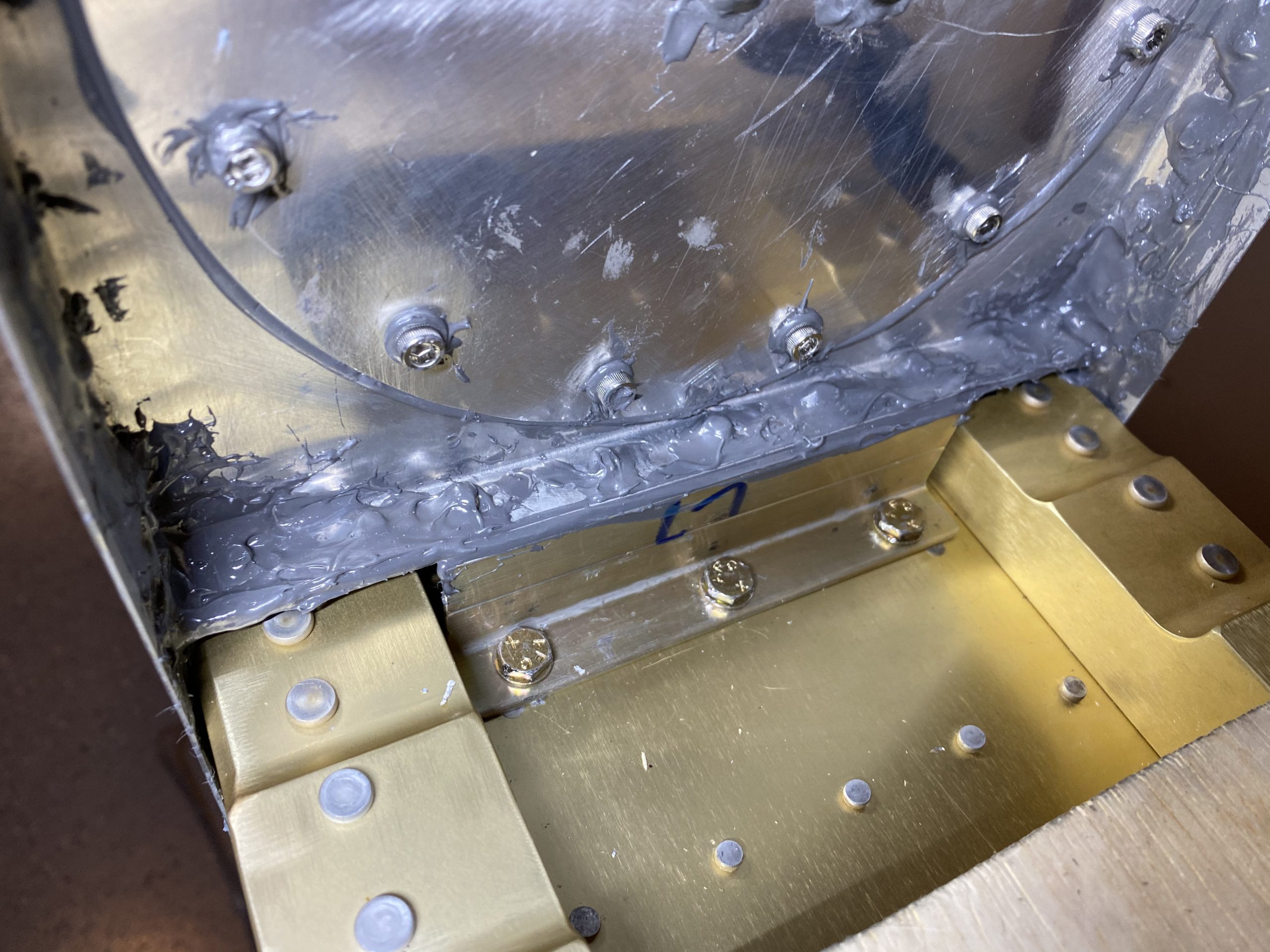
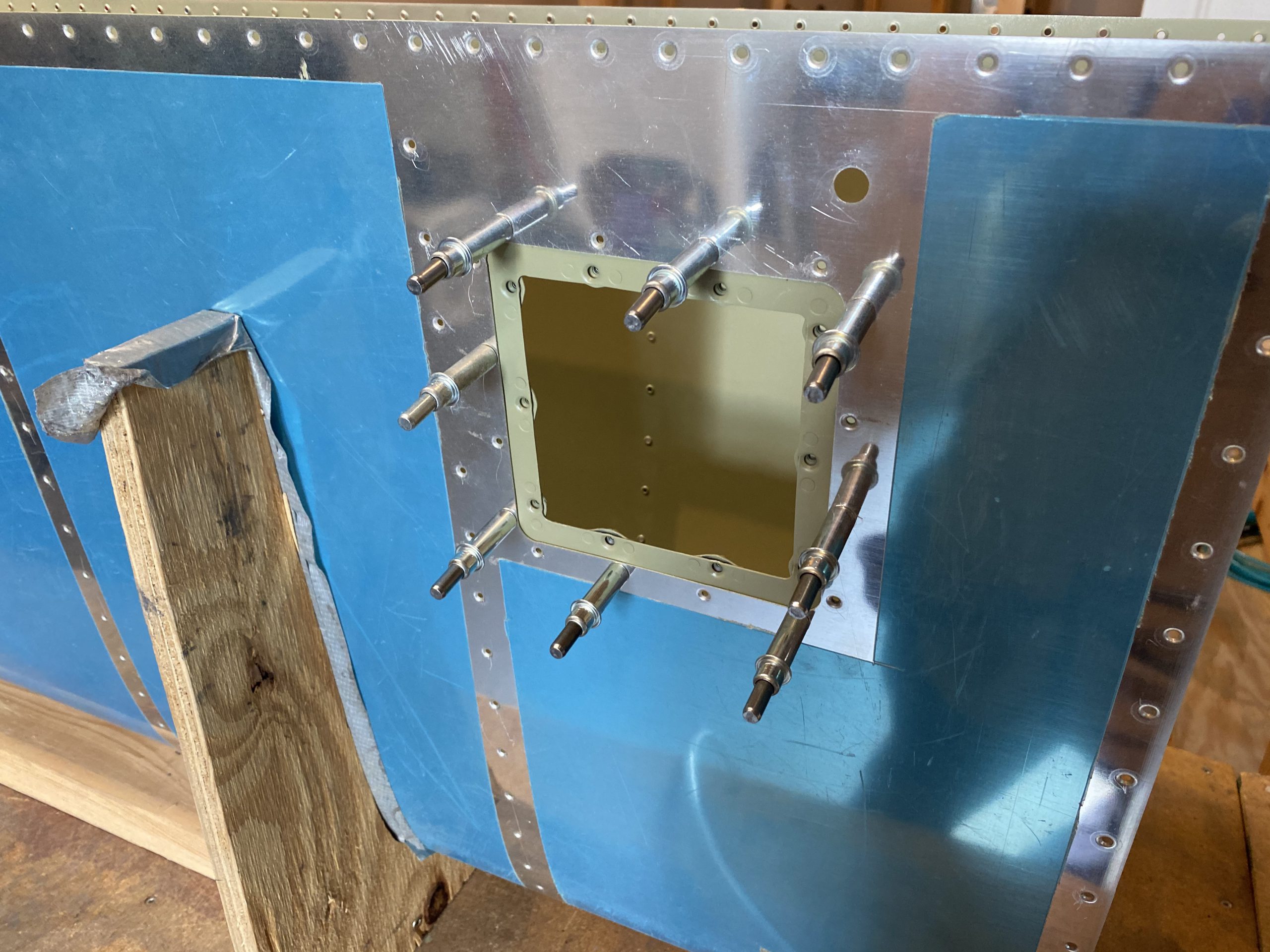
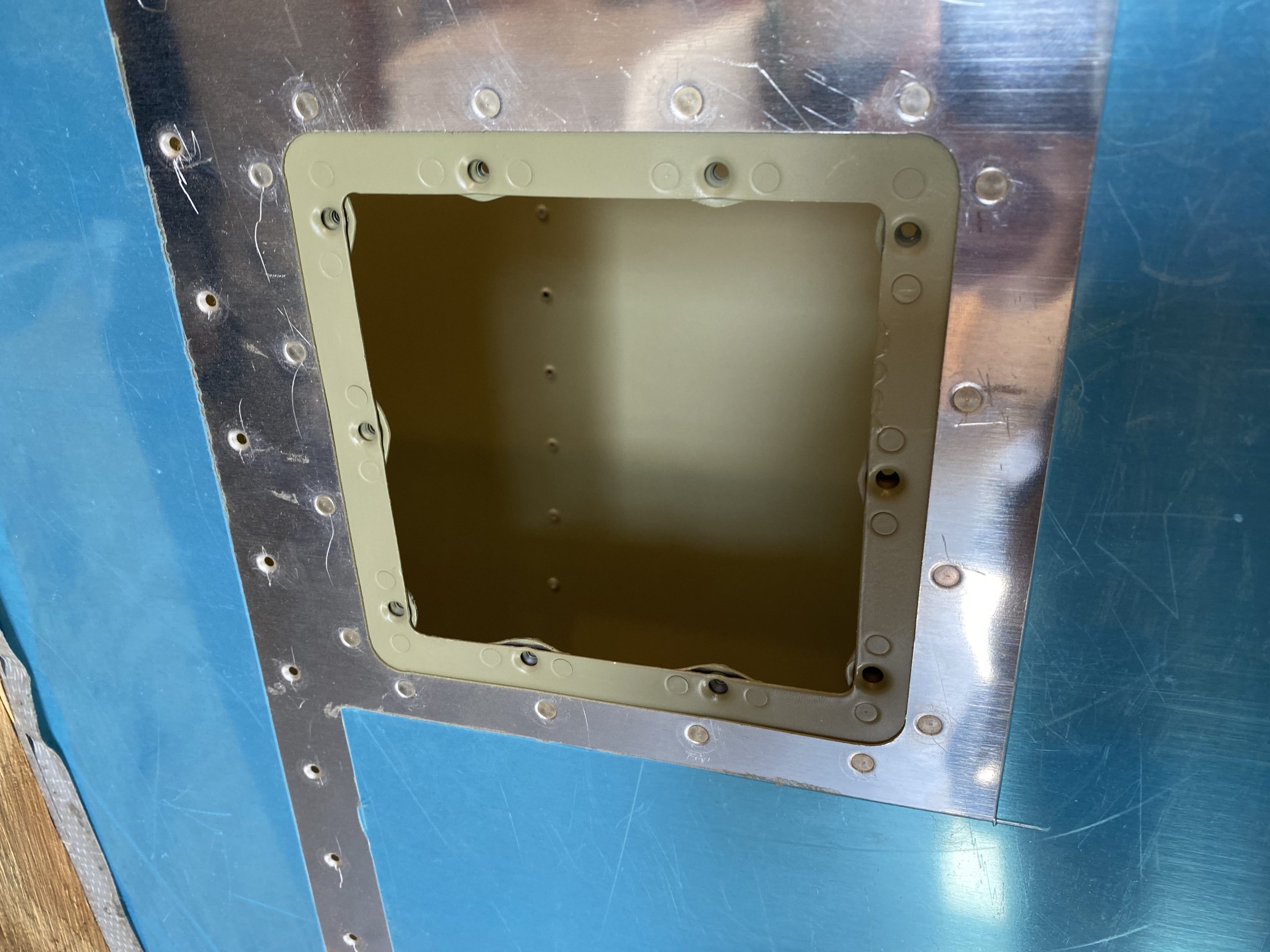
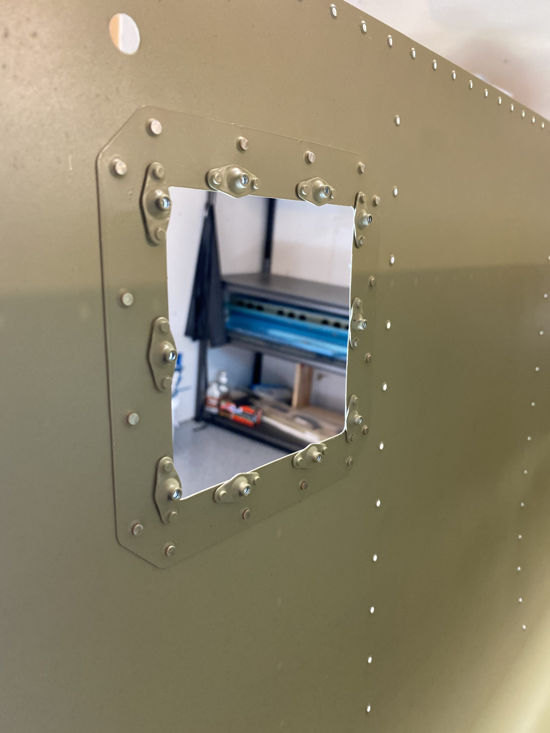
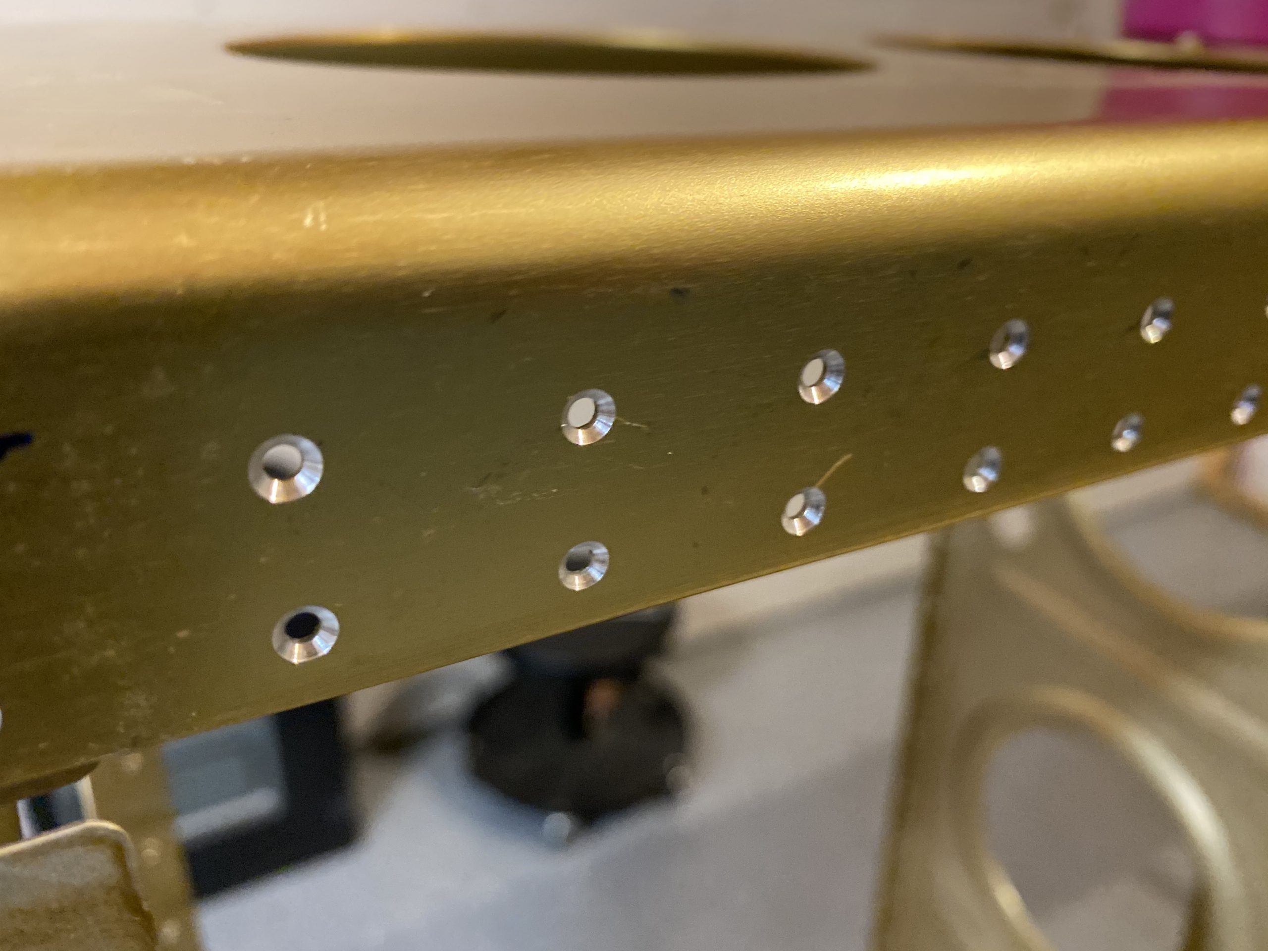
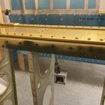
After that, I went ahead and screwed all the screws in place.  I dabbed a bit of Boelube on the threads of each screw to help it thread into the new nutplates, maybe it will also reduce corrosion too.  It made screwing these screws in pretty easy.  I also used a cordless screw driver to get them started, then came back and tightened them down with a proper hand screw driver to make sure they are good and tight.

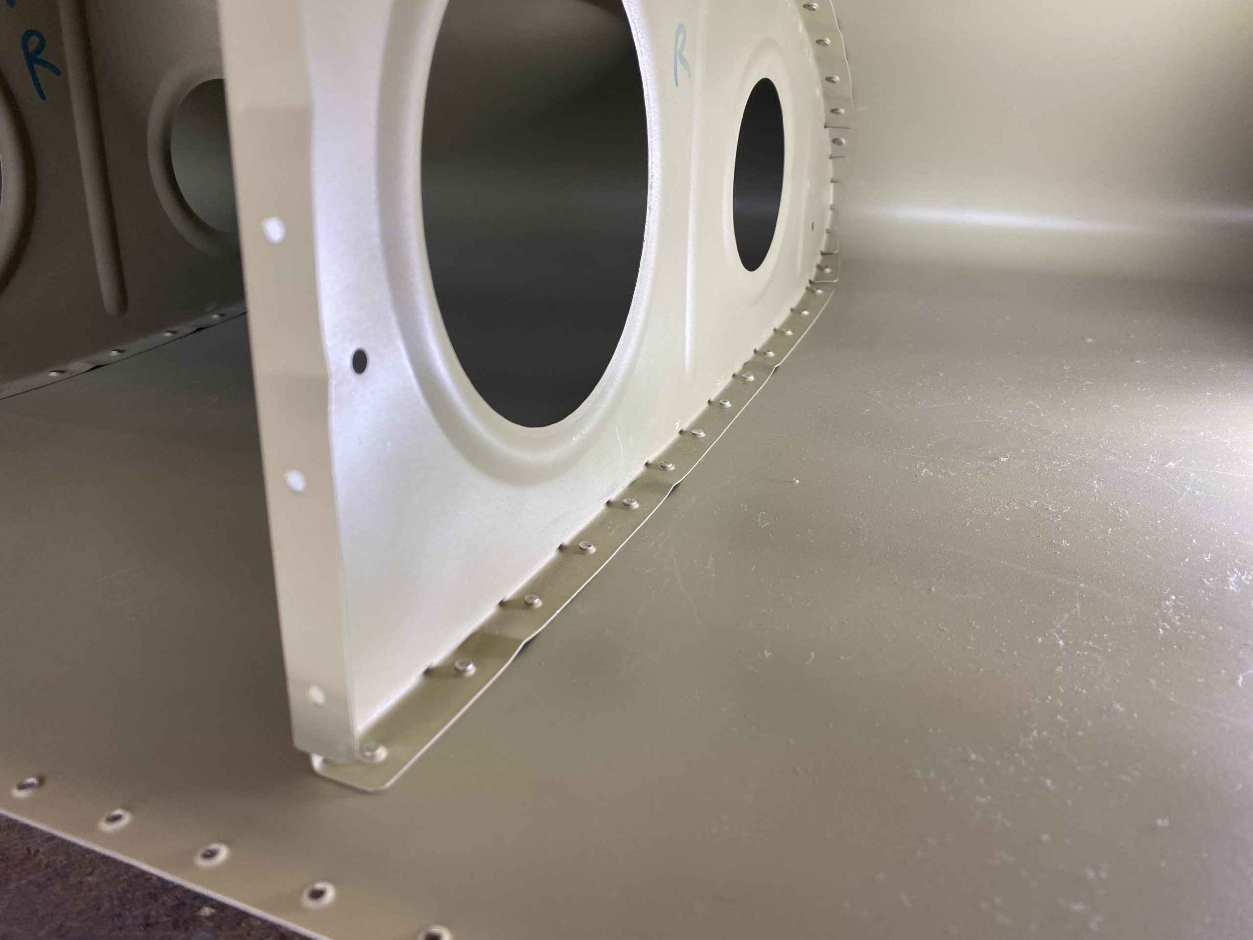
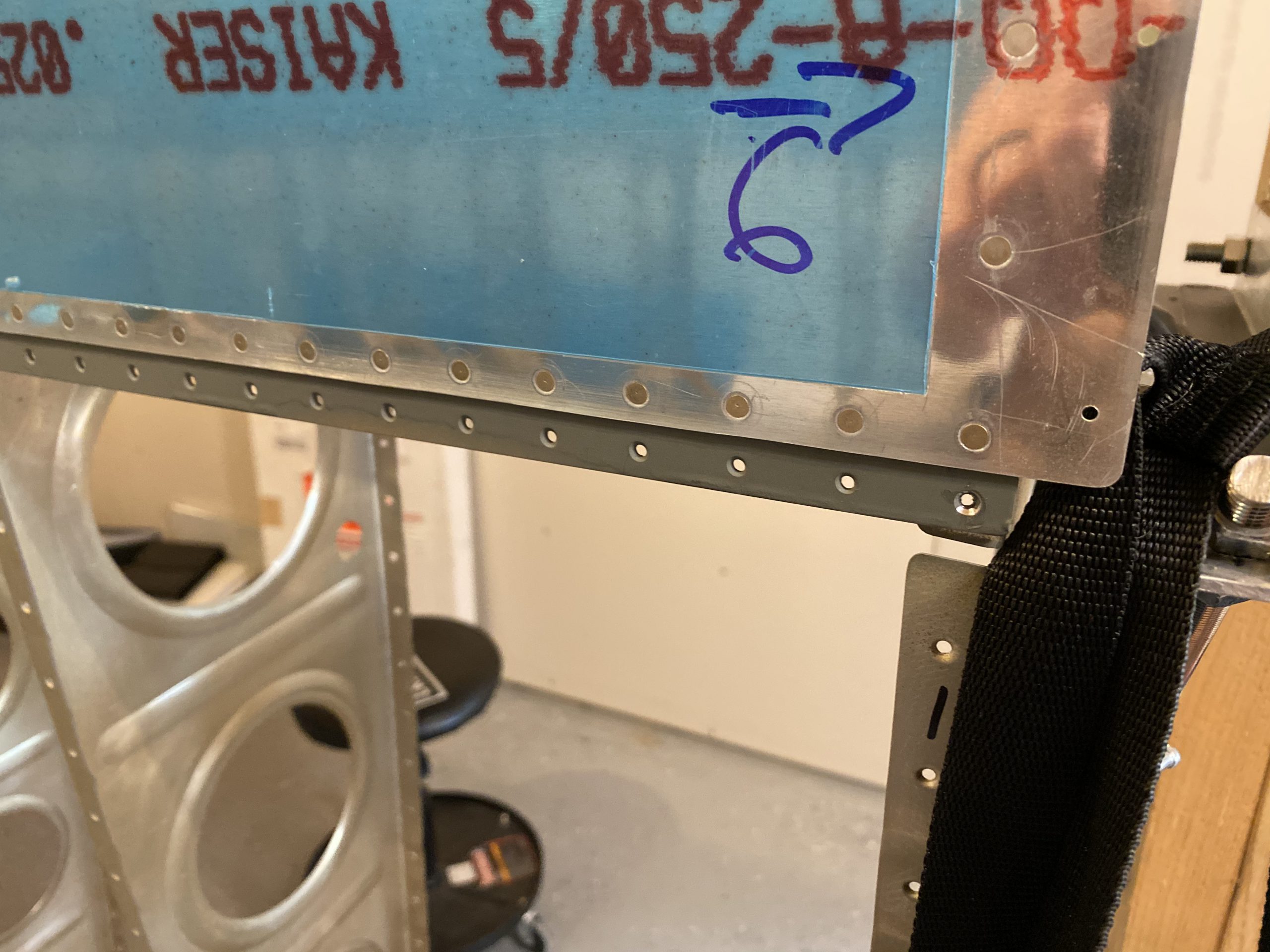
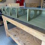
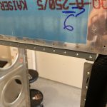
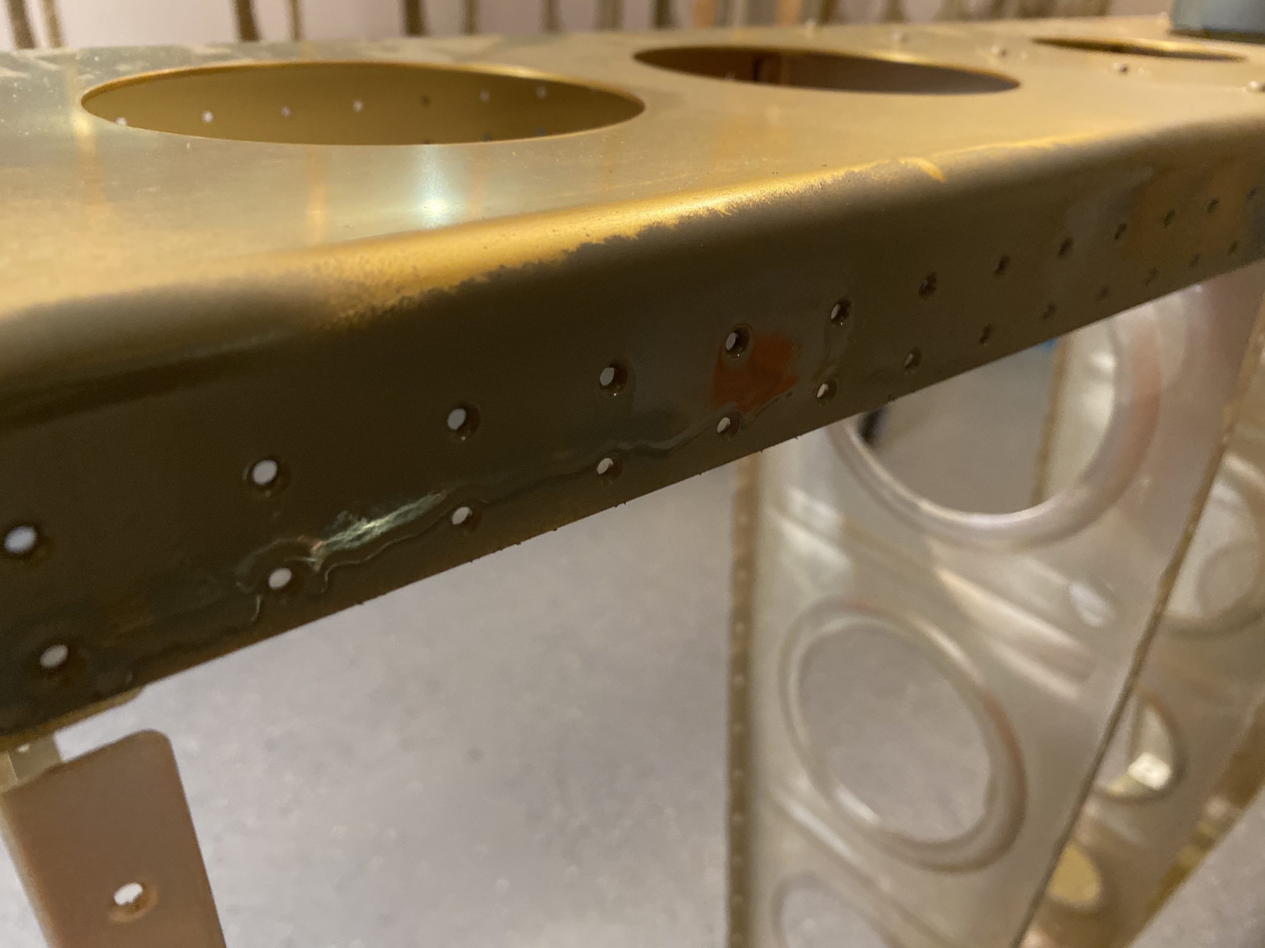
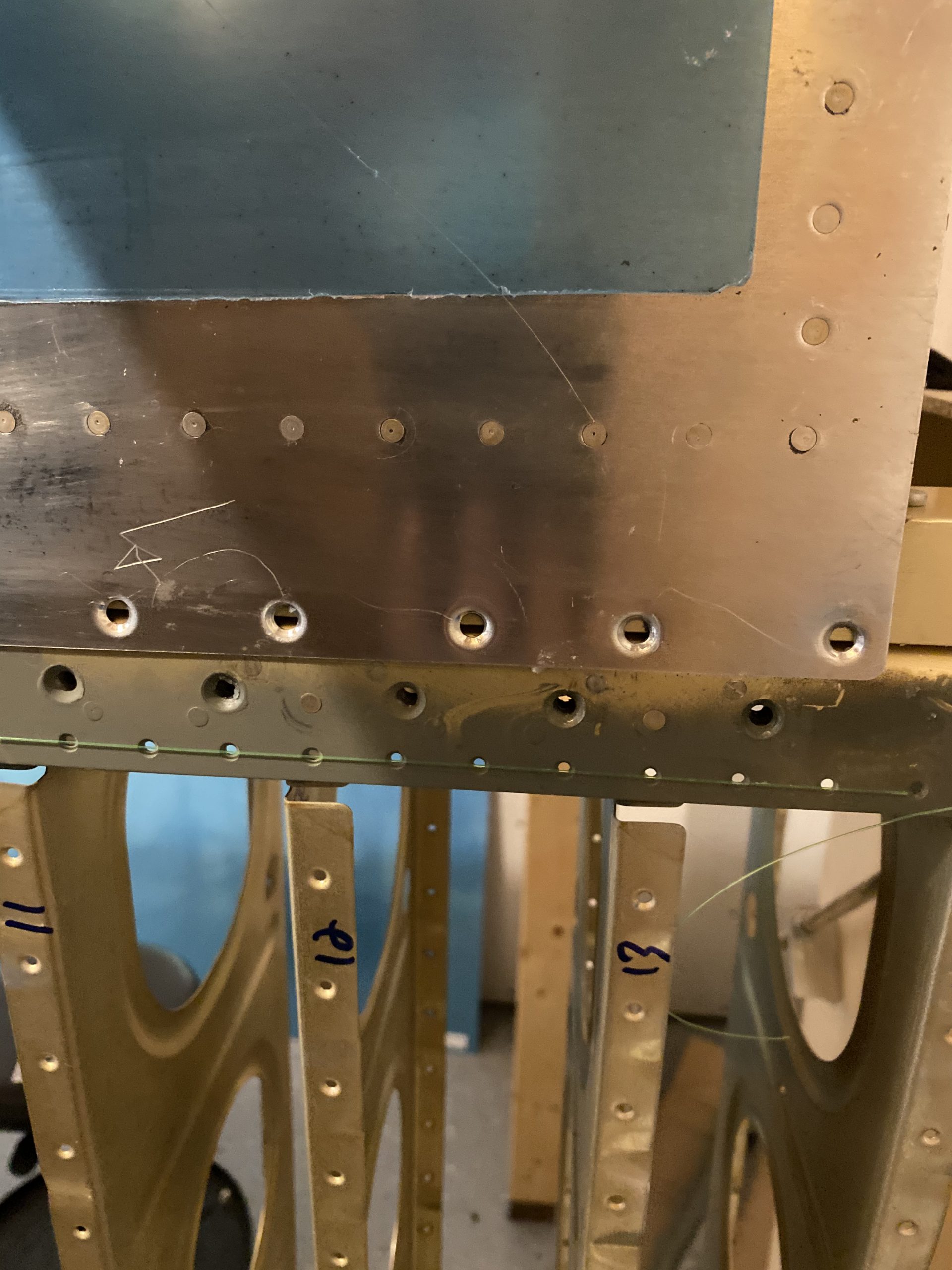
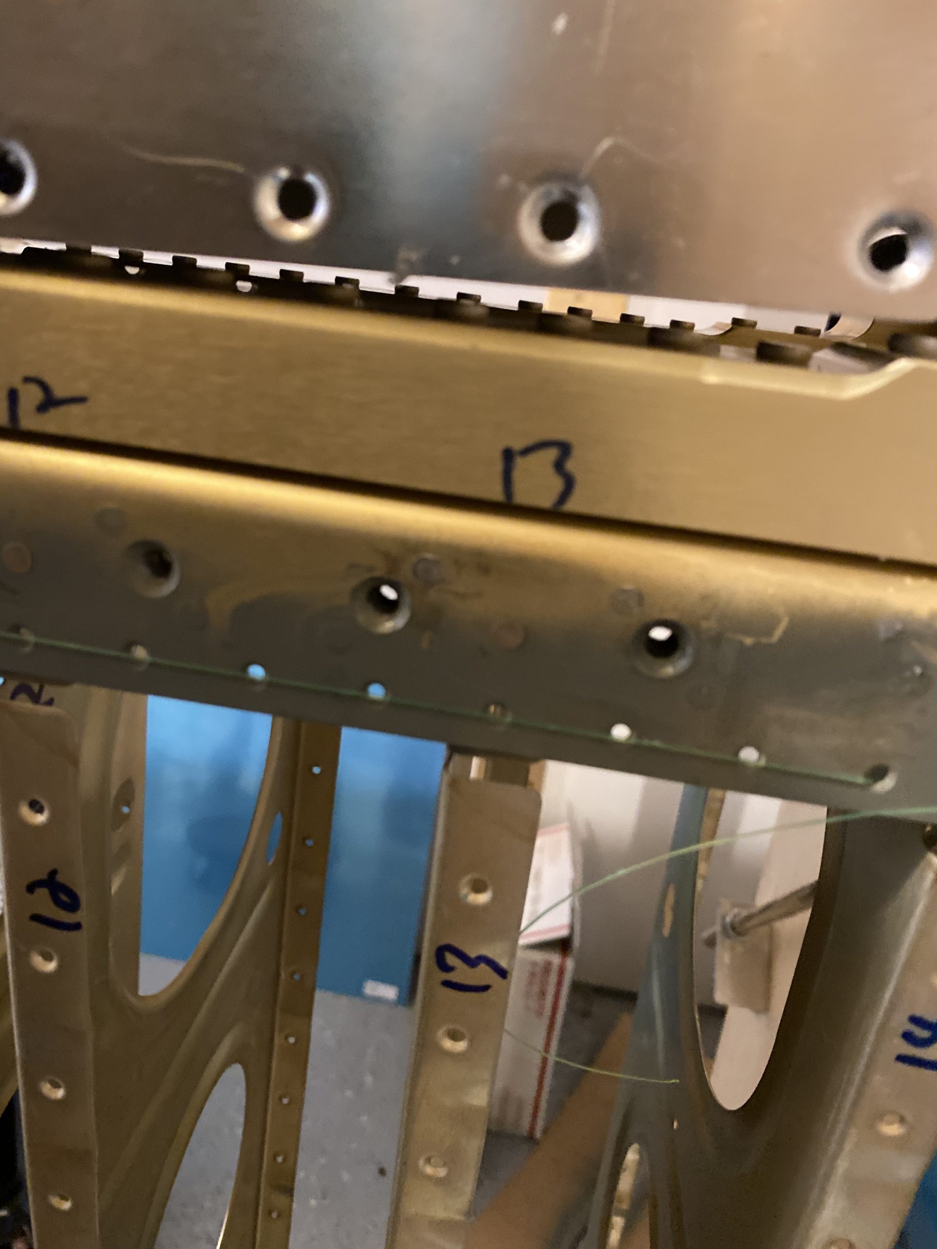
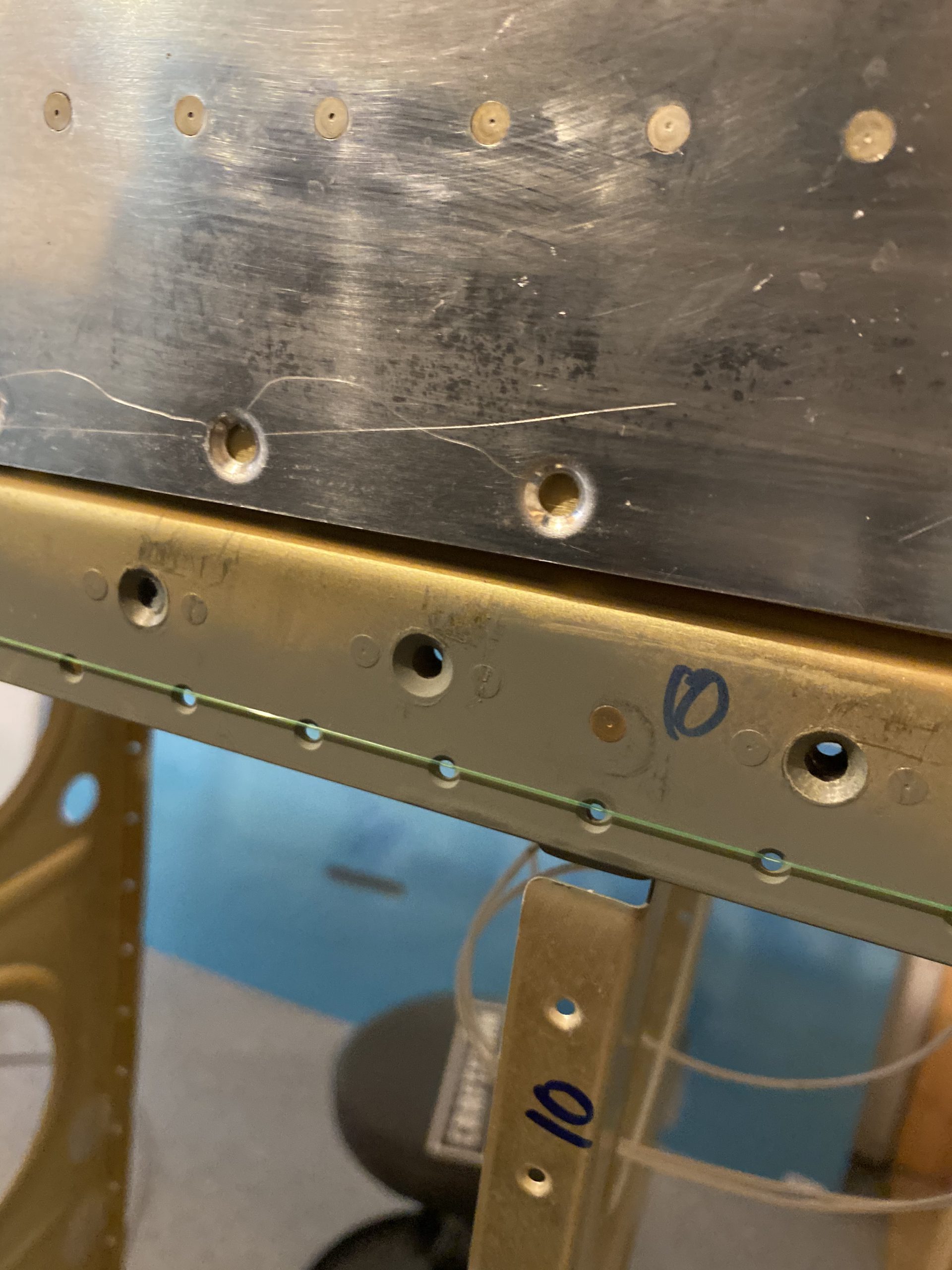
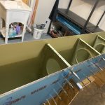
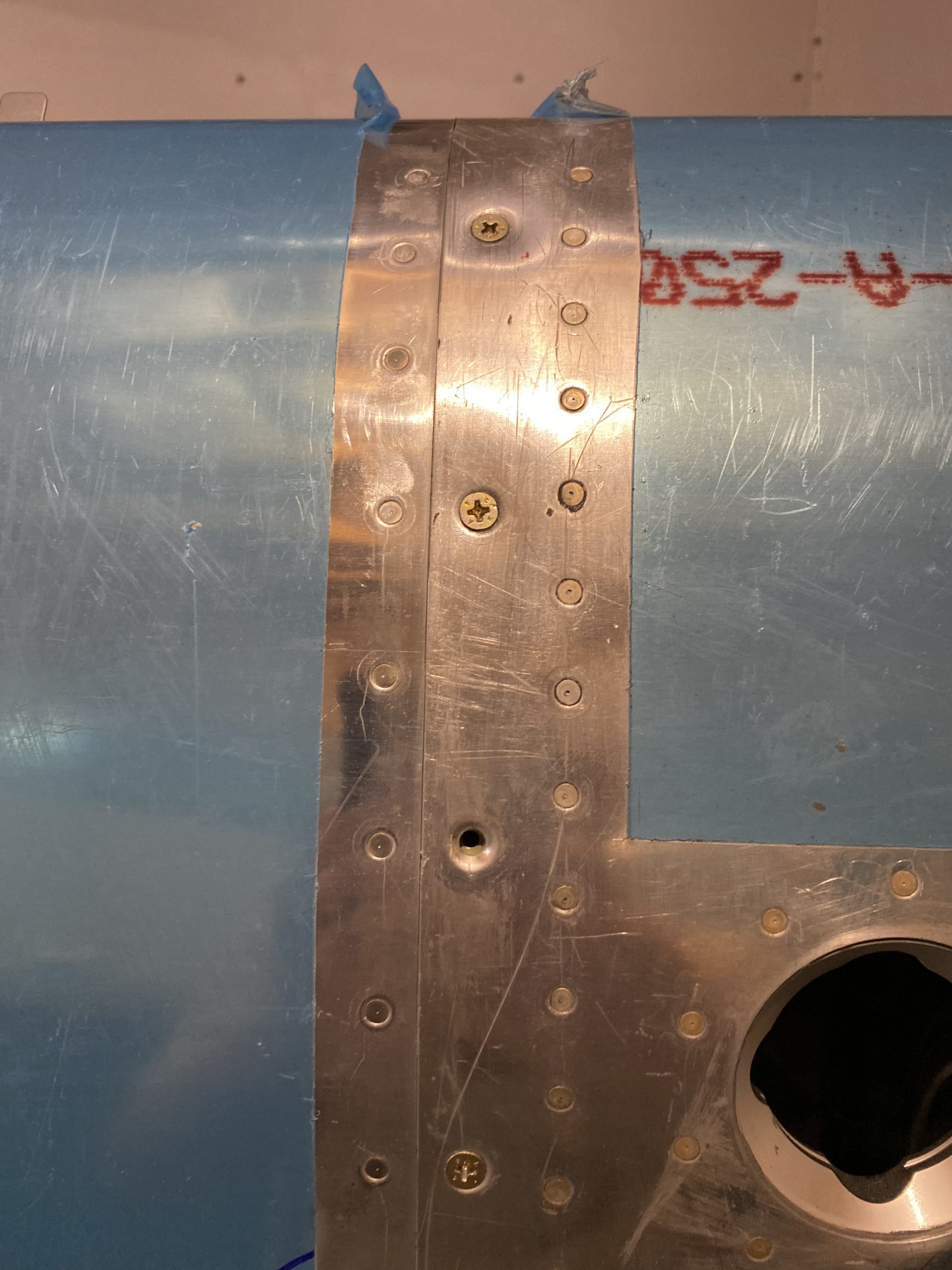
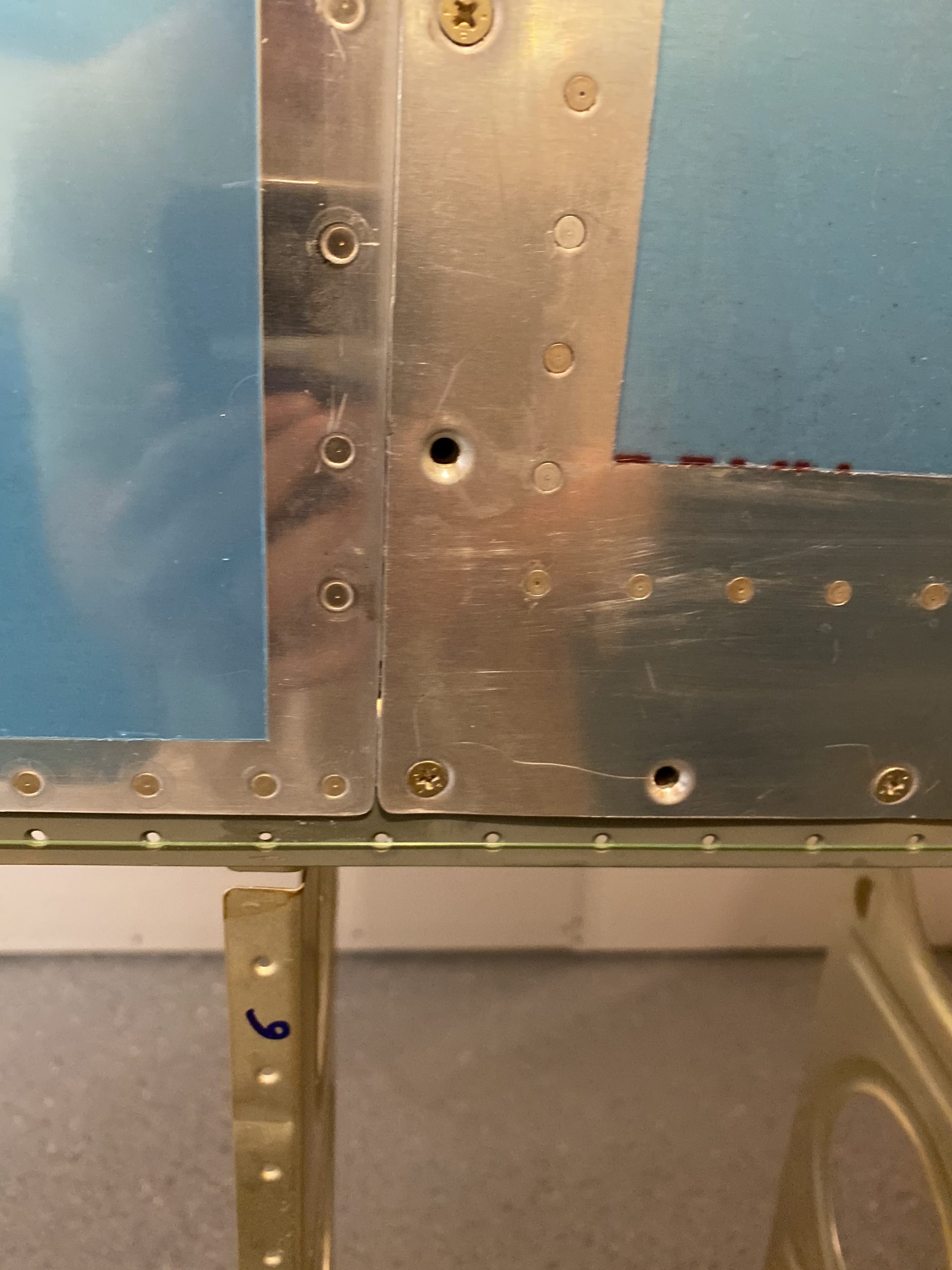
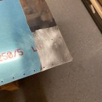
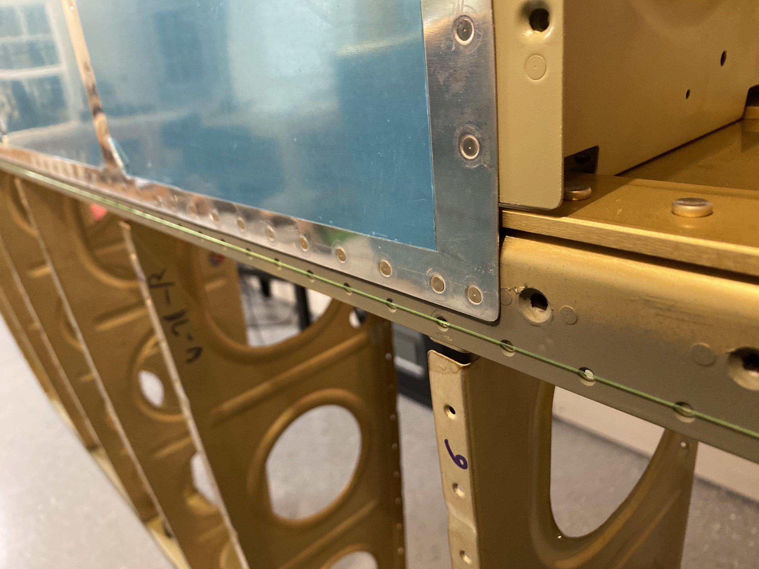
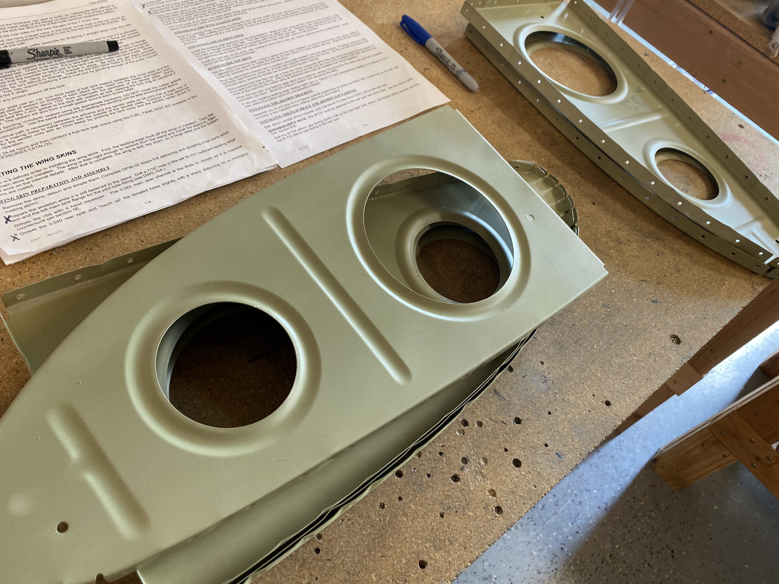
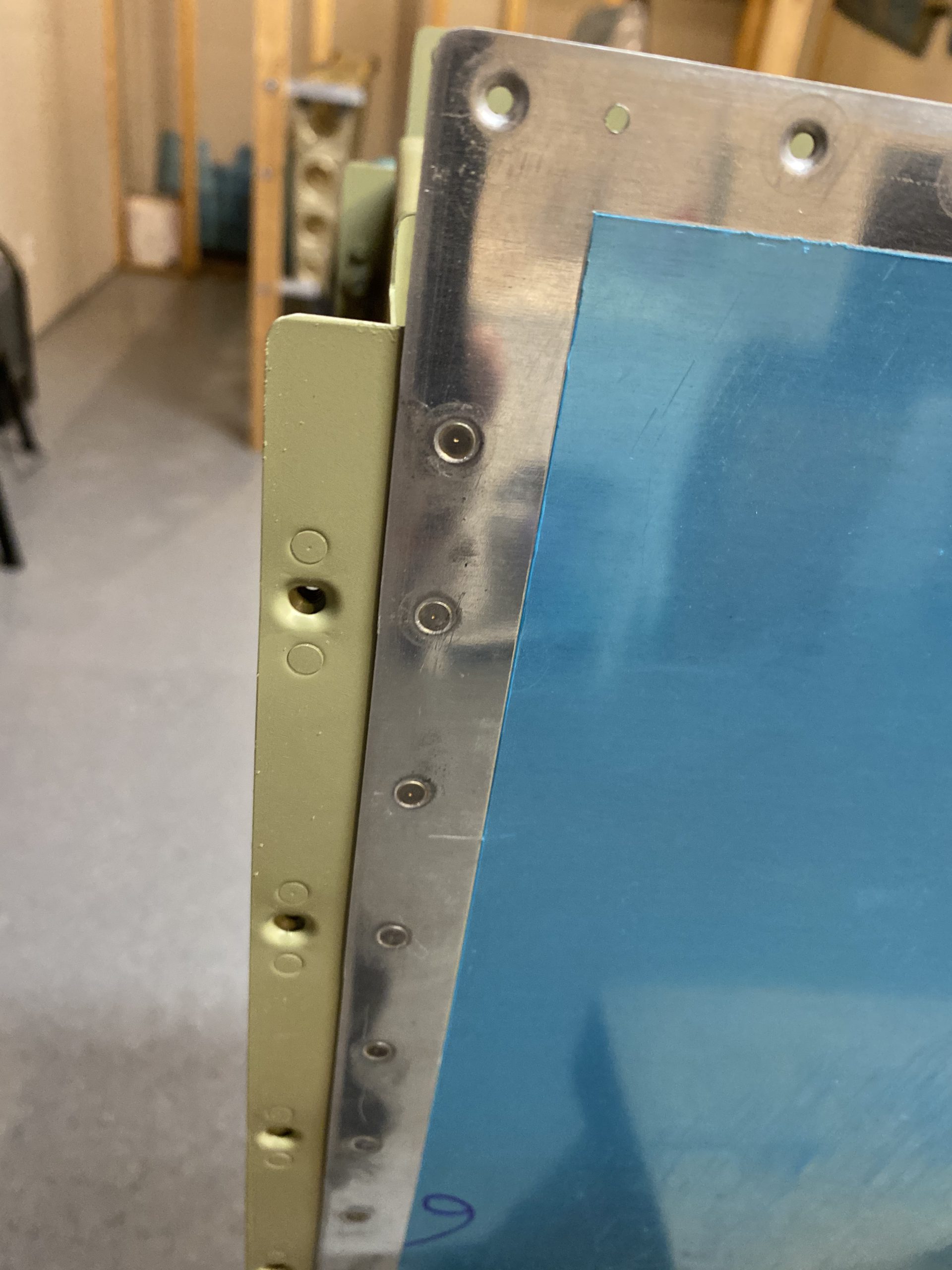
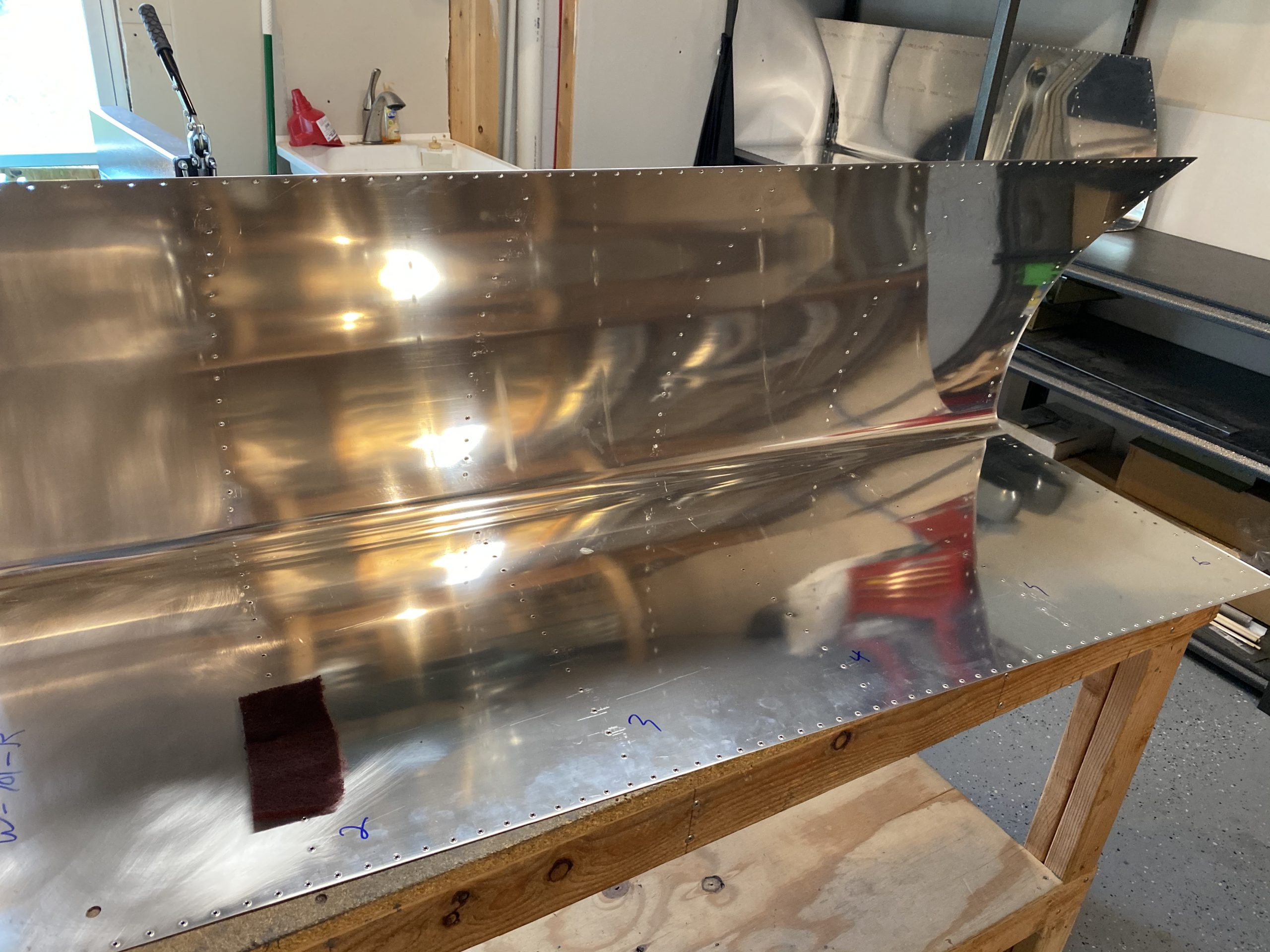
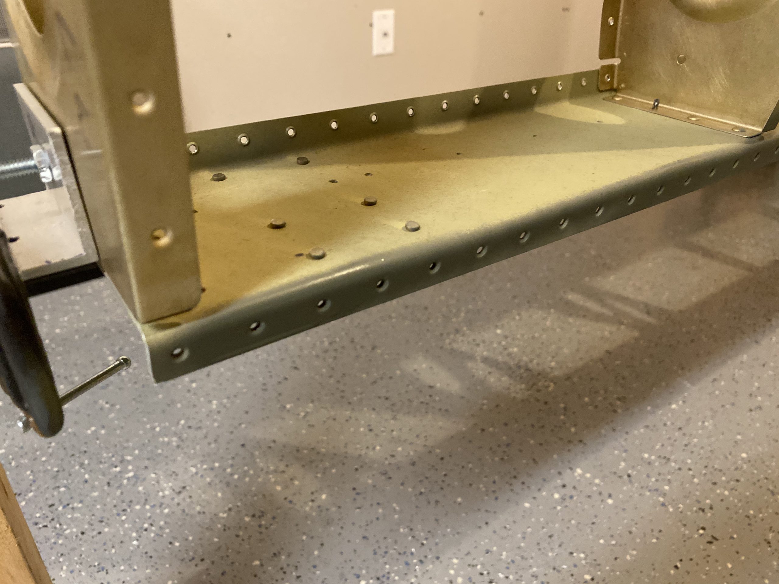
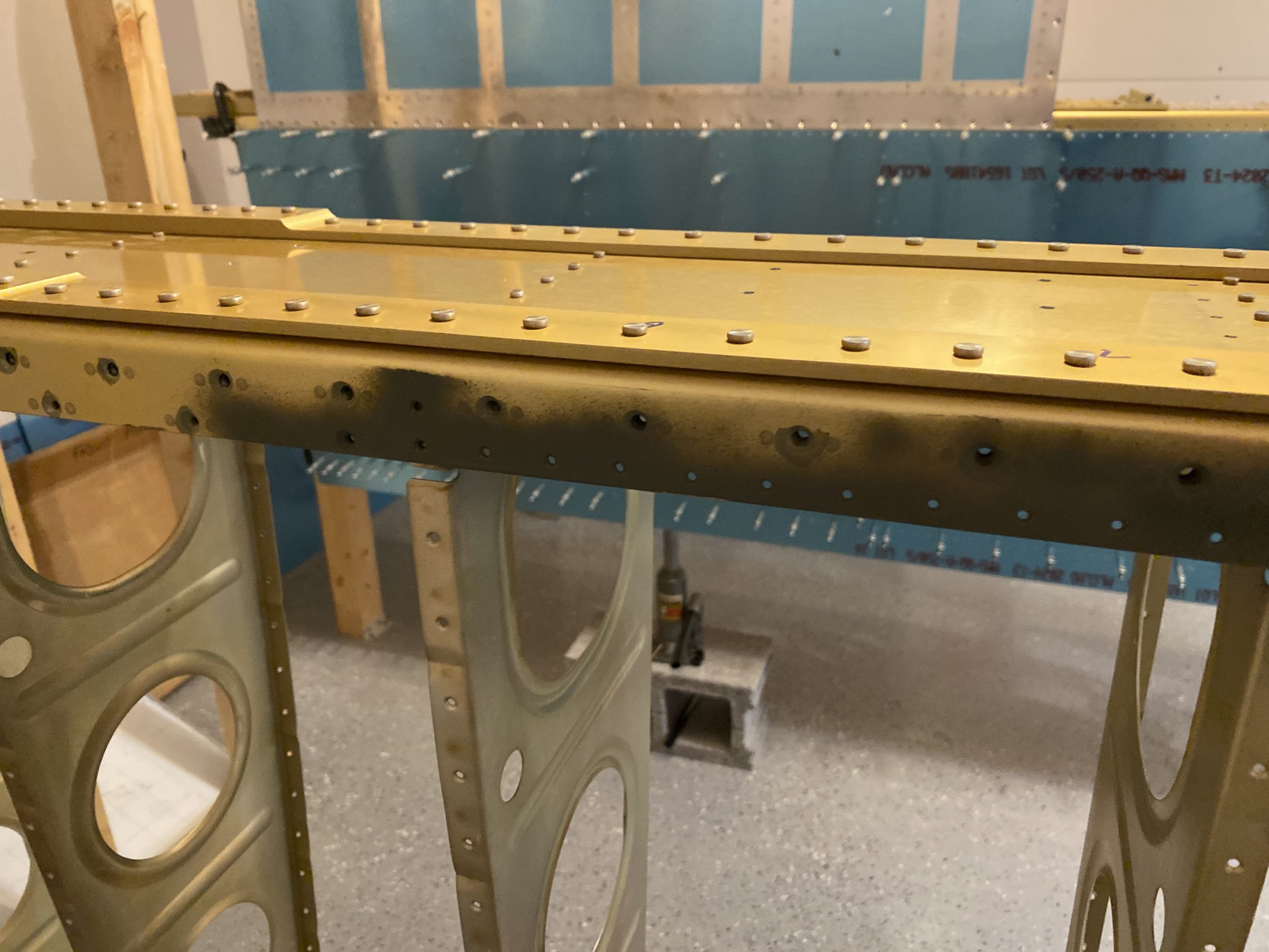
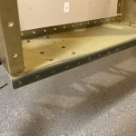
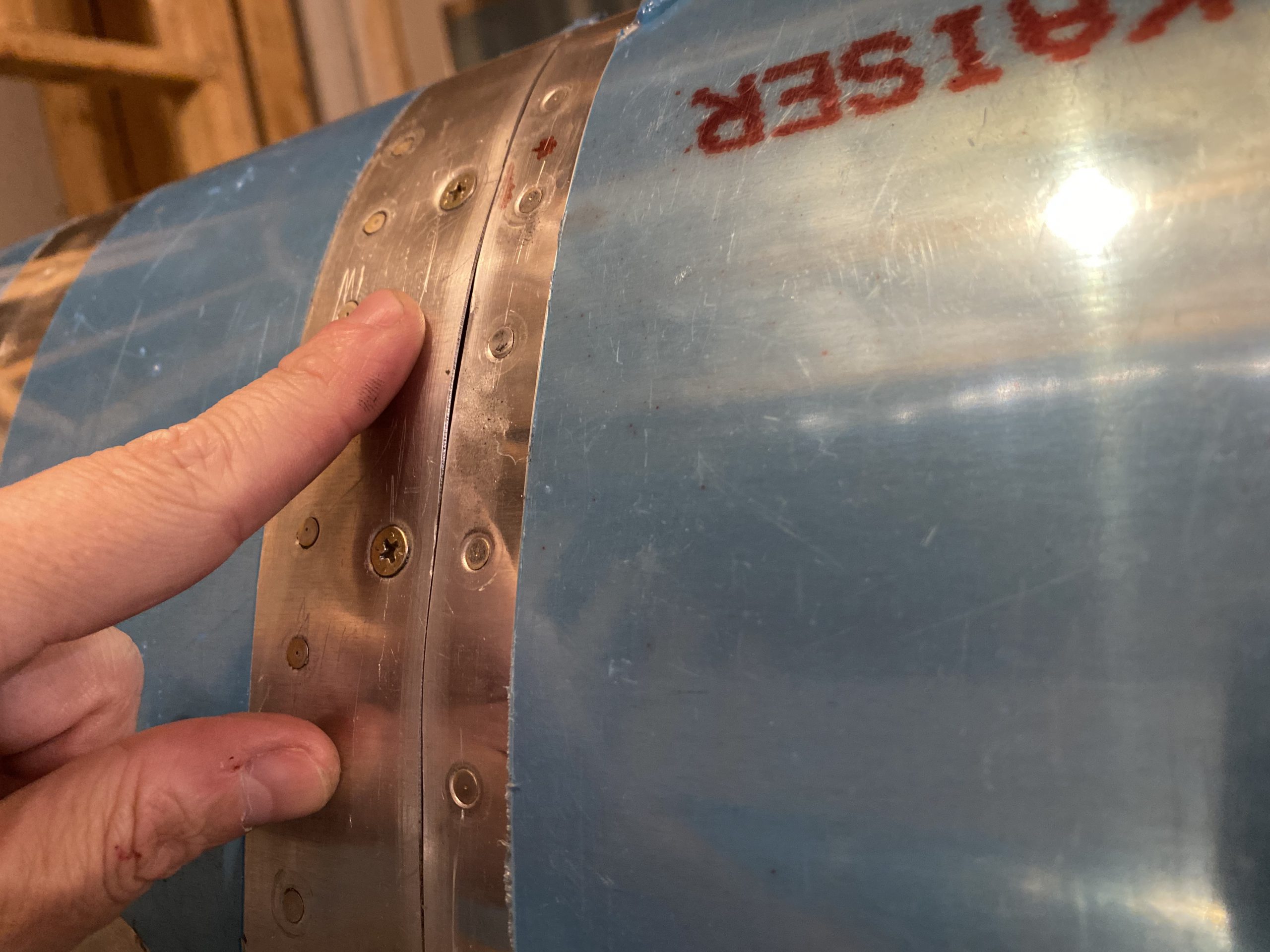
The tank to leading edge joint looks really nice.  Except for one tiny spot at the very leading edge where there is a slight buge in the tank skin, or possibly a dip in the leading edge skin (maybe both?).  It’s not very bad, and I am not sure I could get it any better to be honest.  There isn’t any sealant under there causing it.  So, I will leave it as it is, and see if the paint shop can get it straight when they remove the tanks to do the final painting (after I fly off the phase I and II testing).  What do you think?  does it look bad?

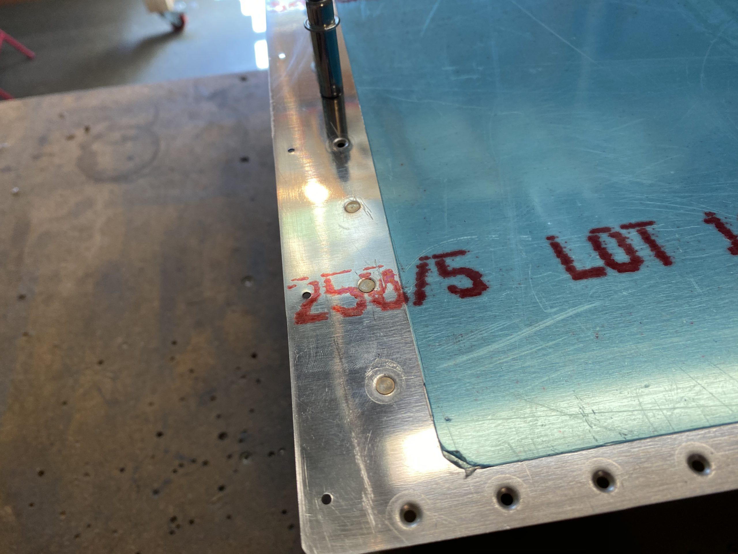
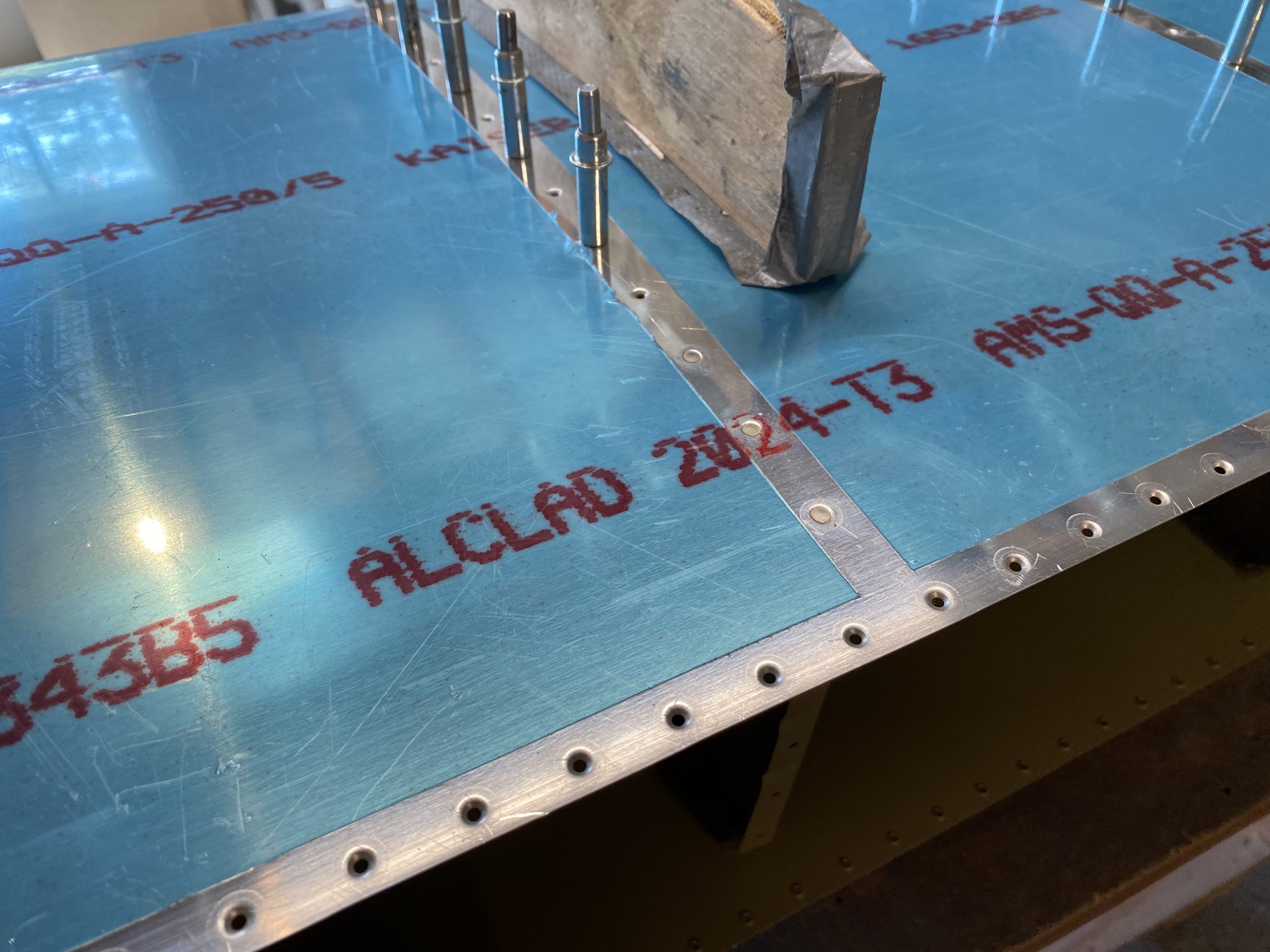
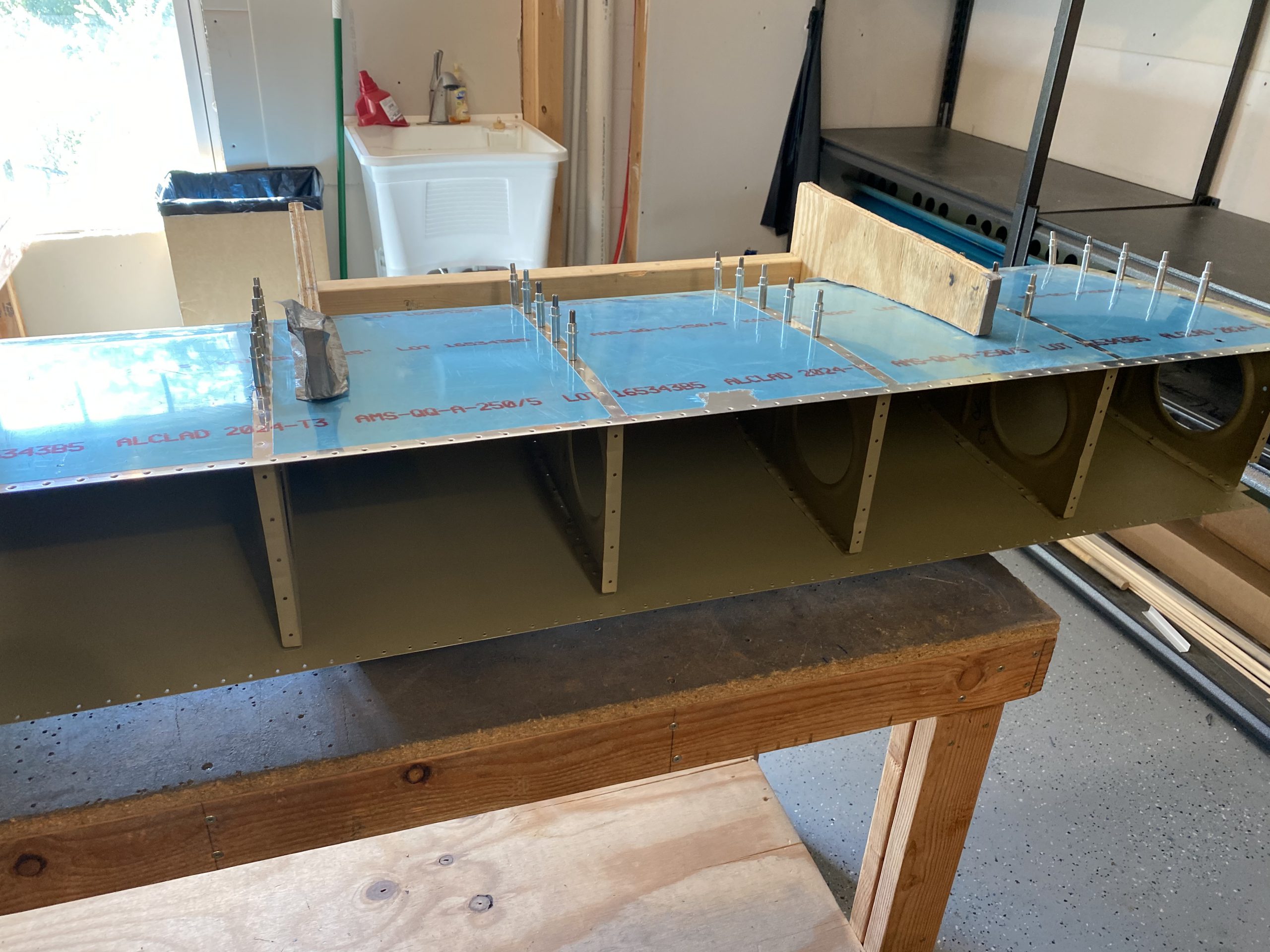
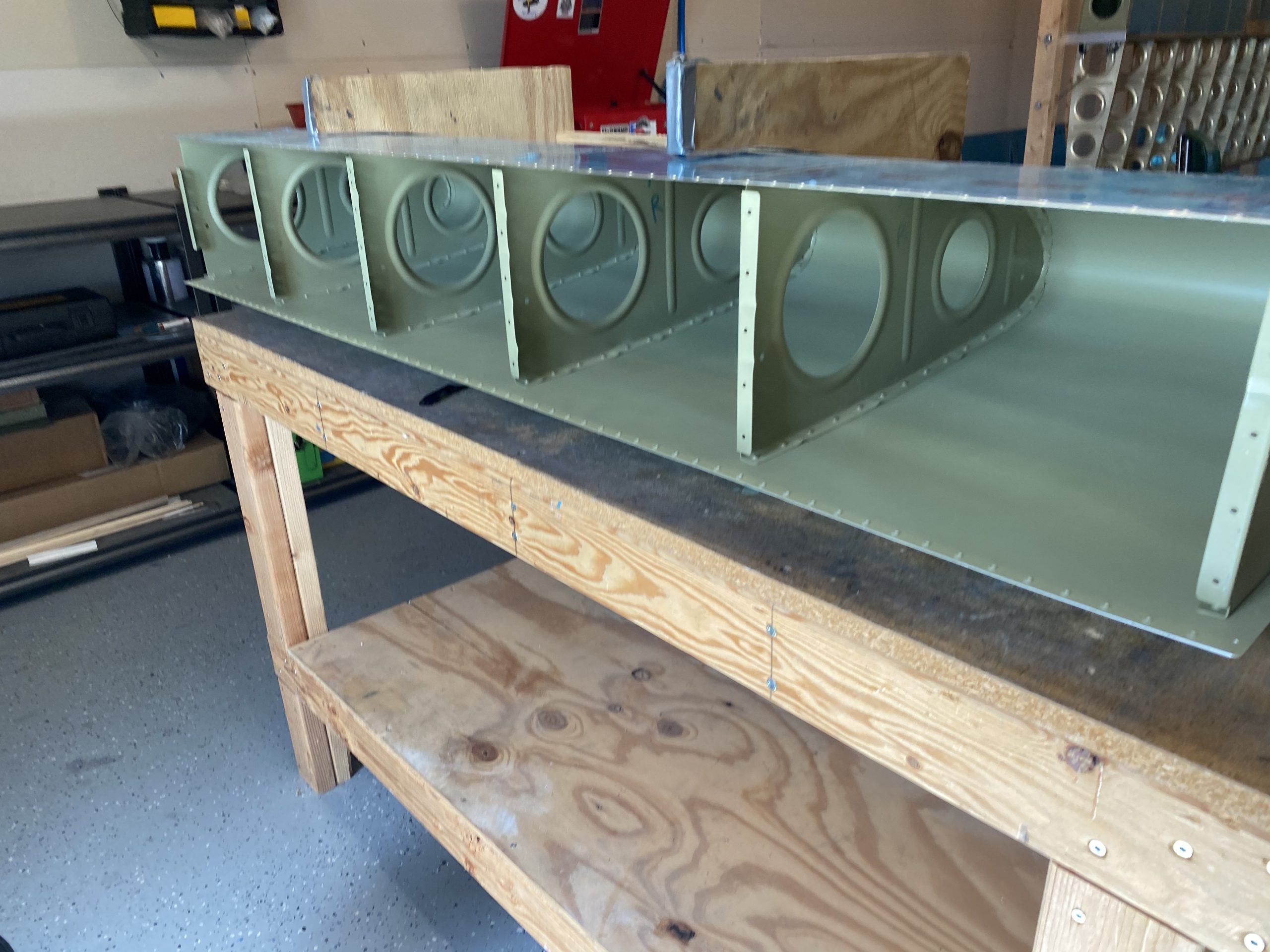
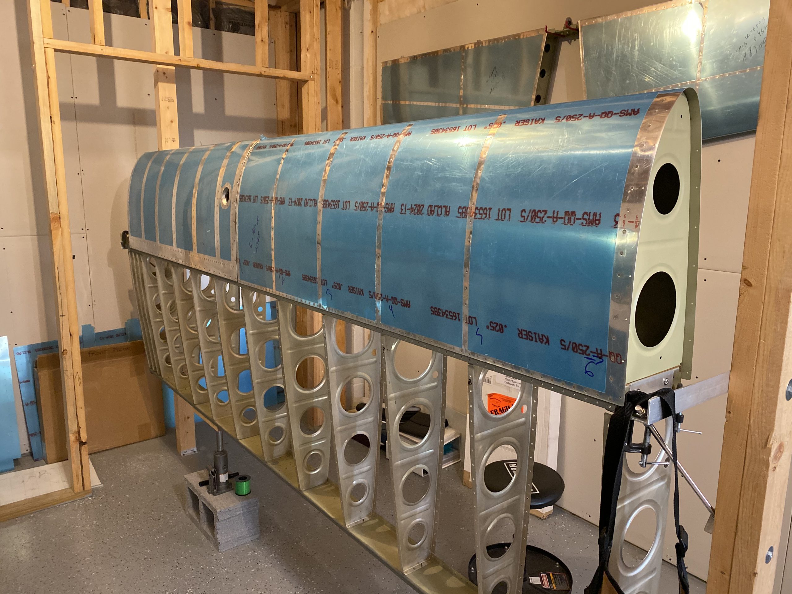
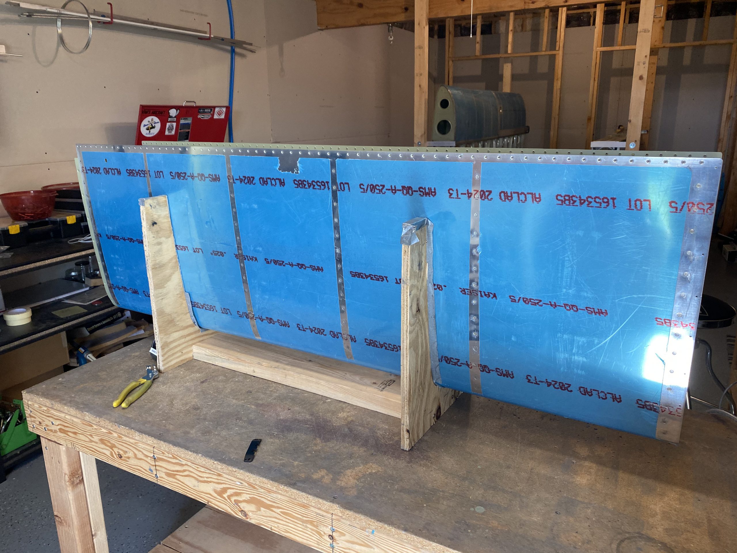
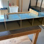
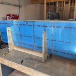
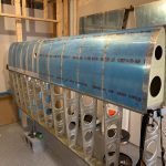
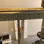
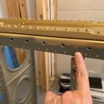
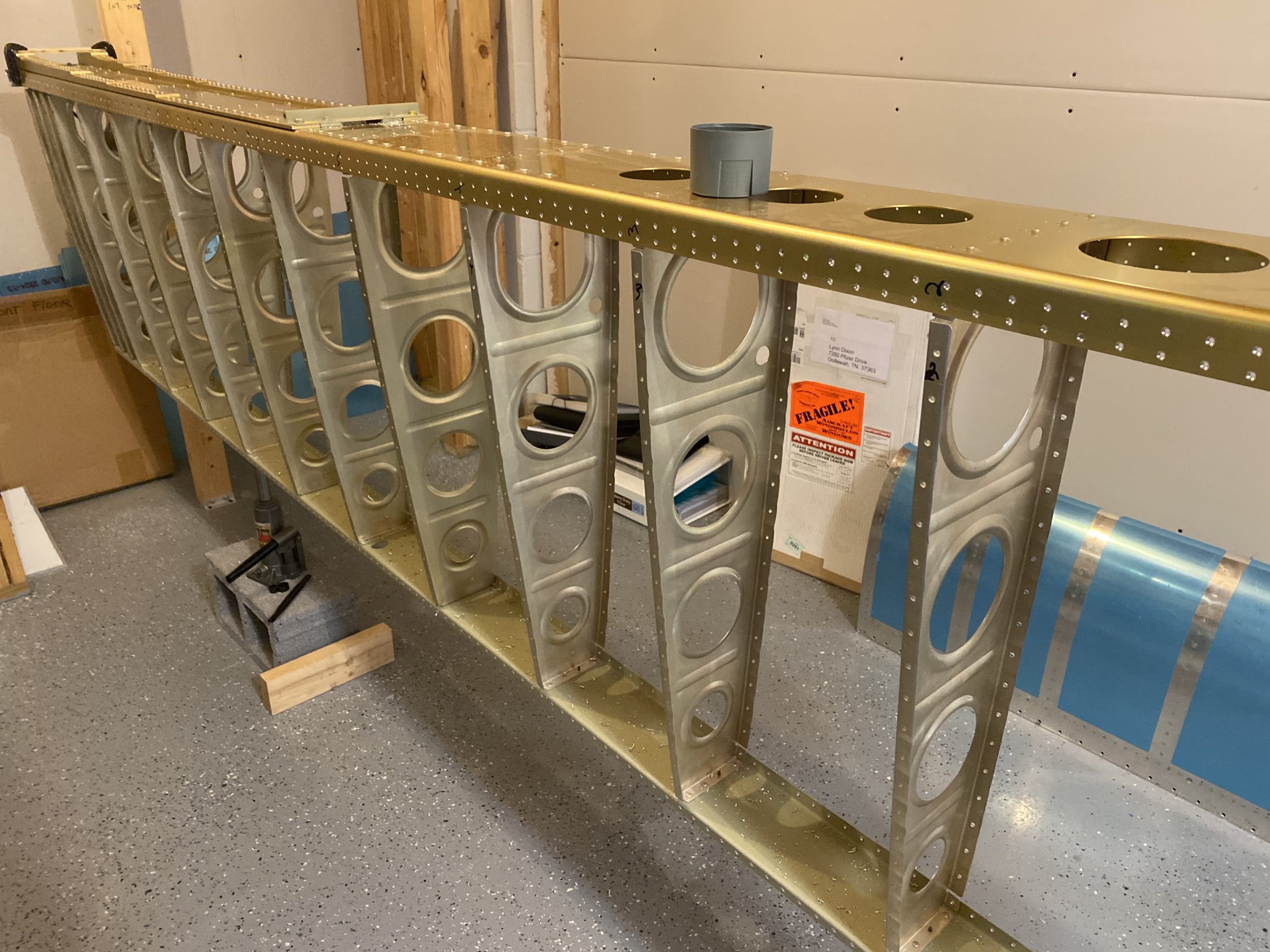
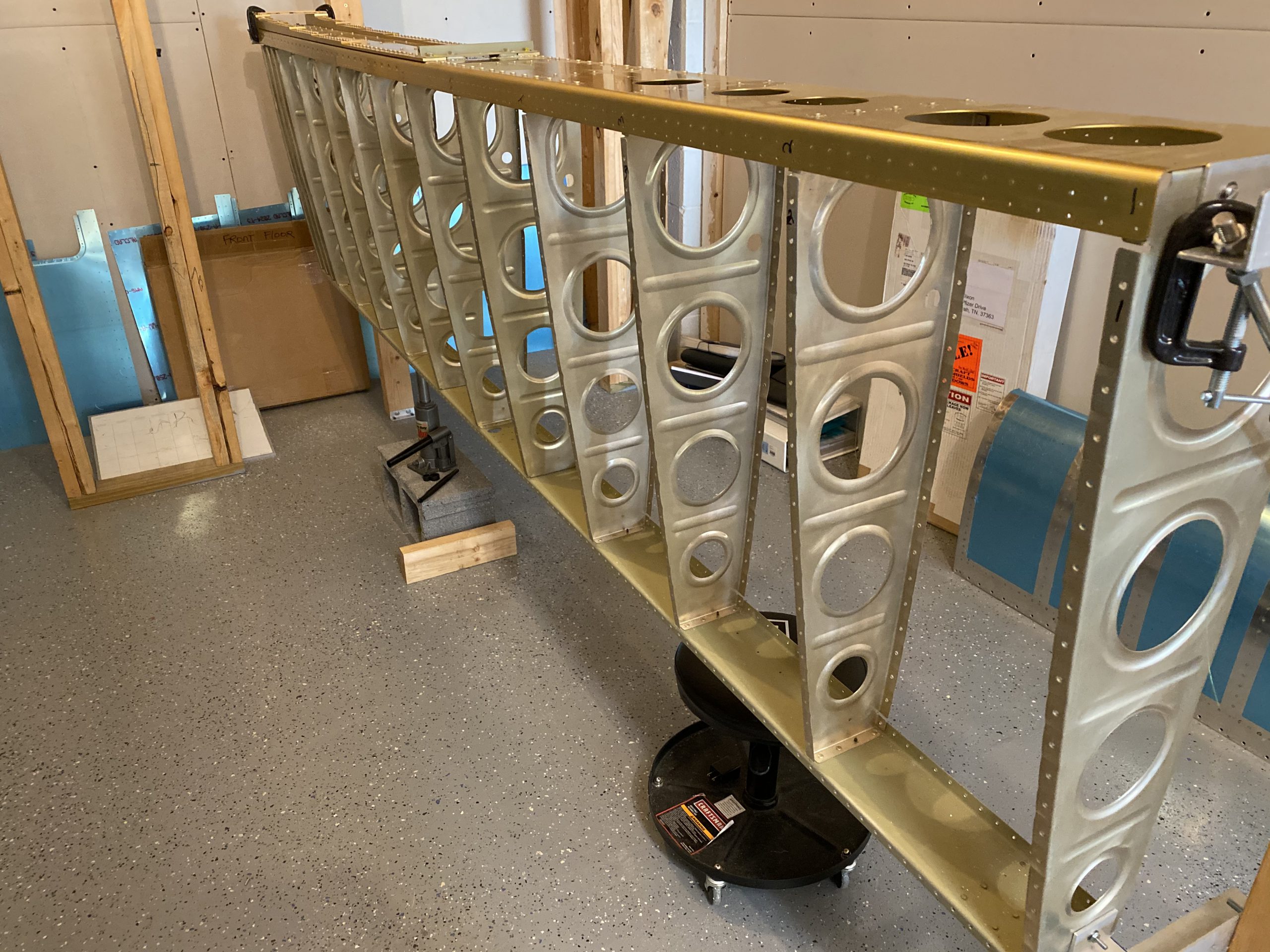
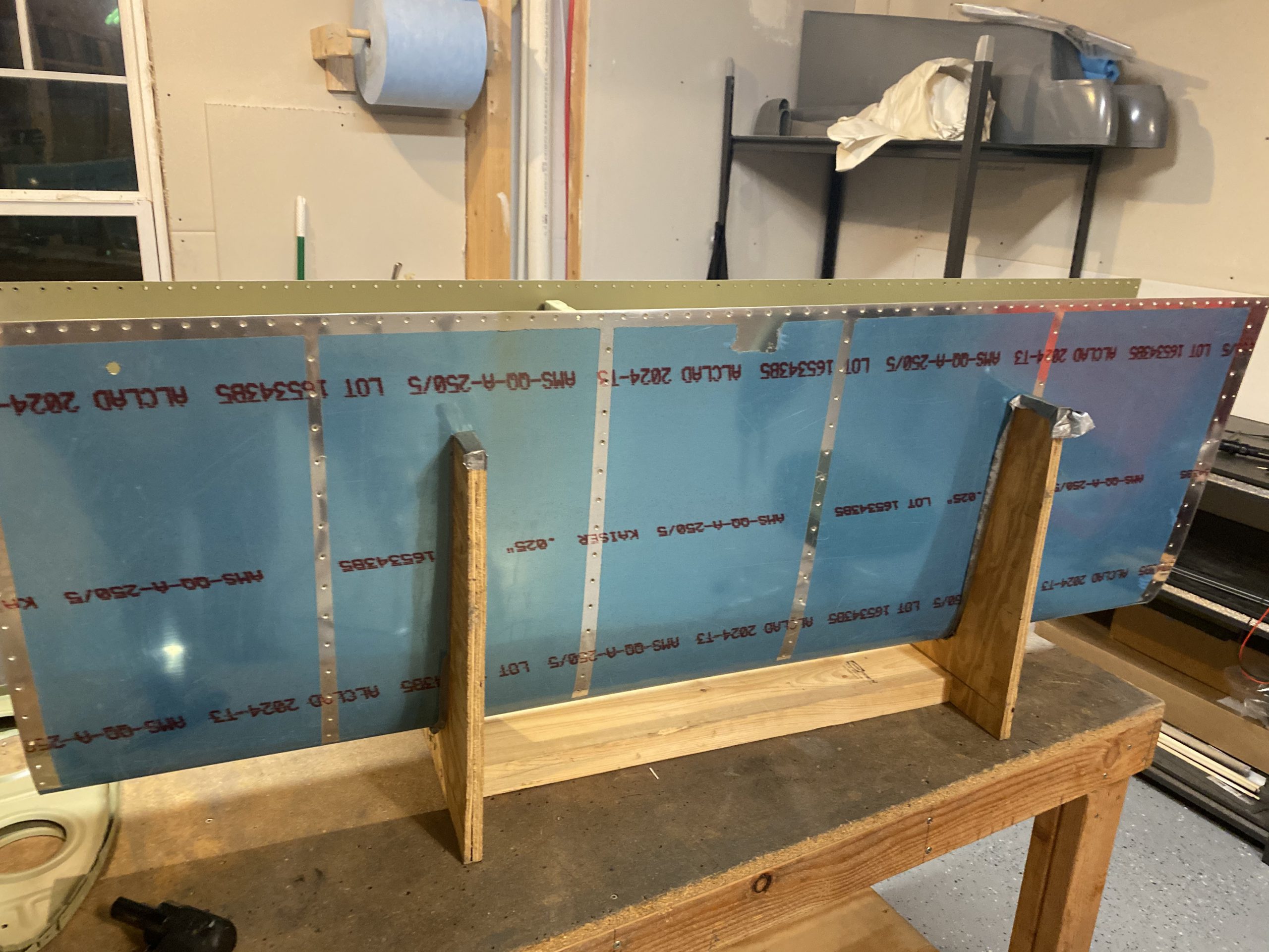
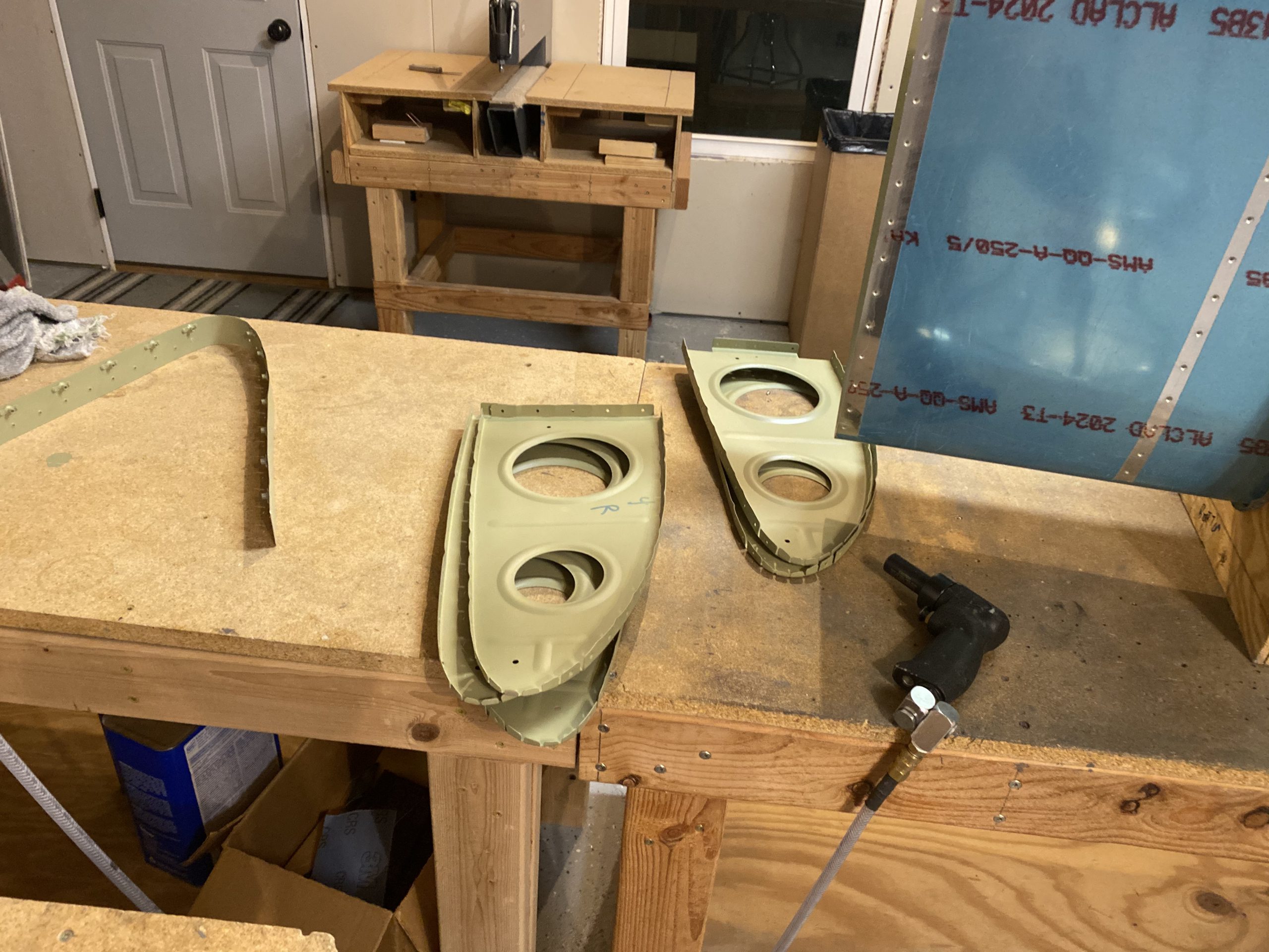
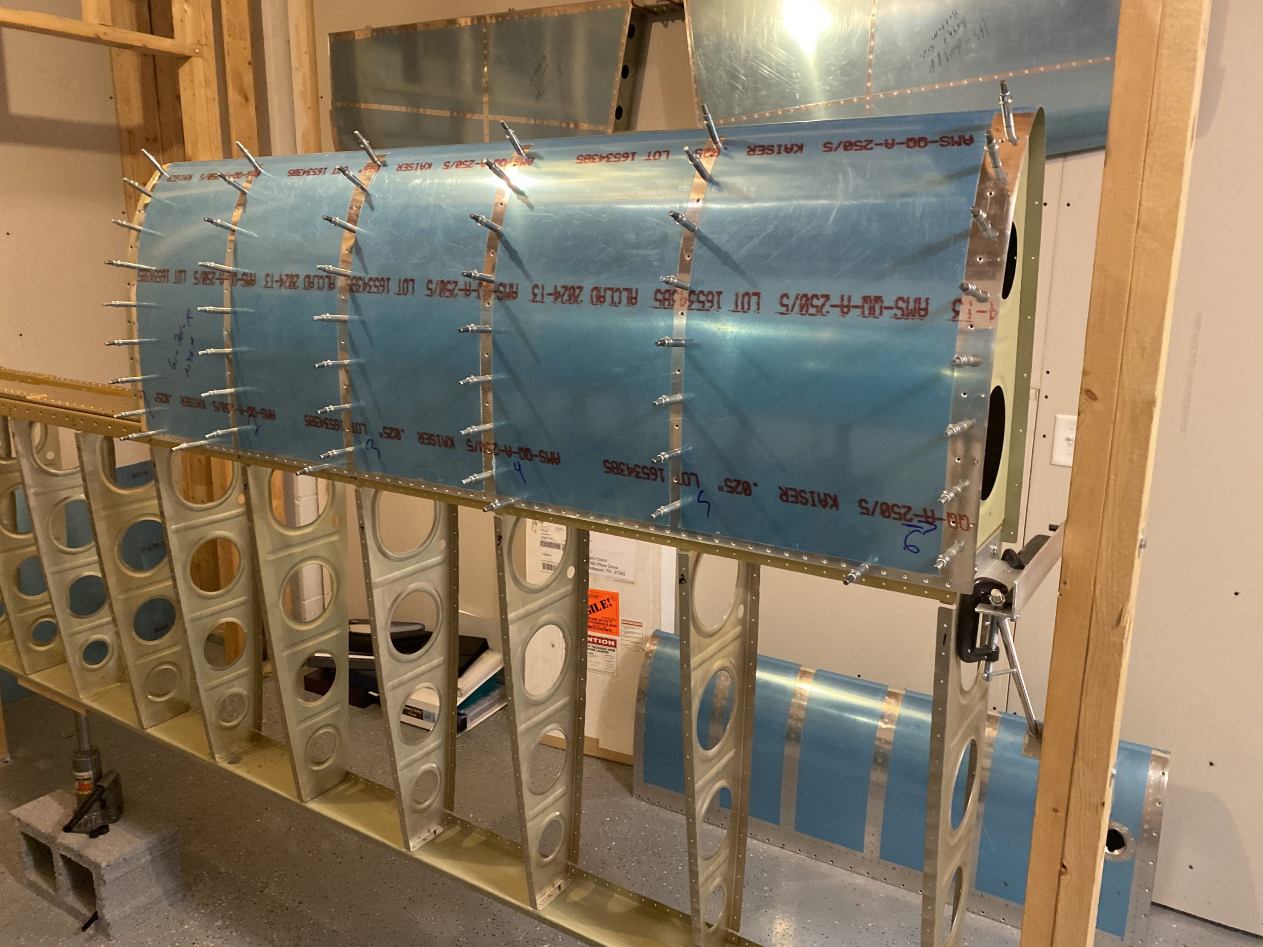
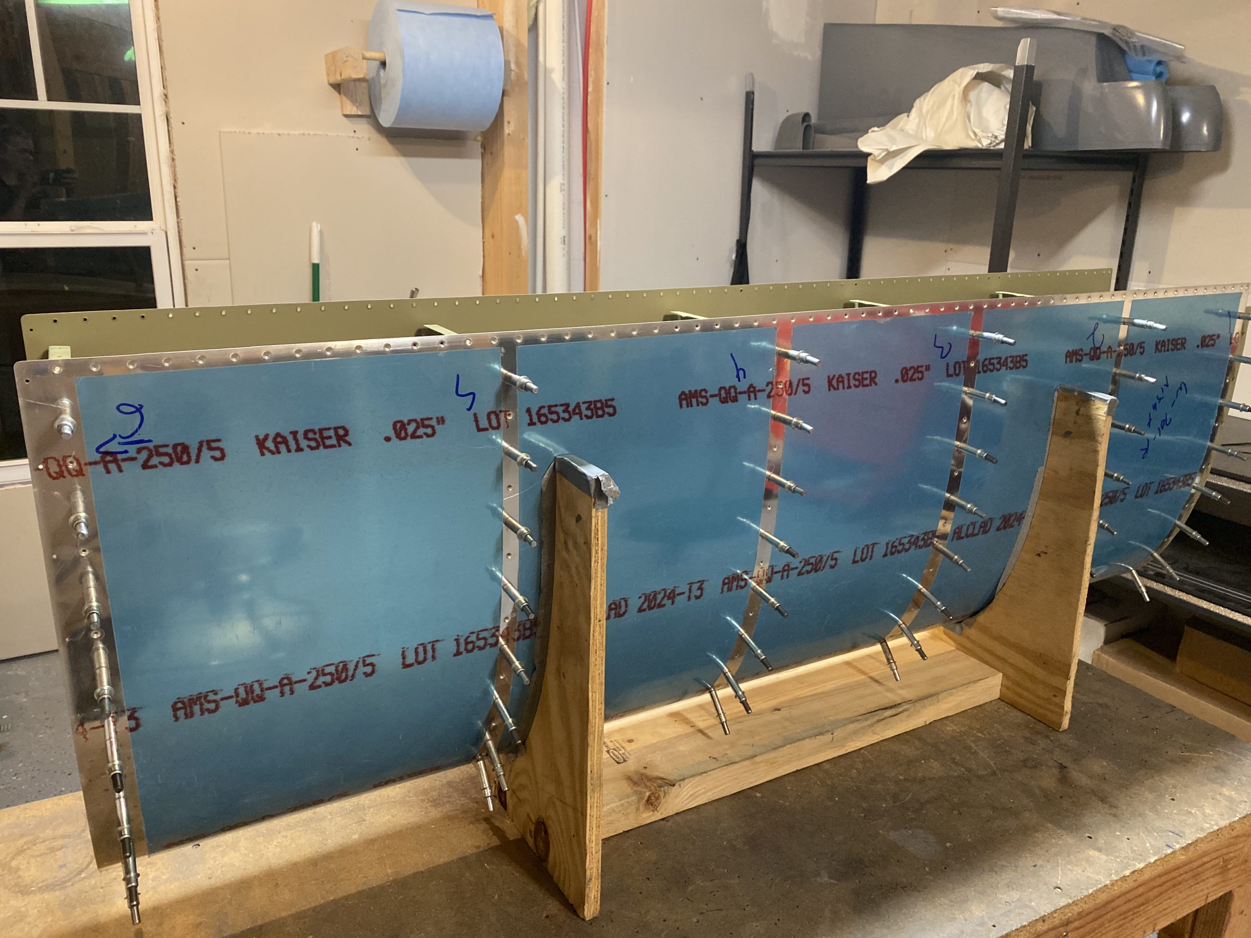
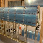
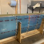
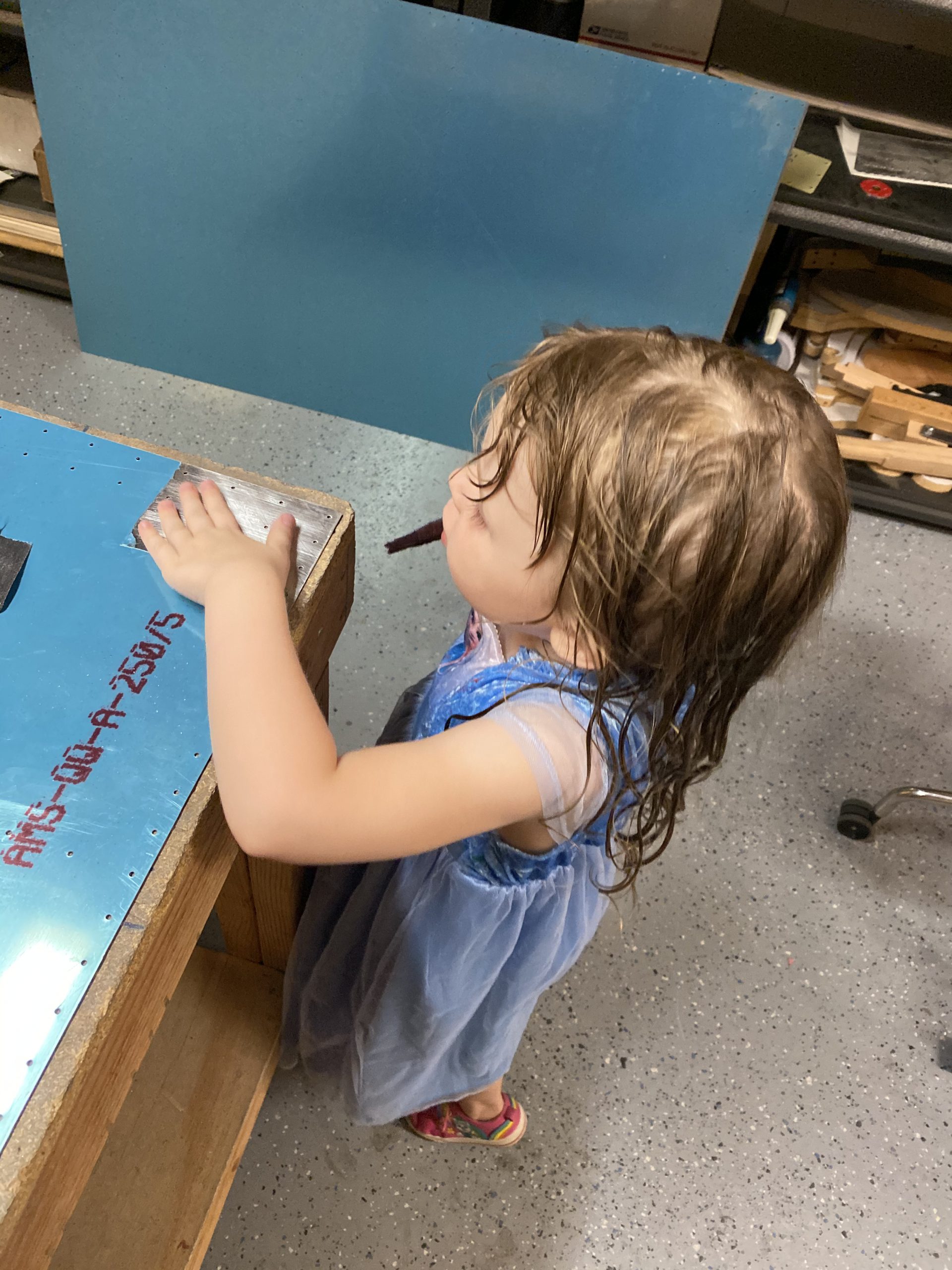
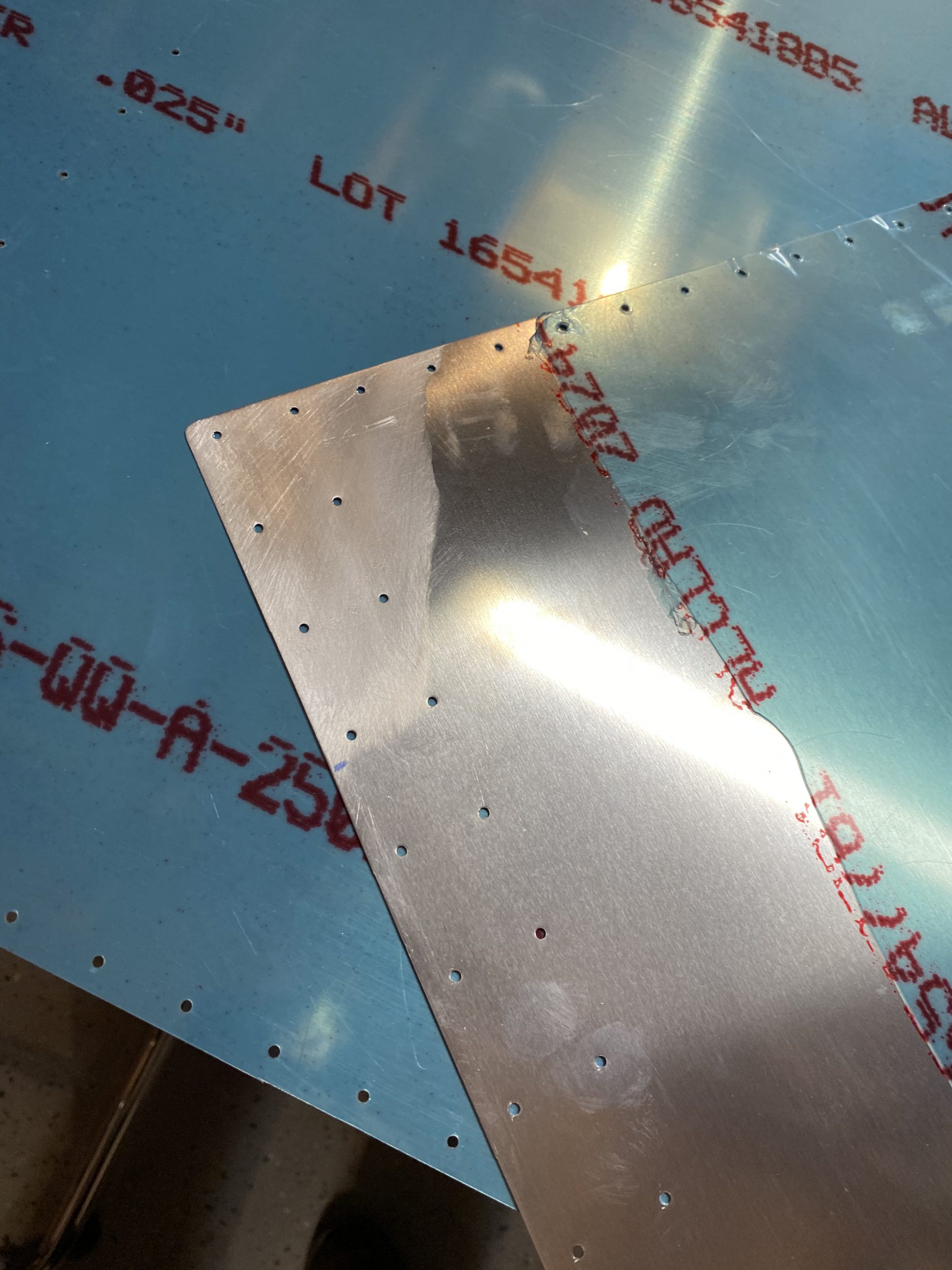
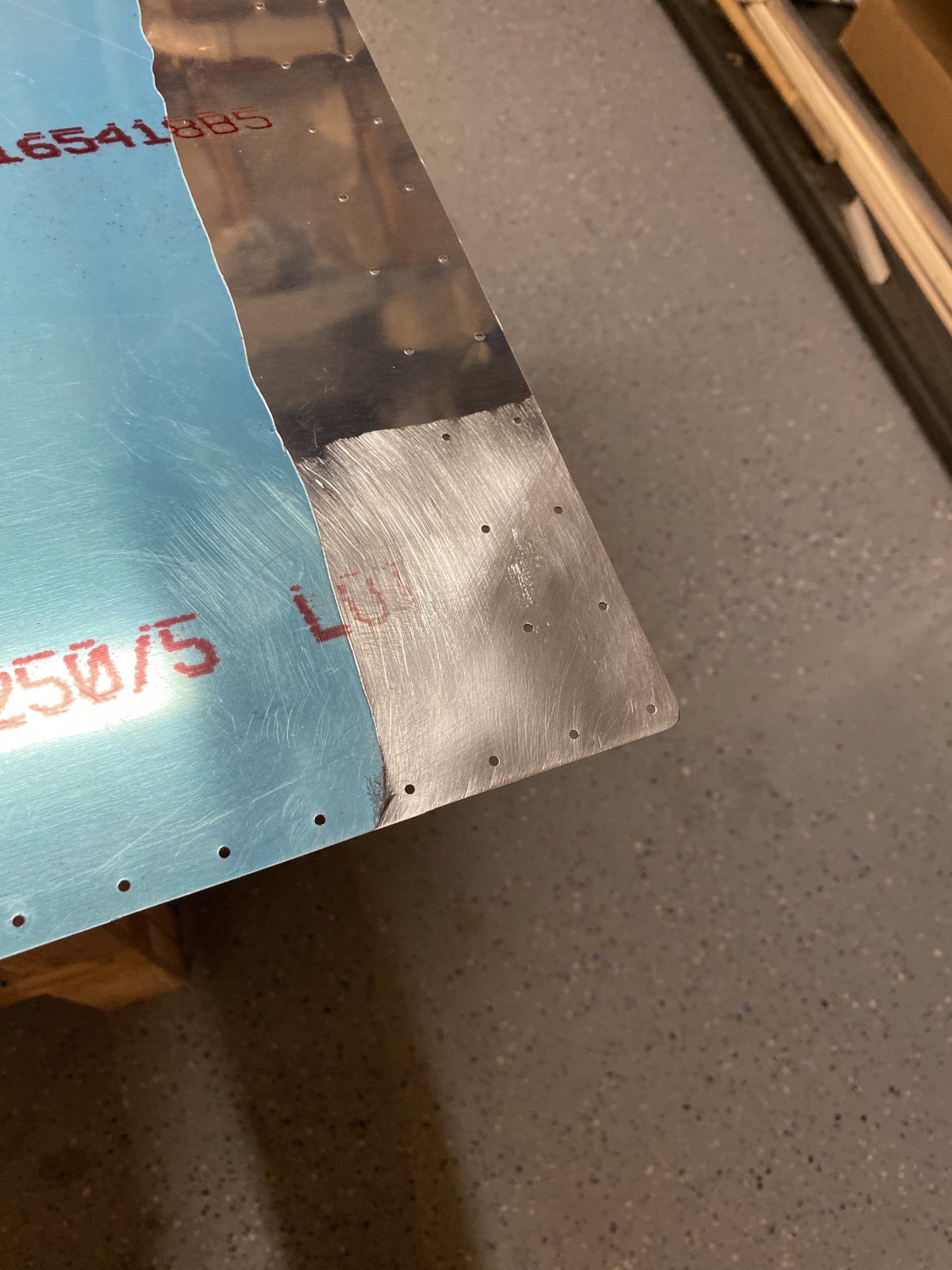
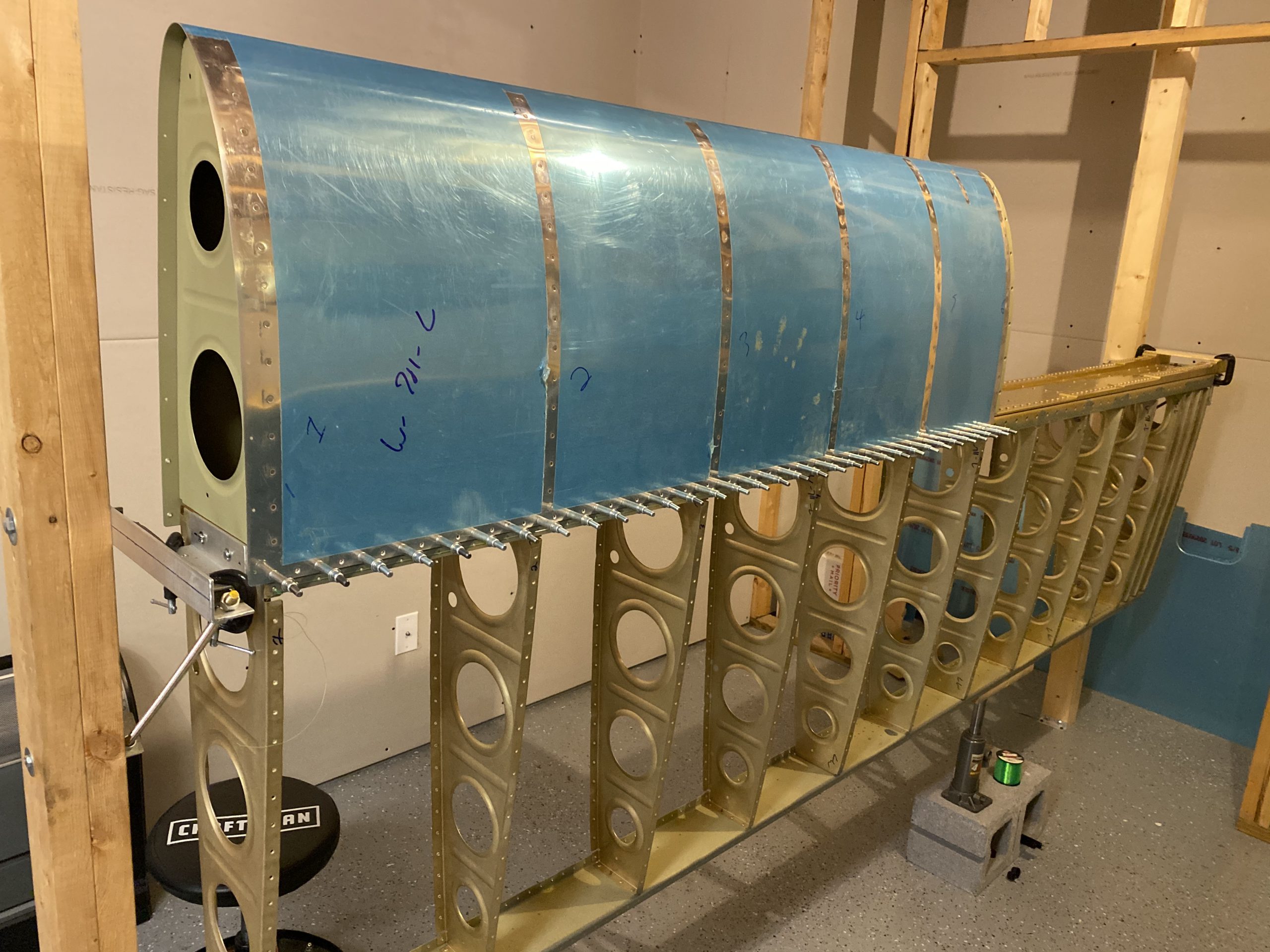
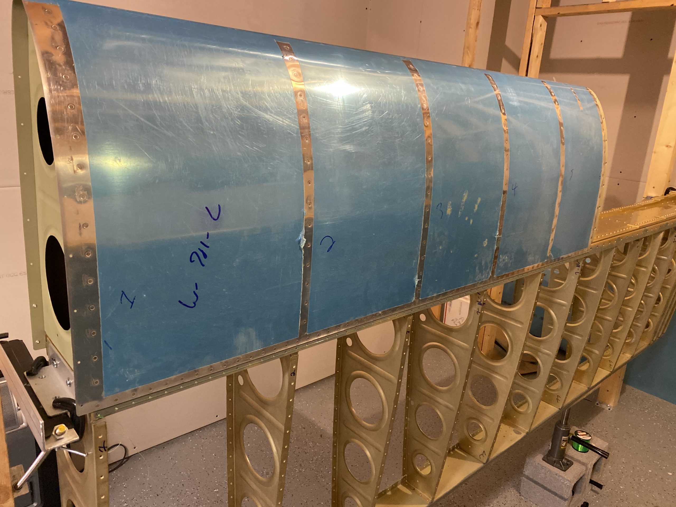
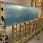
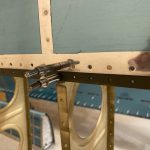
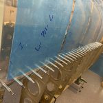
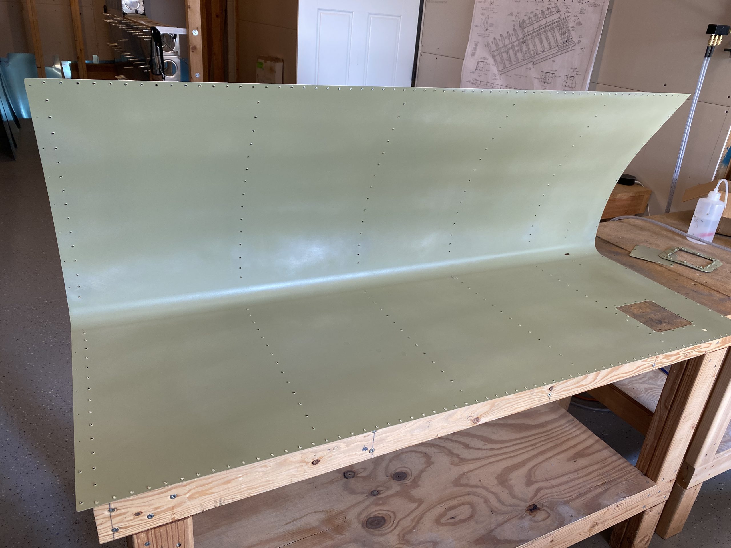
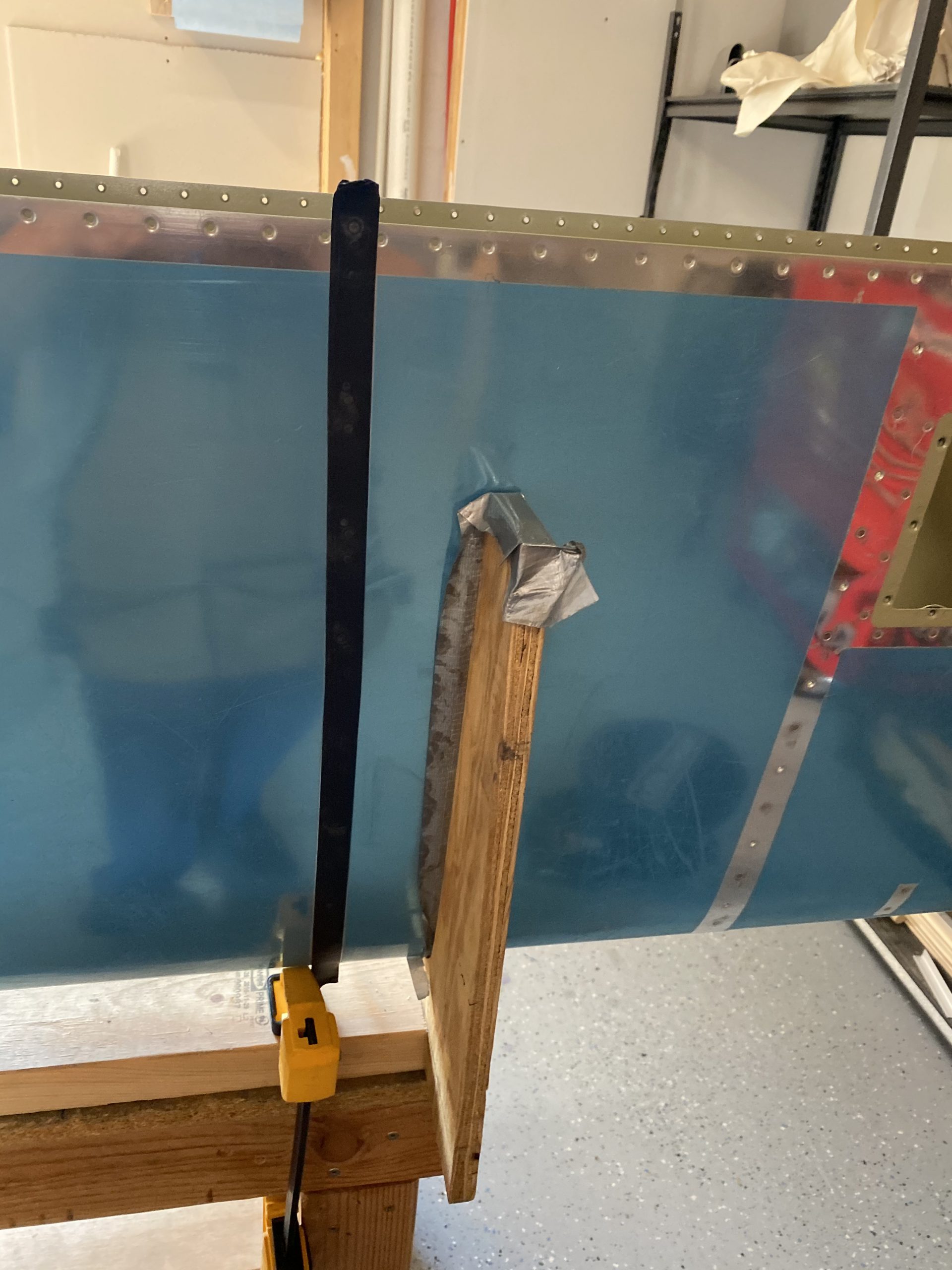
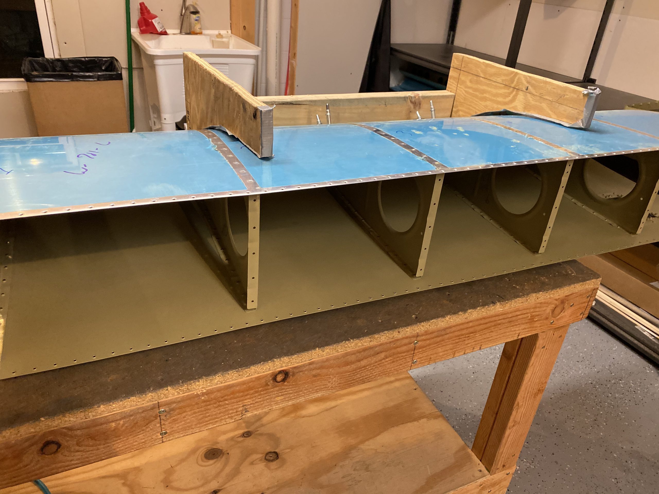
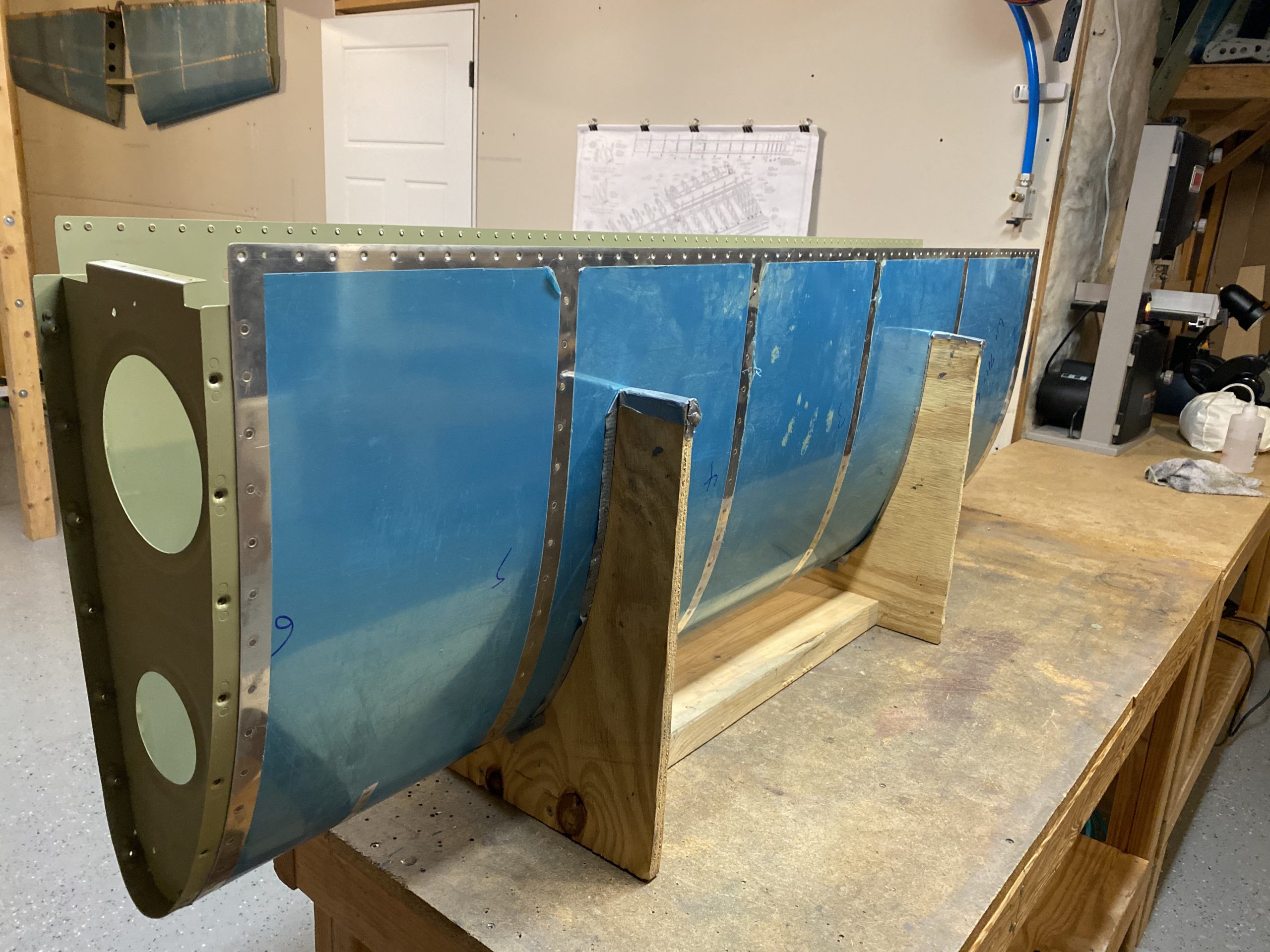
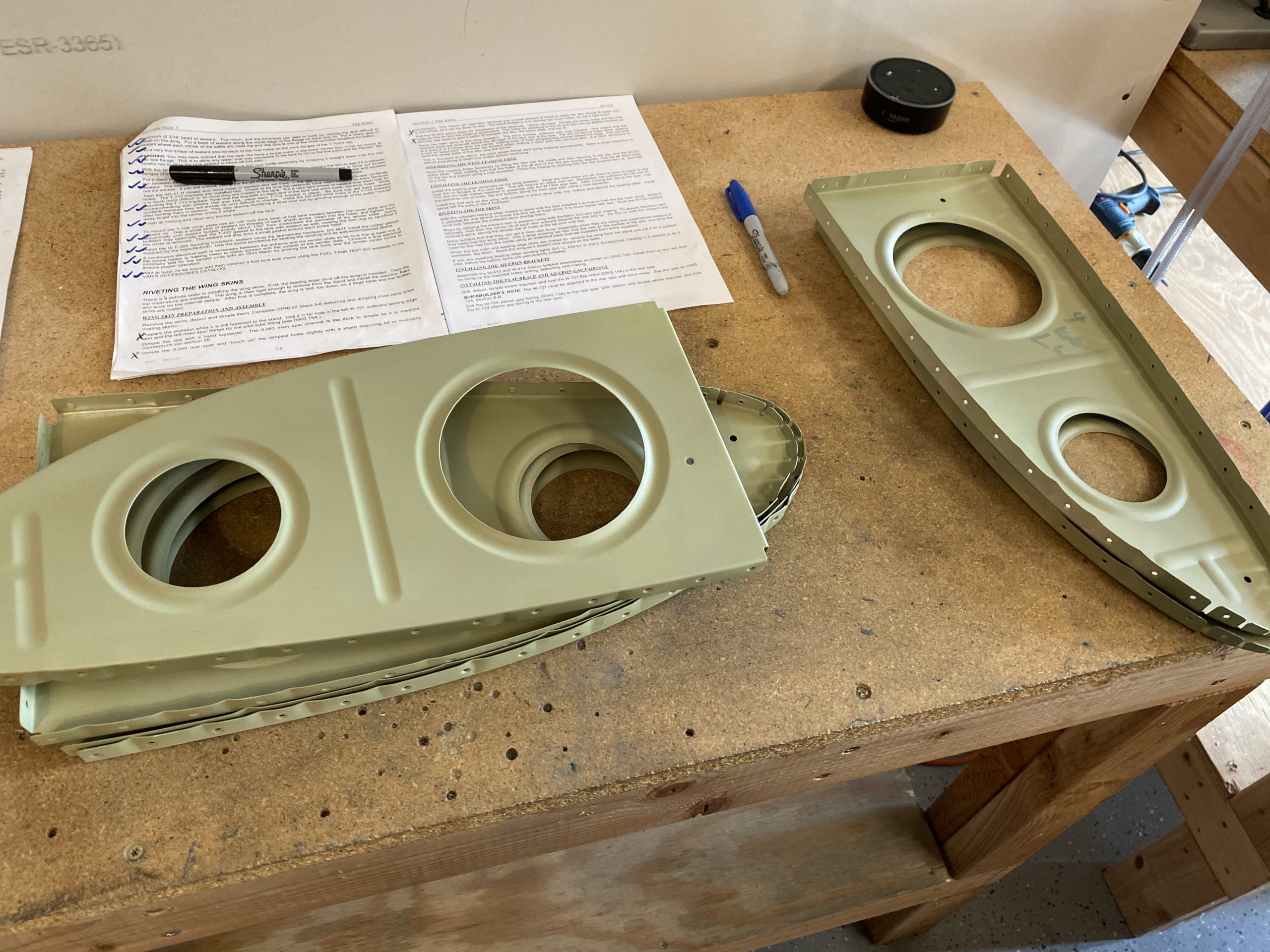
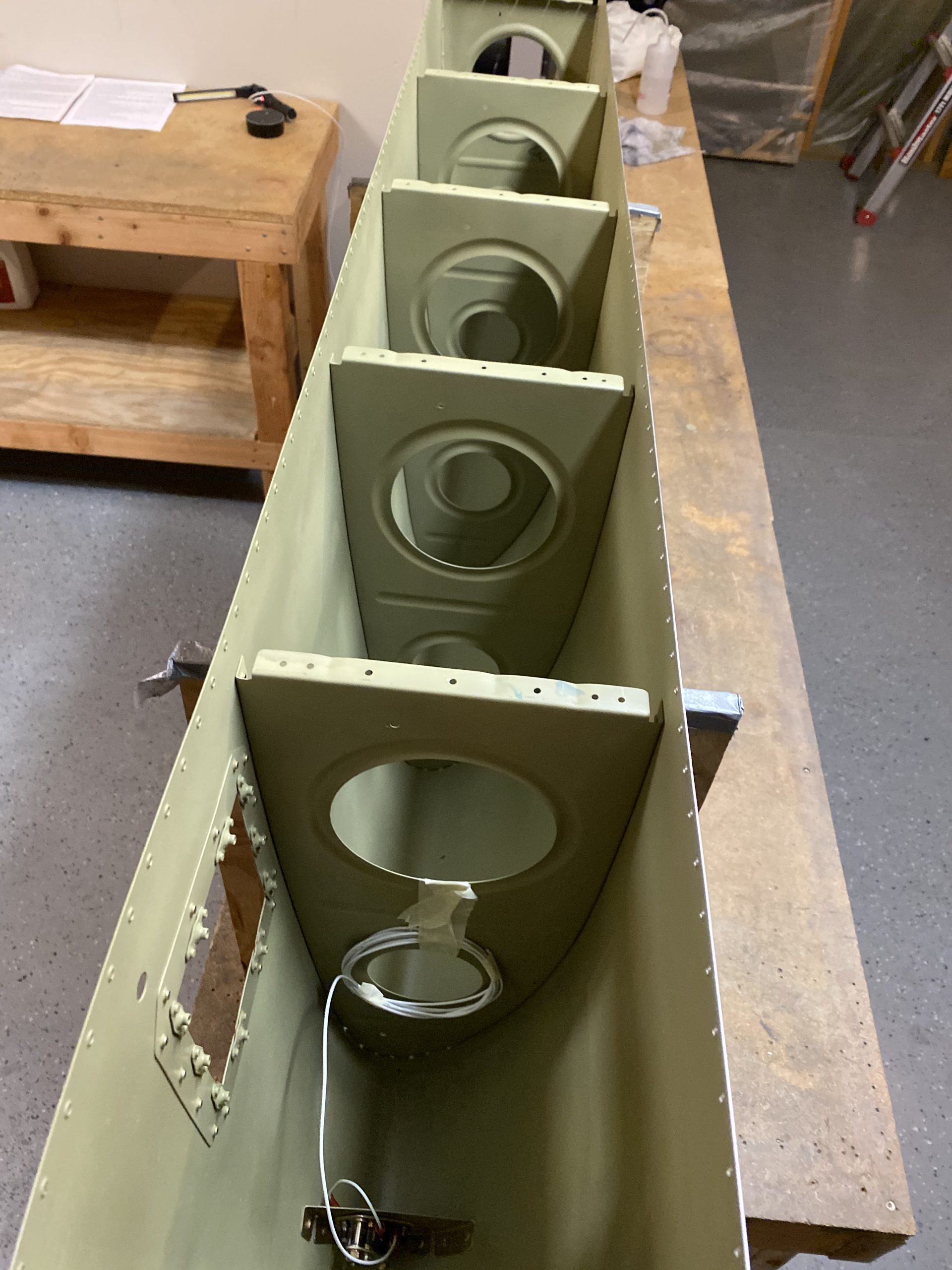
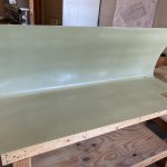
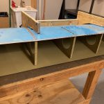
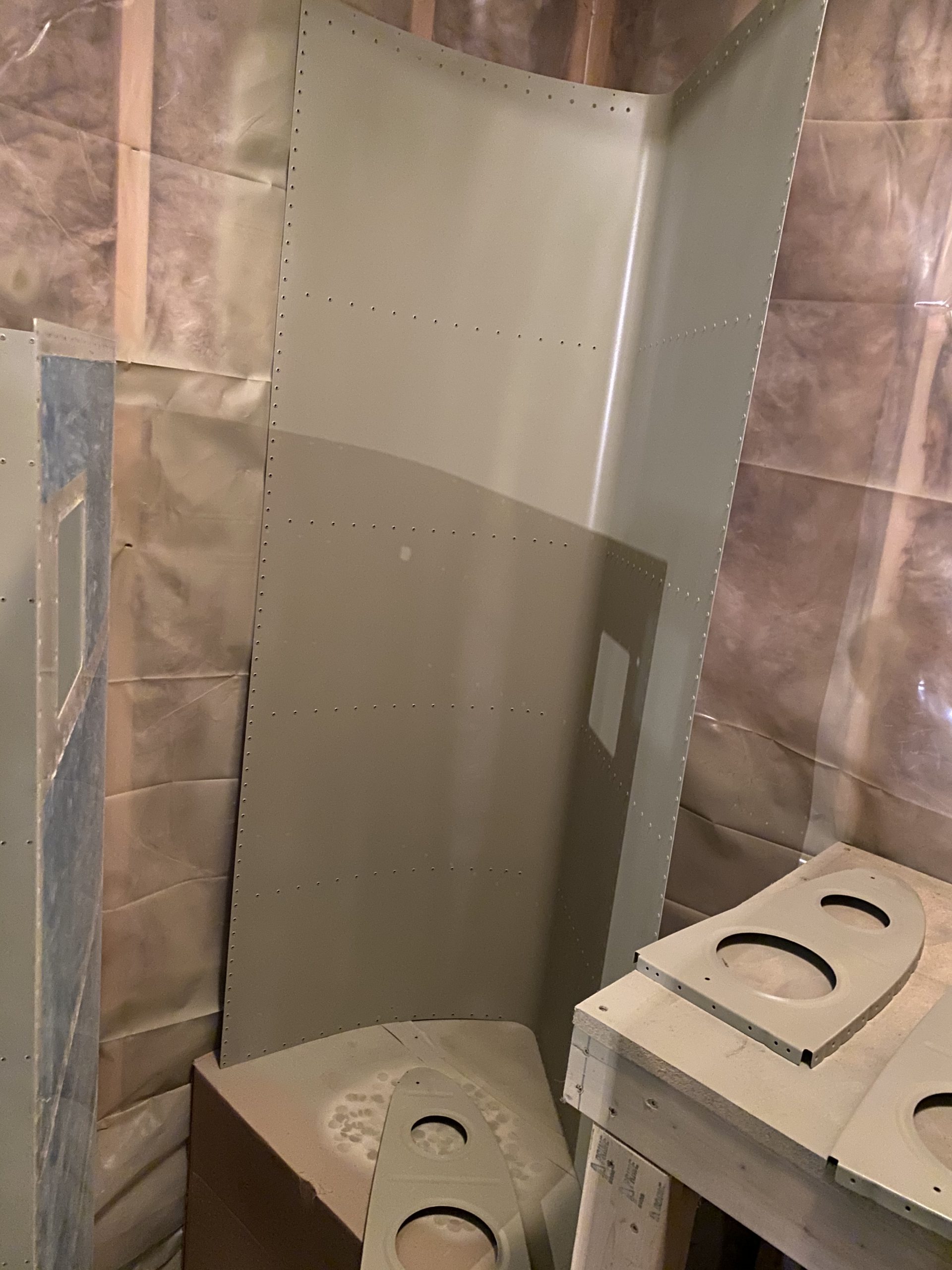
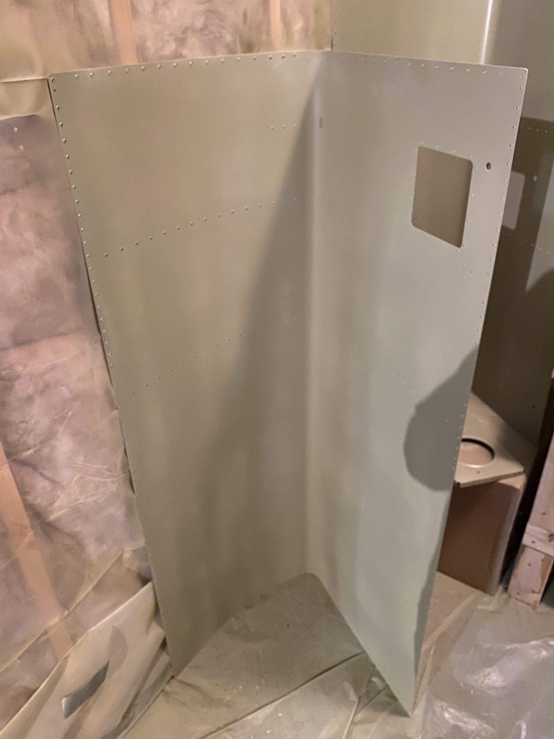
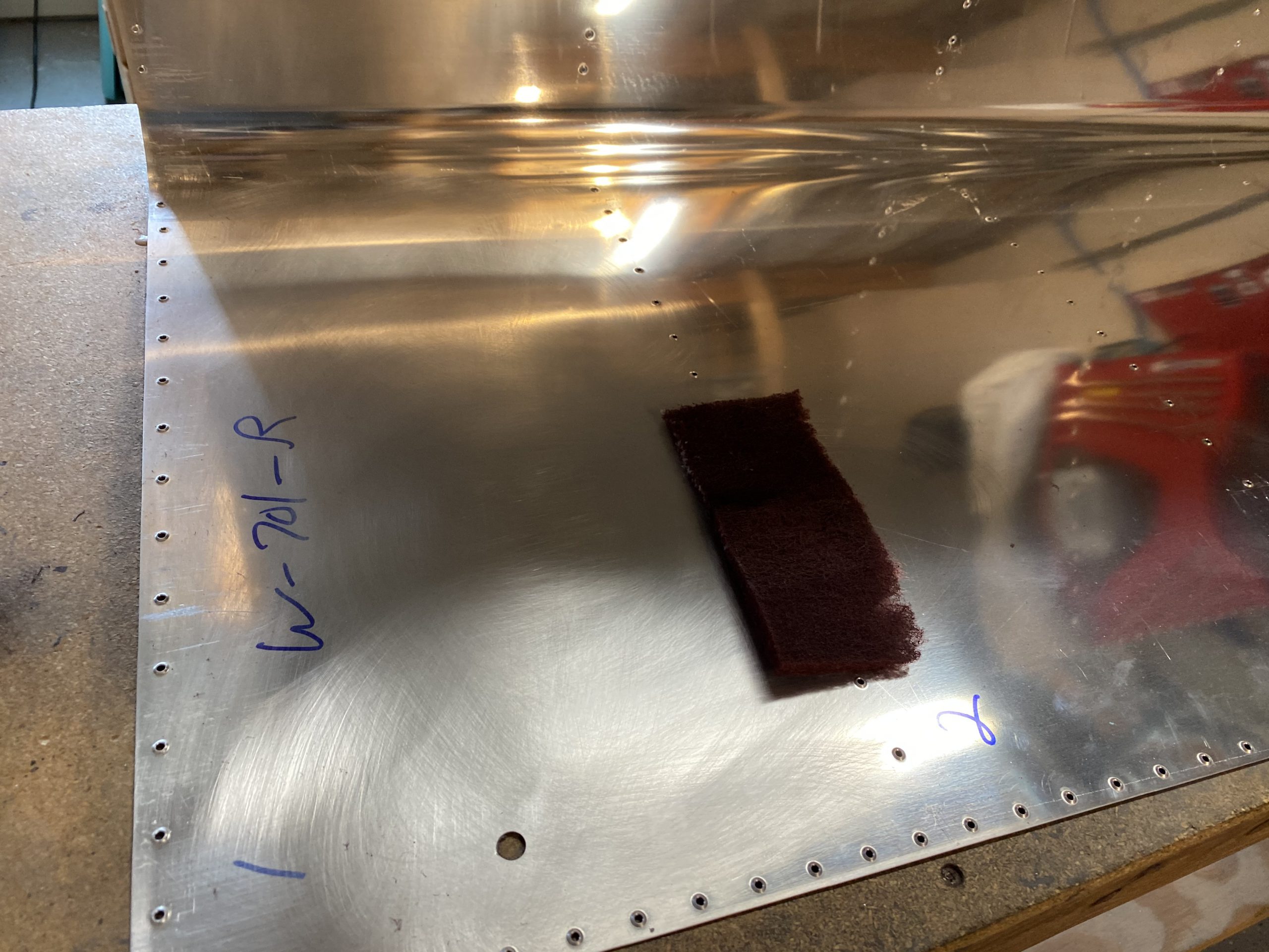
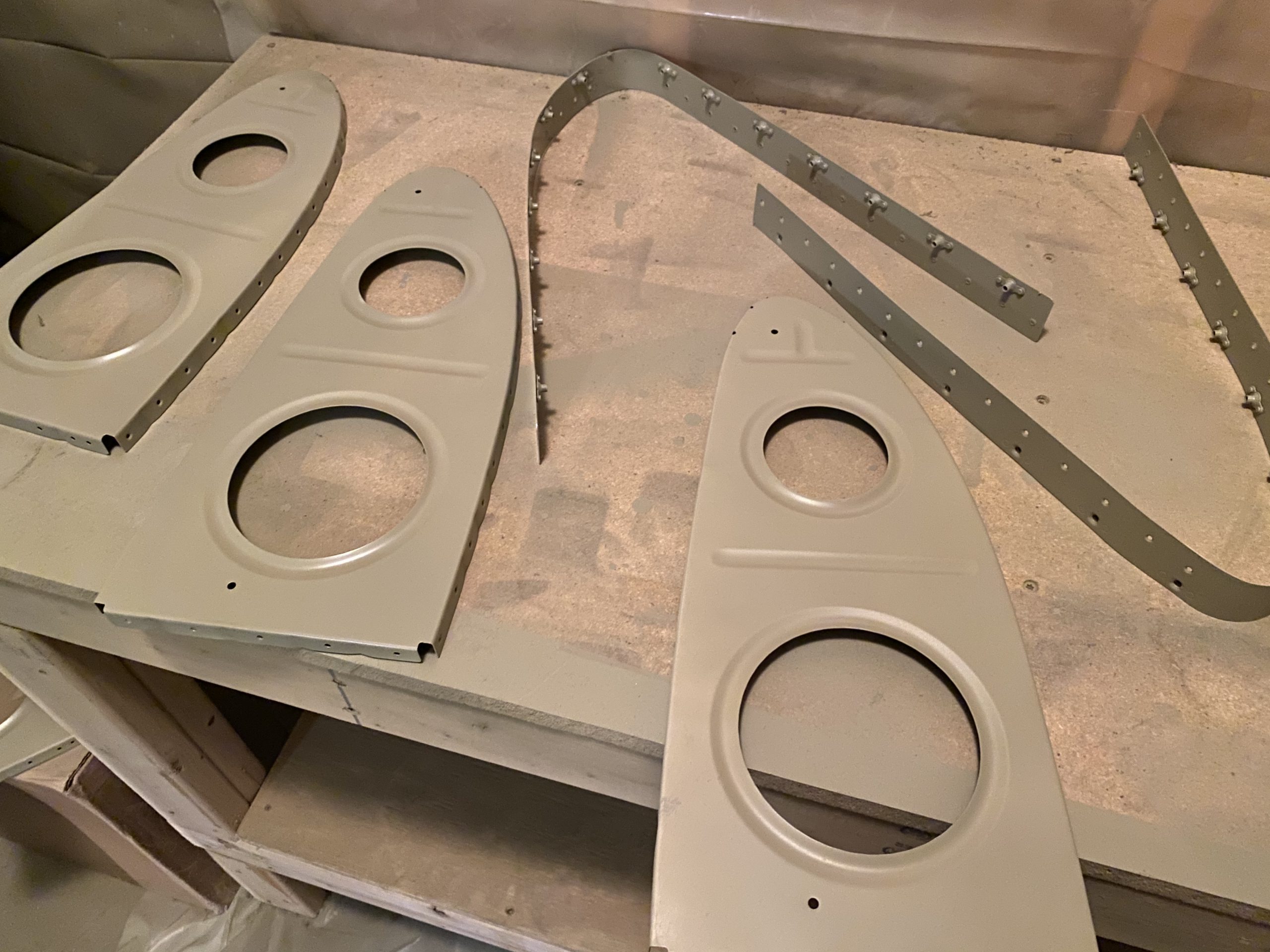
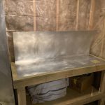
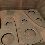
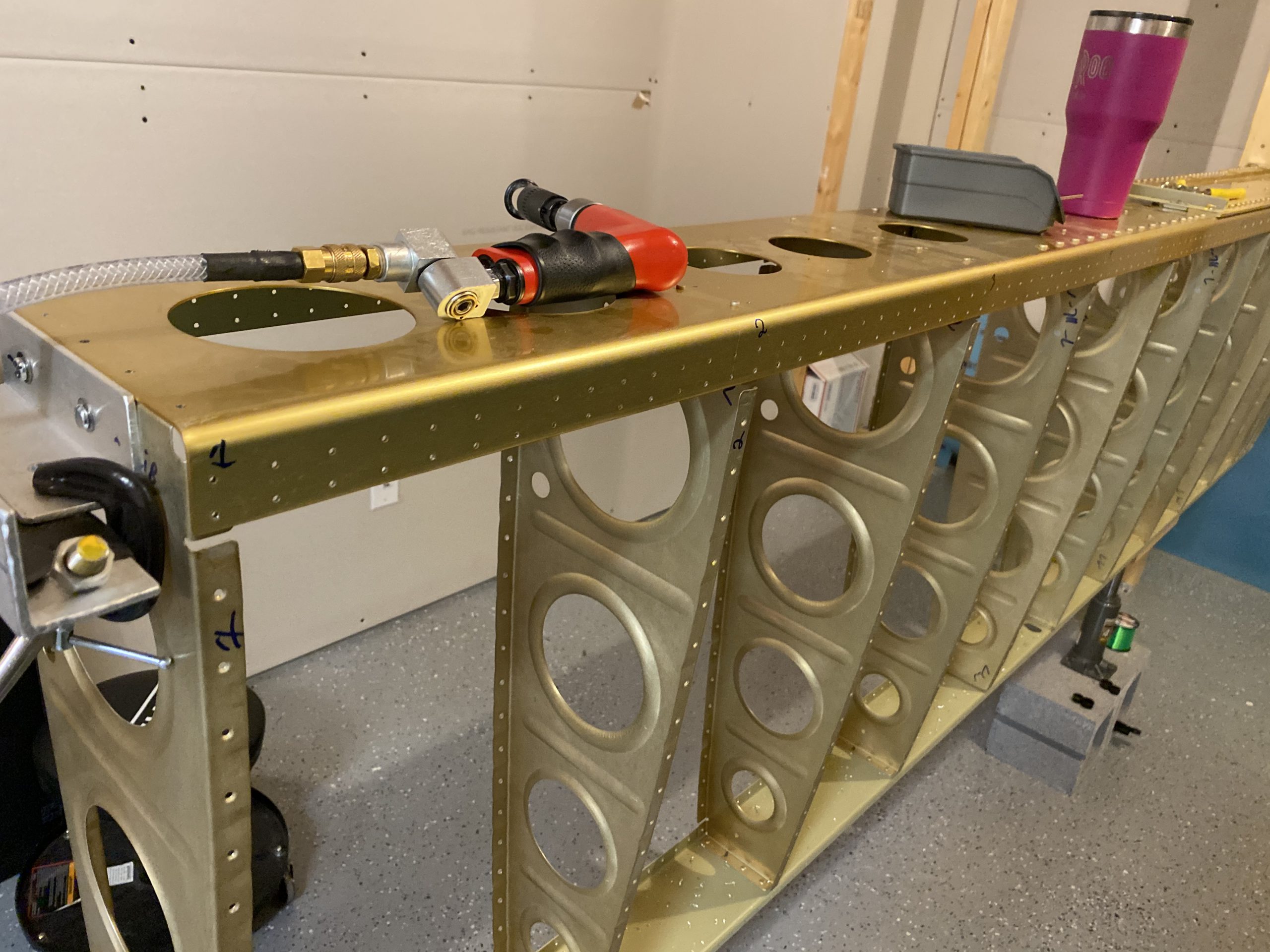
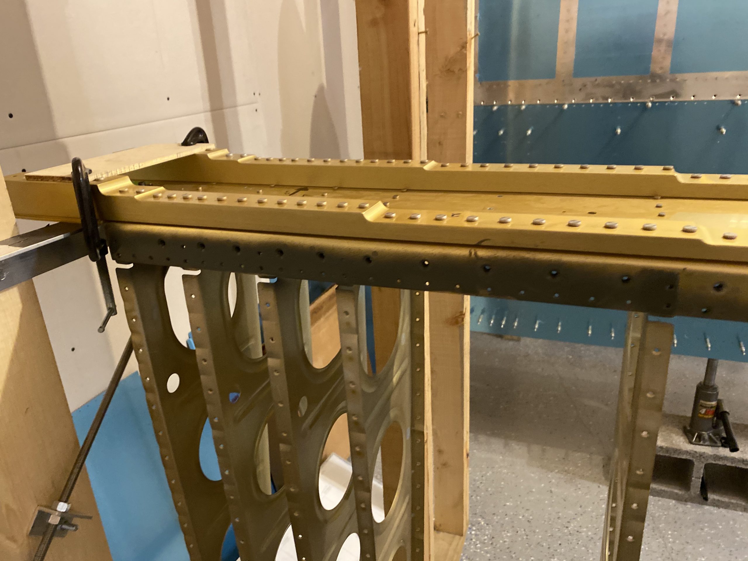
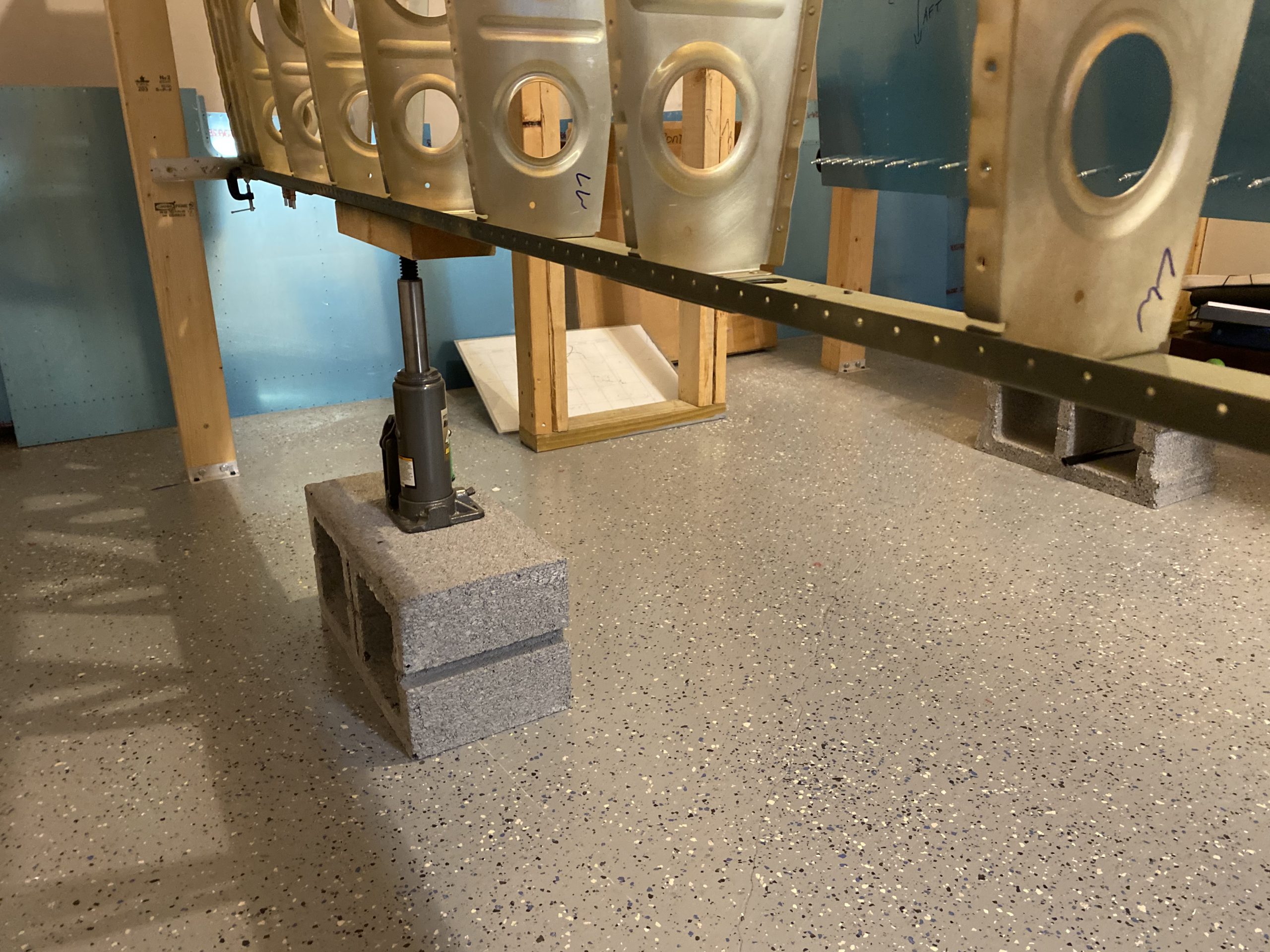
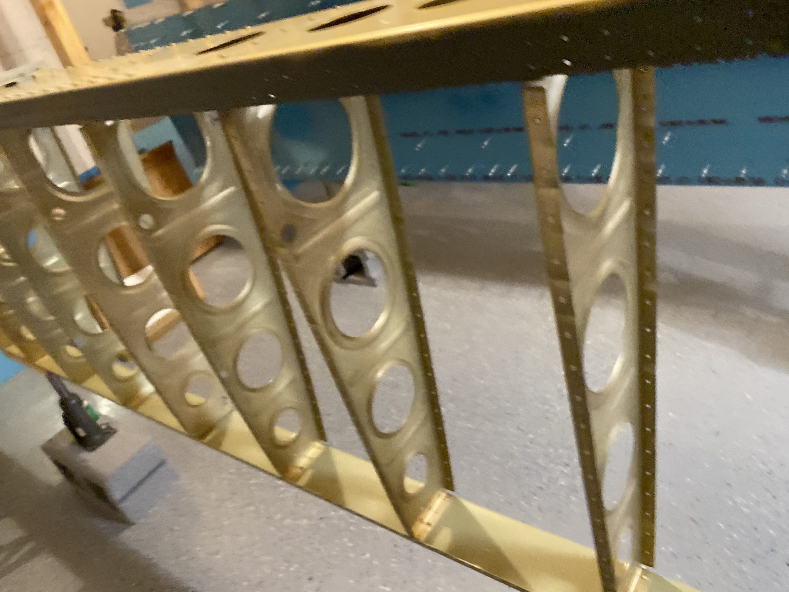
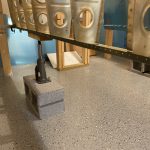
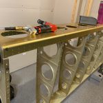
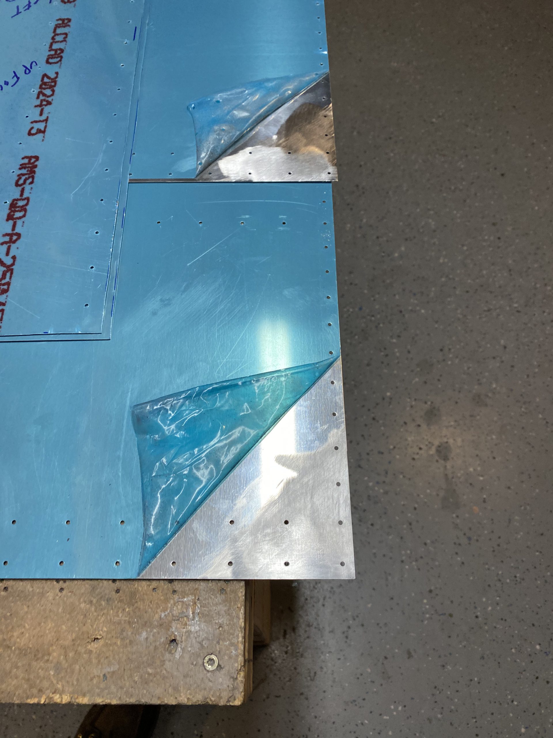
After that, I did a little cleanup, and pondered a bit while looking at the skeletons of both wings.  Thinking about the pitot mast, wiring, conduit, etc and sort of planning for it all.  These things are starting to take shape, and its feeling pretty good.  I’d love to get the top skins riveted on soon so that I can get them into the cradle for the rest of the work.  Like most every other builder, the bottom skins will remain off until right before mounting to the fueselage, this way I can decide on autopilot servos etc.  I did get the top skins up on the bench and done some more scarfing on them.  I am not 100% happy with these scarf joints.  I think I may borrow my wifes sander and try some emory cloth on it to see how it does on knocking these down a bit.  Here is what they look like so far:

Thats it for tonight.  I’ll keep plugging on these top wing skins for both wings next.  I’ll probably deburr them, break the lap joints a bit, then get them ready for scuffing and priming. Then I’ll dimple them and start riveting them on!

Google Photos Link: https://photos.app.goo.gl/mnMDQFZWGgtfeCta7

Hours Worked:  1.75

Riveting the Right Leading Edge and Attaching to Skeleton

ALOT accomplished in this session.  I managed to get the right leading edge fully riveted, AND even got it attached to the right wing skeleton with some help from Tammy. This wing is ready for the fuel tank to be attached, and then on to the top skins.  I managed to capture the entire work session in a time lapse below:

I started by using my squeezer to squeeze the aft 3 ritvets on both the top and bottom of the leading edge.  This worked pretty easy, I wish I could have squeezed all of them!

The rest I bucked old school.  Not a lot to talk about here, but I did manage to get all of the ribs riveted on completely.  I did use caution and make sure I used the slightly longer rivets on the inboard rib where the splice plate goes to attach the fuel tanks.  Since we have another piece of metal in this sandwhich, we need a slightly longer rivet.

I did get a little creative with affixing the cradle to my work table to make riveting it a bit easier.  I wound up using my clamps to hold each other down while also holding the leading edge cradle:

This actually worked better than I thought it would!  After a little bit of work, I had all the rivets set in the leading edge ribs.  I also went back and inspected each one to make sure I had them all set corretcly and there was a handfull that I needed to buck a few more taps.  I’m happy with all of them now.

I grabbed a timelapse of me just working on the leading edge, which I will share below.  Its a bit of a closer view than my normal overhead.

After this, it was time to rivet the leading edge onto the right wing! I double checked the twist and sag on my main spar with a digital level, and the fishing line strung across the rivet holes.  Then I vacuumed all the shavings and dust from the skeleton to get it squeeky clean for final riveting.  Then I sat the leading edge down onto the wing and clecoed it in place.

I got my wife Tammy to come down and hold the bucking bar while I set the rivets that hold the aft flanges of the leading edge to the main spar web.  This made this work much easier and quicker than me trying to reach in and do it all myself, like it was on the left wing. Then she was free to go, as all I had left at this point was to rivet the skin to the main spar web, using a squeezer. Making sure that where the skin and ribs riveted together with the spar web I used the longer rivets for the extra thickness.  The time lapse below captured this work close up.

Now, my leading edge was riveted onto the wing!  The next thing I did was to insert the rivets that hold the very forward section of the ribs to the main spar web, underneath the tank skins.  These were AN426AD4-5 rivets, and I used the squeezer to set them.

Then I sat the tank on the leading edge to see how things fit, and I noticed I’ll need to clear some sealant around the skin where it bolts to the splice plate on the leading edge.  I let this goop out a bit to far.  No biggie, I’ll use a phenolic scraper to scrape just enough back to get the clearance I need.  But, that gets the right wing in a good spot, and at the same progress as the left wing.  I’ll need to scuff and prime the wing skins, then dimple them. Then I can proceed with the rest of the work. We’re getting close to being done on these wings!

And thats a good stopping point for today.  LOTS of work in this session, and I feel like I got a bunch accomplished.  I think I will change gears and deburr, scuff and prime the top wing skins so they’ll be ready to dimple and then rivet on.  I have ordered my pitot mast mount from Stein Air, and I decided to go with a Gretz Mount.  I’ll do a session just installing the pitot mast as soon as it gets here, so I’ll leave the top skin off the left wing until then.  This is where the build starts to get fun!

Google Photos Link:

  • IMG_2472
    IMG_2472
  • IMG_2473
    IMG_2473
  • IMG_2474
    IMG_2474
  • IMG_2475
    IMG_2475
  • IMG_2476
    IMG_2476
  • IMG_2477
    IMG_2477
  • IMG_2478
    IMG_2478
  • IMG_2479
    IMG_2479
  • IMG_2480
    IMG_2480
  • IMG_2481
    IMG_2481
  • IMG_2482
    IMG_2482
  • IMG_2483
    IMG_2483
  • IMG_2484
    IMG_2484

Hours Worked: 4.0

Countersinking the Right Wing Skeleton

Another quick build session. I managed to get the entire right wing skeleton machine countersunk. Pretty simple work, I did have to match drill a few holes I missed somehow, but no biggie.


I also sprayed some rattle can primer on the newly countersunk holes.


Hours worked: 1.5

Dimpling Right Wing Skeleton

Quick Entry tonight. I’m getting the right wing up to the point where the left-wing is so that I can rivet the skin zone at about the same time. Here’s a time lapse video.

I managed to get the right wing skeleton fully dimpled and even managed to remove a little metal from the rear spar temples as per the instructions.

The time lapse above pretty much shows everything that I did and I didn’t take many photos this was a pretty simple build process. That’s it for this quick session I think I will countersink the main spar in the next session.

Hours Worked: 1.0


Right Wing Leading Edge Work

Time to admit a mistake I realized early today:  I forgot to connect the fuel sender wire on the left tank (rear baffle) before I bolted it down! Not a big deal, as I only used a few screws to hold it, and I can easily unscrew and unbolt it to fix.  If it was rivets, this would be a lot more work!  So I started out by removing the left fuel tank, and I was going to make up a short piece of wire for the connector, but I soon realized I didn’t have the right size terminal connection to make a good fit.  So, I will hold off on the left tank until I order some terminals.  I did make up a short pig tail that I will use to make the tank serviceable.  This little pigtail will attach to the fuel sender with a ring terminal, and then go through an existing hole in the main spar web so that it can be easily disconnected if I ever need to service the tank later on.

I’ll give more detail on that when I get some ring terminals and mount the fuel tank on perminantely.  In this process I also noticed another mistake:  I forgot to set the flush rivets that are underneath the tank skin, h0lding the forward hole of the main wing ribs!  Thank goodness I caught this now!  I went ahead and squeezed those few rivets while I was here.  Took about 10 minutes.

A better view:

Then I moved on to getting the right wing ready for the work to get it caught up with the left wing.  I pulled off all the right wing skins and set them aside for finishing.  Then I grabbed all the parts from the paint booth for the leading edge and wiped down the overspray dust with a rag.  Then I put the skin in the cradle so I could get the ribs clecoed.

I clecoed the ribs into place making sure I got them in the right spots, thanks to numbering them before priming.  Once I had all the ribs in place, I set the leading edge onto the wing main spar to make sure everything was lined up nicely.

Then the leading edge went back into the cradle so that I can start riveting on it.  That may be tomorrows work session. That or I’ll countersink all the holes and dimple the ribs for the right wing.  Not quite sure yet, depends on what I am feeling like doing tomorrow.  I am going to get an order placed for some 18 gauge and 20 gauge Tefzel wiring, an assortment of terminal connectors and other wiring goodies.  I’ll probably go ahead and order my pitot mast, I still need to decide on Dynon or Gretz mounts.  I will be needing to get it mounted in the left wing before I but the top skins on.

Google Photos Link:

  • IMG_2438
    IMG_2438
  • IMG_2439
    IMG_2439
  • IMG_2440
    IMG_2440
  • IMG_2441
    IMG_2441
  • IMG_2442
    IMG_2442
  • IMG_2443
    IMG_2443
  • IMG_2444
    IMG_2444
  • IMG_2445
    IMG_2445
  • IMG_2446
    IMG_2446
  • IMG_2447
    IMG_2447

Hours Worked: 1.75

Bolting the Left Fuel Tank

I wasn’t quite sure what category to put this work under at first, but I soon realized I spent ALOT of time on the fuel tank portion, so I’ll put it under there.  I needed to get the scarf joint done on the two wing skins where they overlap, but I also needed the fuel tank secured in order to judge how well the scarf joint fits at the skin overlap, fuel tank, and leading edge intersections. I did capture a timelapse, but it doesn’t show much of the tank attach work.  Here it is in any case.

I started out by clecoing the skins back on and marking out where I needed to scarf their overlap with a sharpie.  Then I put them on the bench and used a variety of tools to file down the skins.  From a dremel with a sanding disk (didn’t work to good since it wasn’t a disk for aluminum, and clogged up QUICK), to a bastard file, to emory cloth and scotchbrite.  What seemed to work best for me was the bastard file, followed by emory cloth and finished up with a scotchbrite pad and wheel to get it nice and smooth.  This was quite a bit of work, but I managed to get it done.  I even had a little helped come down and do some filing! She had her Elsa Princess dress on to work in of course! I got a quick video of her helping, and learing how to do a scarf joint:

This was just my initial test of the scarf joint, but to make sure I had it right, I needed to get the tank bolted on, at least the top edge, so I can check the scarf joint is flush.  Heres a photo of my helper, as well as the scarf joints we done so far. I went ahead and rounded off the corners here as well.  I still need to fully deburr the edges of these skins later on.

So I moved on to the tank.  The plans tells us to install the tanks, putting a screw in every other hole on, and then installing about half of the bolts for the Z-brackets.  So thats what I did.  I had read that smearing some Beoelube on the AN509-8r8  screw threads before inserting them to help them tighten easier into the nutplates, and also help against corrosion.  So I gave it a try and it worked great!  The screws went in very nicely, and I was able to get every other screw installed on the top side of the tank with zero issues.

The camera had some shadows on the edge of the skin, but its laying very nice and flush against the main spar flange and fit nice and snug.  I also am very happy with the fit between the tank edge and the leading edge at the splice plate.  Its a very nice and flush fit!  Now, I moved on to inserted the AN3-4A bolts and AN960-10L washers into the tank attach z-brackets.  I did about half on each tank bracket, and most of them threaded right in with no hassle.  I had a few that I had to use a center punch to jiggle the bracket from the screw hole to get it lined up, which I am attributing the Z-brackets shifting a little when they were pop riveted on the baffle.  At most there was about 1/16″ of an inch I had to jiggle on a couple.  now the inboard most bracket (the one where the bolts thread from the opposite as the rest of the brackets), was a PAIN IN THE BUTT!  For some reason it had moved about 3/32″ or so and the holes would not line up enough for me to get the bolts in.  It took a LOT of slow and gently tinkering with all sorts of prying tools to get it to line up.  It wasn’t that it was hard to move, but rather just very little room to work in this area.  Once I managed to get one of the bolts to thread in, it pulled the bracket into alignment, and the other two threaded in nicely.  BUT, because these are SOOO close to the web of the Z-bracket I could not use a socket, I had to use a wrench, which only had about a few degrees of room to move.  It took a lot of tedious wrenching every 5 degrees or so to get all three bolts tightened down properly.  Unfortunately, there is no way for me to use a torque wrench on these, so I had to use my ole “Calibrated Elbow”, and guess.  All of the other bolts I simply snugged up for now.  Here is the aftermath.

I think I will spray some primer in this area just to cover the scratches on the bolt heads and where the alodine was very lightly scratched from all my wrenching.  This way its nice and protected.  I am NOT looking forward to the day (hopefully it never comes) when I have to remove these fuel tanks.  This is where I decided to stop for the night.  I still need to torque all the other Z-bracket bolts down to spec, and mark them with torque seal, then install the screws on the bottom of the tank.  I’ll knock that out in the next session.

Google Photos Link: https://photos.app.goo.gl/JxtNLh1qq4GCjmbC7

  • IMG_2435
    IMG_2435
  • IMG_2427
    IMG_2427
  • IMG_2428
    IMG_2428
  • IMG_2430
    IMG_2430
  • IMG_2431
    IMG_2431
  • IMG_2432
    IMG_2432
  • IMG_2433
    IMG_2433
  • IMG_2434
    IMG_2434

Hours Worked: 2.25

Riveting the Leading Edge to the Left Main Spar

Wing is taking final shape! I was able to get the left wing leading edge completely riveted on to the main spar tonight, and its looking like a wing!  I also captured two time lapse videos, one closer view, and another overheard.  Here’s those videos:

And here is the overhead looking at the majority of the shop.  It gives a little more context as to what I am doing off screen.

I started out by removing the fully assembled leading edge from the cradle, and clecoing it onto the left main spar.  Then I tied my fishing line across the main spars front flange rivet holes so I could adjust the sag out of it because this it the point where things get riveted into their final position.  I realized I didn’t start the timelapse video, so I didn’t capture this part.  I will probably take a short video to explain how I use the fishing line when I do the right wing. I clecoed every other hole along the skins attach point to the spar flange, and then where the aft flange of its ribs attach to the spar web.

Then I started riveting.  I bucked all of the rivets on the aft flanges of the leading edge ribs to the main spar web using the AN470AD4-5 rivets called out in the plans first.  Further inboard, the spar web reinforcement plates add more thickness, so the plans steps up the rivet length to an AN470AD4-7 so take note.  These were the most challenging rivets to set to date.  The manufactured heads are VERY VERY close to the ribs, and you have to use an offset rivet set to get to them.  Even then, they are still very challenging to get centered in the rivet set.  Then, you have to reach inside the access holes with the bucking bar and sort of feel around until you find the rivet and hope you are setting the tail nice and straight.  I went slow and deliberate on these so I could get them right.  They will be very difficult to drill out.  Here is about the only photo I could snap of the rivet tails, from the very inboard rib.

Once those aft flanges were riveted, I moved on to riveting the skin to the main spar flange.  This was super easy because I had plenty of access by leaving the top and bottom wing skins off the skeleton.  I was able to get to them with my squeezer, which made very nice and perfect rivets.  I started out by riveting every other hole, EXCEPT the holes that had the wing ribs.  These wing ribs need a larger rivet, and a little more attention to make sure everything is straight.  So I left them till last.

Once I had that first set of every-other-holes, I removed the clecos, and then riveted the remaining holes, leaving the clecos in BOTH holes where the wing rib attaches to the main spar flange. As in this photo, you can see the two clecos in each wing rib:

Once I had all of the other holes riveted, I went back and removed the TOP cleco from the wing ribs, so that I could insert the slightly longer AN426 rivet in place, make sure the wing rib was lined up, then squeezed it.  I left the bottom cleco in to help hold the rib straight.  That hole is where the top skin will rivet later on.  These were also very easy to squeeze.  With that, the leading edge is riveted on!  I did a quick check with the fishing line to make sure the spar had zero sag, as the line passed through the middle of every rivet hole.

The last thing I did tonight was place the fuel tank onto the main spar and check its fitment with the splice plate on the leading edge.  It fit fairly decent, but not perfect.  I think its due to the tank sealant that squished out onto the tank skin edges keeping it from sitting flush on the splice plate.  I’ll work on this a little later, and its hopefully as simple as scraping away some of the excess squished out sealant.  But, everything does appear to line up.  You can see the small gaps in this photo

That ends the work for tonight.  I think I will work on the left wing top skins.  I need to get the scarfing done where the two skins overlap, then get them primed and ready for dimpling.  That will probably be a good work session for my next trip down to the shop.  Then I’ll repeat these same steps on the right wing.  It certainly feels like its getting close to being done!

Google Photos Link: https://photos.app.goo.gl/27U6PLgFbSMpZM217

  • IMG_2380
    IMG_2380
  • IMG_2381
    IMG_2381
  • IMG_2382
    IMG_2382
  • IMG_2383
    IMG_2383
  • IMG_2384
    IMG_2384
  • IMG_2385
    IMG_2385
  • IMG_2386
    IMG_2386
  • IMG_2387
    IMG_2387
  • IMG_2388
    IMG_2388
  • IMG_2389
    IMG_2389

Hours Worked: 2.25

Riveting the Left Wing Leading Edge

Man! Got a lot knocked out today! The left wing leading edge is completely riveted, and ready to be attached to the wing skeleton, including the stall warner.  I got a text from Tammy mid-build s her BMW overheated, and was low on coolant, so I had to pause and rescue her, dropping the car off at a mechanic.  Hopefully that bill won’t be too bad when they check it out Monday.  Here is the first part of the timelapse:

I pulled the left leading edge parts from the paint booth, as they are cured and ready for work.  Then I wiped them down with a shop towel to get rid of any overspray that may have landed on them.  After that, I put the leading edge back into the cradle, and started assembling it. Heres how nice the parts look!

After getting the skin in the cradle, I clecoed all the ribs into place, every other hole since its time to rivet them!  But first, I needed to get the doubler plate installed for the access panel for the stall warner.  I primed it and its ready to install.  I’ll leave the actual access plate off for now.

I clecoed it in place, and then used my squeezer to set these rivets nice and flush to the skin.  I did check that the cover plate fits nicely as well, but Its going back on the shelf until its ready to be closed up for good.  Probably a LONG way away.

With that done, its time to set all the rivets for the ribs.  You’ll see in the timelapse, that I carried the clecoed leading edge over to the wing, and placed it on the spar just to double check that all the ribs lined up correctly, and the holes for the aft flanges on the ribs lined up with the holes in the spar webs.  They looked good, so I went ahead and riveted all the ribs using by bucking them.  I also used some electrical tape to help hold the rivets in place, which worked pretty good (and cheaper than rivet tape!)

I left the inboard rib and splice plate off for now, as it made it a tad easier to reach in and rivet the tiny rib for the stall warner, and also made it easier to install the stall warner assembly.  Which was the next thing I did. About this time was when I got the text from Tammy needing me to help her with the overheating BMW.  So, I stopped the timelapse, and picked her and Acacia up.  Once I got home and settled after dinner, I came back down to finish this up.  I’ll leave this in one session, as it makes sense that way.  Just had a small break in between them.  Here is the second time lapse:

This is where I installed the stall warner assembly.  I got all the parts for it, and re-read the instructions and plans to make sure I remembered correctly.  In previous sessions, I had already assembled the warner assembly, I just needed to bolt it to the little rib, and adjust it, and hook up the wires.  Easy.

I made sure to get the adjustment per the plans, where it says to adjust the assembly so the minimal amount of movement from the vane causes the switch to engage.  I did that, and then tightened down the mounting screws.  Then I made up the 8.5 feet of 18 guage wire that snakes through the wing, crimped on the female spade, and connected it to the warner switch per the diagram.  I also fired up my Fluke to test that the switch went to ground as soon at it tripped.  I tested against the bare aluminum skin with one probe and the common lead from the switch with the other probe.  This is why I DID NOT spray primer on the little rib that mounts the warner assembly.  I wanted it to be a good conductor to ground via its rivets to the skin.  It is alodined, so it won’t corrode.

All that was left was to rivet the inboard end rib and splice plate to the leading edge, and its done!  This actually went a lot easier than I thought it would.  I recall the three (rib, skin, splice plate) being a PAIN to work with, but oddly enough, they clecoed together without much fuss. I fitted the leading edge to the wing spar, and then fitted the fuel tank to make sure it was all correct before riveting.  I bucked all of these rivets as well.

Thats it for this session. I cleaned up my work area, and then took a few photos of the final assembly.  Then I did a quick check of all the rivet shop heads using a rivet gauge to make sure they were all in good shape.  There was a few I decided to give a few more taps to set fully, and one hole I completely forgot to install a rivet in.  Easy to fix now, which is why I like to do a full inspection before mounting any skeletons like this.  Heres the final product!

Google Photos Link: https://photos.app.goo.gl/epnqtjC4fZLwe2Az5

  • 62042614636__811C2ABD-4CC5-4716-A072-7129EAB2749E
    62042614636__811C2ABD-4CC5-4716-A072-7129EAB2749E
  • 62042635052__5D1785B7-777B-42A1-9625-424EDCDE20DE
    62042635052__5D1785B7-777B-42A1-9625-424EDCDE20DE
  • IMG_2309
    IMG_2309
  • IMG_2310
    IMG_2310
  • IMG_2311
    IMG_2311
  • IMG_2312
    IMG_2312
  • IMG_2313
    IMG_2313
  • IMG_2314
    IMG_2314
  • IMG_2316
    IMG_2316
  • IMG_2317
    IMG_2317
  • IMG_2318
    IMG_2318
  • IMG_2319
    IMG_2319
  • IMG_2320
    IMG_2320
  • IMG_2321
    IMG_2321
  • IMG_2322
    IMG_2322
  • IMG_2323
    IMG_2323
  • IMG_2324
    IMG_2324
  • IMG_2325
    IMG_2325

Hours Worked: 3.75

Priming the Leading Edge Parts

Time to prime!  I was able to completely prime all of the leading edge parts for both wings in this session, including the access cover and plate for the stall horn.  I also realize my AKZO is past its shelf life, but it seemed to spray just fine and I think it will cure OK as well.  This will be a good test I guess.  Recall from some past posts, that the leading edge ribs were alumapreped and alodined WAAAYYYY back.  If you also recall, the two outboard ribs on the leading edge I had to re-order and re-drill because I wasn’t happy with the edge distance on those holes, so these new ribs were not alodined.  Same goes for the splice plates.  So, I’ll do them the old fashioned way.  Here is the timelapse for this session:

Notice a few things in that video:

  1. I am using the orange vent tube connected to a blower / ventilator thats outside to help vent some of the acetone and MEK fumes.  This worked pretty good!
  2. Towards the end of my spraying session, you’ll see some overspray coming from the top of my spray booth.  I noticed the makeshift airfilter I am using on the booth clogged up, reducing the negative pressure from the blower.  I’ll change this before the next session!
  3. Theres some time where I am sitting, waiting on the AKZO to kick-off.  It has a 30 minute induction time after mixing, before spraying.

The first step was to get my skins scuffed up good for the primer.  I used scotchbrite pads and elbow grease to get them all scuffed up.  I also realize I made a decision a long time ago to prime THEN dimple. I forgot to do that this time, so the dimples were chewing up my scotchbrite pads.  I’ll remember next time! I scuffed up both skins.

The bottom pic is the shiny “before” scuffing pic.  The top is after scuffing.  Then I moved on to do the same to the splice plates and end ribs, since they were not alodined.  These went pretty quick since theres only 4 total pieces to scuff.  After I had all my parts scuffed, I cleaned them very good, starting with MEK soaked paper towels, followed by another clean paper towel soaked with acetone.  These need to be very clean for good adhesion.  Once I got all the parts clean, I set them up in my booth.  For the parts that were alodined a while back, I simply had to wipe them down with acetone, no scuffing needed.  The acetone cleaned away any finger oils and dust that may have accumulated on them since they were alodined.  Easy to knock them out quickly. I did the same acetone cleaning for the access plate and reinforcement ring since they were also alodined.

Next was to mix up some AKZO.  I mixed up 10 ounces of the stuff, and let it sit for the 30 minute induction time.  I noticed my AKZO is now out of date by a year or so :-/.  Oh well, I will shoot it anyways and see what happens.  10 ounces was a good amount, as I had plenty left over to go back over the parts for a second coat to really offer protection.  It also gave me plenty of extra to work with on the touch ups.

After the induction, I suited up in my tyvek suit, full face respirator and got to work spraying the parts.  The old cheap Harbor Freight spray gun is still doing GREAT!  Well worth the 10 bucks I paid for it years ago. Spraying goes pretty quickly, and all leading edge parts were completely done in no time.  I REALLY need to change out the air filter in the spray booth, as its getting clogged with overspray, and not letting enough negative pressure in my booth.  The parts look pretty good so far:

The lighting in the spray booth isn’t great, and its hard to tell the coverage with all the shadows, and my camera doesn’t play nice with it.  But, so far they look pretty good.  Good enough to prevent corrosion and thats all I care about since these parts are internal, and will rarely ever get seen.  I’ll let them cure for a day or so, and then start assembling the leading edge! After I was done, I cleaned up my gun and shop and called it a night.  This cleanup was SOOOO much easier than the fuel tank sealant cleanup.

Google Photos Link: https://photos.app.goo.gl/L38fLuQkVwM12NKb6

  • IMG_2292
    IMG_2292
  • IMG_2293
    IMG_2293
  • IMG_2294
    IMG_2294
  • IMG_2295
    IMG_2295
  • IMG_2296
    IMG_2296
  • IMG_2297
    IMG_2297
  • IMG_2298
    IMG_2298
  • IMG_2299
    IMG_2299
  • IMG_2300
    IMG_2300
  • IMG_2301
    IMG_2301
  • IMG_2302
    IMG_2302
  • IMG_2303
    IMG_2303
  • IMG_2304
    IMG_2304

Hours Worked: 2.75


Countersinking Left Wing Skeleton

I forgone priming tonight, I’ll do that this weekend.  But, I did get some good progress on the left wing skeleton.  I completed all of the machine countersinking on the main spar, so its ready for skins!  Here’s the timelapse:

I chucked up my microstop countersink cage in my Sioux drill, and made a few test runs in the middle of the spar to be safe, and get make sure the countersink was still set correctly, and it was.  I verified by sticking a rivet in the countersink to make sure it was nice and flush.  Then I simply worked my way down the entire main spare, countersinking the holes for the leading edge skin, and the holes for the main wing skins.

Once I had all the holes countersunk, I needed to prime the now naked holes to prevent this exposed aluminum from corrosion.  I mocked up a cardboard template to keep the overspray off the pretty gold anodizing of the main spar, and sprayed some rattle can self-etching primer, doing my best to only get it in the holes.

I wanted to keep this layer pretty thin so as to not interfere with a nice smooth fit on the skin.  I think the holes are nice and covered in a protective layer now.  I also did the same on the rear spar, since I used a deburring bit to remove a small bit of metal in those dimples (per Vans instructions), and they also needed protection.

After that, it was time to clean up all the shavings, dust and debris that had collected in on the spars from sitting in the stands so long.  I grabbed the vacuum and gave the left wing a good cleaning.  It’s ready for its skins to be riveted on at this point.  I am planning on shooting primer on both leading edges this weekend, and I’ll jump over to getting both of them riveted, then do this same dimpling and countersinking work on the right wing.  This should help change up the work a little to keep it interesting.

Google Photos Link: https://photos.app.goo.gl/Z61nZUyTcHrJ1WWE8

  • IMG_2290
    IMG_2290
  • IMG_2289
    IMG_2289
  • IMG_2288
    IMG_2288
  • IMG_2286
    IMG_2286
  • IMG_2287
    IMG_2287
  • IMG_2285
    IMG_2285
  • IMG_2284
    IMG_2284
  • IMG_2283
    IMG_2283
  • IMG_2282
    IMG_2282
  • IMG_2280
    IMG_2280
  • IMG_2281
    IMG_2281

Hours Worked: 1.50