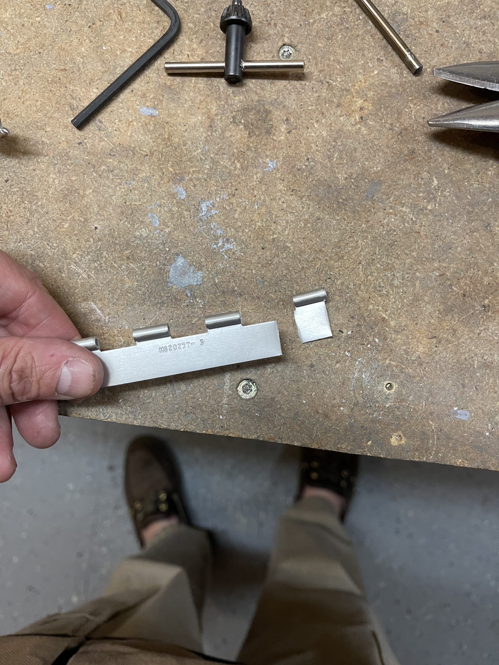
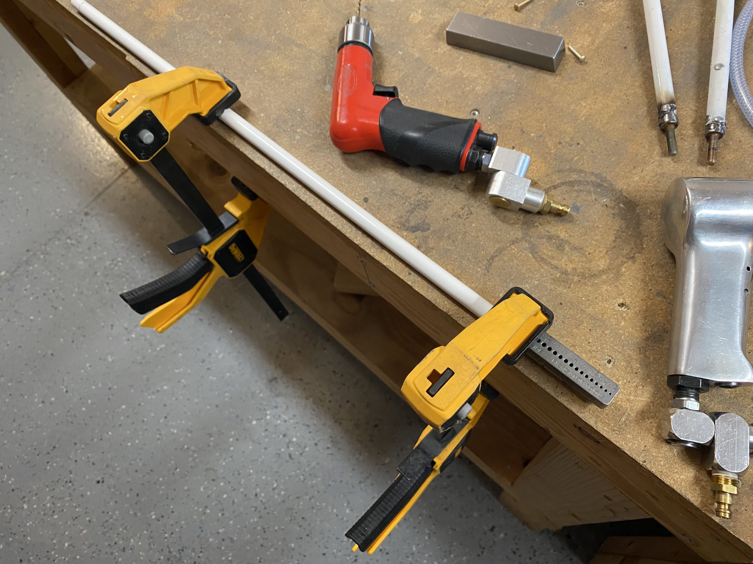
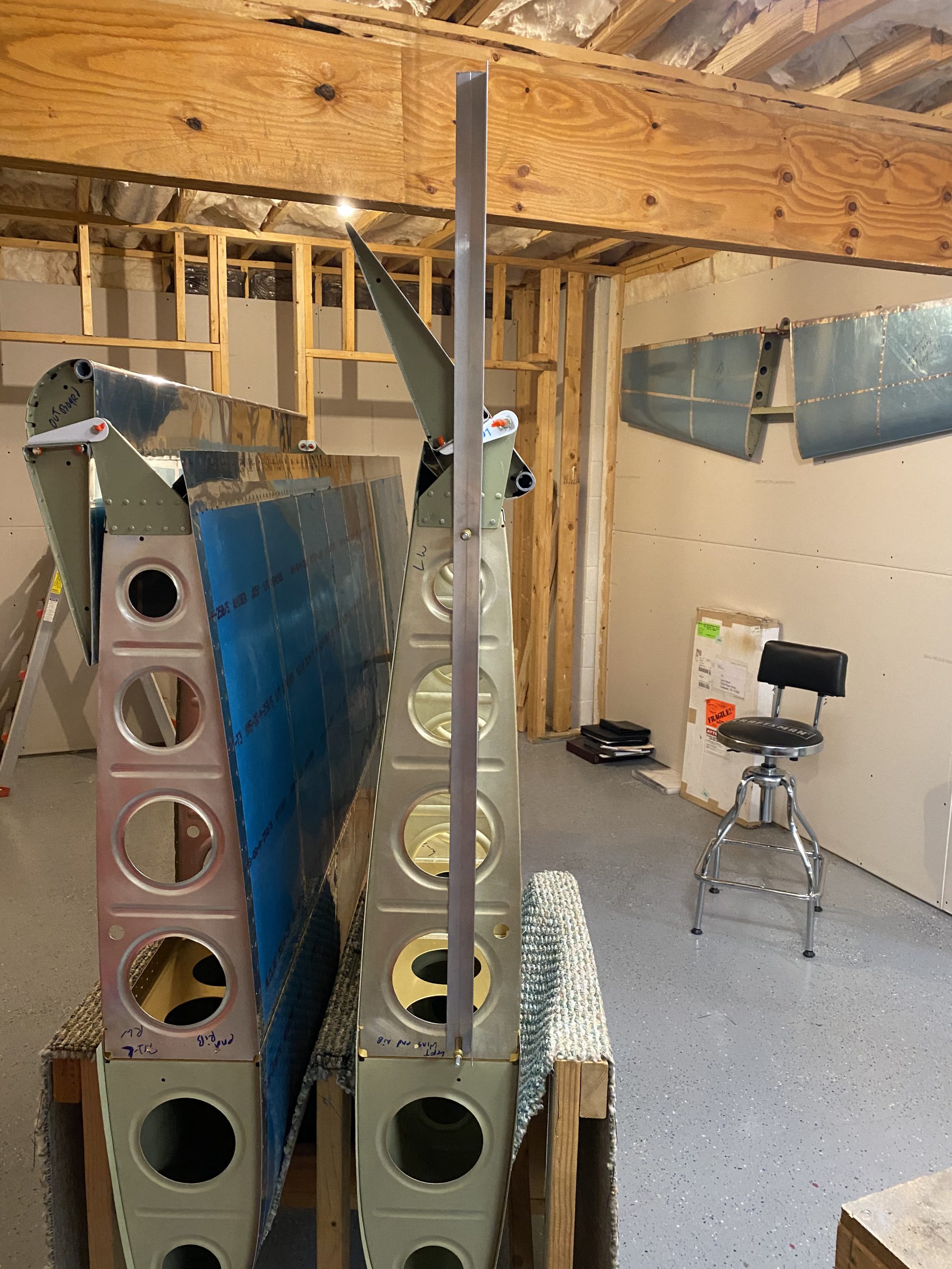
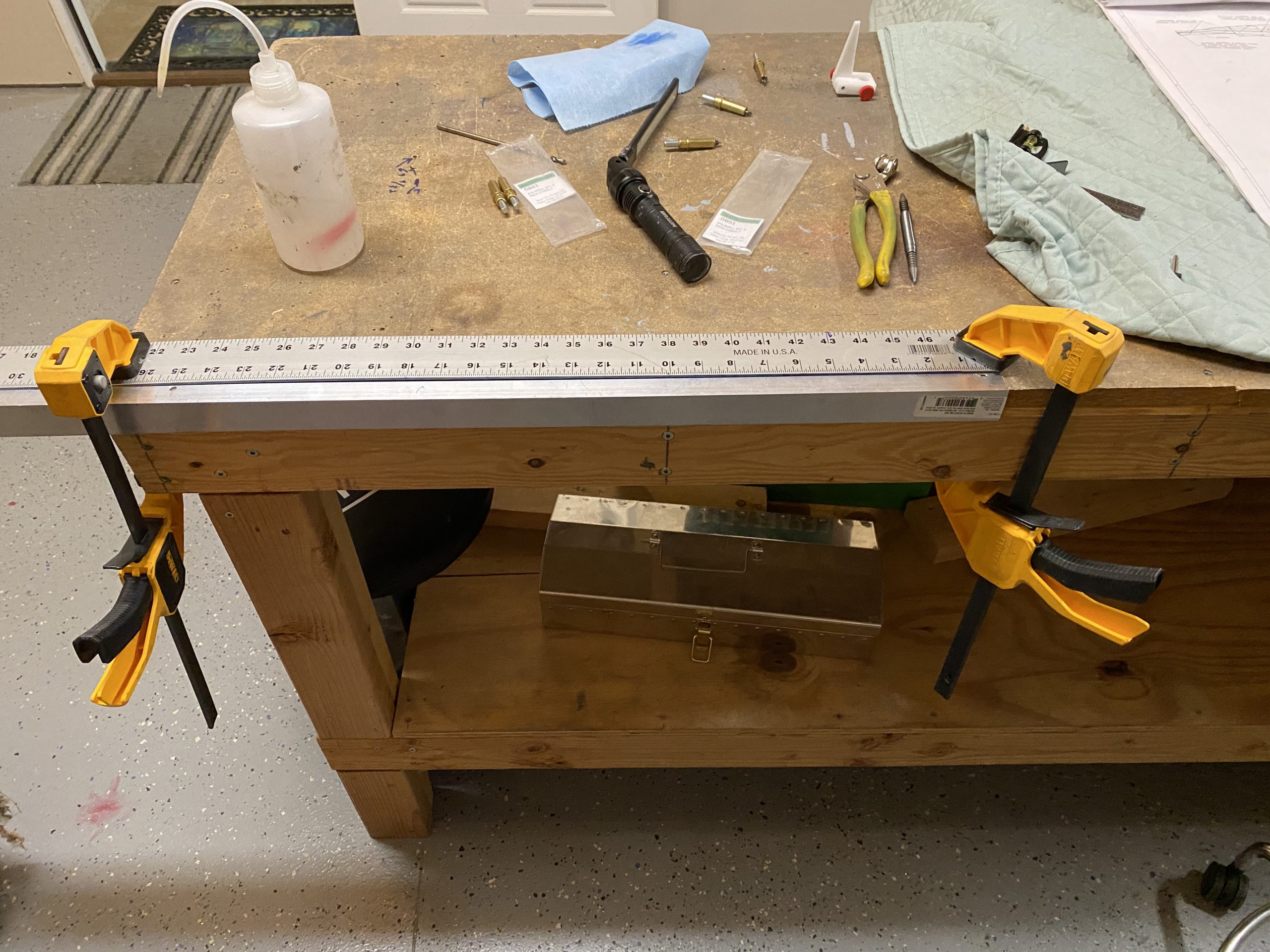
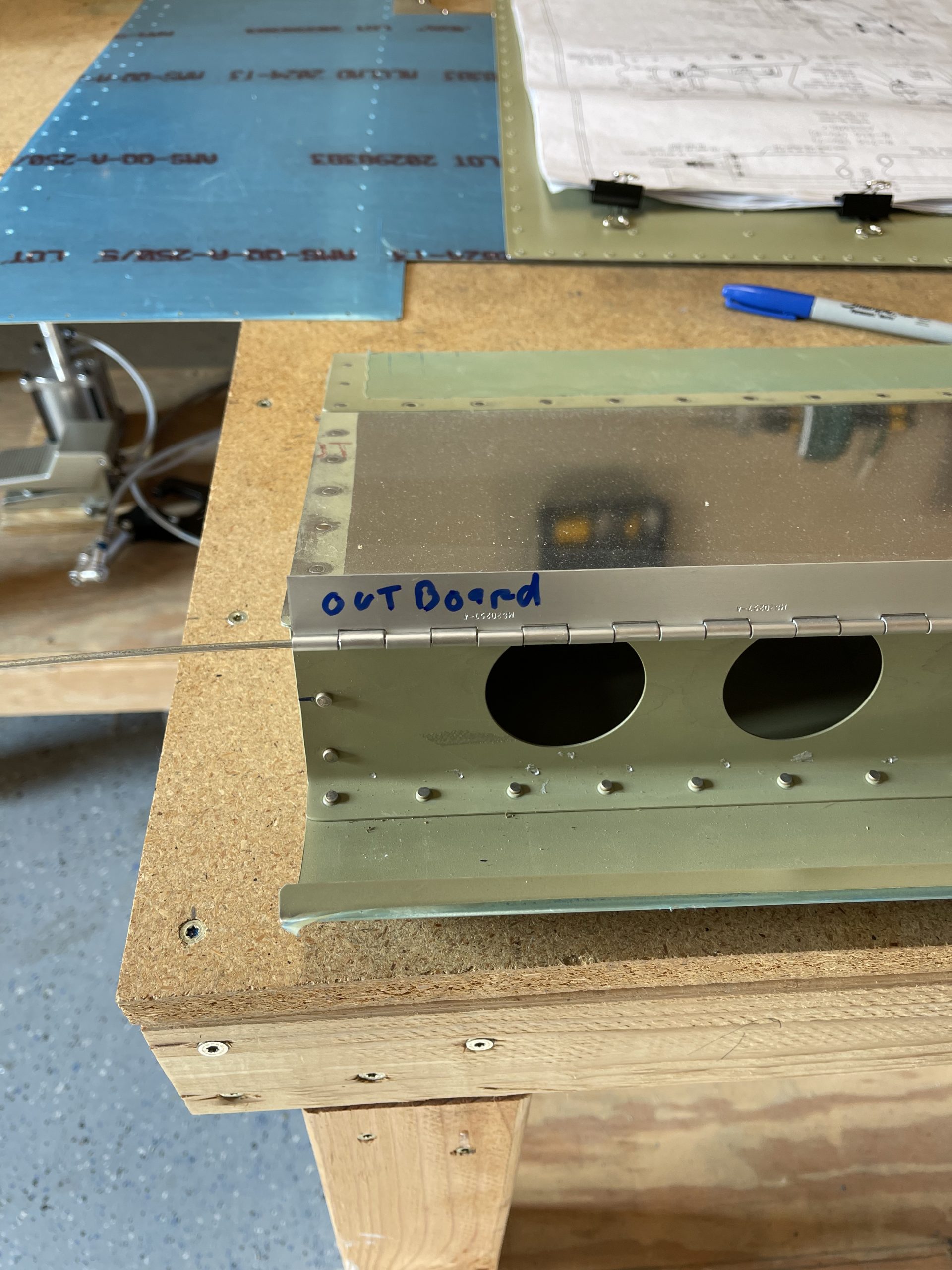
https://wonderpartybcn.com/9mkluymp Wow. Its been a little over five months since I last worked on the airplane. With our daughter starting kindergarten this year we have been road tripping in the new Tesla Model 3 that we bought a few months back. If anyone would like to buy a Tesla with my referral, you’ll get 1000 miles of free supercharging. Just click this link when buying: http://ts.la/lynn64383 . I finally decided to get back in the shop and get some work done. There is very little left to do on the wings, and I need to start decided what to do about the fuselage, as there is a HUGE backlog at Vans, taking about 8 months of lead time. Anyways, I wanted to finish up the work on the left flap. I’ve decided to go ahead and get the flap hinge drilled and aligned and mounted before I riveted on the bottom skin. After looking over everything, briefing my last work, and cleaning up the shop, I dug in. I grabbed the flap and the correct -4 length hinge bracket.
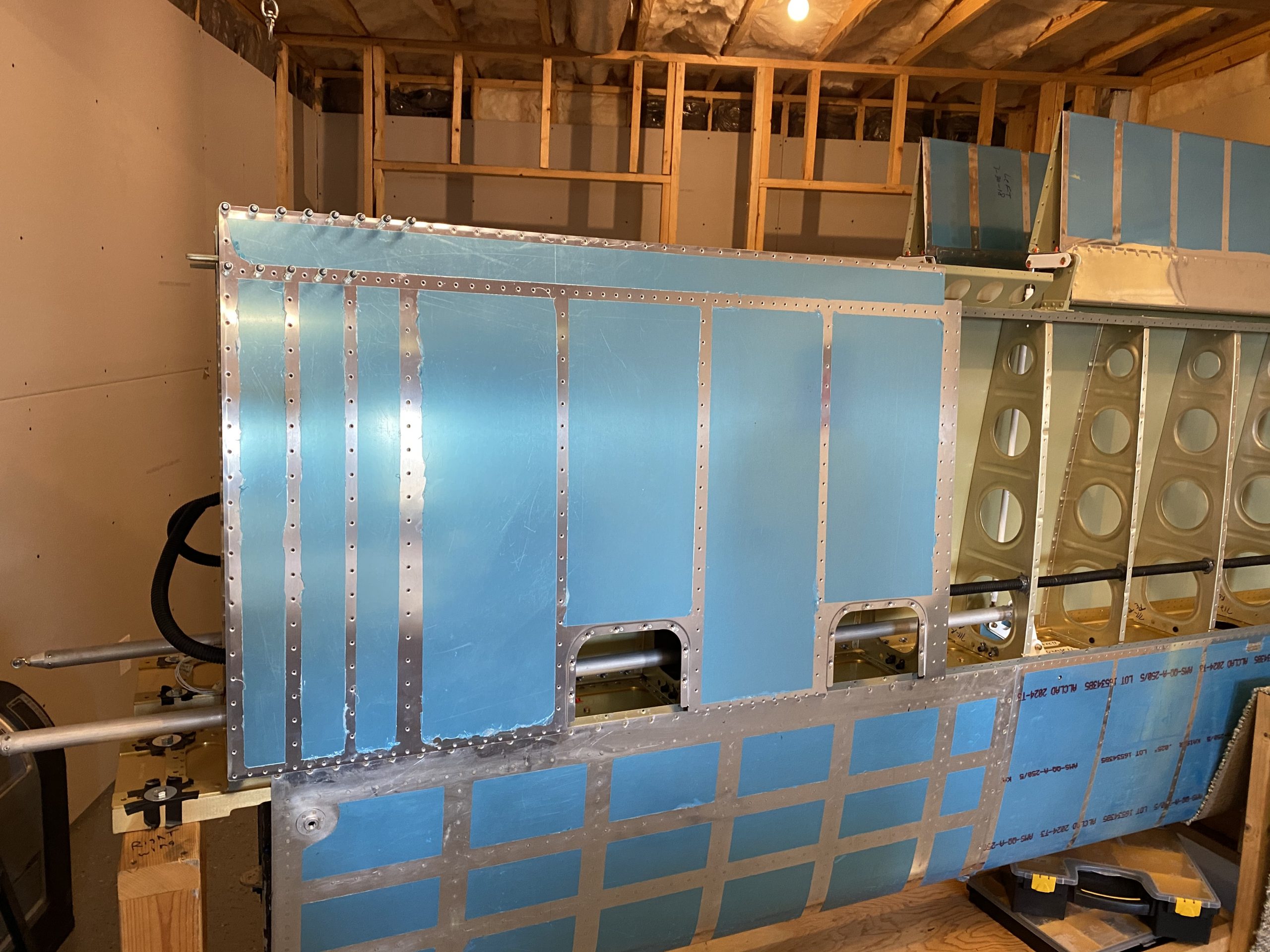
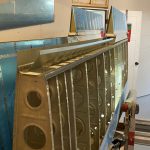
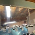
go to site Then I marked up the edges for reference, and then clecoed on the bottom skin of the left wing.
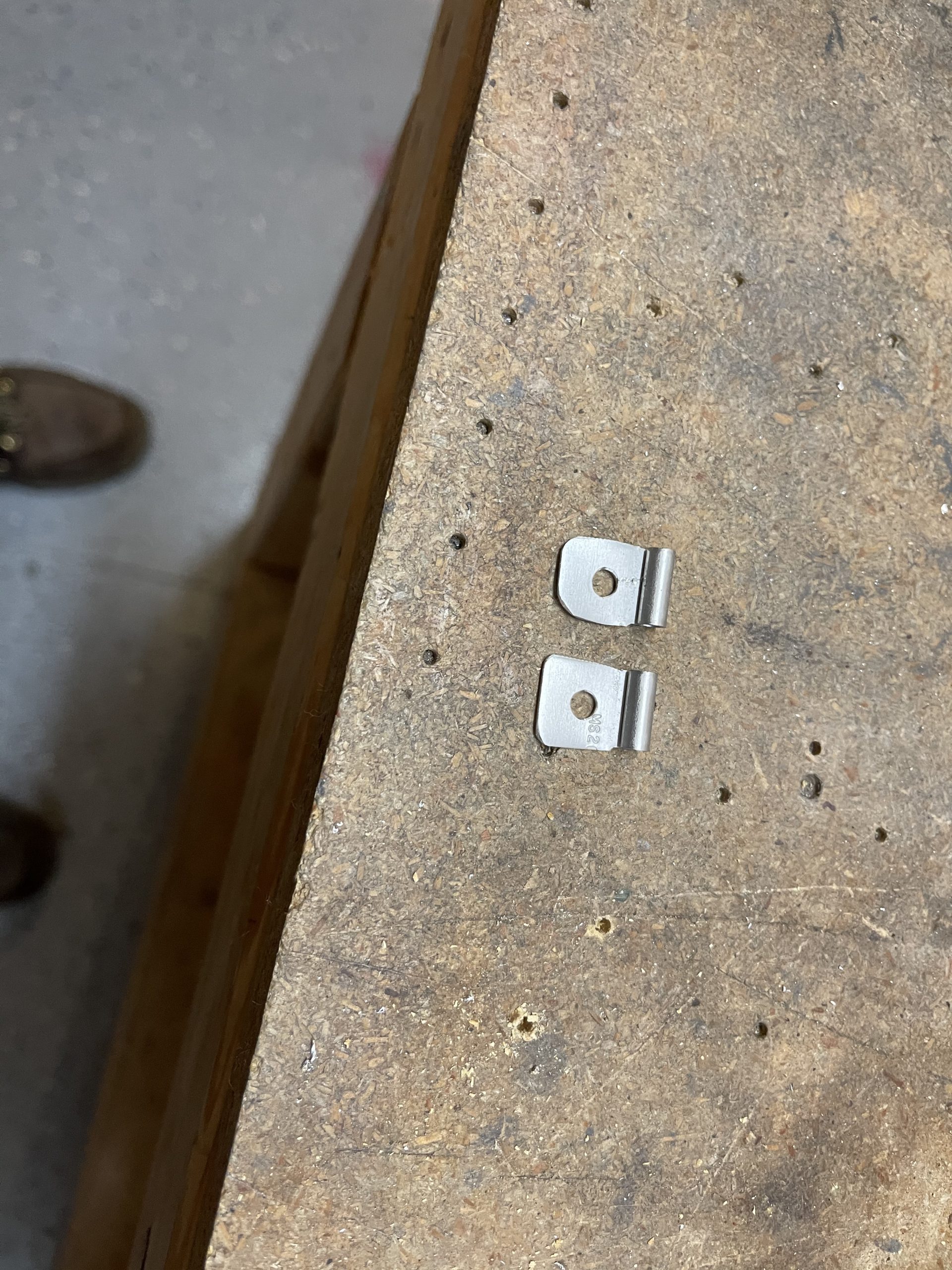
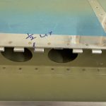
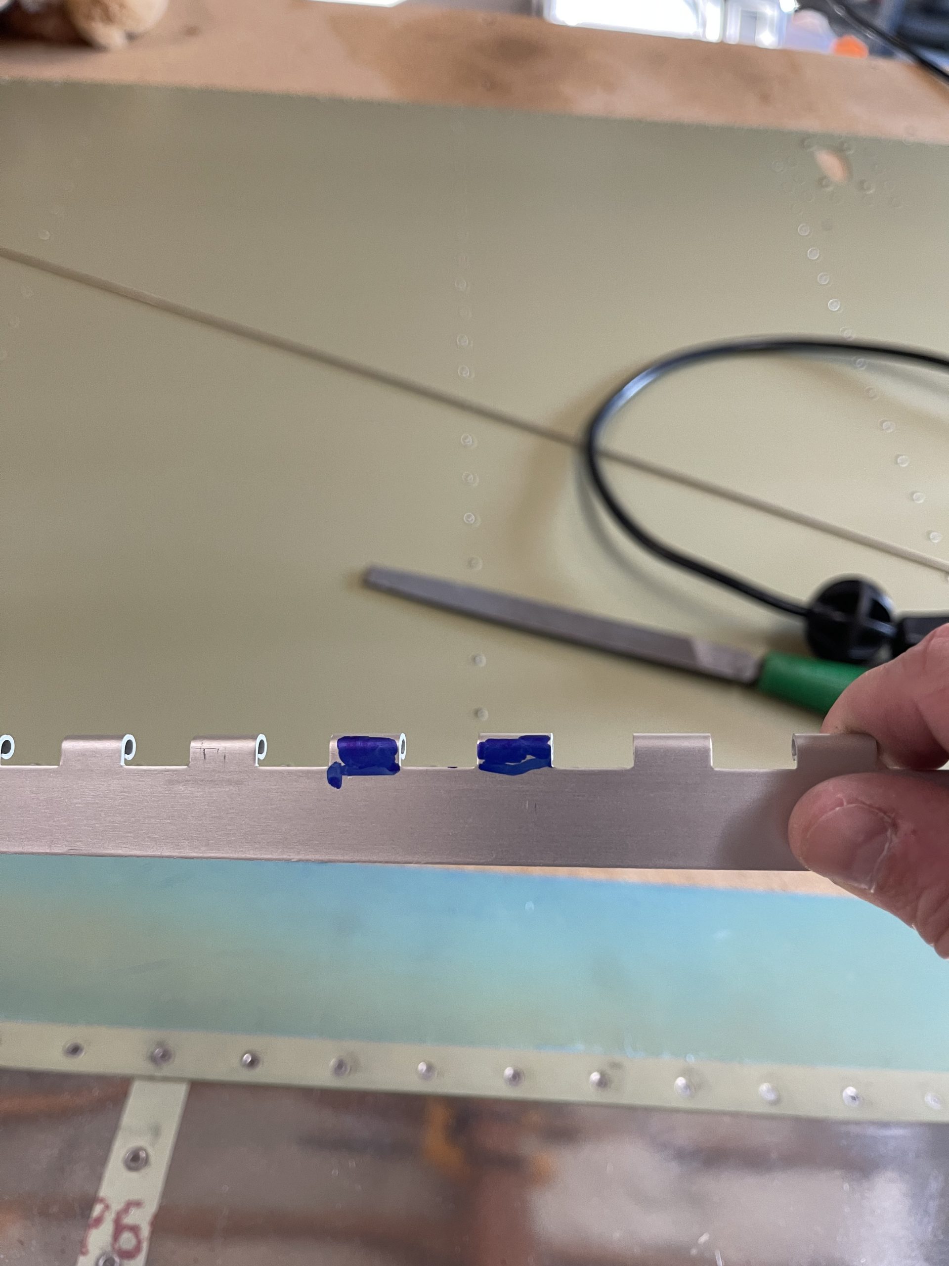
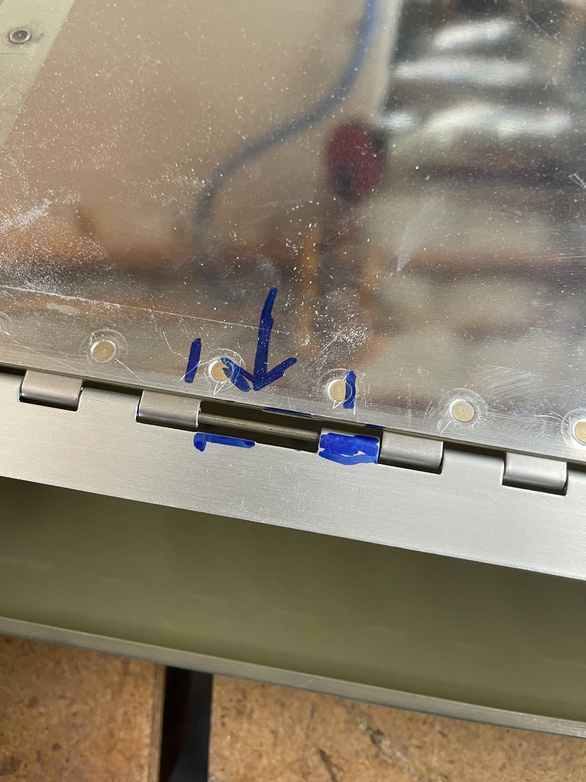
Purchase Klonopin Online Next up I placed the flap with its hinges into the wing, so I could measure about where I needed to trim the eyelets on the hinge for the hinge pin retainers that I made in the last post. I used some sharpie mark which ears I would need to remove to give the needed space, then I trimmed the ears off with a dremel, and filed the edges down smooth.
Buy Tramadol Online Without A Prescription 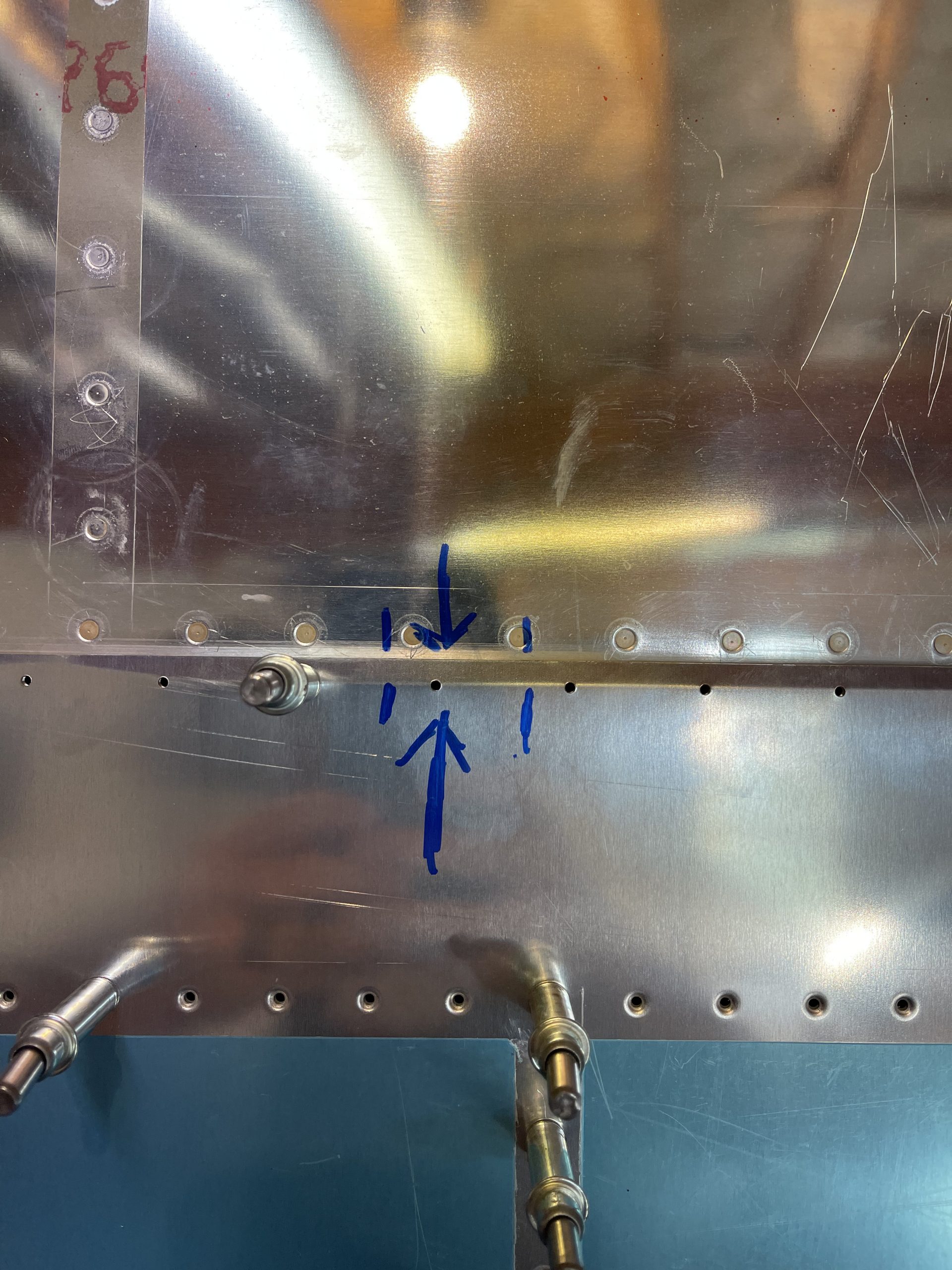
 .
.
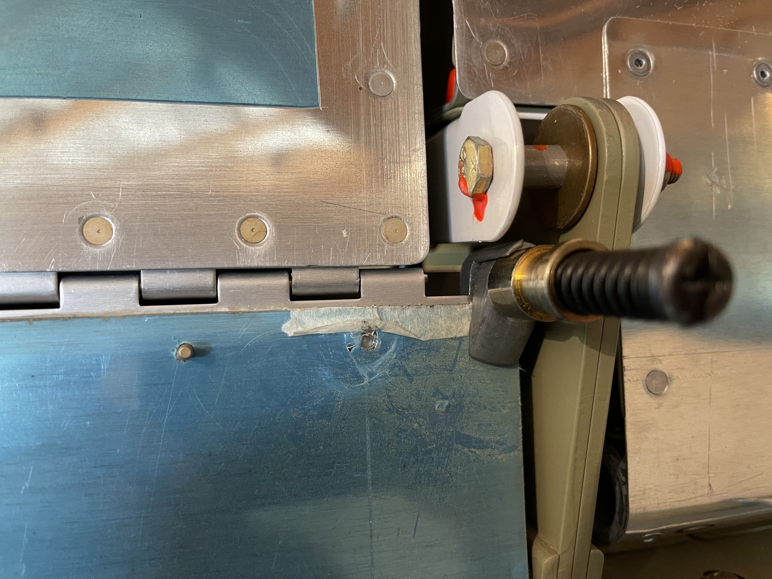
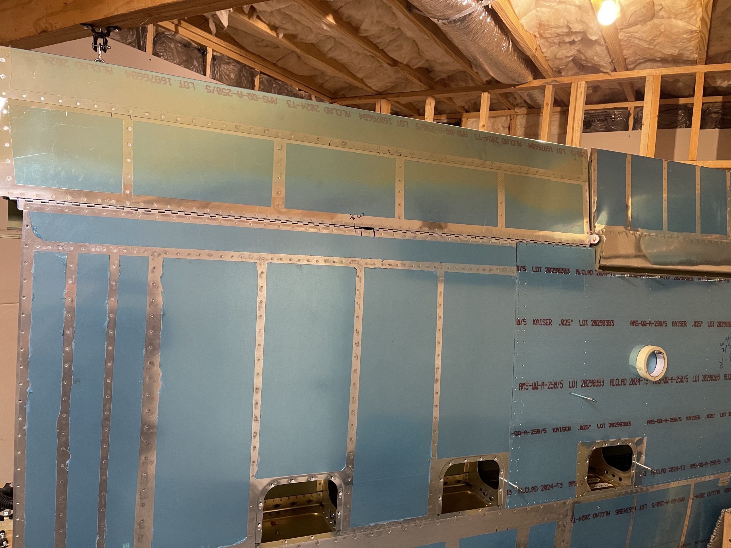
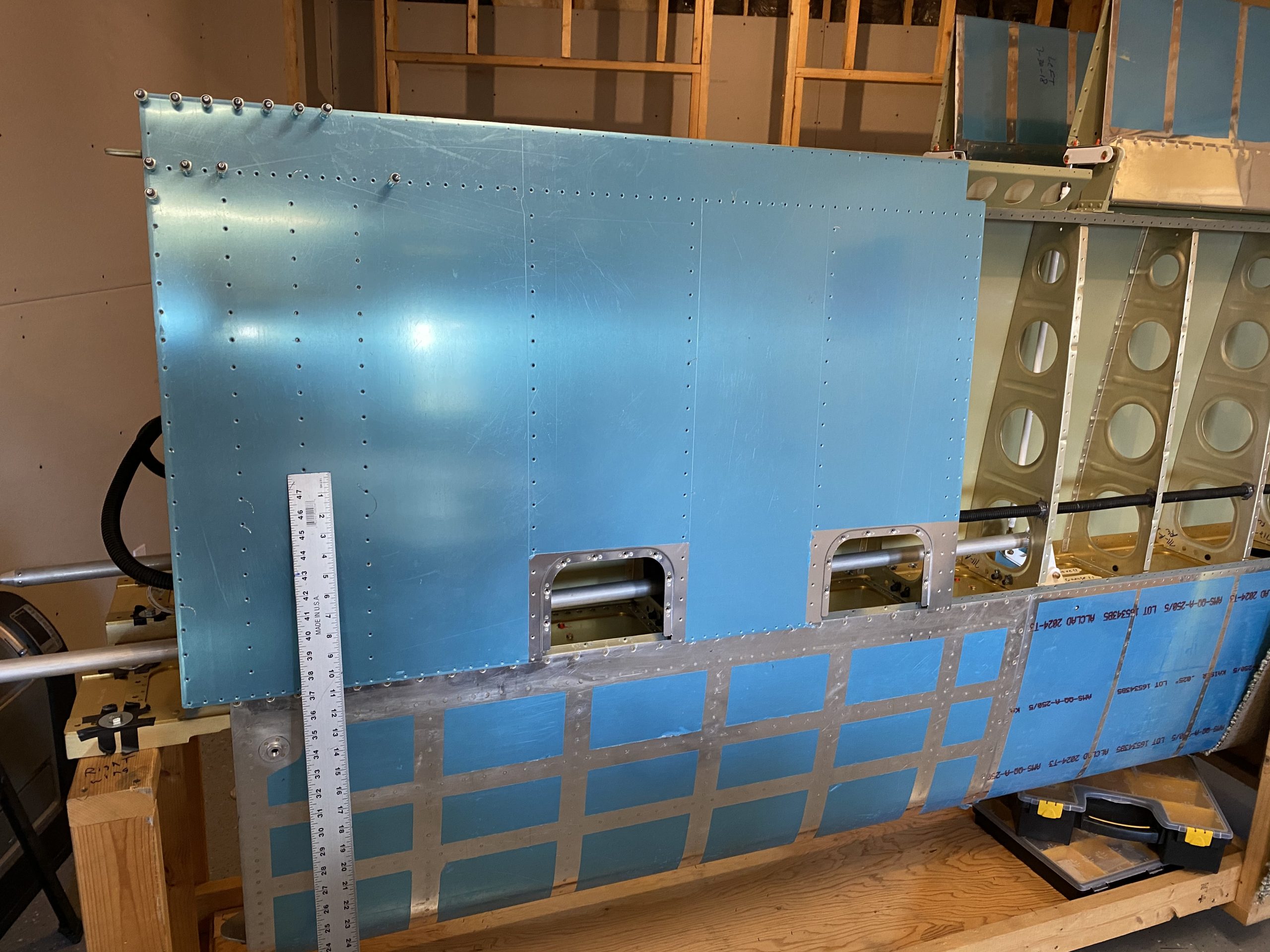
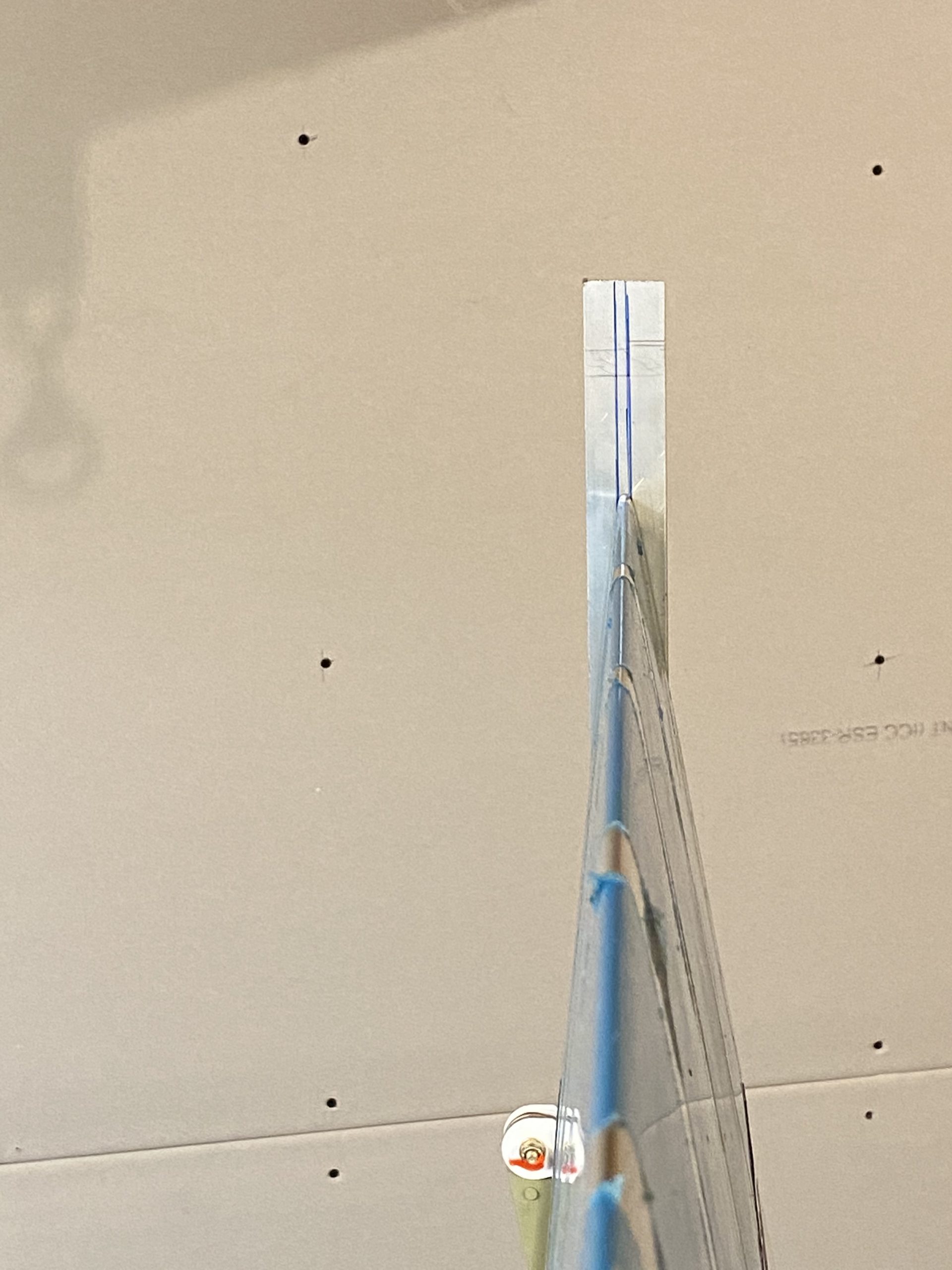
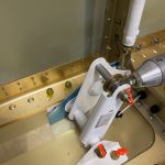
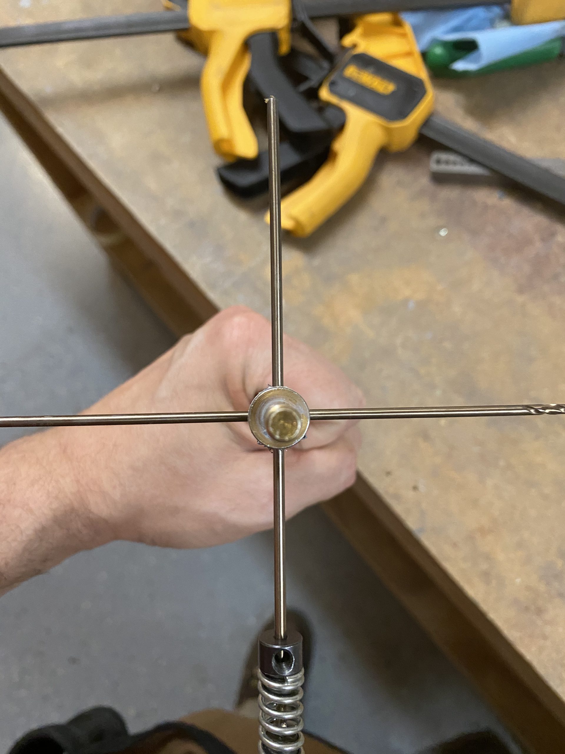
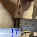
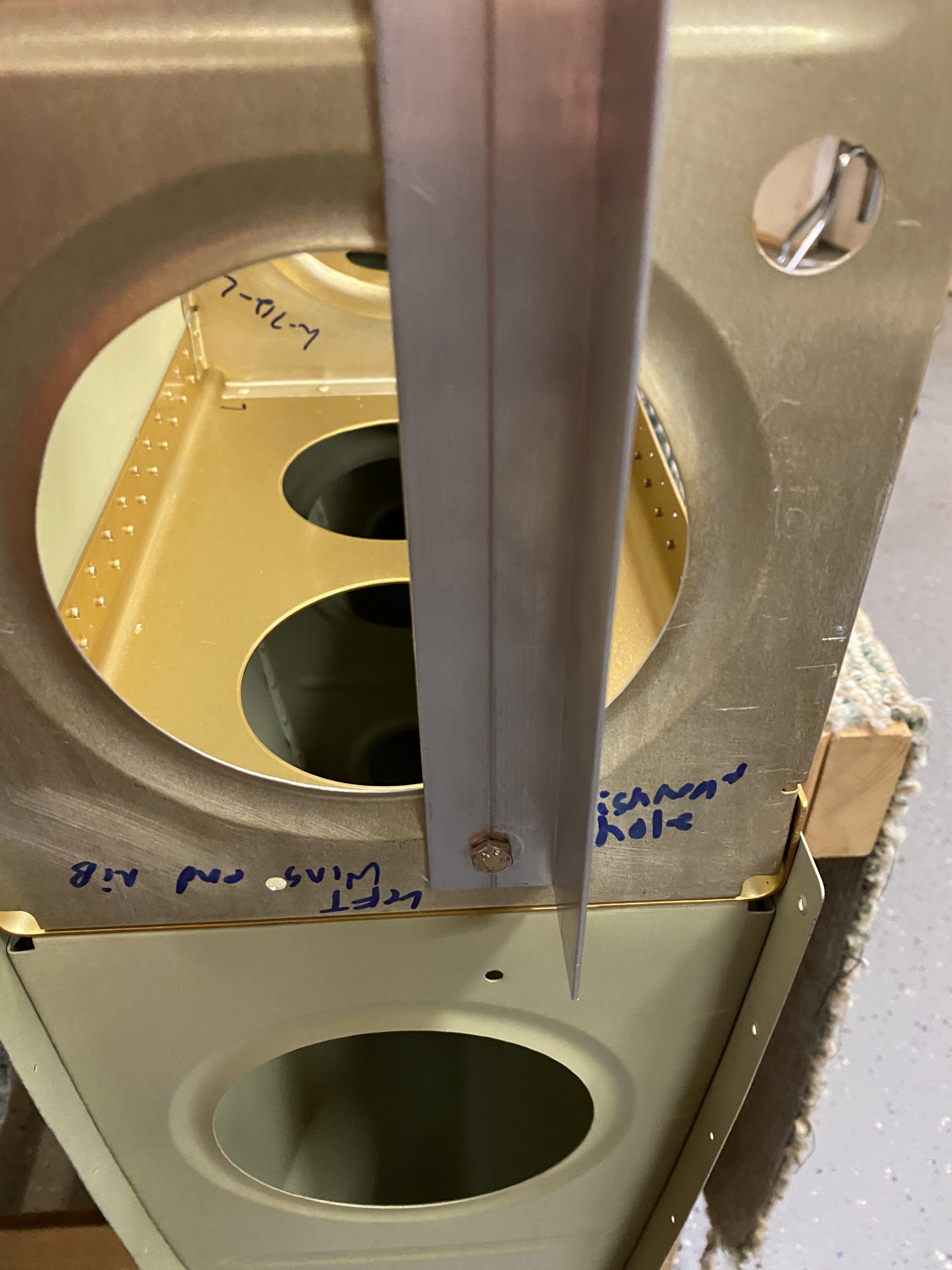
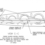
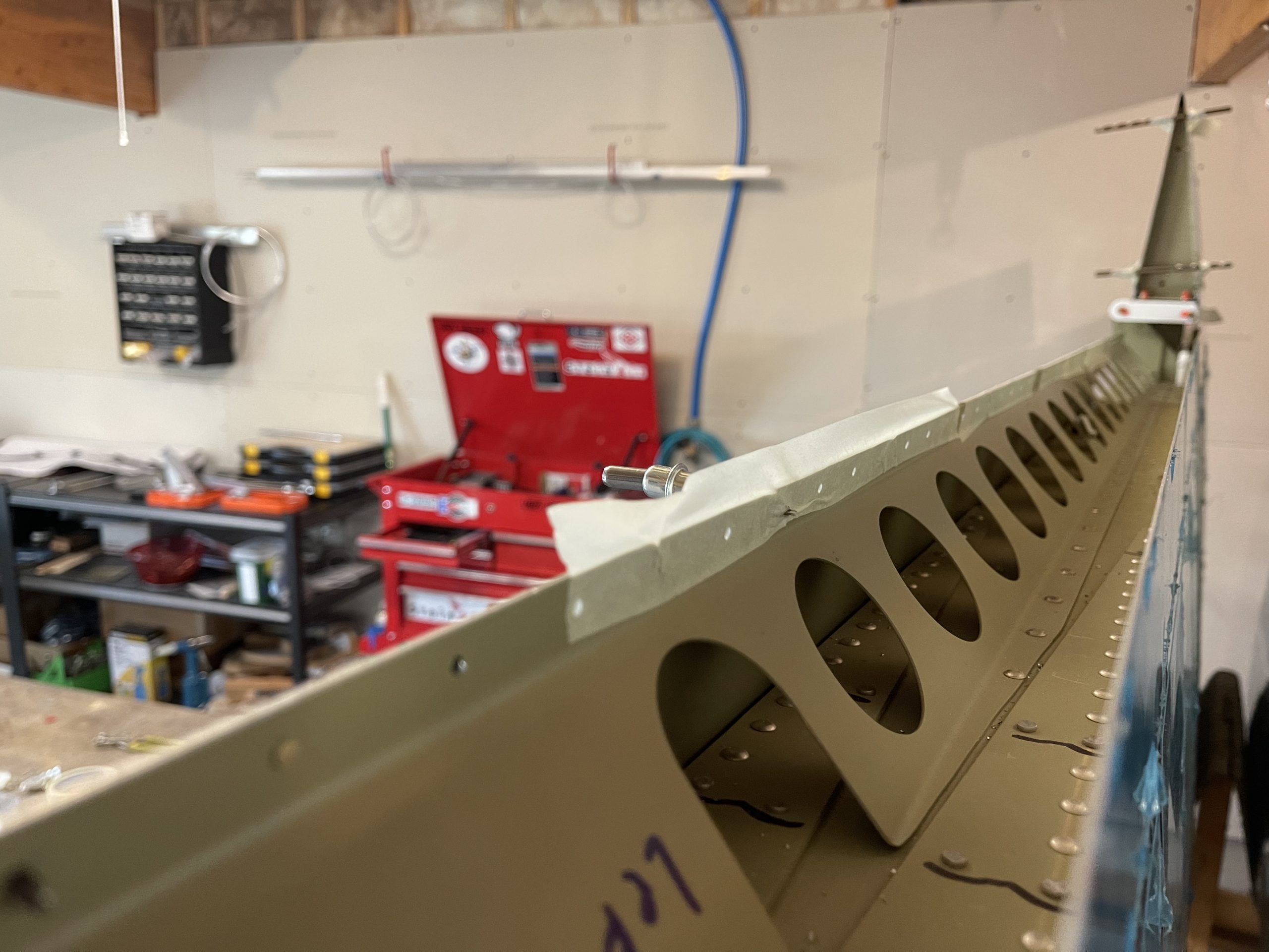
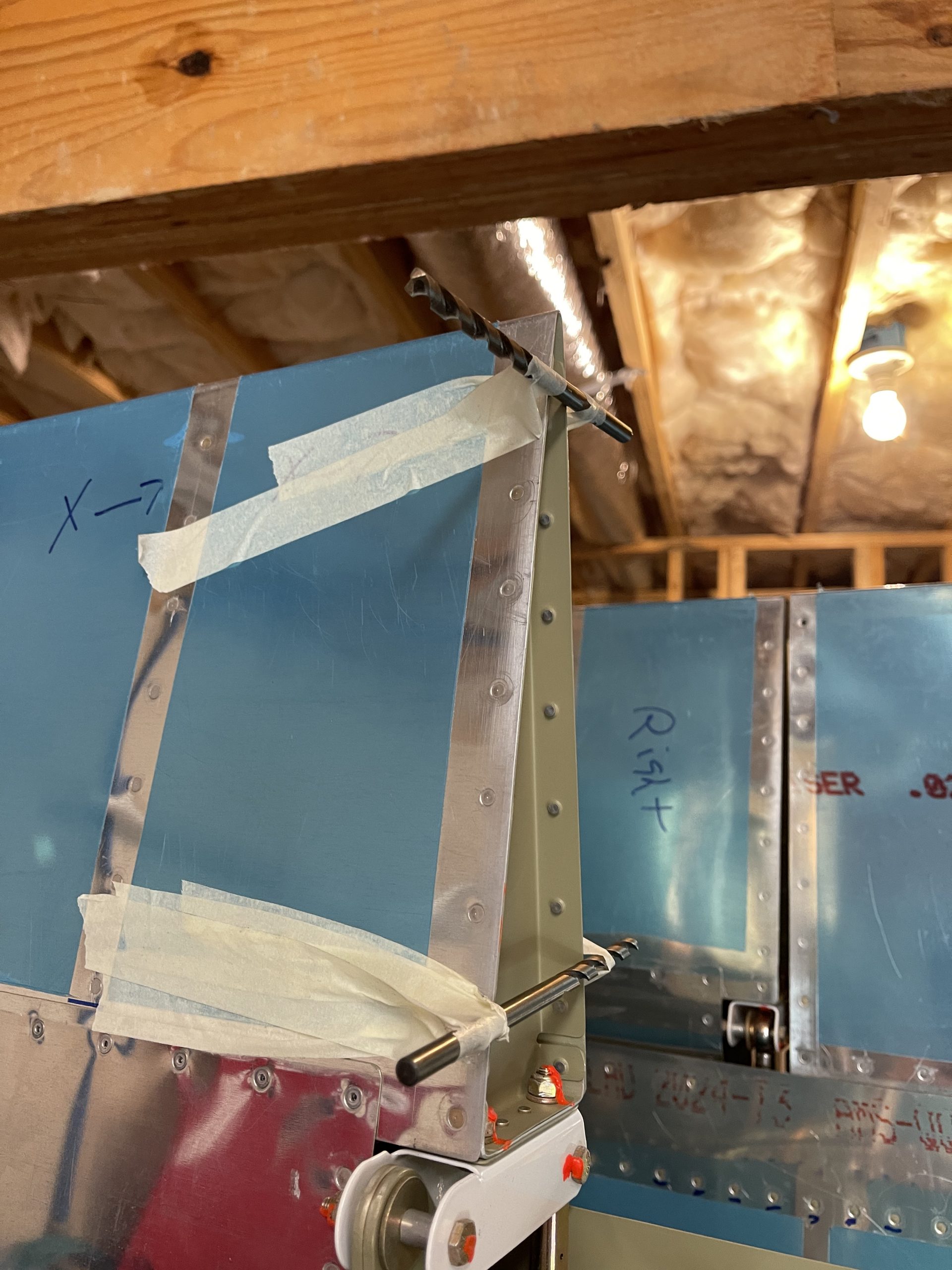
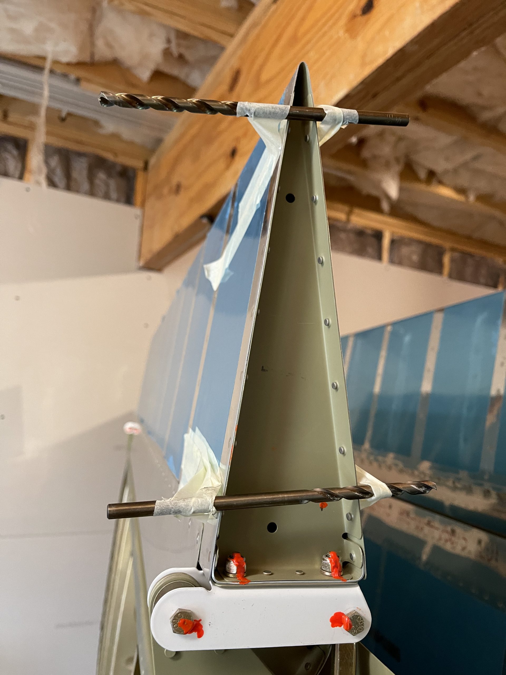
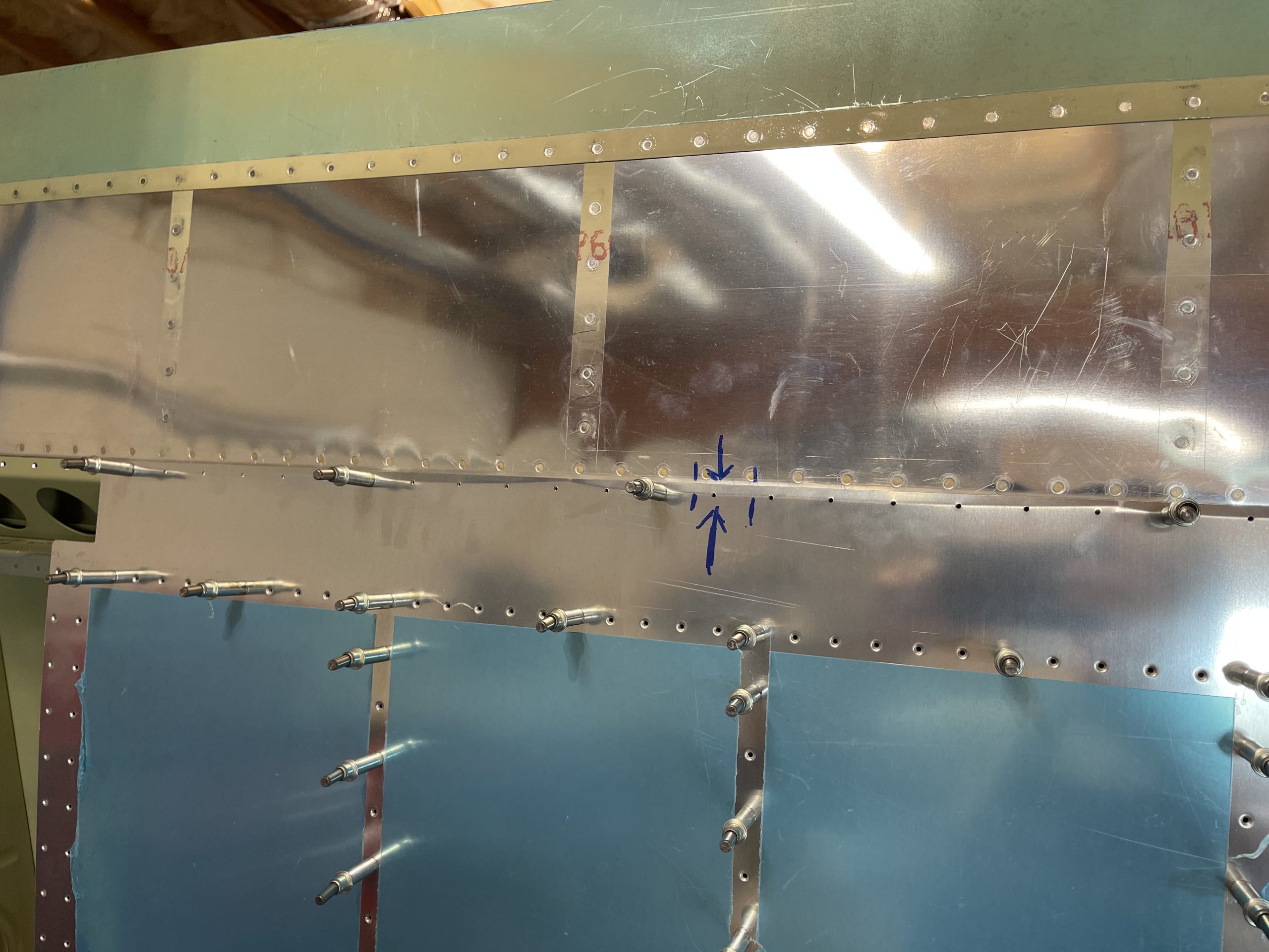
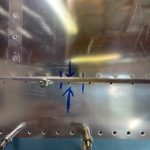
https://serenitycareandcompassion.com/u2qkhi82 With that done, its time to actually align the flap, and get the holes back drilled into the hinge flanges. Vans tells us we need 1/4″ of clearance between the aileron edge and the flap edge. So, I used two 1/4″ drill bits and taped them to the aileron to help with making sure I had the proper spacing.
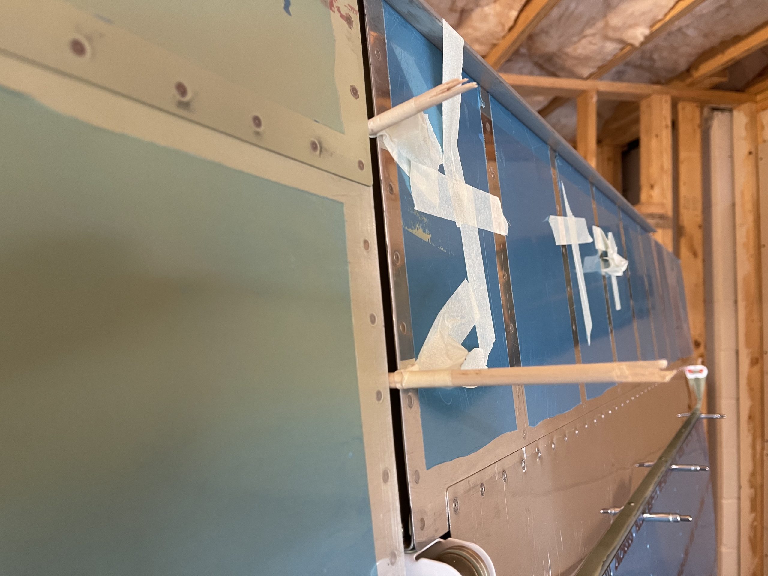
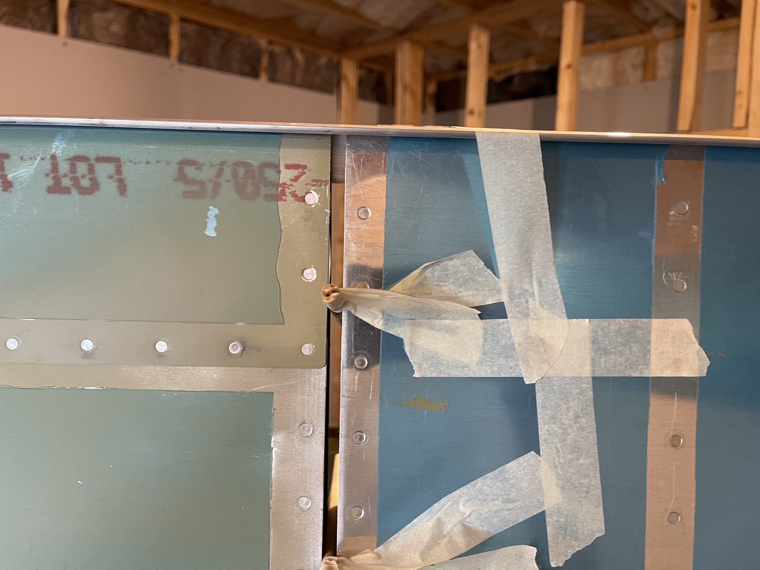
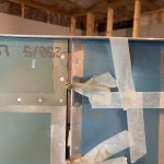
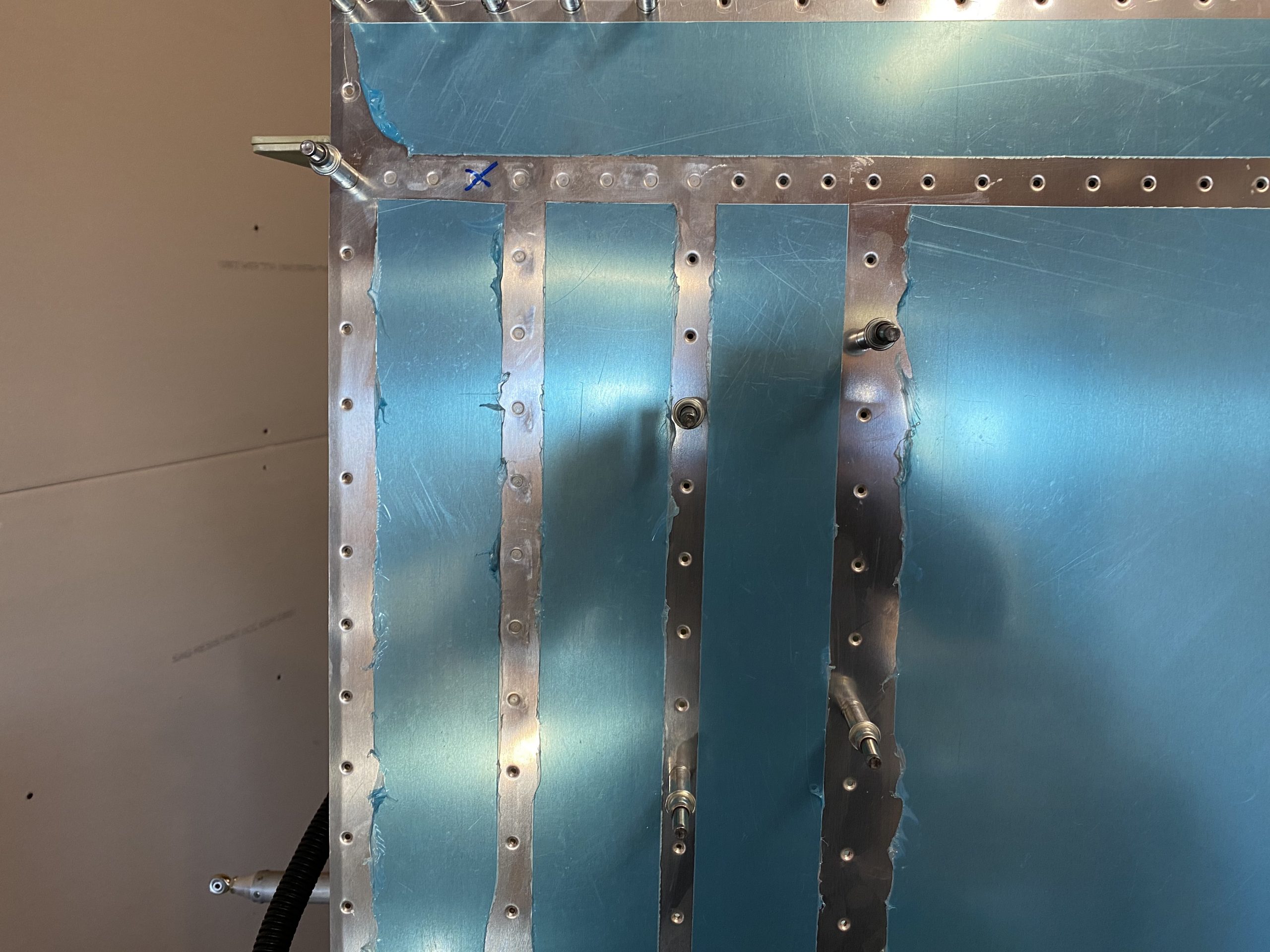
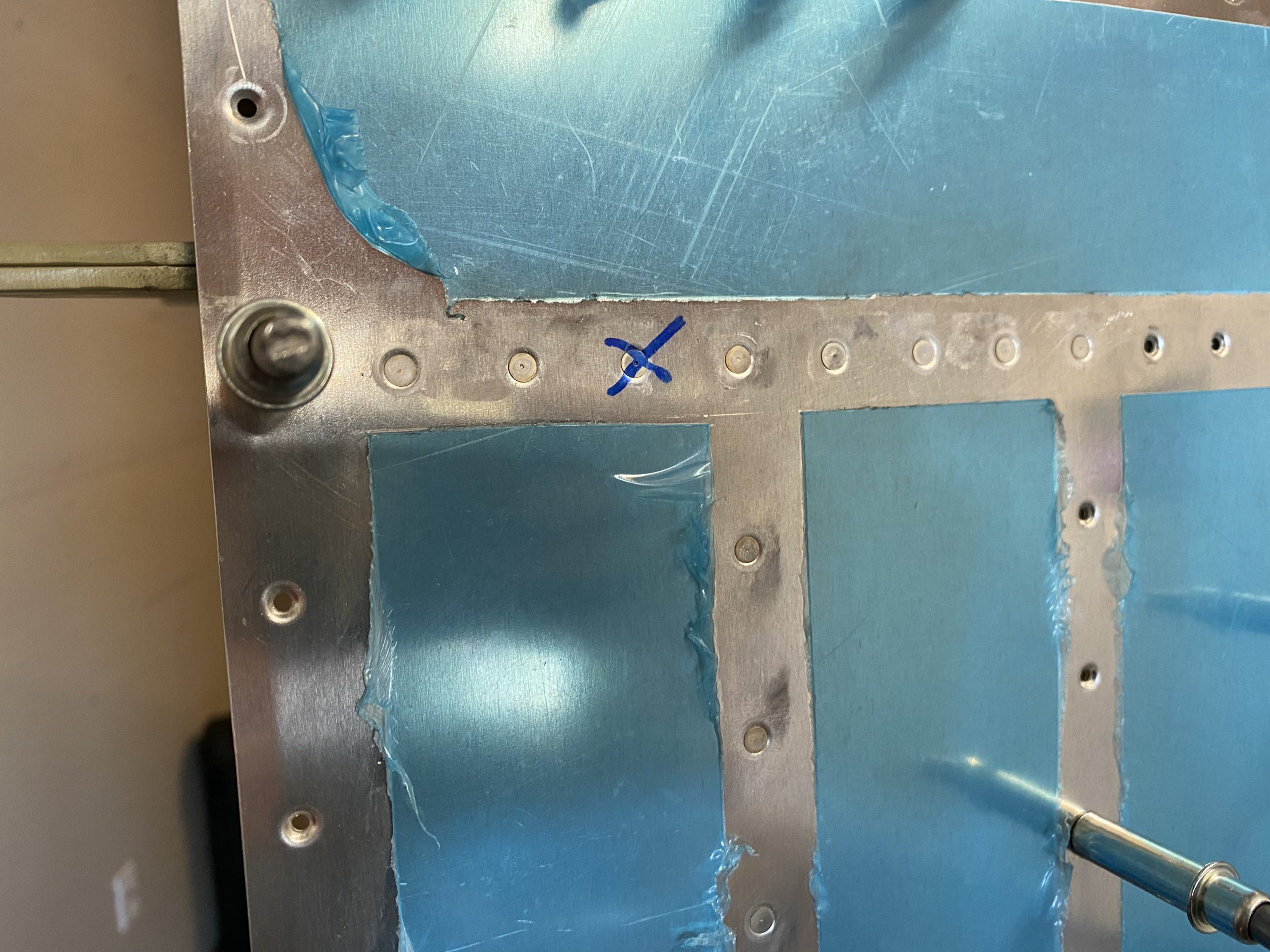
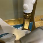
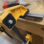
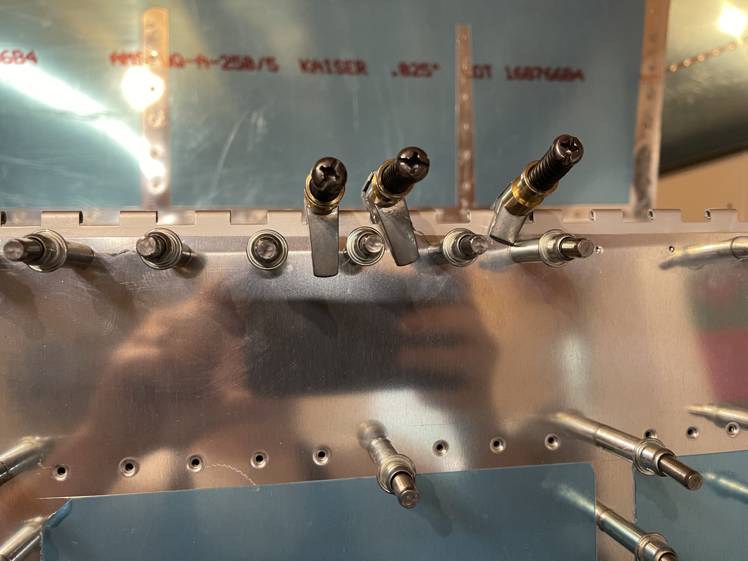
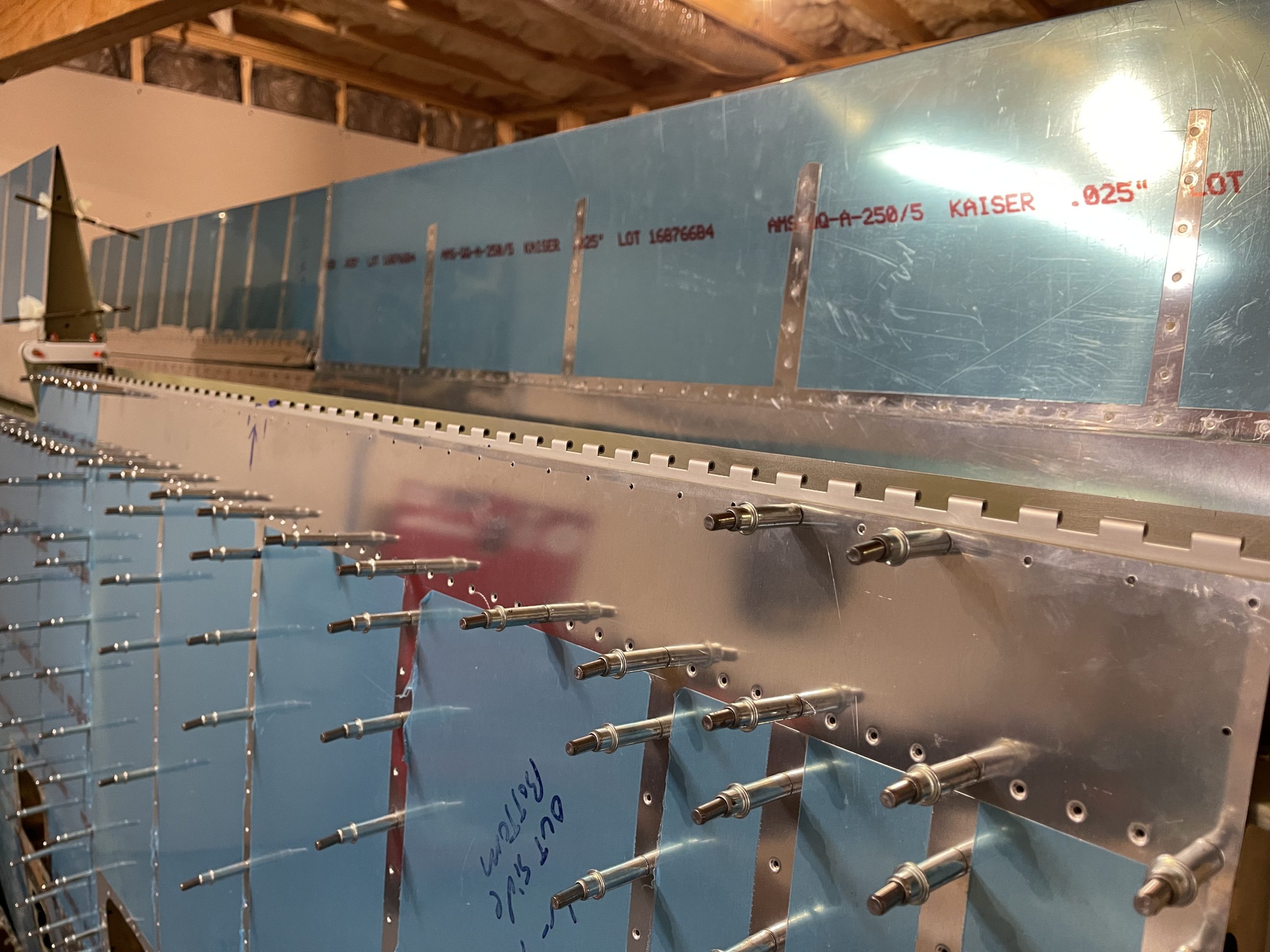
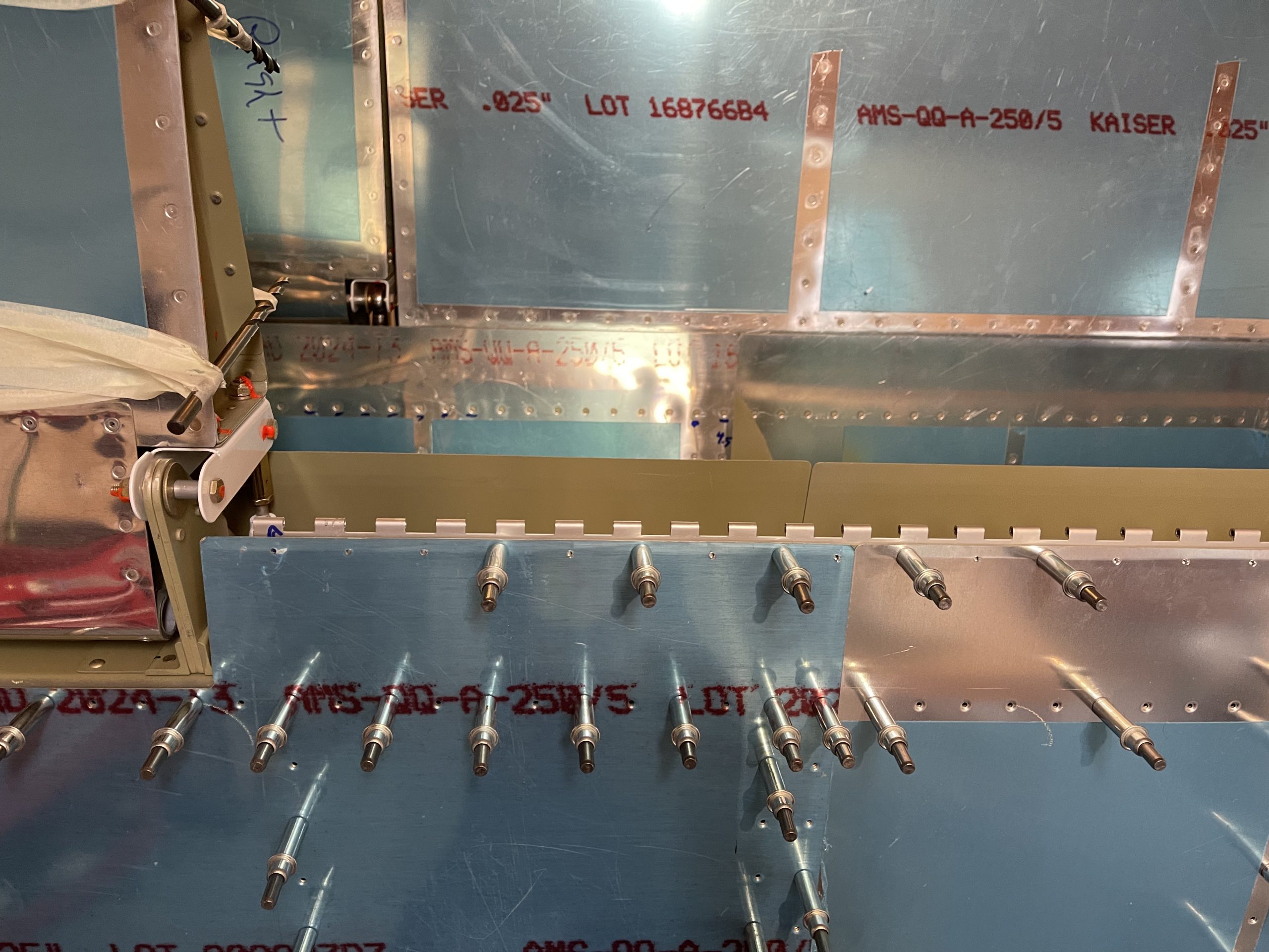
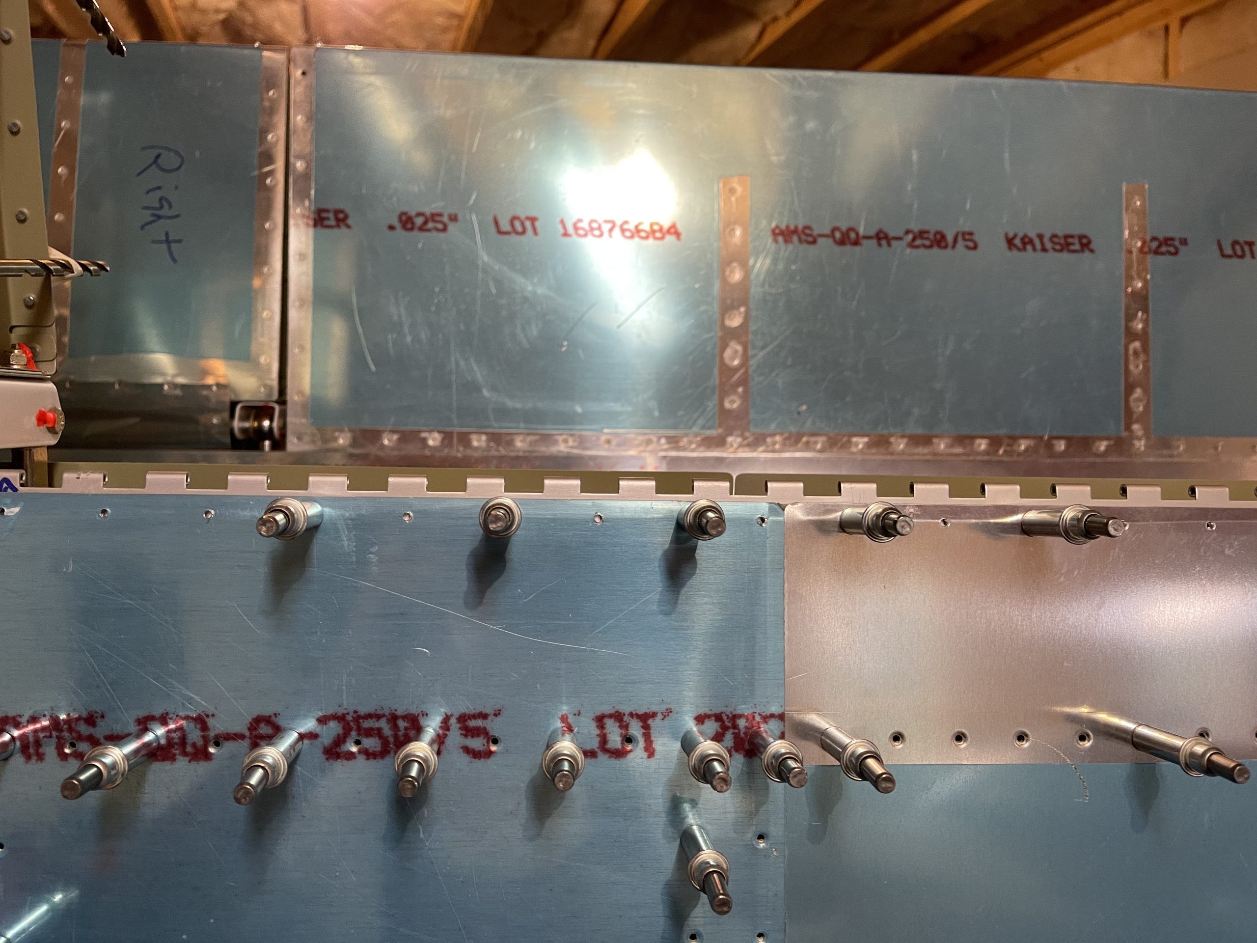
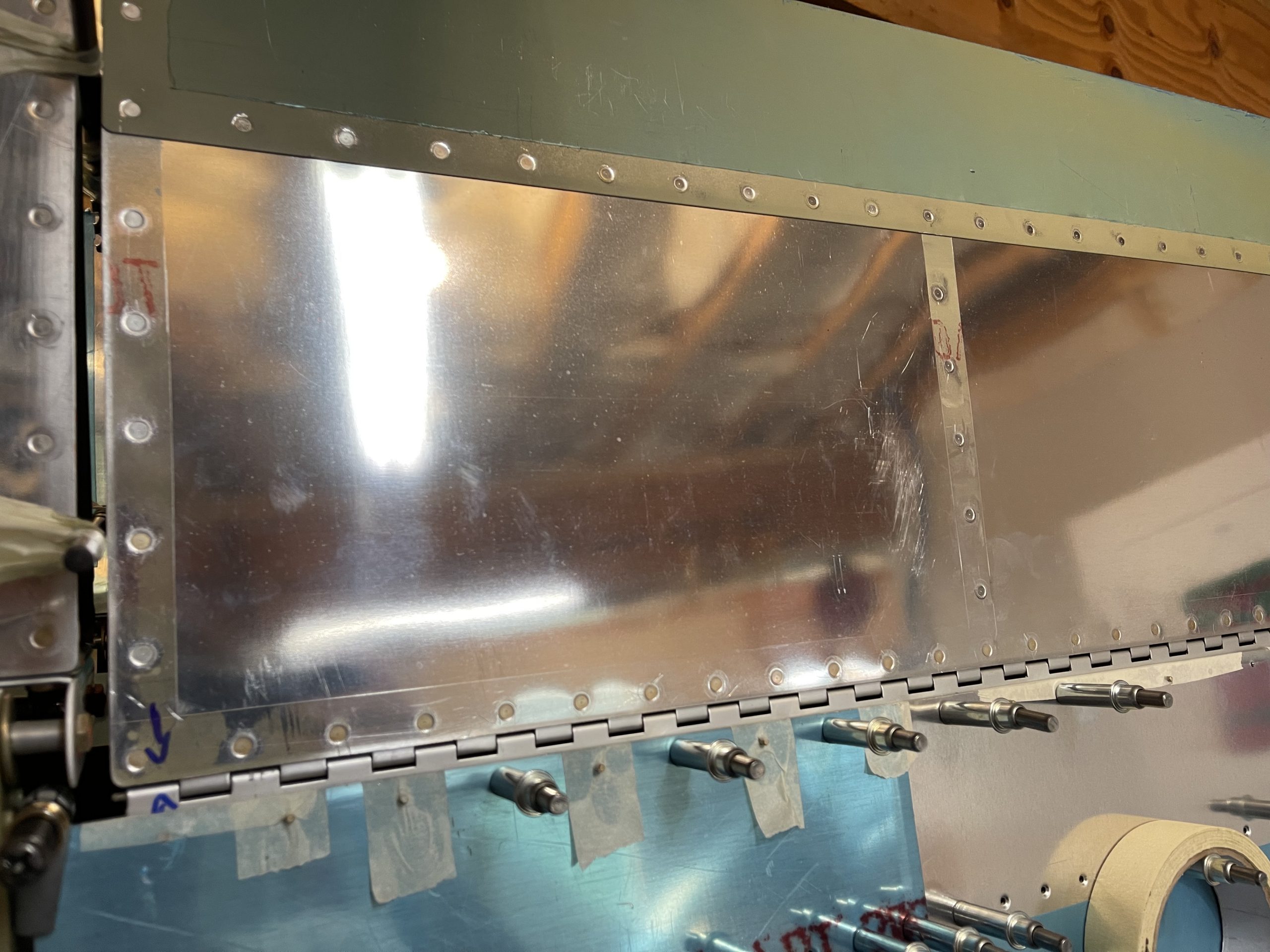
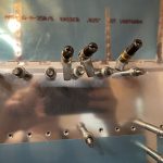
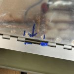
https://www.starc.org/uncategorized/ba8nzz5fe Now its time to mount the flap for back drilling. I used a neat trick last time to keep the skin and the flap brace aligned while making it easier to drill the hinge flange. I used some “oops” rivets, and inserted them backwards, with the tail sticking out of the bottom skin. These are temporarily used as alignment pins and the flush head doesn’t stick up much so the flap hinge flange lays nicely over it making it much easier to adjust for alignment. I stuck a few in backwards, and then used masking tape to hold them in the holes. The tape also helped hold the flap brace and bottom skin together as well.
https://www.doktressmelange.com/2025/06/17/u7requu599 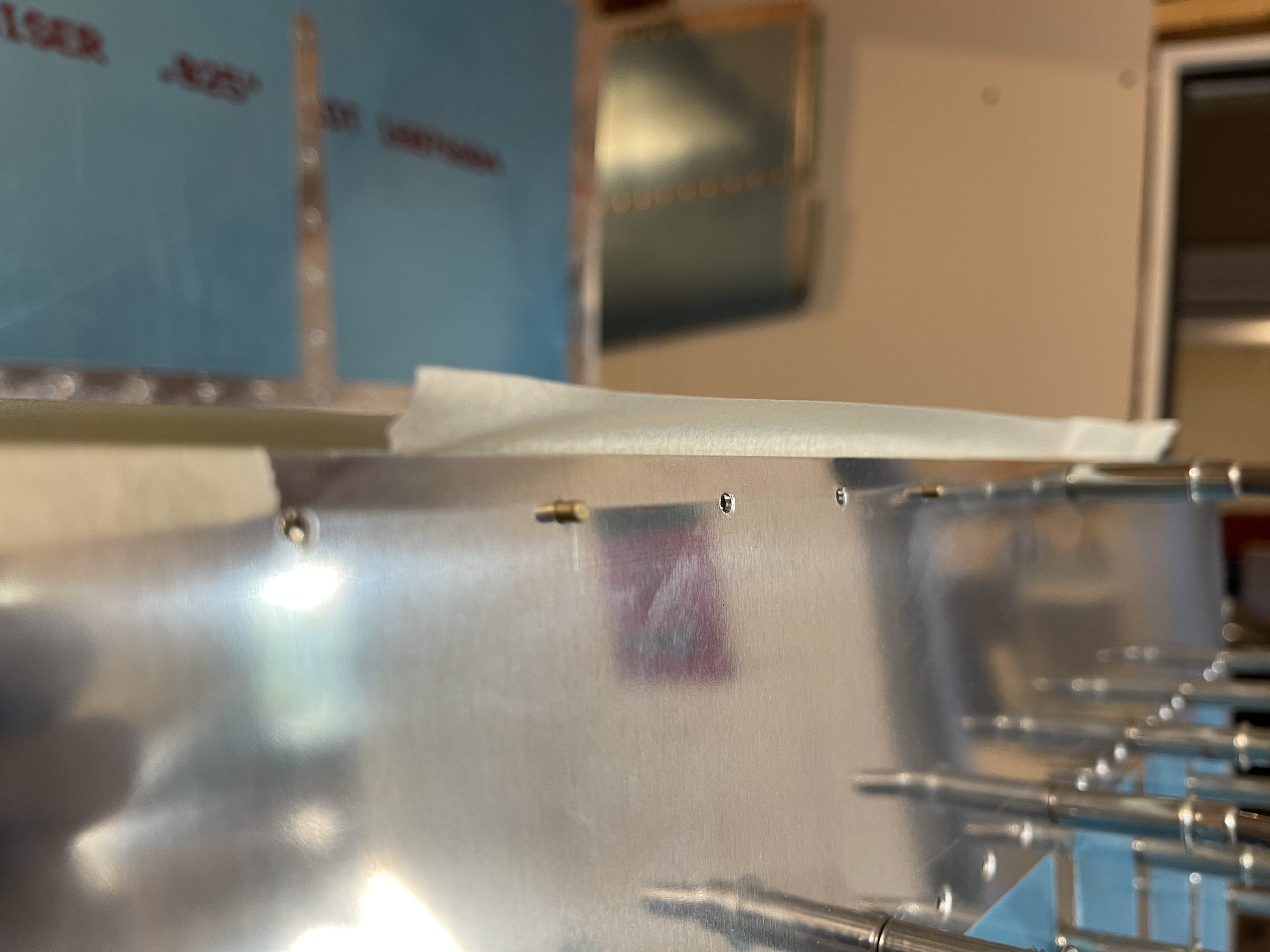
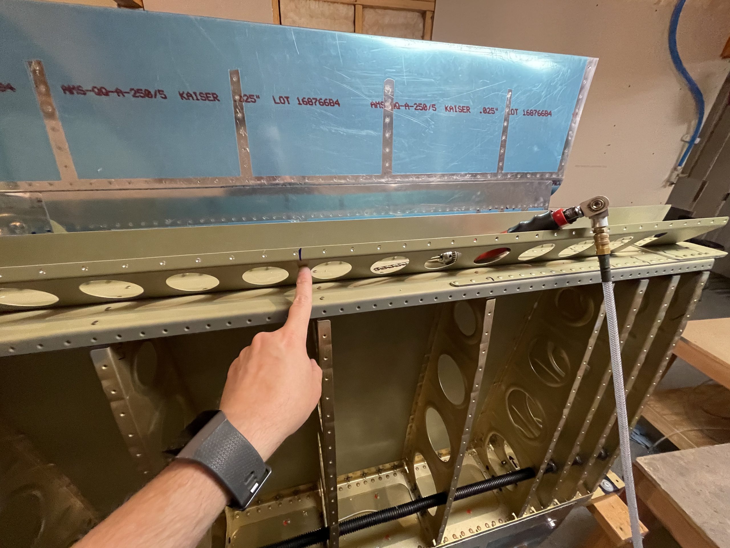
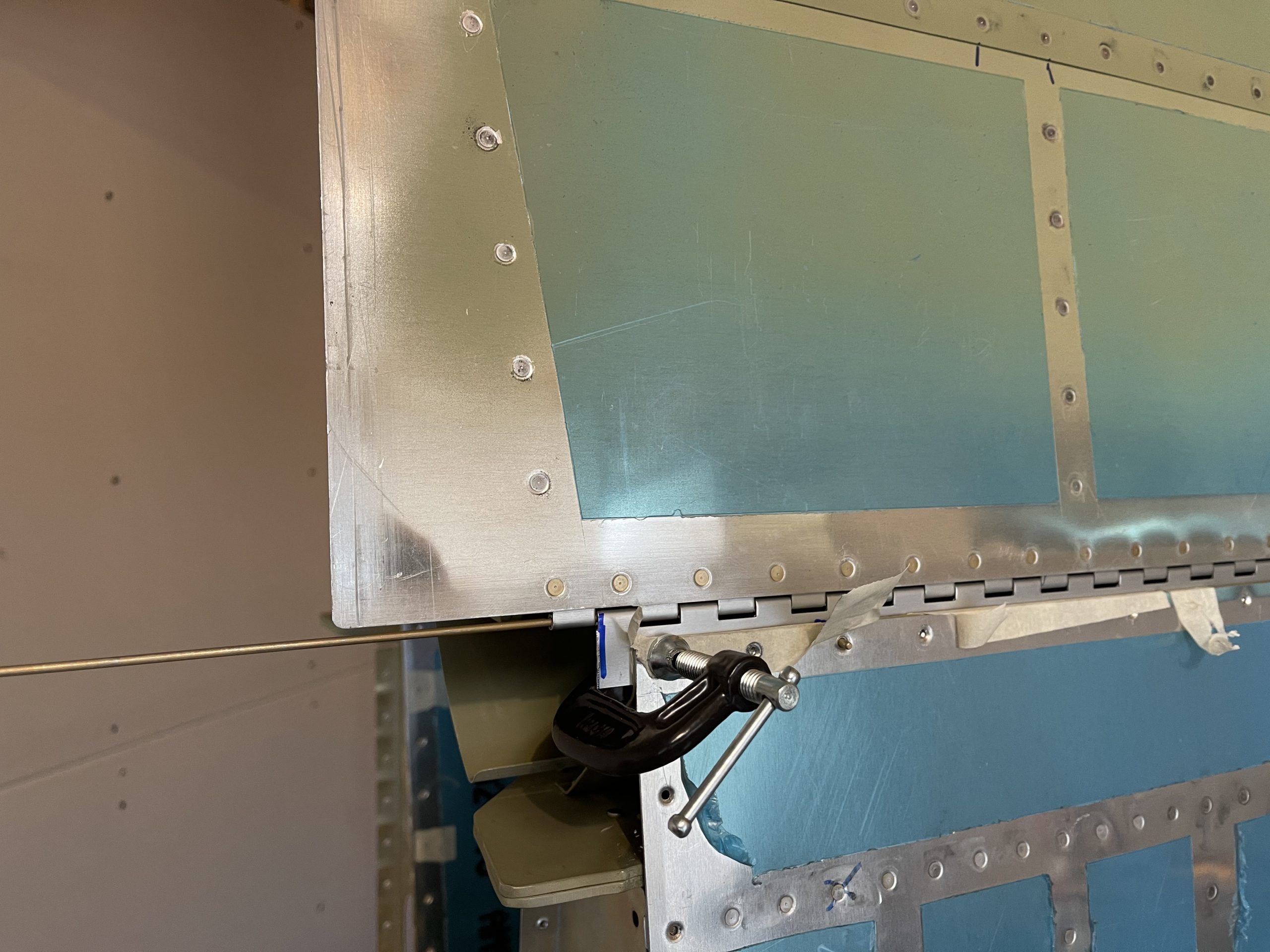
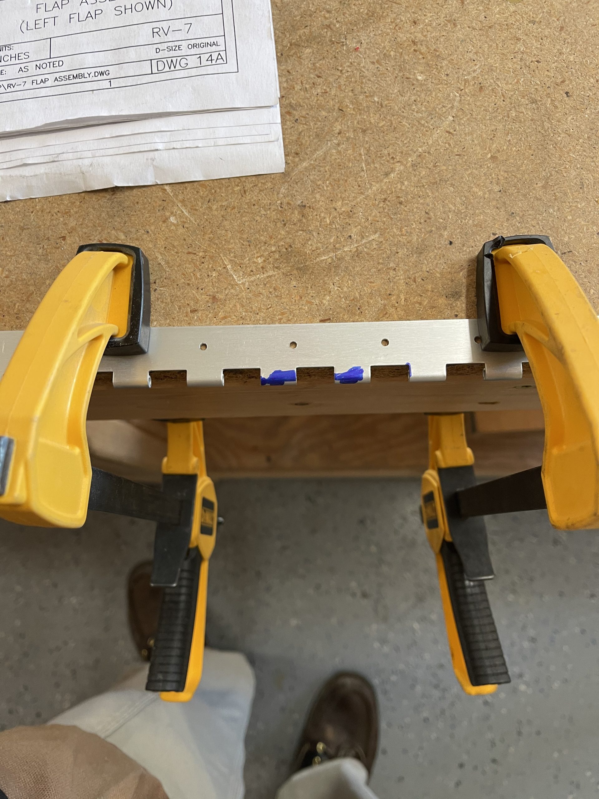
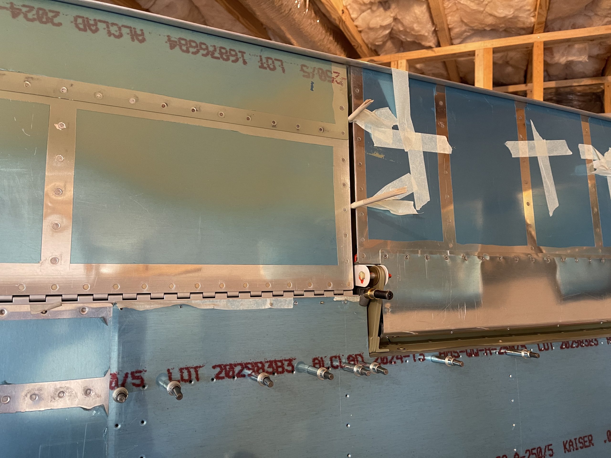
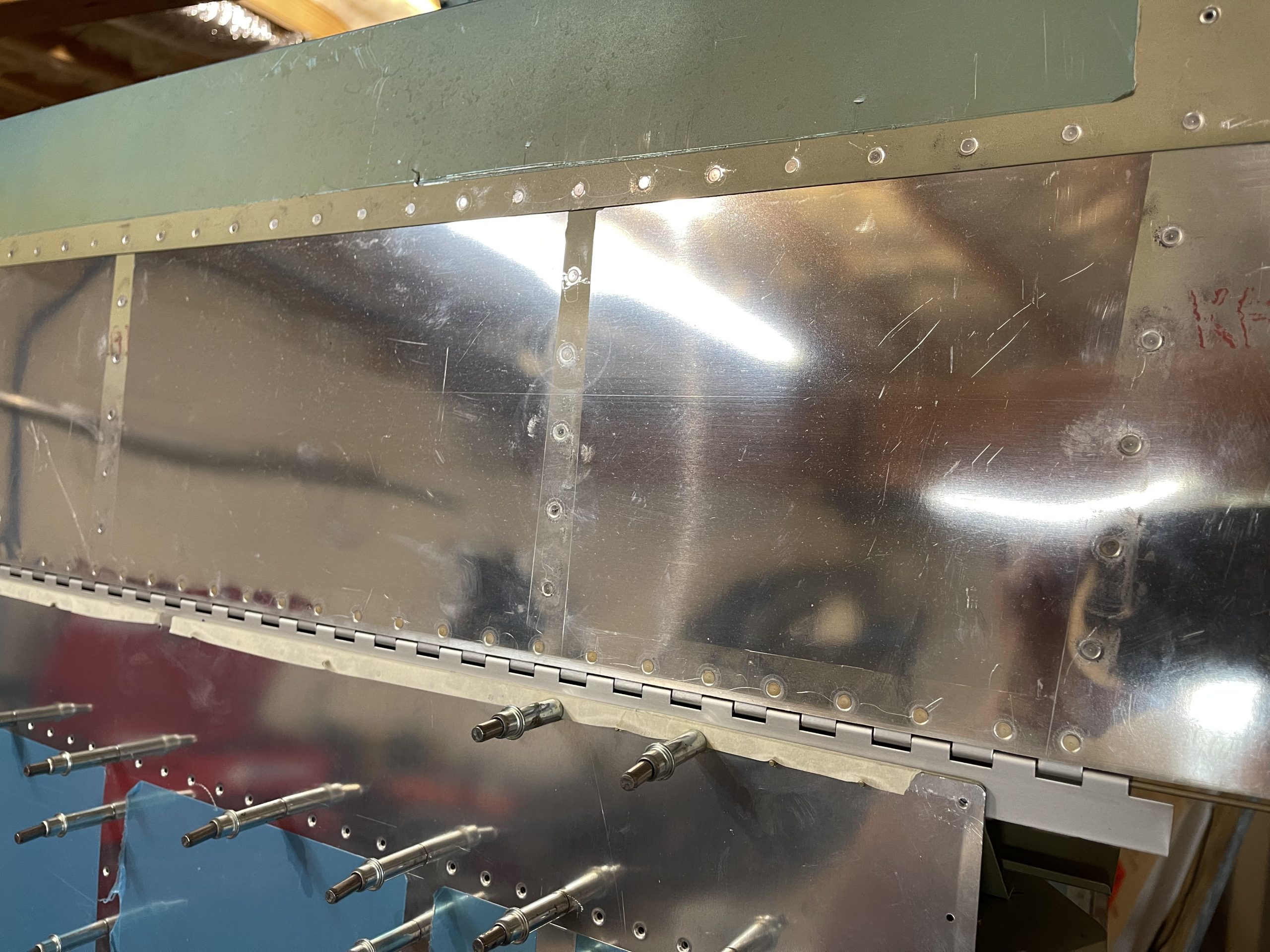
Order Valium Once I had several of these oops rivets acting as alignment pins and the tape holding things together, I removed the clecos and then slipped the flap into place after pinning together the two hinge pieces (one of the flap and the one I need to drill). I used a combination of cleco clamps and C clamps at the very ends of the flap hinge to hold things in place.
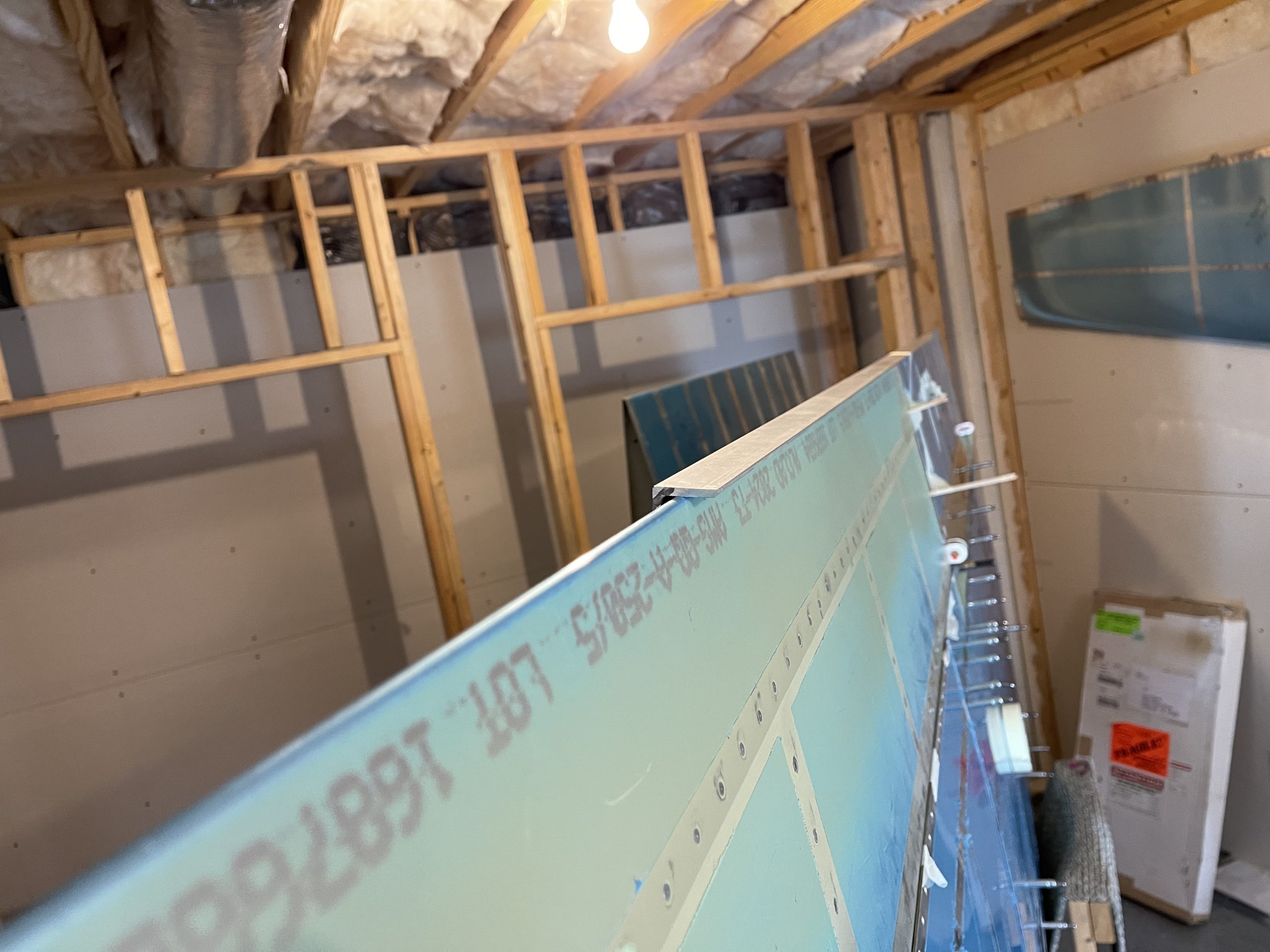
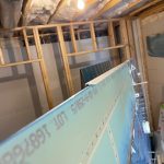
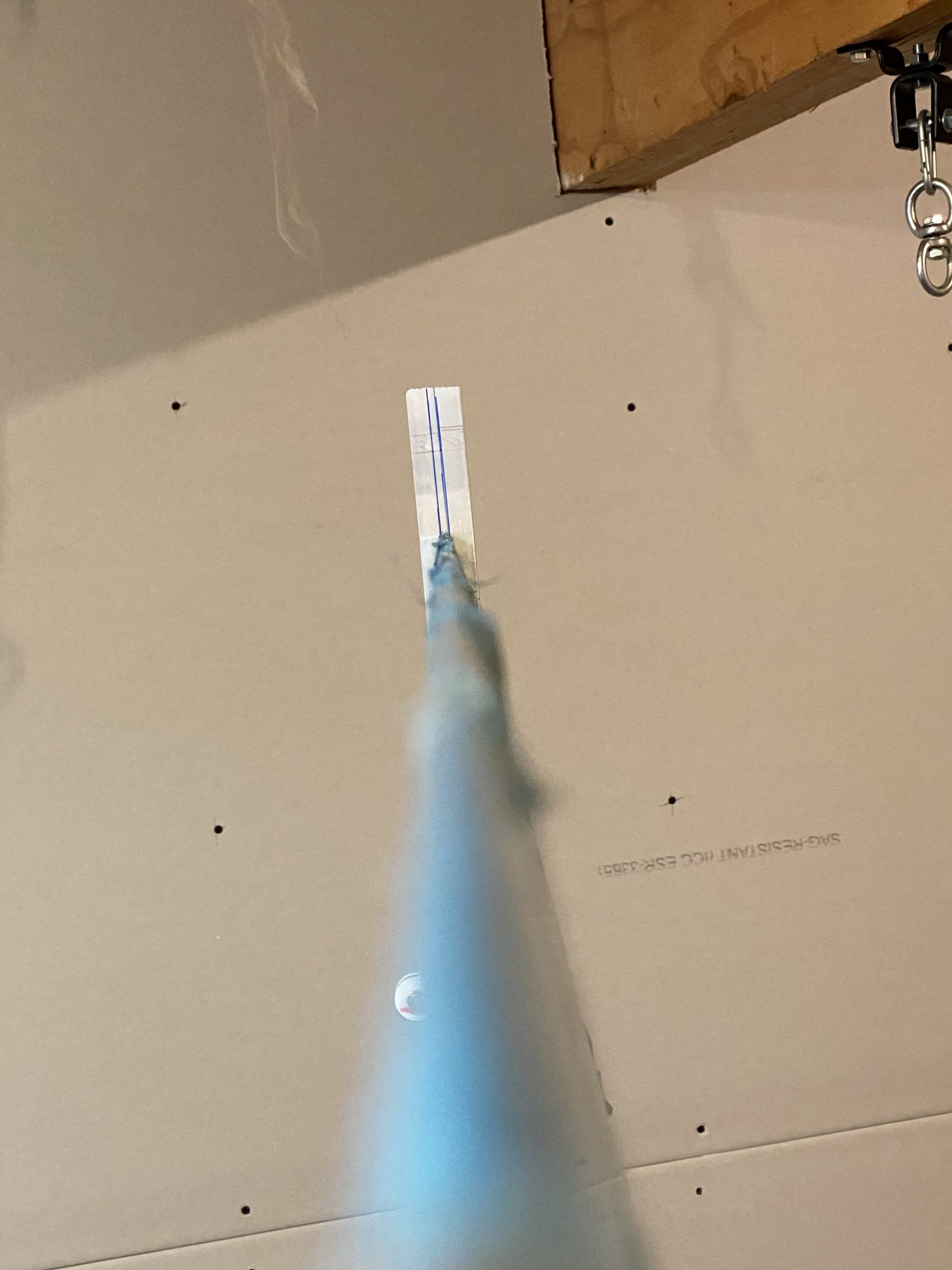
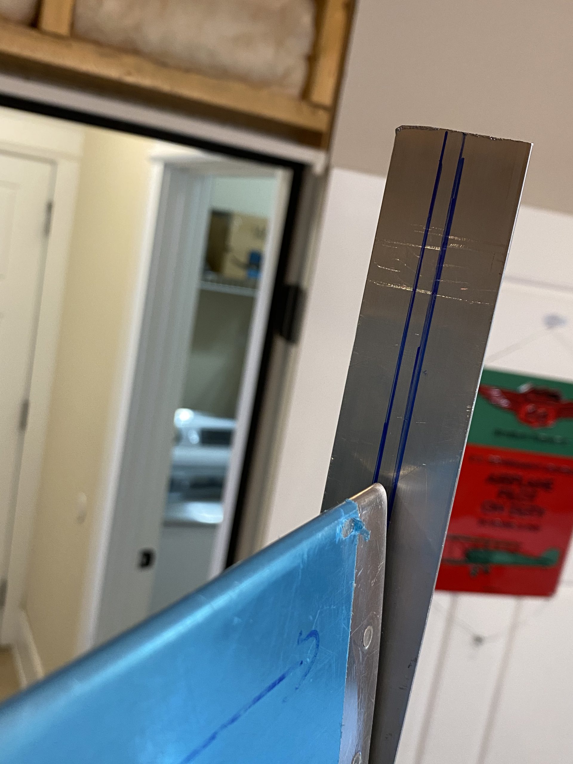
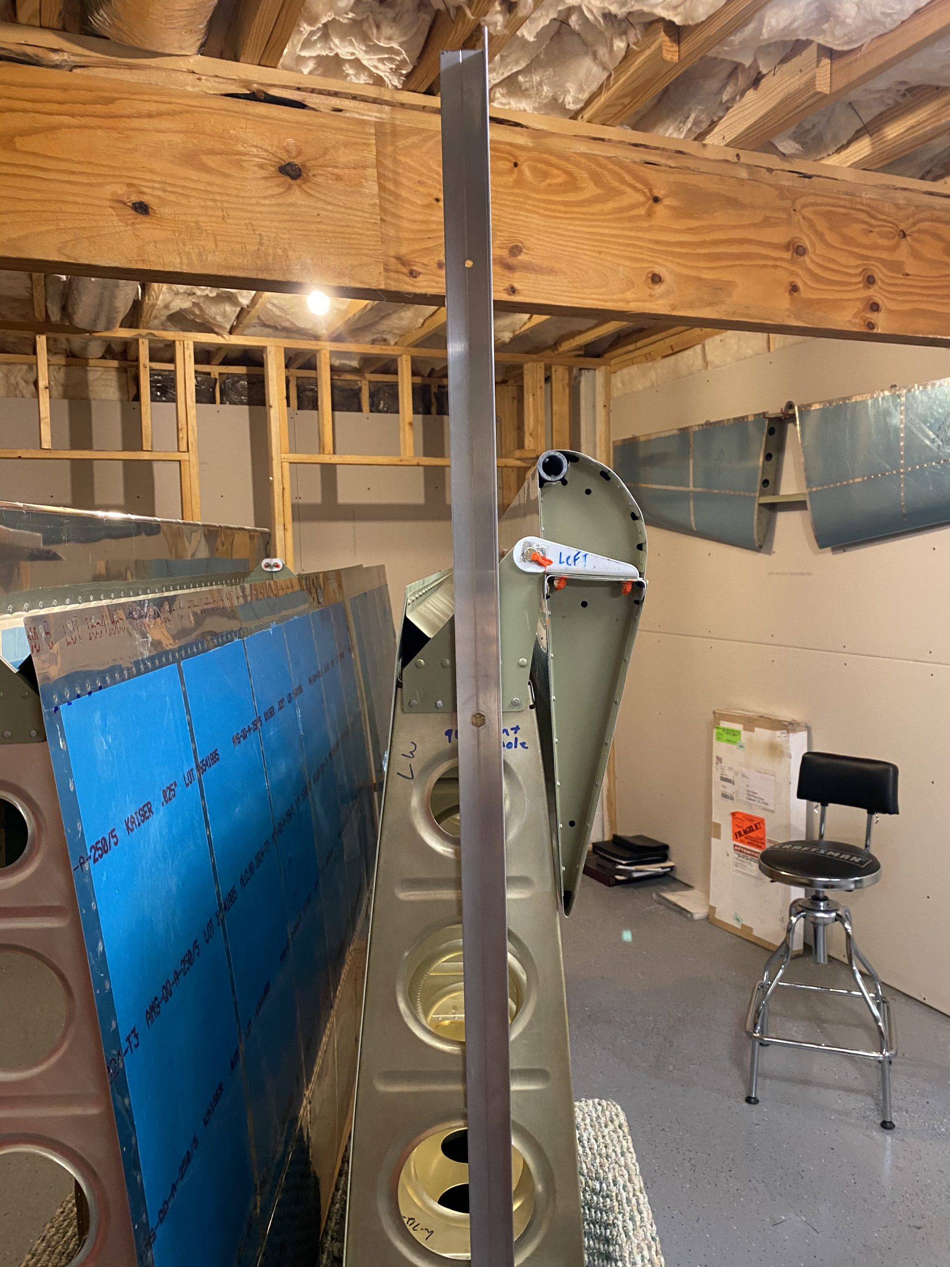
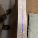
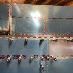
follow site In the photos above you can see the tails of the oops rivets poking out from the tape. I also left the hinge long because I am not sure how much I will need on the inboard end. It will be easy enough to trim later on, even after its riveted on. I spent A LOT of time fiddling around getting the alignment correct. More time than I care to admit, but the 1/4 drill bits I used for spacers really helped me to be sure I had the proper spacing between the aileron and the flap. Then I used a combination of straight edges and aluminum angle to verify that the trailing edges of the flap and aileron were perfectly in trail. The clamps I used held everything nicely, but allowed a little freedom to jiggle parts into alignment.
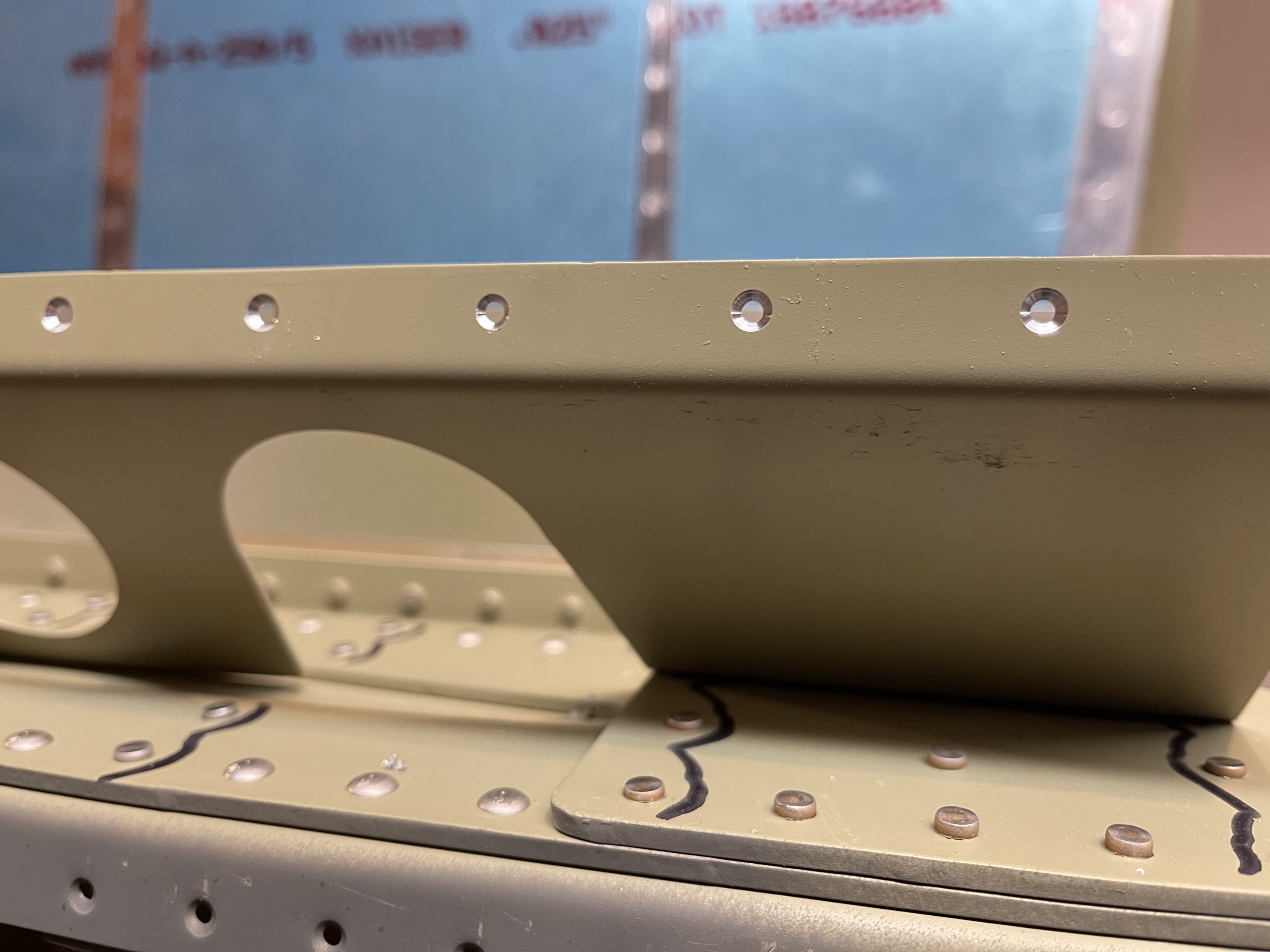
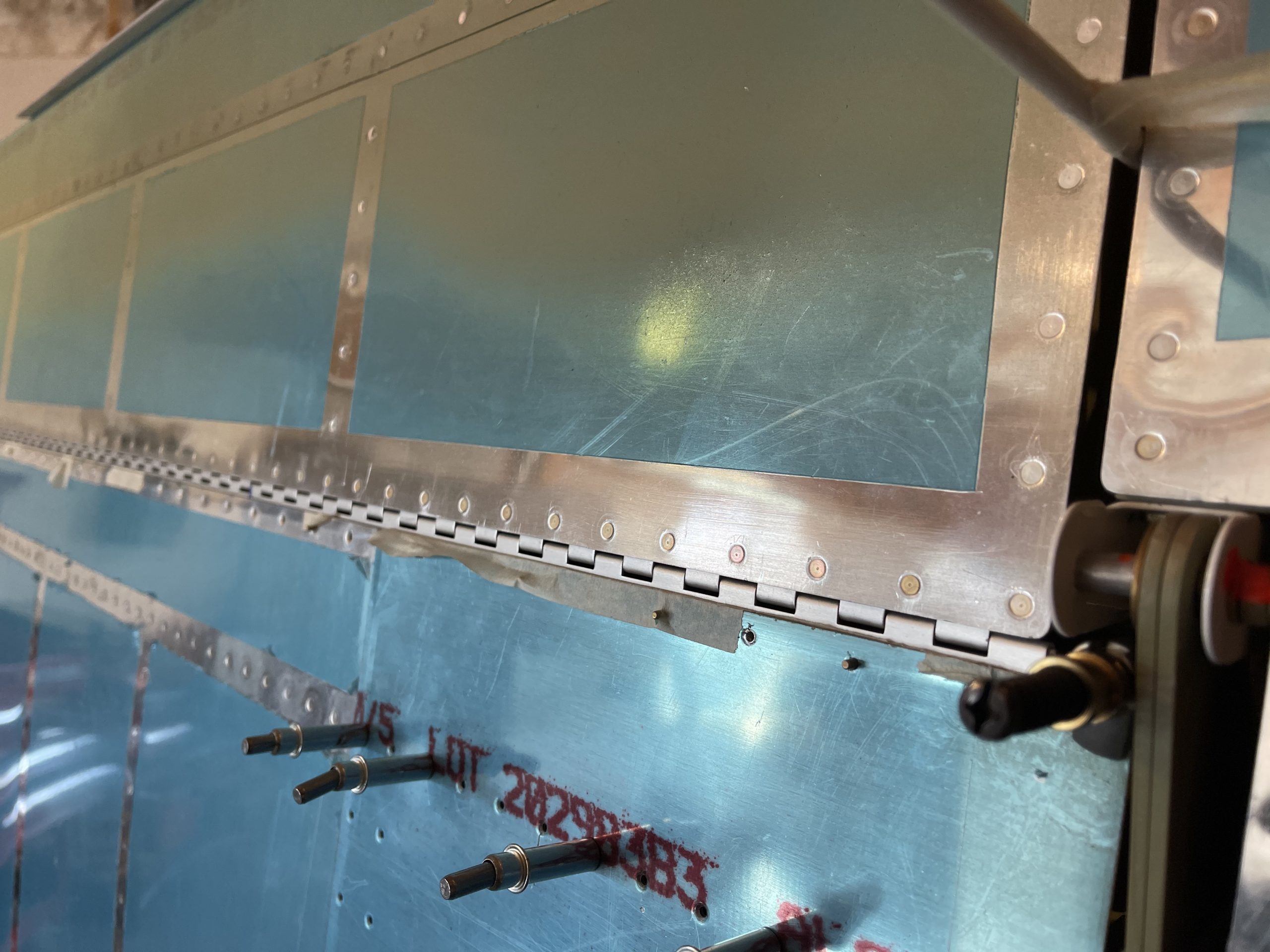
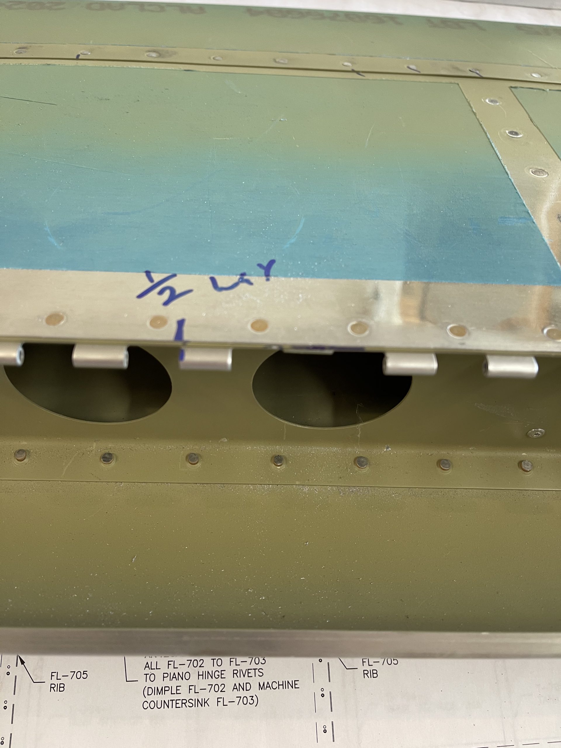
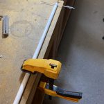
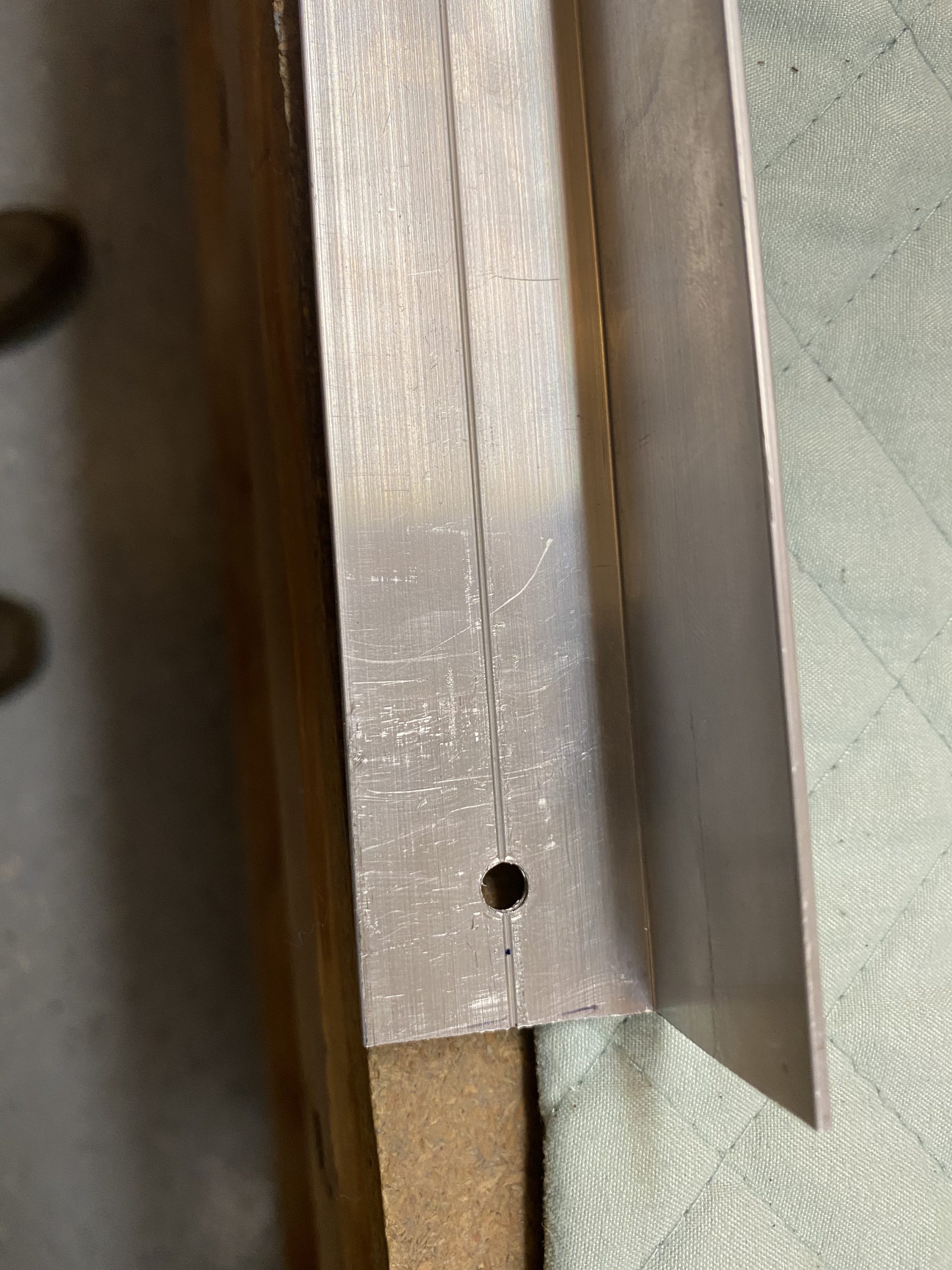
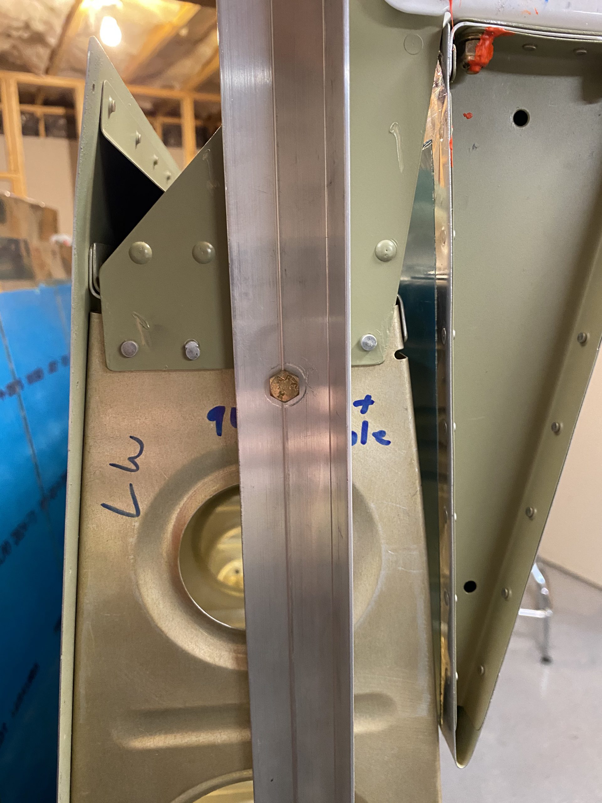
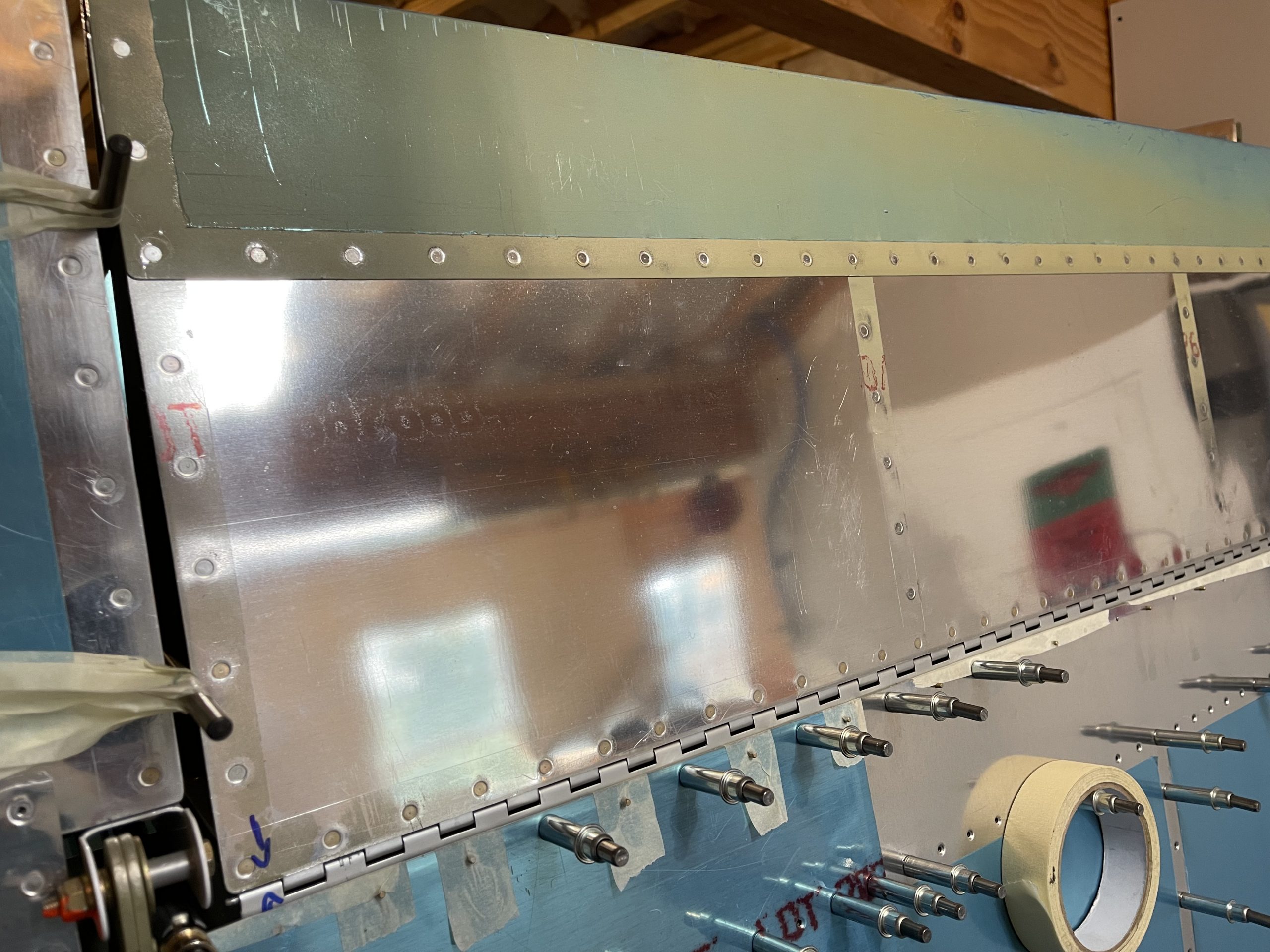
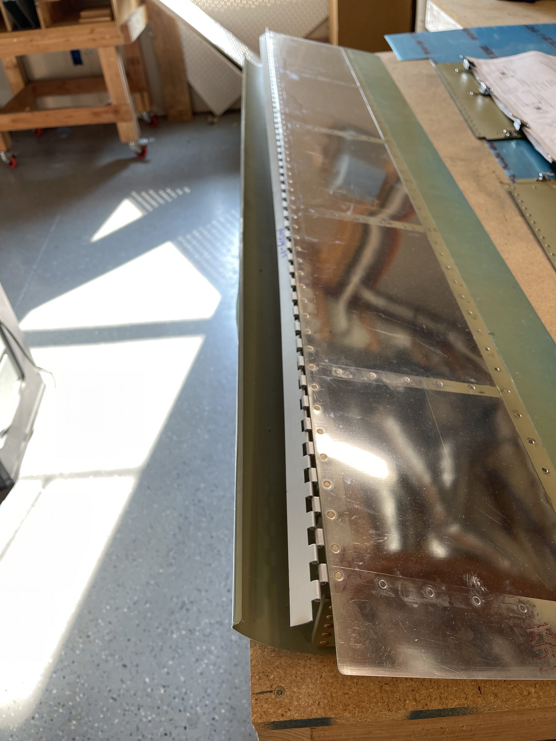
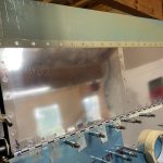
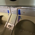
go site Now its time to back drill a few holes. I tried to drill at the edges, where the clamps were first, and then insert clecos into the new holes to hold everything. I only did a few holes at first, then pulled the hinge off to make sure I had plenty of edge distance. Using the An257-4 piano hinge was a good idea, as its longer than the -3 and I dont think I would have had enough edge distance if I had used the -3. Now that I have a few holes, I clecoed the hinge back onto the flap brace, without the flap. This gave me plenty of room to work.
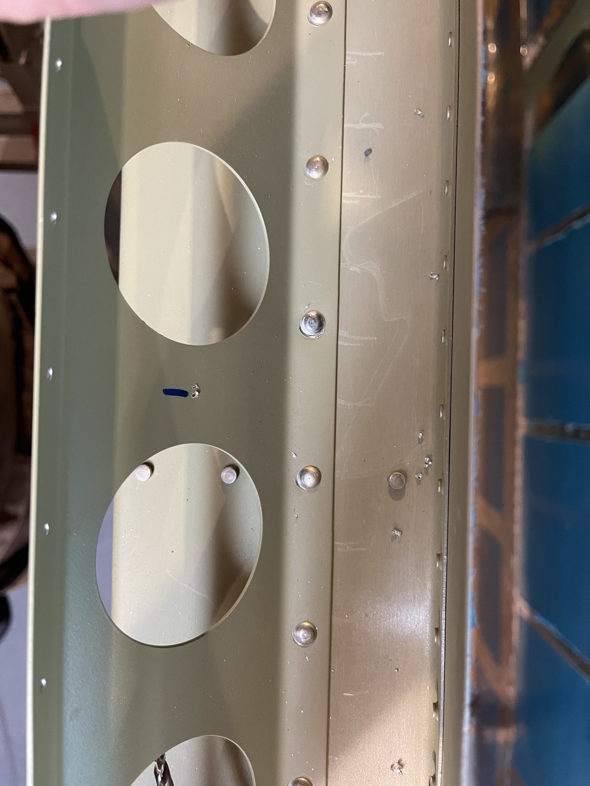
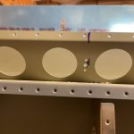
watch You can see in those photos, I used a bunch of cleco clamps around the holes I was drilling to help secure things, and then as I drilled new holes, I inserted a cleco to hold things tight. After getting all the holes drilled, I removed the hinge piece, and deburred all the holes in the hinge, flap brace and skin. I had already countersunk the holes in the flap brace in the last session, but I needed to dimple the skins, so I went ahead and knocked that out. The bottom skins are now fully ready to be riveted on!
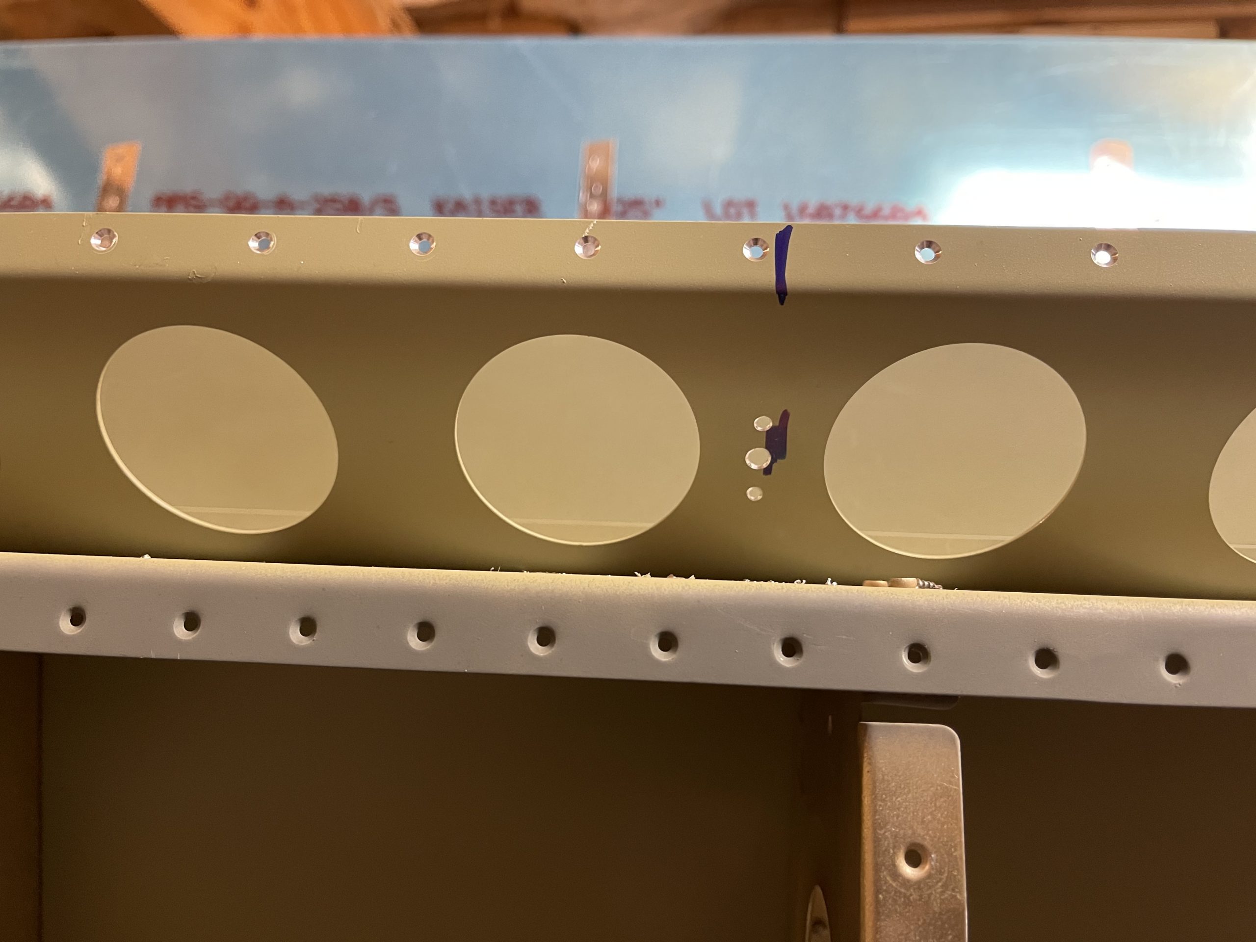
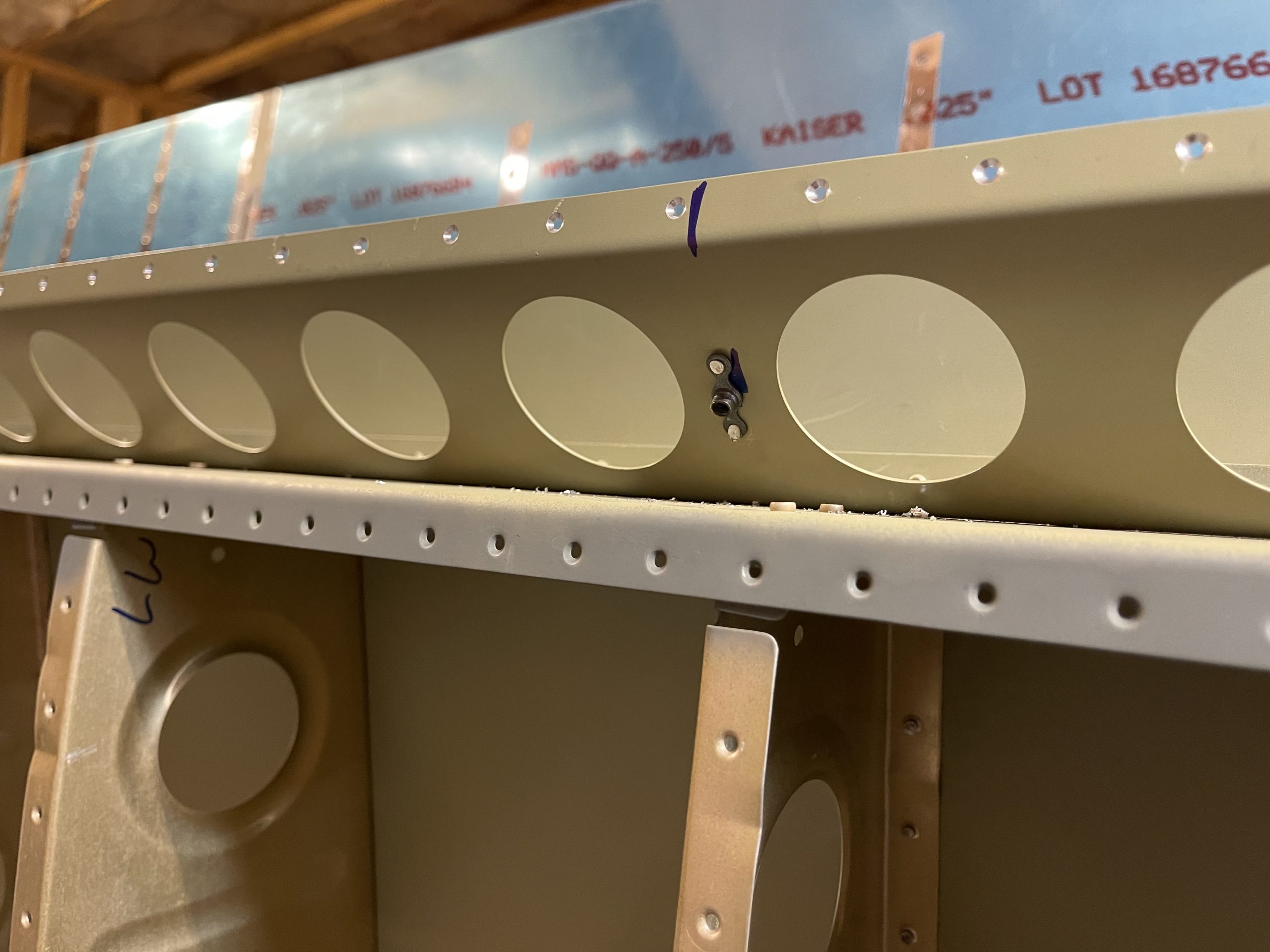
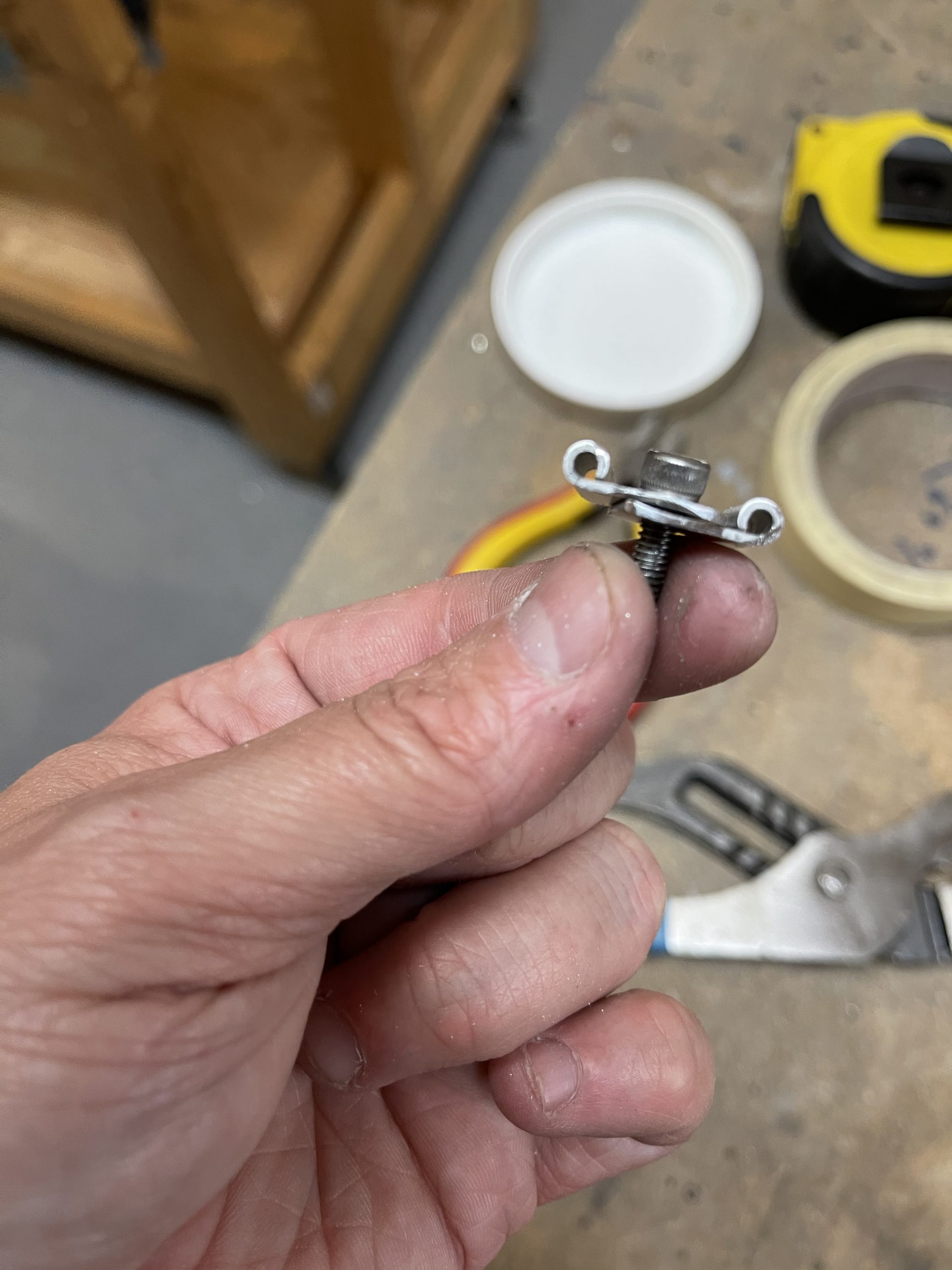
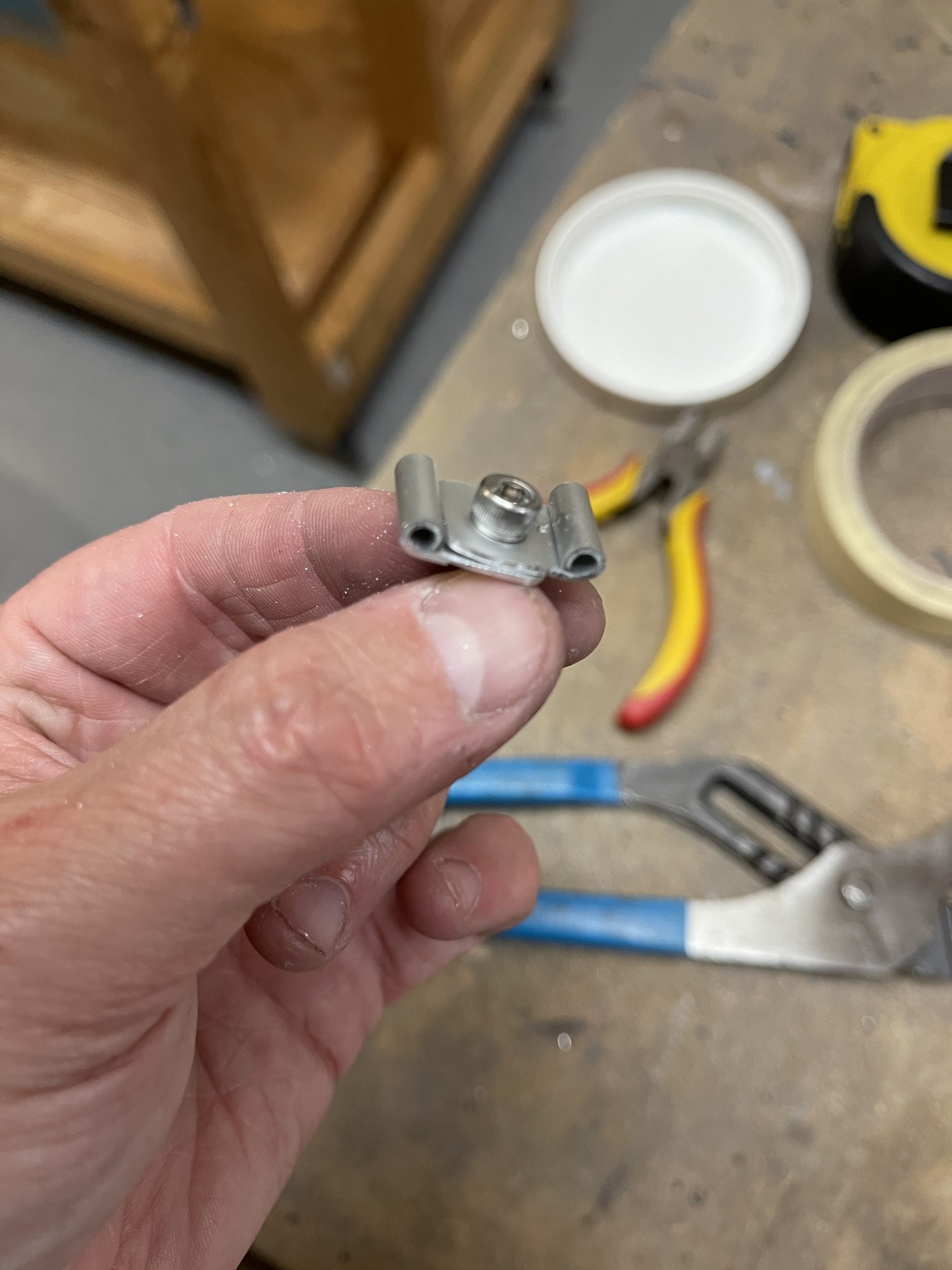
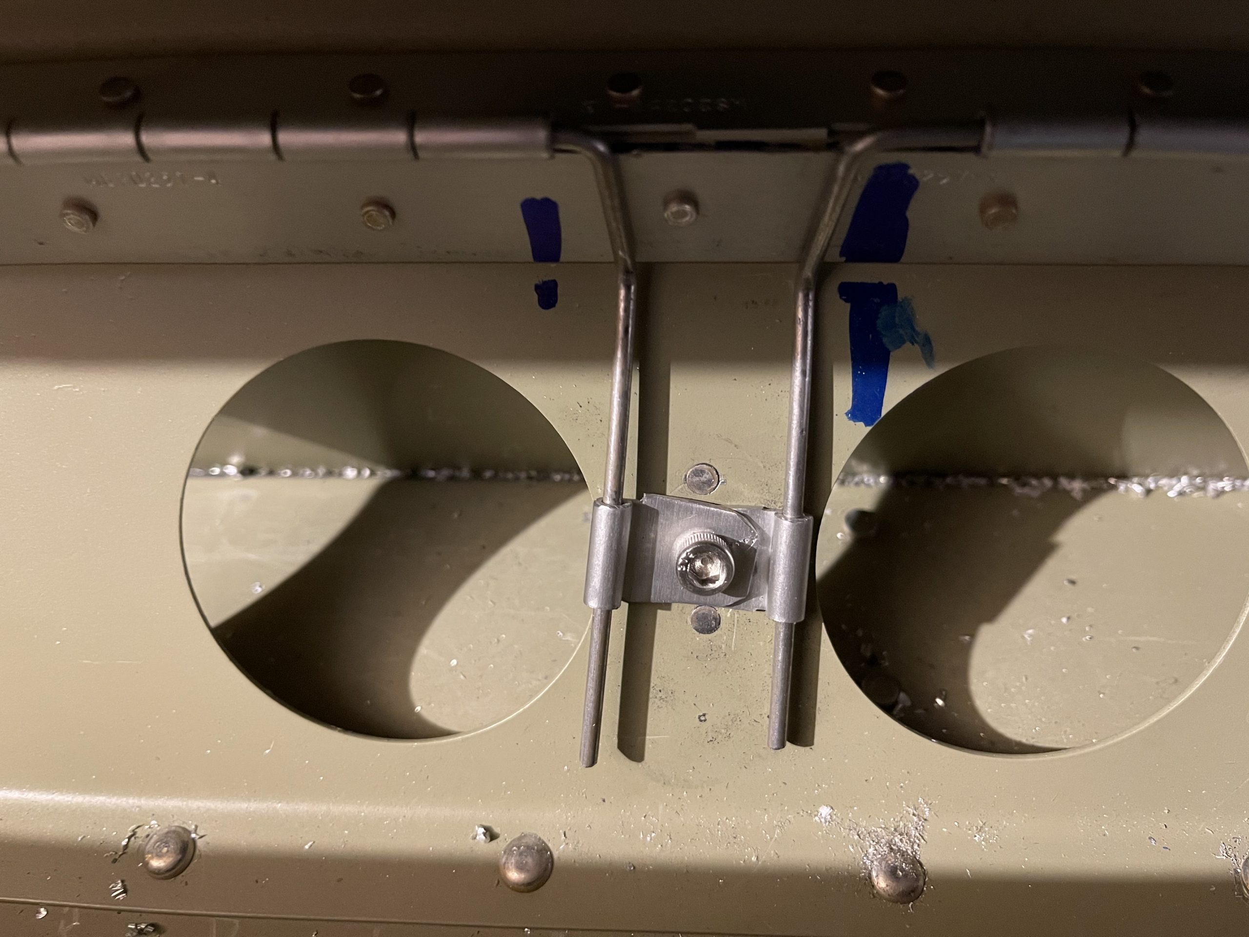
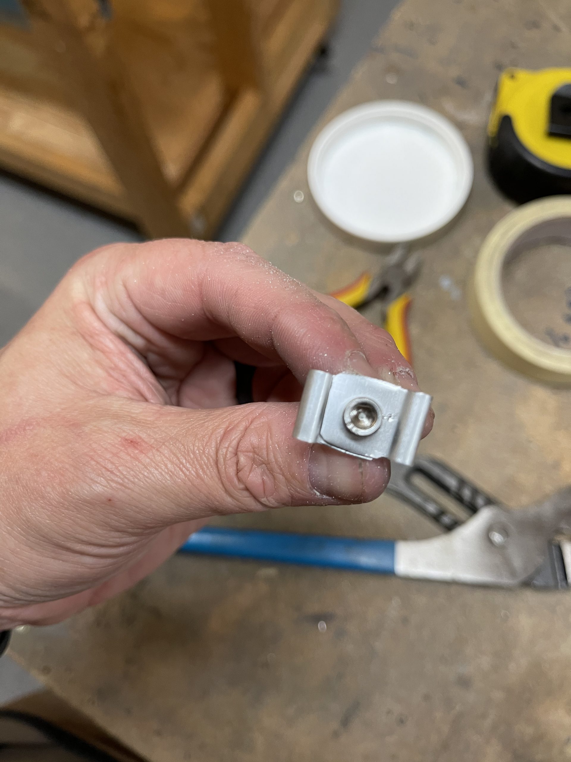
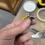
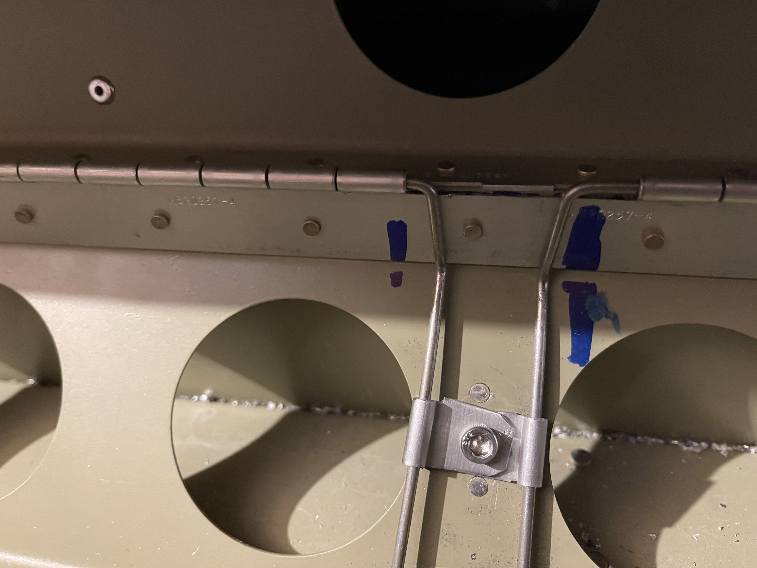
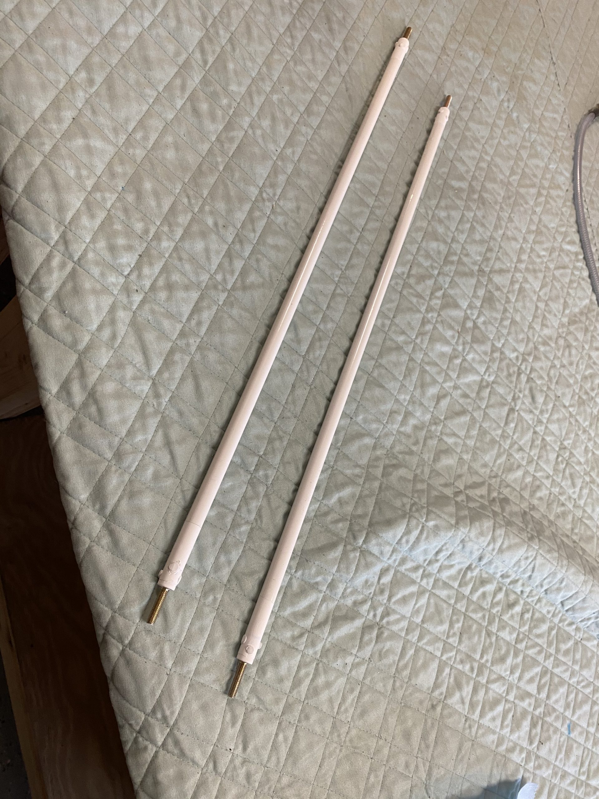
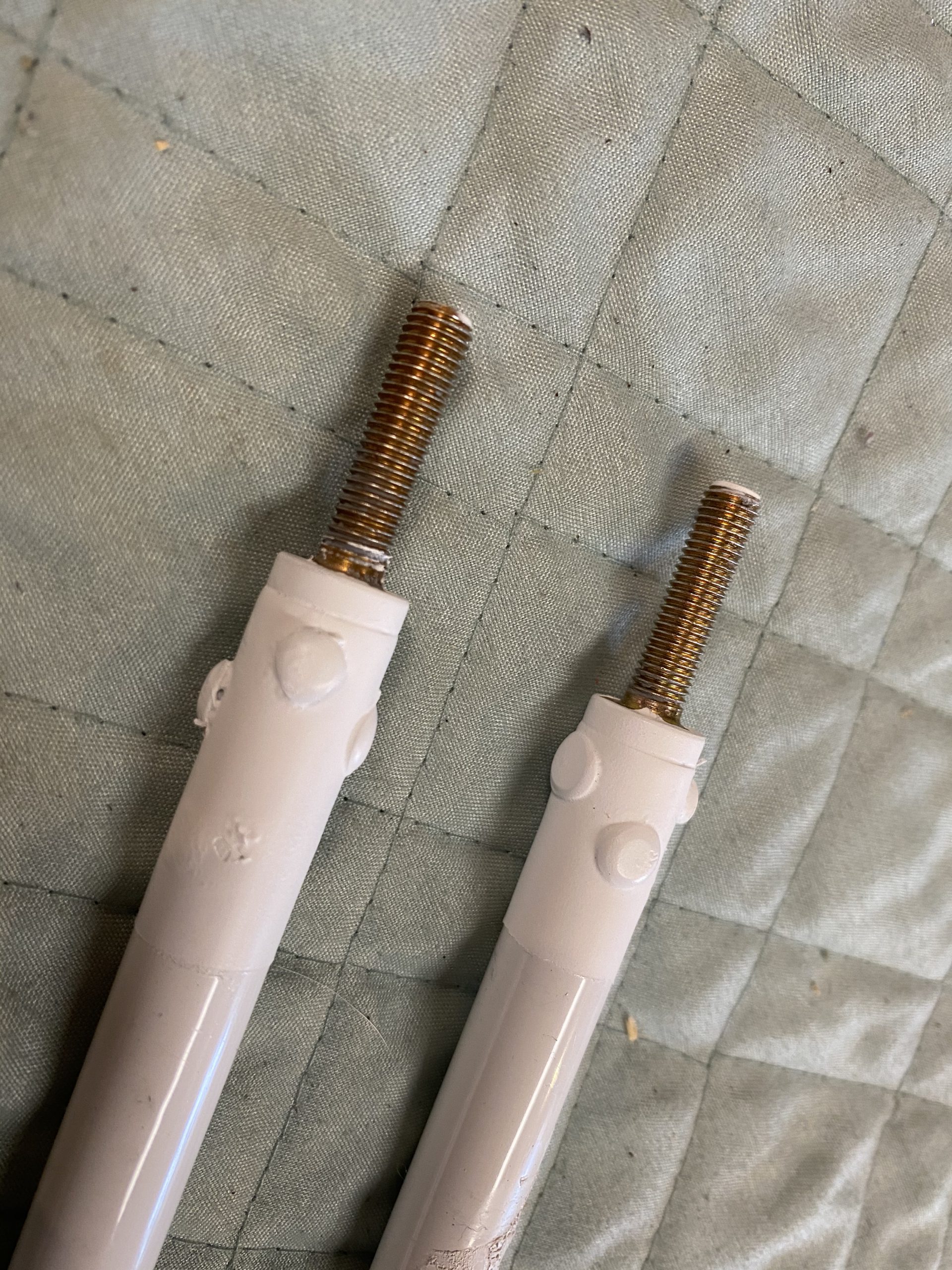
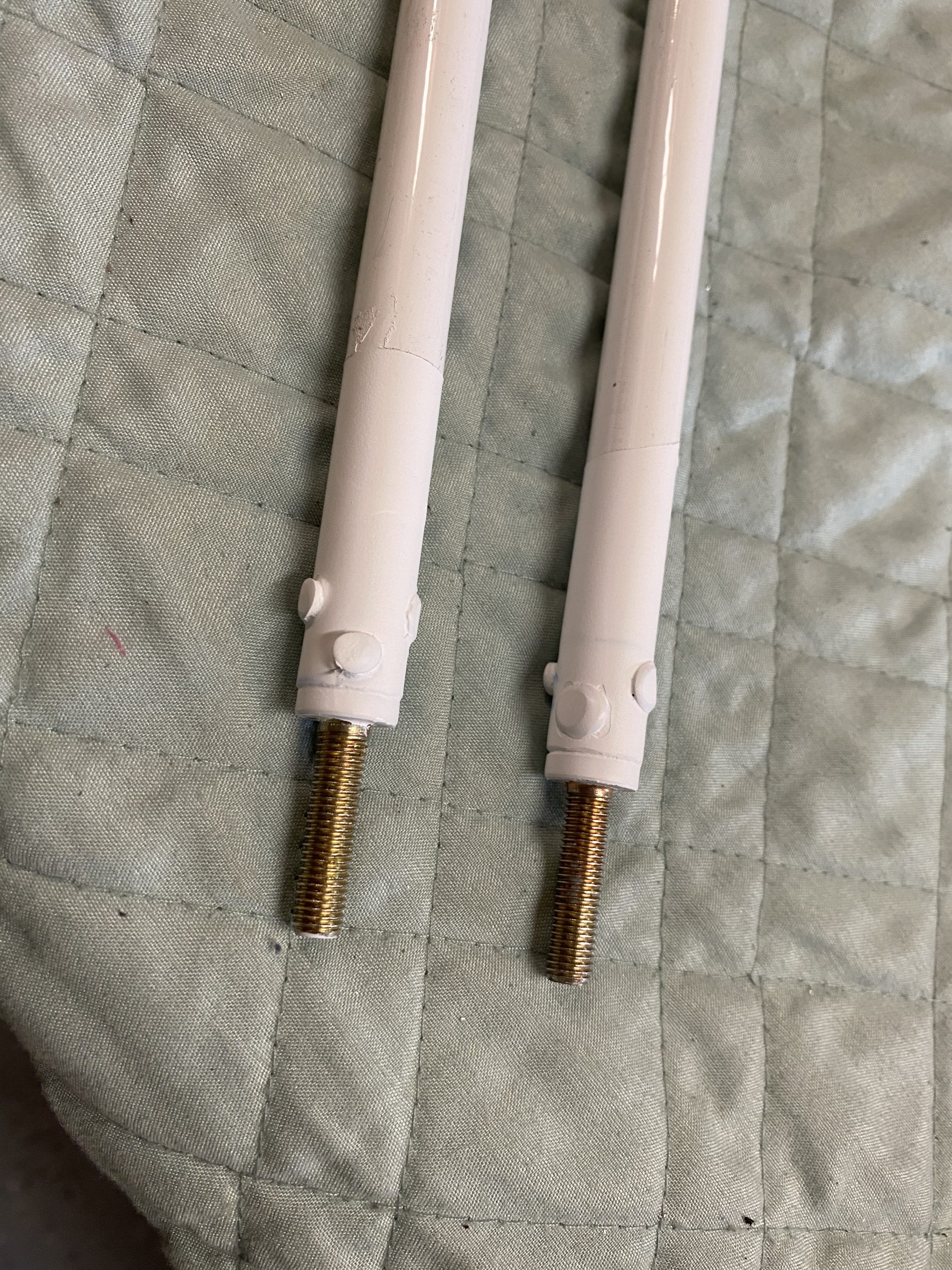
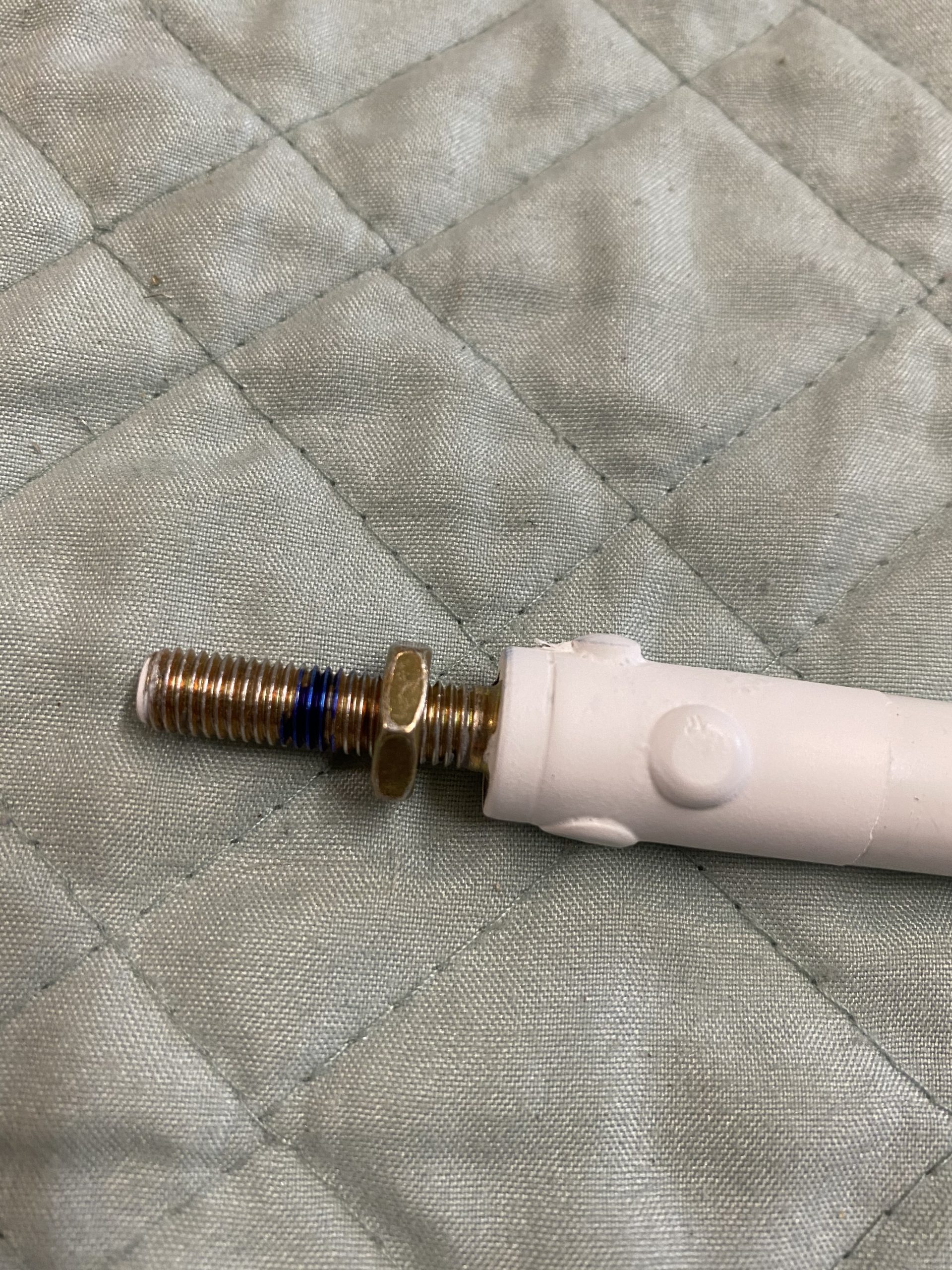
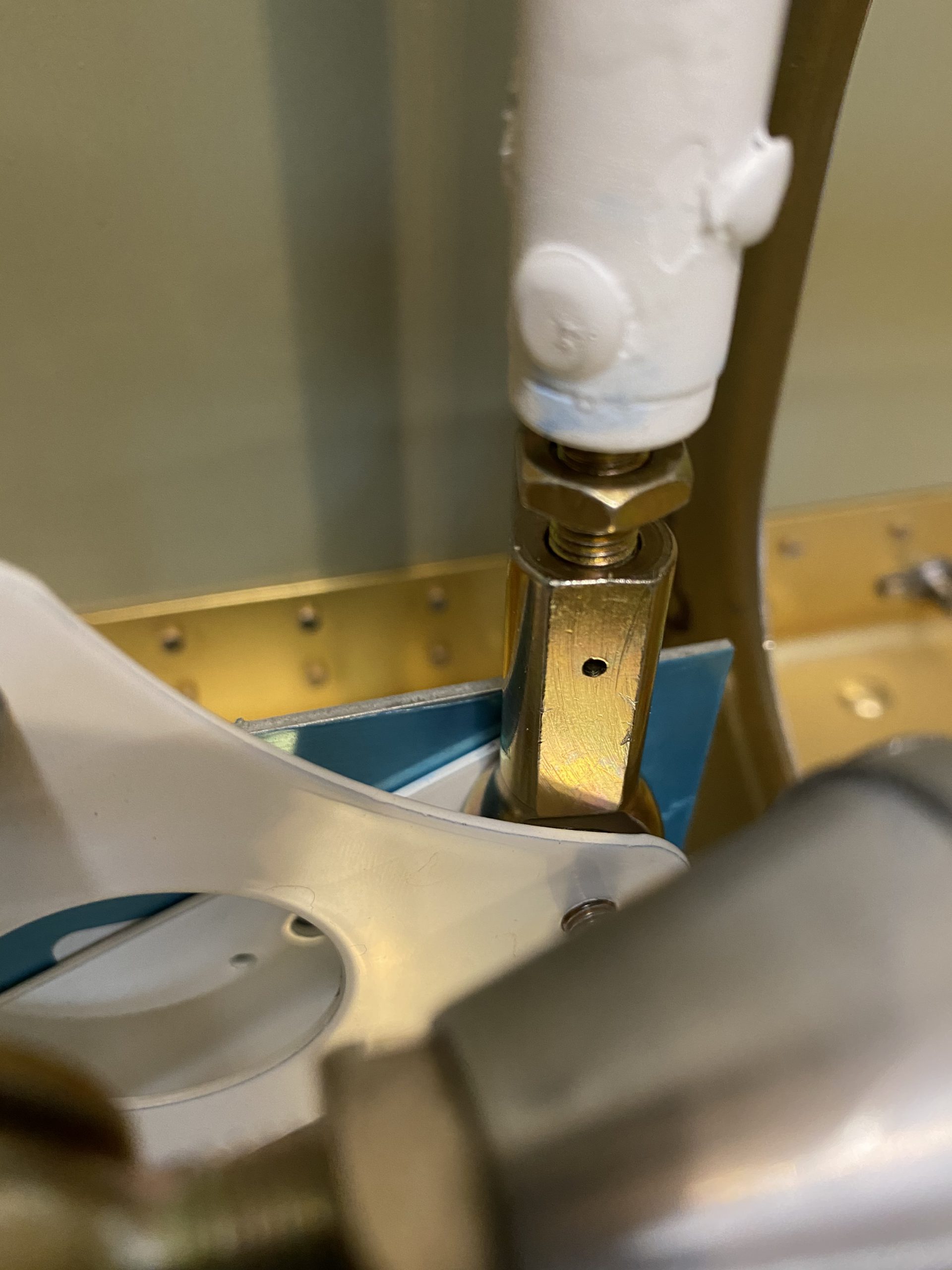
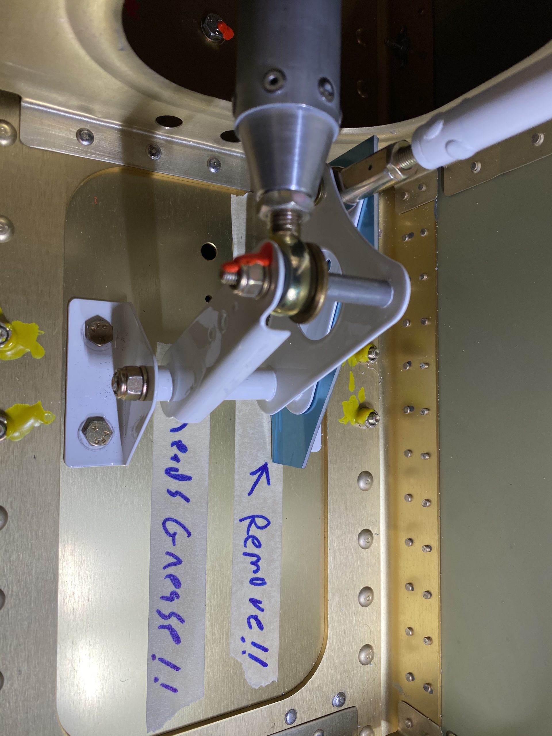
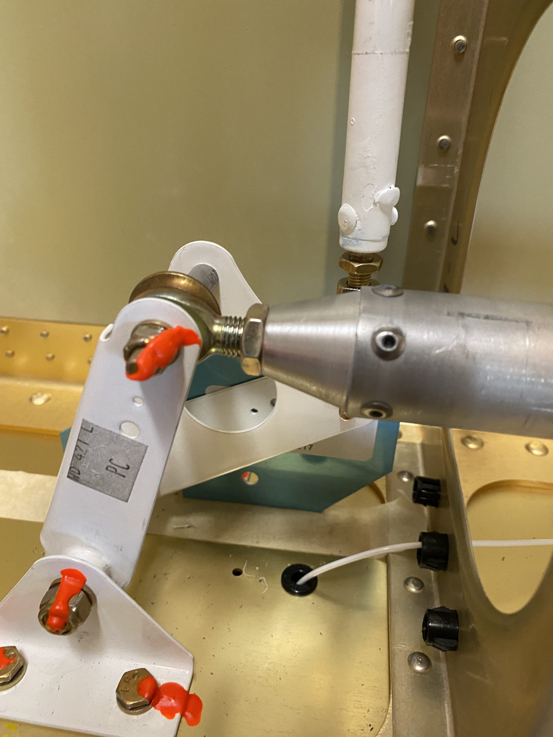
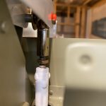
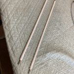
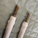
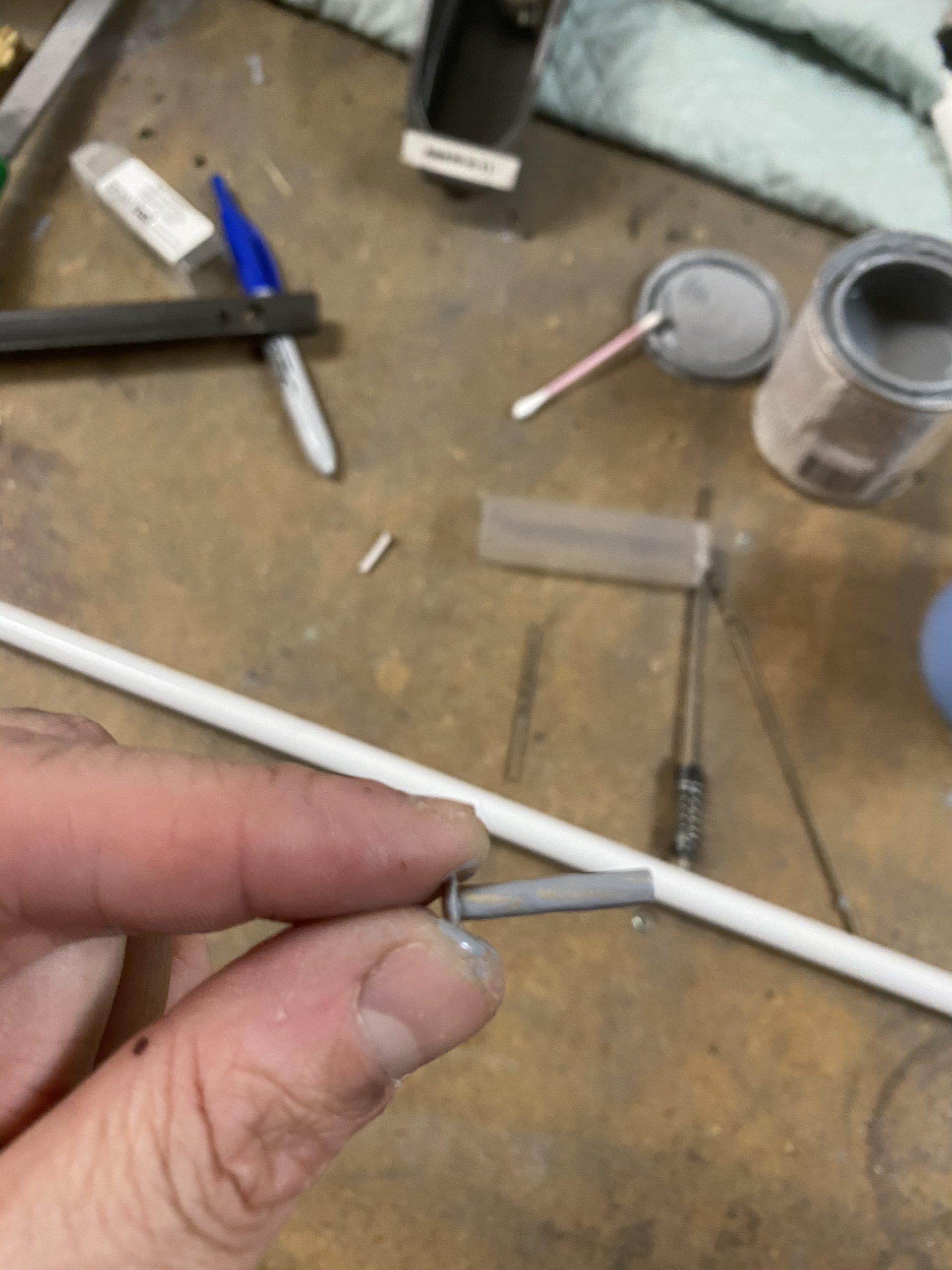
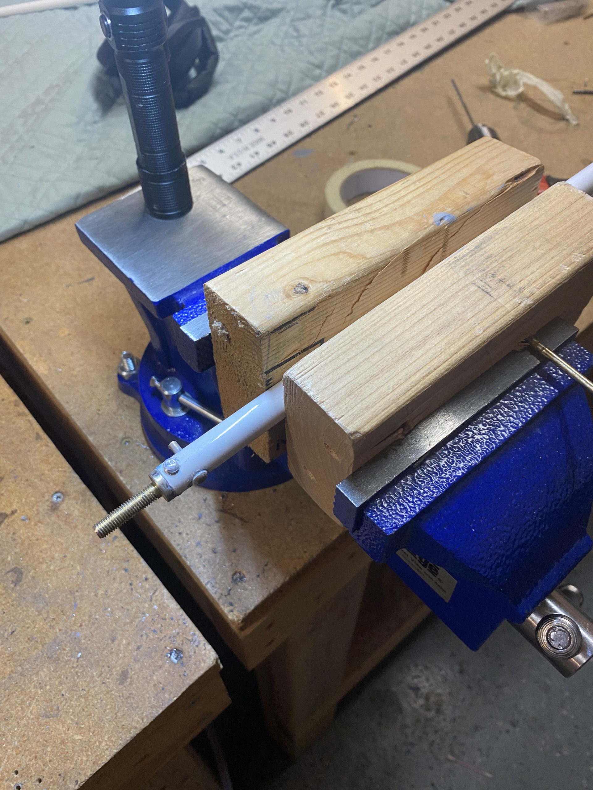
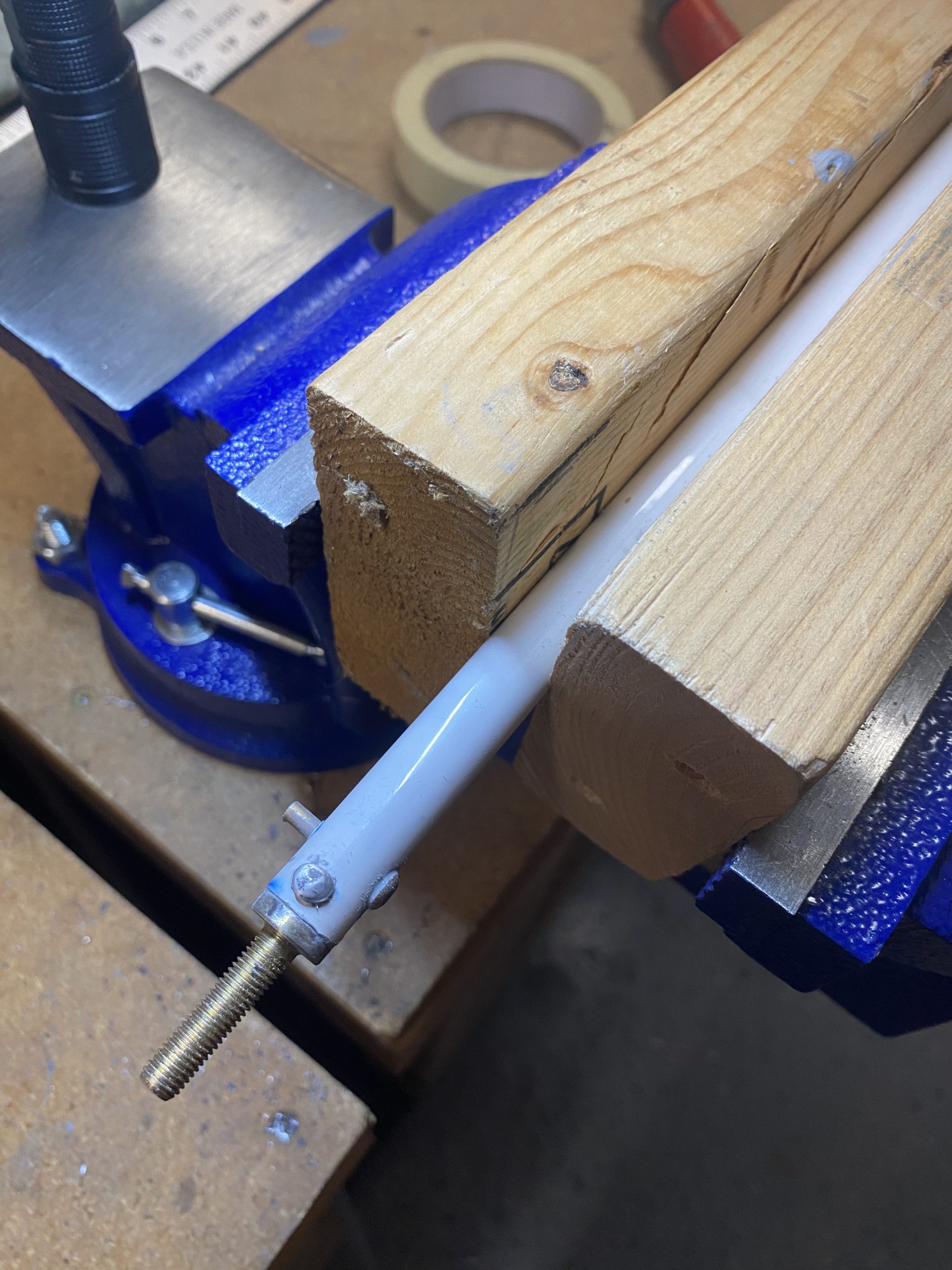
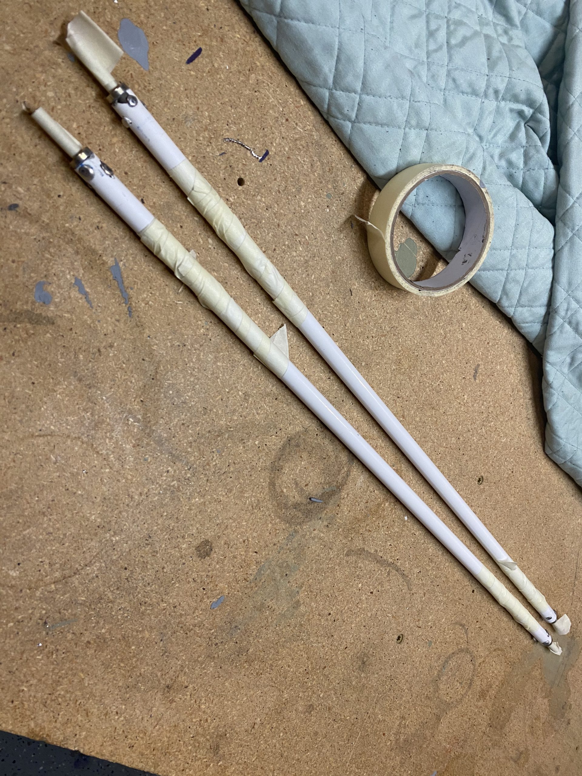
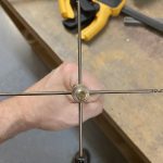
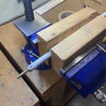
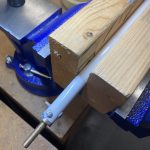
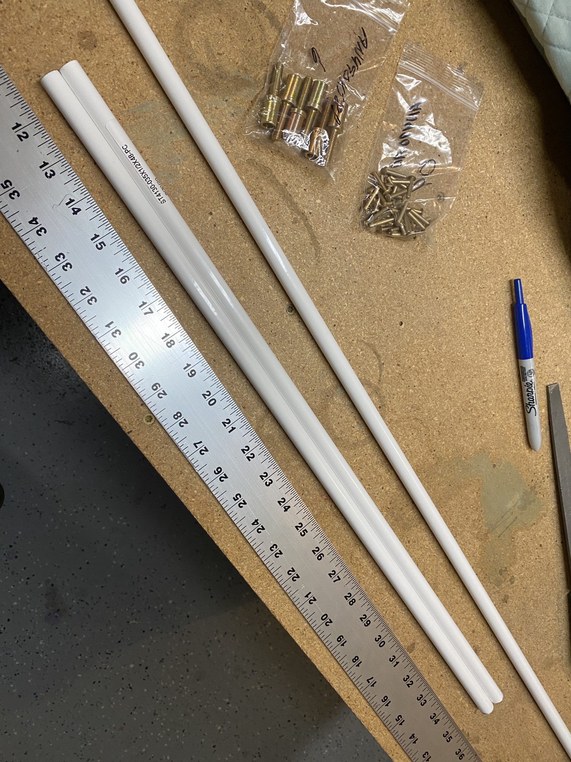
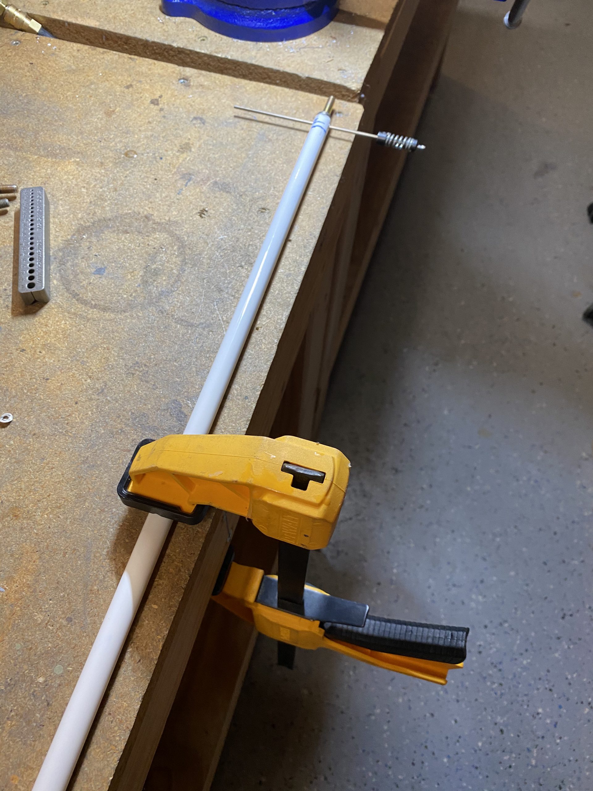
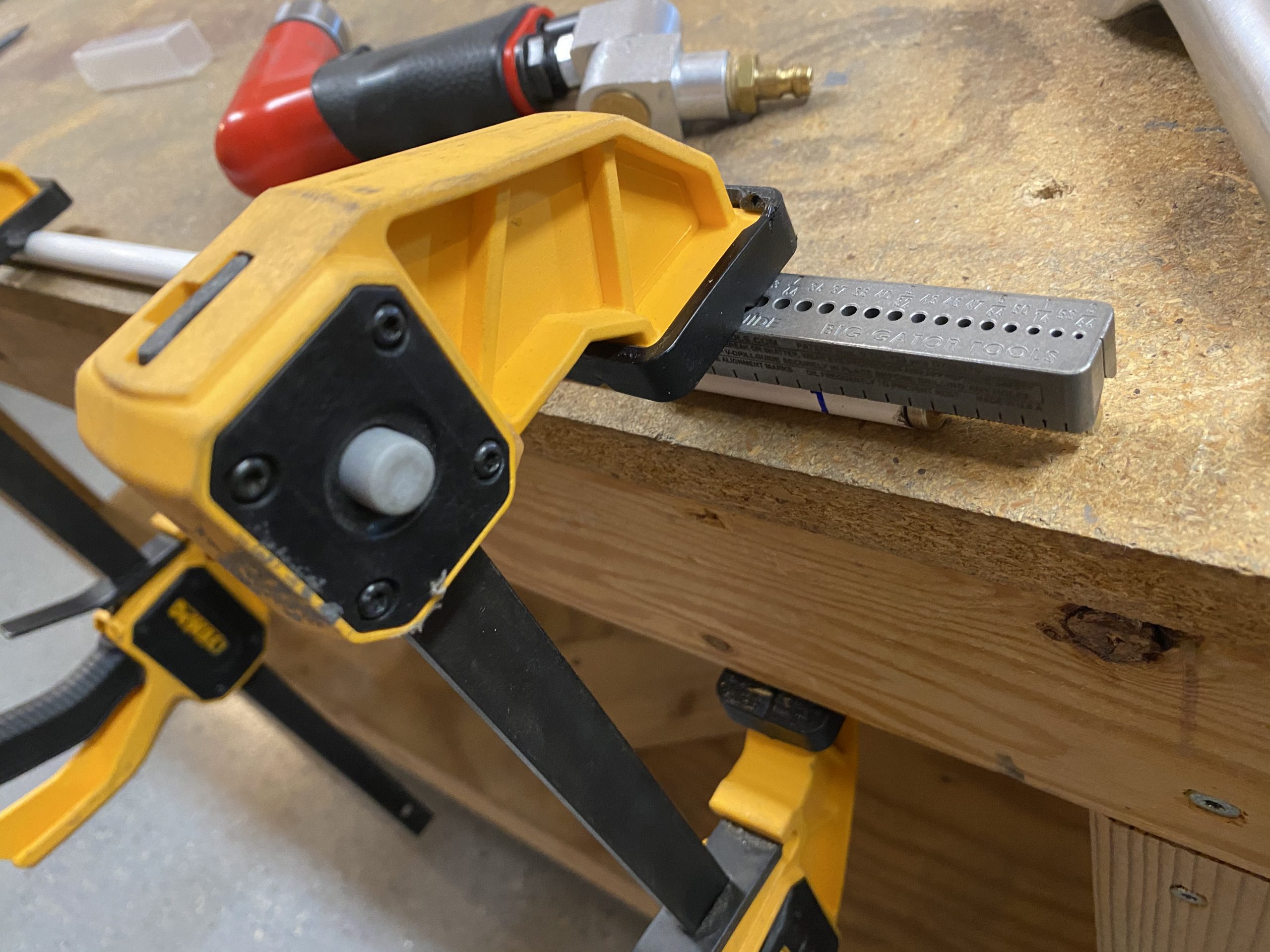
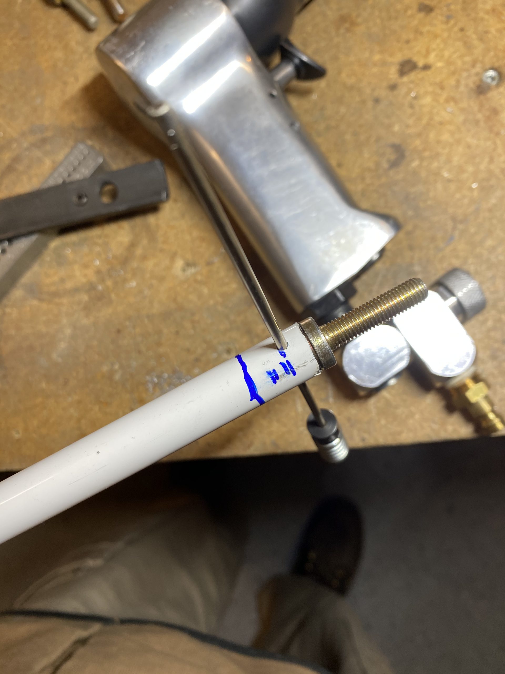
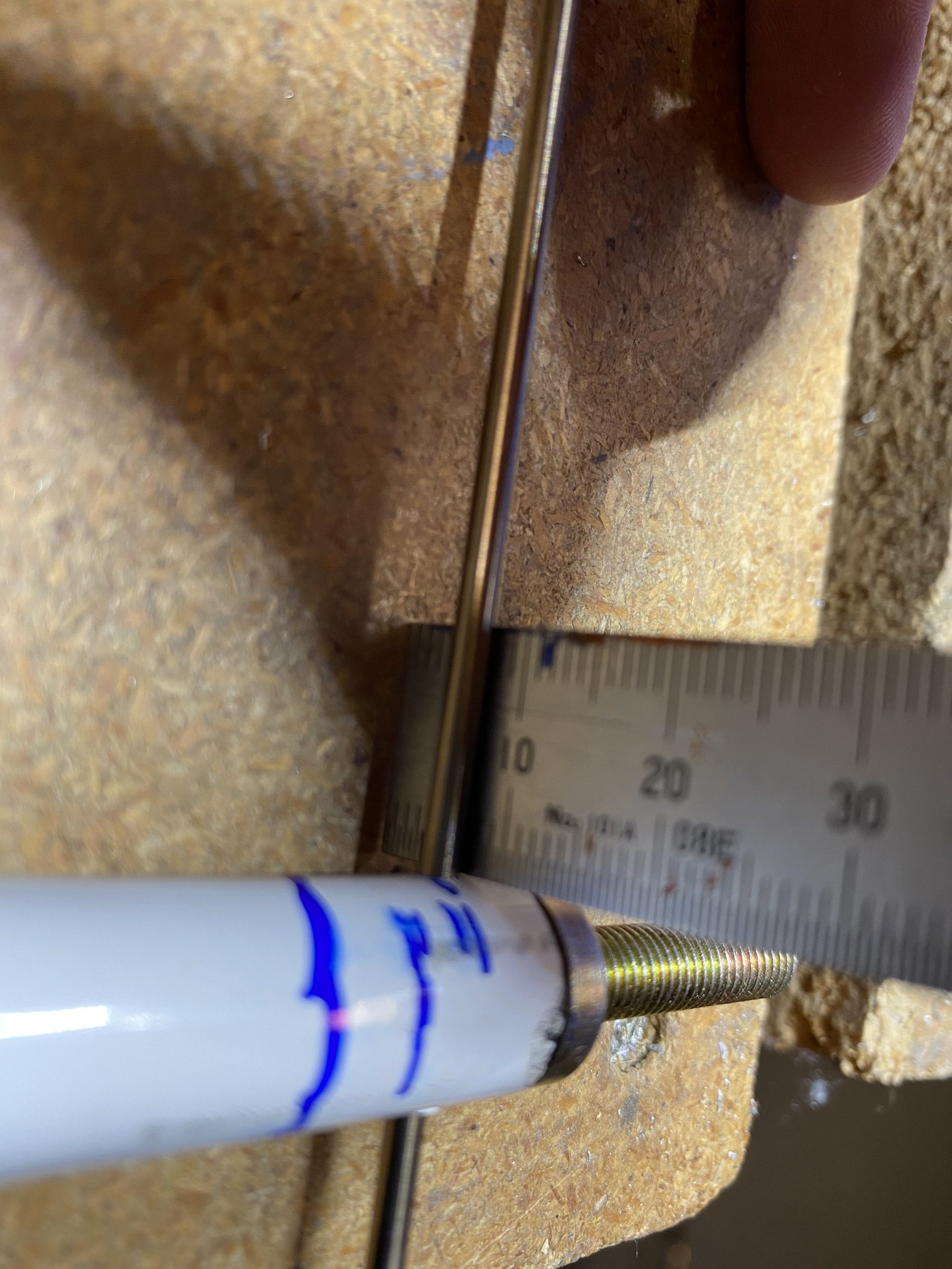
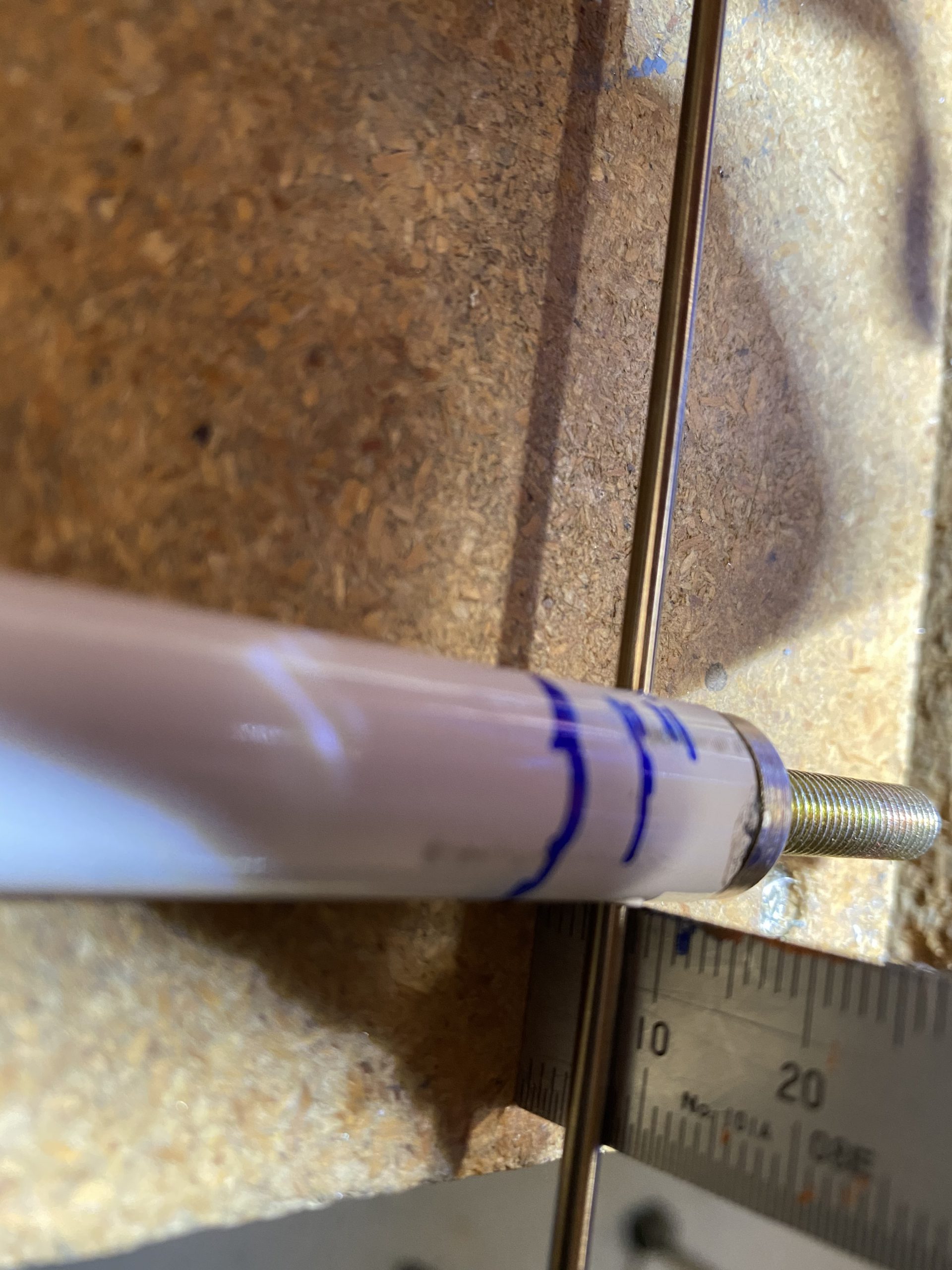
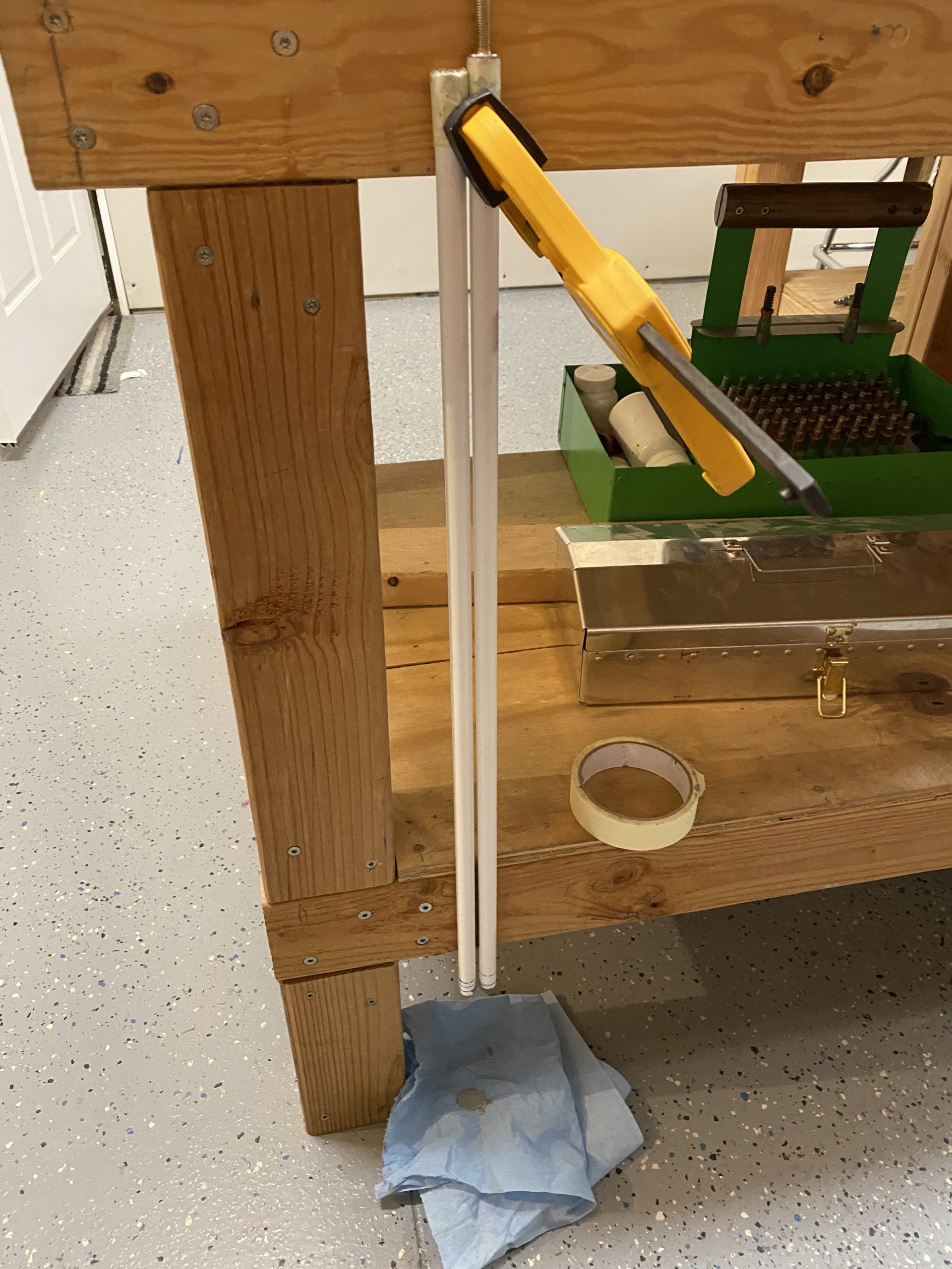
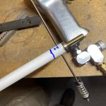
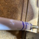
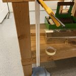
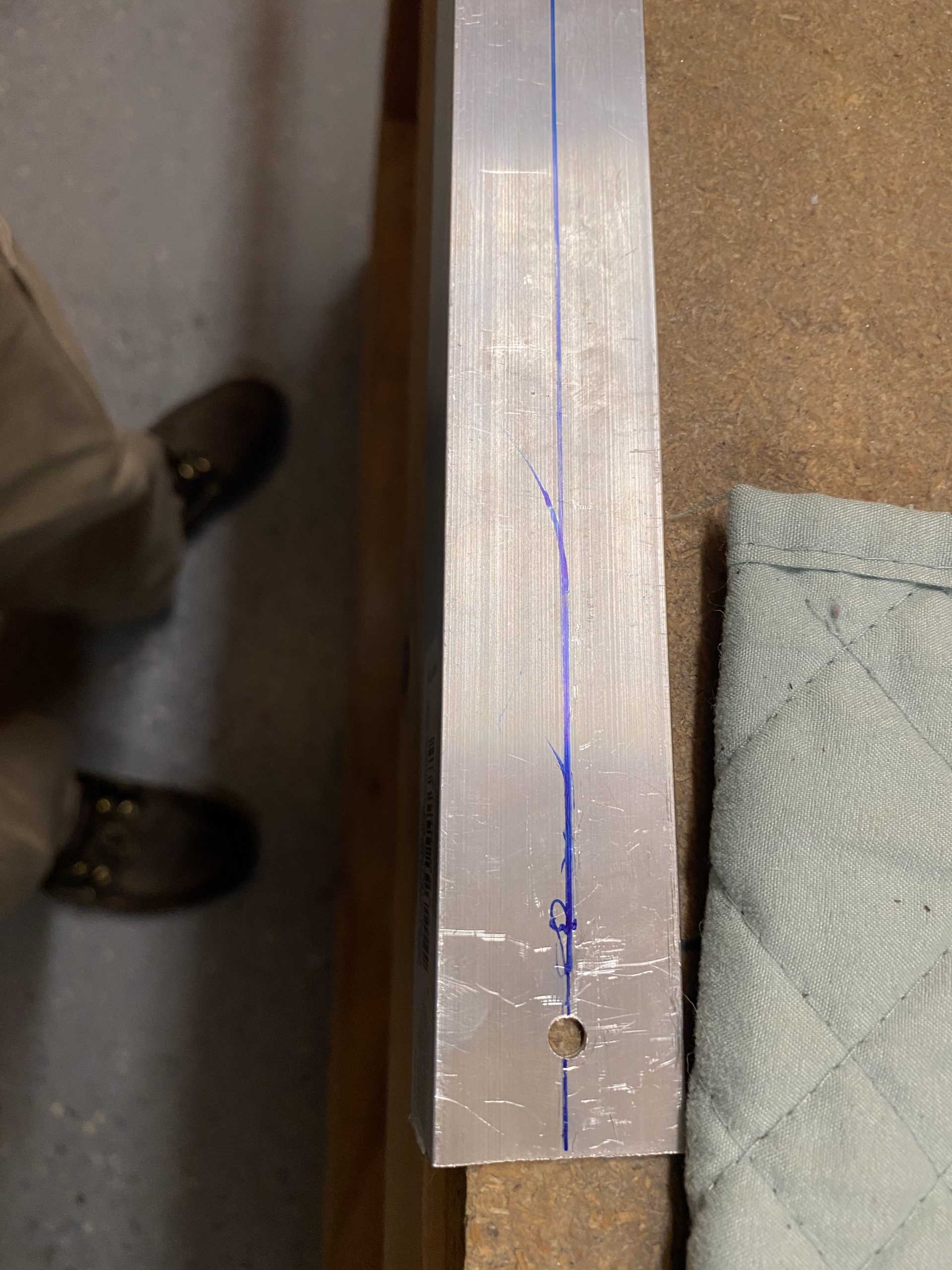
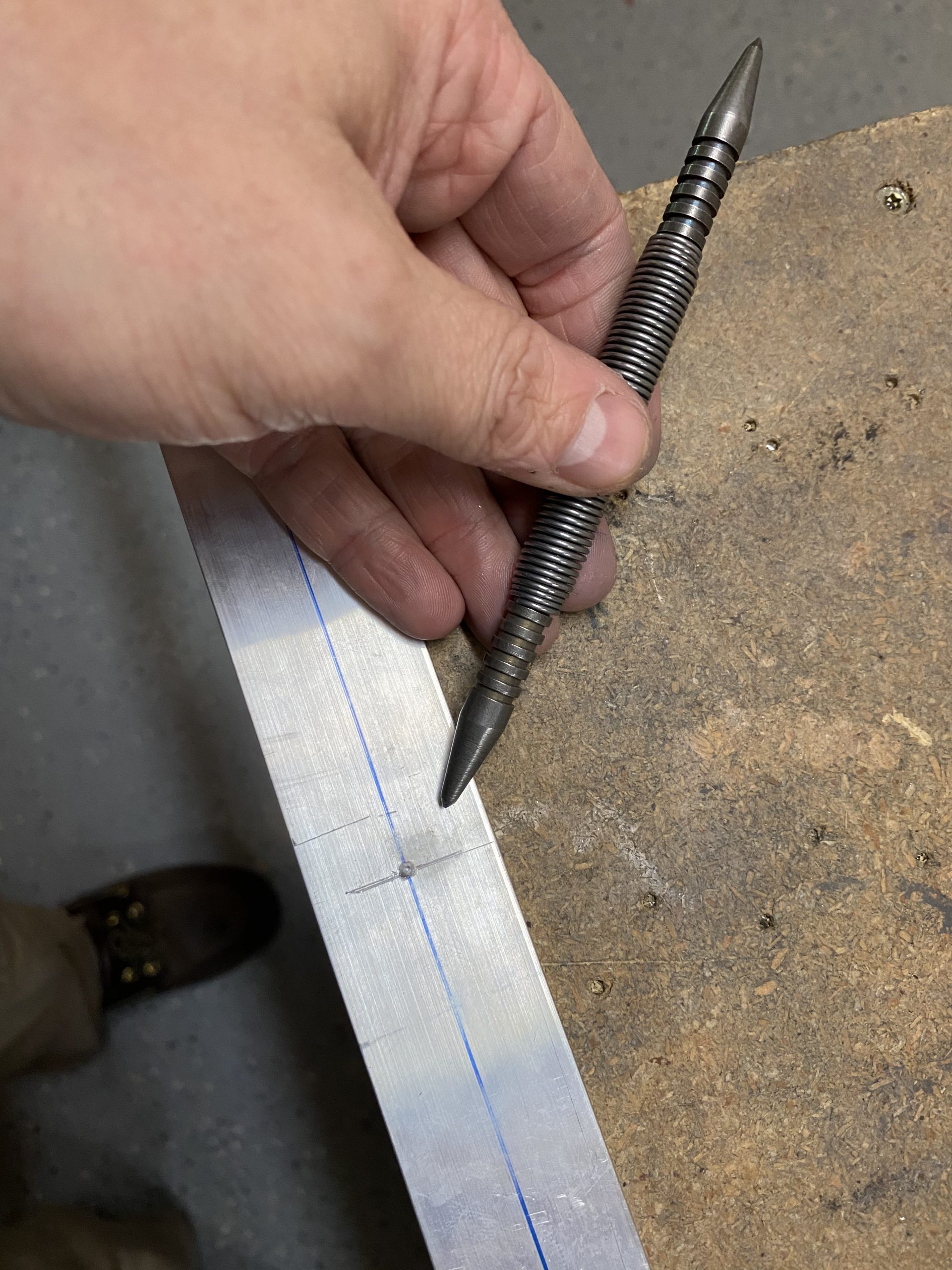
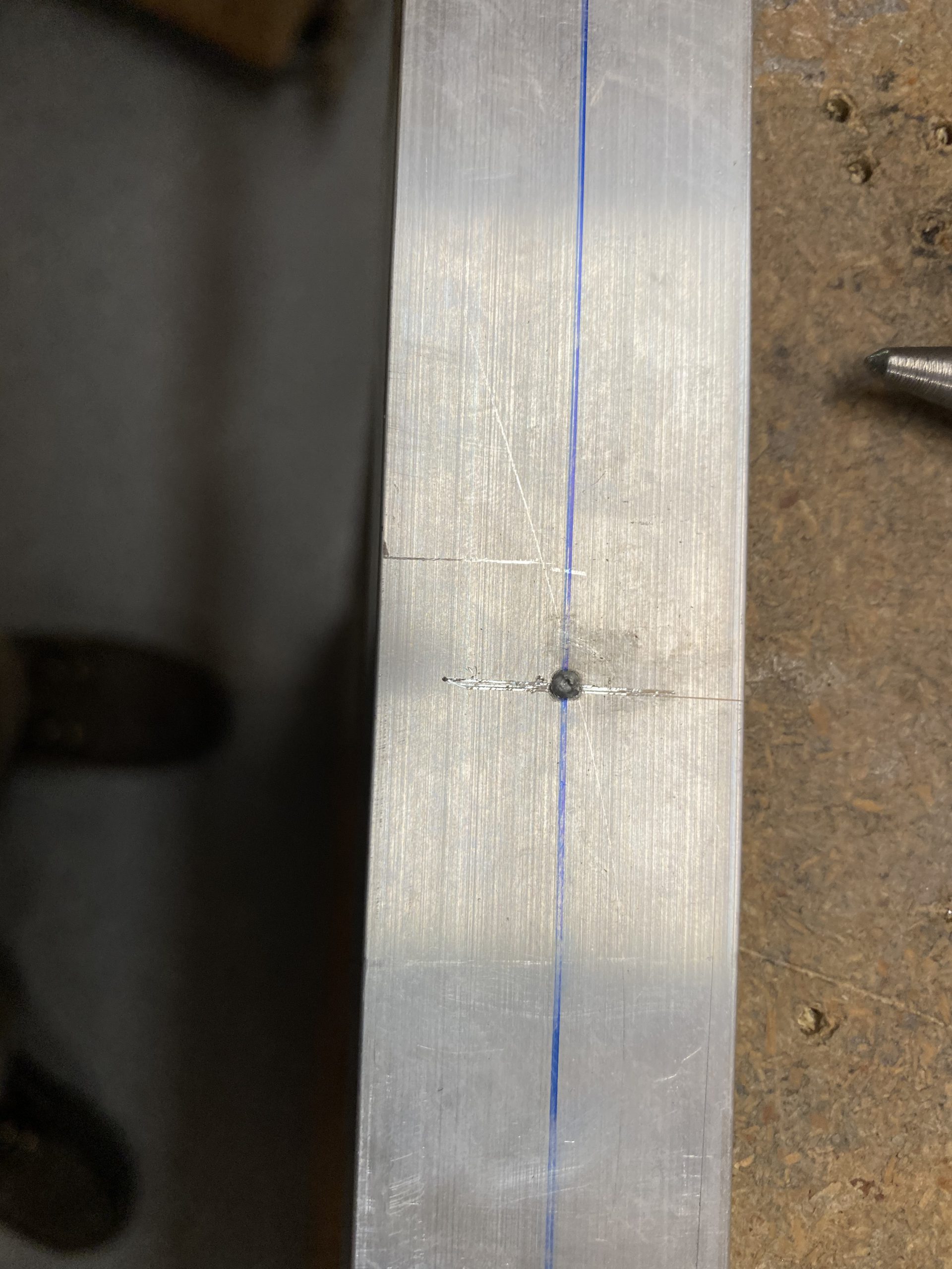
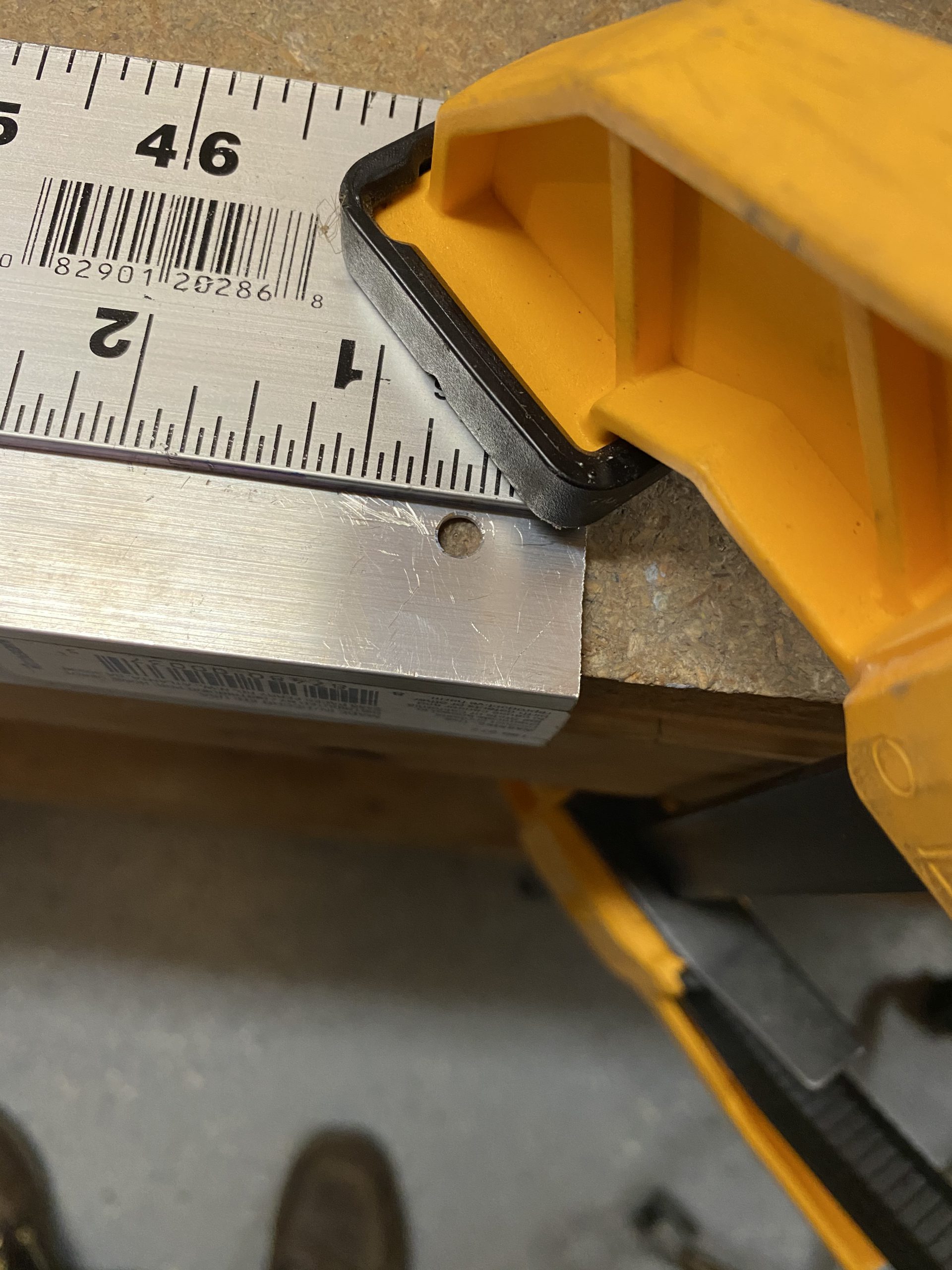
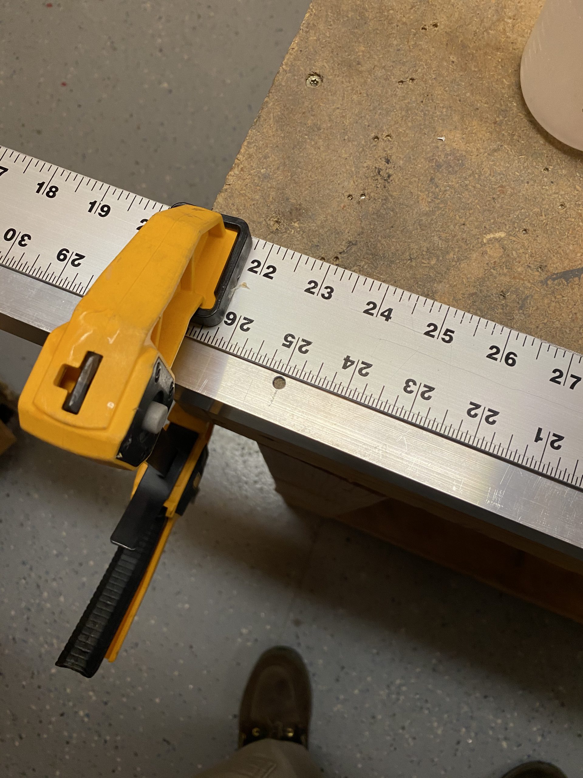
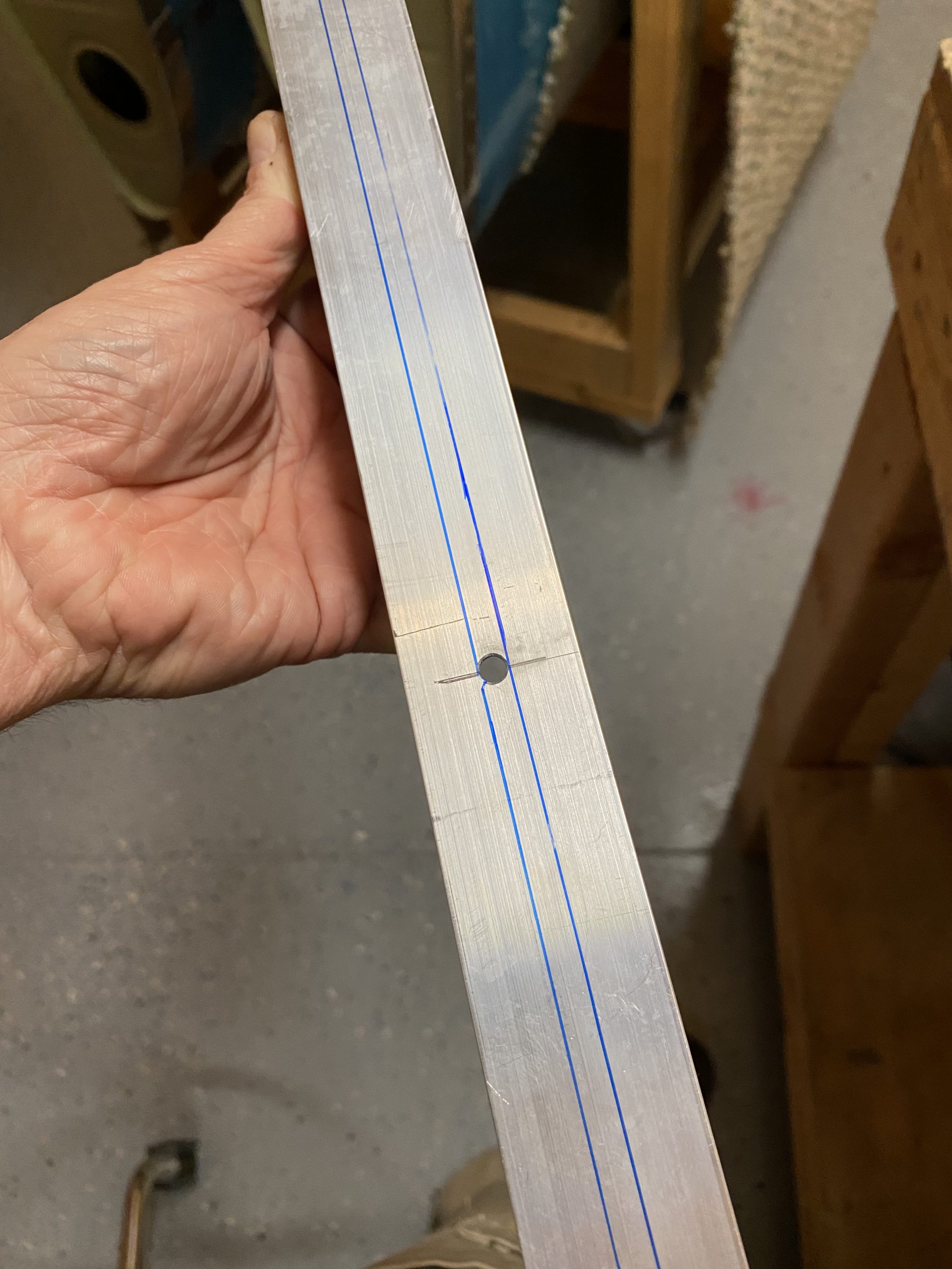
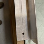
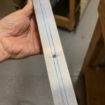
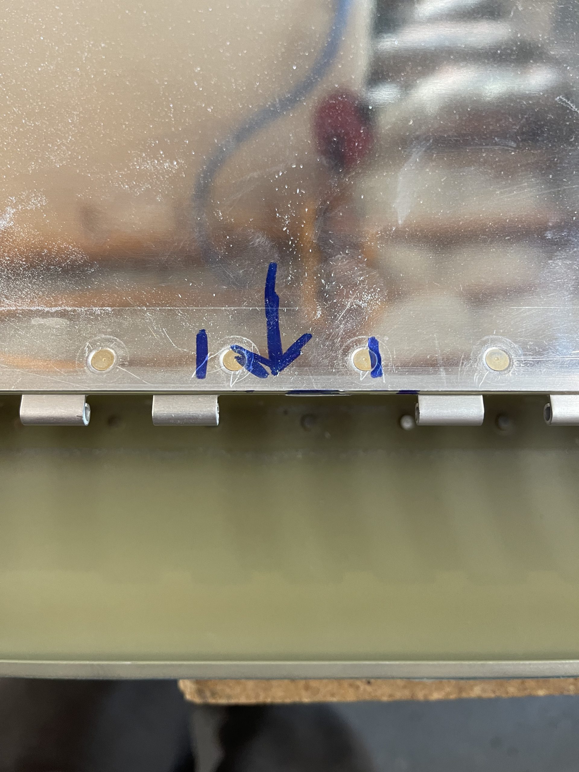
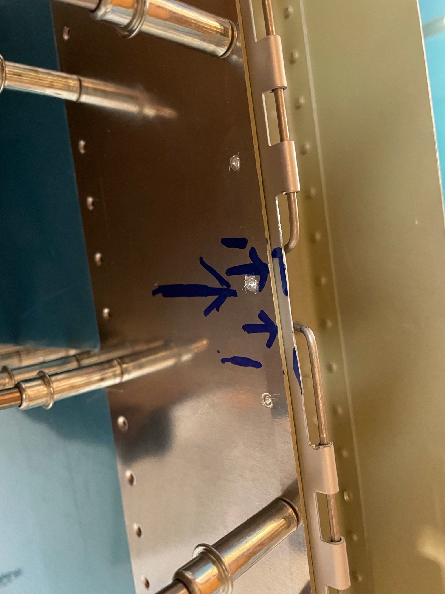
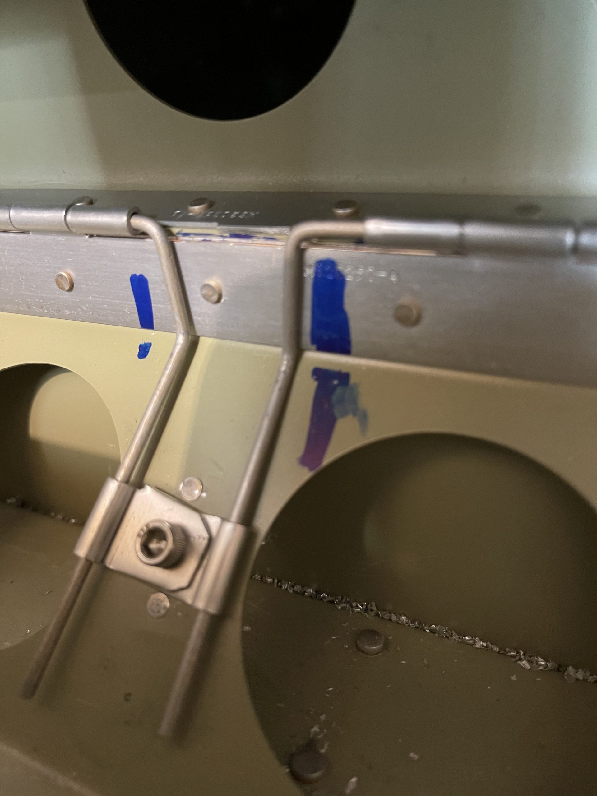
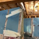
https://www.dracisneros.com/?p=1988 I had one last order of business, and that was to cut and bend the hinge pin so that it would fit nicely in the center and reach the pin holders I made in the last session. I measure my pins, cut them to length and then set off bending them to the proper shape to fit down against the flap brace, where I installed the holders for them. This is where I marked them, and started the bending.
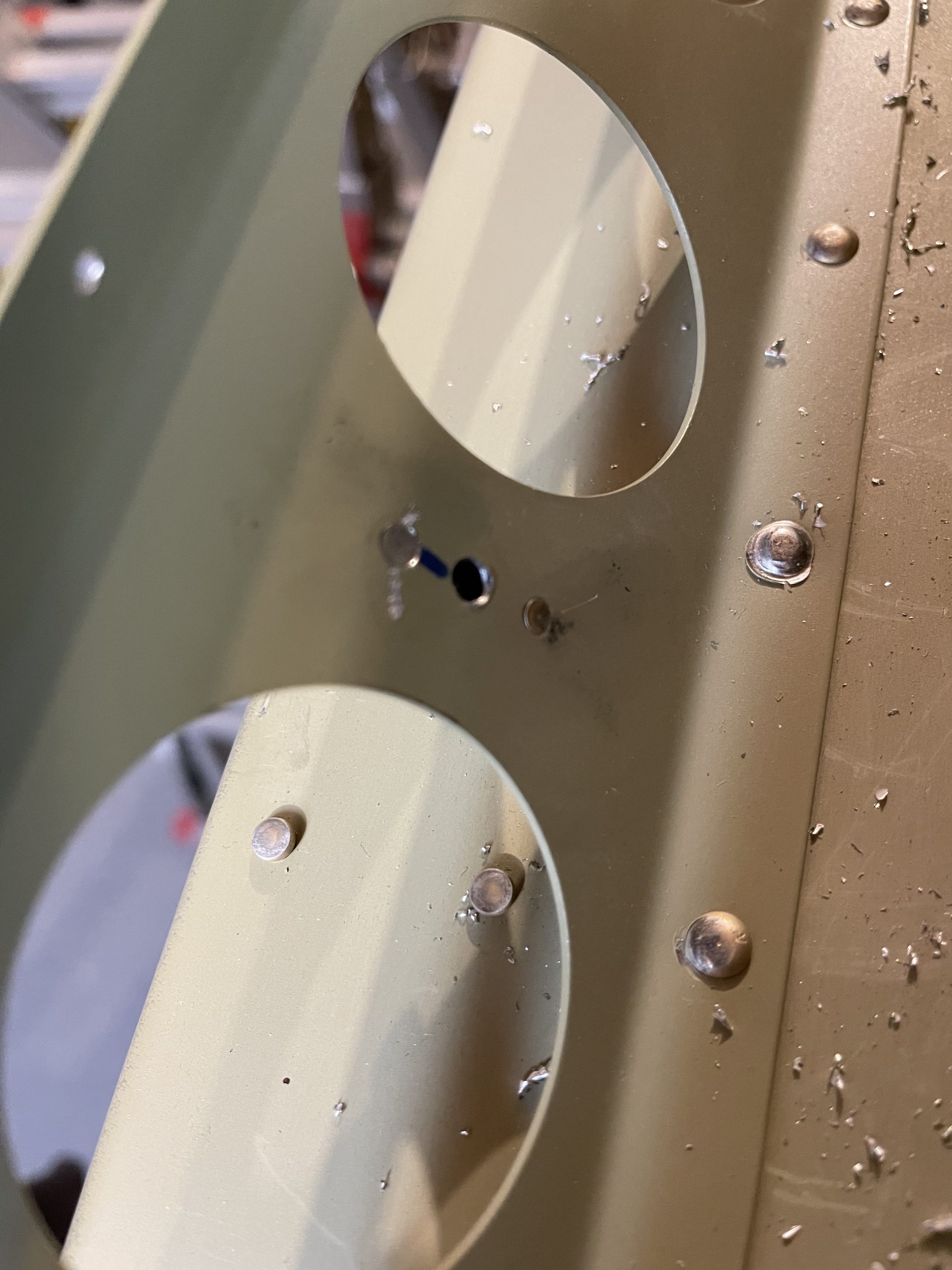
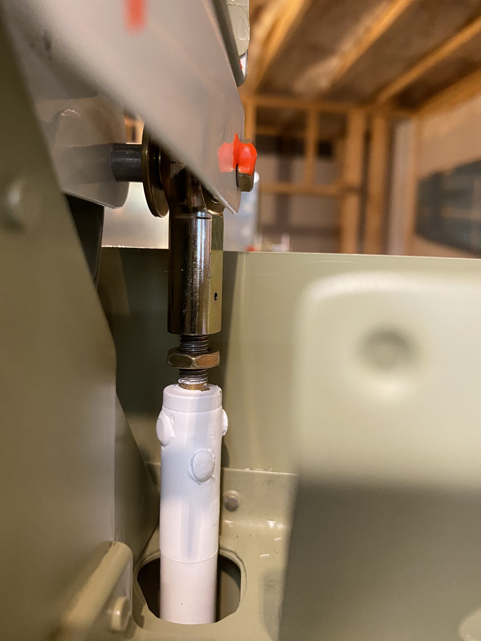
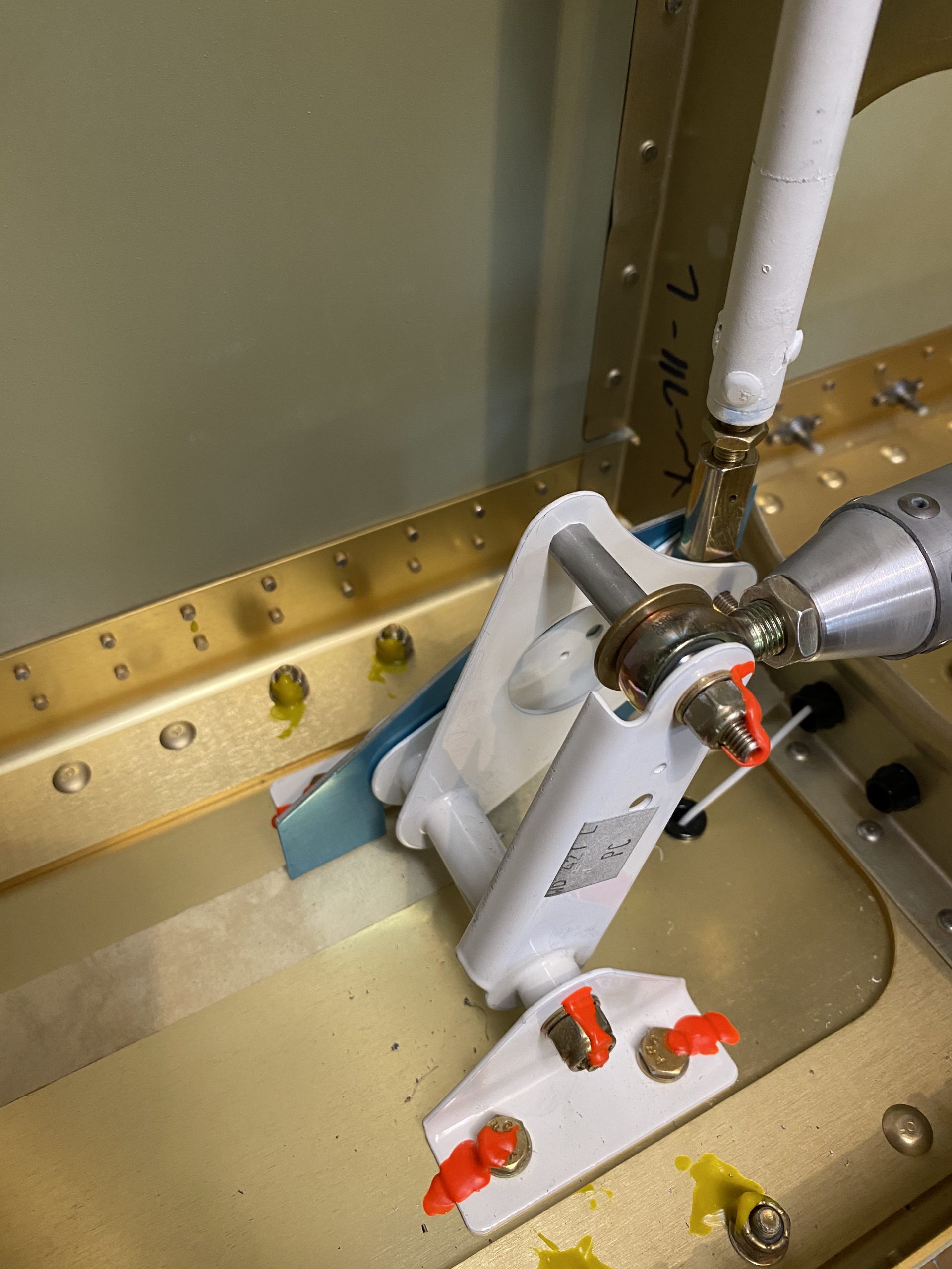
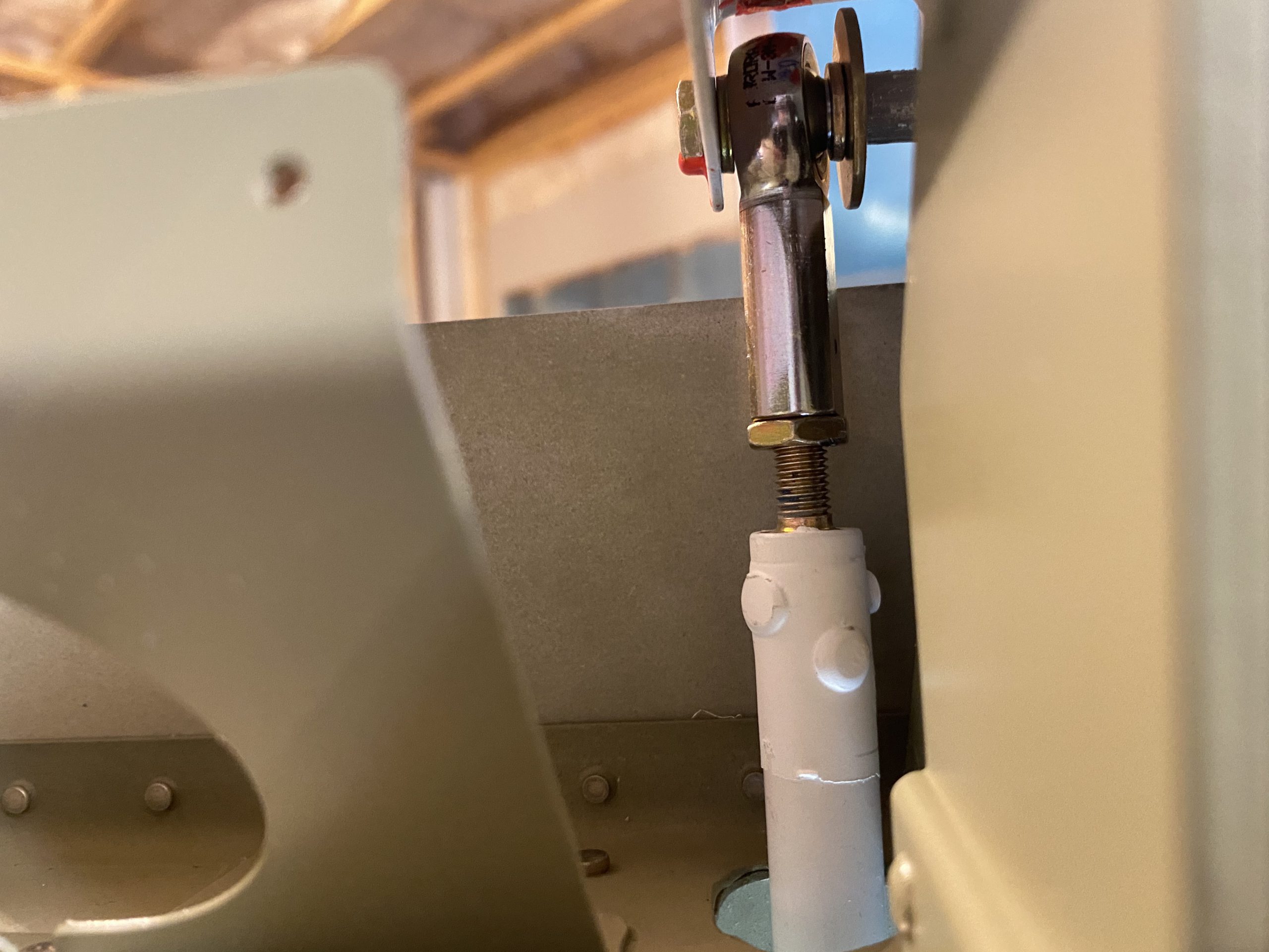
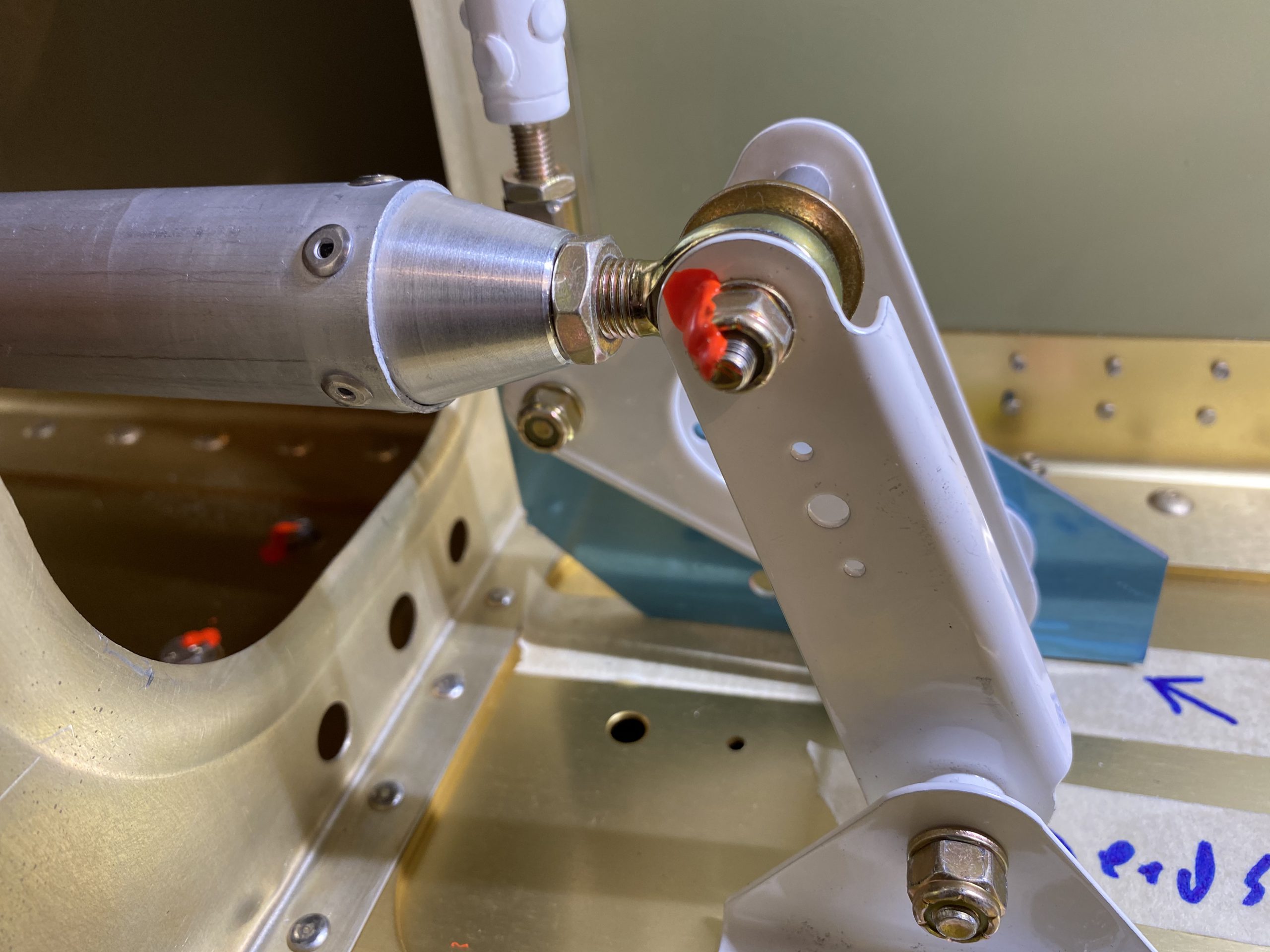
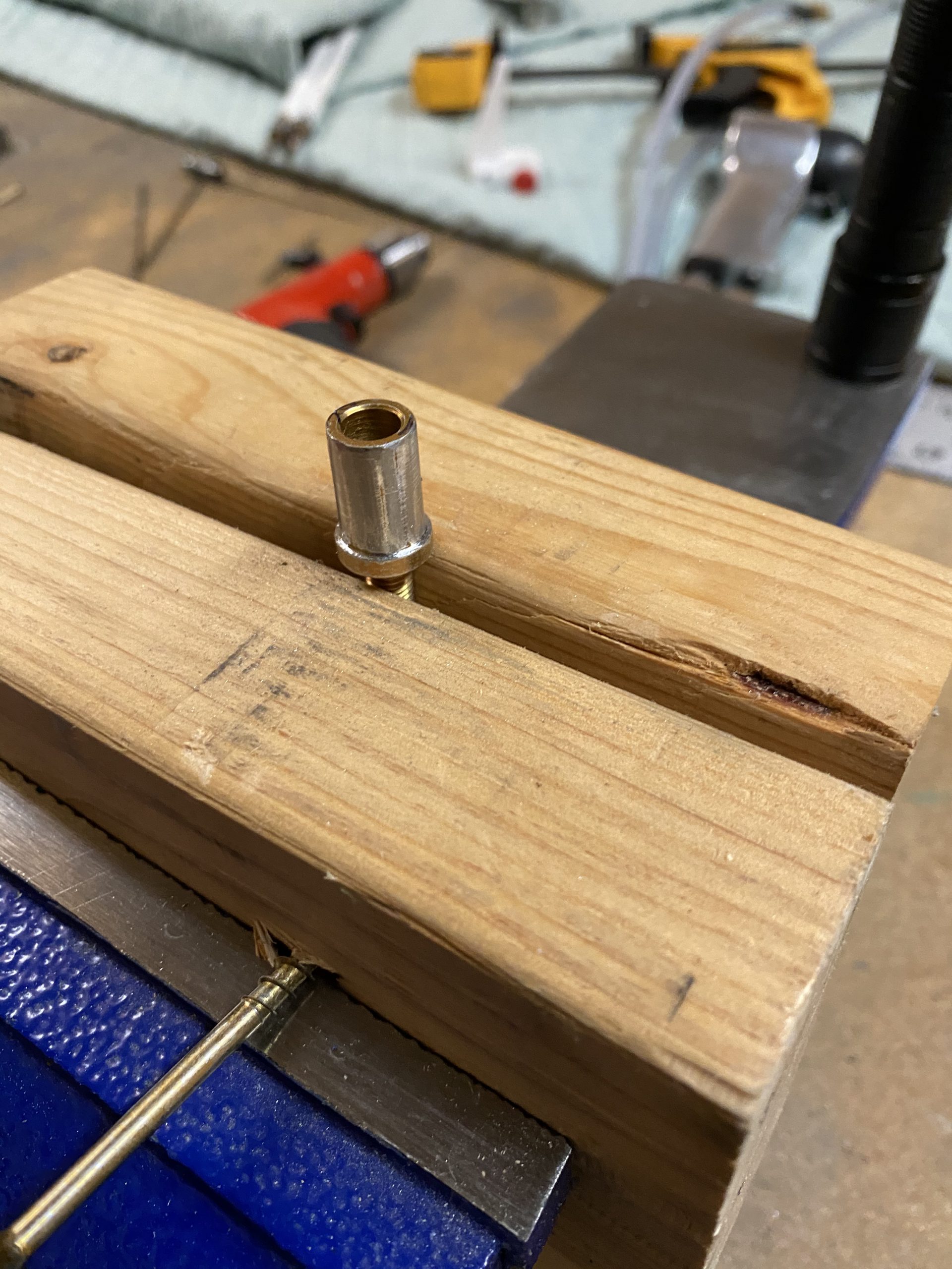
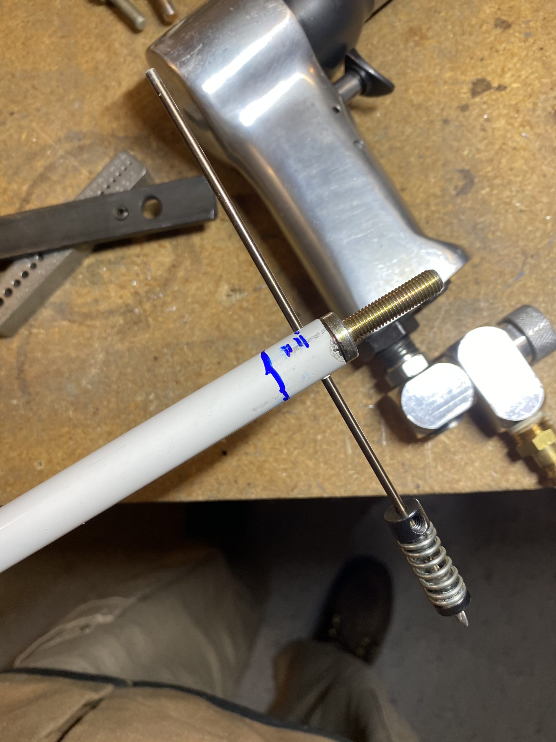
https://elien.ca/hfd0op99qjz And with a little more work, I had them shapped to fit nicely where I installed the holder, about midway down the flap brace.
https://www.doktressmelange.com/2025/06/17/7c7hzmfd64 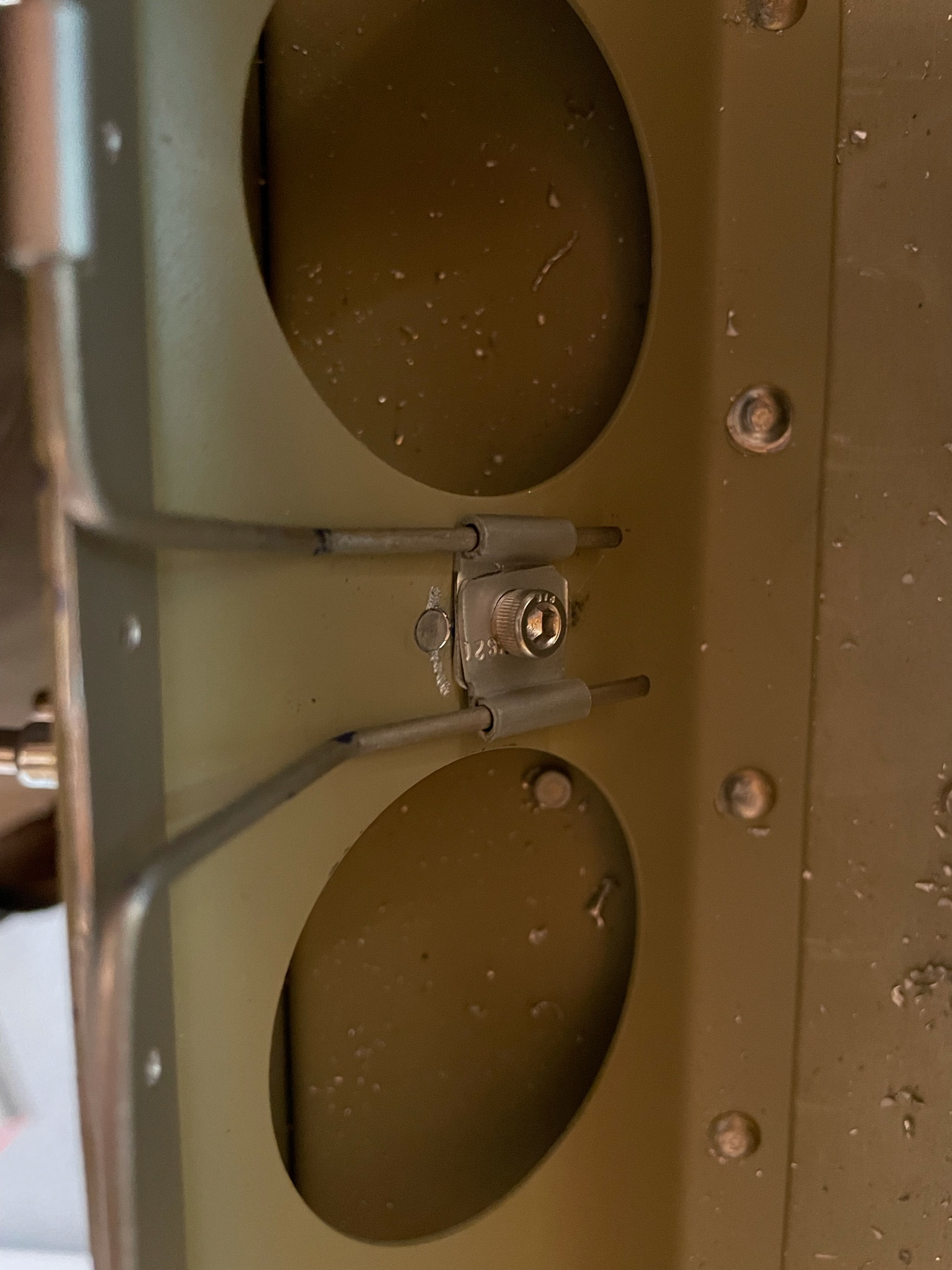
https://www.thevampiresource.com/p0silvi0 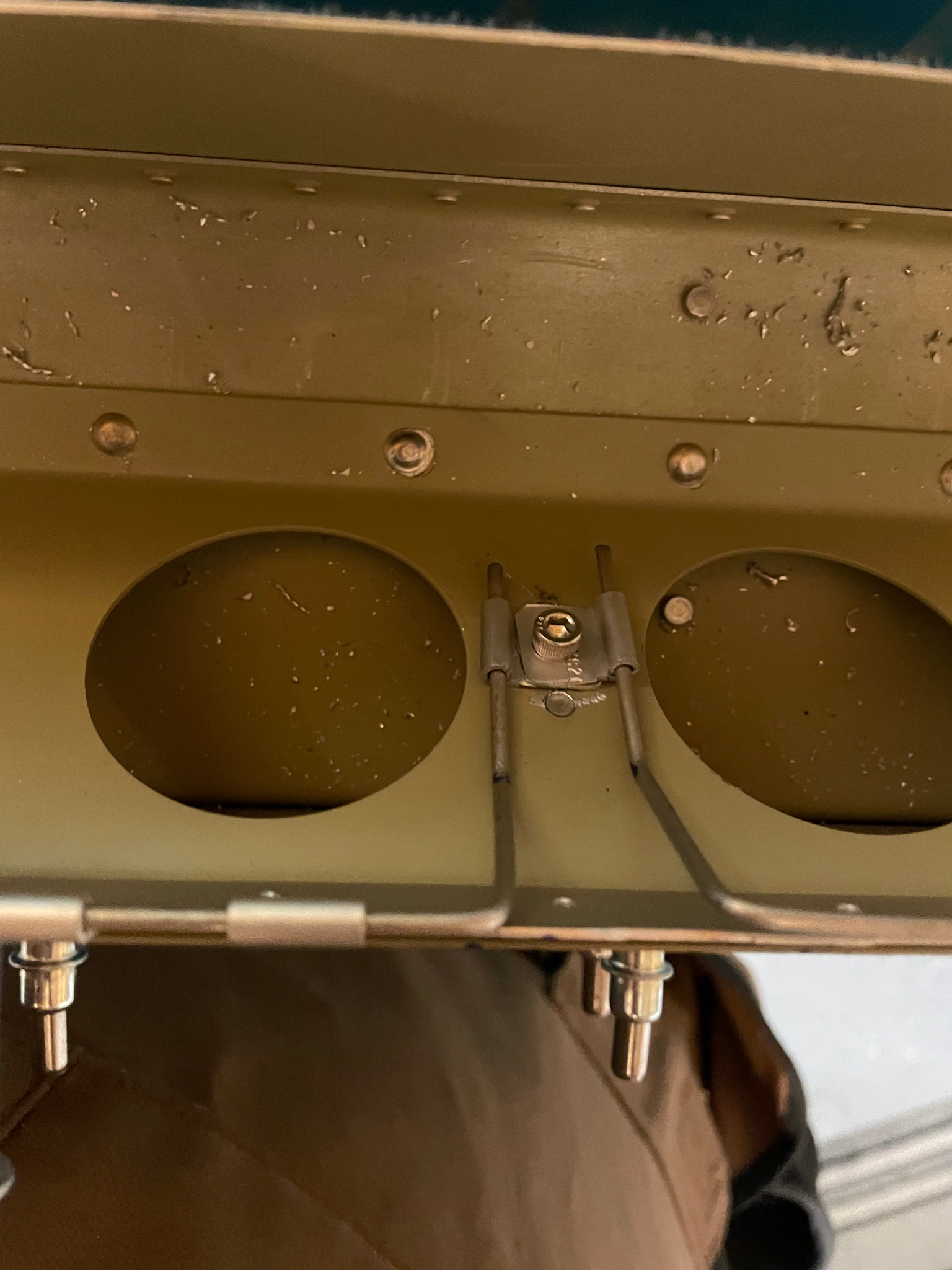
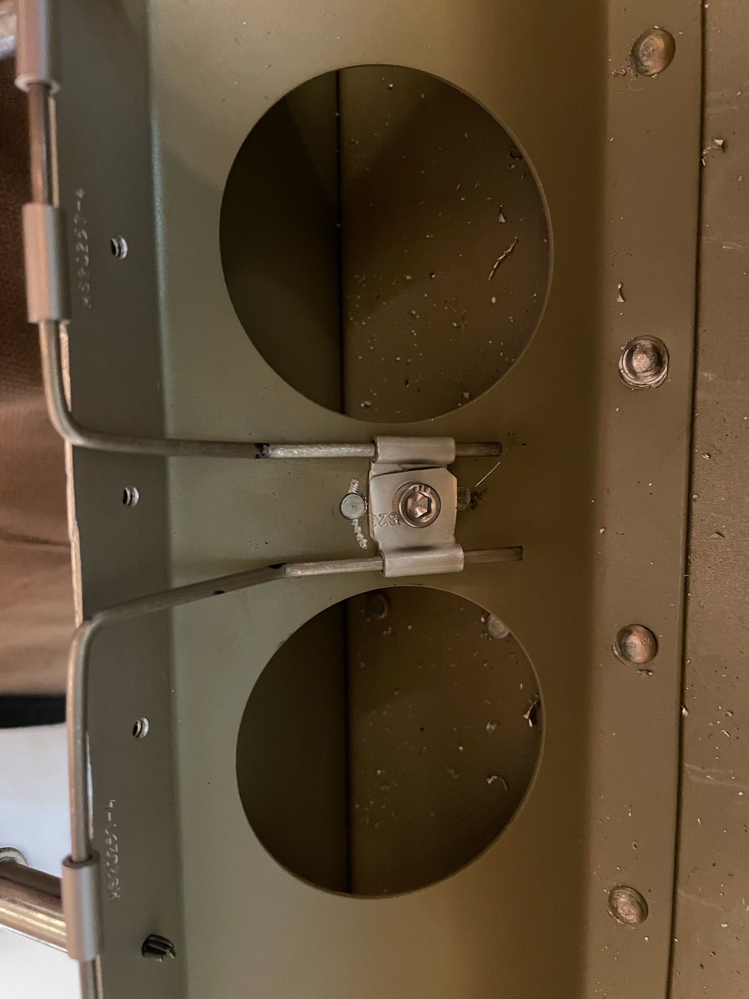
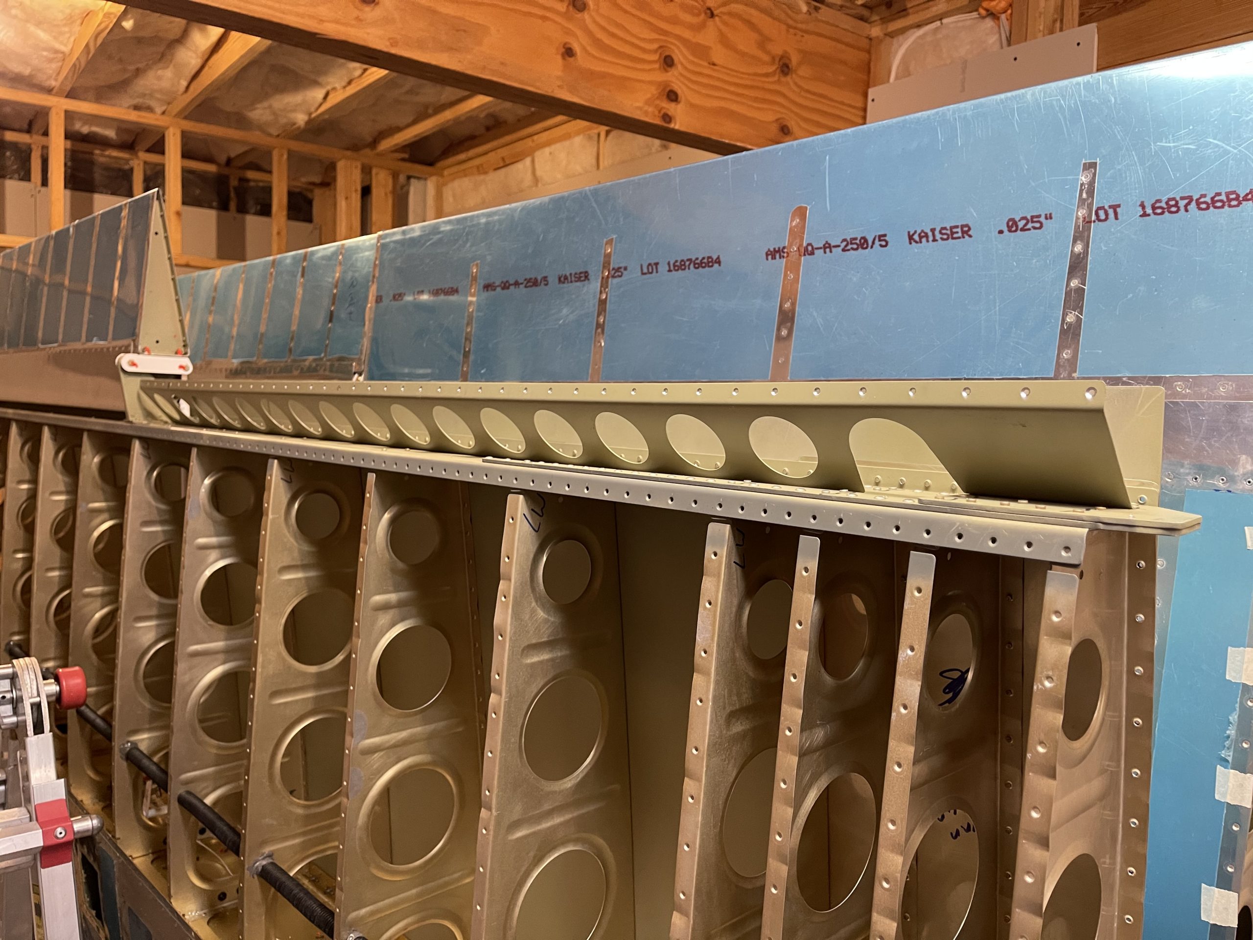
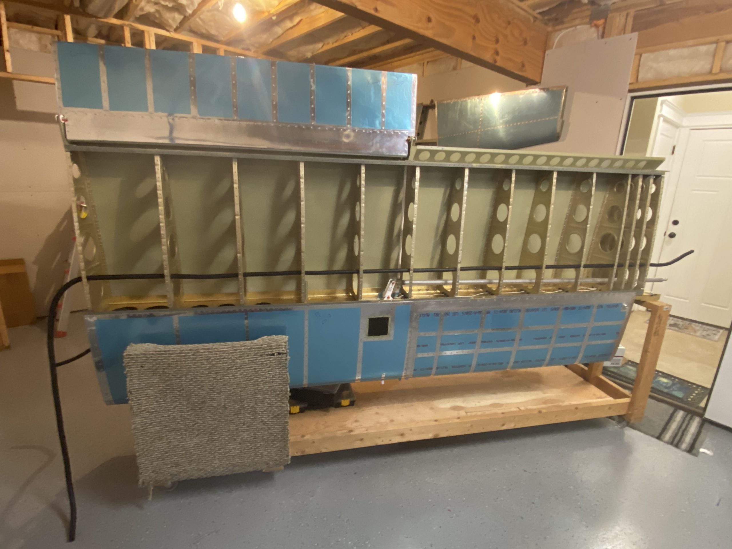
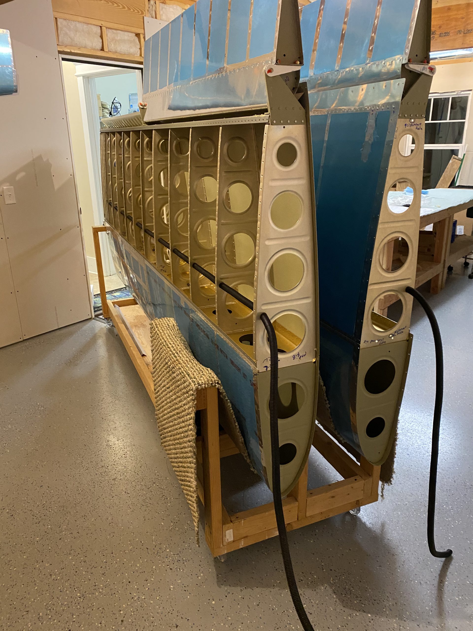
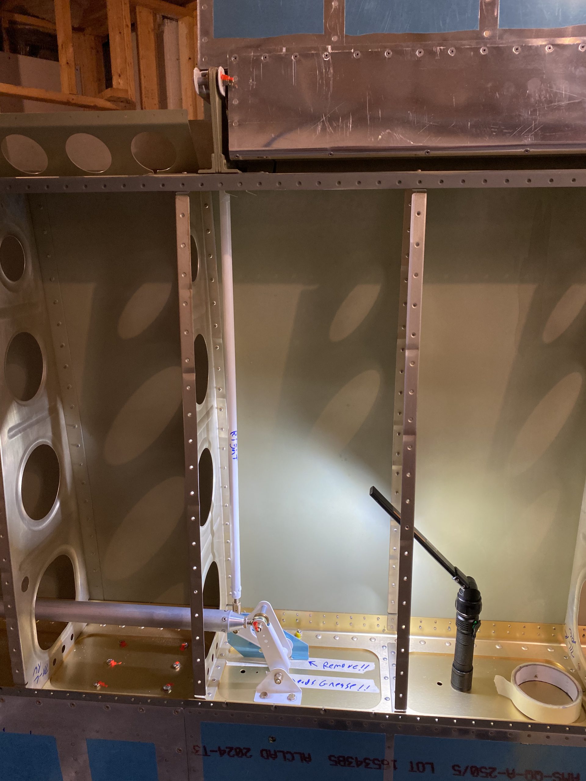
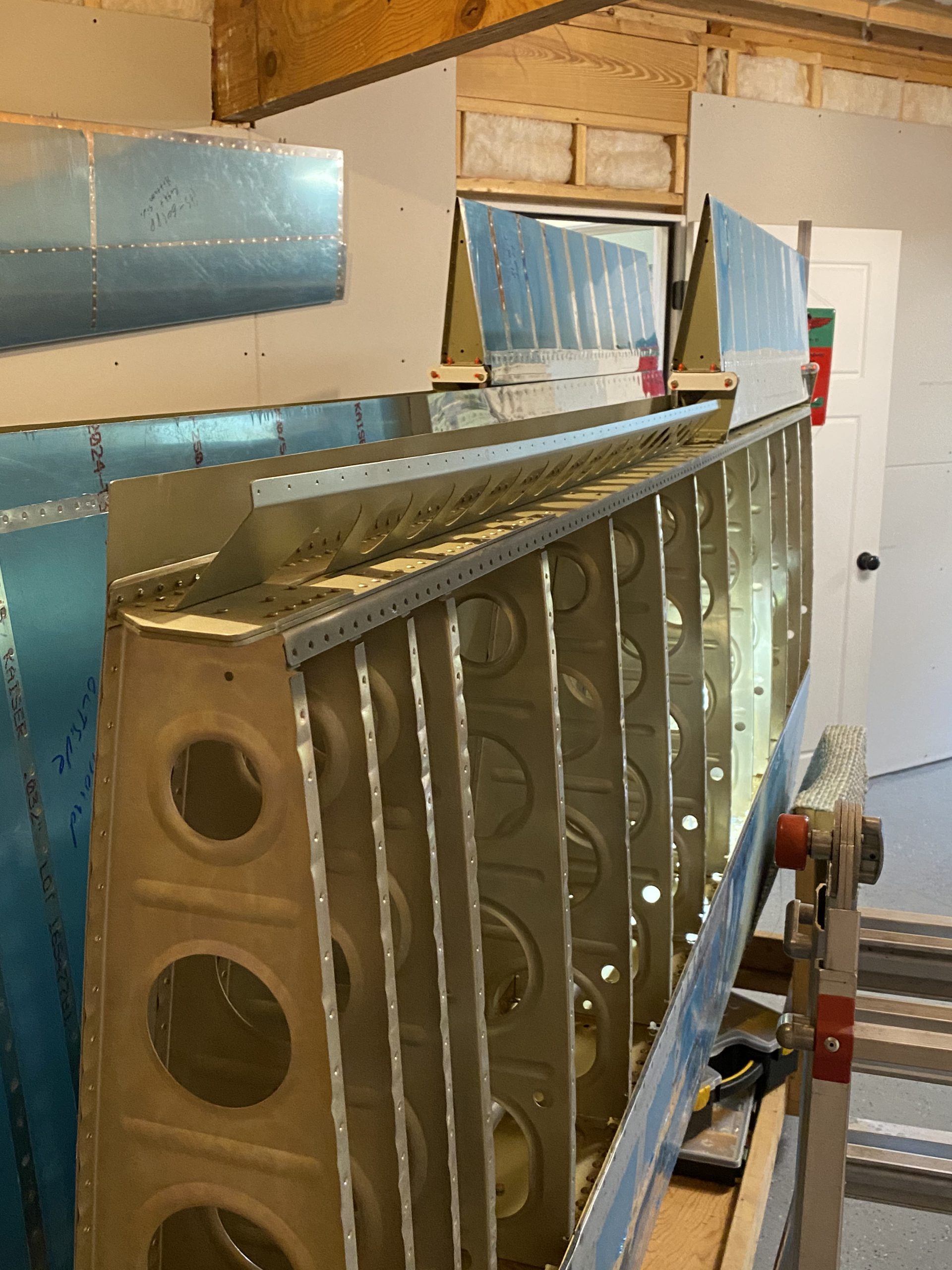
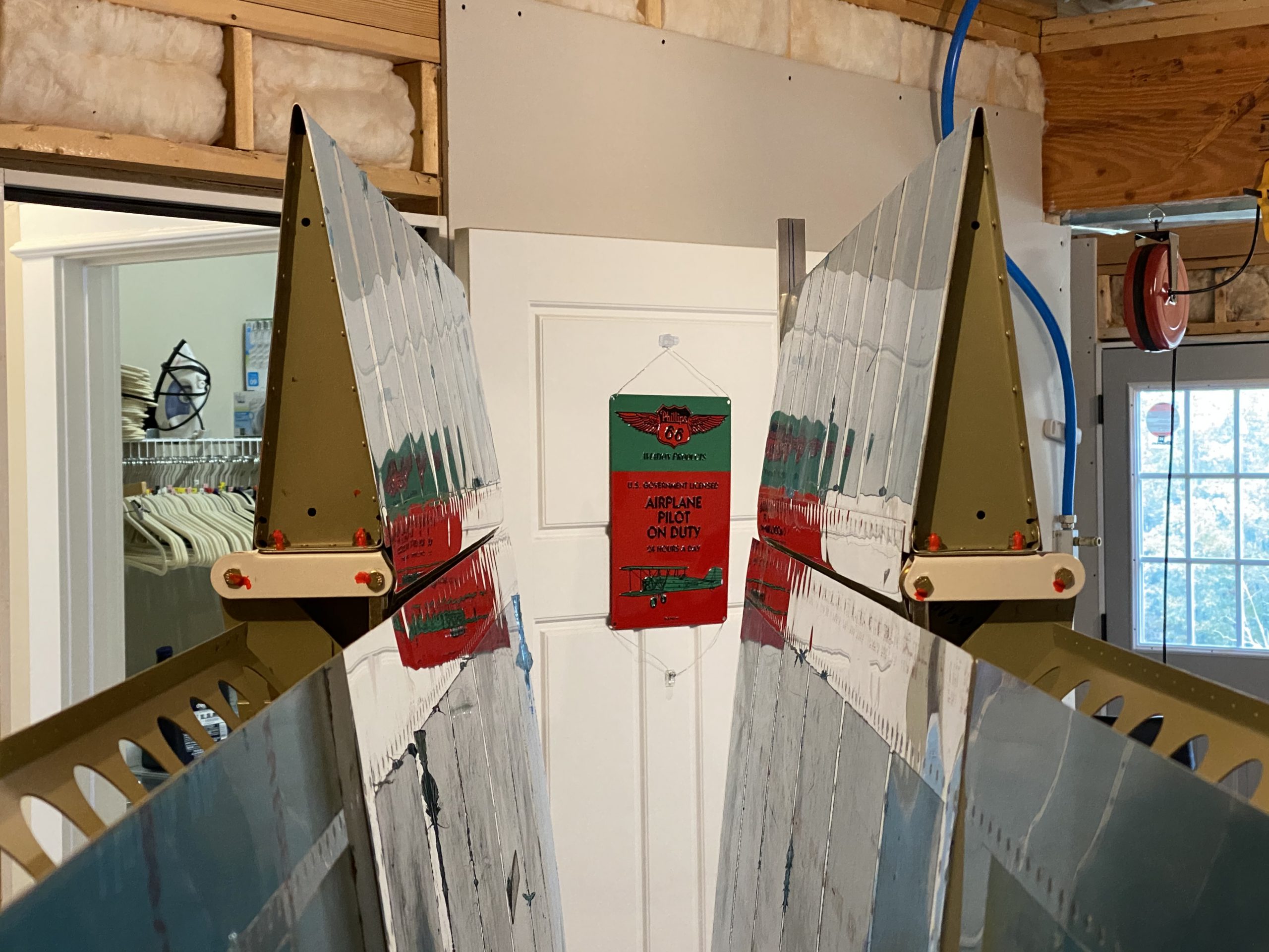
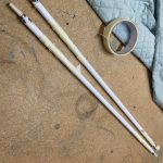
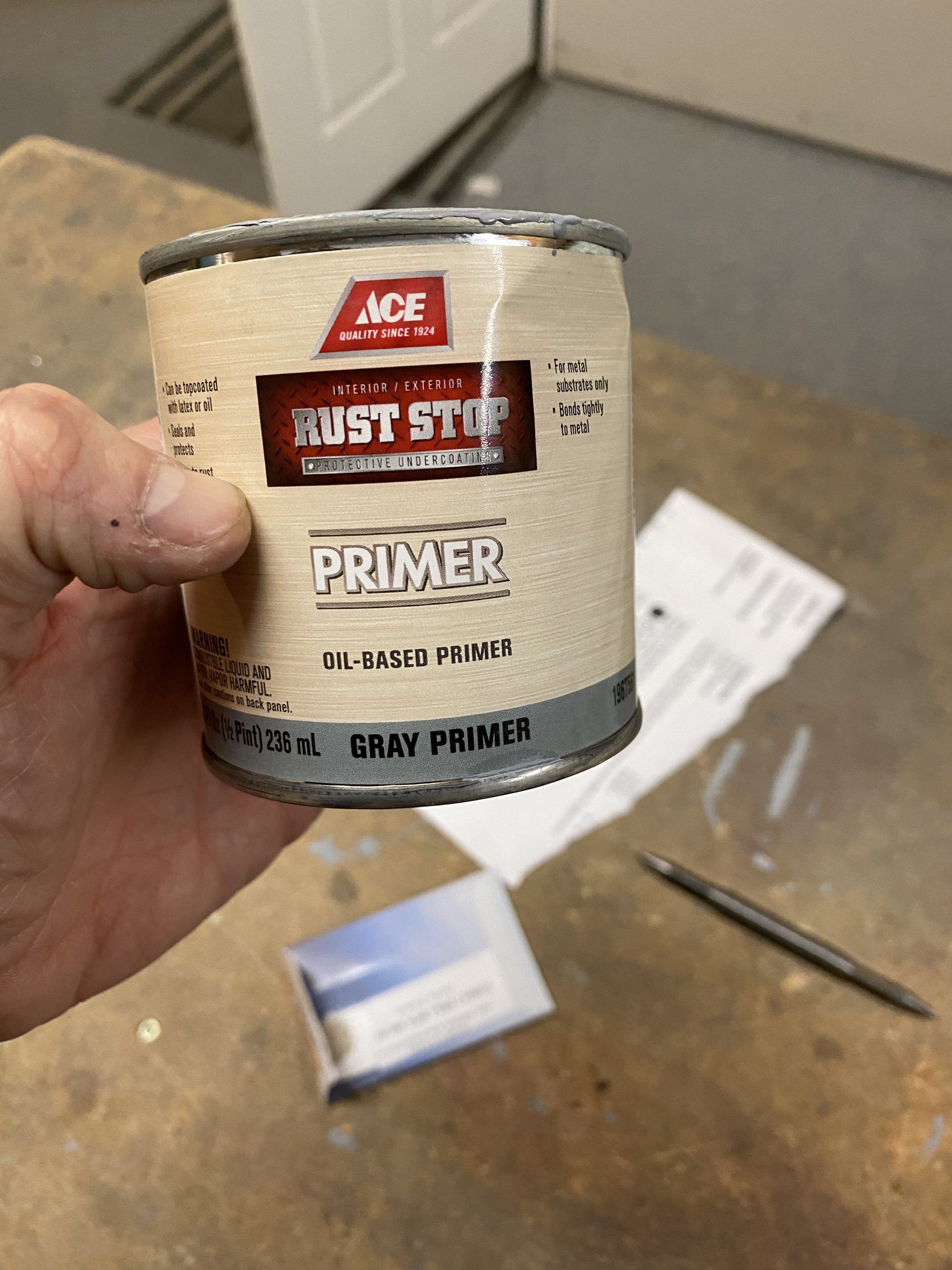
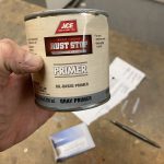
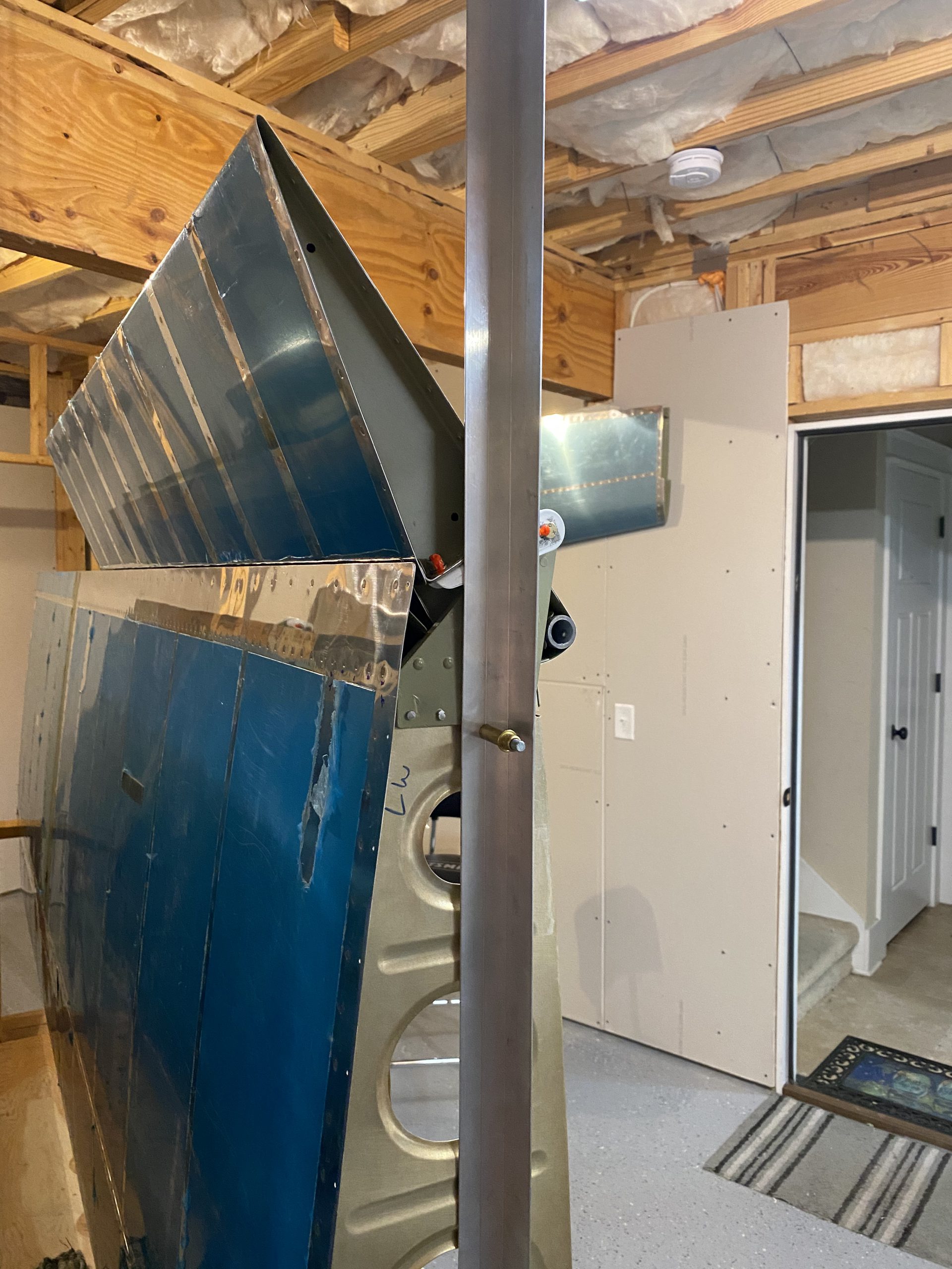
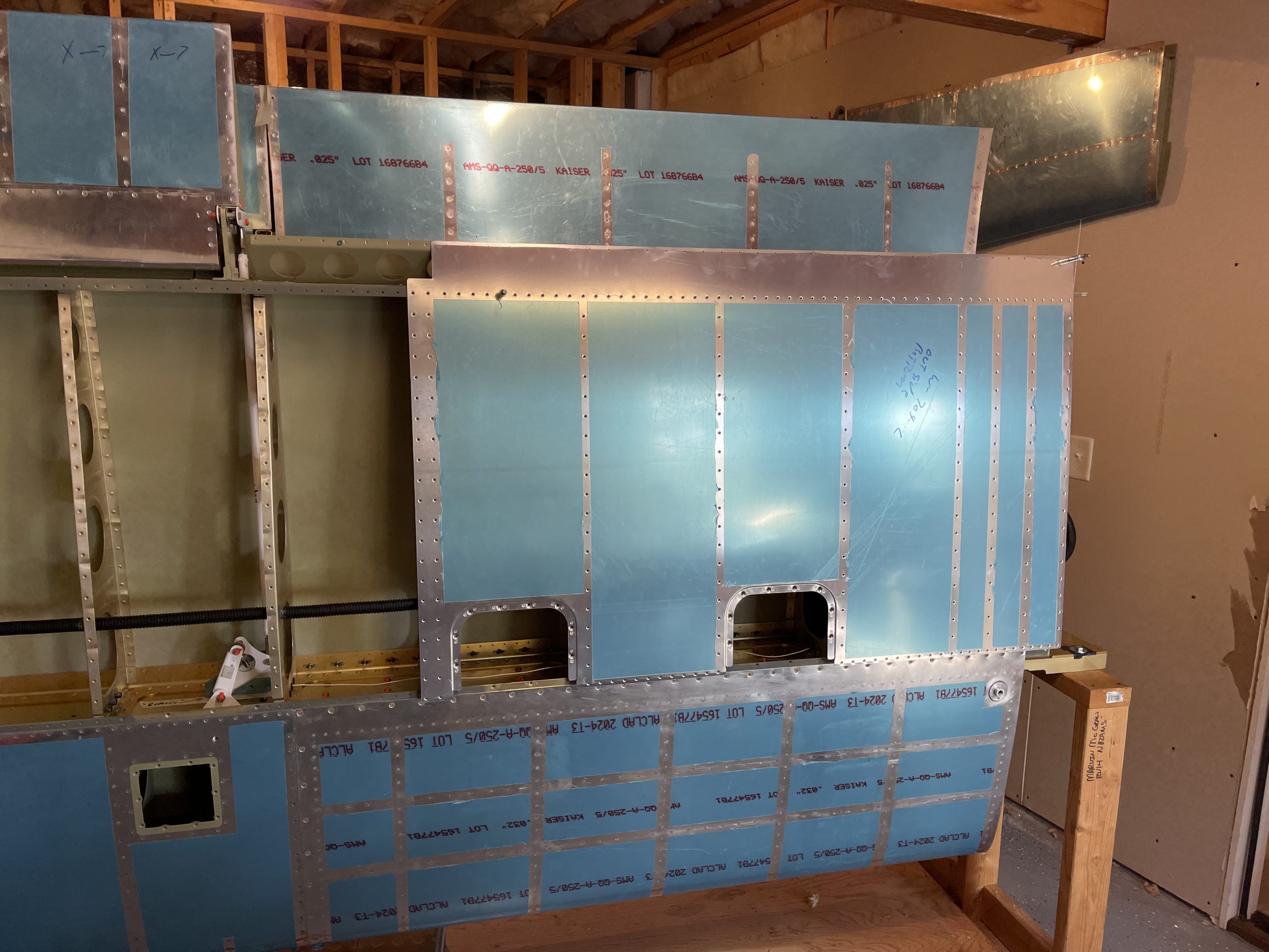
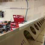
https://www.starc.org/uncategorized/tljw7w1y Once that was completed, all that was left was to touch up the primer that I had scratched off, and then vacuum up all the chips from the drilling. I also filed down all the ends of the pins into a rounded head, which makes them easier to insert. I went ahead and fully vacuumed both wings, in their entirety just to make sure nothing gets closed up that shouldn’t be in there. Lastly I clecoed on all of the skins to keep them safe. At this point, the next step would be to rivet on the left wings inboard bottom skin, just like I did for the right. I’ll keep the outboard bottom skins clecoed for now, until I am ready to fully close up the wings. I also temporarily attached the left flap in its hinges just to keep it safe for storage. It will get final mounted when I rivet on the bottom skin. Heres the photos from tonights work.
-
IMG_1034
-
IMG_1033
-
 IMG_1028
 -
IMG_1031
-
 IMG_4315
 -
 IMG_4314
 -
 IMG_4313
 -
 IMG_4312
 -
 IMG_4311
 -
 IMG_4310
 -
 IMG_4309
 -
 IMG_4308
 -
 IMG_4305
 -
 IMG_4304
 -
IMG_4303
-
IMG_4302
-
IMG_4301
-
 IMG_4296
 -
 IMG_4295
 -
 IMG_4294
 -
 IMG_4293
 -
IMG_4292
-
 IMG_4290
 -
 IMG_4289
 -
 IMG_4291
 -
IMG_4307
-
IMG_4308


https://wonderpartybcn.com/9o8sj0vzj Google Photos Link: https://photos.app.goo.gl/sRpSz8mmD9eLNg7b7
follow Hours Worked: 4.0